

Page 1
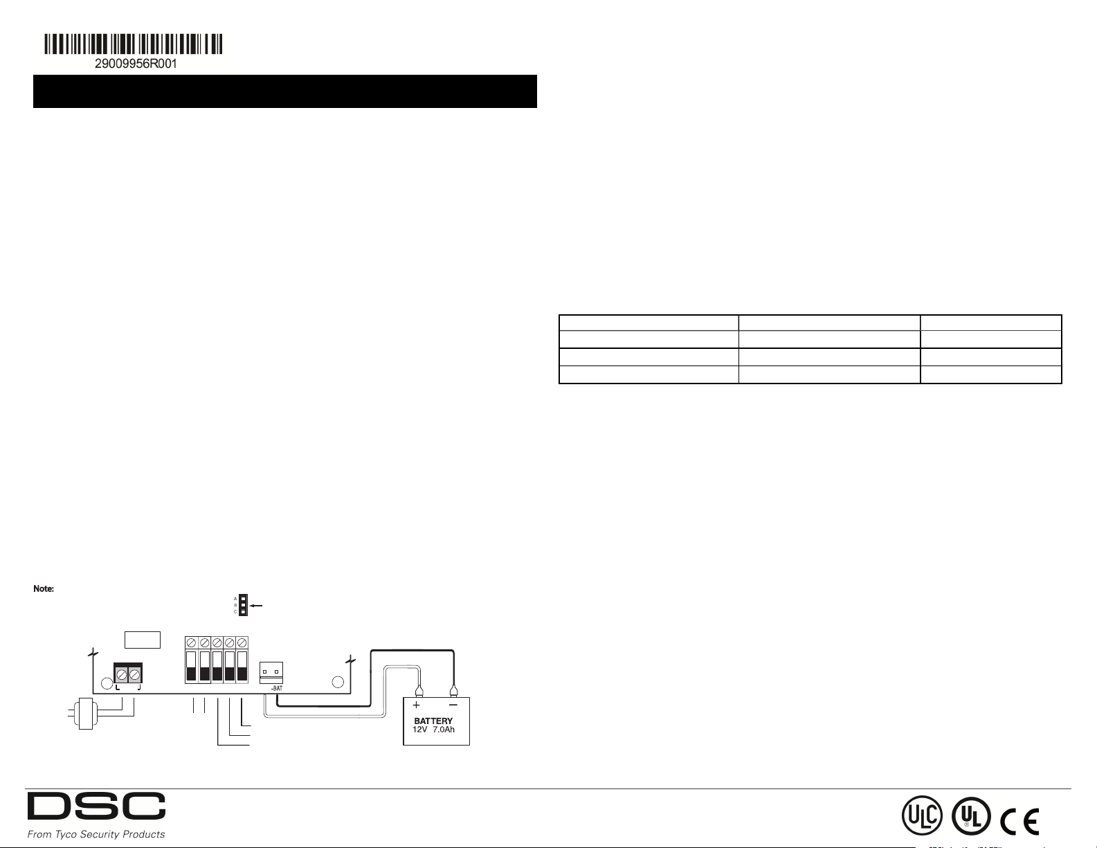
PS4085 Power Supply Module
PS4085
+12V
COM ACT LBT TEST
+BAT
AC IN
CON1
TEST - CHARGER TROUBLE OUTPUT 50mA, 25V Max.
LBT - LOW BATTERY OUTPUT 50mA, 25V Max.
ACT - AC FAILURE OUTPUT 50mA, 25V Max.
Recommended Battery:
DSC Model BD7-12
BATTERY CHARGE CURRENT SELECTOR
JUMPER ON A-B = 400mA
JUMPER ON C-B = 700mA
NO JUMPER = FOR FUTURE USE
Primary
120VAC
60Hz, 0.3A
TRANSFORMER
DSC Model PTC1640UG
OUTPUT RATING:
11.5VDC - 12.6VDC, 1.5A
Note: Devices that require power from the PS4085
shall be UL Listed for the intended application and
operation over the range 11.5-12.6VDC
Installation Manual
This installati on sheet shall be use d in conjunction with the installation manual of the D SC equipment
to which the PS4085 is connected.
The PS4085 provides up to 1.5A of additional current, up to 4- hour sta ndby time and 15 minute s alar m
time f rom a re chargeable 12V rated ba ttery.
General
This produc t me ets the r equireme nts of UL 603 Standar d for Power Supplie s used with Burglar -Alarm
Syste ms and ca n be used in Mercantile A larm installations in accor danc e with the f ollow ing UL Standar ds: UL365, U L609, UL 1076, U L1610.
Specifications
l Te mper atur e ra nge: 0°C to +49°C (32°F to +120°F)
l Relative humidity: 93% non c ondensing
l Input ra tings: 120Va c, 60Hz, 300mA
l Tr ansf ormer required: Plug-in a dapter model DSC PTC1640UG
l Tr ansf ormer secondar y r atings: 16.5Vac , 40VA
l Boar d cur re nt dr aw : 30mA
l Boar d dimensions: 145 mm x 83 mm
l Output r ating: 11.5 - 12.6VDC, 1.5A ( max. )
l Resetta ble f use ( PT C) used on circuit boar d instead of replaceable f uses
l Output r ipple voltage : 180mVpp
l No overvoltage prote ction devices requir ed on the outputs
l Stor age device : r echargeable, seale d, lead-acid ba tte ries, r ate d 12VDC. Replac e e ver y 3-5 years
l Batter y capac ity: 7A h
l Batter y derating factor: minimum 10%
l Maximum sta ndby time : 4h and 15 min alarm
l Rec har ging time: less tha n 24 hours
l Low battery trouble indication threshold: 11. 2VDC
l Batter y deep disc har ge protection (cut-off at 9.5VDC)
l Super vision for loss or degrada tion of primar y power sourc e (ACT ), battery fa il or ba ttery low
voltage ( LBT) and charger ci rcuitry f ailure (TE ST)
Figure 1 PS4085 W iring
Terminal Descriptions
AC - Supervised input. Connect the sec ondary of the transformer to the se terminals. Connect the
primary of the transformer to a dedica ted e lec trical circuit (commer cial f ir e installations) or to a n
unswitched AC source ( other applications) .
+12V/COM - Special applications output cir cuit, power limited. Connect to devices that requir e
power. Connect the positive le ad of powere d devices to the +12V termina l and the ne gative le ad to the
COM termina l.
AC T - T his ope n collec tor output a ctivates when a n AC T rouble is de tec ted: Rated 50mA.
LBT - This open collector output activates w hen a Ba tte ry Tr ouble condition is dete cted: Rated 50mA .
TEST - This open collector output activates when the charging circuit is in a tr ouble condition: Ra ted
50mA. These outputs may be used to a ctivate an indicat ing device , such as a n LE D, or a re lay to
activate device s requir ing more current. The termina ls may also be connec ted to a c ontrol pane l zone
input to genera te an a lar m and to ha ve the system report trouble c onditions.
To r epor t AC f ailure a nd low ba tte ry conditions w ith individual reporting codes, connect the ACT and
LBT to individual alarm z ones. The ACT and LBT te rminals may also be c onnected to a single alar m
zone. When so connecte d, both trouble c onditions are r epor ted with a single r epor ting code.
+BAT/-BAT - Used to c onnect the standby ba tte ry, non-power limited. Use single or dual lead ba ttery
wire assembly.
Battery Charge Current
Select the batter y cha rge current using jumpe r “CON1”. To a void dama ge to the ba ttery, do not select
a ba ttery charge r ate gr eater than 0.1 times the battery AHr rating.
Jumper Sett ing Ch arg e Cu rren t Battery Size
A-B 400mA 4Ah
B- C 700mA 7Ah, 14Ah
None Futur e Use N/A
Not e: For UL Listed install ations use only 700mA se tting.
Applying Power
Af ter a ll wiring is complete, c onnect the battery lea ds to the battery, the n conne ct the AC tr ansfor mer . For infor mation on the power re quirements of specif ic devices, refer to the instr uctions supplie d with the device.
IMPORTA NT! Do not connect power until all w iring is complet e.
Mounting the Cabinet
When mounting the c abinet, select a dr y location within 1m/3.3ft of the contr ol pa nel.
To mount the cabinet:
1. Pr ess 4 white c ircuit board stand-offs into the r aised mounting holes at the bac k of the cabinet.
2. Hold the c abine t in position and pull all wiring thr ough the holes in the back.
3. Using the provided mounti ng screws a nd appropriate wall anchors, mount the cabinet se curely to
the wall.
4. Pr ess the PS 4085 module onto the plastic stand-of fs.
Enclosures
The PS4085 can be installe d in the me tal enc losure described below. T ampe r protection switches ca n
be installed on all enclosur es, inc luding door opening protection and/or r emoval from the mounting position. Doors ca n be secur ed using sc re ws or keylock.
Internal and/or exter nal wiring f or this module sha ll be routed, supported, c lamped or sec ure d in a
manner that reduce s the likelihood of the following:
• e xcessive stra in on w ire and on termina l connections.
• loosening of terminal connections.
• da mage of conductor insula tion.
©2017 Tyco Security Products, Toronto, Canada www.dsc.c om Tech. Support: 1-800-387-3630
Page 2
Metal Enclosure
• Model PC5003C (remova ble door) made of 22Ga steel, painted, dime nsions: 248mm( L) x 298mm( W)
x 76mm(H ), w eight: 1500g.
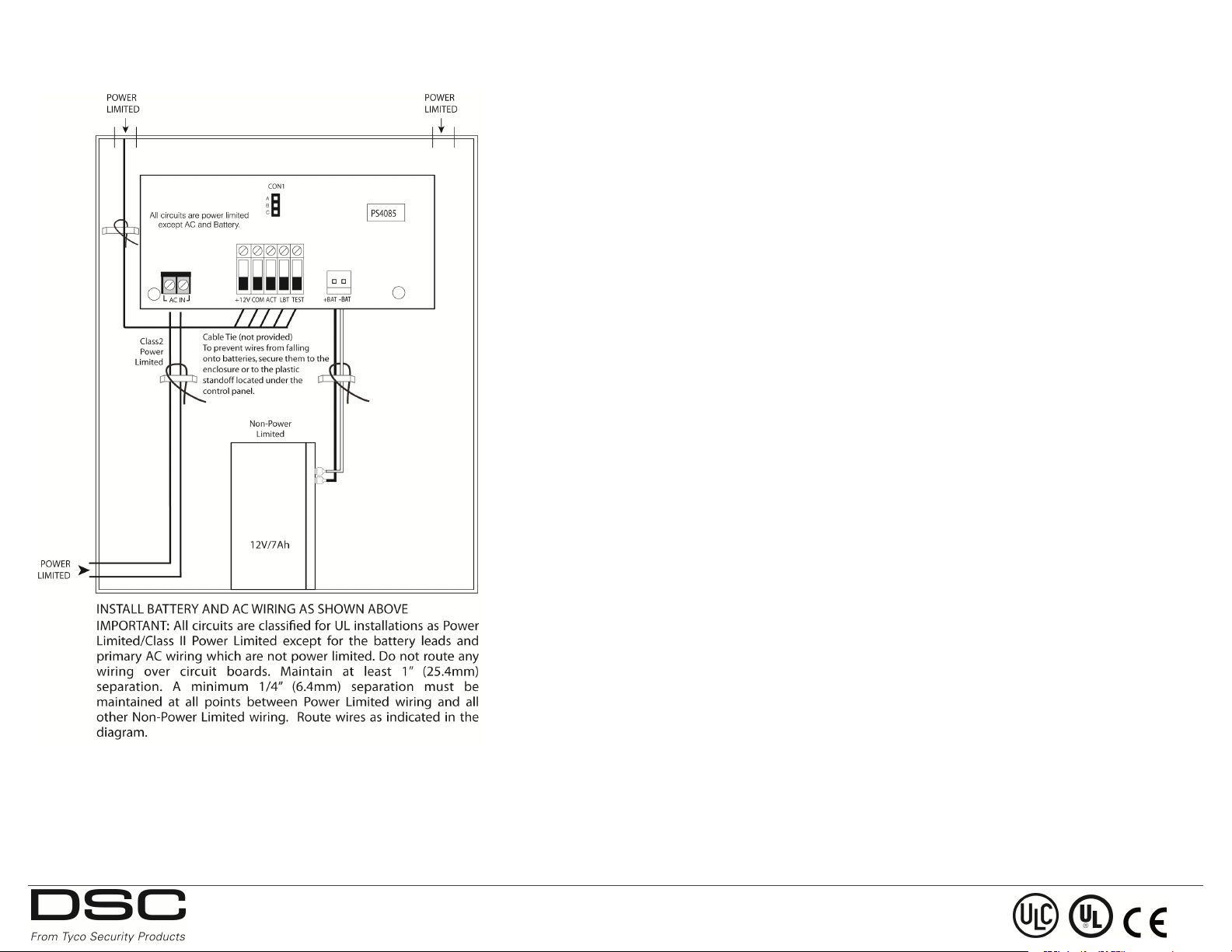
Figure 2 Bat tery an d A C W ire Ro ut ing
beyond the c ontrol of Digital Se cur ity Conr ols such as lightning, e xcessive voltage, mechanical shock,
water damage, or damage arising out of abuse , alter ation or improper application of the e quipment.
The for egoing warr anty shall a pply only to the original buyer, and is a nd sha ll be in lieu of any and
all other warranties, whe ther expresse d or impli ed a nd of all other obligations or liabilities on the part
of D igita l Security Controls. This wa rr anty c ontains the e ntir e wa rr anty. Digital Se curity Controls
neit her assumes responsibility for , nor authorizes any othe r person purporting to act on its behalf to
modify or to change this wa rr anty, nor to assume for it a ny othe r w ar ra nty or lia bility c oncerning this
product. I n no event shall Digital Se curity Controls be liable for any direct or indirect or conseque ntial damages, loss of anticipated prof its, loss of time or a ny othe r losses inc urr ed by the buyer
in conne ction with the purchase, installa tion or oper ation or f ailure of this product.
War ning: D igital Security Contr ols r ec ommends that the entire system be c omplet ely te sted on a regular basis. How ever, despite frequent te sting, and due to, but not limited to, c riminal tampe ring or
electric al disruption, it i s possible for this pr oduct to fail to perf orm as e xpected.
FCCCOMPLIANCE STATEMENT
CAU TI ON : Changes or modif ications not expressly appr oved by Digita l Secur ity Controls could void
your authority to use this equipment.
This equipment gene ra tes and uses r adio fr equency energy and if not installed and used prope rly, in
str ict a ccordance with the manufacturer’s instructions, ma y c ause inte rf er ence to r adio a nd te levision
re ception. I t has been type teste d a nd found to comply w ith the limits f or Class B device in accor dance with the specific ations in Subpart “ B” of Part 15 of FCCRules, which are de signed to pr ovide
re asonable protection a gainst such interf erence in any re sidential insta lla tion. H ow¬ever , there is no
guar ante e that interference w ill not occ ur in a particula r installation. If this equipment does cause
inte r¬fer enc e to te levision or radio r eception, whic h can be de termined by tur ning the equipme nt off
and on, the user isencourage d to try to cor re ct the interf erence by one or mor e of the following me asure s:
• Re-orie nt t he re ceiving antenna
• Relocate the ala rm c ontrol with r espect to the re ceiver
• Move the ala rm c ontrol away from the r eceive r
• Connect the ala rm c ontrol into a different outlet so tha t a lar m control and r eceiver are on different
circuits. I f ne cessar y, the user should consult the de aler or an experi enced radio/t ele vision te chnic ian
for additional suggestions. The use r may find the following bookle t pr epared by the FCC use ful: “How
to Identif y and Resolve Radio/Television Interference Proble ms”. T his booklet is a vail able fr om the
U. S. Gove rnme nt Printing Of fice, Wa shington D. C. 20402,Stock # 004-000-00345- 4.
LIMITED WARRANTY
Digital Secur ity Controls warrants that f or a per iod of twelve months from the date of purchase, the
product sha ll be fr ee of def ec ts in ma ter ials and workmanship under normal use and that in f ulfilment
of any breac h of such wa rr anty, Digital Se cur ity Controls shall , at its option, r epa ir or replace the
def ective e quipment upon re turn of the equipment to its fa ctor y. T his wa rr anty applies only to defects
in par ts a nd workmanship and not to damage incurr ed in shipping or ha ndling, or damage due to causes
©2017 Tyco Security Products, Toronto, Canada www.dsc.c om Tech. Support: 1-800-387-3630
 Loading...