

DSC PTK5507, PowerSeries PTK5507 Installation Instructions Manual

Installation Instructions/Instructions d’installation/Instrucciones de instalación/Instruções de instalação
WARNING: Please refer to the System Installation Manual for information on limitations regarding product use and function and information on the limitations as to liability of the manufacturer.
NOTE: These instructions shall be used in conjunction with the system Installation Manual of the Control Panel with which this equipment is intended to be used.
ATTENTION: Ce manuel contient des informations sur les restrictions concernant le fonctionnement et l’utilisation du produit et des informations sur les restrictions en ce qui concerne la
responsabilité du fabricant. La totalité du manuel doit être lu attentivement.
NOTE: Ce manuel doit être utlisé en conjunction avec le Manuel d’installation du Panneau de contrôle.
ATENCIÓN: Consulte el Manual de instalación del sistema para obtener información sobre las limitaciones del uso y funciones del producto, asi como las limitaciones de la reponsabilidad del fabricante.
NOTA: Estas instrucciones deberán utilizarse conjuntamente con el Manual de instalación del sistema del Panel de control con el que se vaya a utilizar este equipo.
AVISO: Consulte o Manual de instalação do sistema para obter informações acerca das limitações relativas à utilização do produto e funções e informações acerca das limitações relativas à imputação
de responsabilidades ao fabricante.
NOTA: Estas instruções devem ser utilizadas em conjunto com o Manual de instalação do sistema do painel de controlo com o qual este equipamento se destina a ser utilizado.
PTK5507 v1.1
English
S
D
c
a
r
d
gently
push
in
press
to
eject
mounting hole
mounting hole
mounting hole
wiring slot
mounting hole
hole for
tamper
screw
PTK5507
GRN
YEL
BLK
RED
NOT USED
Installation Instructions
The PTK5507 keypad can be used on security systems with up to 64
zones. These keypads are compatible with the latest version of the
Power Series V4.2+security systems.
Specifications
• Temperature range: 0°C to +49°C (32°F to 120°F)
• Humidity (MAX ): 93%R.H. non-condensing
• Plastic enclosure protection degree: IP30, IK04 (touchscreen
excluded)
• Voltage rating: 12V DC nominal
• Connects to contro l panel via 4-wire Keybus
• Keybus distance: 60 m (200 ft.) (max.); keybus distance in extra
power mode: 33.5 m (110 ft)
• Up to 8 keypads per system
• PTK5507 current draw: 100 mA standby (screen off)/200 mA
activated or alarm (regular power mode)/300 mA activated or
alarm (Extra Power Mode)
• Wall moun t tamper
• 5 progra mmable function keys
• Ready (Green LED), Armed (Red LED), Trouble (Yellow LED), AC
(Green LED)
• Touchscreen display: 8.5" x 5.1" x 0.8" [127.9 mm (L) x 195
mm (W) x 20.35 mm (D)]
• SD card slot: holds any standard Secure Digital (SD) card* (32 x
24 x 2.1 mm) containing photos
*If necessary, the SD card can be formatted to file system FAT16
or 32 using a PC. The maximum size SD card supported is 32GB.
• Wiring: stand ard four-wire connection
• Viewing angle: horizontal viewing angle: 70° (typ.)
• Vertical viewing angle: 70° (top), 50° (bottom) (typ.)
• Brightness: 280 cd/m
Unpacking
The Power keypad package includes the following parts:
• One Power keypad
• Five mounting screws
• Five anchors fo r wall-mounting screws
2
• 1 tamper switch (required for UL commercial burglary listed
installations)
• Install ation Instructions
• User Ma nual
Mounting
You should mount the keypad where it is accessible to designated
points of entry and exit. Once you have selected a dry and secure
location, perform the following steps to mount the keypad.
Mount and Wire Keypad
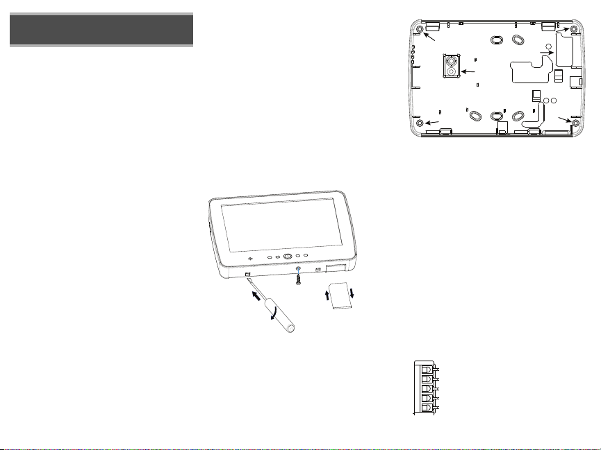
1. Remove the SD card before opening the touchscreen (see
Figure 1).
WARNING: Disassembling the touchscreen
without removing the SD card will damage
the unit.
2. Remove screw at the bottom of the keypad.
3. Insert screwdriver into slots and pry up to remove cover.
Figure 1 - Removing the backplate
4. Secure keypad backplate to wall using mounting holes.
(See Figure 2.) Use all 4 screws provided unless mounting
on a single gang box. Use the plastic anchors supplied if the
unit is to be mounted on drywall. If using the keypad
tamper, secure the tamper plate to the wall with a screw.
Figure 2 - Mounting the backplate
5. Run wire through wiring slot. Connect keybus wiring to
keypad (see Wiring section).
6. Place keypad into backplate, ensuring the wire is pushed
back into the wall as much as possible. Route the wire
inside the keypad ensuring high components are avoided.
Snap the front assembly closed, ensuring that there is no
pressure to the keypad from the wire below.
NOTE: If any tension is found between the
front keypad assembly and wiring, please
open the keypad, re-route the wire and close
again. Repeat these steps until the keypad is
closed properly.
Wiring
1. Before wiring the unit, ensure that all power (AC
transformer, telecommunication network, and battery) is
disconnected from the control panel.
2. Connect the four Keybus wires from the control panel
(green, yellow, black, and red) to the keypad terminals.
Refer to Figure 3.
Figure 3 - Wiring

Applying Power
Toggle Option
1 _ _ 4 _ _ _ _
Once all wiring is complete, and the equipment is secured to the
building structure with at least two screws, apply power to the control
panel:
1. Connect the battery leads to the battery.
2. Connect the AC transformer.
3. Connect telecommunication network (e.g., telephone line,
Ethernet cable, etc.).
For more information on control panel power specifications, see the
control panel Installation Manual.
CAUTION: Route all the wiring according to
the local codes and regulations.
Programming the Keypad
There are several
programming
options available
for the keypad.
These are
described below. Programming the keypad is similar to
programming the rest of the system. When you are in the keypad
programming sections, the keypad will display which options are
turned on. To turn an option on or off, press the number
corresponding to the option on the number pad. The numbers of the
options that are currently turned ON will be displayed. For example,
if options 1 and 4 are on, the display will look like the diagram
shown.
For information on programming the rest of your security system,
please refer to your system’s Installation Manual.
NOTE: Do not enable keypad blanking (panel
programming, section 016, option 3). If keypad blanking is enabled, the panel will stop
sending out the status and the keypad status will be inaccurate.
Enrolling the Keypad
The keypad will need to be assigned to a partition and slot if
supervision or keypad zones are being used. Keypad assignments
and keypad option programming must be done at each keypad
individually.
The 1st digit of keypad assignment is used to determine partition
assignment (1 to 8). If partitioning is not used, enter [1].
The 2nd digit of keypad assignment is used to determine slot
assignment for keypad supervision. Each keypad will be assigned a
different slot number from 1 to 8.
Enter the following at each keypad installed on the system:
1. Enter Installer Programming by pressing Options, Installer
Menu [Installer Code], then Keypad Mode Prog.
2. Press [000] for keypad programming.
3. Press [0] for Partition and Slot Assignment.
4. Enter the 1st digit (1 to 8 for partition assignment).
5. Enter the 2nd digit (1 to 8 for slot assignment supervision).
6. Press the [#] key twice to exit programming.
7. After assigning all keypads, perform a supervisory reset by
entering Options, Installer Menu, [Installer’s Code], [902],
and waiting for 60 seconds.
8. Press the [#] key to exit programming after 60 seconds.
Programming Labels
1. Enter Options, Installer Menu [Installer Code], then Label
Progra mming.
2. Select the desired Label to Program.
3. Using the keyboard on the screen, enter the new label and
press save when complete.
Broadcasting LCD Labels
All LCD programming is done per keypad. If more than one LCD
keypad is present on the system, labels programmed at one keypad
can be broadcast to all other LCD keypads. Perform the following
procedure in order to broadcast labels:
Step 1 - Program one LCD keypad completely.
Step 2 - Make sure all LCD keypads are connected to the Keybus.
Step 3 - Enter keypad programming by pressing Options, Installer
Menu [Installer Code], Keypad Mode Prog, then enter section [
,
] at the keypad that was programmed. The keypad will
[998] [
now broadcast all the information programmed to all the other LCD
keypads on the system.
Step 4 - When the keypad is finished press the [#] key to exit.
,
ASCII Characters
Changing Backlight (Brightness Level)
1. Press Options, Keypad Config, then Backlight.
2. Use slide bar to adjust brightness to desired setting.
3. Press the Back or Home button.
Changing the Buzzer Level
1. Press Options, Keypad Config, then Buzzer Control.
2. Use slide bar to adjust buzzer to desired setting.
3. Press the Back or Home button.
Entering Calibration Mode
1. Press Options, Keypad Config, then Calibration.
2. Press the cross hairs on the screen to complete calibration.
NOTE: Calibration mode can also be entered
by pressing and holding the home button for
5 seconds.
Changing the Background Image
1. Press Options, Installer Menu [Installer Code], Keypad
Programming, then Background Image.
2. Select image to use image from SD card as background
image.
3. To exit, press Back or Home button.
]

Dark Text Enable/Disable
1. Press Options, Installer Menu [Installer Code], Keypad Programming, then Options.
2. Select the desired text color by enabling or disabling Dark Text. (Disabling makes the text
white.)
NOTE: This feature affects only the text on the Classic (Square)
Button Home Page.
Changing Home Page Look:
1. Press Options, Keypad Config, Home Page.
2. Select the desired view from either classic look (square) or contemporary (rondel).
3. To exit, press the Back or Home button.
Performing a Firmware Upgrade:
1. Insert an SD card in the PTK5507 with the new firmware.
2. Press Options, Installer Menu [Installer Code], Keypad Programming, then Firmware Upgrade.
3. Select OK to perform a firmware update (if a new firmware version is available).
Enabling/Disabling Fire, Auxiliary and Panic Buttons
1. Press Options, Installer Menu [Installer Code], Keypad Programming, then Options.
2. Enable/disable the desired Fire, Auxiliary and Panic buttons.
NOTE: The Fire, Auxiliary and Panic buttons are enabled by default on
the PTK5507.
Extra Power Option
The Extra Power option will increase the brightness of the display. To enable the option:
1. Press Options, Installer Menu [Installer Code], Keypad Programming, then Options.
2. Enable or disable the extra power option.
NOTE: Enabling the Extra Power option will put the keypad into a
higher current mode and the keypad will draw 300 mA. In Extra
Power mode, reduce the maximum wire length from 60 m (200 ft.) to
33.5 m (110 ft.)
Changing Function Keys on the Home Page:
1. Press Options, Installer Menu [Installer Code], Keypad Programming, then Home Functions.
2. Assign the desired function to the corresponding key.
3. To exit press the Back or Home button.
Adjusting Screen Time out
1. Press Options, Keypad Config, then Backlight.
2. Select appropriate time for screen time out by using the slide bar.
3. To exit, press Back or Home button.
Accessing Clean Mode
Press Options, Keypad Config, Clean Mode.
NOTE: Clean mode will time out in 30 seconds.
Keypad Enrollment
Enter keypad programming by pressing Options, Installer Menu [Installer’s Code], Keypad
Mode Prog, then [000].
[0] Partition / Slot Assignment
Digit Option Valid Range Default
1st Partition Assignment 1 to 8 1 I_____I
2nd Slot Assignment 1 to 8 8 I_____I
Keypad Programming
Enter keypad programming by pressing Options, Installer Menu [Installer’s Code], Keypad
Mode Prog, then [,].
[001]-[064] Zone Label 1 to 64
ex. For Zone 1 enter section [001], for Zone 2 enter section [002] etc. Default: “Zone 1”-“Zone 64”
Section Zone
[001] 1
[002] 2
[003] 3
[004] 4
[005] 5
[006] 6
[007] 7
[008] 8
[009] 9
[010] 10
[011] 11
[012] 12
[013] 13
[014] 14
[015] 15
[016] 16
[017] 17
[018] 18
[019] 19
I_____I_____I_____I_____I_____I_____I_____I_____I_____I_____I_____I_____I_____I__ _ _I
I_____I_____I_____I_____I_____I_____I_____I_____I_____I_____I_____I_____I_____I__ _ _I
I_____I_____I_____I_____I_____I_____I_____I_____I_____I_____I_____I_____I_____I__ _ _I
I_____I_____I_____I_____I_____I_____I_____I_____I_____I_____I_____I_____I_____I__ _ _I
I_____I_____I_____I_____I_____I_____I_____I_____I_____I_____I_____I_____I_____I__ _ _I
I_____I_____I_____I_____I_____I_____I_____I_____I_____I_____I_____I_____I_____I__ _ _I
I_____I_____I_____I_____I_____I_____I_____I_____I_____I_____I_____I_____I_____I__ _ _I
I_____I_____I_____I_____I_____I_____I_____I_____I_____I_____I_____I_____I_____I__ _ _I
I_____I_____I_____I_____I_____I_____I_____I_____I_____I_____I_____I_____I_____I__ _ _I
I_____I_____I_____I_____I_____I_____I_____I_____I_____I_____I_____I_____I_____I__ _ _I
I_____I_____I_____I_____I_____I_____I_____I_____I_____I_____I_____I_____I_____I__ _ _I
I_____I_____I_____I_____I_____I_____I_____I_____I_____I_____I_____I_____I_____I__ _ _I
I_____I_____I_____I_____I_____I_____I_____I_____I_____I_____I_____I_____I_____I__ _ _I
I_____I_____I_____I_____I_____I_____I_____I_____I_____I_____I_____I_____I_____I__ _ _I
I_____I_____I_____I_____I_____I_____I_____I_____I_____I_____I_____I_____I_____I__ _ _I
I_____I_____I_____I_____I_____I_____I_____I_____I_____I_____I_____I_____I_____I__ _ _I
I_____I_____I_____I_____I_____I_____I_____I_____I_____I_____I_____I_____I_____I__ _ _I
I_____I_____I_____I_____I_____I_____I_____I_____I_____I_____I_____I_____I_____I__ _ _I
I_____I_____I_____I_____I_____I_____I_____I_____I_____I_____I_____I_____I_____I__ _ _I
Label

I_____I_____I_____I_____I_____I_____I_____I_____I_____I_____I_____I_____I_____I__ _ _I
[020] 20
I_____I_____I_____I_____I_____I_____I_____I_____I_____I_____I_____I_____I_____I__ _ _I
[021] 21
I_____I_____I_____I_____I_____I_____I_____I_____I_____I_____I_____I_____I_____I__ _ _I
[022] 22
I_____I_____I_____I_____I_____I_____I_____I_____I_____I_____I_____I_____I_____I__ _ _I
[023] 23
I_____I_____I_____I_____I_____I_____I_____I_____I_____I_____I_____I_____I_____I__ _ _I
[024] 24
I_____I_____I_____I_____I_____I_____I_____I_____I_____I_____I_____I_____I_____I__ _ _I
[025] 25
I_____I_____I_____I_____I_____I_____I_____I_____I_____I_____I_____I_____I_____I__ _ _I
[026] 26
I_____I_____I_____I_____I_____I_____I_____I_____I_____I_____I_____I_____I_____I__ _ _I
[027] 27
I_____I_____I_____I_____I_____I_____I_____I_____I_____I_____I_____I_____I_____I__ _ _I
[028] 28
I_____I_____I_____I_____I_____I_____I_____I_____I_____I_____I_____I_____I_____I__ _ _I
[029] 29
I_____I_____I_____I_____I_____I_____I_____I_____I_____I_____I_____I_____I_____I__ _ _I
[030] 30
I_____I_____I_____I_____I_____I_____I_____I_____I_____I_____I_____I_____I_____I__ _ _I
[031] 31
I_____I_____I_____I_____I_____I_____I_____I_____I_____I_____I_____I_____I_____I__ _ _I
[032] 32
I_____I_____I_____I_____I_____I_____I_____I_____I_____I_____I_____I_____I_____I__ _ _I
[033] 33
I_____I_____I_____I_____I_____I_____I_____I_____I_____I_____I_____I_____I_____I__ _ _I
[034] 34
I_____I_____I_____I_____I_____I_____I_____I_____I_____I_____I_____I_____I_____I__ _ _I
[035] 35
I_____I_____I_____I_____I_____I_____I_____I_____I_____I_____I_____I_____I_____I__ _ _I
[036] 36
I_____I_____I_____I_____I_____I_____I_____I_____I_____I_____I_____I_____I_____I__ _ _I
[037] 37
I_____I_____I_____I_____I_____I_____I_____I_____I_____I_____I_____I_____I_____I__ _ _I
[038] 38
I_____I_____I_____I_____I_____I_____I_____I_____I_____I_____I_____I_____I_____I__ _ _I
[039] 39
I_____I_____I_____I_____I_____I_____I_____I_____I_____I_____I_____I_____I_____I__ _ _I
[040] 40
I_____I_____I_____I_____I_____I_____I_____I_____I_____I_____I_____I_____I_____I__ _ _I
[041] 41
I_____I_____I_____I_____I_____I_____I_____I_____I_____I_____I_____I_____I_____I__ _ _I
[042] 42
I_____I_____I_____I_____I_____I_____I_____I_____I_____I_____I_____I_____I_____I__ _ _I
[043] 43
I_____I_____I_____I_____I_____I_____I_____I_____I_____I_____I_____I_____I_____I__ _ _I
[044] 44
I_____I_____I_____I_____I_____I_____I_____I_____I_____I_____I_____I_____I_____I__ _ _I
[045] 45
I_____I_____I_____I_____I_____I_____I_____I_____I_____I_____I_____I_____I_____I__ _ _I
[046] 46
I_____I_____I_____I_____I_____I_____I_____I_____I_____I_____I_____I_____I_____I__ _ _I
[047] 47
I_____I_____I_____I_____I_____I_____I_____I_____I_____I_____I_____I_____I_____I__ _ _I
[048] 48
I_____I_____I_____I_____I_____I_____I_____I_____I_____I_____I_____I_____I_____I__ _ _I
[049] 49
I_____I_____I_____I_____I_____I_____I_____I_____I_____I_____I_____I_____I_____I__ _ _I
[050] 50
I_____I_____I_____I_____I_____I_____I_____I_____I_____I_____I_____I_____I_____I__ _ _I
[051] 51
I_____I_____I_____I_____I_____I_____I_____I_____I_____I_____I_____I_____I_____I__ _ _I
[052] 52
I_____I_____I_____I_____I_____I_____I_____I_____I_____I_____I_____I_____I_____I__ _ _I
[053] 53
I_____I_____I_____I_____I_____I_____I_____I_____I_____I_____I_____I_____I_____I__ _ _I
[054] 54
I_____I_____I_____I_____I_____I_____I_____I_____I_____I_____I_____I_____I_____I__ _ _I
[055] 55
I_____I_____I_____I_____I_____I_____I_____I_____I_____I_____I_____I_____I_____I__ _ _I
[056] 56
I_____I_____I_____I_____I_____I_____I_____I_____I_____I_____I_____I_____I_____I__ _ _I
[057] 57
I_____I_____I_____I_____I_____I_____I_____I_____I_____I_____I_____I_____I_____I__ _ _I
[058] 58
I_____I_____I_____I_____I_____I_____I_____I_____I_____I_____I_____I_____I_____I__ _ _I
[059] 59
I_____I_____I_____I_____I_____I_____I_____I_____I_____I_____I_____I_____I_____I__ _ _I
[060] 60
I_____I_____I_____I_____I_____I_____I_____I_____I_____I_____I_____I_____I_____I__ _ _I
[061] 61
I_____I_____I_____I_____I_____I_____I_____I_____I_____I_____I_____I_____I_____I__ _ _I
[062] 62
I_____I_____I_____I_____I_____I_____I_____I_____I_____I_____I_____I_____I_____I__ _ _I
[063] 63
I_____I_____I_____I_____I_____I_____I_____I_____I_____I_____I_____I_____I_____I__ _ _I
[064] 64
[077] Second Keypad Options
Default Option ON OFF
ON I____I 1
ON I____I 2
OFF I____I 3
ON I____I 4
OFF I____I 5
ON I____I 6
ON I____I 7
OFF I____I 8
NOTE: Do not attempt to change options 3-8 in Section 077 or the
keypad may not function as desired.
[101]-[108] Partition Labels
ex. For Partition 1 enter section [101], for Partition 2 enter section [102] etc.
Section Partition
[101] 1
[102] 2
[103] 3
Chime Enabled for Zone
Openings
Chime Enabled for Zone
Closings
For Future Use
For Future Use
For Future Use
For Future Use
For Future Use
For Future Use
I_____I_____I_____I_____I_____I_____I_____I_____I_____I_____I_____I_____I_____I__ _ _I
I_____I_____I_____I_____I_____I_____I_____I_____I_____I_____I_____I_____I_____I__ _ _I
I_____I_____I_____I_____I_____I_____I_____I_____I_____I_____I_____I_____I_____I__ _ _I
Chime Disabled for Zone
Openings
Chime Disabled for Zone
Closings
Label
[104] 4
[105] 5
[106] 6
[107] 7
[108] 8
NOTE: Partition 1 Label is also used as the System Label.
I_____I_____I_____I_____I_____I_____I_____I_____I_____I_____I_____I_____I_____I__ _ _I
I_____I_____I_____I_____I_____I_____I_____I_____I_____I_____I_____I_____I_____I__ _ _I
I_____I_____I_____I_____I_____I_____I_____I_____I_____I_____I_____I_____I_____I__ _ _I
I_____I_____I_____I_____I_____I_____I_____I_____I_____I_____I_____I_____I_____I__ _ _I
I_____I_____I_____I_____I_____I_____I_____I_____I_____I_____I_____I_____I_____I__ _ _I
[120]-[151] Command Output Labels
Default: “Command_O/P_1” - “Command_O/P_4”
For Partition 1 Comm. O/P 1-4 enter [120]-[123] For Partition 5 Comm. O/P 1-4 enter [136]-[139]
For Partition 2 Comm. O/P 1-4 enter [124]-[127] For Partition 6 Comm.O/P 1-4 enter [140]-[143]
For Partition 3 Comm. O/P 1-4 enter [128]-[131] For Partition 7 Comm. O/P 1-4 enter [144]-[147]
For Partition 4 Comm. O/P 1-4 enter [132]-[135] For Partition 8 Comm. O/P 1-4 enter [148]-[151]
Sect. Part. O/P
[120] 1 1
[121] 1 2
[122] 1 3
[123] 1 4
[124] 2 1
[125] 2 2
[126] 2 3
[127] 2 4
[128] 3 1
[129] 3 2
[130] 3 3
[131] 3 4
[132] 4 1
[133] 4 2
[134] 4 3
[135] 4 4
[136] 5 1
[137] 5 2
[138] 5 3
I_____I_____I_____I_____I_____I_____I_____I_____I_____I_____I_____I_____I_____I__ _ _I
I_____I_____I_____I_____I_____I_____I_____I_____I_____I_____I_____I_____I_____I__ _ _I
I_____I_____I_____I_____I_____I_____I_____I_____I_____I_____I_____I_____I_____I__ _ _I
I_____I_____I_____I_____I_____I_____I_____I_____I_____I_____I_____I_____I_____I__ _ _I
I_____I_____I_____I_____I_____I_____I_____I_____I_____I_____I_____I_____I_____I__ _ _I
I_____I_____I_____I_____I_____I_____I_____I_____I_____I_____I_____I_____I_____I__ _ _I
I_____I_____I_____I_____I_____I_____I_____I_____I_____I_____I_____I_____I_____I__ _ _I
I_____I_____I_____I_____I_____I_____I_____I_____I_____I_____I_____I_____I_____I__ _ _I
I_____I_____I_____I_____I_____I_____I_____I_____I_____I_____I_____I_____I_____I__ _ _I
I_____I_____I_____I_____I_____I_____I_____I_____I_____I_____I_____I_____I_____I__ _ _I
I_____I_____I_____I_____I_____I_____I_____I_____I_____I_____I_____I_____I_____I__ _ _I
I_____I_____I_____I_____I_____I_____I_____I_____I_____I_____I_____I_____I_____I__ _ _I
I_____I_____I_____I_____I_____I_____I_____I_____I_____I_____I_____I_____I_____I__ _ _I
I_____I_____I_____I_____I_____I_____I_____I_____I_____I_____I_____I_____I_____I__ _ _I
I_____I_____I_____I_____I_____I_____I_____I_____I_____I_____I_____I_____I_____I__ _ _I
I_____I_____I_____I_____I_____I_____I_____I_____I_____I_____I_____I_____I_____I__ _ _I
I_____I_____I_____I_____I_____I_____I_____I_____I_____I_____I_____I_____I_____I__ _ _I
I_____I_____I_____I_____I_____I_____I_____I_____I_____I_____I_____I_____I_____I__ _ _I
I_____I_____I_____I_____I_____I_____I_____I_____I_____I_____I_____I_____I_____I__ _ _I
Label
[139] 5 4
[140] 6 1
[141] 6 2
[142] 6 3
[143] 6 4
[144] 7 1
[145] 7 2
[146] 7 3
[147] 7 4
[148] 8 1
[149] 8 2
[150] 8 3
[151] 8 4
I_____I_____I_____I_____I_____I_____I_____I_____I_____I_____I_____I_____I_____I__ _ _I
I_____I_____I_____I_____I_____I_____I_____I_____I_____I_____I_____I_____I_____I__ _ _I
I_____I_____I_____I_____I_____I_____I_____I_____I_____I_____I_____I_____I_____I__ _ _I
I_____I_____I_____I_____I_____I_____I_____I_____I_____I_____I_____I_____I_____I__ _ _I
I_____I_____I_____I_____I_____I_____I_____I_____I_____I_____I_____I_____I_____I__ _ _I
I_____I_____I_____I_____I_____I_____I_____I_____I_____I_____I_____I_____I_____I__ _ _I
I_____I_____I_____I_____I_____I_____I_____I_____I_____I_____I_____I_____I_____I__ _ _I
I_____I_____I_____I_____I_____I_____I_____I_____I_____I_____I_____I_____I_____I__ _ _I
I_____I_____I_____I_____I_____I_____I_____I_____I_____I_____I_____I_____I_____I__ _ _I
I_____I_____I_____I_____I_____I_____I_____I_____I_____I_____I_____I_____I_____I__ _ _I
I_____I_____I_____I_____I_____I_____I_____I_____I_____I_____I_____I_____I_____I__ _ _I
I_____I_____I_____I_____I_____I_____I_____I_____I_____I_____I_____I_____I_____I__ _ _I
I_____I_____I_____I_____I_____I_____I_____I_____I_____I_____I_____I_____I_____I__ _ _I
[994] For Future Use
[995][,] Reset Keypad Options to Factory Default
[996][,] Label Default
[997] View Software Version
[998][,] Initiate Global Label Broadcast
[999][,] Reset Keypad EEPROM to Factory Defaults
Keypad Display Symbols
Ready Light (green) – If the Ready light is on, the system is ready for arming.
Armed Light (red) – If the Armed light is on, the system has been armed success-
fully.
System Trouble – Indicates that a system trouble is active.
AC – Indicates that AC is present at the main panel.

LIMITED WARRANTY
Digital Security Controls (DSC) warrants that for a period of 12 mo nths from the date of purchase, the
product shall be free of defects in materials and workmanship under normal use and that in fulfilment of any
breach of such warranty, DSC shall, at its option, repair or replace the defective equipment upon return of the
equipment to its repair depot. This warranty applies only to defects in parts and workmanship and not to
damage incurred in shipping or handling, or damage due to causes beyond the control of Digital Security
Controls such as lightning, excessive voltage, mechanical shock, water damage, or damage arising out of
abuse, alteration or improper application of the equipment. The foregoing warranty shall apply only to the
original buyer, and is and shall be in lieu of any and all other warranties, whether expressed or implied and
of all other obligations or liabilities on the part of Digital S ecurity Controls. Digital Security Controls neither
assumes responsibility for, nor authorizes any other person purpor ting to act on its behalf to modify or to
change this warranty, nor to assume for it any other warranty or liability concerning this product. In no
event shall Digital Security Controls be liable for any direct, indirect or consequential damages, loss of
anticipated profits, loss of time or any other losses incurred by the buyer in connection with the purchase,
installation or operation or failure of this product.
WARNING: Digital Security Controls recommends that the entire system be completely tested on a regular
basis. However, despite frequent testing, and due to, but not limited to, criminal tampering or electrical
disruption, it is possible for this product to fail to perform as expected. IMPORTANT INFORMATION: Changes/
modifications not expressly approved by DSC could void the user’s authority to operate this equipment.
IMPORTANT - READ CAREFULLY: DSC Software purchased with or without
Products and Components is copyrighted and is purchased under the following license
terms:
This End-User License Agreement (“EULA”) is a legal agreement between Yo u (the company, individual or entity who acquired the Software and any related Hardware) and Digital
Security Controls, a division of Tyco Safety Products Canada Ltd. (“DSC”), the manufacturer of the integrated security systems and the developer of the software and any related
products or components (“HARDWARE”) which You acquired.
If the DSC software product (“SOFTWARE PRODUCT” or “SOFTWARE”) is intended to
be accompanied by HARDWARE, and is NOT accompanied by new HARDWARE, You
may not use, copy or install the SOFTWARE PRODUCT. The SOFTWARE PRODUCT
includes computer software, and may include associated media, printed materials, and
“online” or electronic documentation.
Any software provided along with the Software Product that is associated with a separate
end-user license agreement is licensed to You under the terms of that license agreement.
By installing, copying, downloading, storing, accessing or otherwise using the Software
Product, You agree unconditionally to be bound by the terms of this EULA, even if this
EULA is deemed to be a modification of any previous arrangement or contract. If You do
not agree to the terms of this EULA, DSC is unwilling to license the Software Product to
You, and You have no right to use it.
SOFTWARE PRODUCT LICENSE
The SOFTWARE PRODUCT is protected by copyright laws and international copyright treaties, as
well as other intellectual property laws and treaties. The SOFTWARE PRODUCT is licensed, not
sold.
1. GRANT OF LICENSE This EULA grants You the following rights:
(a) Software Installation and Use - For each license You acquire, You may have only one copy of
the SOFTWARE PRODUCT installed.
(b) Storage/Network Use - The SOFTWARE PRODUCT may not be installed, accessed,
displayed, run, shared or used concurrently on or from different computers, including a workstation,
terminal or other digital electronic device (“Device”). In other words, if You have several
workstations, You will have to acquire a license for each workstation where the SOFTWARE will
be used.
(c) Backup Copy - You may make back-up copies of the SOFTWARE PRODUCT, but You
may only have one copy per license installed at any given time. You may use the back-up copy
solely for archival purposes. Except as expressly provided in this EULA, You may not otherwise
make copies of the SOFTWARE PRODUCT, including the printed materials accompanying the
SOFTWARE.
2. DESCRIPTION OF OTHER RIGHTS AND LIMITATIONS
(a) Limitations on Reverse Engineering, Decompilation and Disassembly - You may not
reverse engineer, decompile, or disassemble the SOFTWARE PRODUCT, except and only to the
extent that such activity is expressly permitted by applicable law notwithstanding this limitation.
You may not make any changes or modifications to the Software, without the written permission of
an officer of DSC. You may not remove any proprietary notices, marks or labels from the Software
Product. You shall institute reasonable measures to ensure compliance with the terms and conditions
of this EULA.
(b) Separation of Components - The Software Product is licensed as a single product. Its
component parts may not be separated for use on more than one HARDWARE unit.
(c) Single INTEGRATED PRODUCT - If You acquired this SOFTWARE with
HARDWARE, then the SOFTWARE PRODUCT is licensed with the HARDWARE as a single
integrated product. In this case, the SOFTWARE PRODUCT may only be used with the
HARDWARE as set forth in this EULA..
(d) Rental - You may not rent, lease or lend the SOFTWARE PRODUCT. You may not make it
available to others or post it on a server or web site.
(e) Software Product Transfer - You may transfer all of Your rights under this EULA only as
part of a permanent sale or transfer of the HARDWARE, provided You retain no copies, You
transfer all of the SOFTWARE PRODUCT (including all component parts, the media and printed
materials, any upgrades and this EULA), and provided the recipient agrees to the terms of this
EULA. If the SOFTWARE PRODUCT is an upgrade, any transfer must also include all prior
versions of the SOFTWARE PRODUCT.
(f) Termination - Without prejudice to any other rights, DSC may terminate this EULA if You
fail to comply with the terms and conditions of this EULA. In such event, You must destroy all
copies of the SOFTWARE PRODUCT and all of its component parts.
(g) Trademarks - This EULA does not grant You any rights in connection with any trademarks or
service marks of DSC or its suppliers.
3. COPYRIGHT - All title and intellectual property rights in and to the SOFTWARE PRODUCT
(including but not limited to any images, photographs, and text incorporated into the SOFTWARE
PRODUCT), the accompanying printed materials, and any copies of the SOFTWARE PRODUCT,
are owned by DSC or its suppliers. You may not copy the printed materials accompanying the
SOFTWARE PRODUCT. All title and intellectual property rights in and to the content which may
be accessed through use of the SOFTWARE PRODUCT are the property of the respective content
owner and may be protected by applicable copyright or other intellectual property laws and treaties.
This EULA grants You no rights to use such content. All rights not expressly granted under this
EULA are reserved by DSC and its suppliers.
4. EXPORT RESTRICTIONS - You agree that You will not export or re-export the SOFTWARE
PRODUCT to any country, person, or entity subject to Canadian export restrictions.
5. CHOICE OF LAW - This Software License Agreement is governed by the laws of the
Province of Ontario, Canada.
6. ARBITRATION - All disputes arising in connection with this Agreement shall be determined
by final and binding arbitration in accordance with the Arbitration Act, and the parties agree to be
bound by the arbitrator’s decision. The place of arbitration shall be Toronto, Canada, and the
language of the arbitration shall be English.
7. LIMITED WARRANTY
(a) NO WARRANTY - DSC PROVIDES THE SOFTWARE “AS IS” WITHOUT
WARRANTY. DSC DOES NOT WARRANT THAT THE SOFTWARE WILL MEET YOUR

REQUIREMENTS OR THAT OPERATION OF THE SOFTWARE WILL BE
UNINTERRUPTED OR ERROR-FREE.
(b) CHANGES IN OPERATING ENVIRONMENT - DSC shall not be responsible for
problems caused by changes in the operating characteristics of the HARDWARE, or for problems
in the interaction of the SOFTWARE PRODUCT with non-DSC-SOFTWARE or HARDWARE
PRODUCTS.
(c) LIMITATION OF LIABILITY; WARRANTY REFLECTS ALLOCATION OF RISK IN ANY EVENT, IF ANY STATUTE IMPLIES WARRANTIES OR
STATED IN THIS LICENSE AGREEMENT, DSC’S ENTIRE LIABILITY UNDER ANY
PROVISION OF THIS LICENSE AGREEMENT SHALL BE LIMITED TO THE GREATER OF
THE AMOUNT ACTUALLY PAID BY YOU TO LICENSE THE SOFTWARE PRODUCT AND
FIVE CANADIAN DOLLARS (CAD$5.00). BECAUSE SOME JURISDICTIONS DO NOT
ALLOW THE EXCLUSION OR LIMITATION OF LIABILITY FOR CONSEQUENTIAL OR
INCIDENTAL DAMAGES, THE ABOVE LIMITATION MAY NOT APPLY TO YOU.
(d) DISCLAIMER OF WARRANTIES - THIS WARRANTY CONTAINS THE ENTIRE
WARRANTY AND SHALL BE IN LIEU OF ANY AND ALL OTHER WARRANTIES,
WHETHER EXPRESSED OR IMPLIED (INCLUDING ALL IMPLIED WARRANTIES OF
MERCHANTABILITY OR FITNESS FOR A PARTICULAR PURPOSE) AND OF ALL
OTHER OBLIGATIONS OR LIABILITIES ON THE PART OF DSC. DSC MAKES NO
OTHER WARRANTIES. DSC NEITHER ASSUMES NOR AUTHORIZES ANY OTHER
PERSON PURPORTING TO ACT ON ITS BEHALF TO MODIFY OR TO CHANGE THIS
WARRANTY, NOR TO ASSUME FOR IT ANY OTHER WARRANTY OR LIABILITY
CONCERNING THIS SOFTWARE PRODUCT.
(e) EXCLUSIVE REMEDY AND LIMITATION OF WARRANTY - UNDER NO
CIRCUMSTANCES SHALL DSC BE LIABLE FOR ANY SPECIAL, INCIDENTAL,
CONSEQUENTIAL OR INDIRECT DAMAGES BASED UPON BREACH OF WARRANTY, BREACH OF CONTRACT, NEGLIGENCE, STRICT LIABILITY, OR ANY
OTHER LEGAL THEORY. SUCH DAMAGES INCLUDE, BUT ARE NOT LIMITED
TO, LOSS OF PROFITS, LOSS OF THE SOFTWARE PRODUCT OR ANY ASSOCIATED EQUIPMENT, COST OF CAPITAL, COST OF SUBSTITUTE OR REPLACEMENT EQUIPMENT, FACILITIES OR SERVICES, DOWN TIME, PURCHASERS
TIME, THE CLAIMS OF THIRD PARTIES, INCLUDING CUSTOMERS, AND
INJURY TO PROPERTY.
WARNING: DSC recommends that the entire system be completely tested on a regular
basis. However, despite frequent testing, and due to, but not limited to, criminal tampering
or electrical disruption, it is possible for this SOFTWARE PRODUCT to fail to perform as
expected.FCC Compliance Statement - CAUTION: Changes or modifications not
expressly approved by DSC could void your authority to use this equipment.
This equipment generates and uses radio frequency energy and if not installed and used properly, in
strict accordance with the manufacturer’s instructions, may cause interference to radio and television
reception. It has been type tested and found to comply with the limits for Class B device in accordance with the specifications in Subpart “B” of Part 15 of FCC Rules, which are designed to provide
reasonable protection against such interference in any residential installation. However, there is no
guarantee that interference will not occur in a particular installation. If this equipment does cause
interference to television or radio reception, which can be determined by turning the equipment off
and on, the user is encouraged to try to correct the interference by one or more of the following measures:
• Re-orient the receiving antenna
• Relocate the alarm control with respect to the receiver
• Move the alarm control away from the receiver
• Connect the alarm control into a different outlet so that alarm control and receiver are on different
circuits.
CONDITIONS NOT
If necessary, the user should consult the dealer or an experienced radio/television technician for
additional suggestions. The user may find the following booklet prepared by the FCC helpful: “How
to Identify and Resolve Radio/Television Interference Problems”. This booklet is available from the
U.S. Government Printing Office, Washington, D.C. 20402, Stock # 004-000-00345-4.
Operating Instructions shall be made available to the user.
The trademarks, logos, and service marks displayed on this document are registered in the
United States [or other countries]. Any misuse of the trademarks is strictly prohibited and
Tyco International Ltd. will aggressively enforce its intellectual property rights to the fullest
extent of the law, including pursuit of criminal prosecution wherever necessary. All trademarks not owned by Tyco International Ltd. are the property of their respective owners, and
are used with permission or allowed under applicable laws. Product offerings and specifications are subject to change without notice. Actual products may vary from photos. Not all
products include all features. Availability varies by region; contact your sales representative.
This product contains open source components QT Version 4.7.3 and Linux Kernel
License: Version 2.6. Both of these components are protected by copyright and have terms
and conditions associated with their use. The open source software code and associated
components used in this product are downloadable from the DSC website. Please visit
http://www.dsc.com/open-source-documentation for detailed information.
This Class B digital apparatus complies with Canadian ICES-003.
©2013 Tyco International Ltd. and its Respective Companies. All Rights Reserved. Toronto, Canada •
www.dsc.com • Tech Support: 1-800-387-3630 (Canada, US), 905-760-3000 Printed in Canada
Français
c
a
r
t
e
S
D
Poussez
doucement
Appuyez
sur
éjecter
Trou de montage
Trou de montage
Trou de montage
Logement de câblage
Trou de montage
Trou pour vis
d'autoprotection
Instructions d’installation
Le clavier PTK5507 peut être utilisé sur des systèmes de sécurité
comptant jusqu'à 64 zones. Ces claviers sont compatibles avec la
dernière version des systèmes de sécurité Power Series V4.2+.
Spécifications
• Plage de température : 0 °C ~ +49°C
• Humidité (MA XI) : 93 % d'humidité relative sans condensation
• Degré de protection du boîtier en plastique : IP30, IK04 (hormis
l'écran tactile)
• Tension nominale : 12 Vcc
• Connexion à la centrale de commande via Keybus 4 fils
• Distance du Keybus : 60 m (maxi.) ; distance du keybus en mode
puissance supplémentaire : 33,5 m
• Jusqu'à 8 clavie rs par système
• Puissance absorbée du PTK5507 : 100 mA en veille (écran en
arrêt/200 mA activé ou alarme (mode puissance normale)/300
mA activé ou alarme (mode puissance supplémentaire)
• Autoprotection du montage mural
• 5 touches de fonction paramétrables
• Prêt (voyant vert), Armé (voyant rouge), Trouble (voyant jaune),
CA (voyant vert)
• A ffichage de l'écran tactile :
127,9 mm (L) x 195 mm (l) x 20,35 mm (P)
• Logeme nt de carte SD : accepte toutes les cartes*
Secure Digital (SD) standard (32 x 24 x 2,1 mm) contenant
des photos
*Si nécessaire, la carte de mémoire flash peut être formatée dans
le système de fichiers FAT16 ou 32 sur un PC. Pour être compatible, une carte de mémoire flash doit être de 32 Gb maxim um.
• Câblage : connexion standard à quatre fils
• Angle de vis ion : angle de vision horizontal : 70° (généralement)
• Angle de vision vertical : 70° (en haut), 50° (en bas) (généralement)
• Luminosité : 280 cd/m
2
Déballage
Le conditionnement du clavier Power contient les éléments suivants :
• Un clavier Power
• Cinq vis de montage
• Cinq chevilles pour les vis de montage mural
• 1 commutateur d'autoprotection (requis pour les installations UL
antivol commerciales)
• Les i nstructions d'installation
• Mode d 'emploi
Montage
Vous devez monter le clavier en un lieu accessible depuis les points
d'entrée et de sortie désignés. Après avoir choisi un emplacement sec
et sûr, procédez comme suit pour monter le clavier.
Montez et câblez le clavier
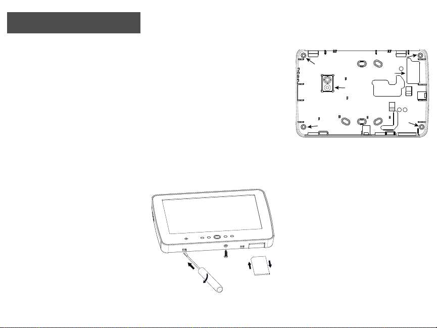
1. Retirez la carte SD avant d'ouvrir l'écran tactile (voir la
Figure 1).
AVERTISSEMENT : Démonter l'écran tactile
sans retirer préalablement la carte SD
endommage l'appareil.
2. Déposez la vis en bas du clavier.
3. Insérez un tournevis dans les logements et soulevez pour
retirer le couvercle.
Figure 1 – Dépose de la plaque arrière
4. Fixez la plaque arrière du clavier au mur en utilisant les
trous de montage. (Voir la Figure 2). Utilisez les 4 vis
fournies sauf en cas de montage sur un boîtier unique.
Utilisez les chevilles en plastique fournies pour monter
l'appareil sur une cloison sèche. Si vous utilisez
l'autoprotection du clavier, fixez la plaque correspondante
au mur avec une vis.
Figure 2 – Montage de la plaque arrière
5. Passez le fil dans le logement de câblage. Connectez le
câblage du keybus au clavier (voir la section Câblage).
6. Placez le clavier dans la plaque arrière, en veillant
à repousser le fil vers le mur autant que possible. Passez le
fil à l'intérieur du clavier en prenant soin d'éviter les
composants hauts. Enclenchez la façade pour fermer en
veillant à ce que le fil de dessous n'exerce pas de pression
sur le clavier.
NOTE: En cas de tension entre la façade du
clavier et le câblage, ouvrez le clavier, repassez le fil et refermez. Répétez ces étapes
jusqu'à ce que le clavier soit correctement
fermé.
Câblage
1. Avant de câbler l'appareil, vérifiez que toutes les
alimentations (transformateur CA, réseau de
télécommunication et batterie) sont débranchées de la
centrale de commande.
2. Branchez les quatre fils du Keybus entre la centrale de
commande (vert, jaune, noir, et rouge) aux bornes du
clavier. Consultez la Figure 3.
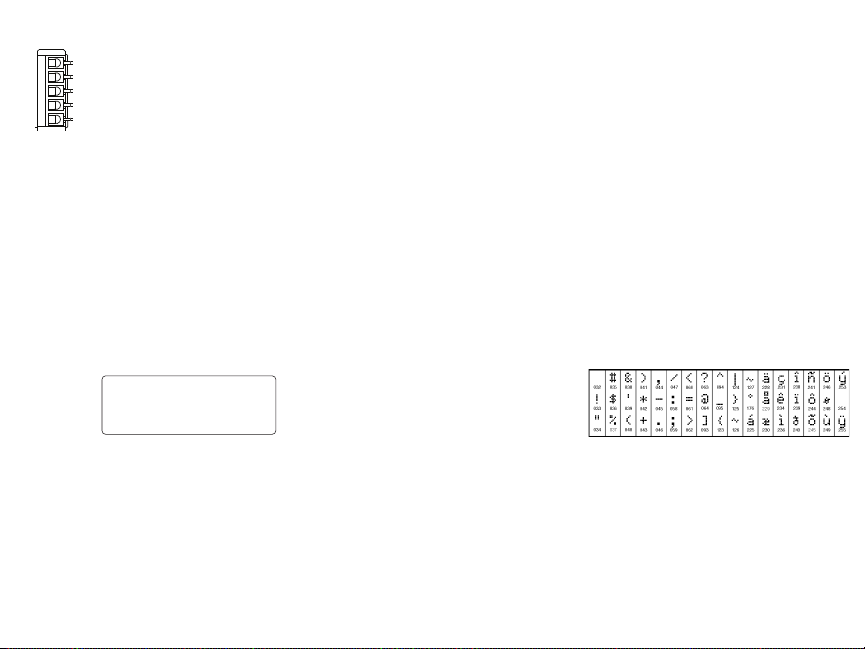
Figure 3 – Câblage
PTK5507
VERT
JAUNE
NOIR
ROUGE
INUTILISÉ
Toggle Option
1 _ _ 4 _ _ _ _
Mise sous tension
Une fois le câblage terminé et l'équipement fixé à la structure du
bâtiment avec au moins deux vis, mettez la centrale de commande
sous tension :
1. Branchez les fils de la batterie à cette dernière.
2. Branchez le transformateur CA.
3. Connectez le réseau de télécommunication (par exemple,
ligne téléphonique, câble Ethernet, etc.).
Consultez le manuel d'installation de la centrale de commande pour
des informations plus détaillées sur les spécifications électriques de
la centrale de commande.
ATTENTION : Acheminez l'ensemble du
câblage conformément aux codes et
réglementations locaux.
Paramétrage du clavier
Plusieurs options
de paramétrage
du clavier sont
disponibles. Elles
sont décrites cidessous. Le paramétrage du clavier est similaire à celui du reste du
système. Dans les sections de paramétrage du clavier, ce dernier
affiche les options activées. Pour activer ou désactiver une option,
appuyez sur le chiffre correspondant à l'option sur le pavé
numérique.
Le nombre d'options actuellement activées est affiché. Par exemple,
si les options 1 et 4 sont activées, l'affichage présente l'aspect
indiqué dans le diagramme.
Consultez le manuel d'installation pour des informations plus
détaillées sur le paramétrage du reste de votre système de sécurité.
NOTE: N'activez pas l'effacement du clavier
(paramétrage de la centrale, section 016,
option 3). Si l'effacement du clavier est
activé, la centrale cesse d'envoyer l'état et
celui du clavier est inexact.
Inscription du clavier
Le clavier doit être affecté à une partition et à un logement pour
utiliser la surveillance ou les zones du clavier. Les affectations du
clavier et le paramétrage des options du clavier doivent être
effectuées individuellement au niveau de chaque clavier.
Le premier chiffre de l'affectation du clavier est utilisé pour
déterminer l'affectation de la partition (1 à 8). Si vous n'utilisez pas
les partitions, saisissez [1].
Le deuxième chiffre de l'affectation du clavier sert à déterminer
l'affectation du logement pour la supervision du clavier. Un numéro
de logement différent de 1 à 8 est affecté à chaque clavier.
Saisissez les informations suivantes au niveau de chacun des claviers
installés dans le système :
1. Accédez au Paramétrage Installateur en appuyant sur
Options, Menu Installateur [Code Installateur], puis Param.
Mode clavier.
2. Appuyez sur [000] pour paramétrer le clavier.
3. Appuyez sur [0] pour l'affectation de partition et de
logement.
4. Saisissez le premier chiffre (1 à 8 pour l'affectation de
partition).
5. Saisissez le deuxième chiffre (1 à 8 pour l'affectation de
logement).
6. Appuyez deux fois sur la touche [#] pour quitter le
paramétrage.
7. Une fois tous les claviers affectés, effectuez une
réinitialisation supervisée en accédant à Options, Menu
Installateur, [Code Installateur], [902], et attendez 60
secondes.
8. Appuyez sur la touche [#] pour quitter le paramétrage
après 60 secondes.
Paramétrage des textes
1. Accédez à Options, Menu Installateur [Code Installateur],
puis Paramétrage texte.
2. Sélectionnez le texte à paramétrer.
3. En utilisant le clavier à l'écran, saisissez le nouveau texte et
appuyez sur Sauvegarder une fois l'opération terminée.
Diffusion des textes LCD
Tout le paramétrage LCD est effectué par clavier. En présence de
plusieurs claviers LCD dans le système, les textes paramétrés au
niveau d'un clavier peuvent être diffusés à tous les autres. Procédez
comme suit pour diffuser les textes :
Étape 1 – Paramétrez entièrement un clavier LCD.
Étape 2 – Vérifiez que tous les claviers LCD sont connectés au
Keybus.
Étape 3 – Accédez au paramétrage du clavier en appuyant sur
Options, Menu Installateur [Code Installateur], Param. Mode Clavier,
puis à la section [
diffuse toutes les informations paramétrées à tous les autres claviers
LCD du système.
Étape 4 – Lorsque le clavier a terminé, appuyez sur la touche [#]
pour quitter.
Caractères ASCII
,
] [998] [,] sur le clavier paramétré. Le clavier
 Loading...