

DSC PowerSeries PC1404 V1.1 Installation Manual

3&Y
Installation Guide
WARNING: This manual contains information on limitations regarding product use and function
and information on the limitations as to liability of the manufacturer. The entire manual should
be carefully read.

SAFETY INSTRUCTIONS for SERVICE PERSONNEL
WARNING: When using equipment connected to the TELEPHONE NETWORK, there are basic safety instructions that should
always be followed. Refer to the SAFETY INSTRUCTIONS provided with this product; save them for (future) reference. Instruct the
end-user regarding the safety precautions that shall be observed when operating this equipment.
%HIRUH,QVWDOOLQJ7KH(TXLSPHQW
Ensure your package includes the following items:
• Installation and User Manuals
• PC1404 alarm controller
• Power supply, direct plug-in
• Mounting hardware
READ and SAVE These Instructions!
Follow All WARNINGS AND INSTRUCTIONS specified within this document and/or on the equipment.
6HOHFWLQJ$6XLWDEOH/RFDWLRQ)RU7KH$ODUP&RQWUROOHU
Use the following list as a guide to find a suitable place for this equipment:
• Locate near a telephone socket and power outlet.
• Select a place free from vibration and shocks.
• Place the alarm controller on a flat, stable surface and follow the installation instructions.
DO NOT locate this product where persons may walk on the secondary circuit cable(s).
DO NOT connect the alarm controller to electrical outlets on the same circuit as large appliances.
DO NOT select a place that exposes your alarm controller to direct sunlight, excessive heat, moisture, vapors, chemicals or dust.
DO NOT install this equipment near water. (e.g., bath tub, wash bowl, kitchen/laundry sink, wet basement, near a swimming pool).
DO NOT install this equipment and its accessories in areas where there is a risk of explosion.
DO NOT connect this equipment to electrical outlets controlled by wall switches or automatic timers;
AVOID interference sources.
AVOID setting up the equipment near heaters, air conditioners, ventilators, and/or refrigerators.
AVOID locating this equipment close to or on top of large metal objects (e.g., metal wall studs).
6$)(7<3UHFDXWLRQV5HTXLUHG'XULQJ,QVWDOODWLRQ
• NEVER install this equipment and/or telephone wiring during a lightning storm.
• NEVER touch uninsulated telephone wires or terminals unless the telephone line has been disconnected at the network interface.
• Position cables so that accidents cannot occur. Connected cables must NOT be subject to excessive mechanical strain.
• Use only the power supply provided with this equipment. Use of unauthorized power supplies may cause damage.
• For direct plug-in versions, use the transformer supplied with the device.
WARNING: THIS EQUIPMENT, WHEN POWERED VIA DIRECT PLUG-IN TRANSFORMER, HAS NO MAINS ON/OFF SWITCH.
THE PLUG OF THE DIRECT PLUG-IN POWER SUPPLY IS INTENDED TO SERVE AS THE DISCONNECTING DEVICE IF THE
EQUIPMENT MUST BE QUICKLY DISCONNECTED. IT IS IMPERATIVE THAT ACCESS TO THE MAINS PLUG AND ASSOCI-
ATED MAINS SOCKET/OUTLET IS NEVER OBSTRUCTED.
IMPORTANT NOTE!
7KLV equipment, alarm controller PC1404, VKDOO EH LQVWDOOHG DQG
XVHG ZLWKLQ DQ HQYLURQPHQW WKDW SURYLGHV WKH SROOXWLRQ GHJUHH PD[
DQG RYHUYROWDJHV FDWHJRU\ ,, 121+$=$5'286 /2&$7,216
LQGRRU RQO\ 7KH HTXLSPHQW LV FIXED and 3(50$1(17/< &21
1(&7(' DQG LV GHVLJQHG WR EH LQVWDOOHG VHUYLFHG DQGRU UHSDLUHG
E\ VHUYLFH SHUVRQV RQO\ >VHUYLFH SHUVRQ LV GHILQHG DV D SHUVRQ
KDYLQJ WKH DSSURSULDWH WHFKQLFDO WUDLQLQJ DQG H[SHULHQFH QHFHVVDU\
WR EH DZDUH RI KD]DUGV WR ZKLFK WKDW SHUVRQ PD\ EH H[SRVHG LQ
SHUIRUPLQJ D WDVN DQG RI PHDVXUHV WR PLQLPL]H WKH ULVNV WR WKDW
SHUVRQ RU RWKHU SHUVRQV@ 7KHUH DUH QR SDUWV UHSODFHDEOH E\ WKH
HQGXVHU ZLWKLQ WKLV HTXLSPHQW 7KH ZLULQJ FDEOHV XVHG IRU
LQVWDOODWLRQ RI WKH $ODUP 6\VWHP DQG DFFHVVRULHV VKDOO EH LQVXODWHG
ZLWK39&7)(37)()(31HRSUHQHRU3RO\DPLGH
a) The equipment enclosure must be secured to the building
structure before operation.
b) Internal wiring must be routed in a manner that prevents
- excessive strain or loosening of wire on terminal connections;
7KH SRZHU VXSSO\ PXVW EH &ODVV ,, )$,/ 6$)( ZLWK GRXEOH RU UHLQIRUFHG LQVXODWLRQ EHWZHHQ WKH 35,0$5< DQG 6(&21'$5< FLUFXLW
(1&/2685(DQGEHDQDSSURYHGW\SHDFFHSWDEOHWRWKHORFDODXWKRULWLHV$OOQDWLRQDOZLULQJUXOHVVKDOOEHREVHUYHG
- damage of conductor insulation.
c) Disposal of used batteries shall be made in accordance with
local waste recovery and recycling regulations.
d) Before servicing, DISCONNECT the power and telephone
connection.
e) DO NOT route any wiring over circuit boards. Maintain at
least 1” (25.4 mm) separation.
f) It is the installer’s responsibility to ensure that a readily
accessible disconnect device is incorporated in the building for
permanently connected installations.
g) The connection to the mains supply must be made as per
the local authorities’ rules and regulations. An appropriate disconnect device must be provided as part of the building installation. Where it is not possible to rely on identification of the
neutral in the AC Mains supply, the disconnecting device must
disconnect both poles simultaneously (line and neutral). The
device shall disconnect the supply during servicing.
i
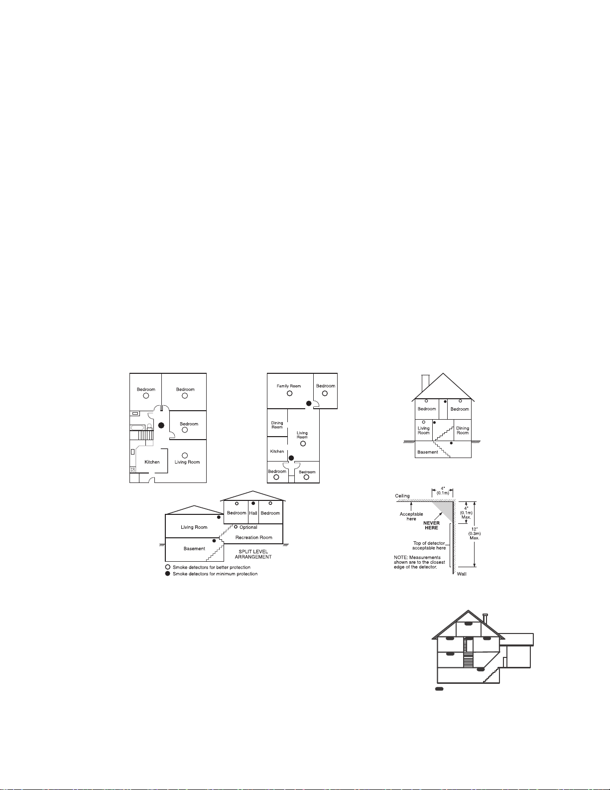
*XLGHOLQHVIRU/RFDWLQJ6PRNH&2'HWHFWRUV
The following information is for general guidance only and it is recommended that local fire codes and regulations be consulted when
locating and installing smoke and CO alarms.
6PRNH'HWHFWRUV
Research indicates that all hostile fires in homes generate smoke to a greater or lesser extent. Detectable quantities of smoke precede
detectable levels of heat in most cases. Smoke alarms should be installed outside of each sleeping area and on each storey of the home.
DSC recommends that additional smoke alarms beyond those required for minimum protection be installed. Additional areas that
should be protected include: the basement; bedrooms, especially where smokers sleep; dining rooms; furnace and utility rooms; and
any hallways not protected by the required units.
On smooth ceilings, detectors may be spaced 9.1m (30 feet) apart as a guide. Other spacing may be required depending on ceiling
height, air movement, the presence of joists, uninsulated ceilings, etc. Consult National Fire Alarm Code NFPA 72, CAN/ULC-S55302 or other appropriate national standards for installation recommendations.
• Do not locate smoke detectors at the top of peaked or gabled ceilings; dead air space in these locations may prevent smoke detection.
• Avoid areas with turbulent air flow, such as near doors, fans or windows. Rapid air movement around the detector may prevent
smoke from entering the unit.
• Do not locate detectors in areas of high humidity.
• Do not locate detectors in areas where the temperature rises above 38
Smoke detectors should always be installed in USA in accordance with Chapter 29 of NFPA 72, the National Fire Alarm Code: 29.5.1.1.
Where required by other governing laws, codes, or standards for a specific type of occupancy, approved single- and multiple-station
smoke alarms shall be installed as follows:
(1) In all sleeping rooms and guest rooms.
(2) Outside of each separate dwelling unit sleeping area, within 21 ft (6.4 m) of any door to a sleeping room, with the distance mea-
sured along a path of travel.
(3) On every level of a dwelling unit, including basements.
(4) On every level of a residential board and care occupancy (small facility), including basements and excluding crawl spaces and
unfinished attics.
(5) In the living area(s) of a guest suite.
(6) In the living area(s) of a residential board and care occupancy (small facility).
oC
(100oF) or falls below 5oC (41oF).
Figure 1
Figure 3a
Figure 2
&2'HWHFWRUV
CO gas moves freely in the air. The human body is most vulnerable to the effects of CO gas during
sleeping hours. For maximum protection, a CO alarm should be located outside primary sleeping
areas or on each level of your home. Figure 5 indicates the suggested locations in the home. The
electronic sensor detects carbon monoxide, measures the concentration and sounds a loud alarm
before a potentially harmful level is reached.
Do NOT place the CO alarm in the following areas:
• Where the temperature may drop below -10ºC or exceed 40 ºC.
• Near paint thinner fumes.
• Within 5 feet (1.5 meters) of open flame appliances such as furnaces, stoves and fireplaces.
• In exhaust streams from gas engines, vents, flues or chimneys.
• Do not place in close proximity to an automobile exhaust pipe; this will damage the detector.
Figure 3
Figure 4
BEDROOM
BEDROOM
GROUND
FLOOR
BASEMEN T
CARBON MONO XIDE DETECTOR
Figure 5
BEDROOM
KITCHEN
GARAGE
LL

Digital Security Controls warrants the original purchaser that for a period of twelve months from the date of purchase, the product shall be free of defects in materials and
Limited Warranty
workmanship under normal use. During the warranty period, Digital Security Controls shall, at its option, repair or replace any defective product upon return of the product to
its factory, at no charge for labour and materials. Any replacement and/or repaired parts are warranted for the remainder of the original warranty or ninety (90) days, whichever
is longer. The original purchaser must promptly notify Digital Security Controls in writing that there is defect in material or workmanship, such written notice to be received in
all events prior to expiration of the warranty period. There is absolutely no warranty on software and all software products are sold as a user license under the terms of the
software license agreement included with the product. The Customer assumes all responsibility for the proper selection, installation, operation and maintenance of any
products purchased from DSC. Custom products are only warranted to the extent that they do not function upon delivery. In such cases, DSC can replace or credit at its option.
International Warranty
The warranty for international customers is the same as for any customer within Canada and the United States, with the exception that Digital Security Controls shall not be
responsible for any customs fees, taxes, or VAT that may be due.
Warranty Procedure
To obtain service under this warranty, please return the item(s) in question to the point of purchase. All authorized distributors and dealers have a warranty program. Anyone
returning goods to Digital Security Controls must first obtain an authorization number. Digital Security Controls will not accept any shipment whatsoever for which prior
authorization has not been obtained.
Conditions to Void Warranty
This warranty applies only to defects in parts and workmanship relating to normal use. It does not cover:
• damage incurred in shipping or handling;
• damage caused by disaster such as fire, flood, wind, earthquake or lightning;
• damage due to causes beyond the control of Digital Security Controls such as excessive voltage, mechanical shock or water damage;
• damage caused by unauthorized attachment, alterations, modifications or foreign objects;
• damage caused by peripherals (unless such peripherals were supplied by Digital Security Controls Ltd.);
• defects caused by failure to provide a suitable installation environment for the products;
• damage caused by use of the products for purposes other than those for which it was designed;
• damage from improper maintenance;
• damage arising out of any other abuse, mishandling or improper application of the products.
WARNING - READ CAREFULLY
Note to Installers
This warning contains vital information. As the only individual in contact with system users, it is your responsibility to bring each item in this warning to the attention of the
users of this system.
System Failures
This system has been carefully designed to be as effective as possible. There are circumstances, however, involving fire, burglary, or other types of emergencies where it may
not provide protection. Any alarm system of any type may be compromised deliberately or may fail to operate as expected for a variety of reasons. Some but not all of these
reasons may be:
• Inadequate Installation
A security system must be installed properly in order to provide adequate protection. Every installation should be evaluated by a security professional to ensure that all access
points and areas are covered. Locks and latches on windows and doors must be secure and operate as intended. Windows, doors, walls, ceilings and other building materials
must be of sufficient strength and construction to provide the level of protection expected. A reevaluation must be done during and after any construction activity. An evaluation
by the fire and/or police department is highly recommended if this service is available.
• Criminal Knowledge
This system contains security features which were known to be effective at the time of manufacture. It is possible for persons with criminal intent to develop techniques which
reduce the effectiveness of these features. It is important that a security system be reviewed periodically to ensure that its features remain effective and that it be updated or
replaced if it is found that it does not provide the protection expected.
• Access by Intruders
Intruders may enter through an unprotected access point, circumvent a sensing device, evade detection by moving through an area of insufficient coverage, disconnect a
warning device, or interfere with or prevent the proper operation of the system.
• Power Failure
Control units, intrusion detectors, smoke detectors and many other security devices require an adequate power supply for proper operation. If a device operates from batteries,
it is possible for the batteries to fail. Even if the batteries have not failed, they must be charged, in good condition and installed correctly. If a device operates only by AC power,
any interruption, however brief, will render that device inoperative while it does not have power. Power interruptions of any length are often accompanied by voltage
fluctuations which may damage electronic equipment such as a security system. After a power interruption has occurred, immediately conduct a complete system test to
ensure that the system operates as intended.
• Failure of Replaceable Batteries
This system’s wireless transmitters have been designed to provide several years of battery life under normal conditions. The expected battery life is a function of the device
environment, usage and type. Ambient conditions such as high humidity, high or low temperatures, or large temperature fluctuations may reduce the expected battery life.
While each transmitting device has a low battery monitor which identifies when the batteries need to be replaced, this monitor may fail to operate as expected. Regular testing
and maintenance will keep the system in good operating condition.
• Compromise of Radio Frequency (Wireless) Devices
Signals may not reach the receiver under all circumstances which could include metal objects placed on or near the radio path or deliberate jamming or other inadvertent
radio signal interference.
• System Users
A user may not be able to operate a panic or emergency switch possibly due to permanent or temporary physical disability, inability to reach the device in time, or unfamiliarity
with the correct operation. It is important that all system users be trained in the correct operation of the alarm system and that they know how to respond when the system
indicates an alarm.
IMPORTANT - READ CAREFULLY: DSC Software purchased with or without Products and Components
• This End-User License Agreement (“EULA”) is a legal agreement between You (the company, individual or entity who acquired the Software and any
related Hardware) and Digital Security Controls, a division of Tyco Safety Products Canada Ltd. (“DSC”), the manufacturer of the integrated security
systems and the developer of the software and any related products or components (“HARDWARE”) which You acquired.
• If the DSC software product (“SOFTWARE PRODUCT” or “SOFTWARE”) is intended to be accompanied by HARDWARE, and is NOT accompanied by
new HARDWARE, You may not use, copy or install the SOFTWARE PRODUCT. The SOFTWARE PRODUCT includes computer software, and may
include associated media, printed materials, and “online” or electronic documentation.
• Any software provided along with the SOFTWARE PRODUCT that is associated with a separate end-user license agreement is licensed to You under the
terms of that license agreement.
• By installing, copying, downloading, storing, accessing or otherwise using the SOFTWARE PRODUCT, You agree unconditionally to be bound by the
terms of this EULA, even if this EULA is deemed to be a modification of any previous arrangement or contract. If You do not agree to the terms of this
EULA, DSC is unwilling to license the SOFTWARE PRODUCT to You, and You have no right to use it.
SOFTWARE PRODUCT LICENSE
The SOFTWARE PRODUCT is protected by copyright laws and international copyright treaties, as well as other intellectual property laws and treaties. The
SOFTWARE PRODUCT is licensed, not sold.
1.GRANT OF LICENSE This EULA grants You the following rights:
(a) Software Installation and Use - For each license You acquire, You may have only one copy of the SOFTWARE PRODUCT installed.
(b) Storage/Network Use - The SOFTWARE PRODUCT may not be installed, accessed, displayed, run, shared or used concurrently on or from different
computers, including a workstation, terminal or other digital electronic device (“Device”). In other words, if You have several workstations, You will
have to acquire a license for each workstation where the SOFTWARE will be used.
(c) Backup Copy - You may make back-up copies of the SOFTWARE PRODUCT, but You may only have one copy per license installed at any given time.
You may use the back-up copy solely for archival purposes. Except as expressly provided in this EULA, You may not otherwise make copies of the
SOFTWARE PRODUCT, including the printed materials accompanying the SOFTWARE.
2. DESCRIPTION OF OTHER RIGHTS AND LIMITATIONS
(a) Limitations on Reverse Engineering, Decompilation and Disassembly - You may not reverse engineer, decompile, or disassemble the SOFTWARE
PRODUCT, except and only to the extent that such activity is expressly permitted by applicable law notwithstanding this limitation. You may not make any
changes or modifications to the Software, without the written permission of an officer of DSC. You may not remove any proprietary notices, marks or
labels from the Software Product. You shall institute reasonable measures to ensure compliance with the terms and conditions of this EULA.
(b) Separation of Components - The SOFTWARE PRODUCT is licensed as a single product. Its component parts may not be separated for use on more
than one HARDWARE unit.
(c) Single INTEGRATED PRODUCT - If You acquired this SOFTWARE with HARDWARE, then the SOFTWARE PRODUCT is licensed with the HARDWARE
as a single integrated product. In this case, the SOFTWARE PRODUCT may only be used with the HARDWARE as set forth in this EULA.
(d) Rental - You may not rent, lease or lend the SOFTWARE PRODUCT. You may not make it available to others or post it on a server or web site.
(e) Software Product Transfer - You may transfer all of Your rights under this EULA only as part of a permanent sale or transfer of the HARDWARE,
provided You retain no copies, You transfer all of the SOFTWARE PRODUCT (including all component parts, the media and printed materials, any
upgrades and this EULA), and provided the recipient agrees to the terms of this EULA. If the SOFTWARE PRODUCT is an upgrade, any transfer must
also include all prior versions of the SOFTWARE PRODUCT.
is copyrighted and is purchased under the following license terms:
Items Not Covered by Warranty
In addition to the items which void the Warranty, the following items shall not be covered by Warranty: (i) freight cost to the repair centre; (ii) products which are not identified
with DSC's product label and lot number or serial number; (iii) products disassembled or repaired in such a manner as to adversely affect performance or prevent adequate
inspection or testing to verify any warranty claim. Access cards or tags returned for replacement under warranty will be credited or replaced at DSC's option. Products not
covered by this warranty, or otherwise out of warranty due to age, misuse, or damage shall be evaluated, and a repair estimate shall be provided. No repair work will be
performed until a valid purchase order is received from the Customer and a Return Merchandise Authorization number (RMA) is issued by DSC's Customer Service.
Digital Security Controls Ltd.’s liability for failure to repair the product under this warranty after a reasonable number of attempts will be limited to a replacement of the product,
as the exclusive remedy for breach of warranty. Under no circumstances shall Digital Security Controls be liable for any special, incidental, or consequential damages based
upon breach of warranty, breach of contract, negligence, strict liability, or any other legal theory. Such damages include, but are not limited to, loss of profits, loss of the
product or any associated equipment, cost of capital, cost of substitute or replacement equipment, facilities or services, down time, purchaser’s time, the claims of third
parties, including customers, and injury to property. The laws of some jurisdictions limit or do not allow the disclaimer of consequential damages. If the laws of such a
jurisdiction apply to any claim by or against DSC, the limitations and disclaimers contained here shall be to the greatest extent permitted by law. Some states do not allow the
exclusion or limitation of incidental or consequential damages, so that the above may not apply to you.
Disclaimer of Warranties
This warranty contains the entire warranty and shall be in lieu of any and all other warranties, whether expressed or implied (including all implied warranties of merchantability
or fitness for a particular purpose) and of all other obligations or liabilities on the part of Digital Security Controls. Digital Security Controls neither assumes responsibility for,
nor authorizes any other person purporting to act on its behalf to modify or to change this warranty, nor to assume for it any other warranty or liability concerning this product.
This disclaimer of warranties and limited warranty are governed by the laws of the province of Ontario, Canada.
WARNING: Digital Security Controls recommends that the entire system be completely tested on a regular basis. However, despite frequent
testing, and due to, but not limited to, criminal tampering or electrical disruption, it is possible for this product to fail to perform as expected.
Out of Warranty Repairs
Digital Security Controls will at its option repair or replace out-of-warranty products which are returned to its factory according to the following conditions. Anyone returning
goods to Digital Security Controls must first obtain an authorization number. Digital Security Controls will not accept any shipment whatsoever for which prior authorization has
not been obtained.
Products which Digital Security Controls determines to be repairable will be repaired and returned. A set fee which Digital Security Controls has predetermined and which may
be revised from time to time, will be charged for each unit repaired.
Products which Digital Security Controls determines not to be repairable will be replaced by the nearest equivalent product available at that time. The current market price of
the replacement product will be charged for each replacement unit.
• Smoke Detectors
Smoke detectors that are a part of this system may not properly alert occupants of a fire for a number of reasons, some of which follow. The smoke detectors may have been
improperly installed or positioned. Smoke may not be able to reach the smoke detectors, such as when the fire is in a chimney, walls or roofs, or on the other side of closed
doors. Smoke detectors may not detect smoke from fires on another level of the residence or building.
Every fire is different in the amount of smoke produced and the rate of burning. Smoke detectors cannot sense all types of fires equally well. Smoke detectors may not provide
timely warning of fires caused by carelessness or safety hazards such as smoking in bed, violent explosions, escaping gas, improper storage of flammable materials,
overloaded electrical circuits, children playing with matches or arson.
Even if the smoke detector operates as intended, there may be circumstances when there is insufficient warning to allow all occupants to escape in time to avoid injury or death.
• Motion Detectors
Motion detectors can only detect motion within the designated areas as shown in their respective installation instructions. They cannot discriminate between intruders and
intended occupants. Motion detectors do not provide volumetric area protection. They have multiple beams of detection and motion can only be detected in unobstructed
areas covered by these beams. They cannot detect motion which occurs behind walls, ceilings, floor, closed doors, glass partitions, glass doors or windows. Any type of
tampering whether intentional or unintentional such as masking, painting, or spraying of any material on the lenses, mirrors, windows or any other part of the detection system
will impair its proper operation.
Passive infrared motion detectors operate by sensing changes in temperature. However their effectiveness can be reduced when the ambient temperature rises near or above
body temperature or if there are intentional or unintentional sources of heat in or near the detection area. Some of these heat sources could be heaters, radiators, stoves,
barbeques, fireplaces, sunlight, steam vents, lighting and so on.
• Warning Devices
Warning devices such as sirens, bells, horns, or strobes may not warn people or waken someone sleeping if there is an intervening wall or door. If warning devices are located
on a different level of the residence or premise, then it is less likely that the occupants will be alerted or awakened. Audible warning devices may be interfered with by other
noise sources such as stereos, radios, televisions, air conditioners or other appliances, or passing traffic. Audible warning devices, however loud, may not be heard by a
hearing-impaired person.
• Telephone Lines
If telephone lines are used to transmit alarms, they may be out of service or busy for certain periods of time. Also an intruder may cut the telephone line or defeat its operation
by more sophisticated means which may be difficult to detect.
• Insufficient Time
There may be circumstances when the system will operate as intended, yet the occupants will not be protected from the emergency due to their inability to respond to the
warnings in a timely manner. If the system is monitored, the response may not occur in time to protect the occupants or their belongings.
• Component Failure
Although every effort has been made to make this system as reliable as possible, the system may fail to function as intended due to the failure of a component.
• Inadequate Testing
Most problems that would prevent an alarm system from operating as intended can be found by regular testing and maintenance. The complete system should be tested
weekly and immediately after a break-in, an attempted break-in, a fire, a storm, an earthquake, an accident, or any kind of construction activity inside or outside the premises.
The testing should include all sensing devices, keypads, consoles, alarm indicating devices and any other operational devices that are part of the system.
•Security and Insurance
Regardless of its capabilities, an alarm system is not a substitute for property or life insurance. An alarm system also is not a substitute for property owners, renters, or other
occupants to act prudently to prevent or minimize the harmful effects of an emergency situation.
(f) Termination - Without prejudice to any other rights, DSC may terminate this EULA if You fail to comply with the terms and conditions of this EULA.
In such event, You must destroy all copies of the SOFTWARE PRODUCT and all of its component parts.
(g) Trademarks - This EULA does not grant You any rights in connection with any trademarks or service marks of DSC or its suppliers.
3. COPYRIGHT - All title and intellectual property rights in and to the SOFTWARE PRODUCT (including but not limited to any images, photographs, and
text incorporated into the SOFTWARE PRODUCT), the accompanying printed materials, and any copies of the SOFTWARE PRODUCT, are owned by DSC
or its suppliers. You may not copy the printed materials accompanying the SOFTWARE PRODUCT. All title and intellectual property rights in and to the
content which may be accessed through use of the SOFTWARE PRODUCT are the property of the respective content owner and may be protected by
applicable copyright or other intellectual property laws and treaties. This EULA grants You no rights to use such content. All rights not expressly granted
under this EULA are reserved by DSC and its suppliers.
4. EXPORT RESTRICTIONS - You agree that You will not export or re-export the SOFTWARE PRODUCT to any country, person, or entity subject to
Canadian export restrictions.
5. CHOICE OF LAW - This Software License Agreement is governed by the laws of the Province of Ontario, Canada.
6. ARBITRATION - All disputes arising in connection with this Agreement shall be determined by final and binding arbitration in accordance with the
Arbitration Act, and the parties agree to be bound by the arbitrator’s decision. The place of arbitration shall be Toronto, Canada, and the language of the
arbitration shall be English.
7. LIMITED WARRANTY
(a) NO WARRANTY - DSC PROVIDES THE SOFTWARE “AS IS” WITHOUT WARRANTY. DSC DOES NOT WARRANT THAT THE SOFTWARE WILL MEET YOUR
REQUIREMENTS OR THAT OPERATION OF THE SOFTWARE WILL BE UNINTERRUPTED OR ERROR-FREE.
(b) CHANGES IN OPERATING ENVIRONMENT - DSC shall not be responsible for problems caused by changes in the operating characteristics of the
HARDWARE, or for problems in the interaction of the SOFTWARE PRODUCT with non-DSC-SOFTWARE or HARDWARE PRODUCTS.
(c) LIMITATION OF LIABILITY; WARRANTY REFLECTS ALLOCATION OF RISK - IN ANY EVENT, IF ANY STATUTE IMPLIES WARRANTIES OR CONDITIONS
NOT STATED IN THIS LICENSE AGREEMENT, DSC’S ENTIRE LIABILITY UNDER ANY PROVISION OF THIS LICENSE AGREEMENT SHALL BE LIMITED
TO THE GREATER OF THE AMOUNT ACTUALLY PAID BY YOU TO LICENSE THE SOFTWARE PRODUCT AND FIVE CANADIAN DOLLARS (CAD$5.00).
BECAUSE SOME JURISDICTIONS DO NOT ALLOW THE EXCLUSION OR LIMITATION OF LIABILITY FOR CONSEQUENTIAL OR INCIDENTAL
DAMAGES, THE ABOVE LIMITATION MAY NOT APPLY TO YOU.
(d) DISCLAIMER OF WARRANTIES - THIS WARRANTY CONTAINS THE ENTIRE WARRANTY AND SHALL BE IN LIEU OF ANY AND ALL OTHER
WARRANTIES, WHETHER EXPRESSED OR IMPLIED (INCLUDING ALL IMPLIED WARRANTIES OF MERCHANTABILITY OR FITNESS FOR A
PARTICULAR PURPOSE) AND OF ALL OTHER OBLIGATIONS OR LIABILITIES ON THE PART OF DSC. DSC MAKES NO OTHER WARRANTIES. DSC
NEITHER ASSUMES NOR AUTHORIZES ANY OTHER PERSON PURPORTING TO ACT ON ITS BEHALF TO MODIFY OR TO CHANGE THIS WARRANTY,
NOR TO ASSUME FOR IT ANY OTHER WARRANTY OR LIABILITY CONCERNING THIS SOFTWARE PRODUCT.
(e) EXCLUSIVE REMEDY AND LIMITATION OF WARRANTY - UNDER NO CIRCUMSTANCES SHALL DSC BE LIABLE FOR ANY SPECIAL, INCIDENTAL,
CONSEQUENTIAL OR INDIRECT DAMAGES BASED UPON BREACH OF WARRANTY, BREACH OF CONTRACT, NEGLIGENCE, STRICT LIABILITY, OR
ANY OTHER LEGAL THEORY. SUCH DAMAGES INCLUDE, BUT ARE NOT LIMITED TO, LOSS OF PROFITS, LOSS OF THE SOFTWARE PRODUCT OR
ANY ASSOCIATED EQUIPMENT, COST OF CAPITAL, COST OF SUBSTITUTE OR REPLACEMENT EQUIPMENT, FACILITIES OR SERVICES, DOWN
TIME, PURCHASERS TIME, THE CLAIMS OF THIRD PARTIES, INCLUDING CUSTOMERS, AND INJURY TO PROPERTY.
WARNING: DSC recommends that the entire system be completely tested on a regular basis. However, despite frequent testing, and due to,
but not limited to, criminal tampering or electrical disruption, it is possible for this SOFTWARE PRODUCT to fail to perform as expected.
LLL

Table of Contents
SAFETY INSTRUCTIONS for SERVICE PERSONNEL . . . . . . . . . . . . . . . . . . . . . . . . . . . . . . . . . . . . . ii
1 Introduction . . . . . . . . . . . . . . . . . . . . . . . . . . . . . . . . . . . . . . . . . . . . . . . . . . . . . . . . . . . . . . . . . . . . . . . . 1
1.1 Compatibility Requirements . . . . . . . . . . . . . . . . . . . . . . . . . . . . . . . . . . . . . . . . . . . . . . . . . . . . . . . . . . 1
1.2 Product Specifications . . . . . . . . . . . . . . . . . . . . . . . . . . . . . . . . . . . . . . . . . . . . . . . . . . . . . . . . . . . . . . 1
1.3 Out of the Box. . . . . . . . . . . . . . . . . . . . . . . . . . . . . . . . . . . . . . . . . . . . . . . . . . . . . . . . . . . . . . . . . . . . . 2
2 Installation . . . . . . . . . . . . . . . . . . . . . . . . . . . . . . . . . . . . . . . . . . . . . . . . . . . . . . . . . . . . . . . . . . . . . . . . . 3
2.1 Installation Steps. . . . . . . . . . . . . . . . . . . . . . . . . . . . . . . . . . . . . . . . . . . . . . . . . . . . . . . . . . . . . . . . . . . 3
2.2 Terminal Descriptions. . . . . . . . . . . . . . . . . . . . . . . . . . . . . . . . . . . . . . . . . . . . . . . . . . . . . . . . . . . . . . . 3
2.3 Wire Routing for Power & Non-Power Limited. . . . . . . . . . . . . . . . . . . . . . . . . . . . . . . . . . . . . . . . . . . 4
2.4 Keybus Operation and Wiring . . . . . . . . . . . . . . . . . . . . . . . . . . . . . . . . . . . . . . . . . . . . . . . . . . . . . . . . 4
2.5 Current Ratings – Modules & Accessories . . . . . . . . . . . . . . . . . . . . . . . . . . . . . . . . . . . . . . . . . . . . . . 5
2.6 Keypad Assignment . . . . . . . . . . . . . . . . . . . . . . . . . . . . . . . . . . . . . . . . . . . . . . . . . . . . . . . . . . . . . . . . 5
2.7 Supervision . . . . . . . . . . . . . . . . . . . . . . . . . . . . . . . . . . . . . . . . . . . . . . . . . . . . . . . . . . . . . . . . . . . . . . . 5
2.8 Removing Modules. . . . . . . . . . . . . . . . . . . . . . . . . . . . . . . . . . . . . . . . . . . . . . . . . . . . . . . . . . . . . . . . . 5
2.9 Zone Wiring . . . . . . . . . . . . . . . . . . . . . . . . . . . . . . . . . . . . . . . . . . . . . . . . . . . . . . . . . . . . . . . . . . . . . . 5
2.10 Zone Doubling . . . . . . . . . . . . . . . . . . . . . . . . . . . . . . . . . . . . . . . . . . . . . . . . . . . . . . . . . . . . . . . . . . . 6
2.11 Fire Zone Wiring . . . . . . . . . . . . . . . . . . . . . . . . . . . . . . . . . . . . . . . . . . . . . . . . . . . . . . . . . . . . . . . . . 7
2.12 CO Detector Wiring . . . . . . . . . . . . . . . . . . . . . . . . . . . . . . . . . . . . . . . . . . . . . . . . . . . . . . . . . . . . . . . 7
2.13 Keypad Zones . . . . . . . . . . . . . . . . . . . . . . . . . . . . . . . . . . . . . . . . . . . . . . . . . . . . . . . . . . . . . . . . . . . 7
3 Keypad Commands . . . . . . . . . . . . . . . . . . . . . . . . . . . . . . . . . . . . . . . . . . . . . . . . . . . . . . . . . . . . . . . . . 10
3.1 Arming and Disarming . . . . . . . . . . . . . . . . . . . . . . . . . . . . . . . . . . . . . . . . . . . . . . . . . . . . . . . . . . . . 10
3.2 Auto Bypass – Stay Arming . . . . . . . . . . . . . . . . . . . . . . . . . . . . . . . . . . . . . . . . . . . . . . . . . . . . . . . . 10
3.3 Automatic Arming . . . . . . . . . . . . . . . . . . . . . . . . . . . . . . . . . . . . . . . . . . . . . . . . . . . . . . . . . . . . . . . . 10
3.4 Night Arming . . . . . . . . . . . . . . . . . . . . . . . . . . . . . . . . . . . . . . . . . . . . . . . . . . . . . . . . . . . . . . . . . . . . 10
3.5 [*] Commands . . . . . . . . . . . . . . . . . . . . . . . . . . . . . . . . . . . . . . . . . . . . . . . . . . . . . . . . . . . . . . . . . . . 10
4 Programming . . . . . . . . . . . . . . . . . . . . . . . . . . . . . . . . . . . . . . . . . . . . . . . . . . . . . . . . . . . . . . . . . . . . . . 16
4.1 Installer Programming . . . . . . . . . . . . . . . . . . . . . . . . . . . . . . . . . . . . . . . . . . . . . . . . . . . . . . . . . . . . . 16
4.2 Programming Decimal Data . . . . . . . . . . . . . . . . . . . . . . . . . . . . . . . . . . . . . . . . . . . . . . . . . . . . . . . . 16
4.3 Programming HEX Data . . . . . . . . . . . . . . . . . . . . . . . . . . . . . . . . . . . . . . . . . . . . . . . . . . . . . . . . . . . 16
4.4 Programming Toggle Option Selections . . . . . . . . . . . . . . . . . . . . . . . . . . . . . . . . . . . . . . . . . . . . . . . 17
4.5 Viewing Programming . . . . . . . . . . . . . . . . . . . . . . . . . . . . . . . . . . . . . . . . . . . . . . . . . . . . . . . . . . . . . 17
4.6 DLS Programming . . . . . . . . . . . . . . . . . . . . . . . . . . . . . . . . . . . . . . . . . . . . . . . . . . . . . . . . . . . . . . . . 17
5 Programming Worksheets . . . . . . . . . . . . . . . . . . . . . . . . . . . . . . . . . . . . . . . . . . . . . . . . . . . . . . . . . . . . 18
5.1 Index to Programming Worksheets . . . . . . . . . . . . . . . . . . . . . . . . . . . . . . . . . . . . . . . . . . . . . . . . . . . 18
5.2 Programming Worksheets . . . . . . . . . . . . . . . . . . . . . . . . . . . . . . . . . . . . . . . . . . . . . . . . . . . . . . . . . . 19
6 Testing & Troubleshooting . . . . . . . . . . . . . . . . . . . . . . . . . . . . . . . . . . . . . . . . . . . . . . . . . . . . . . . . . . . 34
Appendix A: Reporting Code Formats . . . . . . . . . . . . . . . . . . . . . . . . . . . . . . . . . . . . . . . . . . . . . . . . . . . 37
Appendix B: Communicator Format Options . . . . . . . . . . . . . . . . . . . . . . . . . . . . . . . . . . . . . . . . . . . . . . 40
Appendix C: Regulatory Approvals Information . . . . . . . . . . . . . . . . . . . . . . . . . . . . . . . . . . . . . . . . . . . 42
Appendix D: New Zealand Addendum . . . . . . . . . . . . . . . . . . . . . . . . . . . . . . . . . . . . . . . . . . . . . . . . . . . 45
Appendix E: Australian Addendum . . . . . . . . . . . . . . . . . . . . . . . . . . . . . . . . . . . . . . . . . . . . . . . . . . . . . . 46
Appendix F: Addendum for Installations in South Africa . . . . . . . . . . . . . . . . . . . . . . . . . . . . . . . . . . . . . 48
iv
SIA-FAR Minimum System
Requirements:
1 PC1404 Panel
1 Local annunciation devices
Local annunciation devices may be
any combination of these keypads:
PK5500, PK5501, PK5508, PK5516,
PC1404RKZ, LCD5511, LED5511Z,
PC1555RKZ
Battery capacity for 4 h standby is
at least 4 Ah. Battery capacity for 24 h
standby is 7 Ah. (Max. Aux current shall
be in accordance with Section 2.2 battery
connection.) Recommended batteries:
DSC BD4-12 or DSC BD7-12.
For NA
installations
only
For EU
installations
only
Use a UL/CSA-listed Class 2 Transformer
AC
16.5V
PTD 1640 (CDN).
DO not connect transformer to
receptacle controlled by a switch.
Note: It is the installer’s responsibility to
ensure that the external PRIMARY wires
are tied together using a cable tie or
equivalent as close as possible
to the terminal block.
Applicable UL Standards
UL 985 Household Fire Warning System Units
UL1023 Household Burglar Alarm System Units
UL 1635 Digital Alarm Communicator System Units
ANSI/SIA CP-01-2010
4.0/7.0 Ah
200–350 mA
RED
BLK
40 VA DSC PTD 1640U (USA)/
PC1404 Wiring Diagram
so sI
-
-
CON1
BAT+BAT-
(NA)
(EU)
230/240 V
AC
50/60Hz
FUSE 315mA/250V
(within terminal block)
Test the alarm system at least
once per week.
UL
AUX Wiring
Use No. 14-22 AWG conductor.
Total current draw from keypads,
PGM outputs and AUX circuits must
not exceed 550mA.
.
-
BRN
T-1
GRA
R-1
GRN
TIP
RED
RING
RJ-31X
26 AWG
30
Telephone line wiring
REFER TO
MANUAL FOR
LIST OF
COMPATIBLE
DEVICES
1500
GREEN
BROWN
RED
GOLD
.
ZONE DOUBLING
2400
RED
RED
GOLD
YELLOW
LCD5511
LED5511
PC1555RKZ
PK5500/PK5501
PK5508/PK5516
PC1404RKZ
EOLR-2
END-OF-LINE
RESISTOR
5600 Ohm, 0.5W
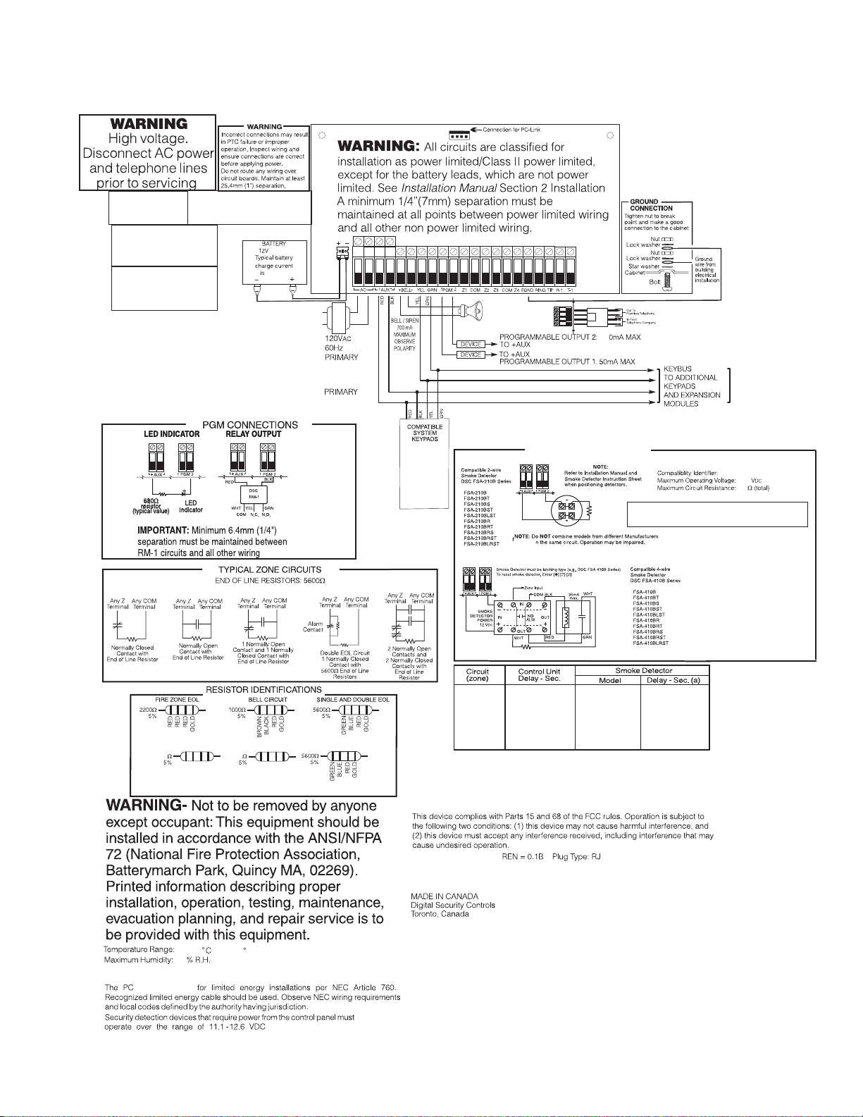
(a) The delay (power-up) time marked on the installation wiring diagram of the smoke detector
or on the installed smoke detector(s) is to be used. Control panel is suitable for the following
UL installations:
2-WIRE SMOKE DETECTORS
2200 Ohm
END-OF-LINE
RESISTOR
EOLR-3
o
4-WIRE SMOKE DETECTORS
RM-1/RM-2 POWER LOOP
SUPERVISORY RELAY
12V
DC
ALARM
INITIATING
LOOP
RESISTANCE
100 Ohm
MODEL MAX # BASECOMPATIBILITY ID
NAME
FSA-210B Series
DSC
NOTE: Refer to the FSA-210 Installation Manual for more details.
UL compatibility ID for FSA-210B
series is FS200; for ULC listed
installations, use FSA-210A and
FSA-410A series.
Installation Type Signalling Means
Resi Fire Burg DACT
PC14-1
13.7
24
SEE NOTE
NONEFS200
-
(32 120
0
Refer to the Installation Guide (29008503) and User Manual (29008622) for complete
operating instructions.
1404
85
is UL listed
-
(for UL/ULC applications)
49
F)
US: F53AL01BPC1404
IC:160A-PC1404
In Canada, the PC1404 is listed for Residential Fire and Burglary installations. The product
shall be installed as per UL-S540 and ULC-S310 Standards.
WARNING: Incorrect connection of batteries may result in battery rupture or
fire hazard. Do NOT allow metal objects to connect the positive and
negative terminals. Ensure that batteries are connected with correct polarity
[Red to (+), Black to (-)]. Failure to comply with this may result in battery
rupture and/or fire hazard.
THIS UNIT INCLUDES AN ALARM VERIFICATION FEATURE THAT WILL RESULT IN A
DELAY OF THE SYSTEM ALARM SIGNAL FROM THE INDICATED CIRCUITS. THE
TOTAL DELAY (CONTROL UNIT PLUS SMOKE DETECTORS) SHALL NOT EXCEED 60
SECONDS. NO OTHER SMOKE DETECTOR SHALL BE CONNECTED TO THESE
CIRCUITS UNLESS APPROVED BY THE LOCAL AUTHORITY HAVING JURISDICTION.
Note: Alarm Verification is not supported for 2-wire interface, only 4-wire.
-31X
v
3&
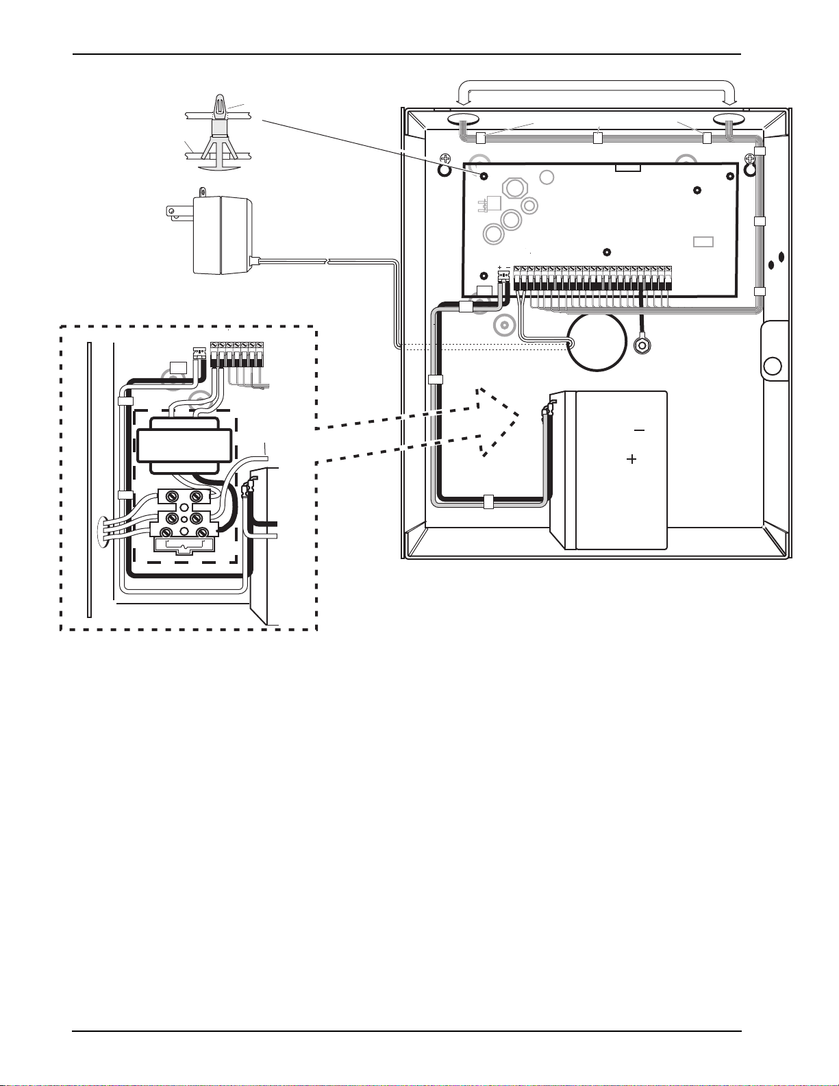
220
1. Inser t Stand off into cabinet
mounting hole in the
desired location. Snap-inplace .
2. P osition circuit board
mounting holes ov er
standoffs . Press fir mly
on board to snap-in-place .
230/240 V 50/60 Hz InternationalAC
PC Boar d
Cabinet
CON1
BA T+BA T-
AC
16.5V /40V A
AC AC
Stand Of f
Pr imar y:120V A C/60Hz.
Secondar y: 16.5VAC 40VA
DSCPTD 1640U
Class II Tr ansf or mer
NO TE: Do not connect
transf or mer to receptacle
controlled by a s witch
To EGND
Te r m inal
Nor th America Onl y
Cab le Tie (not supplied) recommended
220
High V oltage .D isconnect AC Po wer
and telephone lines bef ore servicing
CON1
BA T+BA T-
AU X+ BELL +
AC AC RED BL KY EL GRN Z1 COM Z2 Z3 COM Z4
AU X- BELL-
PO WER LIMITED
UA 50 3
PC1404
W ARNING:
PGM1
PGM2
12V / 4 or 7 AHr
EGND
See ground wiring
diagram on page v
of this manual
BLA CK
RE D
RING TIP
R1 T1
suggested GND point
DSC
FUSE
IMPORTANT:
a)This equipment, Alar m Controller PC1404 shall
be installed and used within an en vironment that pr ov ides th e
pollution degree max 2 and ov er vo ltages categor y II
NON-HAZARDOUS LOCA TIONS , indoor onl y. The equipment is
FIXED and PERMANENTL Y connected and is designed to be
installed by ser vice persons only; [ser vice person is defined as a
person ha ving the appropr iate technical training and e xper ience
necessar y to be aw are of hazards to which that person ma y be
e xposed in per fo rm ing a task and of measures to minimi ze the ri sks
to that person or other persons .]
b)The connection to the mains supply must be made as per the local
author ities ru les and regulations.
An appropr iate disconnect de vice must be pr ov ided as par t of th e
bu ilding installation. Where it is not possi bl e to rely on identification of
the neutral in the AC Mains supply the disconnecting device must
disconnect both poles simultaneously (line and neutral). The device
shall disconnect the supply during servicing.
c)The equipment enclosure must be secured to the bu ilding str uctur e
bef ore operation.
e)Inter nal wi ri ng must be routed in a manner that pr ev ents:
- Excessi ve strain on wire and on te rm inal connections;
- Loosening of te rm inal; connections;
- Damage of conductor insulatio n
f) Disposal of the used batte ri es shall be made according to the w ast e
reco ve ry and recycling regulations applicab le to the intended mar k et.
NON-PO WER LIMITED
W ARNING:
Incorrect connections may result in PTC failure or improper operation.
DSC Model BD7-12
or equiv alent
Inspect wiring and ensure connections are correct be fo re appl ying po we r.
Incorrect connection of batteries ma y result in batter y rupture or Fire Hazar d.
Do NO T allo w metal objects to connect the Positive and Negative Terminals.
Ensure that batteries are connected with correct polarity [Red to (+), Blac k to (-)].
F ailure to compl y with this ma y result in batte ry rupture and/or Fire Hazar d.
All cir cuits are c lassified fo r UL Installations as Po wer Limited/Class II Power Limited
e xcept fo r battery leads which are not po wer limited.
Do NO T r oute an y wiring o ver cir cuit boar ds .M aintain at least 1"(25.4mm) separation.
A minim um of 1/4" (6.4mm) separation mu st be maintained at all points between
po wer limited wiring and all other non-po wer limited wiring.
DG009606
High V oltage . Disconnect AC Po wer
and telephone lines bef ore servicing
W ARNING:
vi

1 Introduction
1 Introduction
This manual provides installation and programming information for the PC1404 four-zone panel security system.
1.1 Compatibility Requirements
The PC1404 product is the central component of the four-zone security system. Interaction with associated system devices is hardwired,
which follows DSC keybus standards. Communications with the central station may be achieved by a hardwired phone line. DLS may
also be remotely connected to the panel via phone line or locally connected via the PC-Link header. Shown below are the supported and
unsupported modules for the PC1404.
Note: All necessary information required to meet UL listing requirements is included in this document.
7DEOH6XSSRUWHG0RGXOHV
Module Current Draw, mA Software Versions
PC1404RKZ Keypad*
PK5500/PK5501/PK5508/PK5516 Keypads*
LCD5511 Fixed Message LCD Keypad*
LED5511 8-Zone LED Keypad*
PC1555RKZ 8-Zone LED Keypad*
PC5200 Power Supply*
PC5204 Power Supply with 4 PGMs*
PC5208 Low Current PGM Module*
PC5601 LED Status Module
TL300 T-Link TL300 IP Alarm Communicator*
GS3060 GPRS Universal Cellular Alarm Communicator*
3G3070 HSPA (3G) Universal Cellular Alarm Communicator*
GS3105/3125-K & BA Wireless Alarm Communicator 250 (excluding outputs) 3.0
*UL/ULC-listed devices.
120 1.0
125 1.0, 1.1, 1.2, 1.3
85 1.0
100 1.0
85 2.0
20 2.0
20 2.0
20 1.0
30 1.0
360 1.2-1.5
120 3.1, 3.2
120 3.5
Note: For UL/ULC-listed installations, use only UL/ULC-listed devices.
Note: For SIA CP-01: 2010 compliant installations, the minimum required components are: PC1404 Control Panel and PC1404RKZ
keypad. Optional components that can be used with the system are: PK55XX series keypad. These keypads can only be used for SIA
CP-01: 2010 Compliant installations if the emergency keys are not enabled.
7DEOH8QVXSSRUWHG0RGXOHV
7DEOH&RPSDWLEOH6PRNH'HWHFWRU0RGHOV
Module 4-Wire Smoke Detectors 2-Wire Smoke Detectors
PC5100 2-wire interface PC5964 Large Audio Station FSA-410x FSA-210x
RFK55XX Keypad PC5401 RS232 Module FSA-410xT FSA-210xT
RF5132-433 Wireless Receiver PC5400 Printer + DVACS FSA-410xS FSA-210xS
RF5108-433 Wireless Receiver
PC5108 Zone Expander TL260 Series Communicators FSA-410xLST FSA-210xLST
PC5320 Zone Expander
PC5950 Audio Module TL250 Communicator FSA-410xRT FSA-210xRT
PC5904 Large Audio Station TL150 Communicator FSA-410xRS FSA-210xRS
PC5921 Audio Station IT100 Integration Module FSA-410xRST FSA-210xRST
PC5961, PC5962 Small Audio
Station
PTK5507 Touchscreen keypad
Escort 5580 Telephone
Interface
GS2060 Series Wireless
Alarm Communicator
IT120 Integration Module FSA-410xLRST FSA-210xLRST
FSA-410xST FSA-210xST
FSA-410xR FSA-210xR
Note:
For model numbers above, x = A (ULC); x = B (UL); x = C (CE)
1.2 Product Specifications
Control and Indicating Equipment Specifications
Features
• Supports zone doubling — supervised and distinguishable
• NC/Single/Double EOL support
1

PC1404
• Supports up to 4 keypads
• 1 Partition support
• 128 events
• Communications: on-board PSTN
• 4 phone numbers
• 2-wire and 4-wire smoke detector support
• Auto-arming
Zone Configuration
• 31 zone types and 11 programmable zone attributes
• Supports up to 4 hardwired NC, SEOL, DEOL zones, expandable to 8 with the zone doubling feature
• Keypad zones allow the system to be configured to support 8
zones—4 onboard zones and up to 4 keypad zones
Access Codes
• Supports 39 user codes and 1 master code
• 6 programmable user code attributes; see PC1404 User Manual for details
• Duress codes derived from user codes ± 1 digit are not allowed
Programmable Outputs (PGMs)
• Up to an additional 12 PGMs are supported with PGM
expander for a total of 14 PGMs on the system
• 24 PGM types
• PGM 1: 50mA switched
• PGM 2: 300mA current-limited switched. This PGM supports
compatible 2-wire smoke detectors (90mA current limited)
Power Supply
• 1.5A regulated
• Panel current draw:
240 VAC Primary............................... 180 mA(AC)(Max.)
120 VAC Primary............................... 330 mA(AC)(Max.)
16.5 VAC Secondary.......................... 1.5A(AC)(Max.)
• Nominal panel current draw: 85mA
• 550mA Auxiliary Supply, 11.1-12.5VDC (12VDC nominal)
• Positive Temperature Coefficient (PTC) for BELL, AUX+
and battery terminals
• Reverse Battery Detection/Protection
• Supervision for loss of AC power and low battery
• Output ripple voltage 85mV p-p (Max.)
Power Requirements
• AC Transformer Requirements:
Primary = 120V
Secondary = 16.5V
AC, 50/60Hz, 0.33A
AC, 40VA (North American market)
DSC PTD1640U (UL); DSC PTC1640 (ULC).
Primary = 230/240V
Secondary = 16.5V
AC, 50/60Hz, 0.21A
AC, 40VA (Australian, South African,
International markets)
• Transformers must be Energy Efficient as per the local rules
and regulations
• High-efficiency transformer for Australia
Battery
• 12V sealed lead acid battery
• Charging mechanism supports 4Ah, 7Ah batteries
• Charging rate: 240mA (12 hrs Max.)
• Range for the charge current: 200mA–350mA
• Backup time: 24 hrs (use 7Ah battery) or 4 hrs (use 4Ah battery)
• Replace battery every 3–5 years.
• Low battery trouble indication threshold 11.25VDC
• Low battery trouble restore threshold 11.75VDC
• Battery deep discharge protection: fixed at 9.6V
Aux+:
• Voltage: 11.1–12.5VDC
• Current: 550mA (Max.)
Note: Aux and PGM outputs share the 550mA load.
Keybus Terminals
• Clock: yellow
• Data: green
Memory
• 32Kbit serial CMOS EEPROM with write protection
• Retains programming and system status on AC or battery failure
• Data retention: 20 years min.
Bell Output
• 12V, 700mA supervised (1k) bell output (current limited at 2A)
• Steady (for burglary), pulsed or temporal three (for Fire),
temporal four (for CO) alarm cadences supported
• Bell short detection
Operating Environmental Conditions
• Temperature range: 0°C to 49°C (32°F-120°F)
• Relative humidity: 85% noncondensing
Telco Terminals
Ring R-1
Tip T-1
• Ring detection: 30V RMS min
• Protection for high ring voltage - Sidactor
PCB Dimensions
• Length: 153 mm (6.0")
• Width: 94 mm (3.7")
• Height (tallest component): 28 mm (1.1")
System Supervision Features
The PC1404 continuously monitors a number of possible trouble
conditions and provides audible and visual indication at the keypad. Trouble conditions include:
• AC Power Failure
• Fire Trouble
• Telephone Line Trouble
• Low Battery Condition
• Bell Circuit Trouble
• General System Trouble (indicates peripheral module trouble)
• General System Tamper (indicates peripheral module tamper)
• Loss of System Time
• Tamper by Zone
• Failure to Communicate
False Alarm Prevention Features
• Audible Exit Delay
• Audible Exit Fault
• Communication Delay
• Entry Delay Urgency
• Quick Exit
• Cross Zone Burglary Alarm
• Rotating Keypress Buffer
Cabinets
Several cabinets are available for the PC1404, as follows:
PC5003C Cabinet
Cabinet for the PC1404 alarm controller. Dimensions (approximate):
288mm x 298mm x 78mm/11.3"x 11.7" x 3"
PC500C Cabinet Household Fire and Burglary
Cabinet for the PC1404 alarm controller. Dimensions (approximate):
213mm x 235mm x 78mm/8.4" x 9.25" x 3.0"
1.3 Out of the Box
Verify that the following components are included in your system:
• one PC500C cabinet
• one PC1404 main control circuit board
• one Installation Manual with programming worksheets
• one PC1404 Quick Reference Guide
• one hardware pack consisting of:
–one 2-wire battery harness; L=34cm black & red
–four 3/8" nylon standoffs; locking PCB support
–eight 5600 (5.6K) 1/2W 5%TR resistors
–eight 1500 (1.5K) 1/2W 5%TR resistors
–four 2400W5%TR resistors
–one 2200W5%TR resistor
–one 1000W5%TR resistor
2

2 Installation
2 Installation
The following sections provide a thorough description of how to
wire and configure devices and zones.
2.1 Installation Steps
Read this section completely before you begin. Once you have
an overall understanding of the installation process, carefully
work through each step.
Step 1: Creating a Layout
Draw a rough sketch of the building to get an idea of where all
alarm detection devices, keypads and other modules are to be
located.
Step 2: Mounting the Panel
Begin the installation by mounting additional modules in the
cabinet using the stand-offs provided. Then, mount the cabinet
in a dry, protected area close to an unswitched AC power source
and the incoming telephone line. Before attaching the cabinet to
the wall, be sure to press the four circuit board mounting studs
into the cabinet from the back. After you have attached the cabinet to the wall, stick the provided DSC logo sticker on the front
of the cabinet.
Note: You must complete all wiring before connecting the battery, telephone wires and/or applying AC to the panel. Before
these operations are performed, the cabinet shall be properly
secured to the building structure.
Note: The metallic cabinet door shall be locked using a key
(lock) and minimum 2 (two) screws.
Step 3: Wiring the Keybus (Section 2.4)
Wire the Keybus to each of the modules following the guidelines provided in Section 2.4 Keybus Operation and Wiring.
Step 4: Zone Wiring (Section 2.8)
You must power down the control panel to complete all zone
wiring. Please refer to Section 2.9 Zone Wiring when connecting zones using normally closed loops, single EOL resistors,
double EOL resistors, Fire zones and Keyswitch Arming zones.
Step 5: Complete Wiring (Section 2.2)
Complete all other wiring including bells or sirens, telephone
line connections, and ground connections following the guidelines provided in Section 2.2 Terminal Descriptions.
Step 6: Powering up the Control Panel
Once all zone and Keybus wiring is complete, power up the control panel. First, connect the red battery lead to the positive terminal and the black lead to negative. Then, connect the AC.
Note: Connect the battery before connecting the AC. You must
apply AC power to the panel for at least 10 seconds, or the panel
will not function. The panel will not power up on the battery
connection alone.
Step 7: Keypad Assignment (Section 2.6)
In order for keypads to be properly supervised, each must be
assigned to a different slot. Please follow the guidelines provided in Section 2.5 Current Ratings – Modules & Accessories
when assigning keypads.
Step 8: Supervision (Section 2.7)
The supervision of each module by the panel is automatically
enabled upon power up. Please verify that all modules appear on
the system according to the instructions in Section 2.6 Keypad
Assignment.
Step 9: Programming the System (Sections 4 & 5)
Section 4 Programming explains how to program the panel. Fill
out the Programming Worksheets completely before attempting
to program the system. (See Section 5 Programming Worksheets).
Step 10: Testing the System
Test the panel thoroughly to ensure that all features and functions are operating as programmed.
2.2 Terminal Descriptions
Battery Connection
A 12V 4 Ah or 7Ah rechargeable battery is used as a backup
source of power in the event of an AC power failure. A sealed,
rechargeable, lead acid or gel type battery is required to meet UL
requirements for power standby times.
Note: UL/ULC Residential Burglary installations require 4 Hrs
power standby time plus 4 minutes alarm annunciation.
Note: UL/ULC Residential Fire installations require 24 Hrs
power standby time plus 4 minutes (UL) or 5 minutes (ULC)
alarm notification.
Standby Battery Guide
Battery Charging Current: 350 mA
Battery Size Standby
4 Hr 24 Hr
4Ahr 550mA --
7Ahr 550mA 180mA
Note: Connect the battery before connecting the AC.
Connect the RED battery lead to the positive battery terminal;
connect the BLACK lead to negative.
Note: Battery capacity will deteriorate with age and number of
charge/discharge cycles. Replace every 3-5 years.
AC Terminals
The panel requires a 16.5VAC, 40VA transformer. Connect the
transformer to an unswitched AC source and connect the transformer to these terminals.
Note: Do not connect the transformer until all other wiring is
complete. The transformer secondary wire distance is as shown
below:
AWG Feet Metres
24 5.8 1.8
22 9.3 2.8
20 14.8 4.5
18 23.5 7.2
Note: For UL installations, use only wire size AWG 18, 20 or 22.
Note: For UL Listed installations, do NOT connect transformer
to a receptacle controlled by a switch.
AUX+ and AUX- Auxiliary Power Terminals
These terminals provide up to 550mA of current at 11.1–12.5
V
DC for modules, powered detectors, relays, and LEDs. If the
total current required exceeds 550mA, an additional power
supply is required (e.g., PC5200, PC5204). Refer to Table 1-1,
6XSSRUWHG 0RGXOHV for the current draw of individual devices.
Connect the positive side of any device requiring power to the
AUX+ terminal, the negative side to AUX- (ground). The AUX
output is protected. This means that if too much current is drawn
from these terminals (such as a wiring short), the panel will
temporarily shut off the output until the problem is corrected.
Bell Output Terminals – BELL+ and BELL-
These terminals provide up to 700 mA of continuous current at
11.1-12.5 V
ing-type equipment (e.g. DSC SD-15 WULF). To comply with
NFPA 72 Temporal Three Pattern requirements: Program Section [013] Option 8 ON.
Note: Steady, pulsed alarms and temporal four (CO) alarms are
also supported.
DC for powering bells, sirens, strobes or other warn-

PC1404
Connect the positive side of any alarm warning device to
BELL+, the negative side to BELL–. Please note that the Bell
output is protected: if too much current is drawn from these terminals (such as a wiring short), the panel will shut down the output. Two amps can be drawn for short periods only.
The Bell output is supervised
and power limited by 2A
PTC. If an alarm warning
device is connected to the bell
terminals, a termination resistor is not necessary. If no
alarm warning devices are in
use, connect a 1000 resistor
across BELL+ and BELL– to prevent a Bell Circuit Trouble
from being generated. For more information, please refer
to[*][2]Trouble Display).
Keybus Terminals – AUX+, AUX-, YEL, GRN
The Keybus is used by the panel to communicate with modules
and vice versa. Each module has four Keybus terminals that
must be connected to the four Keybus terminals on the panel.
For more information, see Section 2.4 Keybus Operation and
Wiring.
Programmable Output Terminals –
PGM 1 and PGM 2
Each PGM output is designed so that when activated by the
panel, the terminal will switch to ground.
PGM 1 can provide up to 50mA. Connect the positive side of the LED or
buzzer to AUX+, the negative side to
PGM 1. PGM 2 can provide up to
300mA current-limited switched programmable output. If more than 50 mA
of current are required, a relay must be
used. Please study PGM wiring in the
accompanying diagram. Two-wire
smoke detectors (90mA current limited) are supported using PGM 2.
For a list, please see the section on
Programmable Output Options.
Note: For UL installations, use only UL-listed relays.
Zone Input Terminals – Z1 to Z4
Each detection device must be connected to a zone on the control panel. It is suggested that one detection device be connected
to each zone; wiring multiple detection devices to a single zone,
however, is possible. For zone wiring specifics, please see Section 2.9 Zone Wiring.
Telephone Line Wiring
Wire the telephone connection terminals (TIP, Ring, T-1, R-1) to
an RJ-31x Connector as indicated. For connection of multiple
devices to the telephone line, wire in the sequence indicated.
Use 26 AWG wire minimum for wiring.
Telephone format is programmed in option [350]. Telephone
Call Directions are programmed in options [351][376].
T-1
R-1
TIP
RING
Please ensure that all plugs and jacks meet the dimension, tolerance and metallic plating requirements of 47 C.F.R. Part 68,
SubPart F. For proper operation, no other telephone equipment
should be connected between the control panel and the telephone company facilities. Do not connect the alarm panel communicator to telephone lines intended for use with a fax
machine. These lines may incorporate a voice filter which disconnects the line if anything other than fax signals are detected,
resulting in incomplete transmissions.
BRN
GRA
GRN
RED
RJ-31X
Ground Connection
Using an insulated green wire of minimum 22AWG, connect the
EGND terminal from the PCB assembly to the GND Point on the
control panel's cabinet. The GND Point could be any available
hole on the back or on the side of the metal cabinet where the
grounding wire from the EGND terminal on the PCB assembly
and the grounding wire from the building electrical installation
could be attached together as indicated in the wiring diagram on
page v or on the wiring diagram attached to the cabinet.
Note: Wire and installation hardware not included.
2.3 Wire Routing for Power & Non-Power
Limited
All wiring entry points are designated by the arrows. All circuits
are classified UL installation power limited except for the battery leads which are not power limited. A minimum ¼” (7mm)
separation must be maintained at all points between power limited and non-power limited wiring and connections.
Note: Wire entry for power limited wiring must be separated by
using a different entry access from non-power limited wiring.
2.4 Keybus Operation and Wiring
The Keybus is used by the panel to communicate with all connected modules and vice versa. The red (AUX+) and black
(AUX-) terminals are used to provide power, while the yellow
(YEL) and green (GRN) terminals are clock and data respectively.
Note: The four Keybus terminals of the panel must be connected
to the four Keybus terminals or wires of all modules.
The following restrictions apply to Keybus wiring:
• Keybus should be run in minimum 22 AWG quad (0.5mm),
maximum 18 AWG; two pair twist is preferred.
• The modules can be home-run to the panel, connected in
series or T-tapped, provided that the maximum wire distance from the control panel to any module does not exceed
1,000' (305m).
• Any module can be connected anywhere along the Keybus.
You do not need to run a separate Keybus wire for keypads
etc.
Note: Depending on a module's current draw, there may be additional limitations of the wire run length of power and ground.
• Shielded wire should not be used.
4

2 Installation
Example of Keybus Wiring
Note: Module (A) is correctly
wired within 1,000'/305m of wire
from the panel.
Module (B) is correctly wired
within 1,000'/305m of wire from
the panel. Module (C) is NOT
wired correctly as it is further
than 1,000'/305m from the panel, in wire distance.
2.5 Current Ratings – Modules & Accessories
In order for the PC1404 system to operate properly, the power
output capabilities of the main control and the expansion devices
must not be exceeded. Use the data presented below to ensure
that no part of the system is overloaded, affecting its function.
PC1404 (12 VDC)
AUX+: 550mA: Subtract the listed rating for each keypad,
expansion module and accessory connected to AUX+ or Keybus.
BELL: 700mA Supervised (1k Ohm) Bell Output (Current Limited at 2A).
Note: AUX and PGM outputs share the 550mA load.
PC1404 Device Ratings (at 12 VDC)
• PC1404RKZ keypad: 120mA
• PK55XX keypad: 125mA
• PC1555RKZ keypad: 85mA
• PC5601 LED status module: 30mA
• LCD5511 keypad: 85mA
• LED5511Z keypad: 100mA
• PC5200 power supply: 20 mA
• PC5204 power supply with 4 PGMs: 20 mA
• PC5208 low current PGM module: 20 mA
• TL300 communicator: 360mA
• GS3060 communicator: 120mA
• 3G3070 communicator: 120mA
• GS3105/3125-K & BA communicator: 250mA
Other Devices
Please read the manufacturer’s literature carefully to determine
the maximum current requirements for each device—during
activation or alarm—and include the proper values for loading
calculations. Connected devices must not exceed system capabilities during any possible operational mode.
2.6 Keypad Assignment
Once the wiring is complete and the keypad is fixed on the wall,
a 2-digit number must be entered to tell the system the partition
and slot assignment of the keypad. At each keypad installed on
the system
1. Enter Installer Programming by pressing [*][8][Installer
Code].
2. Press [000] for keypad programming.
3. Press [0] for Partition and Slot Assignment.
4. Enter a 2-digit number to specify the partition and slot
assignment as follows:
a) As the PC1404 does not have partitions, enter [1] for
the first digit. If the first digit is incorrectly programmed with a value greater than 1, the keypad will
not respond when connected to a single partition system (e.g. PC1404). Press and hold the 1 key on the keypad, then re-enter section [000][0] to correct the
programming.
b) Assign each keypad to its own slot (1 to 8). LED key-
pads, the LCD5511 and the PC1404RKZ keypads are
always assigned to slot 1 by default. PK5500 keypads
are always assigned to slot 8. Keypad assignment is
required, as it tells the panel which slots are occupied.
The panel can then generate a keypad supervision trouble when the keypad is detected as missing.
Note: One LCD keypad must be assigned to slot 8 in order to
upload keypad programming using DLS software.
c) Press the [#] key twice to exit programming.
d) After assigning all keypads, perform a supervisory reset
by entering [*][8][Installer Code][902]. The panel will
reset supervision and re-enroll modules on the system.
How to Program Function Keys
By default, the 5 function keys on each keypad are programmed
as Stay Arm (03), Away Arm (04), Chime (06), Sensor Reset
(14) and Quick Exit (16). You can change the function of each
key on every keypad:
1. Go to the keypad where you want to change the function
key programming and enter Installer Programming.
2. Press [000] for Keypad Programming.
3. Enter [1] to [5] to select a function key to program.
4. Enter the 2-digit number [00] to [32] to select the feature
you want the function key to have. For a complete list, see
Function Key Options on page 19.
5. Continue from step 3 until all function keys are programmed.
6. To exit Installer Programming, press [#] twice.
2.7 Supervision
By default, all modules are supervised upon installation. Supervision is enabled at all times so that the panel can indicate a trouble if a module is removed from the system.
To check which modules are currently connected and supervised, enter programming Section [903] from Installer Programming. An LCD keypad will allow you to scroll through the
display of connected modules. A connected module which does
not show as being present will appear as a trouble condition and
the Trouble light on the keypad will turn ON. This condition
may be due to one or more of the following reasons:
• the module is not connected to the Keybus
• there is a Keybus wiring problem
• the module is more than 1,000'/305m from the panel
• the module does not have enough power
For more information regarding module supervision troubles,
please refer to [*][2]Trouble Display.
2.8 Removing Modules
The panel must be instructed to no longer supervise a module
being removed from the system. To remove the module, disconnect it from the Keybus and reset the supervision field by entering [902] in Installer Programming. The panel will reset
supervision of all existing modules attached to the keybus.
2.9 Zone Wiring
For a complete description of the operation of all zone types,
please refer to [001] Zone Definitions.
There are several different ways in which zones may be wired,
depending on which programming options have been selected.
The panel can be programmed to supervise normally closed, End
of Line, Double End of Line, or zone doubling loops. Please
refer to the following diagrams to study each type of individually supervised zone wiring.
Note: Any zone programmed for Fire, 24-hr Supervisory, or CO
must be wired with a single End of Line (SEOL) resistor regardless of the type of zone wiring supervision selected for the panel
([013] First System Options: [1]-[2]).
Note: If you change the zone supervision options from DEOL to
SEOL or from NC to DEOL (See [013] First System Options,
Options [1] or [2]), you should power down the system completely, and then power it back up. If you do not, the zones may
not work correctly.
PC1404
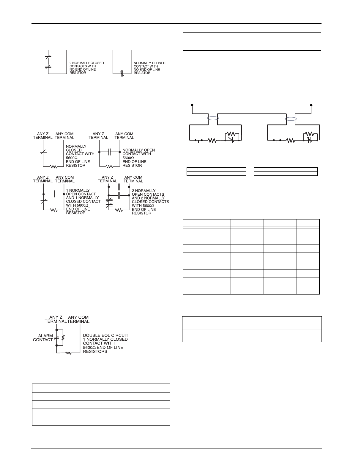
Normally Closed (NC) Loops
ANY Z
TERMINAL
ANY COM
TERMINAL
To enable normally closed loops, Section [013], Option [1] must
be ON.
Note: This option should only be selected if Normally Closed
(NC) detection devices or contacts are being used.
ANY Z
TERMINAL
ANY COM
TERMINAL
Single End Of Line (EOL) Resistors (5600)
To enable panel detection of single end of line resistors, Section
[013], Options [1] and [2] must be OFF.
Note:
This option should be selected if either Normally Closed (NC)
or Normally Open (NO) detection devices or contacts are being
used.
Double End of Line (DEOL) Resistors
Double End of Line resistors allow the panel to determine if the
zone is in alarm, tampered or faulted.
To enable panel detection of double end of line resistors, Section
[013], Option [1] must be OFF and Option [2] must be ON.
Note: If the Double EOL supervision option is enabled, all hardwire zones on the main panel must be wired for Double EOL
resistors, except for Fire, CO and 24-hr Supervisory zones.
Note: Do not use DEOL resistors for Fire zones, CO zones or
24-hr Supervisory zones. Do not wire Fire zones to keypad zone
terminals if the DEOL supervision option is selected.
End of Line Resistors ............................... Section [013]: [1]
Double End of Line Resistors.................. Section [013]: [2]
2.10 Zone Doubling
Zone Doubling is a feature that will allow you to double the
zones on the main board from 4 to 8. To enable zone doubling,
Section 13 Option [7] must be ON. All zones must be wired
according to the following diagram. Only Normally Closed
devices can be used with zone doubling.
Zone input
Wire A Wire B
RZ1
RE1
TAMPER
Zone 1, 2, 3, 4 Zone 5, 6, 7, 8
RE1 RZ1 RE5 RZ5
1500 5600 1500 2400
N.C. N.C.
RE5
TAMPER
Note: All resistors are 5% tolerance.
The loop using the 1500
and 5600resistors is the first zone
(Zone 1, 2, 3, or 4). The loop using the 1500and
resistors is the second zone (Zone 5, 6, 7, or 8). For example,
loop 1 is Zone 1 and loop 2 is Zone 5. The following table shows
zone status under certain conditions:
Nominal Tamper Zone 1 Zone 5 Fault
–––
11000 – open open –
8600 – open restore –
7100 – – –
5400 – restore open –
3900 – – –
3000 – restore restore –
1500 – – –
Note: The following will be seen by the installer if the end-ofline resistors have not been installed correctly, when both zones
are physically closed:
COM
RZ5
2400
Note: This option can only be selected if Normally Closed (NC)
detection devices or contacts are being used.
The following chart shows zone status under certain conditions:
Loop Resistance Loop Status
0 (shorted wire, loop shorted) Fault
5600 (contact closed) Secure
Infinite (broken wire, loop open) Tamper
11200 (contact open) Violated
6
Zone 1 open, Zone 5
restored
Both zones showing
as faulted.
This may be caused by RE1 and RZ1 as
well as RE5 and RZ5 being switched.
This may be caused by RE1 and RZ1, or
RE5 and RZ5, being switched.
Note: If zone doubling is enabled, fire zones should not be programmed. 2-wire smoke loops can still be used.
Note: If zone doubling is enabled, keypad zones should not be
programmed.
Note: If fire zone types are programmed in Section [001], or if a
keypad zone has been assigned, it will not be possible to enable
the zone doubling option in Section [013].

2 Installation
2.11 Fire Zone Wiring
All 4-wire smoke detectors must be wired according to the following diagram:
All 2-wire smoke detectors must be wired according to the following diagram:
2-wire smoke detector initiating circuit:
• Style B (Class B), Supervised, Power Limited
• UL Compatibility Identifier . . . . . . . . . . . . . . . . PC14-1
• DC Output Voltage . . . . . . . . . . . . . . . . . . 9.3-13.7 VDC
• Detector Load . . . . . . . . . . . . . . . . . . . . . . . .2mA (Max.)
• Single-end-of-line (SEOL) resistor. . . . . . . . . . . . 2200
• Loop resistance . . . . . . . . . . . . . . . . . . . . . . .24(Max.)
• Standby impedance . . . . . . . . . . . . . . . . . 1250(Nom.)
• Alarm impedance . . . . . . . . . . . . . . . . . . . .650 (Max.)
• Alarm current . . . . . . . . . . . . . . . . . . . . . . .94mA (Max.)
2.12 CO Detector Wiring
CO DETECTOR
POWER ALARM TROUBLE
NC C NO NC C NO
-
+
PC1404
-
AUX
+
Z
ANY
ZONE
INPUT
ANY
(SEOL TYPE 41)
COM
RM-1/RM-2
POWER LOOP
SUPERVISORY
(12V
RELAY
DC
, 35mA)
-
+
ALARM
INITIATING
LOOP
RESISTANCE
100 ohm
The following CO detector models can be used with PC1404
v1.0 and higher control panels:
• Potter Model CO-12/24, UL File E321434
• Quantum Model 12-24SIR, UL File E186246
• NAPCO Model FW-CO12 or FW-CO1224, UL File
E306780
• System Sensor Model CO1224, UL File E307195
SEOL
RESISTOR
(5600 ohm)
2.13 Keypad Zones
Each “z” keypad on the system has a zone input to which a
device - such as a door contact - can be connected. This eliminates the need to run wires back to the control panel for every
device.
To install the keypad, open the keypad plastic at the bottom of
the unit. Locate the five terminals on the keypad circuit board.
Connect the four Keybus wires from the control panel: the red
wire to R, the black to B, the yellow to Y and the green to G.
To connect the zone, run one wire to the Z terminal and the other
to B. For powered devices, use red and black to supply power to
the device. Run the red wire to the R (positive) terminal and the
black wire to the B (negative) terminal.
When using end of line supervision, connect the zone according
to one of the configurations outlined in Section 2.9 Zone Wiring.
End of line resistors must be placed on the device end of the
loop, not at the keypad.
Note: Only non 24-hr burglary zones can be configured as keypad zones for UL Listed products.
Assigning Keypad Zones
When using keypad zone inputs, each input used must be
assigned a zone number in Installer Programming.
1. Ensure that you have enrolled all installed keypads into the
desired slots. (See Section 2.6 Keypad Assignment.)
2. Enter [*][8] [Installer Code] to go to Installer Programming.
3. Enter Section [20] for Keypad Programming. There are
eight programming locations in this section, one for each
keypad slot.
4. Enter a 2-digit number (01-08) to specify which zone number should be assigned to the keypad slot. This number
must be entered in the location corresponding to the keypad
to which each zone is connected.
5. Press [#] twice to exit Installer Programming.
Example: The zone on an PK5500 keypad in Slot 8 is to be
assigned Zone 3. In Section [020], scroll to Option [8] and enter
(03).
Note: Keypad Zones 1-4 will replace Zone terminals Z1-Z4 on
the control panel.
Note: Once the keypad zones are assigned, you must also program zone definitions and zone attributes. (See also 5.2 Programming Worksheets).
Note: Keypad zones can only be used for household burglaryinitiated devices. Do not place the device more than 3 feet from
the keypad. The keypad zone must be tested weekly.
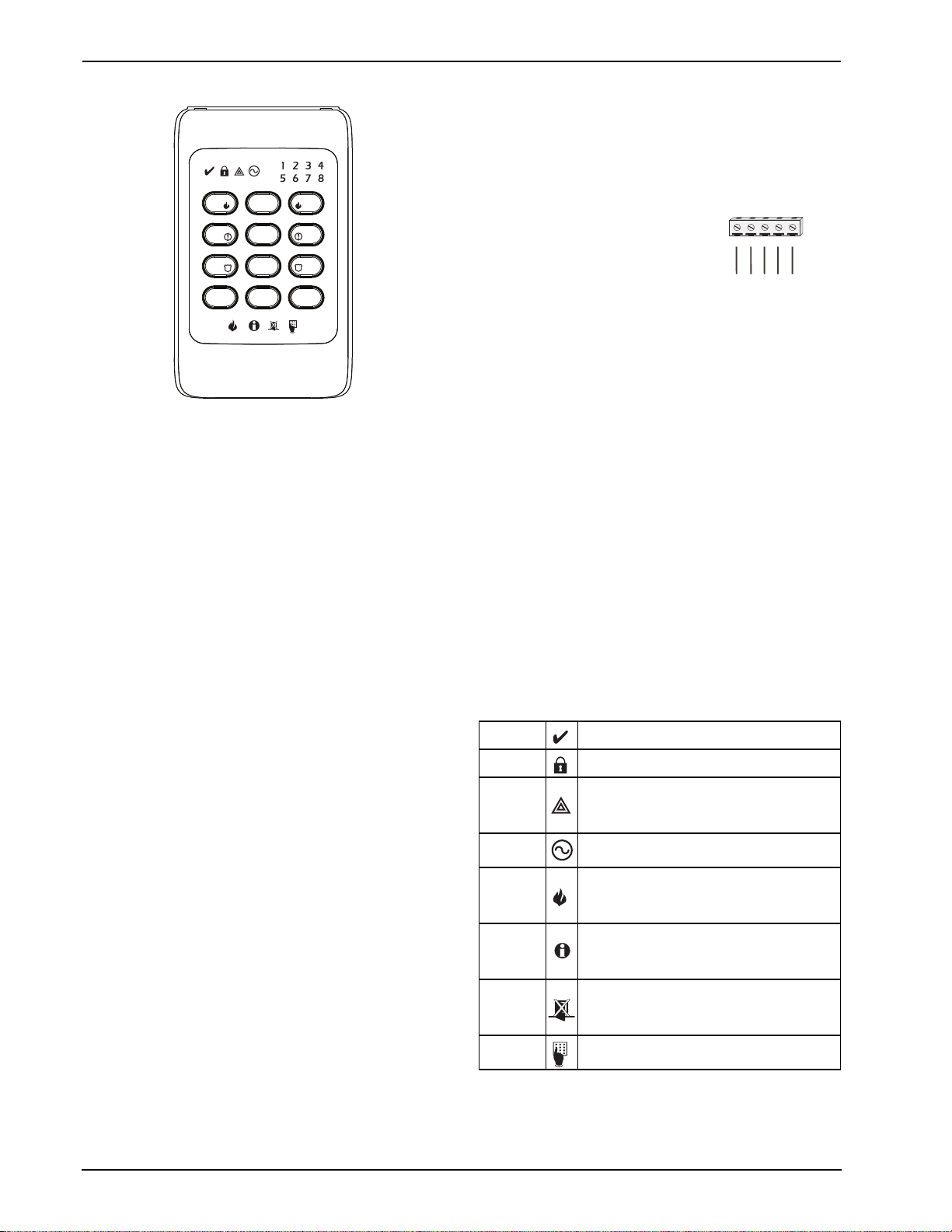
PC1404
2.14 PC1404RKZ Installation Instructions
3
2
1
6
5
4
9
8
7
#
0
*
The PC1404RKZ is compatible with the PC1404 security system. These instructions shall be used in conjunction with the
Installation Manual of the PC1404 alarm controller.
The PC1404RKZ keypad presents system status using LEDs
along with symbols and numbers. The keypad can be used on
security systems with up to 8 zones.
Specifications
• Supply voltage: 7VDC-14.5VDC
• Compatible control panel keybus connection provided by
DSC
• Connects to control panel via 4-wire keybus
• One keypad zone input
• Current draw: 120mA (maximum)
• Optional tamper version
• Four programmable function keys
• Ready (green), Armed (red), and Trouble (amber) status
lights
Note: This keypad is available to order with white (WH) or
yellow (YEL) LED backlights.
Unpacking
The PC1404RKZ package includes the following parts:
•one PC1404RKZ keypad •one tamper switch
• three mounting screws •one set of Installation Instructions
• three anchors for •keypad inner door labels
wall-mounting screws
• one end-of-line resistor
Mounting
Mount the keypad where it is accessible to designated points of
entry and exit. Once a dry and secure location is selected, perform the following steps to mount the keypad:
1. Remove the keypad frontplate by inserting a screwdriver
into the slots located on the top of the keypad.
2. Secure the keypad backplate to the wall in the desired location. Use all the screws provided. Use the plastic anchors
supplied if the unit is to be mounted on drywall.
3. To use the keypad tamper, insert the supplied tamper
switch into the opening located in the centre of the backplate, and secure the tamper to the wall with a screw.
4. For tamper use, the backplate should be mounted on a
smooth, flat surface. If mounting on a rough surface, fasten
the enclosed surface tape to the wall to even out the surface
area where the tamper will be positioned.
5. Before attaching the keypad to its backplate, complete the
keypad wiring as described in the next section.
Wiring
1. Before wiring the unit, ensure that all power (AC transformer and battery) is disconnected from the control panel.
2. Connect the four Keybus wires from the control panel (red,
black, yellow and green) to the keypad terminals (RED,
BLK, YEL, GRN). Consult the diagram below:
3. Connect a device, such as a door contact, to the ‘Z’ terminal of the
PC1404RKZ
PC1404RKZ. This eliminates the
need to run wires back to the control
GRN ZYELBLKRED
panel for the device. To connect the
zone, run one wire from the device to
RED
GRNYELBLK
To Zone Input
the ‘Z’ terminal and the other wire
from the device to the BLK (black) terminal. For powered
devices, run the red wire to the RED (positive) terminal and
the black wire to the BLK (negative) terminal. When using
end of line supervision, connect the zone according to one
of the configurations outlined in your system’s Installation
Manual.
Applying Power
Once all wiring is complete, apply power to the control panel:
1. Connect the battery leads to the battery.
2. Connect the AC transformer.
For more information on control panel power specifications, see
the control panel Installation Manual.
Note: Do not connect the power until all wiring is complete.
Enrolling the Keypad
See 2.6 Keypad Assignment to enroll the keypad.
Power Save Mode
If power save mode is enabled and AC power fails, all keypad
lights, including backlighting, shut off. The keypad lights will
come back ON after a keypress, entry delay, audible alarm or
keypad buzzer condition (except door chime). The keypad lights
will return to the off state after 30 seconds of no activity. If the
AC fail condition is restored, the keypad lights will be
reactivated.
Keypad Icons
Ready Status
Armed Status
Trouble
Status
AC Status
Fire Memory
Alarm
Memory
Bypass
Programming
The green ready status icon is on when the system is
ready to arm.
The red armed status icon is on when the system has
been successfully armed.
The trouble status icon is lit when there is a trouble
present on the system. To see if a trouble is present
press [*][2]. If any number is lit, a trouble condition is
present. Refer to your system manual to identify what
trouble condition is present.
The green AC status icon can be configured to indicate
presence or absence of AC; see AC LED Options and
Keypad Toggle Options sections [5] and [6].
The red fire memory icon is lit when a fire alarm is in
progress or has occurred. If zone 4, as an example, is
programmed as a fire zone and goes into alarm, the
keypad will turn on the zone 4 LED and the fire icon to
indicate a fire alarm is present on zone 4.
The alarm memory icon is lit when there is a zone in
alarm memory. To see if there is a zone in alarm
memory press [*][3]. If any number is lit, the
corresponding zone is in alarm memory. Refer to your
system manual for further information.
The bypass icon is lit when a zone is bypassed on the
system. To see if a zone is bypassed press [*][1]. If any
number is lit, the corresponding zone is bypassed. Refer
to your system manual for information on bypassing and
removing a bypass.
The programming icon indicates when the keypad is in
Installer Programming. This LED also activates when
the keypad is busy.
Changing the Buzzer Level
The user can change the keypad buzzer frequency by pressing
and holding the [*] key. After the key has been pressed for 2 seconds, the keypad changes the frequency and beeps so the user
8

2 Installation
can hear the new tone. If the key is held down, every second the
keypad will increment the frequency and sound another tone.
There are 21 levels. Once the desired level is reached, press [*]
to exit.
Programming the Function Keys
The function keys are programed in sections [000][1-4]. By
default, the 4 function keys on the keypad are programmed as
Stay Arm (03), Away Arm (04), Chime (06), and Sensor Reset
(14). Activate the function keys as follows:
Function key 1 - Press and hold the #2 key for 2 seconds
Function key 2 - Press and hold the #5 key for 2 seconds
Function key 3 - Press and hold the #8 key for 2 seconds
Function key 4 - Press and hold the #0 key for 2 seconds
See Keypad Function Keys below for the other function key
options available for your system.
Emergency Key Options (Fire, Auxiliary, Panic)
You can enable or disable the Fire, Auxiliary and Panic keys at
each keypad. These keys are enabled by default. To turn any of
the emergency keys on or off on the keypad:
1. Enter [*][8][Installer Code].
2. Enter [000] to go to keypad programming.
3. Enter section [6].
4. To turn the emergency key options on or off, press [1], [2],
or [3]:
[1] ON=Fire key enabled OFF=Fire key disabled
[2] ON=Auxiliary key enabled OFF=Auxiliary key disabled
[3] ON=Panic key enabled OFF=Panic key disabled
5. When complete, press [#] to exit.
Activating Emergency Keys
• Fire Key
To activate a fire alarm, press and hold keys #1 and #3 simultaneously for 2 seconds.
• Auxiliary Key
To activate an auxiliary alarm, press and hold keys #4 and #6
simultaneously for 2 seconds.
• Police Key
To activate a police alarm, press and hold keys #7 & #9 simultaneously for 2 seconds.
Night Light Feature (available in PC1404RKZWH order
code)
White LEDs are on the left and right side of the keypad to make
the keypad easier to locate in the dark. To turn the night lights on
or off:
1. Enter [*][8][Installer Code].
2. Enter [000] to go to keypad programming.
3. Enter Keypad Toggle Options section [6].
4. Turn option 4 on or off to enable or disable the night light
feature.
5. When complete, press [#] to exit.
AC LED Options
The AC LED can be enabled or disabled, and can be configured
to indicate if AC is present or absent. To turn the AC LED on or
off:
1. Enter [*][8][Installer Code].
2. Enter [000] to go to keypad programming.
3. Enter Keypad Toggle Options section [6].
4. To turn the AC LED feature on or off, press 5.
5. To control whether the LED indicates AC present or absent,
press 6.
6. When complete, press [#] to exit.
Backlighting Intensity Adjustment
The keypad has 5 backlighting intensity settings. To adjust the
backlighting intensity:
1. Enter [*][8][Installer Code].
2. Enter [000] to go to keypad programming.
3. To adjust the intensity of the backlighting LEDs, repeatedly
press [9].
4. When complete, press [#] to exit.
Programming worksheet
[000] Keypad Programming
1.Enter [*][8][Installer Code].
2.Enter [000] to go to keypad programming.
[0] Keypad Enrollment
Valid entries are 01-18; e.g., enter [11] for partition 1, slot 1.
1st digit: Enter 0 to 8 for partition assignment (0 = Global Keypad).
2nd digit: Enter 1 to 8 for slot assignment
Default:
[1]-[4] Function Key Assignments
Defaults
Keypad Function Keys
[00] - Null key (key not used) [13] - Command output 1 (*71)
[01]-[02] - Not used
[03] - Stay arm [15] - Not used
[04] - Away arm [16] - [*][0] Quick exit
[05] - [*][9] No entry arm [17] - [*][1] Activate stay/away
[06] - [*][4] Chime On/Off [18] - Not used
[07] - Not used [19] - Command output 3 (*73)
[08] - [*]1]Bypass mode [20] - Night arming
[09] - [*]2] Trouble display [21] - Command output 4 (*74)
[10] - Not used [22]-[24] Not used
[11] - [*][5] User code programming [25] - Instant stay arm
[12] - [*][6] User functions [26]-[32]- Not used
[6] Keypad Toggle Options
Option
11
I_________I________|
[1] Key 1 [2] Key 2 [3] Key 3 [4] Key 4
03 04 06 14
Stay Away Chime
I_________I________| I_________I________| I_________I________| I_________I________|
1 [F] key enabled/disabled
2 [A] key enabled/disabled
3 [P] key enabled/disabled
4 Night light enabled/disabled: When enabled, the
white LEDs on each side of the keypad are activated. When disabled, the white LEDS on each
side of the keypad are deactivated.
5 AC LED enabled/disabled: When enabled, the
keypad’s AC LED indicates either the presence or
absence of AC power to the control panel,
depending on the programming of option 6 in section [000][6]. When disabled, the keypad’s AC
LED remains off in all conditions.
6 AC LED on when AC present/AC LED on when
AC absent: This toggle option requires option 5 in
section [000][6], AC LED enabled/disabled, to be
enabled. When this option is on, the keypad’s AC
LED turns on to indicate that the control panel has
AC power, and turns off to indicate that AC power
has been lost. When this option is off, the keypad’s AC LED turns on to indicate that AC power
has been lost, and turns off to indicate that the
control panel has AC power.
7-8 Not used
Sensor
Reset
[14] - Command output 2 (*72)/
Sensor reset

PC1404
3 Keypad Commands
Use any compatible keypad to enter commands and/or program the PC1404 security system. The LED keypad uses function and zone
indicator lights to represent alarm functions and status. The LCD keypad provides a written description on the liquid crystal display and
uses function indicator lights to communicate alarm status to the user.
The PC1404 User Manual provides basic directions for arming and disarming the system, bypassing zones and performing user functions from the keypads. The following sections provide additional details on these functions.
3.1 Arming and Disarming
For a description of basic arming and disarming, please see the PC1404 User Manual. For other methods of arming, please refer to
[*][0] – Quick Arm and [*][9][User Code] – No-Entry Arming.
The event buffer will log “armed in stay mode,” “armed in away mode,” or “armed in night mode” whenever the system is armed.
The arming procedure initiated by pressing Away function key on keypad is the same as the arming procedure initiated by entering user
codes. For CP-01 systems, if there is no exit event (delay 1 zone violated and restored) prior to the exit delay expiring, the system will
be armed in Stay mode.
In an attempt to prevent false alarms, the Audible Exit Fault will notify the user of an improper exit when they arm their system. If a
non force-arming Delay 1 or Delay 2 type zone is left open at the end of the exit delay, the entry delay will begin immediately and the
bell or siren will sound a steady alarm for the entry delay period. At the end of the entry delay period, if the system has not been disarmed it will go into alarm. This feature can be turned OFF in Section [013], Option [6].
3.2 Auto Bypass – Stay Arming
Stay arming allows the user to arm the system without leaving the premises. All zones programmed as stay/away will be bypassed when
the user stay arms the system, so that the user does not have to bypass interior zones manually. (See “Zone Programming” in PC1404
Programming Descriptions. For these descriptions, see the Technical Library section of
When the system is armed using a valid access code, if any zones on the system have been programmed as stay/away zones, the Bypass
light will turn ON. The panel will then monitor all zones programmed as Delay 1 and Delay 2 zones, such as designated entry/exit
doors. If a delay zone is not violated by the end of the exit delay, the panel will bypass all stay/away zones. The Bypass light will remain
on to inform the user that the interior zones have been automatically bypassed by the panel. If a delay zone is violated during the exit
delay, the system will arm in Away mode and all stay/away zones will be active after the exit delay expires.
The user can arm the stay/away zones at any time by entering the [*][1] keypad command. (See “[*][1] Bypassing and Activating Stay/
Away and Night Zones”.)
Stay arming can also be initiated by pressing and holding the Stay function key for two seconds on the supported keypads, if programmed by the installer. For more information regarding Stay arming, see [000] in Keypad Function Programming in PC1404 Programming Descriptions.
3.3 Automatic Arming
The system can be programmed to arm at the same time each day. Upon entry of this section, enter 4 digits for the 24 Hour Auto-Arm
time. At the selected Auto-Arm time, the keypad buzzers will sound for the time programmed in Section [199] to warn that an AutoArm is in progress. The bell can also be programmed to squawk once every 10 seconds during this warning period. When the warning
period is complete, the system will arm with no exit delay and in the Away Mode. Note: For CP-01 systems, the system will arm with
an exit delay. If no Delay 1 zone violation and restore occurs during this exit delay, the system will arm in Away mode. If a Delay 1
zone is left violated when the exit delay ends, an audible exit fault will occur if the feature is enabled. The exit delay restart feature
applies to this entry delay (see Section [18] Option 7.)
Auto-Arming can be cancelled or postponed only by entering a valid access code during the programmed warning period. When the
code has been entered, the warning will be silenced and Auto-Arming will be cancelled or postponed, depending on the programming
of Section [175]. Auto-Arming will be attempted at the same time the next day. Whenever the Auto-Arming process is canceled or postponed, the Auto-Arm Cancellation Reporting Code will be transmitted (if programmed).
If arming is inhibited by one of the following, the Auto-Arm Cancellation transmission will be communicated.
- AC / DC Inhibit Arm
- Latching System Tampers
- Zone Expander Supervisory Fault
Note: PC1404 only supports one entry of Auto-Arm Time programming, so the programmed time shall be used for every day.
3.4 Night Arming
Night arming is intended to arm the perimeter and restrict movement to designated areas in the interior (e.g., hallways from bedrooms
to bathrooms).
If night zones are programmed, entering [*][1] while the system is armed in stay mode will activate all interior zones except those programmed as night zones. The panel can also be armed in Night mode by pressing the Night Arm function key for 2 seconds while the
system is disarmed. The Ready light must be on (disarmed) or the system must be armed in Stay mode to Night arm the system. In
Night mode only night zones (Zone definition 37) are bypassed. When activated, no acknowledgement beeps are sounded, the exit
delay is silent and the panel logs “Armed in Night Mode.” If no night zone types are programmed, the system arms in Away mode and
the panel logs “Armed in Away Mode.”
3.5 [*] Commands
The [*] key commands provide an easy way for the user to access basic system programming – such as programming access codes or
bypassing zones. The user can also use the [*] key commands to check on the system’s status, including viewing trouble conditions and
displaying the event buffer on the LCD keypad.
The [*] key commands can be performed from both LCD and LED keypads. The LED keypad uses the zone indicator lights to display
command information. The LCD display provides written information, guiding the user through each command. The commands in this
section are explained as viewed from an LED keypad. When using an LCD keypad, use the arrow keys (< >) to scroll through information provided. Otherwise, the functions remain the same for both keypad types.
http://www.dsc.com.)
10
 Loading...