

DSC PowerSeries Neo TL8803GI-EU Installation Manual
TL8803GI-EU Dual Path Controller
WARNING: This manual contains information on limitations regarding product use and function and
information on the limitations as to liability of the manufacturer. The entire manual should be carefully
read.

Table of Contents
Warning: Installer Please Read Carefully 3
Alarm.com introduction 5
IP/HSPA 3G module - TL8803GI-EU 5
Contact information 6
Features 6
Communicator ratings 6
Communicator compatibility 7
Installation 8
Tools and supplies required 8
Mounting Instructions 8
Step 1: Enable module 9
Step 2: Connect the TL8803GI-EU 9
1: Connect data bus 10
2: Connect power 11
3:Connect the PC-Link cable 11
4: Connect Ethernet (optional) 11
5: Connect external antenna (optional) 11
6: Power up 12
Step 3: Verify installer code to activate Alarm.com module 12
Step 4: Perform dual-path test (module registration) 12
Step 5: Allow module to auto-program 12
Enroll Alarm.com Image Sensor 13
Panel settings 13
Central station and telephone line settings 13
Troubleshooting 16
Module status information 16
Troubleshooting LEDs 16
LED functions 17
LED details 17
LED L1 (red) 17
LED L2 (yellow) 18
LED L3 (yellow) 18
LED L4 (green) 18
LED L5 (yellow) 19
Various module states (modes) 19
Improving wireless signal strength 19
Walking the customer through new user setup on the web 20
Interactive Service Menu 21
Interactive menus 21
Installer programming 21
User functions 21
Limited Warranty 23
End User License Agreement 23
Regulatory Information 25
- 2 -

Warning: Installer Please Read Carefully
Note to installers
The warnings on thispage c ontain vital information. As the only individual in contact with system use rs, it is the installer’s re sponsibility to
bring eac h item in this warning to the attention of all use rs of this system.
System failures
This system has been ca refully designed to be as effective as possible.
There are circ umstance s, however, involving fire, burglar y, or other
types of emergencies where it may not provide protec tion. Any alarm
system of any type may be compromised deliber ately or ma y fail to
opera te as expe cted for a variety of reasons. Some, but not all, of the
rea sons may be:
Access by intruders
Intruders may enter through a n unprotected access point, circumvent a
sensing device, evade de tection by moving through an are a of insufficient cove ra ge, disconnect a warning device, or interfere with or prevent the proper operation of the system.
Component failure
Although e ver y effort has been made to make this system as re liable as
possible, the system may fa il to func tion as intended due to the failure
of a component.
Compromise of radio frequency (Wireless)
A device 's signals may not reach the re ceiver under all circumstances,
which could include: metal objects placed on or near the radio path,
delibera te jamming or other inadver tent radio signal interfe rence.
Criminalknowledge
This system conta ins se curity features which we re known to be effe ctive at the time of manufac ture. It is possible for persons with c riminal
intent to deve lop techniques which reduce the ef fectiveness of these
fea tures. It is important that your security system be re viewe d periodically to e nsure that its features remain ef fective and that it is
updated or replac ed if it is found that it doe s not pr ovide the protec tion
expected.
Failureof replaceable batteries
This system’s wireless transmitters have been designed to provide severa l year s of battery life under normal conditions. The expected battery life is a function of the de vice e nvironment, usage, a nd type.
Ambient conditions such a s high humidity, high or low temperature s, or
large tempera ture fluctuations ma y reduc e the expecte d battery life.
While ea ch transmitting device ha s a low battery monitor which identifies when the batteries need to be r eplac ed, this monitor may fail to
opera te as expe cted. Regular testing and maintenanc e will keep the system in good oper ating condition.
Inadequate installation
A secur ity system must be installed properly in orde r to provide
adequate protection. Every installation should be e valuated by a secur ity professional to ensure that all a cc ess points a nd are as ar e cove re d.
Locks and latches on windows and doors must be secure and opera te
as intended. Windows, doors, wa lls, c eilings and other building mate rials must be of sufficient strength and construc tion to provide the le vel
of protec tion e xpec ted. A reevaluation mustbe done during a nd afte r
any construc tion a ctivity. An evaluation by the fire and/or police depa rtment is highly rec ommended if this se rvice is ava ilable.
Inadequate testing
Most problems that would pr eve nt an alarm system f rom opera ting as
intended ca n be found by regula r testing and maintenanc e. The c omplete system should be tested weekly and immediately after a break-in,
an attempted bre ak- in, a fire, a storm, an earthquake, an accident, or
any kind of construction activity inside or outside the premises. The testing should include all sensing de vices, keypads, consoles, alarm indicating devices, and any other operational devices that are part of the
system.
Insufficient time
There may be circumstance s when the system will ope rate as intended,
yet the occupants will not be protec ted from an emerge ncy due to their
inability to respond to the warnings in a timely manner. If the system is
remotely monitored, the response may not occur in time to protect the
occupants or their belongings.
Motion detectors
Motion detectors can only detect motion within the designated areas as
shown in their respective installation instruc tions. The y cannot discriminate between intruders and intended occupants. Motion detec tors
do not provide volumetric area protection. They have multiple beams
of detec tion and motion ca n only be detecte d in unobstruc ted areas
covered by these beams. They ca nnot detect motion which occurs
behind walls, ceilings, floors, closed doors, glass partitions, glass doors
or windows. Any type of tampering whether intentional or unintentional
such as masking, painting, or spraying of any material on the lenses,
mirrors, windows or any other pa rt of the detection system will impair
its prope r operation. Passive infrar ed motion de tectors operate by sensing c hange s in tempera ture. However their effec tiveness ca n be
reduc ed whe n the ambient tempera ture rises near or above body tempera ture or if ther e are intentional or unintentional sources of heat in or
near the detec tion a re a. Some of these heat source s could be heaters,
radiators, stoves, barbec ues, fireplac es, sunlight, stea m vents, lighting
and so on.
Powerfailure
Control units, intrusion detectors, smoke detectors and many other
secur ity de vices require a n adequate powe r supply for proper operation. If a device oper ates from batteries, it is possible for the batteries
to f ail. Even if the batteries have not failed, they must be charged, in
good condition and installed c orrectly. If a device oper ates only by AC
power, any interruption, howeve r brief, will render that device inopera tive while it doe s not ha ve powe r. Power interruptions of any length
are often accompanied by voltage fluctuations which may damage electronic equipment such as a security system. After a power interruption
has occurre d, immediately conduct a complete system test to ensure
that the system ope rates as intended.
Security and insurance
Regardless of its ca pabilities, an alarm system is not a substitute for
proper ty or life insurance . An alar m system also is not a substitute for
proper ty owners, re nters, or other occupants to ac t prudently to prevent
or minimize the harmful eff ec ts of an emergency situation.
Smokedetectors
Smoke de tectors that are a part of this system may not properly alert
occupants of a fire f or a number of reasons, some of which follow.
The smoke detectors may have been improperly installed or positioned.
Smoke may not be able to reac h the smoke detec tors, such as when the
fire is in a chimney, walls or roofs, or on the other side of c losed doors.
Smoke de tectors may not de tect smoke from fires on another level of
the residence or building. Every fire is different in the a mount of
smoke produce d and the rate of burning. Smoke de tectors cannot sense
all types of fires equa lly well. Smoke dete ctors may not provide timely
warning of fires ca used by carele ssness or safe ty haza rds such as
smoking in bed, violent explosions, e scaping ga s, improper storage of
flammable materials, overloaded electrical circ uits, c hildren playing
with matches, or arson. Even if the smoke detector operates as intended, there may be circumstances whe n there is insufficient warning to
allow all occupa nts to escape in time to avoid injury or de ath.
- 3 -

Telephone lines
If telephone lines are use d to transmit a larms, they may be out of service or busy for c ertain periods of time. Also a n intruder may cut the
telephone line or defeat its operation by more sophisticated means
which may be difficult to detect.
Warning devices
Warning devices such as sirens, bells, horns, or strobes may not warn
people or wa ken someone sleeping if there is an interve ning wall or
door. If wa rning device s are located on a diffe re nt level of the residence or premise, then it is less likely tha t the occupants will be a lerted
or awa kene d. Audible warning devices may be interfer ed with by
other noise sources such as stere os, radios, televisions, air conditioners,
other applianc es, or passing tra ffic. Audible warning devices, howe ver
loud, may not be heard by a hearing-impaired person.
- 4 -

IMPORTANT
This installation manual shall be used in conjunction with the control panel installation manual available online
from the DSC website at www.dsc.com. All the safety instructions specified within that manual shall be
observed. The control panel is referenced as the “panel” throughout this document. This installation guide
provides the basic wiring, programming and troubleshooting information.
The alarm communicator is a fixed, wall-mounted unit, and shall be installed in the location specified in these
instructions. The alarm communicator module should NOT be installed inside of the metal alarm panel casing;
doing so will significantly impair cellular and RF (Z-Wave) transmissions. The equipment enclosure must be
fully assembled and closed, with all the necessary screws/tabs, and secured to a wall before operation. Internal
wiring must be routed in a manner that prevents:
l Excessive strain on wire and on terminal connections,
l Interference between power limited and non power limited wiring,
l Loosening of terminal connections, or
l Damage of conductor insulation.
WARNING: Never install this equipment during a lightning storm.
Safety information
The installer must instruct the system user on each of the following:
l Do not attempt to service this product. Opening or removing covers may expose the user to dangerous
voltages or other risks.
l Any servicing shall be referred to service persons only.
l Use authorized accessories only with this equipment.
l Do not stay close to the equipment during device operation.
l Do not touch the external antenna.
Alarm.com introduction
The purpose of this guide is to provide installation and operating instructions for the Alarm.com communicator
module. The following sections offer you a brief overview of its capabilities. Some capabilities and features
vary based on the Alarm.com service plan selected. Visit www.alarm.com/Dealer or contact Alarm.com for
more information.
Note: The Dual Path IP/HSPA 3G module is available in the model TL8803GI-EU.
Note: Image sensor functionality may not be enabled in all regions.
The module TL8803GI-EU contains the IP/Radio subassembly and the PC-Link to RS422 conversion interface.
The module is compatible only with NEO Alarm Control Unit models HS2128, HS2064, HS2032 and HS2016
software versions 1.1 and above.
IP/HSPA 3G module - TL8803GI-EU
The Dual Path module enables wireless reporting of all alarms and other system events from the DSC Neo control panel using an all-digital, HSPA wireless (cellular) network or an Ethernet network. The module can be
used as the primary communication path for all alarm signaling, or as a backup to a telephone connection to the
central monitoring station. The wireless alarm signaling and routing service is operated by Alarm.com. The
HSPA module also features integrated support for Alarm.com’s home automation solution with built-in
Z-Wave capabilities.
Note: Alarm.com’s home automation solution with built-in Z-Wave capabilities is not EN501311:2006/A1:2009 and EN50136-1:2012 evaluated.
- 5 -

Contact information
For additional information and support on Alarm.com modules, initial account setup, home automation, and all
other Alarm.com products and services, please visit: www.Alarm.com/dealer or contact Alarm.com technical
support at: 1-866-834-0470.
Features
l 128-bit AES encryption using cellular and Internet
l Back-up or primary cellular alarm communication and Ethernet port
l Automatically switches to 2G (EDGE/GPRS) if HSPA (3G) service is not available
l Full event reporting to central station
l Cellular periodic test transmission
l Integrated call routing
l Panel remote uploading/downloading support using cellular or Internet
l PC-LINK connection
l Programmable labels
l SIA and Contact ID (CID) formats supported
l Signal strength and trouble display LEDs
l Subscriber Identity Module (SIM) card included with communicator
l Supervision heartbeats sent using cellular
l 2-way audio capable when used with audio module HSM2955(R). - Refer to HSM2955(R) manual
Communicator ratings
Model TL8803GI-EU
Power supply ratings
Input Voltage
Current consumption
Standby Current (Average Value) 100 mA @12 V (I)
Alarm (Transmitting) Current (Peak Value) 200 mA @ 12V (I)
Cellular Network HSPA 3G
Operating Frequency QuadBand GSM/GPRS/EDGE + HSPA in 850/900/2100 MHz
Environmental specifications
Operating Temperature -10°C to 55°C
Storage Temperature -34°C to 60°C
Humidity 93%RH non-condensing
Mechanical specifications
Dimensions 6" x 8.9" x 1.3"
Weight 365 g (I)
11.3 V - 12.5 V DC
(providedby DSC NEO compatible control panel)
- 6 -

Communicator compatibility
Communicator
TL8803GI-EU
Receiver/
Panel
Receiver
Panel
Description
l Sur-Gard System I-IP Receiver, version 1.13+
l Sur-Gard System II Receiver, version 2.10+
l Sur-Gard SG-DRL3-IP, version 2.30+ (for Sur-Gard System II I Receiver)
l Sur-Gard SG-DRL4-IP version 1.20+(for Sur-Gard System IV Receiver)
l Sur-Gard SG-DRL5-IP version 1.00+(for Sur-Gard System 5 Receiver)
l HS2016, version 1.1+
l HS2032, version 1.1+
l HS2064, version 1.1+
l HS2128, version 1.1+
Note: Enter [*][8][Installer Code][900][000] at keypad to view the panel version number.
Products or components of products, which perform communications functions only complies with the requirements applicable to communications equipment as specified in EN60950-1, Information Technology Equipment
- Safety - Part 1: General Requirements. Such components include, but are not limited to: hubs; routers; NIDs;
third-party communications service providers; DSL modems; and cable modems.
- 7 -
Installation
INSTALLATION
Follow these guidelines during installation:
l Before affixing the communicator to a wall, verify the HSPA signal level at the installation location. On a
keypad, press and hold the 5 key for 2 seconds to view the HSPA signal level. An installation location
with a sustained signal level of two or more bars is recommended.
l Do not exceed the total output power of the panel when using panel power for the TL8803GI-EU module,
hardwired sensors, and / or sirens. Refer to the specific panel installation instructions for details. Only one
module can be used per panel.
l To minimize potential interference with cellular signaling, avoid mounting the communicator in areas with
excessive metal or electrical wiring, such as furnaces or utility rooms.
Do not mount the TL8803GI-EU communicator inside of the metal alarm panel enclosure.
Tools and supplies required
You need the following tools and supplies:
l Small flat-head and Phillips screwdrivers
l Screws (included)
l Antenna (included)
l 16 pin ribbon cable (included)
Mounting Instructions
Before fixing the equipment to the wall, verify the HSPA signal level available at the installation location is
strong.
Mount the TL8803GI-EU in a dry, secure, non-hazardous location.
To wall mount:
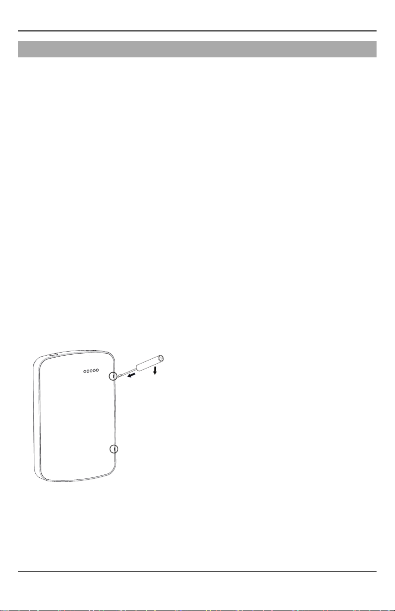
1. Insert a flathead screwdriver into the slots and pry up to remove the front cover.
Figure 1 - Removing the front cover
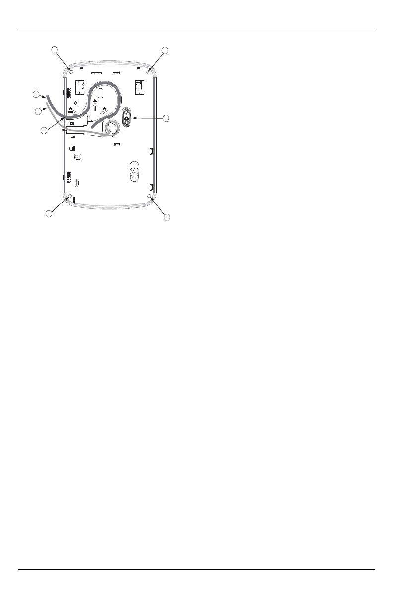
2. For surface-run wires, remove the two breakaway tabs at the side of the backplate.
3. Route the RS422 and Ethernet cables through the retaining clips as shown in figure 2. Run the wires in the
direction indicated by the arrows.
Note: For information on control panel power specifications, refer to the control panel installation
manual.
Caution: Route all the wiring according to local codes and regulations.
- 8 -
A
A
A
A
C
E
D
B
Figure 2 - TL8803GI-EUbackplate
TL880
A: Mounting holes
B. Wall tamper plate
C: Breakaway tabs
D: RS422 cable
E: Ethernet cable
Installation
4. Secure the backplate to the wall using the four mounting holes. (See figure 2)
Note: Use all four screws provided. Use the plastic anchors if mounting on drywall. If using the tamper,
secure the tamper plate to the wall with a screw.
Step 1: Enable module
For the Alarm.com module to communicate with the panel, section [382] option 5 at the panel must be set to
ON. This section is OFF by default and must be enabled for the system to function properly. This must be done
before connecting the PC-Link cable to power up the module to ensure all initialization commands are processed properly.
Step 2: Connect the TL8803GI-EU
Caution: Ensure that the alarm panel is fully powered down (i.e., AC and battery disconnected) prior to connecting the TL8803GI-EU.
- 9 -
Installation
HS2016/2032/2064/2128
PCLINK_2
Alarm Controller Cabinet
HSPA Controller
A
B
D
C
PCL-422
Mounted in Alarm Controller Cabinet
HSPA Controller Board
RX-
RX+
TX+
TX-
+12V
GND
+12V
GND
E
F
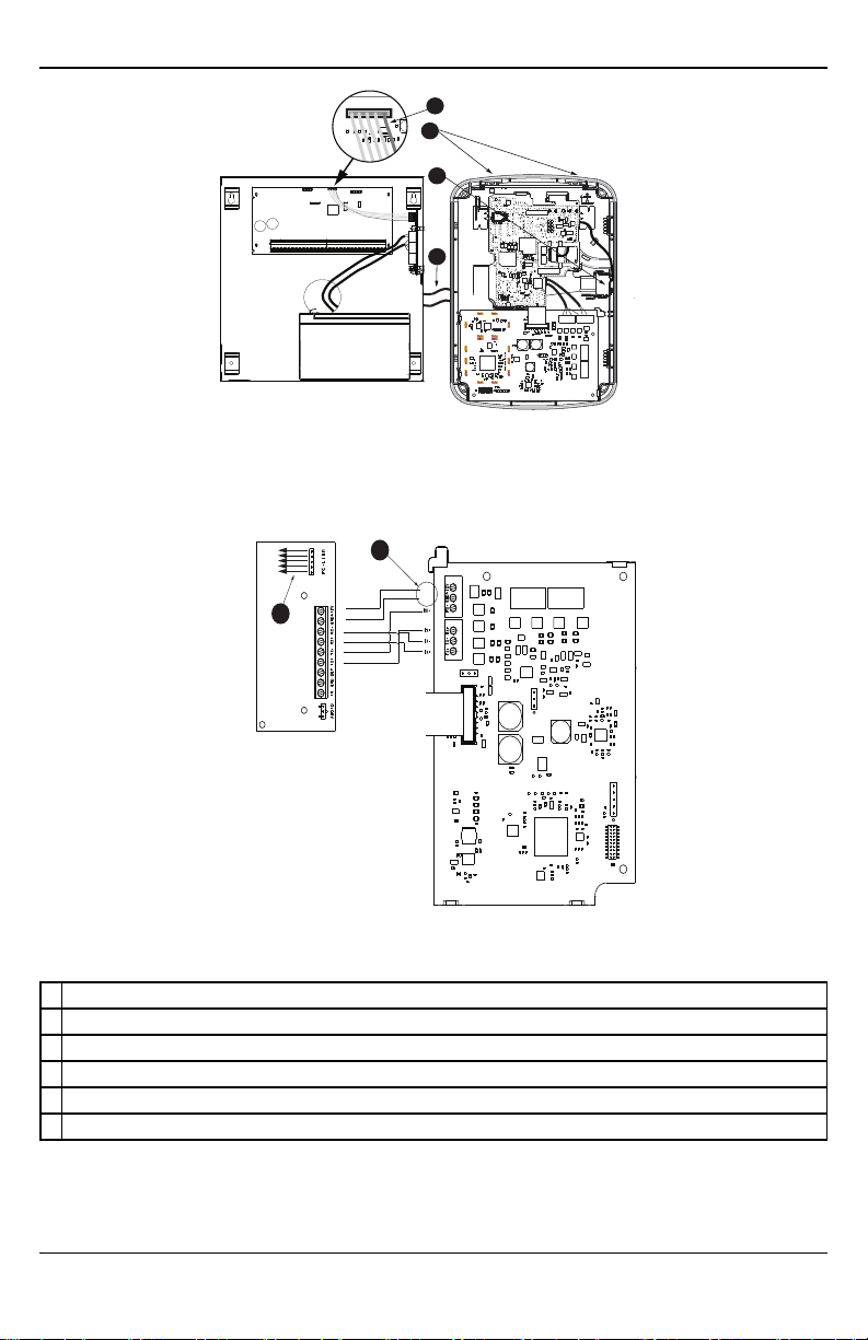
Figure 3 - HSPA controller and alarm controller cabinet
Figure 4 - HSPAcontroller board and alarm controller cabinet
A Red wire on alarm controller PCLink2 Header
B Antennaaccess ports
C Ethernet cable connection
D Quad cables (100' / 30m maximum)
E Red wire on PCL-422PCLink Header
F HSPA Controller Board power terminals. Can be connected to power supply module (HSM2204/2300).
1: Connect data bus
The maximum cable length permitted for the data bus is 100ft/30m.
- 10 -

Installation
l Connect the RX+ terminal on the TL8803GI-EU to the TX+ terminal on the PCL-422
l Connect the RX- terminal on the TL8803GI-EU to the TX- terminal on the PCL-422
l Connect the TX- terminal on the TL8803GI-EU to the RX- terminal on the PCL-422
l Connect the TX+ terminal on the TL8803GI-EU to the RX+ terminal on the PCL-422
2: Connect power
The maximum cable length permitted for the power connection is 100ft/30m.
l Connect the GND terminal on the TL8803GI-EU to the GND terminal on the PCL-422
l Connect the +12V terminal on the TL8803GI-EU to the +12V terminal on the PCL-422
3:Connect the PC-Link cable
Note: To ensure correct orientation, refer to items A and D in the wiring diagrams for the proper position of
the red wire on the PC-link cable.
l Connect one end of the supplied PC-Link cable to the PC-Link header on the PCL-422
l Connect the other end of the PC-Link cable to the PC-LINK_2 header on the alarm panel
4: Connect Ethernet (optional)
Note: Refer to item C in the wiring diagram for the correct placement of the Ethernet cable.
A Category 5 (CAT 5) Ethernet cable must be run from a source with Internet connectivity to the communicator module, inside the TL8803GI-EU. The communicator end of the cable must be terminated with an
RJ45 plug.
l Connect one end of the Ethernet cable to the Ethernet port on the communicator
l Connect the other end of the Ethernet cable to the Ethernet port on the router and verify that the link
status LED is on.
All requirements for installation of CAT5 Ethernet cable must be observed for correct operation of the
commmunicator, including but not limited to the following requirements:
l Do NOT strip off cable sheathing more than required for proper termination.
l Do NOT kink or knot the cable.
l Do NOT crush the cable with cable ties.
l Do NOT untwist CAT5 pairs more than 1/2 inch (1.2 centimeters).
l Do NOT splice the cable.
l Do NOT bend the cable at right angles or make any other sharp bends.
Notes:
l CAT5 specification requires that any cable bend must have a minimum 2 inches (5 centimeters) bend
radius. The maximum lenght of CAT5 cable is 328 feet (100 meters).
l Before leaving the premises, the Ethernet communication lines must first be connected to an approved
(acceptable to local authorities) type NID. All wiring must be performed according to the local electrical
codes.
5: Connect external antenna (optional)
Upgraded antennas are available for the TL8803GI-EU if there is inadequate cellular reception at the preferred mounting location. Contact DSC technical support for antenna options.
The TL8803GI-EU has two covered access ports on the top of the enclosure. Remove the plastic tab covering
the desired port and either mount the antenna on the enclosure or use the opening to pass through the antenna
cable.
- 11 -

Installation
Note: Due to the curvature of the enclosure, the plastic port covers are NOT interchangeable. Ensure that any
unused ports are covered with their original plastic tab.
Warning: The external antenna must be installed in a manner to prevent end users from accessing any conductive part of the anntena or antenna cable (i.e., recessed mounting or equivalent).
6: Power up
Connect panel battery and AC power. Once powered, view key items on the LCD. Ensure that the module is
fully connected to the alarm panel using quad cable as shown in wiring diagram.
Step 3: Verify installer code to activate Alarm.com module
Alarms and other signals are not sent to Alarm.com until the installer code is verified. To activate the account,
perform the following steps:
1. Connect the Alarm.com module to the panel. Ensure [382] option 5 is ON.
2. Press [*][8] to enter Installer Programming.
3. Enter the installer code.
4. Press [#] to exit Installer Programming.
To remotely activate a system that is already signaling, complete the following steps:
1. Go to www.alarm.com/dealer.
2. Go to the customer's account.
3. Select the error message at the top of the page.
4. Enter the installer code.
Step 4: Perform dual-path test (module registration)
To initiate module communication with Alarm.com and the cellular network for the first time, perform a
“Dual-Path phone test”. Note that the test can also be used at any time by the installer to force communication
with Alarm.com. To test the cellular path, press and hold [3] for two seconds. To test the broadband path,
press and hold [4] for two seconds. A Dual-Path test can also be completed through the Interactive Services
menu. To perform the Dual-Path test, press [*][6] followed by the master code and [04].
The panel indicates when the test has completed by activating the siren output on medium volume for 2 seconds
followed by full volume for 2 seconds. However, if the test was initiated via the [3] or [4] key, or through the
Interactive Services menu, the siren does not sound. All display lights and LCD pixels turn on. This indicates
that Alarm.com has received and acknowledged the signal. This does not guarantee that the signal went
through to a central station; it confirms that Alarm.com’s Network Operations Center received the signal. The
central station should be contacted directly to verify that the signal was received on the correct account and
that the central station routing settings have been set up correctly. If the signal does not go through to the central station, the panel displays a “Failure to Communicate” message. Double check the account’s central station
Forwarding Settings on Alarm.com and contact technical support if the trouble persists.
Step 5: Allow module to auto-program
After a successful dual-path test, wait 2 minutes for the module to automatically program and initialize before
entering the Installer Programming menus. Entering Installer Programming during module initialization will
cancel the process. LCD keypads display a message indicating when auto-programming is occurring and when
it has completed. During the auto-programming session, the module automatically programs panel settings
required for proper functionality with Alarm.com as noted in the “Panel Settings” section.
- 12 -

Installation
Enroll Alarm.com Image Sensor
Note: This feature can be enabled or disabled on the product. Check with your installer if this feature is activated in your application.
Alarm.com's Image Sensor built-in capability is not UL evaluated.
1. Ensure batteries are removed from the sensor.
2. On the panel, enter the Interactive Services menu. Interactive Services can be accessed, using section
[851] of Installer Programming.
3. Press [*][8] [Installer Code] [851].
4. Scroll to Image Sensor Setup and press [*].
5. Scroll to Learn Image Sensor and press [*]. The keypad displays “Power up or reset I.S. now.”
6. Insert the batteries into the sensor. Wait approximately 20 seconds for the control panel screen to display:
“I.S. [x] Added as Sensor [y].” The LED on the sensor turns solid for 5 seconds once the sensor has
enrolled.
7. Perform another panel comm-test to ensure that Alarm.com receives the updated device equipment list.
This speeds up the sensor initialization process.
l The zone is configured as a virtual zone and programmed automatically into the next available slot in
section [560][001]-[032] starting at zone 126 and counting down for each additional Image Sensor added.
l Once enrolled, the Image Sensor will appear as a normal zone.
l By default, the Image Sensor is enrolled as an Interior Stay/Away zone in zone type 005. Zone type and
attributes can be assigned in the installer menu, in a similar way as regular zones. For more information,
refer to the "Zone Setup" section of the PowerSeries Neo Alarm Controller Reference Manual.
Panel settings
Central station and telephone line settings
Central station and telephone line settings are automatically configured through the CS Forwarding Settings
page of the Alarm.com Dealer Site. The following are the panel settings that are configured through the
Dealer Site page (when required) and must not be configured in the panel:
Section Option Description
015 7 Telephone line monitoring
300 [001] -- PanelCommunication Path - Receiver 1
300 [002] -- PanelCommunication Path - Receiver 2
300 [003] -- PanelCommunication Path - Receiver 3
300 [004] -- PanelCommunication Path - Receiver 4
301 [001] -- Communication telephonenumber 1
301 [002] -- Communication telephonenumber 2
301 [003] -- Communication telephonenumber 3
301 [004] -- Communication telephonenumber 4
309 [001] -- System Call Direction - Maintenance
309 [002] -- System Call Direction - Test Transmission
310 [000] -- System account number
310 [001] -- Partition 1 account number
310 [002] -- Partition 2 account number
310 [003] -- Partition 3 account number
310 [004] -- Partition 4 account number
- 13 -

Installation
Section Option Description
310 [005] -- Partition 5 account number
310 [006] -- Partition 6 account number
310 [007] -- Partition 7 account number
310 [008] -- Partition 8 account number
311 [001] -- Partition 1 Call Direction - Alarm/Restore
311 [002] -- Partition 1 Call Direction - Tamper/Restore
311 [003] -- Partition 1 Call Direction - Opening/Closing
312 [001] -- Partition 2 Call Direction - Alarm/Restore
312 [002] -- Partition 2 Call Direction - Tamper/Restore
312 [003] -- Partition 2 Call Direction - Opening/Closing
313 [001] -- Partition 3 Call Direction - Alarm/Restore
313 [002] -- Partition 3 Call Direction - Tamper/Restore
313 [003] -- Partition 3 Call Direction - Opening/Closing
314 [001] -- Partition 4 Call Direction - Alarm/Restore
314 [002] -- Partition 4 Call Direction - Tamper/Restore
314 [003] -- Partition 4 Call Direction - Opening/Closing
315 [001] -- Partition 5 Call Direction - Alarm/Restore
315 [002] -- Partition 5 Call Direction - Tamper/Restore
315 [003] -- Partition 5 Call Direction - Opening/Closing
316 [001] -- Partition 6 Call Direction - Alarm/Restore
316 [002] -- Partition 6 Call Direction - Tamper/Restore
316 [003] -- Partition 6 Call Direction - Opening/Closing
317 [001] -- Partition 7 Call Direction - Alarm/Restore
317 [002] -- Partition 7 Call Direction - Tamper/Restore
317 [003] -- Partition 7 Call Direction - Opening/Closing
318 [001] -- Partition 8 Call Direction - Alarm/Restore
318 [002] -- Partition 8 Call Direction - Tamper/Restore
318 [003] -- Partition 8 Call Direction - Opening/Closing
350 [001] -- Receiver 1 communicator format
350 [002] -- Receiver 2 communicator format
384 2 Communicator backup options
Notifications
The following panel settings may alter the behavior of customer notifications:
Section Option Description
015 4
If this option is ON, keyfob arming notifications are not associated with a specific
user.
Panel settings changed automatically
Some panel settings are changed automatically when the module is connected to the control panel. These settings must not be altered. They are:
- 14 -

Section Option Value Description
015 6 OFF
017 6 OFF
019 6
024 5 OFF
377
377
377
380 1 ON
380 2 OFF
380 5 OFF
382 6 OFF
804 [sensor #] 003 Five minute delay [07]
Swinger Shutdown
(Maintenance)
AC Failure
Communication Delay
Wireless Device Low
Battery Transmission
Delay
Set according to
dealer's Alarm.com
setting
010
Random value between
001 and 030
001
Master code is not changeable and must be
OFF to ensure the modulecommunicates the
correct master code.
Daylights saving time must bedisabled to
ensure panel time is accurate.
Enables Duress Code changes from
Alarm.com.
Realtime clock must be disabled to ensure
paneltime is accurate.
Swinger Shutdown for maintenance signals
should be set to 010 to ensuretrouble
notifications can be sent.
AC Failure Communication Delay shouldbe
set between 001and 030 to ensure
notifications for power failures are received.
Wireless Device Low Battery Transmission
Delay should be set to 001 to ensure
notifications for low batteries are received.
Communications must be enabledfor the
module to communicate with the panel.
System shouldtransmit alarm restores
immediately when the zone is restored.
The redundant communications method must
be set as backup.
AC Failure Transmission Delay must be in
minutes.
High Traffic Shutdown must be set to five
minutes for devices being used with
Alarm.com's Act ivity Monitoring.
Note: This feature can reduce the battery life
of wireless PIR sensors. In orderto avoid t his,
hardwiredPIR sensors can be used instead.
Installation
Clock
The TL8803GI-EU module sets the panel clock when it connects to Alarm.com and then updates it every 18
hours. It is important to select the correct panel time zone on the Alarm.com website, or the panel time will
not be accurate. If a system is powered up before the customer account has been created, the time zone will
default to Eastern Standard Time.
- 15 -

Troubleshooting
TROUBLESHOOTING
Module status information
Module status information for verifying and troubleshooting the module connection status or errors can be
found through the Interactive Services menus. To access these, press [*][8][Installer Code][851]. See the following table for potential module states.
Status Description
Idle Most common state. Module is not actively sendingdata and no errors are present.
Roaming Roaming on partner network.
SIM Missing The SIM card is missing.
PowerSave
Mode
Registering... The moduleis trying to register on the HSPA network.
Connection
Error
Radio Error
Server Error Identifies a server error. If it persists, the account may have been set up incorrectly.
Connected Currently connected andtransmitting information to the Alarm.com servers.
Connecting... In the process of connecting to Alarm.com.
Updating... Updating signal level.
In addition, some of the information can be retrieved using long key presses from the keypad. Press and hold
the following panel keys for 2 seconds to display the given information on the panel display. Most messages are
displayed for less than 30 seconds but can be cut short by pressing the 0 Key for 2 seconds.
Status
keys
1 key 10-digit module serial numberneededto create the Alarm.com customer account.
2 key Modulefirmware version (e.g., 181a).
3 key
4 key Initiate communication test over the broadband path.
5 key
6 key
7 key Use only when instructed by Alarm.com Technical Support.
8 key
AC power is down.
The moduleis registered on the HSPA network but cannot connect with Alarm.com. Contact
Alarm.com technical support for more information.
Radio portion of the moduleis not operatingcorrectly. Power cycle the panel and call Alarm.com
technical support if the trouble persists.
Description
Initiate communication test over the cellular path.
Important: This test is required to correctly complete the installation.
Wireless signal strength level and module status or error, if any. The panel displays the signal level in bars
(0 to 5) and as a numerical value (0 to 31) followed by the connection mode.
Battery voltage as readby the module, to two decimal places, and the AC power status. (e.g., Battery:
6.79v, AC Power OK).
HSPA frequency used by the module: "High" = 900MHz, 2100MHz; "Low" = 850MHz. The panelspecifies
either “3G” or “2G” depending on your coverage, but always attempt to goto 3G coverage.
Troubleshooting LEDs
Status LEDs indicate network and module status. The following figure shows the location of the status LEDs
on the TL8803GI module.
- 16 -
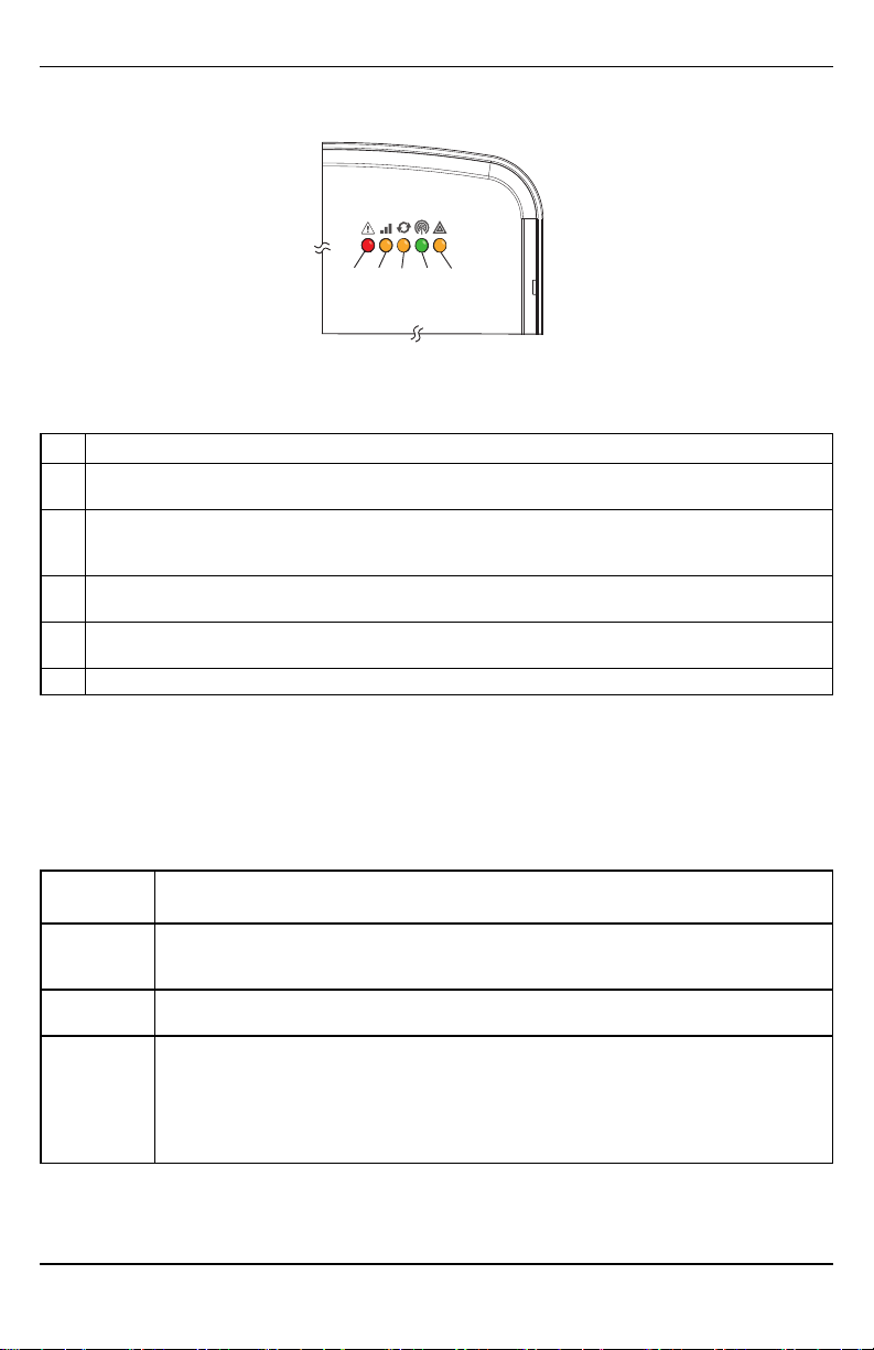
Status LEDs
L1 L2 L3 L4 L5
LED functions
LED Function
General & Cellular ErrorLED. Flashes 1 to 8 times in an 8-second interval to indicate specific error. See section
1
“LED L1 (red)” for errors andcommon fixes.
Broadband Errors & Panel Communication. Flashes 2 to 8 times in an 8-second interval to indicate a specific
2
error on the broadbandpath. Also flashes once every time the modulecommunicates with the panel. See
section “LED L2 (yellow)” for errors and common fixes.
Cellular Communication. Flashes every time the cellular signal level is checked andwhen packets are
3
exchanged with Alarm.com
Cellular Signal Strength Level. Flashes 0 to 5 times to indicate signal strength or toggles on/off slowly when
4
communicating with Alarm.com servers
5 Z-Wave Status & Error LED. See section “LED L5(yellow)” for patterns.
Troubleshooting
LED details
LED L1 (red)
L1 flashes when there is a general error or an error on the cellular path. The number of flashes indicates the
error number. If there are two or more errors at the same time, the errors will flash one after the other. The
LED will stay off for at least four seconds between errors.
Number of
flashes
1
2
3
Module cannot communicate with the panel. Ensure section [382] option [5] is ON. Verify panel
software is version 1.1 or higher. Check the connectors (between the panel andcommunicator) and
powercycle the panel. If the error persists, there can be an issue with the module or panel.
The SIM card is missing. The SIM card holdercan be foundon the module. Verify that the SIM card
holderis closed securely and that there is a SIM card in the holder.
The moduleis trying to register on the HSPA network. If it persists for more than a few minutes, the
module is having problems registering with the HSPA network. Check L4 for signal level. If signal
level is lowerthan 2 “bars”, changethe panel’s location or use a remote antennaoption. If the signal
is good, the module can be roaming on a HSPA network that does not partner with our HSPA
providers, or the SIM card was not activated yet because the Alarm.com account was not created
correctly.
Error and solution
- 17 -

Troubleshooting
Number of
flashes
The moduleis registered on the HSPA network but cannot connect with Alarm.com. Power down the
module, wait one minute, restore power and perform a communications test. Verify signal strength
4
and try a different location for the module/antenna. If the problem persists, contact Alarm.com
Technical Support.
Radio portion of the moduleis not working correctly. If this persists for more than a few minutes the
5
module may need to bereplaced. This erroris extremely rare so verify that the module is flashing 5
times.
This is an error only if it persists for more than a minute. Otherwise, it is just an indication that the
6
module is fixing an unusual condition regardingcommunication with the HSPA network.
7 The moduleis not compatible with this paneltype. Please insert a compatible module.
If it persists, the account may have been set up incorrectly. Contact Alarm.com Technical Support.
8
You will be asked to check the serial number of the module.
Error and solution
LED L2 (yellow)
LED L2 indicates an error on the Broadband path and also flashes with every communication between the module and the panel when there is no error condition present. Normal pattern calls for a series of quick flashes
every two seconds in Idle mode or four seconds in PowerSave mode.
Number of
flashes
Flashes for each communication with the panel, except when LED is displaying a broadband error.
1
This is normal behavior.
The modulecannot establish a connection with the router. Verify the physical connection/wiring to
2
the router. Verify MAC filtering is disabledon the router or add the module’s MAC to the allowed list
of MACs on the router. Verify that DHCP is enabledon the router.
The modulecannot establish a connection with the internet. Verify other devices on the same
3
network can connect, that the panel has AC power, and that there are no special firewall or network
management settings runningon the router.
4 The modulecannot establish communication with Alarm.com. Contact Alarm.com Tech Support.
The Alarm.com backend cannot reach module due to an error with the local firewall blocking signals
6
from reaching the module.
Error and solution
LED L3 (yellow)
L3 flashes with every communication between the module and its radio unit in Idle mode, and with every communication with Alarm.com in Connected mode. In PowerSave mode, this LED flashes in unison with LED 2.
LED L4 (green)
L4 indicates the HSPA signal level as a number of flashes (0 to 5 bars). The number of bars may not correspond to the bars shown on your cell phone. A level of 5 bars is obtained only in the strongest signal conditions.
Signal level is updated every ten seconds if it fluctuates, or every 30 seconds if it is fairly stable. If L4 is not
flashing it indicates one of the following states:
l The module is in PowerSave mode
l The module just powered up
l There is no HSPA coverage in the area. Alarm.com recommends a steady signal level of 2 or higher for
proper operation of the module
Note: In Connected Mode, the LED toggles on and off.
- 18 -

LED L5 (yellow)
LED L5 indicates Z-Wave state and errors. See the table below for more information.
Number of flashes Device status or error
1 Successfully added/removed node (last 60 seconds)
2 Delete Mode
3 Add node attempt failed(last 60 seconds) because device already in network
4 Add Mode
5 Replicate Mode
6 Learn Mode Error(lasts 60 seconds)
7 No Node Info
8 No other nodes are in the network
Various module states (modes)
There are four module states, or modes, as described in the following table:
Mode Description
AC power is correct and the moduleis not currently talking to Alarm.com.
L1 - Flashes general or cellular errors, if any
Idle
PowerSave
Connected
Sleep
L2 – Flashes broadband errors, if any; Communication with panel
L3 - Communication with radiounit
L4 - Signal level (0 to 5 bars)
L5 - Flashes Z-Wave state or errors, if any
The modulejust powered up, AC power is down, or AC power is recently restored and the battery is
recharging. The module is fully functional and goes into Connected mode as soon as a signal needs to be
sent. Press and holdthe 5 Key for 2 seconds to switch the moduleinto Idle mode and update the signal
level reading. The system goes into Idle mode every 2 hours to check for any incoming messages.
L1 - Inactive
L2 - Communication with panel
L3 - Same flashing pattern as L2
L4 - Inactive
L5 - Inactive
The moduleis currently talking to Alarm.com. The module stays in Connected mode for at least four
minutes after reporting an event to Alarm.com, unless the 5 Key is pressed and held for 10 seconds,
which causes the module to go back to Idle mode.
L1 - Flashes general or cellular errors, if any
L2 - Flashes broadband errors, if any; Communication with panel
L3 - Communication with Alarm.com
L4 - Alternates two seconds on, and then two seconds off
L5 - Flashes Z-Wave state or errors, if any
The panel is not connected to AC power, or there is anAC power failure, and the battery level is low. The
module connects to Alarm.com to send a signal, but otherwise draws almost no power.
Troubleshooting
Note: If the TL8803GI module is powered down for a short period of time, buffered messages from Alarm.com can be received when module power is restored.
Improving wireless signal strength
As you make changes to the module location to improve signal strength, request updated signal readings to
verify changes. To request an updated reading, press and hold the “5” key for 2 seconds. In the image below,
the radio has 3 out of 5 bars or 13/31 and is connected to the network.
- 19 -

Troubleshooting
Radio: 123__ 13
Connected
Guidelines for optimal wireless signal strength:
l Install the module above ground level, as high up as possible within the structure.
l Install the module near or adjacent to an exterior-facing wall of the structure.
l Do not install the module inside a metal structure or close to large metal objects or ducts.
l Upgrade the antenna. Contact DSC technical support for antenna options.
Walking the customer through new user setup on the web
This section describes how to help your customer set up their website account, and only applies to customers on
an interactive service plan with an online account. (Skip this step for customers using the module for wireless
signaling only).
Before the customer can configure their website account, the Alarm.com account for that customer must be
created on the Dealer Site, and the HSPA module associated with the account must be installed successfully.
To log in and access their account, the customer can go to www.alarm.com (or custom dealer website address)
to complete the new subscriber setup procedure.
The customer needs the following:
l The web site login and temporary password included on the Alarm.com Welcome Letter, which is
generated when the account was created by the dealer
l A list of their system sensors with corresponding zone IDs
l At least one phone number and e-mail address where notifications can be sent
Note: At least one sensor must be learned into the panel to complete the new subscriber setup. If not all
sensors and touch screens were learned in before powering up the module, an updated sensor list must be
requested by performing a HSPA phone test or requesting an updated equipment list from the Dealer Site.
- 20 -

Interactive Service Menu
INTERACTIVE SERVICE MENU
Interactive menus
The “Interactive Services” menu can be used to access information about the TL8803GI module, install or
remove Z-Wave devices and configure or troubleshoot other interactive features.
The menu times out after 20 minutes. Refer to the following tables for the menu options.
Installer programming
Press [*][8][Installer Code][851] to enter Interactive Services menu.
Menu Description
--Alarm.com Module Status Scroll down throughthe various Alarm.com module information screens.
---Radio Signallevel, connection status, roaming status, and errors (if any)
---HSPA Freq. HSPA frequency used by the module.
---SN Module serial number. Neededto create or troubleshoot an Alarm.com account.
---SIM Card
---Version
---Advanced- Network Use only when instructed by Alarm.com Technical Support.
--Z-Wave Setup
--Number of Z-Wave
Devices
1
2
SIM card number. Sometimes needed to troubleshoot an account. Not applicable to
CDMA radios.
TL8803GI module firmware version and sub-version. Example: 181a; 181 = module
firmware version, a =subversion.
This menu is used to add, remove, and troubleshoot Z-Wave devices and
networks. To control Z-Wave devices via the Alarm.com website and smart phone
apps, you also need to enable Z-Wave services on the account.
The total numberof Z-Wave devices currently known to the module.
Press [*] to enter Z-Wave Add Mode. Make sure the device being added is powered
--AddZ-Wave Device
---Remove Z-Wave Device
---Z-Wave Home ID
---ExtendedRange Option Press [*] to enable/disable extended range
---Communications Test Press [*] to perform ADC communication test
1
up and within 3 to 6 feet of the panel. Refer to the manufacturer’s instructions for
button presses required to enroll devices.
Press [*] to remove an existing Z-Wave device, or to “reset” a Z-Wave device that
1
was previously learned into a different Z-Wave network. Previously enrolled
devices must be reset before they can beenrolledinto the module.
1
Press [*] to query the Z-Wave network Home ID. If the ID is 0, verify that the
module has communicated with Alarm.com and that the Alarm.com account is set
up for Z-Wave.
User functions
Press [*][6][Master Code] to enter User Functions menu. Then scroll to Interactive Services.
Menu Description
--Alarm.com Module Status See Installer Programming section
---Radio See Installer Programming section
---HSPA Freq. See Installer Programming section
- 21 -

Interactive Service Menu
Menu Description
--SN See Installer Programming section
---SIM card See Installer Programming section
---Version See Installer Programming section
---Advanced- Network See Installer Programming section
--Z-Wave Setup
---Number of Z-Wave Devices1See Installer Programming section
---AddZ-Wave Device
---Remove Z-Wave Device1See Installer Programming section
---Z-Wave Home ID
--Communication Test See Installer Programming section
1
Refer to the Home Automation installation instructions and guides on the Alarm.com Dealer Site for more
1
1
1
See Installer Programming section
See Installer Programming section
See Installer Programming section
information on Z-Wave enrollment and troubleshooting.
- 22 -

Limited Warranty
Digital Sec urity Controls wa rrants the original purchaser that for a
period of twelve months fr om the date of purc hase, the product shall be
fre e of defec ts in materials and workmanship under normal use. During the warranty period, Digital Security Controls shall, at its option,
repa ir or replace any defe ctive produc t upon return of the produc t to
its fa ctory, at no c harge for labour and materials. Any replacement
and/or re paire d parts are warra nted for the remainder of the original
warranty or ninety (90) da ys, whicheve r is longer. The original pur chaser must promptly notify Digital Security Controls in writing that
there is defect in material or workmanship, such written notice to be
rec eived in a ll e vents prior to expiration of the warr anty period. There
is a bsolutely no warr anty on software and all softwa re products are
sold a s a user license under the terms of the software license a gre ement included with the pr oduct. The Customer assumes all responsibility for the prope r selec tion, installation, operation and maintenanc e
of any produc ts pur cha sed from DSC. Custom products a re only warranted to the e xtent that they do not func tion upon delivery. In such
cases, DSC can replace or credit at its option.
International Warranty
The warra nty for international customers is the sa me as for a ny customer within Cana da and the United States, with the e xce ption that
Digital Sec urity Controls shall not be re sponsible for any customs fee s,
taxes, or VAT that may be due.
Warranty Procedure
To obtain service unde r this warranty, please r eturn the item(s) in question to the point of purchase . All a uthorize d distributors and dealers
have a warranty progra m. Anyone returning goods to Digital Security
Controls must first obtain a n authoriza tion number. Digital Sec urity Controls will not accept a ny shipment whatsoeve r for which prior authorization has not been obtained.
Conditions to Void Warranty
This warranty applies only to de fe cts in pa rts and workmanship relating
to nor mal use. It does not cover:
l damage incurred in shipping or handling;
l damage c aused by disaster such as fire, flood, wind, earthquake
or lightning;
l damage due to causes beyond the control of Digital Security
Controls such as excessive voltage, mechanical shock or water
damage;
l damage c aused by unauthorized attachment, alterations,
modifications or foreign objects;
l damage c aused by peripherals (unless such peripherals were
supplied by Digital S ecurity Controls);
l defects caused by failure to provide a suitable installation
environment for the products;
l damage c aused by use of the products for purposes other than
those for which it wa s designed;
l damage from improper maintenance;
l damage a rising out of a ny other abuse, mishandlingor improper
application of the products.
Items Not Covered by Warranty
In addition to the items which void the Warranty, the following items
shall not be c overed by Warra nty: ( i) fre ight c ost to the repair centre;
(ii) products which are not identified with DSC's product label and lot
number or ser ial number; (iii) products disassembled or re paire d in
such a manner as to adversely aff ec t perfor mance or prevent adequate
inspection or testing to ver ify any warra nty claim. Acce ss car ds or tags
returned for replac ement unde r warra nty will be c redited or replaced
at DSC's option. Products not covered by this wa rranty, or otherwise out
of war ranty due to age, misuse, or damage sha ll be evaluated, and a
repa ir estimate shall be provided. No repair work will be perfor med
until a valid purchase order is r ec eived from the Customer a nd a
Return Merc handise Authorisation number (RMA) is issued by DSC's
Customer Service.
Digital Sec urity Controls’s liability for failure to repair the product
under this warr anty after a reasonable number of a ttempts will be limited to a r eplaceme nt of the product, as the exc lusive remedy for
brea ch of wa rranty. Under no circumstances shall Digital Sec urity Controls be liable for any spec ial, incidental, or consequential damages
based upon bre ach of warranty, bre ac h of contra ct, negligenc e, strict
liability, or any other le gal theory. Such damages include, but are not
limited to, loss of profits, loss of the product or any associated equipment, cost of capital, cost of substitute or r eplac ement equipment, facilities or se rvice s, down time, pur cha ser’ s time, the c laims of third
parties, including customers, and injury to property. The laws of some
jurisdictions limit or do not allow the disclaimer of consequential damages. If the laws of such a jurisdiction apply to a ny claim by or against
DSC, the limitations and disclaimers contained here sha ll be to the
grea test extent permitted by law. Some states do not allow the exclusion
or limitation of incidental or consequential damages, so that the above
may not a pply to you.
Disclaimer of Warranties
This warranty contains the entire warranty and shall be in lieu of
any and all other war ranties, whether expressed or implied (including all implied warranties of mer chantability or fitness for a particular purpose) Andof all ot her obligationsor liabilities on t he part
of Digital Security Controls Digital Security Controls neither
assumes responsibility f or, nor authorizes any other person purporting to act on its behalf to modify or to change this warranty,
nor to assume for it any ot her war ranty or liability conce rning this
product.
This disclaimer of war ranties and limited warranty are gover ned by
the laws of the province of Ontario, Canada.
Digital Sec urity Controls recommends that the entire system be c ompletely tested on a regular basis. However, despite frequent testing, a nd
due to, but not limited to, criminal tampering or electrical disruption, it
is possible for this product to fail to pe rform as expected.
Installer’s Lockout
Any products returned to DSC which have the Installer’s Lockout
option enabled and exhibit no other pr oblems will be subjec t to a service charge .
Out of Warranty Repairs
Digital Sec urity Controls will at its option repair or replace out-of-wa rranty produc ts which are r eturne d to its factory ac cording to the following c onditions. Anyone returning goods to Digital Security Controls
must first obtain a n authorization number. Digital Security Controls will
not a cc ept any shipment whatsoeve r for which prior authorization has
not be en obtained.
Products which Digital Sec urity Controls determines to be repairable
will be r epa ired and returne d. A set fee w hich Digital Security Controls
has predetermined and which may be re vised from time to time, will be
charged for each unit re paire d.
Products which Digital Sec urity Controls determines not to be repairable will be replaced by the neare st equivalent product available at that
time. The current market price of the replac ement produc t will be
charged for each replac ement unit.
End User License Agreement
IMPORTANT - READ CAREFULLY: DSC Software purchased with
or without Products a nd Components is copyrighted and is purchased
under the following license terms:
This End-User License Agree ment (“EULA”) is a legal agre ement
between You (the company, individual or e ntity who acquire d the
- 23 -

Software and any related Har dwar e) a nd Digital Security Controls, a
division of Tyco Safety Products Canada Ltd. (“ DSC”), the manufac turer of the integrated security systems a nd the developer of the
software and any related products or components (“HARDWARE”)
which You ac quired.
If the DSC software product (“SOFTWARE PRODUCT” or
“SOFTWARE”) is intended to be ac companied by HARDWARE, and
is NOT accompanied by ne w HARDW ARE, You may not use , copy or
install the SOFTWARE PRODUCT. The SOFTWARE PRODUCT
includes computer software , and may include associated media, printed
materials, a nd “online” or electronic doc umentation.
Any software provided along with the SOFTWARE PRODUCT that is
associated with a separa te end- user lice nse agreement is licensed to
You under the ter ms of that lice nse agr ee ment.
By installing, copying, downloading, storing, accessing or otherwise
using the SOFTWARE PRODUCT, You agre e unconditionally to be
bound by the terms of this EULA, even if thisEULA is deemed to be a
modification of any previous a rrangement or contract. If You do not
agre e to the terms of this EULA, DSC is unwilling to license the
SOFTWARE PRODUCT to You, and You have no right to use it.
SOFTWARE PRODUCT LICENSE
The SOFTWARE PRODUCT is protec ted by copyright laws and international copyright trea ties, as well as other intellectual property laws
and trea ties. The SOFTWARE PRODUCT is licensed, not sold.
GRANT OF LICENSE This EULA grants You the following rights:
Software Installationand Use - For ea ch license You ac quire, You
may have only one copy of the SOFTWARE PRODUCT installed.
Storage/Ne twor k Use - The SOFTWARE PRODUCT may not be
installed, accessed, displayed, run, shared or used concurre ntly on or
from diffe rent c omputers, including a workstation, terminal or other
digital e lectronic device (“Device” ). In other w ords, if You have severa l workstations, You will have to acquire a license for e ac h workstation where the SOFTWARE will be used.
BackupCopy - You may make bac k-up copies of the SOFTWARE
PRODUCT, but You may only have one c opy per license installed at
any given time. You may use the back- up copy solely for ar chival purposes. Except as expressly provided in this EULA, You may not otherwise make copie s of the SOFTWARE PRODUCT, including the
printed materials accompanying the SOFTWARE.
DESCRIPTION OF OTHER RIGHTS AND
LIMITATIONS
Limitations on Reverse Engineering, DecompilationandDisassembly - You may not reverse engineer, decompile, or disassemble the
SOFTWARE PRODUCT, exc ept and only to the extent that such activity is expre ssly permitted by a pplicable la w notwithstanding this limitation. You may not make a ny change s or modifications to the
Software , without the wr itten permission of a n officer of DSC. You
may not r emove a ny proprieta ry notices, marks or labels from the Software Product. You shall institute rea sonable measure s to e nsure compliance with the ter ms and conditions of this EULA.
Separation of Components - The SOFTWARE PRODUCT is licensed
as a single product. Its component par ts may not be separated for use
on more than one HARDW ARE unit.
Single INTEGRATED PRODUCT - If You ac quired this
SOFTWARE with HARDWARE, then the SOFTWARE PRODUCT is
licensed with the HARDWARE as a single integrated product. In this
case, the SOFTWARE PRODUCT may only be used with the
HARDWARE as set forth in this EULA.
Rental - You may not rent, lease or lend the SOFTWARE PRODUCT.
You may not make it available to others or post it on a server or web
site.
Software Product Transfer - You may transfer all of Your rights
under this EULA only as part of a permane nt sale or transfer of the
HARDWARE, provided You retain no c opies, You transfe r all of the
SOFTWARE PRODUCT (including all c omponent parts, the media and
printed materials, any upgrade s and this EULA), and provided the
rec ipient agre es to the terms of this EULA. If the SOFTWARE
PRODUCT is an upgra de, any transfer must a lso inc lude all prior versions of the SOFTWARE PRODUCT.
Termination- Without prejudice to any other r ights, DSC may terminate this EULA if You fail to c omply with the ter ms and conditions
of this EULA. In such eve nt, You must destroy all c opies of the
SOFTWARE PRODUCT and all of its component parts.
Trademarks - This EULA does not grant You any rights in connection
with a ny trade marks or ser vice marks of DSC or its suppliers.
COPYRIGHT - All title and intellectual property r ights in and to the
SOFTWARE PRODUCT (including but not limited to a ny images, photographs, and text incorpor ated into the SOFTWARE PRODUCT), the
accompanying printed mater ials, and any copies of the SOFTWARE
PRODUCT, a re owned by DSC or its suppliers. You may not copy the
printed materials accompanying the SOFTWARE PRODUCT. All title
and intellectual pr operty rights in and to the content which may be
accesse d through use of the SOFTWARE PRODUCT ar e the prope rty
of the respective content owner and may be protec ted by applicable
copyright or other intellectual property laws and treaties. This EULA
grants You no rights to use such content. All rights not expressly granted under this EULA are re serve d by DSC and its suppliers.
EXPORT RESTRICTIONS - You a gree that You will not export or reexport the SOFTWARE PRODUCT to any country, person, or entity
subject to Canadian export restrictions.
CHOICE OF LAW - This Software License Agr ee ment is gove rned by
the laws of the Province of Ontario, Canada .
ARBITRATION - All disputes arising in connection with this Agree ment shall be determined by final and binding arbitration in ac cordance
with the Arbitration Act, and the parties agree to be bound by the arbitrator’s decision. The plac e of arbitration shall be Toronto, Canada, and
the language of the arbitration shall be English.
LIMITED WARRANTY
NO WARRANTY - DSC PROVIDES THE SOFTWARE “AS IS”
WITHOUT WARRANTY. DSC DO ES NOT WARRANT THAT THE
SOFTWARE WILL MEET YOUR REQUIREMENTS OR THAT
OPERATION OF THE SOFTWARE WILL BE UNINTERRUPTED
OR ERROR-FREE.
CHANGES IN OPERATING ENVIRONMENT - DSC shall not be
responsible for pr oblems cause d by changes in the operating characteristics of the HARDWARE, or for problems in the interaction of
the SOFTWARE PRODUCT with non-DSC-SOFTWARE or
HARDWARE PRODUCTS.
LIMITATION OF LIABILITY; WARRANTY REFLECTS
ALLOCATION OF RISK - IN ANY EVENT, IF ANY STATUTE
IMPLIES WARRANTIES OR CONDITIONS NOT STATED IN THI S
LICENSE AGREEMENT, DSC’S ENTIRE LIABILITY UNDER
ANY PROVISION OF THIS LICENSE AGREEMENT SHALL BE
LIMITED TO THE GREATER OF THE AMOUNT ACTUALLY
PAID BY YOU TO LICENSE THE SOFTWARE PRODUCT A ND
FIVE CANADIAN DOLLARS (CAD$5.00) . BECAUSE SOME
JURISDICTIONS DO NOT ALLOW THE EXCLUSION OR
LIMITATION OF LIABILITY FOR CONSEQUENTIAL OR
INCIDENTAL DAMAGES, THE ABOVE LIMITATION MAY NOT
APPLY TO YOU.
DISCLAIMER OF WARRANTIES- THIS WARRANTY
CONTAINS THE ENTIRE WARRANTY AND SHALL BE IN LIEU
OF ANY AND ALL OTHER WARRANTIES, W HETHER
EXPRESSED OR IMPLIED (INCLUDING ALL IMPLIED
- 24 -

WARRANTIES OF MERCHANTABILITY OR FITNESS FOR A
PARTICULAR PURPOSE) AND OF ALL OTHER OBLIGATIONS
OR LIABILITIES ON THE PART OF DSC. DSC MAKES NO
OTHER WARRANTIES. DSC NEITHER ASSUMES NOR
AUTHORIZES ANY OTHER PERSON PURPORTING TO ACT ON
ITS BEHALF TO MOD8IFY OR TO CHANGE THIS W ARRANTY,
NOR TO ASSUME FOR IT ANY OTHER WARRANTY OR
LIABILI TY CONCERNING THIS SOFTWARE PRODUCT.
EXCLUSIVE REMEDY AND LIMITATION OF WARRA NTY -
UNDER NO CIRCUMSTANCES SHALL DSC BE LIABLE FOR
ANY SPECIAL, INCIDENTAL, CONSEQUENTIAL OR INDI RECT
DAMAGES BASED UPON BREACH OF WARRANTY, BREACH
OF CONTRACT, NEGLIGENCE, STRICT LIABILITY, OR ANY
OTHER LEGAL THEORY. SUCH DAMAGES INCLUDE, BUT ARE
NOT LIMITED TO, LOSS OF PROFITS, LOSS OF THE SOFTWARE
PRODUCT OR ANY ASSOCIATED EQUI PMENT, COST OF
CAPITAL, COST OF SUBSTITUTE OR REPLACEMENT
EQUIPMENT, FACILITIES OR SERVICES, DOWN TI ME,
PURCHASERS TI ME, THE CLAIMS OF THIRD PARTIES,
INCLUDI NG CUSTOMERS, AND INJURY TO PROPERTY.
DSC re commends that the entire system be c ompletely tested on a regular basis. However, despite frequent testing, a nd due to, but not limited
to, c riminal tampering or electrical disruption, it is possible for this
SOFTWARE PRODUCT to fail to pe rform as expected.
Regulatory Information
Notes for EN50131-1:2006/A1: 2009 Compliant installations:
Model TL8803GI-EU is an SPT Type X - the module is self-contained
within its own housing and it re ce ives power from an external compatible CIE or Power Supply source that a re in complianc e with
EN50131-6:2008.
This pr oduct has no replace ment parts and no accessible software programmable options (eve rything is a lrea dy pre- programmed).
The TL8803GI -EU c onnects to compatible DSC alar m control panels
using the DSC proprietary serial interfa ce and protocol PC-Link (c onverted also to RS-422). The module oper ates in pass-through mode and
it does acknowledge the ala rm to the compatible control panel a fter an
acknowledgeme nt has been re ce ived from the c ompatible alarm
rec eiver.
1.
The TL8803GI-EU module is monitored by the c ontrol panel and
it is programmed via the programming menu (* 8, section [851]
in the control panel. The interfa ce is connected to the PC -Link
bus as shown in the diagram included in thismanual. There is no
monitoring for substitution.
2.
The IPand Ce llular path is immune to conducted and radiated
RF fields with levels up to 10V/m a s tested per EN50130-4
Standard.
3.
The TL8803GI-EU module conforms with radiated emissions
levels for Class B equipment as per standards EN61000-63/EN55022/CISPR22.
4.
The TL8803GI-EU module uses AES128 encryption and
heartbeat supervision for HSPA 3G Cellular communication
paths and it meets sec urity levels S2 a s per EN50136-2:2013. It
also uses authentication for each message exchanged with the
compatible rec eiver equipment at AR C and it meets level I2 for
informationsecurity.
5.
The TL8803GI-EU module has one communication path: HSPA
3G Cellular communication path using 900/1800/2100MHz
Public Cellular Network and one Ethernet path. The
communication paths ca n be used in a standalone
mode/individual mode or in back-up (fall-back) mode in
conjunctionwith a DSC alarm system (compatible DSC alarm
control panel models: HS 2128/064/032/016). The supported ATS
configuration is: C ustomCategory C.
6.
The TL8803GI-EU has been tested for compliance in
conjunctionwith the following applicable standards: EN501311:2006/A1:2009, EN50136-1:2012, EN50136-2:2013,EN5013110:2014, ATS configuration:C.
For EN50131-1:2006/A1:2009 compliant installations, the following programming options shall be set as desc ribed.
Supervision Heartbea t:
· shall be set to 180 sec onds
NOTE: The compatible rec eiver at ARC location shall ha ve super vision window progr ammed for 180 seconds.
TL8803GI- EU has bee n certified by ALTER TECHNOLOGY TÜV
NORD S.A.U. in a cc ordance with EN50131-1:2006/A1:2009,
EN50131-10:2014 requirements for Grade 3, Class II a nd EN501362:2013 Configuration: C
SIMPLIFIED EU DECLARATION OF
CONFORMITY
Hereby, Tyco Safety Products Canada Ltd dec lare s that this radio
equipment is in compliance with Direc tive 2014/53/EU. The full text of
the EU declara tion of c onformity is available a t the following internet
addre ss:
http://dsc.com/pdf/1609001
Frequency bands M aximum power
Z-wa ve 868.42 MHz 4 dBm max EIRP
Image se nsor 868.3 MHz 10 dBm max EIRP
Cellular radio 850/900/2100 MHz bands 30 dBm max EIRP
European single point of contact
Tyco Safe ty Products, Voltaweg 20, 6101 XK Echt, Ne therlands.
ATS Custom Cat egor y C Level
EN50136-1:2012 Annex D Table
EN50136-1:2012 Annex D Table
EN50136-1:2012 Annex D Table
EN50136-1:2012 Annex D Table
EN50136-1:2012 Annex D Table
EN50136-1:2012 Annex D Table
D.1
D.2
D.3
D.4
D.5
D.6
EN50136-1:2012 Table 1
EN50136-1:2012 Table 4 ATSfailure repor ted to ARC
EN50136-1:2012 Table 5
EN50136-1:2012 Table 6
EN50136-2:2013 Table 1 No logging function provided
EN50136-2:2013 Table 2
EN50136-2:2013 Table 3 ATSfailure repor ted to ARC
A4 (Depending on cellular c arrier
information in e ac h message
transmitted to the SGre ce iver)
I1 (use AES-128 e ncr yption)
Use single communication path
ATS failure reported to AS (DCS
HS2128/HS2064/HS2032/HS2016)
No memory provided for logging
D3
M3
T4
used)
S1 (use AES-128 and
authentica tion/sequential
(ce llular network)
compatible control pane l
There is no recording of
availability failure
function
- 25 -


© 2018 Tyco Security Products. All Rights Reserved.
29009889R003
Tech Support: 1-800-387-3630 (Canada & U.S.) or 905-760-3000
www.dsc.com
The trademarks, logos, and service marks displayed on this document are r egistered in the United States and/or other countries. Any misuse of the
trademarks is strictly prohibited a nd Tyco will aggressively enforc e its intellectual proper ty rights to the fullest extent of the law, including pursuit of
criminal prosec ution where ver ne ce ssary. All trade marks not owned by Tyco are the property of their re spec tive owners, and are used with permission or allowed under applica ble laws.
Product offerings and specifications are subject to change without notice. Actual products may vary from photos. Not all products include all features. Availability varies by region; contact your sales representative.
Contrôleur à deux voies TL8803GI-EU
AVERTISSEMENT: Le présent manuel contient des informations relatives aux limitations concernant
l'utilisation et les fonctionnalités du produit ainsi que les limitations de la responsabilité du fabricant.
Lisez attentivement le manuel dans son intégralité.

Table des matières
Avertissement: À l’attention de l’installateur, veuillez lire attentivement 4
Introduction à Alarm.com 6
Module IP/HSPA 3G - TL8803GI-EU 6
Information de contact 7
Caractéristiques 7
Valeurs nominales du Communicateur 7
Compatibilité du communicateur 8
Installation 9
Outils et fournitures requis 9
Instructions de montage pour le TL8803GI-EU 9
Étape 1: activer le module 10
Étape 2: connecter le module TL8803GI-EU 10
1: connexion du bus de données 11
2: connexion de l’alimentation 12
3 : connexion du câble PC-Link 12
4: se connecter à Ethernet (facultatif) 12
5: connexion de l’antenne externe (facultative) 12
5: mise sous tension 13
Étape 3: vérifier le code de l’installateur pour activer le module Alarm.com 13
Étape 4: réaliser un test des deux voies (inscription du module) 13
Étape 5: autorise le module à s’autoprogrammer 14
Attribuer le capteur d’image Alarm.com 14
Réglages de la centrale 14
Réglages de ligne téléphonique et de central de télésurveillance 14
Notifications 16
Réglages de la centrale modifiés automatiquement 16
Horloge: 17
Dépannage 18
Informations sur l'état du module 18
Voyants lumineux de dépannage 19
Fonctions du voyant 19
Voyants dans le détail 19
Voyant L1 (rouge) 19
Voyant L2 (jaune) 20
Voyant L3 (jaune) 20
Voyant L4 (vert) 21
Voyant L5 (jaune) 21
Les différents états du module (modes) 21
Amélioration de la force du signal sans fil 22
Instructions destinées au client pour la configuration d’un nouvel utilisateur sur le Web 22
Menu des services interactifs 24
Menus interactifs 24
Programmation de l'installateur 24
Fonctions personnelles 24
Garantie limitée 26
Contrat de licence d’utilisateur final 27
- 2 -

Table des matières
Informations réglementaires 28
- 3 -
 Loading...