

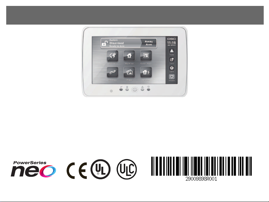
HS2TCHP
Installation Instructions/Instalační manuál/Installationsanleitung
WARNING: Please refer to the System Installation M anual for information on limitations regarding product use and fun ction and information on the limitations as to liability of the
manufacturer.
NOTE: These in structions shall be used in conjunction with the system Installation M anual of the Control Panel with which this equipment is intended to be u sed..
UPOZORNĚNÍ Tento manuál obsahuje in formace o omezení ve využívání výrob ku a jeho funk ci a také in formace o omezení o dpo vědno sti výrobce. Celý n ávod si pečlivě p řečtěte.
POZNÁMKA: Tyto pokyn y se p oužívají společně s Instalačním manu álem zabezpečovací ústředny, s níž se má toto zařízení používat.
WARNUNG: Siehe System-Installationsanleitung für Informationen zu Beschränkungen der Produktb enutzung und Funk tionen sowie Informationen zu den Haf-
tung sbeschränkun gen des Herstellers.
HINWEIS: Diese Installationsanleitung mu ss zusammen mit der Installationsanleitung d er Bedienfeld benutzt werden, an welcher das Gerät angeschlo ssen werden soll.
English
S
D
c
a
r
d
gently
push
in
press
to
eject
Installation Instructions
The HS2TCHP k eypad can b e u sed on security sy stems with u p to 128 zones. These
keypads are comp atible with the Neo PowerSeries HS2016/32/64 and HS2128 panels
V1.0 and higher.
Specifications
l Temperature range: UL/ULC: 0 °C to +49°C (32°F to 120°F); EN: -10 °C to +5 5°C
(14°F to 131°F)
l Weight: 405g
l Humidity (MAX): 93 %R.H. non-condens ing
l Plastic enclosu re protection degree: IP30, IK04 (touchscreen excluded)
l Voltage rating: 11.3VDC to 12 .5VDC nominal
l Low battery indication: 9VDC
l Conn ects to control panel via 4 -wire Co rbus
l Corbus distance: 101 m (332 ft.) (max.); Corbus distance in Extra Po wer mode: 54
m (177 ft)
l Up to 1 6 keypads per s ystem
l HS2TCHP current draw (at 12VDC): 100 mA standby (screen o ff)/160 mA activ-
ated o r alarm (reg. power mod e)/230 mA activated or alarm (Extra Power m ode).
l
Note: This d oes not include 50 mA (max) using PGM outpu t.
l Wall m ount tamp er
l Five programmable function keys
l Ready (Green LED), Armed (Red LED), Trouble (Yellow LED), AC (Green LED),
HOME (White LED)
l Keypad size: 191 m m x 126 mm x 20.3 5 mm
l Display area size: 155 mm x 86 mm
l SD card slot: h olds any standard SecureDigital (SD) card* (32 x 24 x 2.1 mm ). * If
necessary, the SD card can be formatted to file system FAT16 or 32 using a PC.
The maximum size SD card supp orted is 32 GB.
l Wiring: standard fou r-wire conn ection
l View angle: horizontal viewing ang le: 7 0° (left) (typ.) 70° (right) (typ.)
l Vertical v iew angle: 70° (top), 50° (bottom) (typ .)
l Brightness: 280 cd/m2
Unpacking
The key pad package in cludes the following parts:
l One k eypad
l Five mountin g screws and five anchors for wall-mounting
l One tamp er switch (required for UL commercial bu rglary listed installations)
l Installation instructions and Userm anual
Mounting
Mou nt the k eypad where it is accessible to d esignated points of entry and exit. Once a
dry and securelo cation is selected, do the following:
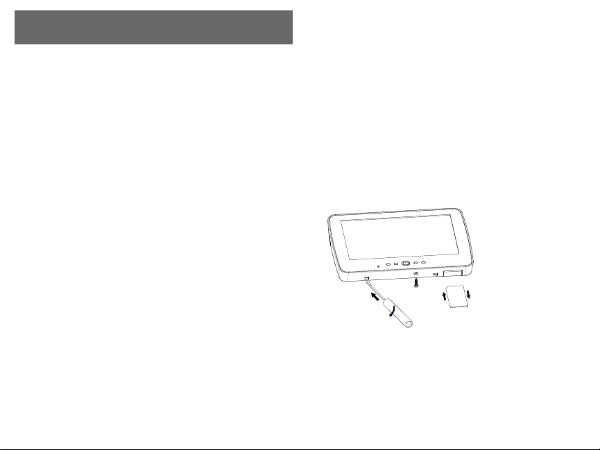
1.
Remove the SD card before o pening the touchscreen. See the following figure.
Warning: Do not disassemble the touchscreenw ithout removing the SD card
first.
2.
Remove screw at the botto m of the keypad.
3.
Insert screwdriver into slots and pry up to remov e.
Figure 1 - Removing the Backplate
4.
Secure keypad backplate to the wall u sing mo unting h oles. See the following figure. Use all 4 screws provid ed unless moun ting on a single g ang box . Use the
plastic anchors if the unit is to be moun ted on drywall. If using the keypad
tamper, secure the tamper plate to the wall with a screw.
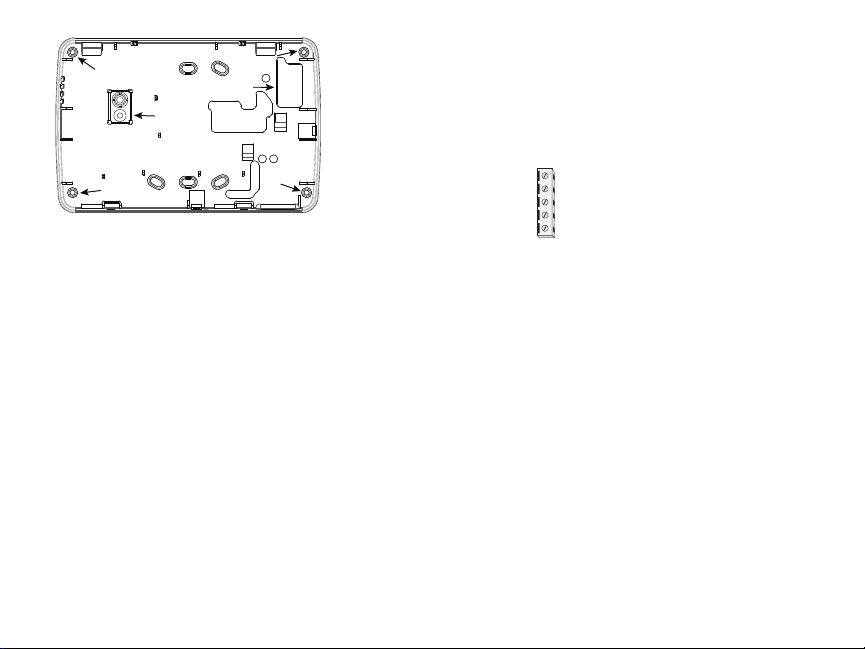
Figure 2 - Mounting the Backplate
mounting hole
mounting hole
mounting hole
wiring slot
mounting hole
hole for
tamper
screw
HS2TCHP
RED R
BLK B
YEL Y
GRN G
To zone or P/Z
PGM output
________
____
____
____
____
Note: For ULC fire ins tallations, the k eypad must be moun ted on top of an elec-
trical box and used with conduit.
5.
Run wire throug h wiring slot. Connect Corbus wiring to the keypad. See the Wiring section.
6.
Place keypad into backp late, ensu ring that the wire is push ed back in to the wall as
much as possible. Route the wire inside the keypad ensuring high comp onents are
avoided. Snap the front assembly closed, ensu ring that there is no pressure to the
keypad from the wire below.
If any tension is found between th e front keypad assembly and wiring, please op en the
keypad, re-route the wire and close again. Repeat these steps until the k eypad is closed
properly.
Wiring
1.
Before wiring th e u nit, ensure th at all power (AC transformer, telecommu nications
network, and battery) is dis connected from the control panel.
2.
Conn ect the four corbu s wires from the control p anel (green, yellow, b lack and red)
to the k eypad terminals.
3.
If programmed as an inp ut, a d evice, su ch as a door contact - may b e con nected to
the ‘P/Z’ terminal o f the keypad. This elimin ates th e need to run wires back to th e
control panel for the d evice. To connect the zon e, run one wire from the device to
the ‘P/Z’ terminal and the o ther wire from the device to the B (black) terminal. For
powered d evices, run the red wire to the R (po sitive) terminal and the black wire to
the B (negative) terminal.
4.
If the ‘P/Z’ terminal is prog rammed as an outpu t, a small relay (such as DSC model
RM-1 or RM-2) o r bu zzeror o ther DC operated device may be connected between
the positive supply voltage and the ‘P/Z’ terminal (max.load is 50m A).
Note: P/Z terminal is not to be used for fire applications bu t can be used for low
risk ULC commercial burglary applications.
Figure 3 - Wiring
Applying Power
Once all wiring is complete, and the equipment is secured to the b uilding structure with
at least two screws, apply power to the control panel.
1.
Conn ect the battery leads to the b attery.
2.
Conn ect the AC transformer.
3.
Conn ect telecommunication network (e.g., telephon e lin e, Ethernet cable, etc.)
For m ore information on con trol p anel p ower specifications, refer to the C ontrol Panel
installation manual.
Caution: Ro ute all the wiring according to the lo cal codes and regulations
Basic Setup
This section describes how to con figure the keypad, including enrollment, proxim ity tag
setup, function key assignm ent and label programming.
How to Program the Keypad
Programming consists of togglin g on and off optio ns in each section or b y popu lating
data fields. Toggle option s are enabled o r disabled b y pressing the corresponding number on the k eypad. For example, to enable toggle options 1 and 4 , press the [1] and[4]
keys. See the following diagram.
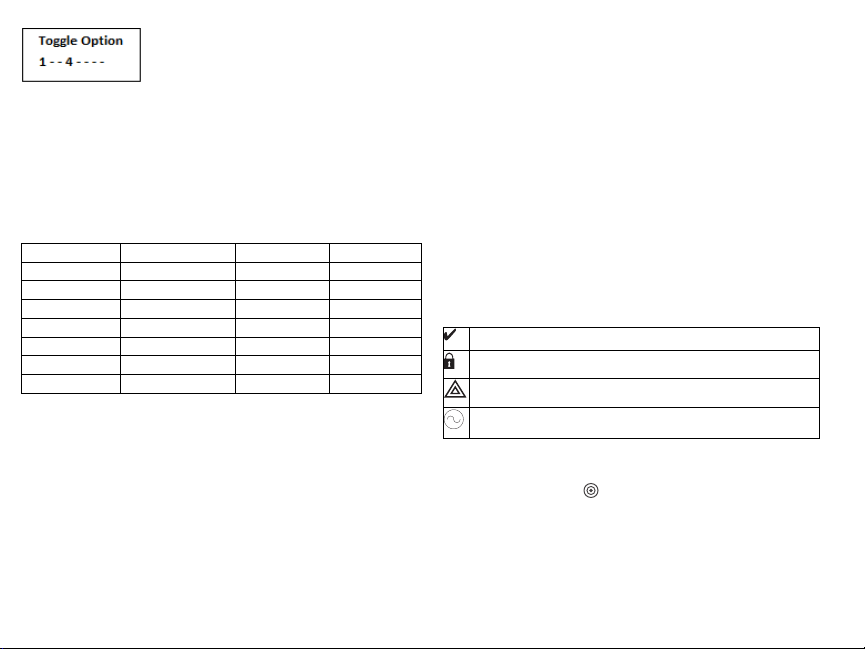
Togg le O ptions
To p rogram th e k eypad, press [*][8][Installer Co de] then use the [<][>] keys to navigate
through th e menus or ju mp directly to a specific section b y entering th e section n umb er.
To in put data, use th e [<][>] keys to select a character then p ress th e keypad button for the
num ber/letter.
Setting t he Keypad Language
Enter [000][000] then the two-digit langu age n umber.
Languages
01 = English 08 = Czech 16 = Turkish 25 = Ukrainian
(default) 09 = Finnish 17 = FFU 26 = Slovak
02 - Spanish 10 = G erman 18 = Croatian 27 = Serbian
03 - Portuguese 11 = Swedish 19 = Hungarian 28 = Estonian
04 - French 12 = Norwegian 20 = Romanian 29 = Slovenian
05 = Italian 13 - Danish 22 - Bulgarian
06 = Dutch 14 = Hebrew 23 = Latvian
07 = Polish 15 = Greek 24 = Lithuanian
Enrolling the Keypad
Keypads can be enrolled automatically or manu ally. In either case, the serial number of
the device is used as an identifier.
Note: If t here is no keypad enrolled on t he s ystem, once you power up, the keypad will display t he
message: Press the Enroll button on the touchscreen. Other keypads can then be e nrolled from the
first keypad. Use one of the following enrollment options:
[902][000] Auto Enroll
When this mode is selected, the total nu mber of keyp ads currently enrolled is dis played
on the keypad.
1.
Enter [902][000] to begin the auto -enrollment o f new keyp ads. As each device is
enrolled, the k eypad displays the model type, serial num ber and slot assig nment.
Keypads areassigned to the n ext available slot.
[902][001] Manual Enroll
1.
Enter [902][001] or use th e [<][>] k eys and press [*].
2.
When prompted, enter th e serial number of the keyp ad found on the back o f the
device.
3.
An error ton e is sou nded if an inv alid s erial numb er is received. Once enrolled, the
device m odel, serial num ber and slo t assignment are disp layed. Keypads are
enrolled into the next available slot for the device. The slot assignment can be
changed using the [<][>] k eys.
4.
To cancel the enrollment of a mo dule, press [#].
Note: Once the maximum number of devices have been enrolled, an error tone s ounds and a warning
message is displayed.
[902][101] Unenroll Keypads
1.
Enter [902][101] or use th e [<][>] k eys and press [*].
2.
Use the [<][>] keys to scroll to the specific keypad to d elete.
3.
Press [*] to select the keyp ad and, when p rompted, press [*] again to delete it.
Keypad Display Symbols
Ready Light (green) – If the Ready light is on, the system i s ready for arming.
Armed Light (red) – If the Armed light i s on, the system has been armed success fully.
System Trouble – Indicates that a system trouble is active.
AC – Indicates that AC is present at the main panel.
Proximity (Prox) Tags Support
The tag can p erform any keypad function that would normally require a u ser access cod e.
Present the tag to the tag reader .
Assign Proximity Tags
Using an LCD keypad:
1.
Press [*][5]Master/Superviso r Cod e].
2.
Enter a 2 -digit user code.
3.
Press 2.
4.
Pass the enrolled tag nearth e tag reader.

DeleteProximity Tags
To d elete a proximity tag:
1.
Select Options, Access Co des [enter Master code].
2.
Select a u ser to delete.
3.
Select Prox Tag Prog then delete.
Function Key Assignment
The HS2TCHP h as 7 b uttons on the Home screen, four of them programmable by the
installer. Fun ction key 2 must always be set to "Away Armed."
To p rogram fun ction keys 1,3,4 ,5:
1.
On the virtual keypad, press [*][8][Installer Co de].
2.
Enter [861]-[876] to program k eypads 1-16 respectively.
3.
Enter [001-[005] for function keys 1-5 or u se the [<][>] keys and press [*].
4.
Enter a 2 -digit number to assign a fun ction key operation - [00]-[68]. See Available
Function Key Options below.
5.
Repeat from step 3 u ntil function keys 1, 3, 4, 5 are p rogrammed.
To p rogram fun ction key 6:
1.
Press Option s, InstallerM enu [InstallerCo de], Keyp ad Programming then Home
Functions.
2.
To d isplay the Photo button o n the Hom e p age, press Photo s. To display the
Keypad Mode butto n on the Home p age, press Keypad Mode.
Available Function Key Options
Referto yo ur system installation manual for a comp lete list.
[00]N ull [02]Inst ant S tay Arm [03]S tay Arm
[04]A way A rm [05] [*][9] N o-entry A rm [06] [*][4] Chime ON/OFF
[07][*][6][---][04] S ystem Tes t [09]N ight Arm [12]G lobal S tay Arm
[13]G lobal Aw ay Arm [14]G lobal Di sarming [16] [*][0] Quick Exit
[17]A rm Interior [21] [*][7][1] Command O utput 1 [22] [*][7][2] Command O utput 2
[23][*][7][3] Command Output 3 [24] [*][7][4] Command O utput 4 [29] Bypass Group Recall
[31]Local PGM Activate [32] Bypass Mode [33]Bypass Recall
[34]U ser Programming [35] User Functions [37] Time/ Dat e Program
[39]Trouble D isplay [40] Alarm Memory [61] - [68] P artition S elect 1 - 8
Programming Labels
1.
From the HS2TCHP k eypad, press Options, press Installer M enu [Installer Co de],
then press Label Prog ramming.
2.
From the Label s creen, press the item that y ou want to label (e.g., zones, partition s,
etc.).
3.
Enter the label name for the selected item.
4.
Press Save when com plete.
Optional Settings
The following setting s are available throug h the Options menu.
Enable/Disable Fire, Medical, Panic Buttons
1.
Press Option s, InstallerM enu [InstallerCo de], Keyp ad Programming, then
Options.
2.
Enable/disable th e d esired Fire, M edical and Panic button s.
Extra Power Option
The Extra Powero ption will increase th e b rightness of the disp lay. To enable the option:
1.
Press Option s, InstallerM enu [InstallerCo de], Keyp ad Programming, then
Options.
2.
Enable or disable the extra po wer option .
Note: Enabling the Extra Power option w ill put the keypad into a higher current mode and the
keypad will draw 300 mA. In Extra P ower mode, reduce the maximum wire length from 101 m (332
ft.) to 54 m (177 ft. )
Change the Background Image
1.
Press Option s, InstallerM enu [InstallerCo de], Keyp ad Programming, then Background Image.
2.
Select image to u se from SD card as backgrou nd image.
3.
To exit, press the B ack o r the Home button.
Dark Text Enable/Disable
1.
Press Option s, InstallerM enu [InstallerCo de], Keyp ad Programming, then
Options.

2.
Select the desired text color by enabling or d isabling Dark Text. (This will make
the text white).
Note: This feature a ffects o nly thetext on theClassic (square) button home page.
Perform a Firmware Upgrade
1.
Insert an SDcard in the HS2TCHP with the new firmware.
2.
Press Option s, InstallerM enu [InstallerCo de], Keyp ad Programming, then Firmware Upgrade.
3.
Select OK to perform a firmware upg rade (if a new firmware v ersion is available).
Keypad Programming
To enter k eypad programming:
1.
Press Options then Key pad Mode. The virtual keypad is displ ayed.
2.
Press [*][8][Installer Code].
3.
Enter one of the following keypad programming s ections:
l [860] Key pad Sl ot Number. This secti on i s for dis play only.
Once a k eypad is selected, the fol lowing programming options are av ailable:
[000]Keypad PartitionMask
Valid en triesare 0 0-08. |___ |__ _|
[011]Keypad Input/Output Programming
Zoneor PGM Number Default 000 I___I___I___I
[012]Local PGM O utputPulse Activation Time
I___I___I Minutes (00-99) I___I___I
[021]FirstKeypad Options
Default Value Option ON Off
ON I__I 1 Fire KeyEnabled F ireKey Disabled
ON I__I 2 MedicalKeyEnabled MedicalKey Disabled
ON I__I 3 PanicKey Enabled PanicKey Disabled
ON I__I 4
[022]Second Keypad Options
Default Value Option ON Off
ON I__I 1 LocalClockDisplayO N Local Clock DisplayO FF
OFF I__I 2 LocalClockDisplays24-hr ClockDisplaysAM/ PM
l [861]-[876] to program keypads 1-16 respecti vely.
Seconds (00-99)
DisplayAccess CodeWhenProgramming
DisplayXs W henProgramming
AccessCodes
Default Value Option ON Off
ON I__I 3 Auto AlarmMem ScrollON Auto AlarmMem ScrollOF F
ON I__I 4 For Future Use For FutureUse
OFF I__I 5 PowerLEDEnabled Power LEDDisabled
ON I__I 6
ON I__I 7 AlarmsDisplayedW hile Armed AlarmsNot DisplayedWhileArmed
OFF I__I 8 Auto-ScrollOpenZonesO N Auto-Scroll OpenZonesO FF
Note:For UL/UL C installations, b it5 (PowerLED)an d bit 6 (Power LED Ind icatesAC Present)
shallbe ON.
[023]Third Keypad Options
Default Value Option ON Off
OFF I__I 1 ArmedLED Power Save ArmedLEDO ff in SleepMode
ON I__I 2 KeypadStatus Shows Stay Arm
OFF I__I 3
ON I__I 4 Prox tagwillarm/disarm Prox tag does not arm/disarm
OFF I__I 7 LocalDisplayof T emperature NoLocalDisplay of Temperature
OFF I__I 8 LowTemperatureWarningEnabled LowT emperatureWarningDisabled
Power LEDI ndicatesAC PresentONPower LEDI ndicatesAC Present
5thT erminalis KeypadPGM Output
OFF
Keypad Status Shows Stay/Away
Arm
5thT erminalis KeypadZoneInput
[030]Download LCD Messages
I___I___I___I___I___I___I___I___I___I___I___I___I___I ___I
I___I___I___I___I___I___I___I___I___I___I___I___I___I ___I
[031] Download LCD Message Duration
Default: 000 I___I___I___I
(Valid ent riesare 00 0-255, 000=Un limited M sg Display)Thisnu mbe rrep resents the n umb er
of times the download ed m essage mu stb e cleared be fore it isperm anen tlyremo ved. This
message can be cleared by pressinga ny key.
[041]Indoor Temperature Zone Assignment
Default: 000 I___I___I___I
(Valid entries are 000-128)
[042]Outdoor Temperature Zone Assignment
Default: 000 I___I___I___I
[101] - [228] Door Chime for Zones 1 - 128
The keypad can be program me d to m ake up to four different chime sounds for individua l
zones (e.g., forZon e 1, e nter section [10 1], for Zon e 2 en ter section [102 ]).
Default: 01 I___I___I
(Valid entries are 000-128)

Valid Entries
01 6Beeps
02 Bing-Bingtone
03 Ding-Dong tone
04 Alarmtone(4 secondduration)
05 Zonename
[991] Reset K eypad Programming to Factory Defaults
1.
Press [*][8][Installer Code].
2.
Enter [991].
3.
Use the [<][>] key s to s croll to the applicabl e keypad.
4.
Press [*] to selec t the keypad.
5.
Re-enter [Ins taller Code].
6.
Press [*] to reset the selec ted k eypad to factory defaults.

Limited Warranty
Digita l Security Controls (DSC) warrants t hat for a period of 12 months from the date of purchase, the
product shal l be free of de fects in ma teri als and workmanship under norm al use and tha t in fulfilm ent
of any bre ach of such warranty, DSC shall, a t its option, re pair or repl ace the defect ive equipment upon
return of the equipme nt to its re pair depot. Thi s warra nty applie s onl y t o defect s in parts a nd workmanship and not to da mage incurred in shippi ng or handling, or dam age due t o c auses beyond t he control of Digit al Securi ty Controls such a s li ghtning, excessive voltage, mecha nica l shock, wate r da mage ,
or damage arising out of abuse, al tera tion or imprope r applica tion of the equipme nt. T he foregoing warranty shal l apply only to the original buyer, and is and shall be in l ieu of any and a ll other warra ntie s,
whether expressed or implie d a nd of al l other obligati ons or lia bilit ies on t he part of Digi tal Security
Controls. Digi tal Security Controls ne ithe r a ssumes re sponsibilit y for, nor a uthoriz es any ot her person
purporting to a ct on its behal f t o modify or t o c hange this warra nty, nor to a ssume for it any other warranty or li abili ty conce rning this product. In no event shall Digit al Sec urity Controls be liable for a ny
direc t, i ndirec t or c onsequenti al damages, l oss of antic ipat ed profits, l oss of time or any other losses
incurre d by the buyer in c onnect ion with the purchase, i nstall ati on or opera tion or fai lure of this
product.
Warni ng: Digital Security Controls re comm ends t hat the entire system be comple tel y t ested on a regular basis.However, despite frequent testi ng, and due t o, but not li mit ed to, c rimi nal tamperi ng or electric al disruption, it is possible for thi s produc t to fail to perform as e xpect ed. Im portant Informati on:
Changes/m odific ati ons not expressly a pproved by DSC could void the user’s aut hority to opera te this
equipm ent.
IMPORTANT - READ CAREFULLY: DSC Software purchased with or without Products and Components is c opyrighted and is purchased under the following l ice nse te rms:
This End-User L ice nse Agreement (“EULA”) is a legal agreeme nt between You (the company, individual or e ntity who acqui red the Software and a ny relate d Hardware) a nd Digital Security Controls, a
division of Tyc o Safe ty Products Ca nada Ltd. (“DSC”), the manufac turer of the integrat ed securit y system s a nd t he develope r of t he software and a ny relate d products or components (“HARDWARE”) which
You a cquire d.
If the DSC software product (“SOFTW ARE PRODUCT” or “ SOFTWARE” ) is i ntended to be accom panie d by HARDWARE, and is NOT a ccom panie d by new HARDWARE, You m ay not use, copy or
instal l the SOFTWARE PRODUCT. The SOFTWARE PRODUCT inc ludes compute r software, and may
incl ude associate d media , print ed mate rial s, and “online ” or e lec tronic document ati on.
Any software provided along with the Software Product that is a ssociate d with a separate end-user
lic ense agreem ent is li censed to You under the terms of t hat license agreeme nt.
By installi ng, copyi ng, downloa ding, stori ng, ac cessing or ot herwise using t he Software Product, You
agree unconditi onall y t o be bound by the terms of t his EULA, even if t his E ULA i s de emed to be a
modifi cat ion of a ny pre vious arrangem ent or contra ct. If You do not agree to t he terms of t his EULA,
DSC is unwilling to l ice nse t he Software Product to You, and You have no right to use it.
SOFTWARE P RODUCT LICENSE
The SOFTWARE PRODUCT is prote cte d by copyri ght laws a nd interna tional copyright treati es, as well
as other intel lec tual property laws a nd t reat ies. T he SOFTWARE PRODUCT i s l ice nsed, not sold.
1. GRANT O F LICENSE T his EULA grant s You the following rights:
(a) Software Installation and Use - For eac h lice nse You acqui re, You may have only one copy of the
SOFTW ARE PRODUCT i nstall ed.
(b) Storage /Network Use - The SOFTWARE PRODUCT ma y not be install ed, a cce ssed, displaye d, run,
shared or used concurrentl y on or from different compute rs, incl uding a worksta tion, termina l or other
digit al elect ronic device (“Device” ). In other words,i f You have seve ral workstat ions, You wil l have t o
acqui re a lice nse for each workstation where the SOFTWARE will be used.
(c) Backup Copy - You ma y make back-up c opies of t he SOFTWARE PRODUCT, but You may only
have one c opy pe r lice nse i nstall ed at any give n time. You ma y use the back-up copy solely for
archi val purposes. E xcept as expre ssly provi ded in this EULA, You ma y not ot herwise make copies of
the SOFTWARE PRODUCT, inc luding the printed materia ls accom panying the SOFTWARE.
2. DESCRIPTION OF OTHER RIGHTS AND LIMITATIONS
(a) Limitations on Reverse Engineeri ng, Decompilati on and Disassembly - You may not reverse engin-
eer, decompi le, or disassembl e the SOFTWARE PRODUCT, e xcept and onl y to t he exte nt that such
act ivit y i s e xpressly permitt ed by a pplic able law notwithstandi ng t his limit ati on. You may not make
any changes or modifi cat ions to t he Software, wit hout the written permission of an officer of DSC. You
may not re move any proprie tary notices, m arks or la bels from the Software Product. You shall institut e
reasonabl e measures to ensure compli ance with t he terms and condi tions of t his EULA.
(b) Separati on of Components - The Software Product is l ice nsed a s a single product. Its com ponent
parts may not be sepa rate d for use on more than one HARDWARE unit.
(c) Single INTEGRATED PRODUCT - If you acquire d this SOFTWARE with HARDWARE, t hen the
SOFTW ARE PRODUCT i s l ice nsed wit h the HARDWARE as a single inte grate d produc t. In this c ase,
the SOFTWARE PRODUCT may only be used wit h t he HARDWARE a s set forth i n this E ULA.
(d) Rental - You may not re nt, l ease or le nd t he SOFTW ARE PRODUCT. You m ay not make it available to others or post it on a serve r or web site.
(e) Software P roduct Transfer - You may transfer a ll of Your rights unde r this E ULA onl y a s pa rt of a
perma nent sal e or t ransfer of t he HARDWARE, provi ded You ret ain no copi es, You transfer all of the
SOFTW ARE PRODUCT (i ncludi ng all component parts, the media and print ed mat erial s, any upgrades
and this EULA), and provided the re cipi ent agrees to t he terms of this EULA. If the SOFTW ARE
PRODUCT is a n upgrade, a ny t ransfer must also include all prior versions of t he SOFTWARE
PRODUCT.
(f) Termination - W ithout prejudice to any ot her rights, DSC may termina te this E ULA i f You fail to
compl y wit h the terms and conditi ons of this EULA. In such e vent, You must destroy all copies of the
SOFTW ARE PRODUCT a nd all of its compone nt parts.
(g) Trademarks - This EULA doe s not grant You any rights in connecti on with a ny tradem arks or service marks of DSC or its suppli ers.
3. COPYRIGHT - All titl e and intel lec tual property rights in a nd to t he SOFTW ARE PRODUCT
(incl uding but not l imi ted to a ny i mage s, photographs, and t ext incorporate d into the SOFTWARE
PRODUCT), t he accom panying printed mat erial s, and any copi es of the SOFTWARE PRODUCT, are
owned by DSC or its suppli ers. You may not c opy the printed materi als accom panying the SOFTWARE
PRODUCT. All titl e and intel lec tual property rights in a nd to t he content which may be acce ssed
through use of the SOFTWARE PRODUCT are the property of t he respecti ve conte nt owner a nd m ay be
protec ted by appli cabl e copyright or othe r intel lec tual property laws a nd t reat ies. T his EULA grant s
You no rights to use such conte nt. All rights not expressly granted under t his E ULA a re reserved by DSC
and its suppliers.
4. EXPORT RESTRICTIONS - You agree that You will not export or re -export the SOFTWARE
PRODUCT to any c ountry, person, or e ntit y subject to Cana dian export restricti ons.
5. CHOICE OF LAW - This Software License Agree ment is gove rned by t he laws of the Provinc e of
Ontario, Canada.
6. ARBITRATION - All disputes a rising in connect ion with this Agreement shal l be determ ined by
final and binding arbitra tion in ac cordanc e with the Arbitrati on Act, and the parties agree to be bound
by the arbitra tor’s de cision. The plac e of a rbitra tion shall be Toronto, Ca nada, and t he language of t he
arbit rati on shal l be English.
7. LIMITED WARRANTY
(a) NO WARRANTY - DSC PROVIDES THE SOFTWARE “AS IS” WITHOUT WARRANTY. DSC
DOES NOT W ARRANT THAT THE SOFTWARE WILL MEET YOUR REQUIREMENTS OR THAT
OPERATION OF THE SOFTWARE WILL BE UNINTERRUPTED OR ERROR-FREE.
(b) CHANGES IN OPERATING ENVIRONMENT - DSC shal l not be responsible for probl ems caused
by changes in the operati ng c harac teri stics of t he HARDWARE, or for problems in the intera cti on of
the SOFTWARE PRODUCT with non-DSC-SOFTWARE or HARDWARE PRODUCTS.
(c) LIMITATION OF LIABILITY; WARRANTY REFLECTS ALLOCATION O F RISK - IN ANY

EVENT, IF ANY STATUTE IMPLIE S WARRANTIES OR CONDITIONS NOT
STATED IN THIS L ICENSE AGREEMENT, DSC’S ENTIRE LIABILITY UNDER ANY PROVISIONOF
THIS L ICENSE AGREEMENT SHALL BE LIMITED TO THE GREATER OF THE AMOUNT
ACTUALLY PAID BY YOU TO LICE NSE T HE SOFTWARE PRODUCT AND FIVE CANADIAN
DOLLARS (CAD$5.00).BE CAUSE SOME JURISDICTIONS DONOT ALLOW THE E XCLUSION OR
LIMITATION OF LIABILITY FOR CONSEQUENTIAL OR INCIDENTAL DAMAGES, T HE ABOVE
LIMITATION MAY NOT APPLY TO YOU.
(d) DISCLAIMER O F WARRANTIES - T HIS WARRANTY CONTAINS THE ENTIRE W ARRANTY
AND SHALL BE IN LIEU OF ANY AND ALL OTHER W ARRANTIE S, WHETHER EXPRESSED OR
IMPLIED (INCLUDING ALL IMPLIED WARRANTIE S OF MERCHANTABILITY OR FITNESS FOR A
PARTICULAR PURPOSE) AND OFALL OTHER OBLIGATIONS OR LIABILITIES ON THE PART OF
DSC.DSC MAKES NO OTHER W ARRANTIES. DSC NEITHER ASSUMES NOR AUTHORIZE S ANY
OTHER PERSON PURPORTING TO ACT ON IT S BE HALF TO MODIFY OR T O CHANGE T HIS
WARRANTY,NOR TO ASSUME FOR IT ANY OTHER WARRANTY OR LIABILITY CONCERNING
THIS SOFTWARE PRODUCT.
(e) EXCLUSIVE REMEDY AND LIMITATION OF WARRANTY - UNDER NO CIRCUMSTANCES
SHALL DSC BE LIABLE FOR ANY SPECIAL, INCIDENTAL, CONSEQUENTIAL OR INDIRECT
DAMAGES BASED UPON BREACH OF WARRANTY,BRE ACH OF CONTRACT, NEGLIGENCE,
STRICT LIABILITY, OR ANY OTHER LE GAL T HEORY.SUCH DAMAGES INCLUDE, BUT ARE NOT
LIMITED TO, LOSS OF PROFITS, LOSS OF T HE SOFTWARE PRODUCT OR ANYASSOCIATED
EQUIPMENT, COST OF CAPITAL, COST OF SUBSTITUTE OR REPLACEMENT EQUIPMENT,
FACILITIES OR SERVICES, DOWN TIME, PURCHASERS TIME, THE CLAIMSOF THIRD PARTIES,
INCLUDING CUSTOMERS, AND INJURYT O PROPERTY.
WARNING: DSC re comm ends that the e ntire syste m be comple tely tested on a regula r ba sis. However,
despite frequent testing, a nd due t o, but not l imi ted to, crim inal tampe ring or e lec tric al disruption, it is
possible for t his SOFTWARE PRODUCT to fail to perform as e xpect ed.
Operati ng Instructions shall be made avail able to the user.
The tradema rks, logos, and service marks displayed on thi s doc ument are registere d i n the United State s
[or other countrie s]. Any m isuse of the tradem arks i s stri ctl y prohibited and T yco Internat ional Ltd. wil l
aggressivel y enforce its intel lec tual property rights to t he fulle st e xtent of t he law, inc luding pursuit of
crim inal prosecution where ver necessary. All tradem arks not owned by Tyc o Internati onal Ltd. are the
property of the ir respecti ve owners, and are used wit h permission or a llowed under appl ica ble laws.
Product offerings and spec ific ati ons are subject to c hange wit hout notice . Actua l products may vary
from photos. Not all products i nclude all features. Avai labi lit y va ries by re gion; contact your sal es re presenta tive .
This product conta ins ope n source c omponent s QT Version 4.7.3 and Linux Kernel Lice nse: Version 2.6.
Both of t hese component s a re protect ed by c opyright and ha ve terms and conditi ons a ssociate d wit h
thei r use. The open source software code and associate d components used i n this product are downloada ble from the DSC website. Please visit
http: //www.dsc.com/ open-source-doc umenta tion for det ail ed informat ion.
FCC Compliance Statement - CAUTION: Changes or modifica tions not expressly approved by DSC
could void your authority to use this equipme nt.
This equipme nt genera tes and uses radio frequency energy and if not i nstall ed and used properl y, i n
strict accorda nce wit h t he manufac turer’s instructions, m ay cause interfe rence to radio and televi sion
rece ption. It ha s be en type tested and found to comply with the limi ts for Cla ss B device in accorda nce
with the specifi cat ions i n Subpart “ B” of Part 15 of FCC Rules, whic h a re designed to provide reasonable protect ion against such interfere nce in any residentia l instal lat ion. However, there is no guarante e that interfere nce wil l not occur in a pa rtic ular installa tion. If thi s e quipme nt does c ause
inte rferenc e to televi sion or ra dio recept ion, whic h can be determi ned by t urning the equipment off
and on, the user is encouraged to try to c orrect the inte rference by one or m ore of t he following
mea sures:
• Re -orient the rece iving antenna
• Re loca te the alarm control with respect to the recei ver
• Move the alarm control away from the recei ver
• Conne ct the alarm control into a different outlet so tha t alarm control and re cei ver are on di fferent
circ uits.
If necessary, t he user should consult t he dealer or a n experie nced radio/te levisi on t echni cia n for addi tiona l suggestions. The user ma y find t he following booklet prepared by the FCC helpful : “How to
Identi fy and Re solve Radio/T ele vision Interfere nce Problems”. T his bookl et is ava ila ble from the U.S.
Government Printing Office, Washington, D.C. 20402, Stoc k # 004-000-00345-4.
Ind ustry Canada Compl iance Statement
CAN ICES-3(b)/NMB-3(b)
For Co mmercial Fire M onitoring applications the HS2TCHP k eypad is for supp lementary
use only.
EN50131-1 Grade2/Class II
The M odel HS2TCHPKeypad has been certified by Telefication accordin g to
EN50131-1:2006 + A1:2009 , EN50131-3:2009 for Grade 2 , Class II.
Notes:For EN501 31 compliant installations the following functions (initiated from
the keypad emergency b uttons ) have to be d isabled:
- Fire Alarm fun ction
- Auxiliary (Medical) Alarm function
- Panic Alarm function
©20 16 Tyco Security Products. All Rights Reserved • www.dsc.com •
Tech Supp ort: 1 -800-387 -3630 (Canada, US), 905-76 0-3000

Česky
Klávesnice HS2TCHP lze pou žít v zabezpeč ovacích systémech až d o 128 zón v systému.
Tyto klávesnice jsou kompatibilní s ústřednami HS2016/32/64 a HS20128 v1.0 a novější.
Specifikace
• Rozsah p racovních teplot 0°C až +49°C
• Hmotnost: 405g
• Vlhkost (max.) 93% nekondenzující
• Krytí IP30, IK04 (kromě dotykového displeje)
• Napájecí napětí 11,3-12,5V
• Signalizace vybité baterie 9V
• Připojení k ústředně pomocí 4-vodičové sběrnice Corbus
• Délka sběrnice ke klávesnici max. 101m;
max. 54m; zvýšené podsvícení povoleno
• Počet klávesnic v systému max. 16 (nutné zajistit odpovídající napájení)
• Proudov ý odběr 100mA (displej vypnut)
160mA (displej zapnut, alarm)
230mA (displej zapnut, alarm-zvýšené podsvícení)
Poznámka: Do proudového odběru není započítáno50mA (max.) týkající se PGM
• Tamper kontakt proti sundání ze zdi
• 5 programovatel ných funkčních tlačítek
• Kontrolky Připr aveno (zelená LED), Za pnuto (červená LED), Porucha (žlutá LED),
AC síť (zelená LED) a Domů (bílá LED)
• Rozměry klávesnice 191 x 126 x 20,35mm (š x v x h)
• 7" barevný dotykový displej 155 x 86mm (š x v)
• Slot pro SD kartu (aktualizace FW, prohlížení fotografií). SD kartu lze v případě
potřeby naformátovat v PC a FAT16 nebo FAT32. Maximální velikost podporované
SD kart y je 32GB.
• Kabeláž klasické 4 vodiče
• Horizontální pozorovac í úhel 70° (typicky)
• Vertikální pozorovací úh el 70° (ze shora) a 50° (ze spodu)
• Jas 280cd/m2
Obsah balení
Jedno balení klávesnice obsahuje následující součásti:
• Jednu klávesnici
• Pět šroubů a pět hmoždinek pro montáž
• Jeden Tamper kont akt
• Jeden ins talační manuál a u živa t e ls k ý manu á l
Instalační manuál
DC
DC
Montáž
Klávesnici byste měli upevnit na místě, které je při příchodu a odchodu snadno přístupné.
Jakmile máte vybráno suché a bezpečné místo, proveďte montáž klávesnice podle
následu jících kroků:
1. Vyjměte SD kartu před tím, než rozeberete klávesnici (viz. obrázek 1)
Varování: Pokud před rozebráním klávesnice nevyjmete SD kartu, dojde k poškození
klávesnice
2. Vyšroubujte šroubek ve spodní části klávesnice
3. Vložte plochý šroubovák do otvorů ve spodní části klávesnice a pak pohybem
šroubováku uvolněte přední část klávesnice z plastových zad.
Obrázek 1: Rozebrání klávesnice
4. Upevněte zadní kryt klávesnice na stěnu, využijte připravené montážní otvory (viz.
obrázek 2). Použijte vš echny čtyři do dané šrouby. Pokud se k lávesnice přip evňuje na
sádrokartonovou desku, použijte dodané plastové hmoždinky. Při použití tamperu
klávesnice, upevněte destičku s tamperem na stěnu pomocí šroubku.
Obrázek 2: Montáž zadního kryt u
5. Otvorem pro přívodní vodiče přiveďte do klávesnice sběrnici a připojte ji do
svorkovnice (viz. kapitola Zapojení vodičů).
6. Umístěte klávesnici do zadního krytu, ujistěte se, že je kabel pokud možno co nejvíce
zasunutý do zdi. Veďte kabel vnitřkem klávesnice, přičemž se ujistěte, že se vyhýbá

součástkám. Zaklapněte přední část klávesnice, přičemž se přesvědčte, že kabel ve
01 = Anglicky
09 = Finsky
10 = Německy
19 = Maďarsky
20 = Rumunsky
29 = Slovinsky
spodní části klávesnice není skřípnutý.
POZNÁMKA: Pokud zjist íte jakékoli napětí mez i přední částí klávesnice a kabelem,
otevřete prosím klávesnici, změňte pozi ci kabelu a znovu ji zavřete. Tyto kro ky opakujte
tak dlouho, dokud nepůjde klávesnice snadno zavřít.
Zapojení vodičů
1. Před připojením klávesnice musí být od ústředny odpojeno veškeré napájení (baterie,
transformátor, telefonní linka).
2. Připojte čtyři kabely sběrnice Corbus vedoucí z ústředny (červený, černý, žlut ý a
zelený) ke svorkám klávesnice. Viz obrázek 3.
3. Jestli že je svorka "P/Z" na stavena jako zónov ý vstup, t ak na tuto svorku lze zapojit
výstupní kontakt libovolného zařízení (např. magnet). Tím se eliminuje nutnost vést
vodiče zpátky do ústředny. Pro připojení zóny veďte jeden vodič ze zařízení ke svorce
P/Z a druhý ke svorce B (černá). V případě napájených zařízení veďte červený vodič
ke svorce R (+12V) a černý vodič ke svorce B (GND). Na této zóně se používá stejné
zakončení jako na ostat ních zónách v systému.
Poznámka: Zařízení zapojené do tohoto vstupu nesmí sloužit pro detekci nouze nebo
požáru.
4. Jestliže je svorka "P/Z" nastavena jako výstup, tak může být malé relé, bzučák nebo
jiné zařízení připojeno mezi svorku R (+12V) a svorku P/Z (maximální zatížení je
50mA).
Obrázek 3: Svorkovnice
Připojení ke zdroji
Jakmile jsou zapojeny všechny vodiče a klávesnice je upevněna alespoň pomocí dvou
šroubů, připojt e napájecí nap ětí k ústředně v následujícím p ořadí:
1. Připojte kabeláž k baterii.
2. Připojte s íťový transformátor.
3. Připojte telefonní linku
Více informací o elektrických specifikacích ústředny najdete v instalačním manuálu.
UPOZORNĚNÍ: Vodiče musí být vedeny v souladu s místními zákony a předpisy.
Základní nastavení
Tato čá st popisuje, jak naprogr amovat kláves nici, včetně přihláš ení, správu pr oximity
přívěšků nasta vení funkčních kláves a progra mování názvů.
Programování klávesnice
Při progr amování sekc í se buď progra mují volby, které lz e povolit/zaká zat, nebo se
očekává vkládání nějakých úda jů. Pro zapnutí nebo vypnutí volby stiskněte na klávesnici
číslici odpovídající volby. Například, pro zapnutí voleb 1 a 4, stiskněte klávesy [1] a [4].
Na klávesnici jsou zobrazeny všechny zapnuté volby (viz. následující obrázek).
Nastavení funkc e
1. Stiskněte [*][8][Instalační kód].
2. Pomocí tla čítek [<][>] listujte mezi položkami menu, nebo pří mo přej děte do
požadované sekce vložením jejího čísla.
3. Chcete-li vložit data, nalistujt e pomoc í tlačítek [<][>] požadovanou pozici a p oté
stiskněte tlačítko na klávesnici odpovídající vkládanému číslu/písmenu.
4. Pomocí t lačítek [<][> ] se přesuňte na další znak a postup opa kujte. Informa ce o
způsobu zadávání hexadecimálních údaje naleznete v instalačním manuálu ústředny.
Volba jazyka
Zadejte [000][000]. Vložte dvoumístné číslo, které odpovídá požadovanému jazyku:
Jazyky
(výchozí)
02 = Španělsky
03 = Portugalsky
04 = Francouzsky
05 = Italsky
06 = Holandsky
07 = Polsky
08 = Česky
Přihlášení klávesnice
Klávesnice může být přihlášena automaticky nebo manuálně. V obou případech je sériové
(identifikační) číslo za řízení použit o jako jeho id entifikátor.
Poznámka: Pokud v systému není přihlášená žádná klávesnice, tak se po zapnutí
napájení, na klávesnici zobrazí text: Press the enroll button on the touchscreen (Stiskni
tlačítko přihlášení na dotykové klávesnici). Další klávesnice lze pak přihlásit z první
přihlášené klávesnice. Pro přihlášení lze použít jeden z následujících postupů:
[902][000] Automatické přihlášení
V tomto režimu bude na klávesnici zobrazen celkový počet klávesnic přihlášených v
systému.
11 = Švédsky
12 = Norsky
13 = Dánsky
14 = Hebrejsky
15 = Řecky
16 = Turecky
17 = nepoužito
18 = Chorvatsky
21 = Rusky
22 = Bulharsky
23 = Lotyšsky
24 = Litevsky
25 = Ukrajinsky
26 = Slovensky
27 = Srbsky
28 = Estonsky

1. Zadejte [902][000] pro zahájení automatického přihlášení nových klávesnic. Při
Napájení (zelená) - Signalizuje, že je ústředna napájena střídavým
napětím.
přihlášení každého zařízení se na klávesnici zobrazí jeho typ, sériové číslo a přiřazený
slot. Klávesnice jsou přiřazeny na první volný slot.
[902][001] Manuální přihlášení
1. Zadejte [902][001], nebo použijte tlačítka [<][>] a stiskněte [*].
2. Po zobrazení výzvy zadejte sériové číslo klávesnice, které se naleznete na její zadní
stra ně.
3. Pokud vl ožíte chybné s ériové (identifikační ) číslo, ozve se chybov ý tón. Po přihlá šení
se zobrazí typ zařízení, sériové (identifikační) číslo a přiřazený slot. Klávesnice jsou
přiřazeny na první volný slot. Přiřazený slot lze změnit pomocí tlačítek [<][>].
4. Chcete-li ukončit režim přihlašování modulů, stiskněte [#].
Poznámka: Jakmile dojde k přihlášení maximálního počtu zařízení, ozve se chybový tón a
zobrazí se výstražná zpráva.
Přiřazení klávesnice do bloku
Klávesnic e mus í být přiřazeny do bloků. Přiřazení klávesnice do bloku a její
naprogramování musí být provedeno pro každou přihlášenou klávesnici.
1. Stiskněte [*][8][Instalační kód].
2. Zadejte [861] - [876] pro programování klávesnice 1-16.
3. Stiskněte [*] pro přiřazení klávesnice do bloku.
4. Zadejte 01 až 08 pro přiřazení klávesnice do bloku 1-8 nebo požadovaný blok
nalistujte pomocí kláves [<] [>] a stiskněte [*]. Pokud s ystem není rozdělen do b loků,
vložte [01]. Pro globální (společnou) klávesnici, zadejte [00].
5. Stiskněte dvakrát tlačítko [#]pro ukončení programování.
6. Zopakujte tento postup pro každou klávesnici, dokud nebudou všechny přiřazeny do
správného bloku.
[902][101] Vyjmutí klávesnice
1. Zadejte [902][101], nebo použijte tlačítka [<][>] a stiskněte [*].
2. Pomocí tla čítek [<][>] nalistujte klávesnici, kterou chcete vyjmout ze systému.
3. Vyberte ji stiskem [*] a po zobrazení výzvy stiskněte [*] pro její vyjmutí.
Připraveno (zelená) - Signali zuje, že je systém připraven k zapnutí.
Zapnuto (červená) - Signalizuje, že byl systém úspěšně zapnut.
Porucha (žlutá) - Signalizuje, že v systému doš lo k poruše.
Proximity přívěšky
Proximity přívěšek může být použit s libovolnou funkcí systému, která vyžaduje po
uživateli vložení přístupového kódu.
Proximity přívěšek se přikládá ke čtečce označené ( ).
Přihlášení proximity přívěšku
Přihláš ení na LCD kláv esnici:
1. Stiskněte [ *][5][Master kód/Kód sprá vc e ].
2. Vložte 2-místn é čísl o uživa tele.
3. Stiskněte klávesu [2] nebo nalistujte položku Přívěšek.
4. Přiložte proximity p řívěšek ke čtečce v klávesnici.
Smazání proximity přívěšku
Chcete-li smazat proximity př ívěšek ze systému, vyber te uživatele podle výše uvedeného
postupu.
1. Stiskněte klávesu [2] nebo nalistujte položku Přívěšek.
2. Po zobrazení upozornění stiskněte [*] pro jeho vymazání.
Nastavení funkčních tlačítek (klávesnice)
Na úvodní obrazovce se nachází 7 t lačítek. Čtyři funkční tlačítka jsou progra movatelná a
na displeji se zobrazí ikona odpoví dající nastavené funkci. Funkční klávesa č.2, musí být
vždy nastavena na funkci "Zapnutí Odchod".

Chcete-li naprogramovat funkční klávesy 1, 3, 4, 5:
[00] - Nulová klávesa
[02]
[03]
[04]
[05]
zpoždění
[06]
[07]
[09]
[12]
[13]
[14]
[16]
[17] - Reaktivace zón Doma/Odchod
[21] - [*][7][1] Ovládací výstup 1
[22]
[23]
[24]
[29]
[31]
[32]
[33]
[34]
[35]
[37]
[39]
[40]
[61]-[68] - Výběr bloku 1-8
1. Na virtuální klávesni ci stiskněte [*][8][Instalační kód].
2. Zadejte [861] - [876] pro programování klávesnice 1-16.
3. Zadejte [001] - [005] pro funkční klávesy 1-5, nebo je nalistujte pomocí [<][>] a
stisk něte [*].
4. Zadej te 2-míst né číslo [00]-[68] pro přiřazení požadované funkce funkčnímu tlačítku.
Viz následu jící tabulka.
5. Opakujt e postup od kroku 3, doku d nejsou napr ogramovány všec hny funkční klá vesy.
6. Dvakrát stiskněte tlačítko [#] pro ukončení instalačního režimu.
Naprogramování funkční klávesy 6:
1. Stisknět e tlačít ka Nastavení, Instalační režim [instalační kód], Prog. klávesnice a
poté Fun kční klávesy.
2. Nastavte na funkční klávesu požadovanou funkci. Můžete například vybrat funkci
"Obrázky" n ebo "R ež im klá ves n ic e".
3. Stisknět e tlačít ko Zpět nebo Do mů.
Možnosti funkčních kláves
Úplný popis jednotlivých funkcí naleznete v Instalačním manuálu ústředny.
- Rychlé zapnutí Doma
- Zapnutí Doma
- Zapnutí Odchod
- [*][9] Zapnutí bez vstupního
- [*][4] Zvonkohra zap/vyp
- [*][6][----][04] Test systém u
- Zapnutí Noc
- Společné zapnutí do režimu Doma
- Společné zapnutí do režimu Odchod
- Společné vypnutí
- [*][0] Rychlý odchod
Programování názvů
1. Stisknět e tlačít ka Nastavení, Instalační režim [instalační kód] a poté Nastavení
názvů.
2. Vyberte odpovídající ná zev (zóny, bloku at d.), který chcete naprogra movat.
3. Pomocí klávesnice zobrazené na displeji nap rogramujte název
4. Stisknět e tlačít ko Uložit.
Menu Nastavení
Následující položky lze nastavit v menu Nastavení.
- [*][7][2] Ovládací výstup 2
- [*][7][3] Ovládací výstup 3
- [*][7][4] Ovládací výstup 4
- Odpojení skupiny zón
- Aktivace vlastní ho PGM výstupu
- [*][1] Odpojení zón
- Opakování odpojení zón
- [*][5] Programování uživatelů
- [*][6] Uživatelské funkce
- [*][6][----][01] Program. data a času
- [*][2] Zobrazení poruch
- [*][3] Paměť alarmů
Tlačítka Požár, Nouze a Tíseň
1. Stisknět e tlačít ka Nastavení, Instalační režim [instalační kód], Prog. klávesnice a
poté Nastavení.
2. Stiskem se tlačítko povolí/zakáže.
3. Stisknět e tlačít ko Zpět nebo Do mů.
Zvýšené podsvícení
Zvýšením podsvícení se zvýší jas displeje
1. Stisknět e tlačít ka Nastavení, Instalační režim [instalační kód], Prog. Klávesnice a
poté Nastavení
2. Stisknět e tlačít ko Zvýšené podsvícení.
Poznámka: Pokud je povoleno Zvýšené podsvícení, tak proudový odběr klávesnice se
zvýší na 230mA. Maximální vzdálenost klávesnice se sníží z 101m na 54m.
Změna obrázku na pozadí
1. Stisknět e tlačít ka Nastavení, Instalační režim [instalační kód], Prog. klávesnice a
poté Obrá zek na pozadí .
2. Obrázek na SD kartě se po vybrání nastaví jako pozadí klávesnice
3. Stisknět e tlačít ko Zpět nebo Do mů.
Poznámka: Soubory obrázků nesmí obsahovat diakritiku a doporučená velikost obrázku
je 800x480 bodů.
Aktualizace firm war e
1. Vložte do klávesnice HS2TCHP SD kartu s firmware
2. Stisknět e tlačít ka Nastavení, Instalační režim [instalační kód], Prog. klávesnice a
poté Aktuali zace fir mware.
3. Zobrazí se aktuální verze firmware v klávesnici a na SD kartě. Stisknutím tlačítka
Aktualizace se zobrazí l icenční ujedná ní, po jeho pot vrzení tlačítkem Souhlas se
zahájí aktualizace firmware.

Programování klávesnice
1. Stisknět e tlačít ka Nastavení, Instalační režim [instalační kód], Režim klávesnic e.
2. Stiskněte [*][8][Instalační kód]
3. Zadej te 3-míst né číslo sekce z níže uvedených.
• [860] Slot klávesnice. Sekce není urč ena pro progra mování.
• [861] - [876] Sekce pro programování klávesnice 1-16
Po vybrání klávesnice jsou dostupné následující programové volby:
[000] Přiřazení klávesnice do bloku
Výchozí nastavení: 01
Vložte 2-místné číslo bloku, do kterého chcete klávesnici přiřadit.
Poznámka: Nenastavujte hodnotu 00, dotykovou klávesnici nelze používat jako globální
(společnou) klávesnici.
[011] Programování I/O svorky klávesnice
Číslo z óny/PGM Implicitně 000
[012] Časovač pro místní PGM výstup
______ minut (00-99) ______ sekund (00 až 99)
[021] 1. konfigurační kód nastavení klávesnice
Impl. Volba ZAP VYP
ZAP
___ 1 Klá vesa [F] p ožár ZAP Klávesa [F] požár VYP
ZAP
___ 2 Klávesa [A] nouze ZAP Klávesa [A] nouze VYP
ZAP
___ 3 Klá vesa [P] tíseň ZAP Kl ávesa [P] tíseň VYP
ZAP
___ 4 Zo brazení kódu při programován í Zobrazení “X“ při programování
Poznámka: Pro instalace dle EN50131-1/3 musí být VYP volby 1 a 2 v sekci [021].
[022] 2. konfigurační kód nastavení klávesnice
Impl. Volba ZAP VYP
ZAP
___ 1 Zobr azení času ZAP Displej nezobrazuje hodiny
VYP
___ 2 24-hod formát času AM/PM form át zobrazení času
ZAP
___ 3 Aut o zobrazení zón v alarmu ZAP Auto zobrazení zón v alarmu VYP
ZAP
___ 4 Pro budoucí použití
VYP
___ 5 LED napájení ZAP LED napájení VYP
ZAP
___ 6 LED napájení ukazuje přít omnost AC LED napájení ukazuje AC poruchu
ZAP
___ 7 Alarmy jsou zo brazeny v ZAP stavu Alarmy nejsou zobraz eny v ZAP stavu
VYP
___ 8 Au to zobrazení otevřených zón ZAP Aut o zobrazení ot evřených zón V YP
Omezená záruka
Společnost Digital Security Controls zaručuje, že po dobu 12 měsíců od data nákupu
bude výrobek při běžném používání bez závad materiálu a provedení a že při porušení
takové záruky společnost Digital Security Controls dle s vé volby opraví nebo vymění
______ (platné hodnoty 01-08)
_________
[023] 3. konfigurační kód nastavení klávesnice
Impl. Volba ZAP VYP
___ 1 LE D zapnuto svítí v úsporném režimu LED z apnuto ne s vítí v úsporném režim u
VYP
ZAP ___ 2 Zobrazení zapnutí Doma Zobr azení zapnutí Doma/Odchod
VYP
___ 3 I/O svorka je PGM výstup I/O svorka je zónový vstu p
ZAP ___ 4 Zap/Vyp proximity přívěškem Zap/Vyp proximity přívěškem zakázáno
VYP
___ 7 Zobrazení teplot y ZAP Zobrazení teploty VYP
VYP
___ 8 Upozornění na nízkou teplotu ZAP Upozornění na nízkou teplotu VYP
[030] Text LCD zprávy (2x16 znaků)
_______________ ______________ _____________ ______
_______________ ______________ _____________ ______
[031] Počet zobrazení LCD zprávy na displeji klávesnice
Výchozí nastavení: 000
Toto čís lo udává, koli krát se LCD zpr áva zobrazená na displeji mus í vymazat, aby se
přestala zobrazovat. Zpráva se vymaže stiskem libovolného tlačítka.
[041] Přiřazení zóny pro vnitřní teplotu
Výchozí nastavení: 000
[042] Přiřazení zóny pro venkovní teplotu
Výchozí nastavení: 000
[101]-[228] Programování dveřní zvonkohry
Výchozí nastavení: 01
Tón zvon kohry na kláves nici lze nast avit pro každou zónu samostatně. Lze vybrat jeden
ze 4 různých tónů. Např. pro zónu 1 zadejte sekci [101], pro zónu 2 sekci [102] atd.
01 6 pípnutí
02 Zvuk "Bing-Bing”
03 Zvuk "Bim-Bam”
04 Tón sirény ( aktivace na 4s)
05 Název zóny
[991] Kompletní reset nastavení klávesnice na tovární hodnoty
1. Stiskněte [*][8][Instalační kód].
2. Zadejte [991].
3. Pomocí tla čítek [<][>] nalistujte příslušnou klávesnici.
4. Vyberte klávesnici stiskem [*].
5. Opět zadejte [Instalační kód].
6. Stisknu tím tlačítka [*] se pr ovede reset nastavení v ybrané klávesnice na t ovární
hodnoty
vadné zařízení po jeho vrácení do servisn ího středis ka. Tato záruka se týká pouze záva d
dílů a provedení a nikoli poškození vzniklých při přepravě nebo manipulaci nebo
poškození vzniklých z příčin mimo kontrolu společnosti Digital Security Controls, jako
jsou blesky, nadměrné napětí, mechanický náraz, poškození vodou, nebo poškození
vzniklé zneužitím, změnou nebo nesprávným používáním zařízení.
_________ (platné hodnoty 000-255, 000 = neomezeně)
_________ (platné hodnoty jsou 000-128)
_________ (platné hodnoty jsou 000-128)
______

Výše uvedená záruka platí pouze pro původního kupujícího a je místo jakýchkoli a všech
dalších záruk, a” už vyjádřených či implik ovaných, a všech dalších závazků či
odpovědnosti na straně společnosti Digital Security C ontrols. Společnost Digital Security
Controls nepřebírá odpovědnost za žádnou jinou osobu, která tvrdí, že jedná její m
jménem, aby upravila nebo změnila tuto záruku, ani takovou osobu nepověřuje, ani
nepřebírá pro ni žádnou záruku či odpovědnost týkající se tohoto výrobku.
Společnost Digital Security Controls nebude v žádném případě ručit za žádné přímé,
nepřímé či následné škody, ztrátu předpokládaného zisku, ztrátu času ani za žádné jiné
ztráty vzniklé kupujícímu v souvislosti s koupí, instalací, provozem nebo poruchou tohoto
výrobku.
Upozornění: Společnost Digital Security Controls doporučuje, aby byla pravidelně
prováděna kompletní zkouška celého systému. Navzdory častému testová ní a z dů vodu
mimo jiné protiprávního vniknutí nebo přerušení dodávky elektrického proudu je však
možné, že tento výrobek nebude fungovat podle očekávání.
Důležitá informace: Změny nebo úpravy, které společnost Digital Security Controls
výslovně neschválí, by mohly způsobit, že oprávnění uživatele provozovat toto zařízení
bude neplatné.
Důležitá poznámka: Software DSC, který je prodáván buď s určitým
produktem, nebo samostatně je chráněn autorským zákonem a je prodáván s
následujícími licenčními podmínkami:
• Tato smlouva (EULA) je právním vztahem mezi koncovým uživatelem (firma nebo
osoba, která získala software a související hardware) a Digital Security Controls, divizí
Tyco Sa fety Produ cts Canada Ltd. (DSC ), výrobc em integrovaných bezp ečnostních
systémů, software a da lších souvisejících produktů a komponentů (dá le Hardware).
• Jestliže je s oftwarový p rodukt (dále Soft warový produ kt nebo Sof tware) urče n k
prodeji spolu s Hardware a není dodán spolu s určeným novým Hardware, nes mí být
používá n, kopír ován ani i nstalován. Soft ware ur čený pro P C může obsa hovat
souvisejíc í médium, tištěný materiál a „onlin e“ neb o elektronickou do kument aci.
• Jakýkoliv da lší Sof twar e dodávan ý se Soft warový m produ ktem a kt erý je l icenco ván
samostatnou licenční smlou vou musí být pou žíván v souladu s touto s amostatnou
smlouvou.
• Instalací, kopírováním, stahováním, ukládáním a jakoukoliv manipulací se
Softwarovým produktem uživatel bezpodmínečně souhlasí s dodržováním této EULA i
když se tato jeví jako modifikace jakékoliv předchozí smlouvy. Pokud uživatel
nesouhlasí s podmínkami této EULA, DSC mu neuděluje licenci k užívání
Softwarového produktu a uživatel nemá žádné právo k jeho užívání.
Licence pro užív á ní Softwarového produktu:
Softwa rový produ kt je chráněn autorským právem a mezinárodními autorskými
dohodami stejně jako dalšími zákony na ochranu duševního vlastnictví. Softwarový
produkt je licenc ován, nik oliv prodáván.
1. Práva licence. Tato EULA zaručuje uživateli následující práva:
(a) Instalace Software a jeho užívání – s každou získanou licencí je možné instalovat a
užívat pouze jednu kopii Softwarové ho produktu
(b) Uložení/síťové použití – Soft warový produkt nesmí být instalován, zpřístupněn,
vystav en, spuštěn, sd ílen nebo použ íván současně na nebo z více PC, včetně
pracovních sta nic, terminálů nebo jin ých digitálníc h elektronic kých zařízení ( dále
Zařízení). Jinými slovy pro každou pracovní stanici je vyžadována samostatná licence.
(c) Záložní kopie – už ivatel je oprá vněn vyrobit j ednu záložní kop ii Softwarov é ho
produktu a to výhradně pr o účely zálohy a archivace. Mi mo výjimky uvedené v tét o
EULA je zakázáno pořizování kop ií Softwarového produ ktu včetně tišt ěných
materiá lů dodávaných s ním.
2. Popis dalších práv a omezení.
(a) Omezení zpětného inženýrství, dekompilace – zakazuje se jakákoliv činnost
podobná zpětnému inženýrství nebo rekompilaci mimo případy kdy je tato činnost
výhradně povolena příslušným zákonem nebo předpisem navzdory tomuto omezení.
Není dovoleno provádět jakékoliv změny softwarového produktu bez písemného
povolení oprávněného pracovníka DSC. Není dovoleno odstraňovat ze Softwarového
produktu jakéko liv proprietární pozná mky, značky nebo popis y. Uživatel mus í
akcept ovat opatření pro užívání Softwa rového produkt u v souladu s t outo EULA.
(b) Softwarový produkt je licenc ován jako jeden cele k a jeho komponenty nesmí být
rozdělo vány a používá ny na více Hardwa re.
(c) Jeden Integrovaný produkt – pokud uživatel získá Software s polu s Har dware, je
Softwa rový produ kt licencován spol u s Hardware jako jeden Integrovaný produkt. V
tomto př ípadě smí být S oftwarový produ kt používán p ouze s dodaným Hardwar e tak,
jak je určeno dále v této EULA.
(d) Pronájem - Uživatel nesmí pronajímat ani půjčovat Softwarový produkt. Nesmí jej
poskytn out třetím osob ám ani umístit na server nebo Web prezentace za účelem
stahování.
(e) Předávání Software dál – Uživatel s mí předat dál vš echna svá prá va získaná tout o
EULA pouze jako součást trvalého prodeje nebo předání Hardware. V tomto případě
si nesmí ponechat žádné kopie. Softwarový produkt lze takto předat pouze komp letní,
se všemi komponenty, nosnými médii a tištěným materiálem, upgrady a touto EULA a
za předpokladu, že příjemce souhlasí s podmínkami této EULA. Jestliže je Softwarový
produkt upgrade, každý tr ansfer musí obsahovat všechny předchozí verze.
(f) Ukonč ení – bez ohledu na jiná práva, DSC může ukončit platnost této EULA, v
případě porušení jejích podmínek ze strany uživatele. V tomto případě musí uživatel
zničit vš echny kopie a součást i Softwarového produktu.
(g) Chráněné značky – tato EULA nezaručuje uživateli žádná práva k chráněným
značká m DSC a jeh o dodavatelům.
3. Autorské právo.
Všechna práva na oc hranu duš e vního vla stnictví k Softwarovému pro duktu (za hrnující
ale neomezující se pouze na všechny obrázky, fot ografie a texty v Softwarovém
produktu), souvisejícím tištěném materiálu a všem kopiím Softwarového produktu, jsou
ve vlast nictví DSC a jeho dodava telů. Je zakázáno kopí rovat tištěný materiál dodávaný se
Softwa rovým produktem. Všechna pr áva na ochranu duševního vlastnictví k obsahu
dosažitelného pomocí Software jsou majetkem příslušných majitelů a mohou být
chráněna příslušnými autorskými zákony, právy a předpisy na ochranu duševního
vlastnictví. Tato EULA nedává uživateli žádná práva k t omuto obsahu. Všechna práva v
této EULA výhradně neuvedená patří DSC a jeho dodavatelům.
4. Omezení exportu.
Uživatel se zavaz uje, že Softwarov ý produkt n eb ude exportovat ani re-exportovat do
země, n ebo os obě, která je součástí Kanadsk ých exportních omezení.
5. Právní ú prava. Tato EULA je sestavena podle právních předpisů provincie Ontario v
Kanadě.
6. Arbitráž

Všechny spory vzniklé v s ouvislosti s t outo EULA budou řešeny finálním a závazným
rozhodnutím v souladu s Arbitrážním řádem, a strany ve sporu se zavazují tot o
rozhodnutí dodržet. Arbitráž se koná v Torontu v Kanadě a její úřední jazyk je angličtina.
7. Záruky
(a) Bez záruky
DSC nabízí Softwarový produkt „tak, jak je“ a bez záruky. DSC nezaručuje, že
Software splní o čekávání a poža davky uživat ele nebo že bude jeho funkce trvalá a bez
poruch.
(b) Změny v provozním prostředí
DSC není odpovědné za problémy vzniklé díky změnám vlastností Hardware, nebo za
problém y vznikl é i nterakcí Softwar ového produktu se software nebo hardware jiného
výrobce.
(c) Omezení odpovědnosti, záruka odpovíd ající po dílu na risku
V každém případě, kdy místní předpis nařizuje záruky nebo podmínky nestanovené v
této EUL A, je veškerá odpovědnost z jak ékoliv klauzul e v této EULA li mitována
částkou, která byla uhrazena za licenci k Softwa rovému produktu, z výšená o 5 CAD
(kanadské dolary). Protože některé jurisdikce nedovolují zřeknutí se nebo omezení
odpovědnosti za škody způsobené provozem, nemusí být výše uvedené omezení
platné v každém případě.
(d) Odvolání záruky
Tento popis záruky zahrnu je veškerou záruku a nahrazuje v eškeré další zá ruky ať již
vyjádřené nebo vyplývající (včetně záruk prodejnosti a vhodnosti pro určitá použití), a
všechny další povinnos ti a odpovědnos t na straně DSC. DSC žá dné další záru ky
neposkytuje. DSC neurčuje ani neautorizuj e žádnou da lší osobu k jednání j mé nem
DSC o změ nách v této zár uce ani k poskyt nutí jiné záru ky nebo odpověd nosti v
souvislosti s tímto Softwarovým pr oduktem.
(e) Zvláštní opatření a omezení záruky
DSC není za žádných okolností odpovědné za jakékoliv mimořádné, náhodné, následné
nebo nepřímé škody v souvislosti s nedodržením záruky, nesplněním smlouvy,
nedbalostí nebo jinou právní teorií . Tyto škody zahrnují (ale ne omezují s e p ouze na)
ušlý zisk, ztrátu Softwarového pro duktu neb o souvise jícího zařízení, kapitálové
hodnoty, cenu náhradního nebo vyměněného zařízení, vybavení nebo služeb, ztrátu
času, ná roky třetích osob včet ně zákazníků a poškození na ma jetku.
Upozornění: DSC doporučuje celý zabezpečovací systém pravidelně tes tovat. Navzdory
tomu může Softwarový produkt například vlivem úmyslného poškození nebo elektrické
poruchy (a jiných vlivů) selhat v očekávané funkci.
© 2016 Tyco Security Products., a její dceřiné firmy.
Technická podpora: 1-800-387-3630 (Kanada a USA) nebo 905-760-3000
• www.dsc.com

Deutsche
Installationsanleitung
Das Bedienteil HS2TCHP kann mit Sicherheitssystemen mit bis zu 12 8 Linien verwendet
werden. Diese Bedienteile sind mit der Neo PowerSeries HS2016/32/64 u nd den Alarmzentralen HS2128 V1.0 un d höher kompatibel.
Spezifikationen
l Temperaturbereich: UL/ULC: 0°C bis +49°C (32°F bis 120°F); EN: -10 °C bis
+55°C (14°F bis 131°F)
l Gewicht: 405g
l Luftfeuchtigk eit (max.): 93 % relative Luftfeuchtigkeit, nicht konden sierend
l Schutzklasse Kunststoffgehäuse: IP30 , IK04 (außer Touchscreen)
l Nennspann ung: 1 1,3 V DC bis 12,5 V DC nomin al
l Anzeige Batterie schwach: 9 V DC
l Anschluss an Alarmzentrale über 4-adrigen Corbus
l Corbusabstand: 101 m (332 Fuß) (max.); Corbu sabstand in Zusatz-
leistungsmodu s: 54 m (177 Fuß)
l Bis zu 1 6 Bedienteile pro System
l HS2TCHP Stromaufnahme (bei 12 V DC): 100 mA Stand-by (Bildschirm aus )/160
mA aktiviert oder Alarm (reg. Strom aufnahme)/230 mA aktiviert oder Alarm
(Zusatzleistung smod us). Hinweis: Dies s chließt nicht 5 0 mA (max.) üb er PGMAusgang ein.
l Sabotagesicherung bei Wandmon tage
l 5 programmierbare Funktio nstasten
l Betriebsbereit (grüne LED), Scharf (rote LED), Störung (gelbe LED), Netz (grüne
LED), HOME (weiße LED)
l Abmessun gen Bedienteil: 1 91 mm x 126 mm x 20 ,35 mm
l Größe Anzeigebereich: 155 mm x 86 mm
l SD-Kartensteckplatz: geeignet für jede Standard-SD-Karte* (32 x 24 x 2,1 mm ).
*Falls nötig, kann die SD-Karte auf einem PC im Dateisystem FAT16 o der 32 formatiert werden. Die maximal unterstützte SD-Kartengröße beträgt 32 GB.
l Verkabelun g: vier-adrige Verbindu ng standardmäßig
l Sichtwinkel: horizontal: 7 0° (links)(typ.) 70 ° (rechts)(typ.)
l Vertikaler Blickwink el: 70° (oben), 5 0° (unten) (typ. )
l Helligkeit: 2 80 cd/m2
Auspacken
Folgend e Artikel g ehören zum Lieferumfang des Bedienteils:
l Ein Bed ienteil
l Fünf Montageschrauben un d fünf Dübel zur Wand mon tage
l Ein Sabo tageschutzschalter (erforderlich für gewerbliche Installationen mit Ein-
bruchschutz-UL-Listing)
l Installations- u nd Bedienun gsanleitung
Montage
Mon tieren Sie d as B edienteil im Bereich der Zugangs- und Ausgan gspu nkte. Nach Auswahl eines trockenen und sicheren Stand orts gehen Sie wie folgt vor:
1.
Entfernen Sie die SD-Karte, bevo r Sie den Tou chscreen öffnen. Siehe folgende
Abbildu ng.
Warnung: Öffnen Sie den Touchscreen nicht, ohne erst die SD-Karteabzuziehen.
2.
Entfernen Sie die Schraube an der Unterseite d es Bed ienteils.
3.
Führen Sie einen Schraubenzieher in die Schlitze ein u nd kipp en Sie ihn zum Entfernen hoch.
Abbi ldung 1 - Entfernen der Grundplatte
4.
Schrauben Sie das Bedienteil d urch d ie Befestigu ngsb ohrung en an d ie Wand .
Siehe folgende Abbildung . Benutzen Sie alle 4 mitgelieferten Schrauben außer bei
Mon tage auf einer Anschlussdo se. Benutzen Sie die Kunststoffdübel bei M ontage
auf einer gemauerten Wand. Bei Benutzung der Sabo tagesicherung für das

Bedienteil, schraub en Sie die Grund platte d es Sabotagekontakts mit einer Schraube
auf die Wand .
Abbi ldung 2 - Montage der Grundplatte
Hinweis: Für ULC-Brandmeldeinstallationen mus s das Bedienteil mit Kabelkanal
auf einem Schaltkasten montiert sein.
5.
Führen Sie die Kabel durch Kabelöffnungen. Schließen Sie d ie Co rbus-Kabel am
Bedienteil an. Siehe Abschnitt Verkabelung.
6.
Setzen Sie das Bedienteil auf die Grundp latte un d achten Sie darauf, dass das Kabel
so weit wie möglich an die Wand gedrückt wird. Führen Sie das Kabel im Bedienteil so , dass höhere Komp onenten vermieden werden. Rasten Sie die Vorderseite
ein und achten Sie darauf, dass kein Druck v om darunter liegend en Kabel auf das
Bedienteil ausgeübt wird.
Wenn Sie Druck zwischen der Vorderseite des Bedienteils u nd der Verkabelung feststellen, öffnen Sie d as B edienteil, v ersetzen Sie das Kabel und schließen Sie das Gehäuse
wieder. Wiederholen Sie diese Schritte, bis sich d as Bedienteil ordnungs gemäß schließen
lässt.
Verkabelung
1.
Vor dem Verkabeln d es Geräts achten Sie darauf, dass alle Stromquellen (Transformator, Telekommu nikation snetz u nd Akku ) vo n der Alarmzentrale g etrenn t
sind.
2.
Schließen Sie die vier Corbus-Kabel von der Zentrale (grün, gelb, schwarz und rot)
an den Anschlüssen des Bedienteils an.
3.
Wenn es als Eingang programmiert wurde, kann ein Gerät - wieetwa ein Türkon takt - an ein „P/Z“-Termin al des Bedienteils ang eschlossen werden. Hierdurch
wird darauf v erzichtet, Kabel für den M elder zurück zur Bedienfeld zu verlegen.
Zum Anschluss der Linie verlegen Sie ein Kabel v om Gerät zur Klemme „P/Z“und
das andere Kabel vom Gerät zur Klemme B (schwarz). Fü r sp annun gsversorgte Melder schließen Sie das rote Kabel an Klemme R (positiv) und das schwarze Kabel an
Klemme B (negativ) an.
4.
Ist die Klemme „P/Z“als Ausgang programmiert, ein kleines Relais (wie DSC
Mod ell RM -1 oder RM -2) od er ein Summer oder andere Gleichstromgeräte können zwischen der positiven Versorgun gsspan nung und Klemme „P/Z“angeschlossen werden (max. Last ist 50 mA).
Hinweis : De r Anschluss P/Z w ird für Brandmeldeanwendungen nicht verwendet, kann
jedoch für gewerbliche U LC-Einbruchmeldeanwendungen mit geringem Ris iko verwendet
werden.
Abbi ldung 3 - Verkabel ung
Spannung anlegen
Nachdem d ie Verkabelung un d die M ontage mit wenigs tens zwei Schrauben fertiggestellt
ist, legen Sie an der Bedienfeld Sp annun g an.
1.
Schließen Sie die Batteriekabel am Akku an.
2.
Schließen Sie das Netzteil an.
3.
Schließen Sie das Telekom mun ikationsn etz an (z. B. Telefonanschluss, Ethernetkabel etc.)
Weitere Informationen zu den Leistungsspezifikationen der Bedienfeld finden Sie in der
Installationsanleitung der Bedienfeld.
Vorsicht: Füh ren Sie die Verkabelung gemäß den lokalen Vorgaben und Bestim-
mun gen durch

Grundeinstellung
Dieses Kapitel b eschreibt die Konfiguration des Bedienteil einschließlich Registrierung ,
Transpondereinstellung , Zuordnung der Funktion stasten und Kennzeichnung Programmierung.
Bedienteil programmieren
Die Programmierung besteht aus dem Ein- und Ausschalten von Optionen in jedem
Abschnitt oder durch Ausfüllen von Datenfeldern. Ums chaltoption en werden durch
Drücken d er entsprechenden Nummer auf dem Bedienteil aktiviert od er deaktiviert. Zum
Beispiel, um Toggle-Optionen 1 und 4 zu aktivieren, drücken Sie die [1]- u nd [4]-Tasten.
(siehe nachstehendes Diagramm).
Umschaltoptionen
Zum Programm ieren des Bedienteils d rücken Sie [*][8][Errichtercode], dann navigieren
Sie die M enüs mit [<][>]oder springen Sie direkt in einen b estimmten Abschnitt, indem
Sie die Abschn ittsnum mer eing eben.
Zur Eingabe von Daten v erwenden Sie die Tasten [<][>], um ein Zeichen zu wählen und
drücken Sie dann d ie Bedienfeld-Taste für die Zahl/den Buchstaben.
Bedienteilsprache einstellen
Geben Sie [000][000] und dann die 2-stellige Sprachnum mer ein.
Sprachen
01 = Englisch 08 = Tschechisch 16 = Türkisch 25 = U krainisch
(Standard) 09 = Finnisch 17 = FFU 26 = Slowakisch
02 = Spanisch 10 = Deutsch 18 = Kroatis ch 27 = Serbisch
03 = Portugiesisch 11 = S chwedisch 19 = Ungarisch 28 = Estnisch
04 = Französisch 12 = Norwegisch 20 = Rumänisch 29 = Slowenisch
05 = Italienisch 13 = Dä nisch 22 = Bulgarisch
06 = Niederländisch 14 = Hebräisch 23 = Lettis ch
07 = Polnisch 15 = Griechisch 24 = Lit auisch
Bedienteil registrieren
Bedienteile können autom atisch oder manu ell registriert werden. In beiden Fällen wird die
Seriennummer des Gerätes zur Identifikation verwendet.
Hinweis : Wenn kein Tastenfeld am System registriert i st, sobald ei ngeschaltet w ird, ze igt das Tastenfeld die Meldung: Drücken S ie die Registriertas te auf dem Touchscreen. Andere Bedienteile können danach vom erste n Bedienteil regist riert w erden. Verwenden S ie eine der folgenden
Registrierungsoptionen:
[902][000] Automatische Registrierung
Wenn dieser Modus ausg ewählt ist, wird die Anzahl der aktuell registrierten B edienteile
auf dem B edienteil ang ezeigt.
1.
Geben Sie [902][000] ein, u m die automatische Registrierung des neuen Bedienteils zu begin nen. Nachdem alle Geräte registriert sind, zeigt d as Tastenfeld den
Typ des M odells, d ie Seriennum mer un d die Steckplatzzuordnu ng an. Bedienteile
werden dem nächsten freien Steckplatz zugeordn et.
[902][001] Manuelle Registrierung
1.
Geben Sie [902][001] ein o der verwenden Sie die Tasten [<][>] un d drücken Sie
[*].
2.
Wenn Sie dazu aufgefordert werden, geben Sie die Seriennum mer des Bedienteil
ein, die auf der Rückseite des Gerätes angegeben ist.
3.
Wenn Sie eine falsche Seriennu mmer eingeben, ertönt ein Fehlerton . Nach der
Registrierung werden Gerätemodell, Seriennu mmer und die Steckplatzzuordnu ng
angezeigt. Bedienteile werden dem n ächsten freien Steckplatz zugeordnet. Die
Steckplatzzuordnung k ann mit den Tasten [<][>] geändert werden.
4.
Um die Registrierung eines Modu ls abzubrechen, drücken Sie [#].
Hinweis : Na chdem die H öchstzahl von Ge räten registriert wurde, ertönt ein Fehlersi gnal und eine
Warnmeldung wird angezeigt.
Bedienteil Teilbereich zuordnen
Das Tastenfeld mu ss einem Bereich zugeordnet werden, wenn Überwachung oder Tastenfeld-Linien erforderlich sin d. Bedienteilzuordnun gen und Bedienteil-Optionsp rogrammierung müssen au f jedem Bedienteil einzeln durchgeführt werden.
Auf jedem auf d em System in stallierten Bedienteil:

1.
Drücken Sie [*][8][Errichtercode].
2.
Geben Sie [861]-[876] für die Tastenfeld-Programmierung un d Tastenfeld-BereichsMaske, entsprechend den Tastenfeldern 1 -16 ein.
3.
Drücken Sie [*] für die Bereichszuordnun g.
4.
Geben Sie 01 bis 08 für die Bereichszuo rdnung ein o der verwenden Sie die [<][>]Tasten, um zu einem bestimm ten Bereich zu scrollen. Wenn der Bereich n icht verwendet wird, geben Sie [01] ein. Für glob ale Bedienteile geben Sie [00] ein.
5.
Drücken Sie zweimal [#], um die Programmierung zu v erlassen.
6.
Wiederholen Sie diesen Vorgang auf jedem Bedienteil, bis alled em richtigen Teilbereiche zugeordnet sind.
[902][101] Bedienteile abmelden
1.
Geben Sie [902][101] ein o der verwenden Sie die Tasten [<][>] un d drücken Sie
[*].
2.
Verwenden Sie die Tasten [<][>], um zum gewünschten Bedienteil zu scrollen, das
gelöscht werden soll.
3.
Drücken Sie [*] zur Aus wahl des Bedienteils u nd, wenn Sie dazu aufgefordert werden, drücken Sie [*] erneut zum Löschen.
Angezeigte Symbole auf dem Bedienteil
Anzeige Betriebsbereit (grün) – Leuchtet die A nzeige Betriebsbereit, so kann das System
scharfgeschaltet werden.
Anzeige S charfgeschaltet (rot) – Leuchtet die Anzeige Scharfgeschaltet, so wurde das S ystem erfolgreich sc harfgeschaltet.
System Störung – Anzeige, dass eine Syst emstörungvorliegt.
Netzspannung– Anzeige, dass die Alarmzentrale netzversorgt ist.
Transponder-Unterstützung
Der Transponder kann jede Bedienteilfunk tion ausführen, die g ewöhnlich einen Benutzercode oder die Aktivierung eines programmierbaren Ausgang s verlang t. Halten Sie den
Transponder vor d as Lesegerät .
Transponder zuordnen
Mit einem LCD Bedienteil:
1.
Drücken Sie [*][5][Master-/Supervisor-Code].
2.
Geben Sie einen 4-stelligen Benu tzercode ein.
3.
Drücken Sie 2.
4.
Führen Sie den registrierten Transpon der zum Lesegerät.
Transponder löschen
Zum Löschen eines Annäherungs-Tag:
1.
Wählen Sie Optionen, Zugangscodes [geben Sie den Mastercode ein].
2.
Wählen Sie einen zu löschenden Benutzer.
3.
Wählen Sie Transponderprog rammierung und löschen Sie.
Funktionstastenbelgung
Das HS2TCHP h at 7 Tasten im Startbildschirm, von denen vier durch den Errichter programmierbar sind. Funktion staste 2 mu ss stets auf „Scharf abwesend“eing estellt sein.
Zur Programmierung der Fu nktionstasten 1, 3, 4 und 5 gehen Sie wie folgt vor:
1.
Drücken Sie auf der virtuellen Bedienteil [*][8][Errichtercode].
2.
Rufen Sie [861]-[876] au f, um die Bedienteile 1-16 zu p rogrammieren.
3.
Geben Sie [001]-[005] für die Fun ktion stasten 1-5 ein oder verwenden Sie
die Tasten [<][>] und drücken Sie [*].
4.
Geben Sie eine 2 -stellige Zahl zur Zuordnu ng einer Fun ktionstaste ein - [00]
-[68]. Verfüg bare Optionen d er Fun ktions tasten find en Sie nachstehend.
5.
Wiederholen Sie die Schritte ab Schritt 3, bis die Fun ktion stasten 1, 3, 4
Zur Programmierung der Fu nktionstaste 6 g ehen Sie wie folgt vor:
VerfügbareOptionen der Funktionstasten
In d er Installationsanleitung für Ihr System find en Sie die vollständig e Liste.
und 5 programmiert sind.
1.
Drücken Sie Optionen, Menü Errichter [Errichtercode], Bedienteilprogrammierung und dann Heimfunktio nen.
2.
Zur Anzeige der Fototaste im Startbildschirm drücken Sie Foto s. Zur
Anzeige der Bedienteilmodus taste im Startbildschirm drücken Sie Bedienteilmodus.
[00]N ull
[04]A bwesend s charfschalten
[02]S ofort Anwesend s charfschalten
[05][*][9] Kein Zugang s charfschalten
[03]A nwesend s charfschalten
[06][*][4] Gong EIN/AUS

[07][*][6][---][04] S ystem Tes t [09] Nacht Scharfschaltung
[13]G lobal Abwes end scharfschalten
[17]Innen s charfschalten [21] [*][7][1] Befehlsausgang 1 [22][*][7][2] Befehlsausgang 2
[23][*][7][3] Befehlsausgang 3 [24] [*][7][4] Befehlsausgang 4
[31]Lokales PGM aktivieren [32] Linienabschaltmodus [33] Linienabschaltung Abruf
[34]Benutzer-Programmierung [35] Benutzer-Funktionen
[39]S törungsanzeige [40] Alarmspeicher
[14]G lobal unscharf s chalten [16] [*][0] Schnell verlassen
[12]G lobal Anwes end scharfschalten
[29]A bschaltung Gruppenrückruf
[37]U hrzeit und D atum einstell en
[61]- [68] Bereichsauswahl 1 8
Kennzeichnungen programmieren
1.
Drücken Sie auf dem Bedienteil HS2TCHP Optionen, drücken Sie Menü Errichter
[Errichtercode] u nd drücken Sie d ann Kennzeichnung Programmierung.
2.
Auf dem Schirm Kennzeichn ung drücken Sie d as Element, das Sie kenn zeichnen
wollen (z. B. Linien, Bereiche etc.).
3.
Geben Sie den Namen der Kennzeichnung für das g ewählte Element ein.
4.
Drücken Sie Speichern, wenn Sie fertig sind.
Optionale Einstellungen
Die folgend en Einstellun gen stehen im Optionsmenü zur Verfügu ng.
Feuer-, Medizinischer Notfall- und Paniktaste aktivieren/deaktivieren
1.
Drücken Sie Optionen, Menü Errichter [Errichtercode], Bedienteilprogrammierun g
und dann Optio nen.
2.
Aktivieren/Deaktivieren der gewünschten Feuer-, Medizinischer Notfall- und Paniktaste.
Zusatzleistungsoption
Die Zusatzleistungso ption erhöht die Helligkeit des Displays. Zur Aktivierung der
Option:
1.
Drücken Sie Optionen, Menü Errichter [Errichtercode], Bedienteilprogrammierun g
und dann Optio nen.
2.
Aktivierung oder Deaktivierung der Zusatzleistung soptio n.
Hinweis : Da s Aktivieren der Zusatzl eistungsoption versetzt das Bedienteil in einen Modus erhöhter Stromaufnahme und das Bedienteil benötigt 300 mA. Verkürzen S ie im Zusatzl eistungsmodus
die K abellänge von 101 m (332 Fuß) auf 54 m (177 Fuß)
Ändern des Hintergrundbildes
1.
Drücken Sie Optionen, Menü Errichter [Errichtercode], Bedienteilprogrammierun g
und dann Hintergrundb ild.
2.
Wählen Sie das zu verwendend e Bild vo n der SD-Karte als Hintergrundbild.
3.
Zum Verlassen drücken Sie die Schaltfläche Zurück oder Heim.
Ausführen eines Firmware-Upgrade
1.
Führen Sie eine SD-Karte mit d er neuen Firmware in d as HS2TCHP ein.
2.
Drücken Sie Optionen, Menü Errichter [Errichtercode], Bedienteilprogrammierun g
und dann Firmware-Upgrade.
3.
wählen Sie OK, um das Firmware-Upgrade auszuführen (falls eine neue FirmwareVersion verfügb ar ist).
Bedienteilprogrammierung
Zum Aufrufen der Bedienteilprogrammierung gehen Sie wie folgt v or:
1.
Drücken Sie Optionen und dann den Bedienteilmodus. Dievirtuelle Tastatur wird
angezeigt.
2.
Drücken Sie [*][8][Errichtercode].
3.
Rufen Sie einen der folgenden Bedienteilprogrammierabschn itte auf:
l [860] Steckplatznummer B edienteil. Dieser Abschnitt ist nur für das
Display.
Nach Auswahl eines Bedienteils stehen die folgend en Prog rammierop tionen zur Verfügung:
[000] – Bedienteil Bereich Ma ske
I___I___I GültigeEingabensind01-08.
[011] Bedienteil Einga ng/Ausgang Programmierung
Linien-oderPGM-Nummer St andard000 I___I___I___I
[012] Lokaler PGM-Ausgang Impuls-Aktivierungszeit
l [861]-[876] zur Programmierung der Bedienteile 1 -16.

I___I___I Minuten (00-99) I ___I___I
Sekunden (00-99)
[021] Optionen erstes Bedienteil
Standard Wer t Optionen EIN Aus
EIN I __I 1 Brandmeldetasteaktiviert Brandmeldetastedeaktiviert
EIN I __I 2
EIN I __I 3 Paniktasteaktiviert Paniktastedeaktiviert
EIN I __I 4
Taste medizinischerNotruf
aktiviert
Zugangscodewährendder
Programmierung anzeigen
Taste medizinischerNotruf deaktiviert
Xs währendderProgrammierung
vonZugangscodesanzeigen
Hinweis : F ür EN50131-1/EN50131-3konforme Systeme müss en die Abschnitte [021] Optionen 1
und 2 AU S sein.
[022] Optionen zweites Bedienteil
Standard Wert Optionen EIN Aus
EIN I __I 1 LokaleUhrzeitanzeige EIN LokaleUhrzeitanzeigeAUS
AUS I __I 2
EIN I __I 3 AutoAlarmSpeicher-Scrollen EIN AutoAlarmSpeicher-Scrollen AUS
EIN I __I 4 FürzukünftigeBenutzung F ürzukünftigeBenutzung
AUS I __I 5 Netz-LEDaktiviert Netz-LEDdeaktiviert
EIN I __I 6
EIN I __I 7
AUS I __I 8
LokaleUhr zeigt 24-Stundenformat
an
Netz-LEDzeigt anliegendeNetzspannunganEIN
AlarmewährendderScharfschaltunganzeigen
Automatisches Scrollenoffene
LinienEIN
Uhrzeigt12-Stundenformat an
Netz-LEDzeigt anliegendeNetzspannunganAUS
AlarmewährendderScharfschaltung
nicht anzeigen
Automatisches ScrollenoffeneLinien
AUS
Hinweis : F ür UL/ULC-Installationen Bit 5 (Netz-LED) und Bit 6 (Netz-LED A nzeige Netzspannung li egt an) müssen leuchten.
[023] Optionen drittes Bedienteil
Standard Wert Optionen EIN A us
AUS I __I 1
EIN I __I 2
AUS I __I 3
EIN I __I 4
AUS I __I 7 LokaleAnzeige derTemperatur KeinelokaleAnzeigederTemperatur
AUS I __I 8
ScharfgeschaltetLED-Stromsparen
Bedienteilstatus zeigtAnwesend
scharfgeschaltet
5. Klemmeist BedienteilPGMAusgang
Transponderschaltetscharf/unscharf
Untertemperaturwarnungaktiviert
AnzeigeScharfgeschaltet imSchlafmodus AUS
Bedienteilstatus zeigtAnwesend/Abwesend scharfgeschaltet
5. Klemmeist BedienteilPGM-Eingang
Transponderschaltetnicht scharf/unscharf
Untertemperaturwarnungdeaktiviert
[030] Herunterladen LCD-Mitteilung
I___I___I___I___I___I___I___I___I___I___I___I___I___I ___I
I___I___I___I___I___I___I___I___I___I___I___I___I___I ___I
[031] Herunterladen LCD-Mitteilung Dauer
Standard: 000 I___I___I___I
(Gültige Einträge sin d 000-25 5, 000 = Unbegrenzte Nachrichten-Anzeige) Diese Zahl
repräsentiert wie oft die heruntergeladene Nachricht gelös cht werden muss, bevor sie permanent entfernt wird. Diese M eldun g kann mit durch das Drücken einer beliebigen Taste
gelöscht werden.
[041] Innentemperatur Linienzuordnung
Standard: 000 I___I___I___I
(Gültige Einträge sind 000-128)
[042] Außentemperatur Linienzuordnung
Standard: 000 I___I___I___I
(Gültige Einträge sind 000-128)
[101] - [228] Türgong für Linien 1 - 128
Das Bedienteil kann programmiert werden, um bis zu vier unterschiedliche Gongtöne für
individuelle Linien abzugeben, beispielsweise geben Sie für Linie 1 Abschnitt [10 1], für
Linie 2 Abschnitt [102] ein.
Standard: 01 I___I___I
Gültige Einträge
01 6Signaltöne
02 Bing-Bing
03 Ding-Dong
04 Alarmton(4Sekunden Dauer)
05 Linienname
[991] Bedienteil auf Werkseinstellungen zurücksetzen
1.
Drücken Sie [*][8][Errichtercode].
2.
Geben Sie [991] ein.
3.
Verwenden Sie die Tasten [<][>], um zum anwendbaren Bedienteil zu scrollen.
4.
Drücken Sie [*] zur Aus wahl des Bedienteils.
5.
Neuerliche Eingabe [Errichtercode].
6.
Drücken Sie [*], um das gewählte Bedienfeld auf Werkseinstellungen zurückzusetzen.

Eingeschränkte Garantie
Digita l Security Controls (DSC) garantie rt, dass das Produkt unte r normale n Nutz ungsbedingungen für
eine n Zeitra um von 12 Monat en ab Verkaufsdatum frei von Material - und Vera rbeitungsmä ngeln ist
und DSC wird zur Erfüllung dieser Gara ntie nach eigene m Ermessen das m angel hafte Gerät nach Einsendung des Gerät s a n sei n Reparat urcent er ersetze n oder re parie ren. Die se Garantie erstreckt sich a usschlie ßlic h a uf Mängel an Teil en und i n de r Verarbeit ung und nicht auf Transportschäde n, Schäde n
außerha lb der Kontrolle von Digita l Securit y Cont rols wie Bl itz schlag, Überspannung, mec hanische Einwirkung, Wa sserschäden oder Schäden wegen missbräuchli cher und unsachge mäßer Verwendung oder
wegen Veränderungen am Gerät. Die vorstehende Gara ntie gilt nur für den Ersterwerber und e rsetzt alle
andere n ausdrückliche n oder i mpli zie rten Gara ntie n und alle anderen Verpflic htungen oder Haftunge n
seite ns Digi tal Security Controls. Digita l Security Controls ge statt et keinen anderen Personen die Handlung in seinem Auftra g, um diese Gara ntie n zu ä ndern oder zu modifizi eren, noch andere Gara ntien
oder Haftungen bezüglich dieses Produkts zu übernehme n. In keine m Fall haftet Digital Security Controls für di rekte , indi rekte oder Folgeschäden, Gewinnentgang, Zeitve rlust oder sonsti ge Verluste, die
dem Käufe r i m Zusamm enhang mit dem Kauf, der Instal lat ion, de m Betri eb oder dem Ausfal l des Produkts entstehen.
Warnung: Digital Security Controls e mpfiehl t, dass das gesamte System regelm äßig getestet wird. Trotz
regel mäßi ger Tests und aufgrund, jedoch nicht hiera uf be schränkt, krimine lle r Sabotage oder Stromausfall , ist es mögl ich, dass dieses Produkt nicht erwartungsgemä ß funkt ionie rt. W icht ige Hinwei se:
Änderungen und Anpassungen, di e nicht ausdrücklic h von DSC genehmi gt wurden, können die Berechtigung des Benut zers zum Betrie b dieses Gerä ts aufheben.
WICHTIG - AUFMERKSAM LE SEN: DSC-Software, di e mit oder ohne Produkte und Kompone nten
erworben wird, ist urheberrecht lic h ge schützt und wird unter fol genden Lizenz bedingunge n erworben:
Diese Endverbrauc her-Li zenz verei nbarung („EULA“) ist ei n rechtsgülti ger Vertrag zwischen Ihnen
(Unternehm en, Priva tperson oder Körperschaft als Käufer der Software und e ntspreche nder Hardware)
und Digital Sec urity Controls, ein Geschä ftszweig von Tyc o Safe ty Products Ca nada Ltd. („DSC“), dem
Herstell er der integri erte n Sic herhei tssysteme und dem Entwickl er der Software sowie entsprechende n
Produkten oder Komponenten („HARDWARE“), die Sie erworben ha ben.
Ist das DSC-Softwareprodukt („SOFTWAREPRODUKT“ode r „SOFTWARE“ ) vorgesehen, von
HARDWARE begleit et zu werden und wird NICHT von neuer HARDWARE beglei tet, dürfen Sie das
SOFTW AREPRODUKT ni cht benutzen, kopieren oder i nstall iere n. Das SOFTWAREPRODUKT umfasst
Compute rsoftware und ka nn zugehörige Medien, Druckm ateri ali en und „ Online-“ ode r e lekt ronische
Dokumenta tion enthalt en.
Jeglic he Software, di e zusamme n m it dem SOFTWAREPRODUKT überlassen wird, ist eine separa te
Endverbra ucher- Lizenz verei nbarung zugeordnet , welc he für Sie entspreche nd der Be dingungen der
Liz enzve reinba rung l ize nzie rt ist.
Durch Installat ion, Kopie ren, Download, Speicherung, Zugriff oder sonsti ge Nutzung des Softwareprodukts stimme n Sie di esen Liz enzbe dingungen uneingeschränkt zu, selbst wenn diese E ndverbrauc her-Li zenz verei nbarung eine Modifi zie rung e iner früheren Vereinbarung oder ei nes Vertrages
ist. Sti mme n Sie de n Bedingungen dieser E ndverbrauc her-Li zenz verei nbarung nicht zu, dann ist DSC
nicht gewillt , das SOFTWAREPRODUKT für Sie zu lizenz iere n und Sie haben kein Nutzungsrecht.
SOFTW AREPRODUKTLIZE NZ
Das SOFTWAREPRODUKT ist durch Urhebe rrecht e und i nterna tiona le Urhebe rrecht svereinbarunge n
sowie durch Im mat eria lgüte rrecht geschützt . Das SOFTWAREPRODUKT wird l ize nzie rt, ni cht verkauft.
1. LIZ ENZBEW ILLIGUNG Diese EULA gibt Ihnen fol gende Rechte:
(a) Software-Install ati on und Nutzung - Für jede von Ihnen erworbene Lizenz dürfen Sie nur e ine Kopie
des SOFTWAREPRODUKTS install ieren.
(b) Speicherung/Net zwerknutz ung - Das SOFTWAREPRODUKT darf nic ht glei chzei tig auf ve rschiede nen Computern, einschli eßli ch Workstati on, T ermina l oder sonsti gen elekt ronischen Gerä ten
(„Gerät e“) installi ert, darauf zugegriffe n, ange zei gt, a blaufe n gelassen oder gemeinsam genutzt werden.
Mit anderen Worten, falls Sie m ehrere Workstati ons ha ben, m üssen Sie für je de Workstation, auf wel cher die SOFTWARE benutz t wird, eine eigene Lize nz erwerben.
(c) Sicherungskopie - Sie können Ba ckupKopien des SOFTWAREPRODUKTS erste lle n, abe r Sie dürfe n
jewei ls nur ei ne Kopie je Lize nz install iert haben. Sie dürfen die Sicherungskopie ausschl ießl ich zur
Archivie rung benutzen. Sie dürfen ke ine anderen Kopien des SOFTWAREPRODUKTS, ei nschlie ßlic h
der die SOFTW ARE be glei tende n Druckmateri ali en, e rstell en, a ußer wie in dieser Endverbrauc herLiz enzve reinba rung a usdrücklic h zugelassen.
2. BESCHREIBUNG ANDERER RECHTE UND EINSCHRÄNKUNGENS
(a) Einschränkunge n zu Re verse Engineering, Dekompili erung und Disassembl ierung - Reve rse Engineeri ng, Dekompi lie rung und Disassembli erung des SOFTWAREPRODUKTS sind nic ht zulä ssig, außer
und nur soweit solc he Aktivitä t ausdrücklic h durch geltende s Re cht, unabhängig von diesen Einschränkungen, zugela ssen i st. Sie dürfen die Software ohne schriftlic he Erla ubnis e ines lei tenden Angestell ten von DSC nic ht verände rn ode r modifiz ieren. Sie dürfen keine Eige ntumshinwei se, Markie rungen
oder Aufkleber vom Softwareprodukt entferne n. Sie müssen auf a ngeme ssene W eise dafür sorgen, dass
die Bedingungen dieser Endverbra ucher-L ize nzverei nbarung einge halt en werden.
(b) Trennung von Kompone nten - Das Software produkt ist als E inze lprodukt lizenz iert . Seine Komponente n dürfen ni cht zur Nutz ung a uf mehr als einem HARDWARE-Gerät getrennt werde n.
(c) Einze lnes INTEGRIERTE S PRODUKT - Habe n Sie diese SOFTWARE gemeinsam mit HARDWARE
erworben, da nn ist da s SOFTWAREPRODUKT gemei nsam mit der HARDWARE als einzel nes integriert es Produkt lizenz iert . In diesem Fall darf das SOFTWAREPRODUKT nur mi t der HARDWARE
benutz t werden, wie in di eser Endverbra ucher-Li zenz verei nbarung ausgeführt.
(d) Miete - Sie dürfen das SOFTWAREPRODUKT nicht vermiet en, l easen oder a usleihe n. Sie dürfen e s
andere n nicht zur Verfügung ste lle n ode r es auf einem Server ode r einer Website einstelle n.
(e) Übertragung des Softwareprodukts - Sie dürfen all Ihre Rec hte unter dieser Endverbrauc her-Li zenz verei nbarung nur a ls Teil eines permane nten Verkaufs oder ei ner Übertragung der HARDWARE übe rtrage n, vorausgeset zt, dass Sie keine Kopien behalt en, Sie das gesam te SOFTWAREPRODUKT
(einschl ießl ich allen Komponent en, Medi en und Druckm ate rial ien, alle n Aktua lisie rungen und di eser
Endverbra ucher-L ize nzvere inbarung) übertragen und unter der Voraussetz ung, dass der E mpfänge r den
Bedingunge n dieser Endverbrauc her-Li zenzve reinba rung zustimm t. Ist das SOFTWAREPRODUKT e ine
Aktuali sierung, so muss ei ne Übertragung auch a lle vorherigen Versione n des SOFTWAREPRODUKTS
umfassen.
(f) Kündigung - Ohne Be eint rächt igung anderer Rechte kann DSC diese Endverbrauc her-Li zenz verei nbarung kündigen, we nn Sie die Bedingunge n di eser Endverbra ucher-Li zenz verei nbarung nicht einhalt en. In diesem Fall müssen Sie alle Kopien des SOFTWAREPRODUKTS und aller sei ner
Komponente n zerstören.
(g) Marken - Die se Endverbrauche r-Liz enzve reinba rung gewährt Ihnen ke ine Rechte in Verbi ndung mit
Marken oder Dienstlei stungsmarken von DSC oder sei nen Zulie ferern.
3. COPYRIGHT - All e Tit el und gewerbli chen Schut zrec hte in und zu dem SOFTWAREPRODUKT (ei nschlie ßlic h, je doch nicht beschränkt auf, Bi lder, Fotos und Text eingeschlossen im
SOFTW AREPRODUKT), die beglei tende n Druckm ate rial ien und al le Kopien des
SOFTW AREPRODUKTS stehe n im Eigent um von DSC oder sei nen Zuli efere rn. Sie dürfen die beglei tende n Druckm ate rial ien des SOFTWAREPRODUKTS nic ht kopieren. Alle Titel und Imm ateri algüt errec hte an den Inhalten, auf die Sie durch da s SOFTWAREPRODUKT zugreife n können, sind
das Eigentum der entspreche nden Eigent ümer der Inha lte und sind mögli cherwei se durc h Urheberrecht
oder andere Immate rial güterre chte und Vere inbarunge n ge schützt . Diese Endverbrauche r-Liz enzverei nbarung gewährt Ihnen keine Rechte zur Be nutzung dieser Inha lte . Alle Rechte , ni cht ausdrücklich
unter dieser Endverbrauche r-Liz enzve reinba rung gewährt, bl eiben durch DSC und seine Zulie ferer vorbehal ten.
4. EXPORTBESCHRÄNKUNGEN – Sie stimme n zu, das SOFTWAREPRODUKT nicht in Länder oder a n
Personen zu e xportie ren oder zu re exporti eren, welche den ka nadische n E xportbeschrä nkungen unterlie gen.
5. RECHTSWAHL - Die se Software-Liz enzve reinba rung unt erli egt den Geset zen der Provinz Ontario,

Kanada.
6. SCHLICHTUNG - Alle Streiti gkeit en in Verbindung m it dieser Vereinbarung werden durch e ndgülti ge und bi ndende Schl ichtung gemäß dem Schl icht ungsgesetz beigele gt und di e Parteie n stimmen
zu, sic h an di e Entsche idung des Schl ichte rs z u halten. Ort de r Schlichtung ist T oronto, Kana da und di e
Schlic htungssprache ist E nglisch.
7. EINGESCHRÄNKTE GARANTIE
(a) KEINE GARANTIE - DSC STE LLT DIE SOFTWARE OHNE MÄNGELGEW ÄHR UND OHNE
GARANTIEN ZUR VERFÜGUNG. DSC GARANTIERT NICHT, DASS DIE SOFTWARE IHREN
ANFORDERUNGEN ENTSPRICHT ODER DASS DER BETRIEB DIESER SOFTWARE
UNUNTERBROCHEN ODER FEHLERFREI IST.
(b) ÄNDERUNGEN DER BE TRIEBSUMGEBUNG- DSC ist ni cht für Problem e verantwortl ich, die
durch Änderung de r Betriebscha rakte ristike n der HARDWARE oder für Problem e bei der Inte rakti on
von SOFTWAREPRODUKTEN mit Nicht-DSC-SOFTWARE oder HARDWAREPRODUKTEN he rvorgerufen werde n.
(c) HAFTUNGSBESCHRÄNKUNG,GARANTIE REFLEKTIERT RISIKOZUWEISUNG - IN JEDEM
FALL, SOFERN EIN GESETZ GARANTIEN ODER ZUSTÄNDE EINBEZIEHT, DIE IN DIESER
LIZE NZVEREINBARUNG NICHT
DARGESTE LLT SIND, BESCHRÄNKT SICH DSCs GESAMTE HAFTUNG UNTER JEGLICHEN
BESTIMMUNGEN DIESER LIZ ENZVEREINBARUNG AUF DEN VON IHNEN BE ZAHLTEN ANTEIL
FÜR DIE LIZENZ DIESES SOFTWAREPRODUKTS UND FÜNF KANADISCHE DOLLAR (CAD 5,00).
DA EINIGE GESETZGEBUNGEN DEN AUSSCHLUSS DER HAFTUNGSBEGRENZUNG FÜR
BEILÄUFIGE ODER FOLGESCHÄDEN NICHT ZULASSEN, T RIFFT DIE OBIGE BE SCHRÄNKUNG
FÜR SIE MÖGLICHERWE ISE NICHT ZU.
(d) GARANTIEAUSSCHLUSS - DIESE GARANTIE ENTHÄLT DIE GESAMTEN GARANTIEN UND
ERFOLGT ANSTELL E JEGLICHER UND ALL ER ANDEREN GARANTIEN, AUSDRÜCKLICH ODER
ANGENOMMEN (EINSCHLIEßLICH ALLER ANGENOMMENEN GARANTIEN DER
MARKTGÄNGIGKEIT ODER EIGNUNG FÜR E INEN BE STIMMTEN Z WECK) UND ALLER
SONSTIGEN VERPFLICHTUNGEN ODER HAFTUNGEN SEITENS DSC. DSC GIBT KEINE
WEIT EREN GARANTIEN AB.DSC GESTATTET KEINEN ANDEREN PERSONEN DIE HANDLUNG
IN SEINEM AUFTRAG, UM DIESE GARANTIEN ZU ÄNDERN ODER ZU MODIFIZIEREN, NOCH
ANDERE GARANTIEN ODER HAFTUNGEN BEZÜGLICH DIESES SOFTWAREPRODUKTS ZU
ÜBERNEHMEN.
(e) AUSSCHLIEßLICHE NACHBESSERUNG UND BESCHRÄNKUNG DER GARANTIE - UNTER
KEINEN UMSTÄNDEN IST DSC FÜR IRGENDWEL CHE BESONDERE, ZUFÄLL IGE,
NACHFOLGENDE ODER INDIREKTE SCHÄDEN BASIEREND AUF VERSTOß GEGEN DIE
GARANTIE, VERTRAGSBRUCH, FAHRLÄSSIGKEIT , STRIKTE HAFTUNG ODER SONSTIGE
RECHTSTHEORIEN HAFTBAR. SOLCHE SCHÄDEN UMFASSEN, SIND JEDOCH NICHT HIERAUF
BESCHRÄNKT, GEW INNVERL UST, VERLUST DES SOFTWAREPRODUKTS ODER JEGLICHER
ANDERE R Z UGEHÖRIGER GERÄTE, KAPITALKOSTE N, ERSATZBESCHAFFUNGSKOSTEN FÜR
GERÄTE, E INRICHTUNGEN ODER DIENSTLEISTUNGEN, STANDZEITEN, Z EITAUFWAND DES
KÄUFERS, FORDERUNGEN DRITTER, E INSCHLIE ßLICH KUNDEN SOWIE SACHSCHÄDEN.
WARNHINWE IS: DSC empfie hlt, dass das gesamte Syste m regelm äßig getestet wird. Trotz regelmäßi ger Tests und aufgrund, jedoch nicht hiera uf be schränkt, krimine lle r Sabotage oder Stroma usfall,
ist es m öglic h, dass dieses SOFTWAREPRODUKT nicht erwartungsgemä ß funkt ionie rt.
Die Bedienungsanl eit ung muss dem Benutzer übergeben werden.
In diesem Dokument dargestel lte Marken, Logos und Die nstlei stungsmarken sind in de n Vere inigt en
Staat en [oder anderen Ländern] registrie rt. E ine missbräuchlic he Nutzung der Marke n ist ve rboten und
Tyco Internati onal Ltd. setz t seine geisti gen Eigent umsrecht e aggressiv mit allen rechtli chen Mitt eln
durch, e inschli eßli ch strafrecht lic her Verfolgung, wenn nötig. Alle Marken, die nicht Tyco Internat ional
Ltd. gehören, ste hen im Eigentum der j eweil igen Rechtei nhaber und werden mit Zustimm ung ode r entsprechend der a nwendbaren Gesetz e verwendet . Änderung von Produkta ngebote n und Spezi fikat ionen
vorbehal ten. Die Produkt e können von den Abbil dungen abweiche n. Nicht alle Produkte enthal ten alle
Aussta ttungsme rkmale . L iefe rbarkeit variie rt entsprec hend der Region, bi tte wenden Sie sich an Ihre n
Vertret er.
Dieses Produkt ent hält die Open-Source-Komponente n QT Version 4.7.3 und Linux-Kerne l-Liz enz: Version 2.6. Die se Komponenten sind urhe berrec htli ch geschütz t und di e Benutzung unterlie gt besonderen
Bedingunge n. Der Open-Source-Software-Code und in diesem Produkt benutzte zugehörige Komponente n können von der DSC-Websit e herunterge lade n werde n. Bit te besuchen Sie
http: //www.dsc.com/ open-source-doc umenta tion für det ail lie rte Informatione n.
Erklärung zur Einh altung d er FCC-Bestimmun gen - ACHTUNG: Änderunge n und Anpassungen,
die nicht ausdrücklic h von DSC ge nehmi gt wurden, könnte n di e Berec htigung des Benutz ers zum
Betri eb dieses Geräts a ufheben.
Dieses Gerät erzeugt und be nutzt Funkfrequenzenergi e und ka nn, wenn es nicht gemäß den Anweisungen des Herstel lers install iert und be nutzt wird, Radio- und Fernsehem pfang beeint rächt igen. Das
Gerät wurde einer Typenprüfung unterz ogen und hä lt die Grenz werte für ei n Digi tal gerät der Klasse B
gemä ß Unte rabschnit t „B“ von T eil 15 de r FCC-Vorschrifte n ein, wel che einen ausreiche nden Schutz
gegen solc he Beeint rächt igungen bei de r Installa tion in Wohnge biet en vorsehen. E s beste ht all erdings
keine Garantie , dass in e iner bestimmt en Installa tion doch Störunge n auftrete n können. Fall s die ses
Gerät Funkstörungen im Fernseh- oder Ra dioem pfang verursacht (überprüfen Sie dies durc h Ein- und
Ausscha lte n de s Gerä ts), können Sie diese Funkstörungen m öglic herweise wie folgt beheben:
• Ri chte n Sie di e Antenne neu aus
• Verä ndern Sie die Position der Alarmzent rale zum Empfä nger
• Vergröße rn Sie de n Absta nd de r Alarmze ntrale zum Empfänger
• Ste cken Sie die Alarmze ntral e an einer anderen Steckdose an, dami t sich Alarmzent rale und E mpfänger in z wei verschiede nen Stromkreisen befinden.
Falls nötig, wenden Sie sich an de n Händler oder an e inen erfahrenen Radio-/Fernsehte chnike r für
zusätz lic he Ratschlä ge. Die folgende Broschüre der FCC kann event uell nützlic h sein: „How to Identify
and Resolve Radio/Tel evision Interferenc e Problems“ (Identi fizi erung und Be hebung von Ra dio-/Fernseh-Funkstörungen). Die Broschüre ist beim U.S.Governm ent Print ing Office, W ashington D.C. 20402,
Lage rnr. 004-000-00345-4 erhäl tlic h.
Ind ustry Canada Konformitätserklärung
CAN ICES-3(b)/NMB-3(b)
Für g ewerbliche Brand meldeüberwachungsanlagen ist das Bedienteil HS2TCHP nur zur
zusätzlichen Verwendung zugelassen.
©2016 Tyco Security Products. Alle Rechte vorbehalten • www.ds c.com • Tech Support: 1-800387-3630 (Kanada, USA), 905-760-3000
 Loading...