

DSC PowerSeries Neo HS2LCDWF Installation Instructions Manual
HS2LCDWF V1.1 Installation Instructions/Installationsanleitung/
290 08 45 0R001
Instalační manuál/Kurulum Talimatları - English, Deutsch, Česky,Türkçe
WARNING: Pleas e refer to the System Instal lation Manual for information on limitations regarding product use and function and information ont he limitat ions as to liability of the manufacturer.
NOTE: These instructions s hall be used i nc onjunction with the s ystem Instal lation Manual of the control panel wi th which this equipment is intended to be used.
WARNHINWEIS: Siehe Syst em-Installationsanleitung für Informationen zu Beschränkungen der Produktbenutzung und Funktionen sowie Informationen zu denH aftungsbeschränkungen des Herstell ers.
HINWEIS: Dies e Installationsanleitung muss zusammen mit der Install ationsanleitung der Alarmzentrale benutzt werden, an wel cher das Gerät angeschlossen werden soll.
Varování: Omezení týkající se používání a fungování výrobku a informace o omezení odpovědnosti výrobce najdete v Instalačním manuálu zabezpečovací ústředny.
Poznámka: Tyto pokyny se používají společně s Instal ačním manuálem zabezpečovací ústředny, s níž se má toto zařízení používat.
UYARI: Ürün kullanımı ve fonksiyonu ile il gili kıs ıtlamalar hakkında bilgi ve üreticinin sorumluluklarına dair kısıt lamalar ile ilgili bilgi için lütfen Si stem Kurulum Kılavuzuna bakın.
NOT: Bu talimatl ar, bu aletin birlikte kullanılması amaçlanan Kontrol Panelinin sis tem Kurulum Kılavuzu ile birlikte kullanılacaktır.
Introduction
These instructions must be used with the appropriate control panel installation manual with which this
equipment i s intended to be used. Operating instructions shall be made available to the user. The
HS2LCDWF w ireless keypad is compatible with wireless transceivers HSM2HO ST and
HS2LCDRF keypads.
Specifications
l Temperature range: -10°C to + 55°C (14°F to 131°F) UL/ULC: 0°C to +49°C (32°F to 120°F)
l Humidity (MAX): 93%R.H. non-condensing
l Plastic enclosure protection degree: IP30, IK04
l Power adaptor output voltage: 9.0Vdc @ 1.25A. Models - US /Latin America: HK -X X11-
U09N (UL), Canada: HK-XX11-U09NC (ULC), EU: HK-XX11-U09EU, UK : HK-XX 11U09NGB, A US./ NZ, China: HK-XX11-U09NAU l imited power supply, acceptable to the
authority having jurisdicti on.
l Restraints are in place for UL installati ons.
l This product is not to be connected to a receptacle that is controlled by a s witch.
l Battery. 4 AA, 1.5V, Energizer alkaline consumer-grade (E91)
l Low Battery Indication: 4.5V
l HS2LCDWF current draw: 30mA(min)/105mA(max)
l Wall-mount t amper (connected when i nstalled in UL commercial applications
l 5 programmable function keys
l Ready (Green LED), Armed (Red LED), Trouble/RF Jam (Red/Yellow), A C (Green)
l Frequency: 433MHz (Brazil, China, Aus.(CE), NZ (NA), South Africa (ICASA), MEA, India
(WPC)
l Frequency: 868MHz (EN + Local, MEA (CE))
l Frequency: 912- 919MHz (NA /LATAM, A rgentina)
l Dimensions (LxWxD): 168mm x 122mm x 25 mm
l Weight: 370g (batteries included)
NOTE: For UL commercial inst allations, the tamper switches are enabled.
Unpack
The HS 2LCDWF keypad package is available in three configurations. The keypad contains patented
technology for the Proximity (Prox) Tag.
HS2LCDWF - Wall Mount HS2LCDWFP - Prox
1 HS2LCDWF wall bracket 1 HS2LCDWF wall bracket
1 installation manual 1 installation manual
1 inner door s ticker 1 inner door s ticker
4 AA batteries 4 AA batteries
1 hardware pack 1 hardware pack
HS2LCDWFPV - Prox Tag w/verbal annunciation
1 HS2LCDWF wall bracket
1 installation manual
1 inner door s ticker
4 AA batteries
1 hardware pack
1 proxt ag
1 proxt ag
Mount the Keypad
Mount the keypad where it is accessible from designated points of entry and exit. Once a dry and
secure location has been selected, perform the following steps to mount the keypad.
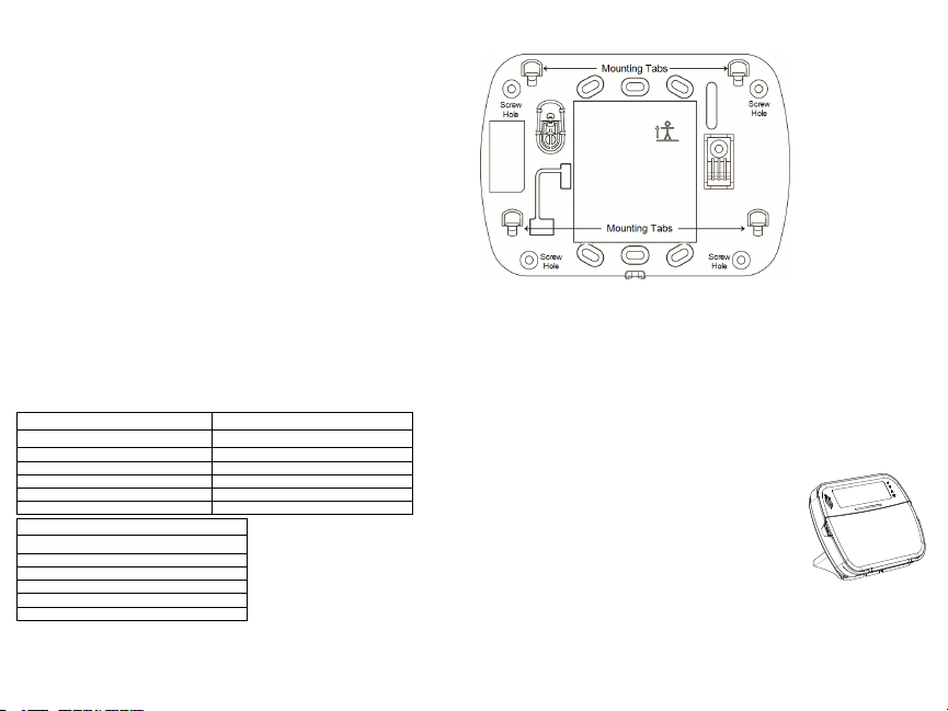
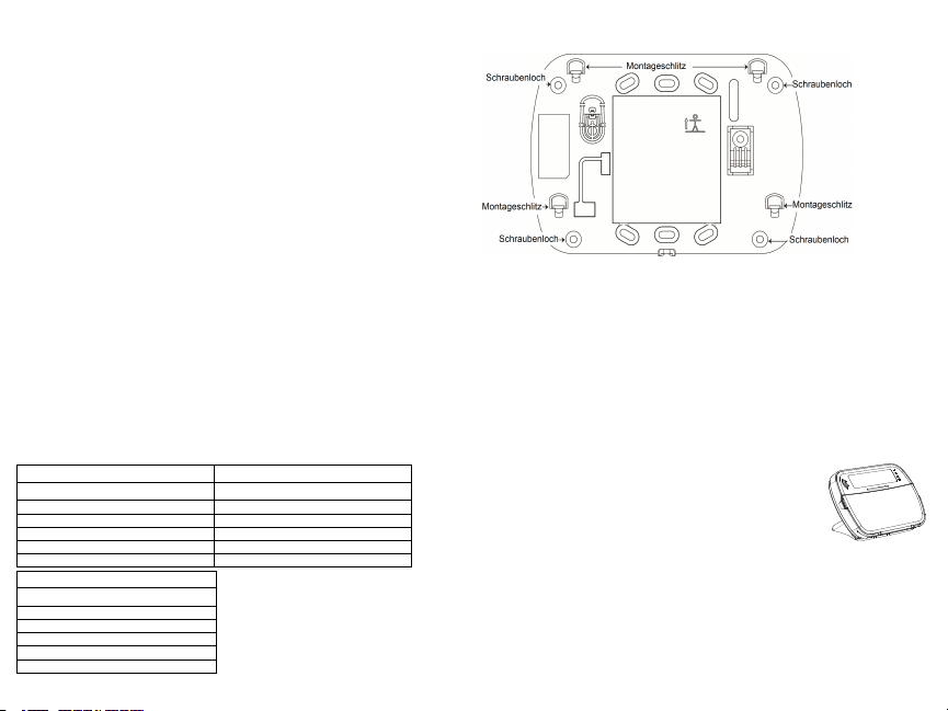
WallMounting Plate
1. Locate t he s crew holes (4) at each corner of the mountingplate.
2. Use the four screws provided to affix the mountingplate to the wall; ensure the mounting tabs are
facing you (see following diagram). If the keypad is to be mounted on drywall, use plas tic anchors.
3. Once the batteries are install ed, align the four mountings lots in the HS2LCDWF housing wi th the
fourmounting tabs protruding from the mounting plate.
4. Firmly but carefully s nap the keypad down onto the mounting plate.
Desk Stand - HS2LCDWFDMK(Optional)
1. Insert t he four rubber feet (found in the hardware pack) into the indentations provided in the bottom
of the desk stand.
2. Place the desk stand on a secure, uncluttered surface.
3. Align t he four mounting slots in the HS2LCDWF housing wi th t he four
mounting tabs protruding from the desk stand.
4. Slide the keypad into place. Firmly but carefully snap the keypad down
onto the desk s tand.
5. To fast en the keypad securely onto the desk stand, locate the hole in
the center of the bottom of the desk stand. Using the s crews provided,
screw the keypadt o t he desk st and.
Apply Battery Power
WARNING: If a low battery t rouble signal is noted,the unit will operate
for a duration of no longer than 30 days. When a low battery trouble signal is noted, the batteries must
be replaced to ensure proper operation of the unit.
1. If required, s lide the keypad up and out from t he mounting plate/desk stand (removing the screws
first if required). The bay for the four AA batteries is open and vis ible at the back of t he keypad.
2. Insert t he batteries as directed on the back of the keypad. Ensure t he correct polarity is observed.
3. Replace the keypad on the mounting plate/des k s tand.
CAUTION: Do not mix old batteries with new ones.
Apply AC Power
CAUTION: The s ocket-outlet in which the
direct plug-in adaptor is inserted must be
close to the keypad, easily access ible, and
have unobstructed access . The plug of the
adaptor serves as a means of disconnection
from the supply mains.
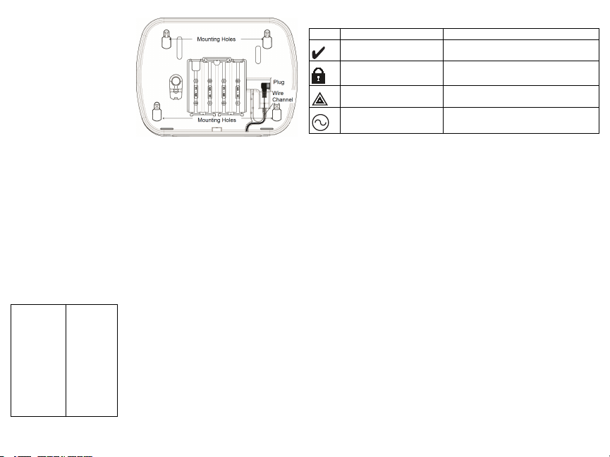
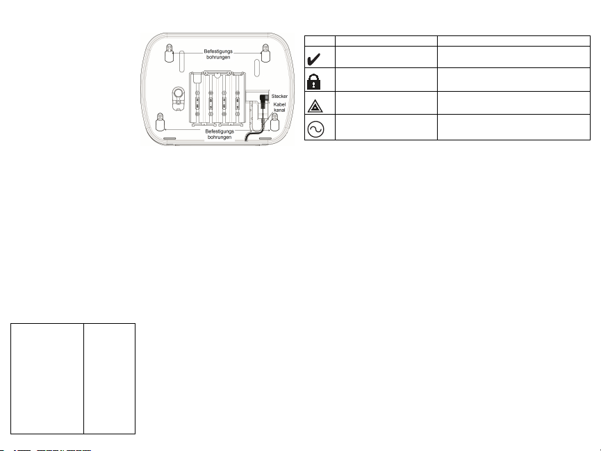
1. Slide the keypad up and out from the
mounting plate/desk sta nd.
2. Locate t he power adaptor jack at the
back of the keypad housing.
3. Place the adaptor plug in the housing
indentation, perpendicular to the keypad.
Insert t he adaptor plugfirmly into the j ack.
4. Pivot t he adaptor plugdownwards so that
it fits flush with the housing. Guide t he A C
wire along the channel provided in the keypad housing; the w ire will extend through the bottom of the
housing.
5. Replace the keypad on the mounting plate/des k s tand (in the latter case, a further channel is
provided in the bottom of the desk s tand. Guide t he A C wi re along this channel; the wi re will extend
through an opening in the back of t he s tand).
6. Plug the adaptor into a wall outlet.
Only use the power adaptor (9.0VDC, @1.25A, 2.25W, l imited power supply for models: HK -XX11U09N (UL) and H K-XX11-U09NC (ULC).
Program the Keypad
There are several programming options available for the keypad(see the following table). Programming
the keypad is similar t o programming the rest of the s ystem. The installer menu i s a text driven flow.
For i nformation on programming the rest of your s ecurity s ystem, refer t o your s ystem’s install ation
manual.
1. Press [*][8][Installer Code].
2. Use the [<][>] keys to navigate t hrough the menus or jump directly t o a s pecific section by entering
the section number.
Language Programming
To enter language programming, enter [000]>[000], then enter the two-digit number that corresponds to
the language desi red:
01 = English (def)
02 = Spanish
03 = Portuguese
04 = French
05 = Italian
06 = Dutch
07 = Polish
08 = Czech
09 = Finnish
10 = German
11 = Swedish
12 = Norwegian
13 = Danish
14 = Hebrew
15 = Greek
16 = Turkish
17 = Future Use
18 = Croatian
19 = Hungarian
20 = Romanian
21 = Russian
22 = Bulgarian
23 = Latvian
24 = Lithuanian
25 = Ukrainian
26 = Slovakian
27 = Serbian
28 = Estonian
29 = Slovenian
Keypad Symbols
Symbol Description
Ready Light (Green) If R eady light is ON, the s ystem is ready to arm.
ArmedLight (Red)
System Trouble (Yellow)
If Armed light is ON/Flashing, the system has been
armeds uccessfully.
ON - Indicates that a system trouble is active..
Flashing - Keypad low battery.
AC (Green) ON - Indicates that AC is present at the keypad
Enroll HSM2HOST
The HS M2HOST wireles s transceiver or H S2LCDRF/HS2ICNRF keypad must be enrolled onto the
alarm panel before any w ireless devices can be enrolled. When the alarm s ystem is powered up for the
first time, the first keypad or t he H SM2HOST (if using a wireless keypadas the first keypad) can be
enrolled. To do this:
1. Once the HS M2HOST is wired to the al arm panel and power has been applied, power up a wi reless keypad.
2. Press any button on the keypad to enroll it on t he H SM2HOST. The H SM2HOST is thena utomatically enrolled on the alarm panel.
Enroll Keypad
1. Press [*][8][Installer Code] and then [804][000].
2. When prompted, ei ther act ivate the device to enroll immediately or enter a device serial number. Do
the latter to pre-enroll devices then enroll them later at the customer s ite.
3. Use the [<][>] keys or enter the corresponding number t o s elect an option.
4. Scroll through the available selections and enter a number or enter text as appropriate.
5. Press [*] to acce pt and move to the next option.
6. Once all options are configured, the system prompts you to enroll the next device.
7. Repeat this process until all wi reless devices are enrolled.
For U L/ULC Resi dential Fire applications, HS2LCDWF9, HS2LCDWFP9, HS2LCDWFPV9
keypads must be s et up for 200 s econds wireless supervision, by enabling toggle option 4 (200s Fire
Supv), in section [804][810].
Delete Keypad
1. Press [*][8][Installer Code] and then [804][905].
2. Use the [<][>] keys to select the keypad or press [#] to exit.
3. Press [*] to delete. The screen will read “Keypad deleted”.
Program Labels
Use this section to ass ign a meaningful name (e.g., Front D oor, Hal lway, etc.) to each zone.
1. Press [*][8] [Installer code].
2. Press [*] and use the [<][>] keys to scroll to Zone Labels and press [*] again. The first zone is displayed. Al ternatively, enter [000][001].
3. Scroll to t he zone label to be programmed and press [*] or enter the zone number (e.g., 001 for zone
label 1).
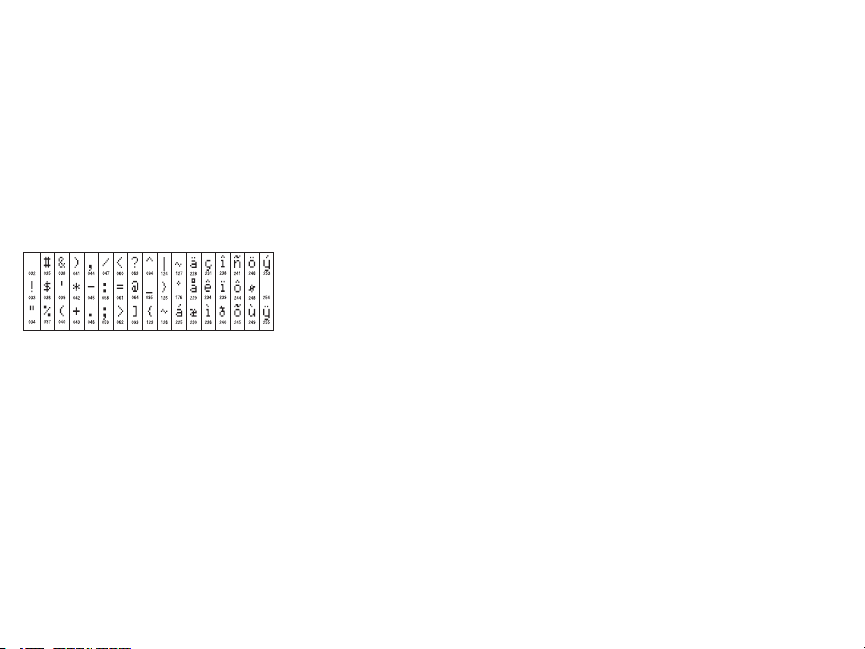
4. Scroll to t he desi red character’s location us ing the [<][>] keys.
5. Enter the number of the corresponding character group until the des ired character is displayed (see
the followingt able).Example: Pres s the “2” key 3 times to enter t he l etter “F”. P ress the “2” key 4
times to enter the number “2”.
[1] - A, B, C, 1 [4] - J , K, L, 4 [7] - S, T, U, 7 [0] - S pace
[2] - D, E, F, 2 [5] - M, N, O, 5 [8] - V, W, X, 8 [*] - Select
[3] - G, H, I, 3 [6] - P, Q, R, 6 [9] - Y , Z, 9,0 [#] - Es cape
6. To s ave t he l abel, press [#], and the label is automatically saved. To delete a character, use the [<]
[>] keys to move the cursor under the character, then press [0]. If any key other than [<] or [>] i s
pressed before [0], the cursor moves one space to the right and deletes that character.
ASCIICharacter
Label Library
The Label Library is a database of w ords commonly used when programming labels. Individual w ords
can be combined as needed (e.g., Front + Door). Each line of the display s upports a maximum of 14
characters. If a word will not fit on a l ine, scroll right until the cursor appears at the first character of
the second line then add the word.
To program a custom l abel using the Label Library:
1. Press [*][8][Installer Code][000][001] (to program the label for zone 01).
2. Press [*] to open t he menu.
3. Press [*] again to selec t the “Word Entry” option.
4. Enter the 3-digit number corresponding to a word (see Words Library) or use the s croll keys [<][>]
to view words i n the li brary.
5. Press [*] to s elect the word.
6. To add another w ord, repeat the previous procedure from step 2.
7. To add a space, press the right s croll key [>].
8. To clear characters, s elect “Clear to End” or “Clear Display” from the “Select O ptions” menu.
9. To s ave t he l abel, press [#], and the label is automatically saved.
Broadcast LCD Labels
If more than one LCD keypad is present on the sys tem, labels programmed at one keypad wi ll be broadcast to all other LCD keypads right after t he change is confirmed.
Voice Prompt/Voice Chime
Voice Prompt Control(for wireless keypads only)
Menu: [*][6][access code] > Voice Prompt
This functioni s used to change t he volume level of keypad voice prompts, for example, “User arming
in progress.” The voice prompt s peaks t he zone labels programmed for zone openings/closings. Us e
the scroll keys [<][>] to increase or decrease the volume from levels 0-10. Selecting 00 turns off
keypad voice prompts.
Voice Chime Control
Menu: [*][6][access code] > Chime Control
This functioni s used to change t he keypad voice chime volume level. Use the scroll keys [<][>] t o
increase or decrease the volume from levels 0-10. Selecti ng 00 turns off voice chime.
Change Brightness/Contrast/Buzzer
LCD Keypads
1. Press [*][6][Master Code].
2. Use the [<][>] keys to scroll to either Bright Control, Contrast Control, Buzzer Control.
3. Press [*] to s elect the set ting you wa nt t o adjust.
4. (a) Brightness/LED Bar Control: There are 15 back lighting levels . Use the [<][>] keys to scroll to
the desired level. Changing this level adjusts the LED bar accordingly.
b) Contrast Control: There are 15 different display contrast levels . Us e the [<][>] keys to scroll to the
desired contrast level.
c) Buzzer Control: There are 15 different buzzer control l evels. Us e the [<][>] keys to scroll to the
desired buzzer level.
Proximity Tags (HS2LCDWFP, HS2LCDWFPV only)
The proximity tag can be used to perform any keypad function that would normally require a user
access code. The tag is to be presented t o the center left face of the keypad. While the keypad is running off AC, the transceiver is always on to detect any prox tag approaching. While the keypad is running on battery and in sleep mode, the user can press any key to wake t he keypad, t hen present the
proxt ag.
Enroll Proximity Tags
Enrolling a tag on one keypad will enroll it automatically to al l HS2LCDWFP or HS 2LCDWFPV
keypads enrolled on the syst em. Master code (code 1) cannot have a prox tag as signed t o it .
1. Press [*][5][Master Code].
2. Use the [<][>] keys to scroll to the applicable user and press [*].
3. Use the [<][>] keys to scroll to Prox Tag and press [*]. The screen dis plays: “Present Tag”.
4. Pass the enrolled tag near t he tag reader on the keypad. A proxtag can only be as signed to one use r
at a time.
5. If enrollment is successful, acknowledgment beeps wil l sound and the keypad LCD will read ‘Tag
Enrolled Successfully’. If enrollment is unsuccessful, an error tone w ill sound and the keypad wil l
read ‘Invalid Tag Not Enrolled’. If the tag has been enrolled previously, an error t one wil l sound and
the keypad wil l read ‘Duplicate Tag Not Enrolled’.
Delete Proximity Tags
Delete the prox tags from the system when they are lost or no longer needed.
1. Press [*][5][Master Code].
2. The keypad displays the user number and includes t he le tter ‘T’ if a prox tag is programmed.
3. Use the [<][>] keys to locate the desired us er and press [*]. Scroll to P rox Tag and press [*].
4. The keypad reads ‘Press [*] To Delete Tag’. After pressing [*], the message ‘Tag D eleted Successfully’ appears.
Keypad Function Key Programming
To program a functionkey:
1. Press [*][8][Installer Code].
2. Enter [861] for keypad programming. Section [860] is read-only and shows the slot number of the
keypad being accessed.
3. Enter [001]-[005] for function keys 1-5.
4. Enter a 2-digit number to ass ign a function key operation - [00]-[68]. See the following tables.
5. Continue from s tep 3 until all function keys are programmed.
6. Press [#] twice to exit Installer Programming.

[001]-[005] FunctionKey Assignments
Function
Section
[001] 1 00-68 03 Stay Arm |____|____|
[002] 2 00-68 04 Away Arm |____|____|
[003] 3 00-68 06 Chime ON/O FF |____|____|
[004] 4 00-68 22 Comm O utput 2 |____|____|
[005] 5 00-68 16 Quick Exit |____|____|
Keypad FunctionKeys
Pleas e see your system inst allation manual for more details on the function key options:
[00]- Null [17]- Arm Interior [39]-Trouble Di splay
[02]- Instant Stay Arm [21] - Command Output 1 [40]- Al arm Memory
[03]- St ay A rm [22]- CommandO utput 2 [61] - Partition Select 1
[04]- Aw ay A rm [23]- CommandO utput 3 [62] - Partition Select 2
[05]- [*][9] No-EntryA rm [24] - Command Output 4 [63] - Partiti on Select 3
[06]- Chime O N/OF F [29]- Bypass Group Recall [64] - Partit ion Select 4
[07]- Sys tem Test [31] - Local PGM Activate [65]- Pa rtition S elect 5
[09]- Ni ght Arm [32]- Bypass Mode [66]- P artition Select 6
[12]- Gl obal St ay A rm [33] - Bypass Recall [67]- Pa rtition S elect 7
[13]- Gl obal Away Arm [34]- Us er Programming [68] - Partition Select 8
[14]- Gl obal Dis arming [35]- Us er Functions
[16]- Quick Exit [37] -Time and D ate Program
Keypad Programming
Press [*][8][Installer Code]
[860] Keypad Slot Number
This is not for programming; the tw o-digit slot number is displayed for informational purposes only.
[861]-[876] Keypad ProgrammingSections
Sections [861]-[876] apply to keypads lot numbers 1-16accordingly. After s electing the appropriate
keypad s ection number, the following programming options are available:
[000] Address of Partition
On selecting [000], a 2-digit entry is required to assign the keypad to a partition. Valid entries are 01-
08. The default i s 01. NOTE:The HS2LCDWF keypad cannot be ass igned as a global keypad.
Key
Button
Valid
Range
Default Function
[001]-[005] FunctionKey 1- 5 Assignment
[011] Keypad Input/Output Programming
Zone or P GM Number 000 |______|______|______|
[012] Local PGM Output Pulse ActivationTime
|_____|_____| Minutes (00-99); |_____|_____| Seconds (00-99)
[021] First Keypad Options
Default Opt. ON OFF
ON |______| 1 Fire Key Enabled Fire Key Disabled
ON |______| 2 Medical Key Enabled Medical Key D isabled
ON |______| 3 Panic Key Enabled Panic K ey D isabled
ON |______| 4
OFF |______| 5 For Future Use For Future Use
OFF |______| 6 For Future Use For Future Use
OFF |______| 7 For Future Use For Future Use
OFF |______| 8 For Future Use For Future Use
NOTE: For EN50131-1/EN50131-3 compliant systems, section [021]: options 1 and 2 shall be OFF.
Display Access Code When
Programming
Display X’s When Programming
Access Codes
[022] Second Keypad Options
Default O pt. ON OFF
ON |______| 1 Local Clock D isplay ON Local Clock Display OFF
OFF |______| 2 Local Clock Displays 24-hr Time Local Clock Displays AM/ PM
ON |______| 3 A uto Al arm S croll O N Auto Alarm Scroll OFF
OFF |______| 4 For Future Us e For F uture Us e
OFF |______| 5 Power LED Enabled Power LED Disabled
ON |______| 6 P ower LED A C P resent ON P ower LED AC Present OF F
ON |______| 7 A larms Dis played While Armed Alarms Not Displayed While Armed
OFF |______| 8 Auto-Scroll O pen Zones ON Auto-Scroll Open Zones OFF
[023] ThirdKeypad Options
Default O pt ON OFF
OFF |______| 1 Armed LED On i n S leep Mode Armed LED Off in Sleep Mode
ON |______| 2 Keypad S tatus Shows Stay Arm Keypad Status Shows Stay/Aw ay Arm
OFF |______| 7 Temperature Dis play Enabled Temperature D isplay Disabled
Programming options indicated in GREY are required for systems compliant with EN50131-1 and
EN50131-3s tandards. Section [023]: 1=OF F
[030] LCD Message
|_____|_____|_____|_____|_____|_____|_____|_____|_____|_____|_____|_____|_____|_____|_____|_____|
NOTE: Clock display (Section [022], Option 1) must be enabled.
[031] DownloadedLCD Message Duration
Default: 000 |______|______|______| (Valid entries are 000-255), 000=Unlimited Mess age D isplay.
This number represents the number of times the downloaded message must be cl eared before it is permanently removed. Press any key to delete message.
[041] IndoorTemperature Zone Assignment
Default: 000 |______|______|______| (Valid entries are 000-128)
[042] Outdoor Temperature Zone Assignment
Default: 000 |______|______|______| (Valid entries are 000-128)
[101]-[228] Door Chime for Zones 1-128
The keypad can be programmed to make up to four different chime s ounds for individual zones. (e.g.,
for Zone 1, enter Section [101], for Zone 2 enter S ection [102]). Default: 01 |_____|_____|

Option
01 6 beeps
02 Bing-Bing tone
03 Ding-Dong tone
04 Alarm tone (4 s econd duration)
05 Zone Name
[991] Reset Keypad Programming to Factory Defaults
1. Press [*][8][Installer Code].
2. Enter [991].
3. Use the [<][>] keys to scroll to the applicable keypad.
4. Press [*] to s elect the keypad.
5. Re-enter [Installe r Code].
6. Press [*] to res et the selected keypad to factory defaults.

WordLibrary
Item # Text Item # Text Item# Text Item # Text Item# Text Item# Text Item # Text
001 Aborted 037 Closed 073 Feature 109 Library 145 Pool 181 Tamper 217 N
002 AC 038 C loset 074 Fence 110 Light 146 Porch 182 Temperature 218 O
003 Access 039 Closing 075 Fire 111 Lights 147 Power 183 Test 219 P
004 Active 040 C ode 076 First 112 Living 148 Press 184 Time 220 Q
005 Activity 041 Communicator 077 Floor 113 Load 149 Program 185 To 221 R
006 Alarm 042 Computer 078 Force 114 Loading 150 Progress 186 Touchpad 222 S
007 All 043 C ontrol 079 Foyer 115 Low 151 Quiet 187 Trouble 223 T
008 AM 044 Date 080 Freeze 116 Lower 152 Rear 188 Unbypass 224 U
009 Area 045 Daughter’s 081 Front 117 Main 153 R eceiver 189 Unit 225 V
010 Arm 046 Degrees 082 Furnace 118 Master 154 R eport 190 Up 226 W
011 Armed 047 Delay 083 Gallery 119 Mat 155 RF 191 West 227 X
012 Arming 048 Den 084 Garage 120 Medical 156 R ight 192 W indow 228 Y
013 Attic 049 Desk 085 Gas 121 Memory 157 Room 193 Zone 229 Z
014 Auxiliary 050 Detector 086 Glass 122 Menu 158 Safe 194 0 230 Space
015 Away 051 Dining 087 Goodbye 123 Monoxide 159 Saver 195 1 231 ,
016 B aby 052 Dis armed 088 Gym 124 Mother’s 160 Schedule 196 2 232 017 B ack 053 Door 089 Hallway 125 Motion 161 Screen 197 3 233 _ (Underscore)
018 B ar 054 Down 090 Heat 126 No 162 Second 198 4 234 *
019 B asement 055 Download 091 Hello 127 North 163 Sensor 199 5 235 #
020 B athroom 056 Downstairs 092 Help 128 Not 164 Service 200 6 236 :
021 B attery 057 Drawer 093 High 129 Now 165 Shed 201 7 237 /
022 B edroom 058 Driveway 094 Home 130 Number 166 Shock 202 8 238 ?
023 B onus 059 Duct 095 House 131 Off 167 Shop 203 9
024 B ottom 060 Duress 096 In 132 Office 168 Side 204 A
025 B reezeway 061 East 097 Install 133 OK 169 Siren 205 B
026 B uilding 062 Energy 098 Interior 134 On 170 Sliding 206 C
027 B us 063 Enter 099 Intrusion 135 Open 171 Smoke 207 D
028 B ypass 064 Entry 100 Invalid 136 Opening 172 Son’s 208 E
029 B ypassed 065 Error 101 Is 137 Panic 173 Sound 209 F
030 C abinet 066 Exercise 102 Key 138 Partition 174 South 210 G
031 C amera 067 Exit 103 Kids 139 Patio 175 Special 211 H
032 C anceled 068 Exterior 104 Kitchen 140 Pet 176 Stairs 212 I
033 C ar 069 Factory 105 Latchkey 141 Phone 177 Stay 213 J
034 C arbon 070 Failure 106 Laundry 142 Please 178 Sun 214 K
035 C entral 071 Family 107 Left 143 PM 179 Supervisory 215 L
036 C hime 072 Father’s 108 Level 144 Police 180 System 216 M

Limited Warranty
+HUHE\'6& GHFODUHV WKDW WKLV GHYLFH LVLQ FRPSOLDQFHZLWK WKHHVVHQWLDO
UHTXLUHPHQWVDQGRWKHUUHOHYDQWSURYLVLRQVRI'LUHFWLYH(&
7KH FRPSOHWH577( 'HFODUDWLRQ RI&RQIRUPLW\ FDQEHIRXQGDW
KWWSZZZGVFFRPOLVWLQJVBLQGH[DVS[
&=('6&MDNRY¿UREFHSURKODģXMHŀH WHQWRY¿UREHNMHY VRXODGXVHYģHPL
UHOHYDQWQ¯PLSRŀDGDYN\VPÝUQLFH(&
'$1'6&HUNO¨UHUKHUYHGDWGHQQHNRPSRQHQWHQRYHUKROGHUDOOHYLNWLJHNUDYVDPW
DQGUHEHVWHPPHOVHUJLWWLGLUHNWLY(&
'87+LHUELMYHUNODDUW'6&GDWGLWWRHVWHOLQRYHUHHQVWHPPLQJLVPHWGHHLVHQHQ
EHSDOLQJHQYDQULFKWOLMQ(&
),1'6&YDNXXWWDDODLWWHHQW¦\WW¦Y¦QGLUHNWLLYLQ(&ROHQQDLVHWYDDWLPXNVHW
)5(3DUODSU«VHQWH'6&G«FODUHTXHFHGLVSRVLWLIHVWFRQIRUPHDX[H[LJHQFHV
HVVHQWLHOOHVHWDXWUHVVWLSXODWLRQVSHUWLQHQWHVGHOD'LUHFWLYH(&
*(5+LHUGXUFKHUNO¦UW'6&GD¡GLHVHV*HU¦WGHQHUIRUGHUOLFKHQ%HGLQJXQJHQXQG
9RUUDXVHW]XQJHQGHU5LFKWOLQLH(&HQWVSULFKW
*5(˂˜˞˱ˬ˲˭˞ˮ˹˪˱ˬ˯ˤ'6&ˡˤ˨˻˪ˢ˦˹˱˦˞˲˱˛ˤ˰˲˰˧ˢ˲˛ˢ˜˪˞˦˰˺˩˳˶˪ˤ˩ˢ˱˦˯
ˬ˲˰˦˻ˡˤ˯˞˭˞˦˱˛˰ˢ˦˯˧˞˦˩ˢ˹˨ˢ˯˱˦˯˙˨˨ˢ˯˰˴ˢ˱˦˧˚˯˞˪˞˳ˬˮ˚˯˱ˤ˯ˍˡˤˠ˜˞˯(&
,7$&RQODSUHVHQWHOD'LJLWDO6HFXULW\&RQWUROVGLFKLDUDFKHTXHVWRSURGRWWRª
FRQIRUPHDLUHTXLVLWLHVVHQ]LDOLHGDOWUHGLVSRVL]LRQLULOHYDQWLUHODWLYHDOOD'LUHWWLYD
&(
125'6&HUNO¨UHUDWGHQQHHQKHWHQHULVDPVYDUPHGGHJUXQQOHJJHQGHNUDYRJ
ºYULJHUHOHYDQWHNUDYLGLUHNWLY()
32/'6&RĝZLDGF]DľHXU]ÇG]HQLHMHVWZ]JRGQRĝFL]]DVDGQLF]\PLZ\PDJDQLDPL
RUD]SR]RVWDĄ\PLVWRVRZQ\PLSRVWDQRZLHQLDPL'\UHNW\Z\:(
3253RUHVWHPHLRD'6&GHFODUDTXHHVWHHTXLSDPHQWRHVW£HPFRQIRUPLGDGH
FRPRV UHTXLVLWRVHVVHQFLDLVH RXWUDVGHWHUPLQD©·HVUHOHYDQWHVGD 'LUHFWLYD
(&
63$3RUODSUHVHQWH'6&GHFODUDTXHHVWHHTXLSRHVW£HQFRQIRUPLGDGFRQORV
UHTXLVLWRVHVHQFLDOHV\RWURVUHTXLVLWRVUHOHYDQWHVGHOD'LUHFWLYD(&
6:('6&EHNU¦IWDUK¦UPHGDWWGHQQDDSSDUDWXSSI\OOHUGHY¦VHQWOLJDNUDYHQRFK
DQGUDUHOHYDQWDEHVW¦PPHOVHUL'LUHNWLYHW(&
DigitalSecurityControls (DSC)warrants thatfora periodof 12monthsfrom thedate ofpurchase,the
productshallbefreeofdefects inm aterialsandworkmanshipundernormal useandthatinfulfilmentof
anybreach ofsuch warranty,DSC shall,at its option, repairorreplace thedefectiveequipmentupon
returnoftheequipmenttoits repairdepot.T hiswarrantyappliesonlyto defectsinpartsandworkmanship
andnotto damageincurredinshippingorhandling,or damageduetocausesbeyondthecontrolofDSC
suchaslightning,excessivevoltage,m echanicalshock,waterdamage,ordamagearisingoutofabuse,
alterationorimproperapplicationof theequipment.Theforegoingwarrantyshallapplyonlyto theoriginal
buyer,andis andshall be inlieu ofanyand allotherwarranties,whetherexpressed orimpliedandofall
otherobligationsor liabilitiesonthepartofDSC. DigitalSecurityControlsneitherassumesresponsibility
for,norauthorizesanyotherpersonpurportingtoact on its behalftomodifyorto changethiswarranty,nor
toassumeforitanyotherwarrantyor liabilityconcerning thisproduct.In noeventshallDSC beliablefor
anydirect,indirectorconsequentialdamages,lossof anticipatedprofits,lossof time oranyotherlosses
incurredbythe buyerin connectionwiththe purchase,installationoroperation orfailureof thisproduct.
WARNING: DSC recommends that the entiresystem be completely tested on a regular basis.
However,despite frequenttesting, anddueto, butnot lim ited to,criminal tamperingor electrical disruption,it ispossiblefor this product tofail to perform as expected.Important Information: Changes/modificationsnotexpresslyapprovedbyDSC couldvoidtheuser’sauthoritytooperatethisequipment.
IMPORTANT - READCAREF ULLY: DSCSoftwarepurchasedwith orwithoutProductsand Componentsis copyrightedandis purchasedunderthefollowinglicenseterms:This End-UserLicenseAgreement(“EULA”)is alegal agreement betweenYou (thecompany,individual or entity whoacquiredthe
Softwareandany relatedHardware) andDigitalS ecurity Controls,a divisionofT yco SafetyP roducts
CanadaLtd.(“DSC”), themanufacturerof theintegratedsecurity systemsandthe developerofthe softwareandanyrelatedproductsorcomponents(“HARDWARE”)whichYouacquired.If theDSCsoftware
product (“SOFTWARE PRODUCT” or “SOFTWARE”) is intended to be accompanied by
HARDWARE,andisNOT accompaniedby newHARDWARE, Youm aynotuse,copyori nstallthe
SOFTWARE PRODUCT. T heSOFTWARE PRODUCT includescomputer software, andmay
includeassociatedmedia,printedmaterials,and“online”orelectronicdocumentation.
Anysoftware provided along with theSoftware Product that is associatedwith a separateend-user
licenseagreementis licensedtoYou underthetermsofthat licenseagreement.By installing,copying,
downloading,storing,accessingorotherwiseusingtheSoftwareProduct,Youagreeunconditionallyto be
boundbythe terms of thisEULA, evenif this E ULAis deemed to be am odificationof anyprevious
arrangementorcontract.IfYou donotagreetothe terms ofthisEULA, DSC isunwillingtolicensethe
SoftwareProducttoY ou,andYouhavenorighttouseit.
SOFTWARE PRODUCTLICENSE -T heSOFTWARE PRODUCT isprotectedbycopyrightlaws
andinternational copyright treaties, as well as other intellectual property laws and treaties. The
SOFTWARE PRODUCTis licensed,notsold.
1.GRANT OF LICENSEThis EULAgrantsYouthefollowingrights:
(a)SoftwareInstallation andUse- F oreachl icenseYouacquire, Y oumayhave onlyone copyof the
SOFTWARE PRODUCTinstalled.
(b)Storage/NetworkUse -T he SOFTWARE PRODUCT maynot beinstalled,accessed,displayed,
run,sharedorusedconcurrentlyonorfrom differentcomputers,includingaworkstation,terminalorother
digitalelectronic device(“Device”). In other words,if Y ouhave severalworkstations, Y ouwill haveto
acquirea licenseforeachworkstationwheretheSOFTWARE will be used.
(c)BackupCopy-Youm aym akeback-upcopiesof theSOFTWARE PRODUCT,butYoum ayonly
haveonecopyperlicenseinstalledatanygiventime. Youmay usetheback-upcopysolelyforarchival
purposes.Except as expresslyprovided in thisEULA, You m ay nototherwisem ake copiesof the
SOFTWARE PRODUCT,includingtheprintedmaterialsaccompanyingtheSOFTWARE.
2.DESCRIPTIONOF OTHER RIGHTSAND LIMITATIONS
(a)LimitationsonReverseEngineering,Decompilationand Disassembly- Youm aynotreverse engineer,decompile,ordisassembletheSOFTWARE PRODUCT,except andonlytotheextentthatsuch
activityis expresslypermittedby applicablelawnotwithstandingthislimitation.You maynotm akeany
changesormodificationsto theSoftware,withoutthewritten permissionofan officerofDSC. Youmay
notremoveanyproprietarynotices, marksorlabelsfrom the SoftwareProduct.Youshallinstitute reasonablemeasurestoensurecompliancewiththetermsandconditionsofthisE ULA.
(b)Separationof Components- TheSoftware Productis licensedasa singleproduct. Itscomponent
partsmay notbeseparatedforuseonmorethanoneHARDWARE unit.
(c)SingleINTEGRATEDPRODUCT - If Youacquiredthis SOFTWARE withHARDWARE,then
theSOFTWARE PRODUCTis licensedwiththeHARDWARE asa singleintegratedproduct.Inthis
case,theSOFTWARE PRODUCT may onlybeusedwiththeHARDWARE assetforthinthis
EULA.
(d)Rental -Youm aynotrent,leaseorlendtheSOFTWARE PRODUCT.Youm aynotmakeit availabletoothersor postit ona serverorwebsite.
(e)SoftwareProductTransfer-Youm aytransferall of YourrightsunderthisEULA onlyaspartofa permanentsale or transferof theHARDWARE, providedYou retain no copies,You transferall of the
SOFTWARE PRODUCT (includingall component parts, the m edia and printed materials, any
upgrades and this EULA), and provided the recipient agrees to the terms of this EULA. If the
SOFTWARE PRODUCT is an upgrade, any transfer must also include all prior versions of the
SOFTWARE PRODUCT.
(f)Termination-Withoutprejudiceto anyotherrights,DSC m ayterminatethisEULA ifY oufailtocomplywith the termsand conditions of this EULA. In suchevent, Y ou mustdestroy all copiesof the
SOFTWARE PRODUCTandall ofits componentparts.
(g)Trademarks-T hisEULA doesnotgrantYouanyrightsinconnectionwithanytrademarksorservice
marksofDSC orits suppliers.
3.COPYRIGHT - A ll titleandintellectual property rightsin and to theS OFTWARE PRODUCT
(includingbut not limited to anyim ages, photographs, and text incorporatedintothe SOFT WARE
PRODUCT),theaccompanying printedmaterials,and anycopiesof theSOFTWARE PRODUCT,
areownedby DSC or its suppliers. Y ou may not copy the printed materials accompanying the
SOFTWARE PRODUCT.All title andintellectualpropertyrights in andtothe contentwhichmaybe
accessedthroughuseoftheSOFT WARE PRODUCT are thepropertyof therespectivecontentowner
andmaybeprotectedbyapplicablecopyrightor otherintellectualpropertylawsandtreaties.This EULA
grantsYou norightstousesuchcontent.All rightsnotexpresslygrantedunderthisEULA arereservedby
DSCandits suppliers.
4.EXPORT RESTRICTIONS- You agreethat Youwill not exportor re-export theSOFTWARE
PRODUCT toanycountry,person,orentitysubjecttoCanadianexportrestrictions.
5.CHOICEOF LAW- This SoftwareLicenseAgreement is governedby thelawsof theProvinceof
Ontario,Canada.
6.ARBITRATION -All disputesarisingin connectionwiththisAgreementshallbe determinedbyfinal
andbindingarbitrationinaccordancewiththeArbitrationAct,andthepartiesagreetobe boundbythearbitrator’sdecision.TheplaceofarbitrationshallbeToronto,Canada,andthelanguageofthearbitrationshall
beEnglish.
7.LIMITED WARRANTY
(a)NOWARRANTY -DSC PROVIDES THE SOFTWARE “AS IS”WITHOUT WARRANTY.
DSC DOES NOT WARRANT T HAT THE S OFTWARE WILL MEET YOUR
REQUIREMENTS OR THAT OPERATION OF THE SOFTWARE WILL BE
UNINTERRUPTEDOR ERROR-FREE.
(b)CHANGES IN OPERATING ENVIRONMENT - DSC shall not be responsiblefor problems
causedbychangesin theoperatingcharacteristicsoftheHARDWARE, orforproblems intheinteraction
oftheSOFTWARE PRODUCT withnon-DSC-SOFTWARE orHARDWAREPRODUCTS.
(c)LIMITATIONOF LIABILITY; WARRANTY REFLECTS ALLOCATION OF RISK - INANY
EVENT, IF ANY STA TUTE IMPLIES WARRANTIES OR CONDITIONSNOT STATE DIN
THIS LICENSE AGREEMENT, DSC’S ENTIRE LIABILITY UNDER A NY PROVISION OF
THIS LICENSEAGREEMENT S HALLBE LIMITED TO THE GREATER OF THE AM OUNT
ACTUALLY PAID BY YOU TO LICENSE THE SOFTWARE P RODUCT AND F IVE
CANADIAN DOLLARS (CAD$5.00). BECAUSE SOME JURISDICTIONS DO NOT ALLOW
THE EXCLUSIONORLIMITATION OF LIABILITY FOR CONSEQUENTIALOR INCIDENTAL
DAMAGES, THE ABOVE LIMITATIONM AY NOT APPLY TO YOU.
(d)DISCLAIMER OF WARRANTIES - THIS WARRANTY CONTAINS THE ENTIRE
WARRANTY AND SHALL BE IN LIEU OF ANY AND ALL OTHER WARRANTIES,
WHETHER EXPRESSED OR IMPLIED (INCLUDING ALL IMPLIED WARRANTIES OF
MERCHANTABILITY ORFIT NESS FOR A PARTICULARPURPOSE)AND OF ALLOTHER
OBLIGATIONS OR LIABILITIES ON THE PART OF DSC. DSC MAKES NO OTHER
WARRANTIES.DSC NEITHER ASSUMES NOR AUTHORIZESANY OTHER PERSON
PURPORTINGTOA CT ONITS BEHALFT OM ODIFYOR TO CHANGET HISWARRANTY,
NORTO ASSUME F ORIT ANY OTHER WARRANTY OR LIABILITY CONCERNINGTHIS
SOFTWARE PRODUCT.
(e) EXCLUSIVE REM EDY AND LIMITATION OF WARRANTY - UNDER NO
CIRCUMSTANCES S HALL DSC BE LIABLE FOR ANY SPE CIAL, INCIDENTAL,
CONSEQUENTIALOR INDIRECT DAMAGES BASED UPON BREACH OF WARRANTY,
BREACHOF CONTRACT, NEGLIGENCE, STRICT LIABILITY, OR ANY OTHER LEGAL
THEORY.SUCH DAMAGES INCLUDE, BUT ARE NOT LIMITED TO,LOSS OF PROFITS,
LOSSOF THE SOFTWARE P RODUCT OR ANY A SSOCIATED E QUIPMENT,COST OF
CAPITAL,COST OF SUBSTITUT E OR REPLACEMENT E QUIPMENT,F ACILITIES OR
SERVICES, DOWN TIME, PURCHASERS T IME, THE CLAIMS OF T HIRD PARTIES,
INCLUDINGCUSTOMERS,A NDINJURYT OP ROPERTY.WARNING:DSC recommendsthat
theentiresystem becompletelytestedona regular basis.However,despitefrequenttesting,anddueto,
butnot lim ited to, criminal tampering or electrical disruption, it is possible for this SOFTWARE
PRODUCT tofail toperform asexpected.
FCC Compl iance Statement
Caution:Changesormodifications notexpresslyapproved by DigitalSecurityControls couldvoidyour
authoritytousethisequipment.
Thisequipmentgeneratesandusesradiofrequencyenergyandif notinstalledandusedproperly,in strict
accordancewiththemanufacturer’sinstructions,m aycauseinterferencetoradioandtelevisionreception.
Ithasbeentypetestedandfoundtocomplywith thelimits forClassB devicein accordancewiththespecificationsin Subpart“B”of Part15of FCC Rules,whicharedesigned toprovidereasonableprotection
againstsuchinterference inanyresidential installation.However,there is no guaranteethatinterference
will notoccur ina particular installation.If this equipmentdoes causeinterferenceto televisionorradio
reception,whichcanbedetermined by turningtheequipmentoff andon,theuser is encouragedtotryto
correcttheinterferencebyone ormoreofthe followingmeasures:(i)Re-orient thereceivingantenna;(ii)
increasetheseparationbetweentheequipmentandreceiver; (iii)connecttheequipmentintoanoutleton
acircuitdifferent fromthatto whichthereceiveris connected.If necessary,theuser shouldconsultthe
dealeroranexperiencedradio/televisiontechnicianforadditionalsuggestions.Theusermay findthefollowingbookletpreparedbytheFCC helpful: “Howto IdentifyandResolveRadio/TelevisionInterference
Problems”.T his booklet is available from the U.S. Government PrintingOffice,Washington, D.C.
20402,Stock# 004-000-00345-4.
ThisClassB digitalapparatuscomplieswithCanadianICES-003.Cetappareilnumériquedela classe
B estconforme àla normeNMB -003du Canada.IC:160A-HS2LCDWF Theterm ICbeforetheradio
certificationnumbersignifiesthattheIndustryCanadatechnicalspecificationsweremet.
Thisinstallationsheetappliestom odels:HS2LCDWF, HS2LCDWFP, andHS2LCDWFPV.
TheModelHS2LCDWF,HS2LCDWFP, andHS2LCDWFPVkeypadshave beencertifiedby Teleficationaccording toEN50131-1:2006+ A1:2009,EN50131-3:2009for Grade2, ClassII. EN50131-1
Grade2/ClassII.
CAUTION:Donotdispose ofthewaste batteryas unsorted municipalwaste.Consult yourlocalrules
and/orlawsregardingrecyclingofthisbattery.
Theuse of external power adapter is optional and it has not been investigated by Telefication for
EN50131certifiedinstallations.
ForINCERT certifiedapplicationsthewirelesskeypads havebeenevaluatedundertherequirementsof
T014A usingpowersupplytypeC.
©2014TycoSecurityProducts.All RightsReserved.Toronto,Canada• www.dsc.com
TechSupport:1-800-387-3630(Canada,US),905-760-3000
Einleitung
Diese Instal lationsanleitung muss zusammen mit der Installati onsanleitung der Alarmzentrale benutzt
werden, an welcher das G erät angeschlossen w erden soll. D ie Bedienungsanleitung muss dem Benutzer übergeben werden. Da s Funk-Bedienteil H S2LCDWF ist kompatibel mit den drahtlosen Sende/Empfangsgeräten HSM2HOST und HS2LCDRF.
Technische Daten
l Temperaturbereich: -10°C bis +55°C (14°F bis 131°F) UL/ULC: 0°C bis + 49°C (32°F bis
120°F)
l Luftfeuchtigkeit (max.): 93 % relative Luftfeuchtigkeit, nicht kondensierend
l Schutzklasse Kunsts toffgehäuse: IP30, IK04
l Netzteil A usgangsspannung: 9,0 V, 1,25 A. Modelle - U SA/Lateinamerika: HK-XX11-U09N
(UL), Kanada: H K-XX11- U09NC (ULC), EU: HK -XX11- U09EU, UK: HK- XX11U09NGB, AUS/ NZ, China: HK -XX11-U09NAU le istungsbegrenzte Netzteile nach Maßgabe
der zuständigen Behörde.
l Beschränkungen bestehen für UL-Installationen.
l Dieses Produkt darf nicht an ei ne S teckdose angeschlossen werden, die mit einem Schalte r
ein oder aus geschaltet w erden kann.
l Batterie. 4 AA , 1,5 V, Energizer Alkali für privaten Gebrauch (E91)
l Anzeige Batterie schwach: 4,5 V
l HS2LCDWF Stromaufnahme: 30 mA (min.)/105 mA (max.)
l Wandmontage-S abotagevorrichtung (verbunden, wenn entsprechend UL i n gewerblichen
Anwendungen verwendet)
l 5 programmierbare Funktionstast en
l Betriebsbereit (grüne LED), Scharfgeschaltet (rote LED), Störung/Funk-Blockierung (rote/-
gelbe LED), Netzs pannung (grüne LED)
l Frequenz: 433MHz (Brasilien, China, Ös terreich (CE), Neuseeland (NA), Südafrika
(ICASA), MEA, Indien (WPC)
l Frequenz: 868MHz (EN + Lokal, MEA (CE))
l Frequenz: 912 - 919MHz (NA/ LATAM, Argentinien)
l Abmessungen (LxBxT): 168mm x 122mm x 25 mm
l Gewicht: 370g (mit Batterien)
HINWEIS: Für gewerbliche Anlagen entsprechendU L, müssen die Sabotagekontakte aktiviert se in.
Auspacken
Das HS 2LCDWF-Bedienfeld ist in drei Konfigurationen erhältlich. Das Bedienteil enthält patentierte
Technologien für den Transponder.
HS2LCDWF - W andmontage HS2LCDW FP - Nähe
1 HS2LCDWF W andhalterung 1 HS2LCDWF W andhalterung
1 Installationsanleitung 1 Installationsanleitung
1 Aufkleber in derTür des Bedienteils 1Aufkleber in der Tür des Bedienteils
4 AA Batterien 4 AA Batterien
1 PackungB efestigungsmaterialien 1 Packung Befestigungsmaterialien
HS2LCDWFPV - Transponder mit Ansage
1 HS2LCDWF W andhalterung
1 Installationsanleitung
1 Aufkleber in derTür des Bedienteils
4 AA Batterien
1 PackungB efestigungsmaterialien
1 Transponder
1 Transponder
Montieren des Bedienteil
Montieren Sie das Bedienteil i m Bereich der Zugangs- undA usgangspunkte. Nach der Wahl eines trockenen und sicheren Montageortes montieren Sie das Bedienteil wi e folgt.
Wandmontageplatte
1. Achten Sie auf die S chraublöcher (4) in den Ecken der Montageplatte.
2. Benutzen Sie die 4 mitgelieferten Schrauben zur Befestigung der Montageplatte an der Wand; achten
Sie darauf, dass die Befestigungszungen auf Sie ausgerichtet s ind (siehe nachstehende Abbildung).
Benutzen Sie Kunsts toffdübel bei Montage auf einer gemauerten Wand.
3. Nach dem Einsetze n der Batterien richten Sie die vier Montageschlitze des HS 2LCDWF-Gehäuses
mit den vier Montagestiften der Montageplatte aus.
4. Rasten Si e das Bedienteil vorsichtig, aber fest auf der Montageplatte ein.
Aufsteller- HS2LCDWFDMK(Optional)
1. Setze n Sie die vier Gummifüße (bei den Befestigungsmaterialien) in den Vertiefungen unten im Aufstell er ein.
2. Stel len Sie den Aufsteller auf einer s icheren, aufgeräumten Fläche auf.
3. Richten Sie die vier Montageeinschnitte im HS 2LCDWF-Gehäuse mit den
vier Befestigungszungena us, die auf der Montageplatte überstehen.
4. Schieben Sie das Bedienteil in P osition. Rast en Sie das Bedienteil vorsichtig, aber fest auf der Montageplatte ein.
5. Zur sicheren Befestigung des Bedienteils auf dem Aufstelle r achten Sie auf
die Bohrungmit tig unten im Aufsteller. Schrauben Sie das Bedienteil mit den
mitgelieferten Schraubena uf dem Aufsteller an.
Batteriespannung anlegen
WARNHINWEIS: Erfolgt die Anzeige Batterie s chwach, s o arbeitet das Gerät noch bis zu 30 Tagen
weiter. Erfolgt die Anzeige Batterie s chwach, s o müssen die Batterien ausgetausc ht werden, um den
korrekten Betrieb des Geräts zu gewährleis ten.
1. Fall s erforderlich, schieben Sie das Bedienteil nach oben und aus der Halterung/Tischstation (Entfernen Sie zuerst die S chrauben, wenn erforderlich). Das F ach für die vier AA Batterien i st offen und
auf der Rückseite des Bedienteils s ichtbar.
2. Setze n Sie die Batterien entsprechend den Hinweisen auf der Rückseite des Bedienteils ein. Achten
Sie auf die korrekte Polarität.
3. Setze n Sie das Bedienteil auf die Montageplatte/den Aufsteller zurück.
VORSICHT: Mischen Si e nicht erschöpfte
und frische Batterien.
Netzspannung anlegen
VORSICHT: Die S teckdose für das St eckernetzteil muss si ch dicht am Bedienteil
befinden, leicht und uneingeschränkt zugänglich sei n. Das Steckernetzteil dient dem
Abtrennendes Geräts vom Stromnetz.
1. Schieben Sie das Bedienteil nach oben und
von der Montageplatte/dem Aufstel ler ab.
2. Beachten Sie den Netzt eileingang auf der
Rückseite des Bedienteils.
3. Setze n Sie den Netzteils tecker in der Vertiefung des Gehäuses rechtwinklig zum Bedienteil ein. S etzen Sie den Netztei lstecker fest in die
Buchse ein.
4. Drehen Sie den Net zteilstecker nach unten, damit er mit dem Gehäuse abschließt. F ühren Sie das
Kabel im Bedienteil durch den Kabelkanal im G ehäuse; das Kabel tritt unten im Gehäuse aus.
5. Setze n Sie das Bedienteil auf die Montageplatte/den Aufsteller zurück (im letzteren Fall gibt es
einen weiteren Kabelkanal unten im Aufsteller. F ühren Sie das N etzkabel durch diesen Ka belkanal;
das Kabel t ritt hinten im Aufsteller aus).
6. Stecken Si e das Netztei l in eine Steckdose.
Verwenden Sie nur das Netzt eil (9,0VDC, 1,25 A, 2,25W, begrenzte St romversorgung für die
Modelle: HK-XX11-U09N (UL) und HK-XX11-U09NC (ULC).
Programmieren des Tastenfelds
Es gibt mehrere Optionen für die Programmierung des Bedienteils (s iehe folgende Tabelle). D ie Programmierung des Bedienteils ents pricht in etwa der Programmierung der anderen Geräte des Syst ems.
Das Menü des Errichters i st textbasiert. Weitere Informationen zur Programmierung des Sicherheitssys tems finden Sie in der Installationsanleitung Ihres Systems.
1. Drücken Sie [*][8][Einrichter-Code].
2. Verwenden Sie die [<][>]-Tasten, um durch die Menüs zu navigieren oder springenS ie direkt zu
einem bestimmten Abschnitt durch Eingabe der Abschnittsnummer.
Sprache programmieren
Um die Sprache zur Programmierung zu ändern, geben Sie [000]>[000] ein. Geben Sie die zwe istellige
Zahl ein, wel che der gewünschten Sprache entspricht:
01 = Englisch (Standard)
02 = Spanisch
03 = Portugiesisch
04 = Französisch
05 = Italienisch
06 = Niederländisch
07 = Polnisch
08 = Tschechisch
09 = Finnisch
10 = Deutsch
11 = Schwedisch
12 = Norwegisch
13 = Dänisch
14 = Hebräisch
15 = Griechisch
16 = Türkisch
17 = FFU
18 = Kroatisch
19 = Ungarisch
20 = Rumänisch
21 = Russisch
22 = Bulgarisch
23 = Lettisch
24 = Litauisch
25 = Ukrainisch
26 = Slowakisch
27 = Serbisch
28 = Estnisch
29 = Slowenisch
Bedienfeldsymbole
Symbol Beschreibung
Anzeige Betriebsbereit (grün)
Anzeige Scharfgeschaltet (rot)
Systemstörung(gelb)
Netzspannung (grün)
HSM2HOST registrieren
Das HS M2HOST drahtlose Sende-/Empfangsgerät oder HS2LCDRF/HS2ICNRF-Bedienteil muss an
der Alarmzentrale angemeldet werden, bevor irgendein drahtloses G erät angemeldet werden kann.
Beim ersten Einschalten des Al armsystems kann das erste Bedienteil oder der HSM2HOS T registriert werden (bei Benutzung eines Funk-Bedienteils als erstes Bedienteil). Gehen Sie w ie folgt vor:
1. Nachdem der HSM2HOST mit der Ala rmzentrale verkabelt is t undS pannung anliegt, schalten S ie
ein Funk-Bedienteil ein.
2. Drücken Sie eine beliebige Tas te auf dem Bedienteil, um es auf dem HSM2HOST zu registrieren.
Der HSM 2HOST w irddann automatisch auf der Alarmzentrale registriert.
Bedienteil registrieren
1. Geben Sie [*][8][Einrichter-Code] unddann [804][000] ein.
2. Wenn Sie dazu aufgefordert werden, aktivieren Sie entweder das Gerät zur s ofortigenRegistrierung
oder geben Sie die S eriennummer des Geräts ein. Mit let zterem nehmen Sie eine V or-Registrierung
von Geräten vor, die später beim Kunden registriert werden.
3. Verwenden Sie die [<][>]-Tasten oder geben Sie die entsprechende Zahl, um eine Option zu wählen.
4. Scrollen Si e durch die verfügbare Auswahl, geben Sie eine Zahl oder einen Text ein.
5. Drücken Sie [*] zur Bestätigung und gehen Sie zur nächsten Option.
6. Nachdem alle O ptionen konfiguriert sind, fordert Sie das Sys tem auf, das nächste Gerät zu registrieren.
7. Wiederholen Sie den Vorgang, bis all e Drahtlos-Geräte registriert s ind.
Für die UL/ULC privaten Brandmeldeanlagen HS2LCDWF9, HS2LCDWFP9, HS 2LCDWFPV9 müssen die Bedienfelder für 200 Sekunden Funküberwachung durch Aktivierung der Umschaltoption 4 (200
s F euerüberwachung) eingestellt w erden, siehe A bschnitt [804][810].
Bedienteil löschen
1. Geben Sie [*][8][Einrichter-Code] unddann [804][905] ein.
2. Verwenden Sie die [<][>]-Tasten, um das Tas tenfeld zu wählen oder drücken Sie [#], um zu beenden.
3. Drücken Sie [*] zum Löschen. Im Display wi rd „Bedienteil gelöscht“ angezeigt.
Leuchtet die Anzeige Betriebsbereit, so kann das
System scharfgeschaltet werden.
Leuchtet/blinkt die Anzeige Scharfgeschaltet, so
wurde das System erfolgreich scharfgeschaltet.
Leuchtet - Anzeige, dass eine Systemstörung vorliegt.
Blinkt - Bedienteil Batterie schwach.
Leuchtet - Anzeige, dass das B edienteil netzversorgt
ist
 Loading...