

DSC PG9944, PG8944, PG4944 Installation Instructions Manual
©2014Tyco Security Products, Toronto, Canada www.dsc.com Tech. Support: 1-800-387-3630
PG9944/8944/4944 In stallation
Instructi ons
Wi reless Ou tdo or PIR Det ector wit h C amera
Overview
The PGx944 uses eight PIR sen sors, ea ch a cting as a
Quad de tector toa ccur ately and relia bly deter mine
whethe r an a larm is justifie d. Feature s & benef its
include:
l Optimum performa nce eve n inpoor weather con-
ditions such as snow, ra in,dust, wind a nd direct
sunlight.
l Tamper protection preve ntsope ning and removal
from wa ll.
l Built-inlink qua lity indicators re duce installation
time by eliminating the need f or the installer to
physically approa ch the control pa nel.
l Microproc essor-controlled c ompensation.
l Immunity to pets weighing up to 18 Kg (40lb).
NOTE: Pet immunity fe ature ha s not bee n eva luated
to UL 639 or ULC-S306-03 d ue to the fea ture not
being addr essed in either stan dard.
CAMERA FEATURES
l Color or black & w hite images
l Auto-setup for brightness and contrast via the con-
trol panel
l Day a nd nightCMOS ca mera, with IR illumination.
This allows taking pictures in f ullda rkness
l Camera range of 12m ( 40ft); with IR illumination
10m (33ft)
l Camera operation modes:
l Post alarm – pictures a re take n after de tec-
tion by detector.
l Visual Ver ification
Device Setup
WARNI NG! To c omplyw ith FCCa nd IC RF exposur e
complianc e re quirements, the PIR detec tor should be
locate da t a dista nce of at least 2 0 cm fr om all per sons
during norma l opera tion. The ante nnas use d for this
produc tmust notbe co- located or opera ted in conjunction with a ny other a ntenna or transmitter .
NOTE: The PG Series wir eless PIR Motion de tectors
shall be installed an duse d within an environme nt that
provide sthe pollution degr ee ma x 2 and ove rvoltage s
cate gory II in NON H AZARDOUS LO CATIONS.
The e quipment is designed to be insta lled only by qua lified ser vice pe rsons.
NOTE: To ensure the continued op eration of all wire less devic es af ter pe rforming a system def ault, a
global upload of all w ireless pr ogramming via D LS is
rec ommended be fore defa ulting the system. Af ter
completing the system def ault, downloa d the wire less
progra mming.
NOTE: Back tamper switch is re quired for UL commerc ialb urglary installations.
BATTERY INSTALLATION
Initial batter y installation should be done on a flat surfac e. After inserting the batterie s, the LE D flashes for
60 sec onds and the de tector enters a 15 minute loc al
diagnostic mode.
NOTE: When manually p rogramming wir eless
devic es,if a de vice h as been powere d up for mor e
than 48 hours it cannot b e e nrolled into the syste m
until the de vice has been tampe red a nd re stored.
Whe npr ogramming the pane lusing Quick E nroll, follow the steps detailed in"En rollment."
NOTE: After restor ing a low battery trouble the system may take up to 5 minutes to clea r the tro uble.
ENROLLMENT
To quick en roll:
1. O n a keypad pr ess [*] [8] [Installer Code] [ 804]
[000].
2. Pre ss and hold the device enroll button untilthe
LED lights steady and the n release the enroll button while the LED is still lit. A confirmation message then appears on the keypad.
3. Pre ss [*] key to conf irm ID.
4. Ente r [3 digit zone #].
5. Ente r [3 digit zone type] .
6. Ente r [1 digit partition #] for a llde sired partitions
and pre ss [#]. If using an L CD keypad you ca n
scroll to the desire d partitions and press [*] to
toggle the par tition.
7. O n an LCD keypad e nter the labe l by usingw ord
library.
To pre -enroll:
1. Remotely c onfigure the unique ID number into the
system. For more informa tionse e the HSM2HOST
manual.
2. W hen on-site, pre ssthe device enr ollbutton.
NOTE: If the wirele ss device has bee n powe red for
more tha n 48 hours withoutbe ing enr olled, tampe r
and re store the device to enroll it.
PLACEMENT AND WALK TESTING
Befor e permane ntly mounting any wirele ss device ,
tempora rily mount the de vice and perf orm a Plac ement test. Pe rform a walk test o f the cove rage area at
least onc e a y ear to ensure that the detec tor is w orking corr ectly.
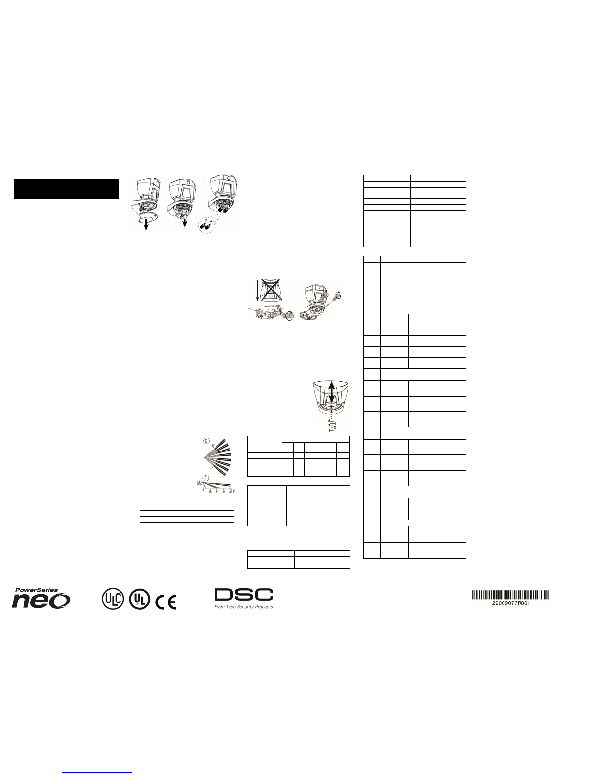
1. Ta mper the devic e by removing the c over.
2. Restore the tamper. The device
now enter s Place ment test
mode for 15 minutes.
3. Tr ip the device a nd the red
LED blinks once to ide ntify
that a signal is being sent to the
rec eiver and the n blinksthre e
times to identify the signal
strength. To per form a wa lk
test, walk ac ross the far end of
cover age patter n inboth directions. The f ollowingta ble indicates re ceived signal strength indica tion.
LED Response Signal Strength
Green LED blinks STRONG
Orange LED blinks GOOD
Red LED blinks POOR
No blinks No communication
IMPORTAN T! Only GOOD or STRONG signal
strengths are ac cepta ble. If you rec eive a POOR signal fr omthe devic e, re -locate it and re- test until a
GOOD or STRONG signal isr ece ived.
NOTE: For UL /ULCinsta llations, only STRONG signal leve ls are acce ptable. Af ter insta llation verify the
produc tfu nctionality in c onjunction with the compatible re ceiver s HSM2HOST9, HS2LCDRF(P)9 ,
HS2ICNRF(P)9 an dPG99 20.
NOTE: For de tailed Plac ement instruc tions refe r to
the contr ol panel Ref erenc e Manual.
MOUNTING THEDEVI CE
Installation Note s: The top c over should only be
acc essed by authorize d servic e per sonnel or ma nufac turer. Do not obscure the de tector fie ld of view
with large objects. Install in position suc htha t expe cted intrude r motion is per pendicula r to the z ones of
detec tion.
Alar mstrigge red by conditions suc ha s weathe r, blowing leave s and bru sh, or re lated e nvironmental c onditions, etc., n eed tobe considere d when assessing the
installation an da pplication. If nuisan ce trips ar e not
tolera ble it is rec ommended that the wirele ss outdoor
intrusion de tection unit is enrolle d in the syste m to a
zone tha t is define d as a tr ouble a larm c ircuit.
1. Fix the bra cket firmly on a stable wall or pillar.
The orie ntationof the fixed bra cket must be as pa rallel as possible to the surve yed ground surf ace.
2. Ma rk drilling point
3. D rill
4. Fasten withthre e long scre ws
5. Fasten the detector to the br acket with two short
screw s.
Adjust the detec tor'shor izontal and
vertica la ngles acc ording to the
surveyed ground surface . The ver tical angle indic ator position for
various installation height and c overa ge distance c ombinationsis
detailed in the f ollowingta ble (the
information ref ers to a re latively
flat surveye d area . Verify the vertical adjustment by wa lk-test).
Mounting Height
Coverage Distance
2m
6.7 ft4m13 ft6m20 ft8m26 ft
10m
33 ft
12m
39 ft
3.0m/ 10 ft - 1 2 2 3 3
2.5m/ 8 ft 1 1 2 3 4 4
2.0m/ 7 ft 1 2 3 4 5 5
1.5m/ 5 ft 2 3 4 5 - -
LED Operation
LED Indications E vent
Red LED blinks Stabili zation (warm-up 60 sec.)
Red LED on 0.2
sec.
Tamperopen/clos e
Red LED 2 blinks
One quad PIR detection in diagnostic mode
Red LED on 2 sec. Intruder alarm
Configuration
To ente r the wir eless c onfiguration se ction ente r
[804][Z one Nu mber].
DEVICE TOGGLE
[001][01] Alarm LED - Default [Y]
Enables the devic es LED to
activate when an alarm event
occurs.
[001][04] Supervision - Default [Y]
Enables supervis ion of the
device.
[001][09] More Options
[03] 24Hr/Night - Default [Y]
Define if motion alarms are
always enabled or only
enabled at night. For UL/ULC
install ations night mode is to
used to supplement the protection covering the detection area.
DEVICE OPTIONS
[003] Hightraffic Shutdown - Default [01]
Activati ng this feature helps conserve battery
powerwhen the sy stem is disarmed by configuring a reporting timer.When motion i s
detected, the device transmits an al armto the
receiver and will not report any furtherevents
until the timer expires. Any motion detected
during the configured periodwi ll be reported
once the timer expires. No Delay causes the
device to report an alarm each time the
detector is tripped.
[01] Detector
Disabled
(while disarmed)
[02] No Delay
[03] 5 second
delay
[04] 15
second delay
[05] 30
second delay
[06] 1m delay
[07] 5m delay
[08] 10m
delay
[09] 20m delay
[10] 60m
delay
[004] Image Brightness - Default [04]
Lightens and darkens the image
[01] Image
Bright
-3
[02] Image
Bright
-2
[03] Image
Bright
-1
[04] Image
Bright
0
[05] Image
Bright
+1
[06] Image
Bright
+2
[07] Image
Bright
+3
[005] Image Contrast - Default [04]
Lightens and darkens the contrast.
[01] Image
Contrast
-3
[02] Image
Contrast
-2
[03] Image
Contrast
-1
[04] Image
Contrast
0
[05] Image
Contrast
+1
[06] Image
Contrast
+2
[07] Image
Contrast
+3
[007] Detection Sensitiv ity - Default [02]
Selects the s ensitivity range of PIR devices.
[01] Low Sensitivi ty
[02] Mid Sensitivi ty
[03] High
Sensitiv ity
[04] UL Standard
[011] CameraToggles
[01] Color Default [Y]
[02] High Res.
- Default [Y]
[03] Normal
Res. - Default
[N]
[09] More
Options
[09][01] AC
Power Default [N]
SPECIFICATIONS
Caution! Risk of e xplosion if ba ttery is re place d by
an inco rrec t type. Dispose of used ba tteries a ccor ding
to the manuf acture r's instruc tionsa nd acc ording to
local rule s and r egulations. Batter ies are to be
repla ced by service persons only.
OPTICAL
Black Mirr or Max. Cove rage: A t lea st12 m (40 ft) /
90°
Dete ctor Techn ology: 8 indep endent qua d PIR detec tors oper ating in true Quad co nfiguration
Pet Immunity: Up to 18 Kg (40 lb)
ELECTRICAL
Input Power : Two 3V CR17450Lithium b atteries
Note: For UL installations use Eve Energy Co. CR17450 only.
Battery Life (f or typical use ): minimum one ye ar, typical 3 ye ars ( notv erified by UL/U LC)
Low Batter y Thre shold: 4.0 V
Functional
Picture Resolution: 320x240 pixels QV GA
Frame Rate : up to 2 f ps (for user )
Alar mpe riod: 2 sec onds
WIRELESS
Freque ncy Band (MH z): CE Liste d PG4944:
433MHz; CE/EN listed PG8944: 868MHz;
FCC/IC/UL/ULC listed PG9944: 912- 919MHz
MOUNTING
Mounting type: W all mounting
Mounting Height: 1.5 – 3.0 m (5 –1 0 ft). Must be 8
fee tf or UL/ULC listed installations.
Horiz ontal Adjustment: -45° to +45°, in 5° step s
Ver tical Adjustment: 0° to -1 0°, in 2.5° ste ps
ENVIRONMENTAL
Tempe rature range: - 40ºCto + 70ºC (UL/ULC only
verif ied the ra nge - 35ºCto +6 6ºC)
Relative Humidity: up to max. 93% RH, non-c ondensing
White Light Immunity: Above 25000 lux
PHYSICAL
Size (H x L x W) :15 7 x 147 x 124 mm( 6-3/16 x 513/16 x 4- 7/8”)
Weigh t(w ith batter y): 600 g (21 oz)
COMPATIBLE RECEIVERS
433MHz Band: HSM2HOST4; HS2LCDRF(P)
4;HS2ICNRF(P)4; PG4920
868MHz Band: HSM2HOST8; HS2LCDRF(P)8;
HS2ICNRF(P)8;PG8920
912-919MHz Band: HSM2HOST9; HS2LCDRF(P)9;
HS2ICNRF(P)9; PG9920
NOTE: Only de vices o perating in ba nd 912-919MH z
are UL/ULC listed.
Notice
The PGx944 detector was design ed to adhe re to
applica ble priva cy regulations and only proce sses
data ne eded for the primary func tionality of the
devic e. Before using the de tector y ou will be aske d to
provide c onsent with processing o f the person al data
that the dete ctor ma y ca pture. N ote that the de tector
rec ords video to se cure the best f unctionality of the
devic e. The r ecord ings are pr ocessed secure ly and
automatic ally era sed on a pe riodic ba sis. Based on the
location of the module y ou may ha ve the ob ligation to
issue a notice about usingit.
The da ta reco rded thro ugh the PGx944d etector are
proc essed a nd maintained pr imarily by the data controller. Da ta c ontroller is the entity that pr ovides monitoring servic es to yo u.Y ou have the right to e nquire
about your data with them. For more inf ormation
about their privac y prac tices ple ase contac t the data
controlle r.
For more infor mation a bout Tyco p rivacy practic es
please v isit our website http://www.tyco.c om/privacy .
UL/ ULC N ote s
Onl ymode l PG9944 ope rating i n the f requency band 912-919MHz is
UL/ULC li sted. The PG9944 has b een lis ted by UL f or commercial and
resi dential burglary applicat ions and b y ULC for res identi al burg-
©2014Tyco Security Products, Toronto, Canada www.dsc.com Tech. Support: 1-800-387-3630
lary appl icati ons in accordance wi th the re quirements i n the Standards UL 639 and ULC- S306 for Int rusion Detection Uni ts.
For UL/ULC inst allati ons us e these device o nly in conjuncti on with
compatib le DSC wirel ess receivers: HSM2HOST 9, HS2L CDRF(P) 9,
HS2ICNRF(P )9 an d PG9920. Aft er ins talla tion veri fy the prod uct function ality in conjun ction wit h the compati ble recei ver use d.
FC C C OMP LIAN CE STATEM ENT
WARNING!C hanges o r modifi cations to this unit n ot expre ssly
approved by the party respons ible fo rcompl iance coul d voi d the
user’ s authorit y to operate the e quipment.
Thi s device has been tested and found to comply with the li mits f or
a Clas s B d igita l device, pursuant to Part 1 5 of th eF CC Rules .
Thes e limits are desi gned to p rovide re asonabl e protecti on agains t
harmful in terference in resi dential inst allati ons. Thi s equipment
generate s uses and can radi ate radi o frequency en ergy and, i f no t
ins talle d and used i n accordan ce with the inst ructions , may caus e
harmful in terference to radio and televi sion reception.
However, there is no guarante e that int erference wil l no t occur in a
particu lar ins tall ation. I f this device does caus e such i nterference,
which can be verifi ed by turni ng the de vice of f and on, the us er is
encouraged to elimi nate the i nterference by one or moreof the fol lowi ng measures:
– Re-orie nt or re-lo cate the recei ving an tenna.
– Increas e the dis tance bet ween the de vice and t he recei ver.
– Connect the device to an outl et on a ci rcuit di fferent from the one
that su pplies power t o the receiver.
– Cons ult th ed ealer or an experienced ra dio/TV t echnicia n.
FCC ID: F 5314PG9944
Indust ry Canad a St ate me nt
Thi s equipment complies with FCC and IC RF radi ation ex posure l imits set forth for an un controll ed environment .
Thi s device complies with FCC Rules Part 15 and wi th I ndustry
Canada li cence-exe mpt RSS s tandard( s). O peration is subje ct to the
foll owing t wo conditi ons: ( 1) This dev ice may not cause harmful
inte rference, and ( 2) t his devi ce must accept any interference t hat
may be receive d or that mayca use un desired operation.
Le pres ent appa reil es t conforme aux C NR d'In dustrie Canada app licables aux appa reils radio exempts de li cence. L' exploi tatio n est
autori see aux de ux conditi ons suivan tes :( 1) l' appareil ne doit pas
produi rede brouil lage, et (2) l'u tili sateur de l 'apparei l doi t
accepter tout brouil lage radi oelectri que s ubi, meme s i le brou illa ge
est s uscepti ble d' en compromettre l e fonction nement.
IC:160A-PG9944
Europe: T he PG49 44 and PG8944 are complian t
with th e RTTE requirements - Directiv e 1999/5/EC of th eE uropean
Parli ament and of th e Counci l of 9 M arch 1999. T he PG894 4i s certifi ed to t he follo wing s tandards: EN50131- 2-2 GRADE 2, CL ASS I V,
EN50131 -6 Type C. Certi ficati on i s for onl y the 868 MHz varian t of
this product. Accordi ng to EN 50131-1:2 006 and A1: 2009, th is equipment can be applie d in in stall ed sys tems up t o and i ncludin g Security Grade 2, Env ironmental C lass II. UK: The PG8944 is su itabl e for
use i n syste ms ins talle d to conform to P D6662:2010 at Grade 2 and
enviro nmental clas s 2 B S8243. The Power Gpe ripheral devices have
two-way communicat ion functional ity, p rovidin g additi onal b enefits
as des cribed i n the t echnical brochure. T his funct ionali ty has not
been tes ted to compl y wit ht he res pective t echnical requirements
and sho uld th erefore be cons idered ou tside the scope of the
product’ s certi ficatio n.
Limited Wa rranty
Digit al Securit y Control s (DS C) warrant s that fo r a peri odo f twel ve
months from the date of purchase, the product shall be free of
defects i n materi als and workmanshi p under normal use and t hat i n
fulf ilment o f any breach of s uch warran ty, DSC s hall, at it s opt ion,
repair or replace the defectiv e equipment upon return o f the eq uipment to it s fact ory. Th is warranty applie s onl yt o def ects i n parts
and workmans hip and not to damage incurred i n shipp ing or hand li ng, or damage du e to caus es be yond the con trol of DS C such as
li ghtning, excess ive vol tage, mechanical s hock, water damage, or
damage aris ing out of abus e, alte ration or improper ap plicati on of
the equi pment.
The fore going warran ty shal l apply only to the orig inal b uyer, an d
is a nd shall be in l ieu of any a nd all other warranti es, whet her
expres sed or impl ied an d of all other obli gatio ns o rl iabi liti es on
the part of DSC. T his warranty conta ins t he entire warranty. Di gital
Securi tyC ontrols neither assumes respons ibil ity for, nor authori zes
any other person purport ing to act on its behal f to modi fy or to
change thi s warrant y, nor to as sume fo r it an y other warrant y or
li abili ty concerni ng this p roduct. I n no even t shall DSC be liabl e for
any dire ct or indi rect or conse quential damages , loss of ant icipate d
profit s, los s of t ime or any ot her los ses incurred by the buyer i n
connecti on with th e purchas e, in stall ation or op eration o rf ailure of
this product.
Warning: Di gital Security Controls recommends tha t the ent ire s ystem
be complet ely tes ted on a reg ular bas is. However, despit efre quent
test ing, and due to, but not li mited t o, cri minal t ampering or el ectrical d isrupti on, i t is possi ble f or this product to f ail to perform as
expected .
IMPORT ANT - READ CAREF ULLY: DS C Sof tware purchas ed with or
witho utP roducts an d Componen ts is copyrighted and i s purchased
under the foll owing l icense terms:
Thi s End-User Licens e Agreement ( “EULA” ) is a legal agreement
between You (the company , ind ividua l or e ntity who acquired t he
Soft warean d any rel ated Hardware) and Digi tal S ecurity Co ntrols, a
divi sion of Tyco Saf ety Product s Canada Ltd. ( “DSC” ), th e manufacturer of the inte grated securi ty sy stems a nd the de veloper of the
soft warean d any rel ated produ cts or component s (“ HARDWARE”)
which You acquired . If the DS C sof tware product (“ SOFT WARE
PRODUCT” or “SO FTWARE”) is i ntended t o be accompani ed by
HARDWARE, and i s NOT accompanied by n ew HARDWARE, You may no t
use, copy or ins tall the SO FTWARE PRO DUCT. T he SOFT WARE PRODUCT
incl udes computer s oftware, a nd may incl ude as sociat ed media, printed materi als, and “onl ine” o r elect ronic documenta tion. Any software provid ed along with the S OFTWARE PRODUCT t hat i s asso ciated
with a s eparate en d-us erl icens e agreement i s li censed t o You und er
the terms of that li cense agreement.
By ins tall ing, cop ying, downloadi ng, st oring, accessi ng or otherwi se
usi ng the S OFTWARE PRODUCT , You agree uncondi tional ly to b e
bound by th e terms of this E ULA, ev en if this EUL A is de emed to be
a modifi cation o f any prev ious a rrangement or contract. If You do not
agree to the terms of this E ULA, DSC i s u nwill ing to l icense the
SOF TWARE PRODUCT t o You, a nd You ha ve no ri ght to us e it.
SOFTWARE PRODUC T LICENSE
The S OFTWARE PRODUCT is protected b y copyright laws and internati onal copyright treaties , as well as ot her intel lectual p roperty
laws a nd treaties . Th e SO FTWARE PRO DUCT is licens ed, not s old.
1. GRANT OF LICE NSE T his EUL A grants You the fol lowing rights:
(a) Software I nstall ation a nd Use - F or each l icense You acquire, You
may have onl y one copy of the SOFT WAREPRO DUCT ins tall ed.
(b) Storage/Network Use - The SOF TWARE PRODUCT may not be
ins talle d, access ed, di spla yed, run, s hared or us ed concu rrently on
or from diffe rent computers , incl uding a workst ation, terminal o r
other dig ital electroni c device (“Device ”). I n other words , i f You
have sev eral works tatio ns, You will have to acq uire a l icense for
each workst ation whe re the SO FTWARE wi ll be used.
(c) Ba ckup Copy - Y ou may make b ack-up copies of the SOFT WARE
PRODUCT, bu t You may only have one copy per licens e ins talle d at
any giv en ti me. You may us e the back -up copy so lely for archival purposes . Except as expres sly p rovided i n this EULA, You may not otherwis emake copies o f the S OFTWARE PRODUCT, includi ng the pri nted
material s accompanyi ng the SO FTWARE.
2. DES CRIPTIO N OF OT HER RIGHTS ANDL IMITATIO NS
(a) Limitat ions on R everse E ngineeri ng, Decompilati on and Dis assembl y- Y ou may not reverse engi neer, de compile, or dis asse mble
the SO FTWARE PR ODUCT, ex cept and onl y to t he extent that such
activi ty is express ly permit ted by appl icabl e law n otwiths tanding
this limita tion. Y ou may not make any changes or modifi cations to
the Sof tware, wi thout t he written permissi on of an office rof DSC.
You may not remove any prop rietary noti ces, marks or la bels from
the Sof tware Product . You sh all insti tute reas onable measures t o
ensure compl iance wi th the te rms and condi tions of th is EULA.
(b) Separati on of Component s - The SOF TWARE PRO DUCT is li censed
as a s ingle product. Its component parts may not be separat ed for
use on more than one HARDWARE uni t.
(c) S ingle INTEGRATE D PRODUCT - I f You acquire d this SOF TWARE wit h
HARDWARE, then t he SOFT WARE PRODUCT is li censed with t he
HARDWAREas a s ingle integrat ed product. In this case, the
SOF TWARE PRODUCT may only be us ed wi th the HARDWARE as set
forth in t his EULA.
(d) Rental - You may not ren t, l ease or lend the SOFT WAREPR ODUCT.
You may not make it availab le to oth ers or pos t it on a server or
web si te.
(e) Software P roduct Trans fer - You may transf eral l of Your righ ts
under thi s EUL Aon ly as part of a permanent sal e or tran sfer of th e
HARDWARE, provi ded You reta in no cop ies, You transf er all o f the
SOF TWARE PRODUCT ( includ ing al l compone nt parts, t he medi aa nd
printe dmate rials , any upgrades a nd this EULA), a nd provi ded the
recipi ent agrees t o the te rms of thi s EULA. If the SOFT WARE PRODUCT
is a n upgrade, any transfe r must al so incl ude al l pri or versions of
the SO FTWARE PR ODUCT.
(f) Terminati on - Withou t prejudi ce to any other right s, DS C may terminate thi s E ULA if Y ou fail to comply wit h the terms and condi tions
of thi s EULA. In such event, You must dest roy all copie s of th e
SOF TWARE PRODUCT an d all of its component parts.
(g) Trademarks - T his EULA does not grant You any ri ghts in connectio nwi th any t rademarks or service marks of DSC ori ts suppli ers.
3. CO PYRIGHT - All title and int ellectu al p roperty rig hts in and to the
SOF TWARE PRODUCT ( includ ing but not li mited to a ny imag es, photographs , and te xt incorporate d in to the S OFTWARE PRODUCT), the
accompanyi ng printed materials , and any copies of the S OFTWARE
PRODUCT, are owned by DSC or its suppl iers. You may no t copy the
printe dmate rials accompanying the SO FTWARE PRO DUCT. All titl e and
inte llectua l property ri ghts in and to th e conten t which may be
access edt hrough us e of th eS OFT WARE P RODUCT are the property of
the resp ective cont ent owner and may be pro tected by app licabl e
copyrig ht or other int ellectu al p roperty la ws and t reaties . Thi s EULA
grants You no righ ts to u se such content. All right s not ex pressl y
granted unde r this E ULA are res erved by DSC and its sup pliers .
4. E XPORT RESTRI CTIONS - You agree th at You wi ll not export orre export the SOF TWARE PRODUCT to any country , perso n, or enti ty s ubject to C anadian export res trictio ns.
5. CHOI CE OF LAW- This Softwa re Licen se Agreement i s governe d by
the la ws of t he Province o f Ontario , Canada .
6. ARBIT RATION - Al l di sputes arisi ng in connection wi th this Agreement shal l be d etermined by f inal and bindi ng arbi tration i n accordance with the Arbitra tion Act, and the parti es ag ree to be bound by
the arbi trator’s decisi on. Th e pla ceof arbit ration s hall be Toronto ,
Canada, a nd the l anguage o f the arb itrati on shall be En glis h.
7. LIMI TEDWARRANTY
(a) NO WARRANTY - DS C PRO VIDES T HE SOFT WARE “AS IS ” WIT HOUT
WARRANTY. DSC DO ES NOT WARRANT THAT THE SOFT WAREWIL L ME ET
YOUR REQ UIREMENTS OR T HATO PERATIO N OF THE SOF TWARE WILL B E
UNINTERRUPT ED OR ERRO R-FRE E.
(b) CHANGES I NO PERATING E NVIRONMENT - DS C sha ll not be respons ibl e for problems caused b y changes i n the operating characteris tics
of the HARDWARE, or for probl ems in th e in teraction of the S OFTWARE
PRODUCT wit h non-DSC- SOF TWARE or HARDWARE PRO DUCTS.
(c) L IMITATIO N OF LIABI LITY; WARRANTY REFL ECTS ALLOCAT ION OF
RISK - IN ANYE VENT, IF ANY STATUT E IMPL IES WARRANTIES OR
CONDITI ONS NOT ST ATED IN T HIS LI CENSE AGREEME NT, DSC’ S E NTIRE
LIABIL ITY UNDER ANY PR OVISIO N OF THIS L ICENSE AGREEMENT SHALL
BE LI MITED T O THE GREAT ER OF THE AMOUNT ACTUALLY PAID BY YO U
TO L ICENSE THE SOF TWARE PRO DUCT AND FIVE CANADIAN DOLL ARS
(CAD$5. 00). BE CAUSE S OME JURISDICT IONS DO NOT ALLOW THE
EXCL USION OR L IMITATIO N OF LIABI LITY F OR C ONSEQUE NTIAL OR
INCIDENTAL DAMAGES, THE ABOVE LIMIT ATION MAY NOT APPL Y TO Y OU.
(d) DISCLAIMER OF WARRANTIES - THIS WARRANTY CO NTAINS THE
ENTIR E WARRANTY AND S HALL BE IN LIEU OF ANY ANDALL OTHE R
WARRANTIES, WHETHER E XPRES SED OR IMP LIED ( INCLUDING ALL IMPL IED
WARRANTIES OF MERCHANTABIL ITY O R FITNE SS F OR A PARTICULAR
PURPOS E) AND OF ALL OT HER OBLIGATIO NS OR LIABILIT IES O NT HE
PART OF DSC. DS CM AKES NO OTHER WARRANTIES. DSC NEITHER
ASSUMES NO R AUTHORIZE S ANY OTHER PERS ON PURPORT ING TO ACT ON
ITS B EHALF T O MODIFY OR TO CHANGE T HIS WARRANTY, NOR TO
ASSUME FO R IT ANY OTHE R WARRANTY OR L IABILIT Y CONCERNING T HIS
SOF TWARE PRODUCT.
(e) EXCLUSIV E REME DY ANDL IMITATIO N OF WARRANTY - UNDER NO
CIRCUMST ANCES SHALL DSC BE L IABLE F OR ANY SP ECIAL, INCIDENTAL,
CONSE QUENTIAL O R INDIRECT DAMAGES BASED UPO NBR EACH OF
WARRANTY, BR EACHO F CO NTRACT, NEGLIGENCE, STRICT L IABILIT Y, OR
ANY OTHER LEGAL THEO RY. S UCHDAMAGES INCLUDE, BUT ARE NOT
LIMIT ED TO, LOSS OF PROFIT S, LOS S OF THE S OFTWARE PRODUCT OR
ANY ASSOCI ATED EQUIPME NT, CO ST O F CAPITAL , COS T OF SUBSTI TUTE
OR RE PLACEMENT EQUIPMENT , FACIL ITIES OR S ERVICE S, DOWN TIME ,
PURCHASERS TIME, T HE CL AIMS OF THIRD PARTIES , INCL UDING
CUSTO MERS, ANDINJURY T O PROPE RTY. WARNING: DSC recommends that
the enti re sys tem be compl etely te sted on a regular ba sis. However,
despi te frequent testin g, and due to, bu t not l imited to, crimin al
tamperin g or electri cal dis ruption , it i s pos sib le for thi s S OFTWARE
PRODUCT to fail t o perform as expected.
The term IC before the radio certif icatio n number s igni fies that the
Indus tryC anada tech nical s pecifi cations were met. This C lass B
digi tal apparat us compli es wit h Canad ian ICE S-003. This device
compli es with R SS-210 of Indus try Canada. Operat ion is subje ct to
the fol lowing two conditi ons: (1) this dev ice may not cause interference, and (2) this device must accept any i nterference , inclu ding
inte rference that may cause undes ired operat ion of the devi ce. Cet
apparei l numérique de la cl asse B est conforme à la n ormeNMB- 003
du Canada . Ce di sposi tif s atis fait aux e xigences d’Indus trie Canada,
prescri tes dans le document C NR-210. s on ut ilis ation e st autori sée
seul ement aux condi tions suiv antes: (1) il ne do it pa s produire de
brouil lage e t (2) l ’util isat eur du di sposi tif do it êt re prêt à accept er
tout broui llag e radioél ectrique reçu, même si ce brouil lage est sus ceptib le de compromett re le foncti onnement du dispos iti f.
 Loading...