

Page 1

PC4850 v1.0 • Installation Manual
WARNING: This manual contains information on limitations
regarding product use and function and information on the
limitations as to liability of the manufacturer. The entire
manual should be carefully read.
®
Page 2
WARNING Please Read Carefully
Note to Installers
This warning contains vital information. As the only individual in contact with system users, it is your
responsibility to bring each item in this warning to the attention of the users of this system.
System Failures
This system has been carefully designed to be as effective as possible. There are circumstances, however,
involving fire, burglary, or other types of emergencies where it may not provide protection. Any alarm system of any type may be compromised deliberately or may fail to operate as expected for a variety of reasons. Some but not all of these reasons may be:
■ Inadequate Installation
A security system must be installed properly in order to provide adequate protection. Every installation
should be evaluated by a security professional to ensure that all access points and areas are covered. Locks
and latches on windows and doors must be secure and operate as intended. Windows, doors, walls, ceilings
and other building materials must be of sufficient strength and construction to provide the level of protection expected. A reevaluation must be done during and after any construction activity. An evaluation by the
fire and/or police department is highly recommended if this service is available.
■ Criminal Knowledge
This system contains security features which were known to be effective at the time of manufacture. It is
possible for persons with criminal intent to develop techniques which reduce the effectiveness of these features. It is important that a security system be reviewed periodically to ensure that its features remain effective and that it be updated or replaced if it is found that it does not provide the protection expected.
■ Access by Intruders
Intruders may enter through an unprotected access point, circumvent a sensing device, evade detection by
moving through an area of insufficient coverage, disconnect a warning device, or interfere with or prevent
the proper operation of the system.
■ Power Failure
Control units, intrusion detectors, smoke detectors and many other security devices require an adequate
power supply for proper operation. If a device operates from batteries, it is possible for the batteries to fail.
Even if the batteries have not failed, they must be charged, in good condition and installed correctly. If a
device operates only by AC power, any interruption, however brief, will render that device inoperative
while it does not have power. Power interruptions of any length are often accompanied by voltage fluctua-
tions which may damage electronic equipment such as a security system. After a power interruption has
occurred, immediately conduct a complete system test to ensure that the system operates as intended.
■ Failure of Replaceable Batteries
This system’s wireless transmitters have been designed to provide several years of battery life under nor-
mal conditions. The expected battery life is a function of the device environment, usage and type. Ambient
conditions such as high humidity, high or low temperatures, or large temperature fluctuations may reduce
the expected battery life. While each transmitting device has a low battery monitor which identifies when
the batteries need to be replaced, this monitor may fail to operate as expected. Regular testing and mainte-
nance will keep the system in good operating condition.
■ Compromise of Radio Frequency (Wireless) Devices
Signals may not reach the receiver under all circumstances which could include metal objects placed on or
near the radio path or deliberate jamming or other inadvertent radio signal interference.
■ System Users
A user may not be able to operate a panic or emergency switch possibly due to permanent or temporary
physical disability, inability to reach the device in time, or unfamiliarity with the correct operation. It is
important that all system users be trained in the correct operation of the alarm system and that they know
how to respond when the system indicates an alarm.
■ Smoke Detectors
Smoke detectors that are a part of this system may not properly alert occupants of a fire for a number of
reasons, some of which follow. The smoke detectors may have been improperly installed or positioned.
Smoke may not be able to reach the smoke detectors, such as when the fire is in a chimney, walls or roofs,
or on the other side of closed doors. Smoke detectors may not detect smoke from fires on another level of
the residence or building.
Every fire is different in the amount of smoke produced and the rate of burning. Smoke detectors cannot
sense all types of fires equally well. Smoke detectors may not provide timely warning of fires caused by
carelessness or safety hazards such as smoking in bed, violent explosions, escaping gas, improper storage
of flammable materials, overloaded electrical circuits, children playing with matches or arson.
Even if the smoke detector operates as intended, there may be circumstances when there is insufficient
warning to allow all occupants to escape in time to avoid injury or death.
■ Motion Detectors
Motion detectors can only detect motion within the designated areas as shown in their respective installation instructions. They cannot discriminate between intruders and intended occupants. Motion detectors do
not provide volumetric area protection. They have multiple beams of detection and motion can only be
detected in unobstructed areas covered by these beams. They cannot detect motion which occurs behind
walls, ceilings, floor, closed doors, glass partitions, glass doors or windows. Any type of tampering
whether intentional or unintentional such as masking, painting, or spraying of any material on the lenses,
mirrors, windows or any other part of the detection system will impair its proper operation.
Passive infrared motion detectors operate by sensing changes in temperature. However their effectiveness
can be reduced when the ambient temperature rises near or above body temperature or if there are intentional or unintentional sources of heat in or near the detection area. Some of these heat sources could be
heaters, radiators, stoves, barbeques, fireplaces, sunlight, steam vents, lighting and so on.
■ Warning Devices
Warning devices such as sirens, bells, horns, or strobes may not warn people or waken someone sleeping if
there is an intervening wall or door. If warning devices are located on a different level of the residence or
premise, then it is less likely that the occupants will be alerted or awakened. Audible warning devices may
be interfered with by other noise sources such as stereos, radios, televisions, air conditioners or other appliances, or passing traffic. Audible warning devices, however loud, may not be heard by a hearing-impaired
person.
■ Telephone Lines
If telephone lines are used to transmit alarms, they may be out of service or busy for certain periods of
time. Also an intruder may cut the telephone line or defeat its operation by more sophisticated means
which may be difficult to detect.
■ Insufficient Time
There may be circumstances when the system will operate as intended, yet the occupants will not be protected from the emergency due to their inability to respond to the warnings in a timely manner. If the system is monitored, the response may not occur in time to protect the occupants or their belongings.
■ Component Failure
Although every effort has been made to make this system as reliable as possible, the system may fail to
function as intended due to the failure of a component.
■ Inadequate Testing
Most problems that would prevent an alarm system from operating as intended can be found by regular
testing and maintenance. The complete system should be tested weekly and immediately after a break-in,
an attempted break-in, a fire, a storm, an earthquake, an accident, or any kind of construction activity inside
or outside the premises. The testing should include all sensing devices, keypads, consoles, alarm indicating
devices and any other operational devices that are part of the system.
■ Security and Insurance
Regardless of its capabilities, an alarm system is not a substitute for property or life insurance. An alarm
system also is not a substitute for property owners, renters, or other occupants to act prudently to prevent or
minimize the harmful effects of an emergency situation.
Limited Warranty
Digital Security Controls Ltd. warrants the original purchaser that for a period of twelve months
from the date of purchase, the product shall be free of defects in materials and workmanship under
normal use. During the warranty period, Digital Security Controls Ltd. shall, at its option, repair or
replace any defective product upon return of the product to its factory, at no charge for labour and
materials. Any replacement and/or repaired parts are warranted for the remainder of the original warranty or ninety (90) days, whichever is longer. The original purchaser must promptly notify Digital
Security Controls Ltd. in writing that there is defect in material or workmanship, such written notice
to be received in all events prior to expiration of the warranty period.
ranty on software and all software products are sold as a user license under the terms of the software license agreement included with the product. The Customer assumes all responsibility for
the proper selection, installation, operation and maintenance of any products purchased from
DSC. Custom products are only warranted to the extent that they do not function upon delivery.
In such cases, DSC can replace or credit at its option.
International Warranty
The warranty for international customers is the same as for any customer within Canada and the
United States, with the exception that Digital Security Controls Ltd. shall not be responsible for any
customs fees, taxes, or VAT that may be due.
Warranty Procedure
To obtain service under this warranty, please return the item(s) in question to the point of purchase.
All authorized distributors and dealers have a warranty program. Anyone returning goods to Digital
Security Controls Ltd. must first obtain an authorization number. Digital Security Controls Ltd. will
not accept any shipment whatsoever for which prior authorization has not been obtained.
Conditions to Void Warranty
This warranty applies only to defects in parts and workmanship relating to normal use. It does not
cover:
• damage incurred in shipping or handling;
• damage caused by disaster such as fire, flood, wind, earthquake or lightning;
• damage due to causes beyond the control of Digital Security Controls Ltd. such as excessive voltage, mechanical shock or water damage;
• damage caused by unauthorized attachment, alterations, modifications or foreign objects;
• damage caused by peripherals (unless such peripherals were supplied by Digital Security Controls
Ltd.);
• defects caused by failure to provide a suitable installation environment for the products;
• damage caused by use of the products for purposes other than those for which it was designed;
• damage from improper maintenance;
• damage arising out of any other abuse, mishandling or improper application of the products.
Items Not Covered by Warranty
In addition to the items which void the Warranty, the following items shall not be covered by Warranty: (i) freight cost to the repair centre; (ii) products which are not identified with DSC's product
label and lot number or serial number; (iii) products disassembled or repaired in such a manner as to
adversely affect performance or prevent adequate inspection or testing to verify any warranty claim.
Access cards or tags returned for replacement under warranty will be credited or replaced at DSC's
option. Products not covered by this warranty, or otherwise out of warranty due to age, misuse, or
damage shall be evaluated, and a repair estimate shall be provided. No repair work will be performed
until a valid purchase order is received from the Customer and a Return Merchandise Authorisation
number (RMA) is issued by DSC's Customer Service.
Digital Security Controls Ltd.’s liability for failure to repair the product under this warranty after a
reasonable number of attempts will be limited to a replacement of the product, as the exclusive remedy for breach of warranty. Under no circumstances shall Digital Security Controls Ltd. be liable for
any special, incidental, or consequential damages based upon breach of warranty, breach of contract,
negligence, strict liability, or any other legal theory. Such damages include, but are not limited to,
loss of profits, loss of the product or any associated equipment, cost of capital, cost of substitute or
replacement equipment, facilities or services, down time, purchaser’s time, the claims of third parties, including customers, and injury to property. The laws of some jurisdictions limit or do not allow
the disclaimer of consequential damages. If the laws of such a jurisdiction apply to any claim by or
against DSC, the limitations and disclaimers contained here shall be to the greatest extent permitted
by law. Some states do not allow the exclusion or limitation of incidental or consequential damages,
so that the above may not apply to you.
Disclaimer of Warranties
This warranty contains the entire warranty and shall be in lieu of any and all other warranties,
whether expressed or implied (including all implied warranties of merchantability or fitness for a
particular purpose) And of all other obligations or liabilities on the part of Digital Security Controls
Ltd. Digital Security Controls Ltd. neither assumes responsibility for, nor authorizes any other person purporting to act on its behalf to modify or to change this warranty, nor to assume for it any other
warranty or liability concerning this product.
This disclaimer of warranties and limited warranty are governed by the laws of the province of
Ontario, Canada.
WARNING: Digital Security Controls Ltd. recommends that the entire system be completely tested
on a regular basis. However, despite frequent testing, and due to, but not limited to, criminal tampering or electrical disruption, it is possible for this product to fail to perform as expected.
Installer’s Lockout
Any products returned to DSC which have the Installer’s Lockout option enabled and exhibit no
other problems will be subject to a service charge.
Out of Warranty Repairs
Digital Security Controls Ltd. will at its option repair or replace out-of-warranty products which are
returned to its factory according to the following conditions. Anyone returning goods to Digital
Security Controls Ltd. must first obtain an authorization number. Digital Security Controls Ltd. will
not accept any shipment whatsoever for which prior authorization has not been obtained.
Products which Digital Security Controls Ltd. determines to be repairable will be repaired and
returned. A set fee which Digital Security Controls Ltd. has predetermined and which may be revised
from time to time, will be charged for each unit repaired.
Products which Digital Security Controls Ltd. determines not to be repairable will be replaced by the
nearest equivalent product available at that time. The current market price of the replacement product
will be charged for each replacement unit.
There is absolutely no war-
Page 3
Table of Contents
Section 1:Introduction 1
1.1 About PC4850 Manuals ......................................................1
1.2 Features ................................................................................. 1
1.3 Specifications ........................................................................1
1.4 Additional Devices .............................................................. 1
Section 2:Installing & Wiring PC4850 2
2.1 Unpacking the PC4850 ........................................................2
2.2 Preparing a Mounting Location .........................................2
2.3 Installing a Postal Lock .......................................................2
2.4 Installing the PC4850 ...........................................................2
2.5 Connecting Door Strikes .....................................................2
2.6 Connecting Magnetic Locks ............................................... 3
2.7 Connecting the Telephone Line .........................................3
2.8 Connecting the PC4850 to a PC4851 (No Bill Option) ....3
2.9 Connecting the Combus .....................................................3
2.10 Connecting More Than One PC4850 .................................3
2.11 Connecting a PC4850 with a PC4820
Installed on the Same Door ................................................3
2.12 Connecting the PC4850 to Ground ....................................4
2.13 Connecting the Power .........................................................4
2.14 Lithium Batteries ..................................................................4
2.15 Connecting Tamper ............................................................. 4
Section 3:Programming the PC4850 5
3.1 How the PC4850 Works ......................................................5
3.2 Programming PC4850 From a Keypad .............................5
3.3 Programming From DLS-3 .................................................5
3.4 Enrolling the PC4850 ...........................................................5
3.5 Programming Users’ Names,
Telephone Numbers, and Codes .......................................6
3.6 Programming the Greeting Display ..................................7
3.7 Selecting Touch-Tone* or Pulse Dialing ...........................7
3.8 Using the No Bill Option .....................................................7
3.9 Changing the Battery Supervision Option .......................8
3.10 Setting the Talk Time, Door Time, Auxiliary Relay,
and the Call Time .................................................................8
3.11 Setting up Access Codes for Two Building Entry Points 8
3.12 Resetting to Factory Default Programming .....................8
Section 4:Testing and Troubleshooting 9
4.1 Testing the PC4850 ...............................................................9
4.2 Troubleshooting ...................................................................9
4.3 “System is Busy. Please Wait” Message ...........................9
Section 5:Programming Worksheet 10
5.1 PC4850 Toggle Options .....................................................10
5.2 Miscellaneous Options ......................................................10
5.3 Entry Access Divider .........................................................10
5.4 Greeting Display ................................................................10
Tenant Information Record Sheet 11
*'Touch-Tone' is a registered trademark of Stentor Resource Centre, Inc.
FCC COMPLIANCE STATEMENT
CAUTION: Changes or modifications not expressly approved by Digital Security Controls Ltd. could void your authority to use this equipment.
This equipment has been tested and found to comply with the limits for a Class B
digital device, pursuant to Part 15 of the FCC Rules. These limits are designed to
provide reasonable protection against harmful interference in a residential installation. This equipment generates, uses and can radiate radio frequency energy
and, if not installed and used in accordance with the instructions, may cause
harmful interference to radio communications. However, there is no guarantee
that interference will not occur in a particular installation. If this equipment does
cause harmful interference to radio or television reception, which can be determined by turning the equipment off and on, the user is encouraged to try to correct the interference by one or more of the following measures:
• Re-orient the receiving antenna.
• Increase the separation between the equipment and receiver.
• Connect the equipment into an outlet on a circuit different from that to
which the receiver is connected.
• Consult the dealer or an experienced radio/television technician for help.
The user may find the following booklet prepared by the FCC useful: “How to
Identify and Resolve Radio/Television Interference Problems”. This booklet is
available from the U.S. Government Printing Office, Washington D.C. 20402,
Stock # 004-000-00345-4.
Important Information
This equipment complies with Part 68 of the FCC Rules. On the side of this
equipment is a label that contains, among other information, the FCC registration number of this equipment.
OTIFICATION TO TELEPHONE COMPANY The customer shall notify the telephone
N
company of the particular line to which the connection will be made, and provide
the FCC registration number and the ringer equivalence of the protective circuit.
FCC Registration Number: F53CAN-35604-OT-E
Ringer Equivalence Number: 0.1B
USOC Jack: RJ-11
ELEPHONE CONNECTION REQUIREMENTS Except for the telephone company pro-
T
vided ringers, all connections to the telephone network shall be made through
standard plugs and telephone company provided jacks, or equivalent, in such a
manner as to allow for easy, immediate disconnection of the terminal equipment.
Standard jacks shall be so arranged that, if the plug connected thereto is withdrawn, no interference to the operation of the equipment at the customer’s premises which remains connected to the telephone network shall occur by reason
of such withdrawal.
I
NCIDENCE OF HARM Should terminal equipment or protective circuitry cause
harm to the telephone network, the telephone company shall, where practicable,
notify the customer that temporary disconnection of service may be required;
however, where prior notice is not practicable, the telephone company may temporarily discontinue service if such action is deemed reasonable in the circumstances. In the case of such temporary discontinuance, the telephone company
shall promptly notify the customer and will be given the opportunity to correct
the situation.
DDITIONAL TELEPHONE COMPANY INFORMATION The security control panel
A
must be properly connected to the telephone line with a USOC RJ-11 telephone
jack.
The FCC prohibits customer-provided terminal equipment be connected to party
lines or to be used in conjunction with coin telephone service. Interconnect rules
may vary from state to state.
HANGES IN TELEPHONE COMPANY EQUIPMENT OR FACILITIES The telephone
C
company may make changes in its communications facilities, equipment, operations or procedures, where such actions are reasonably required and proper in its
business. Should any such changes render the customer’s terminal equipment
incompatible with the telephone company facilities the customer shall be given
adequate notice to the effect modifications to maintain uninterrupted service.
INGER EQUIVALENCE NUMBER (REN) The REN is useful to determine the quan-
R
tity of devices that you may connect to your telephone line and still have all of
those devices ring when your telephone number is called. In most, but not all
areas, the sum of the RENs of all devices connected to one line should not exceed
five (5.0). To be certain of the number of devices that you may connect to your
line, you may want to contact your local telephone company.
QUIPMENT MAINTENANCE FACILITY If you experience trouble with this tele-
E
phone equipment, please contact the facility indicated below for information on
obtaining service or repairs. The telephone company may ask that you disconnect this equipment from the network until the problem has been corrected or
until you are sure that the equipment is not malfunctioning.
Digital Security Controls Ltd. 160 Washburn St., Lockport, NY 14094
i
Page 4
Ground wire
from building
*WARNING: The Lithium battery is NOT
replaceable. There is a risk of explosion if
battery is replaced incorrectly. If the lithium
battery stops working, return the circuit
board to the supplier. If you need to
dispose of the circuit board and/or the
lithium battery, wrap the battery in non-
conductive tape. Check with your local
government for battery disposal regulations.
Transformer
16.0V @ 40 VA
For EU countries,
the power supply must
meet the applicable requirements
of the Low Voltage Directive
NOTE: Do not connect transformer
to a receptacle controlled by a
switch, for UL/ULC installations.
16 VAC
40VA min.
IMPORTANT (For EU Market)
1. The connection to the mains supply must be made as per local
authorities' rules and regulations. In the UK, as per BS6701.
2. If during the installation a knockout is removed, it is the installer's
responsibility to ensure that the same degree of protection for the
cabinet is provided by the use of bushings, fittings, etc.
3. The cabinet must be secured to the building structure before operation.
4. The equipment is intended to be installed by SERVICE PERSONNEL
ONLY or equivalent (e.g., persons having appropriate technical training
& experience necessary to be aware of hazards to which they are
exposed in performing that task.
5. Internal & external wiring must be routed in a manner that prevents:
- excessive strain on wire and on terminal connections;
- loosening of terminal connections;
- damage of conductor insulation.
CAUTION: Lithium
battery cannot
be replaced*
*The Marking related information is
provided on the Printed Circuit Board
located within the equipment.
6. Regarding the power supply
- it must be PERMANENTLY CONNECTED
- in EU countries, it must meet the applicable requirements of the
LowVoltage Directive and must be PERMANENTLY CONNECTED and
protected, as per EN60950 requirements. In all other countries, it shall be
of an approved type acceptable to the local authorities. It must not produce
an Earth leakage current higher than 3.5mA at maximum rated voltage.
- it is the responsibility of the installer to incorporate a readily accessible
disconnect device in the fixed wiring for the user (i.e., circuit breaker,
isolating switch).
7. The ground connection must be as shown above or equivalent.
ii
Page 5

Section 1: Introduction
The PC4850 Telephone Entry Module connects to PC4020
v3.2 and higher systems to provide access control and
communication to tenants of condominiums, offices, or
apartment buildings. The PC4850 uses the tenant’s existing telephone line to allow tenants to communicate with
visitors and, if desired, to open the entry door for them.
Each PC4850 module can provide access control for up to
two building entry points.
You can program up to 1500 users on each PC4020 v3.2
and higher system.
1.1 About PC4850 Manuals
The PC4850 manual set provides installation and programming instructions for the PC4850 module.
Installation Manual
Please read this manual before installing the PC4850
module.
On page 11 of this manual is a Tenant Information
Record Sheet. You can photocopy this form for your cus-
tomers so that they can keep a record of the user pro-
gramming for their system. On page 10 of this manual is
a programming worksheet for you to record your
PC4850 programming choices.
1.2 Features
• Supports up to 1500 users
• Connect up to 16 PC4850 modules to the system (all
PC4850 modules share one telephone line)
• Programmable locally using a Maxsys system keypad
• Uploading and downloading of data from a remote
computer using DLS-3
• Each PC4850 can control up to 2 entry points
1.3 Specifications
• Connects to PC4020 panel with 4-wire Combus
• AC input - 16V
• Backup power source - 12 V
included)
• Battery charger - 350mA to charge 12V
batteries (observe all safety instructions provided by
battery manufacturer)
• Door strike transformer connection - 8 to 24V
• Primary relay outputs - 24V
2.0A peak
• Auxiliary relay output - 24V
• Postal lock switch - 12V
• Lithium backup battery for programming memory
and clock included - lasts up to 10 years
• Speaker impedance: 45 Ω
• Aux output: 11.4 - 12V
11.4 - 12V
NOTE: This output is not suitable to power Door Strikes
• Indoor and outdoor use (for UL & ULC only)
AC, 40VA
DC, 4Ah compatible (not
DC lead acid
AC, 1.6A continuous; 24V,
AC, 1.6A
DC, 0.25A
DC, 25mA with 1.2Ah backup
DC, 200mA with 4Ah backup
1.4 Additional Devices
• AC or DC style door strikes, magnetic locks, and electric doors can be used
• A postal lock may be connected (optional Postal
Switch Kit required)
• CCTV board camera (optional Camera Mount Hardware Pack is required)
AC, 1.6A
1
Page 6

Section 2: Installing & Wiring PC4850
2.1 Unpacking the PC4850
Check that the following parts are in your PC4850 package:
• 1 - PC4850-C cabinet
• 1 - PC4850 board (mounted in cabinet)
• 1 - Speaker (mounted in cabinet)
• 1 - 16V
AC, 40VA transformer (N.A. only)
• 1 - Postal bracket (mounted in cabinet)
• 1 - Postal lock delete plate (mounted in cabinet)
• 1 - Hole plug (mounted in cabinet door)
2.2 Preparing a Mounting Location (Indoor or
Outdoor Use for UL/ULC only)
1. Select a mounting location for
the PC4850 using the following
guidelines:
• close to the entry door
• away from areas with a large
amount of background noise.
NOTE: It is recommended that you
mount the PC4850 so that the top
46 inches
(117cm)
of the keypad is no higher than 46
inches (117cm) from the floor.
NOTE: If mounting the PC4850 on
Floor
a gatepost, mount it on the post which does not
receive continuous vibration when the gate closes.
2. Schedule Telephone Company Set up
Inform the local telephone company that you will be
installing communication equipment. They may need to
know the FCC registration number of the system. The
FCC number is on a label inside the PC4850 cabinet.
If necessary, schedule an appointment for the telephone
company to install an RJ-11 jack for the building. If you
are installing more than one PC4850 module, only one
module will need an RJ-11 jack.
2.3 Installing a Postal Lock
If you need to install a
postal lock, you should
install it before you
mount the PC4850 cabinet. The Postal Switch
Kit (optional) must be
ordered separately. If
you will not be installing a postal lock, you
should leave the postal
lock delete plate and
postal bracket in place.
To install the postal
Postal Lock
Delete Plate*
lock:
1. Undo the nuts hold-
ing the postal lock
delete plate in
place, and remove
Postal Lock
Switch
*Remove if installing a Postal Lock
the plate. Keep the nuts for step 4.
2. Remove the postal bracket (leave the support cables
attached).
Postal
Bracket
Postal Lock
Hole Plug
3. Use a screwdriver to lift the prongs on the postal lock
hole plug, and remove the plug from the hole.
4. Replace the postal bracket on the posts, and secure it
with the nuts you removed in step 1.
5. Slide the postal lock switch onto posts C and D, and
secure it with the provided nuts.
6. Connect the postal lock switch to the
PO and + BAT terminals as shown.
7. Install the postal lock to posts A and
B on the postal bracket.
2.4 Installing the PC4850
Mount the panel in a dry area close to
an unswitched AC power source. Use
appropriate wall anchors when securing the panel to
drywall, plaster, concrete, brick or similar surfaces.
NOTE: You must complete all wiring before connect-
ing the battery, or applying AC to the panel.
2.5 Connecting Door Strikes
Please see the door strikes manufacturer’s instructions
when connecting door strikes.
The PC4850 can support AC and DC door strikes. It is
important to use the properly rated AC transformer, usually 8 to 24 VAC. Please see the door strike Installation
Manual and use the recommended transformer for your
particular door strike.
If an AC door strike is used, please see the diagram in the
‘AC Door Strikes’ section. The PC4850 provides an AC
output for door 1 at terminals L1/L2 and for door 2 at
terminals NO/NC.
If a DC door strike is used, please see the diagram in the
‘DC Door Strikes’ section. The PC4850 provides a DC output for door 1 at terminals L3(+)/L4(-). If a DC output is
needed for door 2, an external bridge rectifier is required as
shown in the wiring diagram. When connecting magnetic
locks please see Section 2.6, ‘Connecting Magnetic Locks’.
NOTE: For UL applications, if gates are used as part of
the access control system, they must be evaluated to
UL325.
AC (Buzzing) Door Strikes
If you will be connecting AC door strikes, follow the diagram below:
Use AWG#18
Do not connect transformer
to a receptacle controlled
by a switch. For UL Listed
Class2, 16V
AC, 40VA
+BAT PO
~
Postal Lock
NO Contact
~
2
Page 7

DC (Silent) Door Strikes
If you will be connecting DC door strikes, follow the diagram below:
Do not connect transformer to
a receptacle controlled by a
use a UL/CSA Listed Class2,
Use AWG#18
switch. For North America,
AC, 40VA transformer
16V
2.6 Connecting Magnetic Locks
If you will be connecting magnetic locks, follow the diagram below:
Follow the manufacturer’s instructions when connecting
the magnetic locks to the PC4850.
2.7 Connecting the Telephone Line
If the PC4850 will be using an incoming
telephone line to call tenants, connect the
line from the telephone company as
shown. If you will be using the existing
telephone lines in the building and the
No Bill option, you do not need to connect the PC4850 to an incoming telephone line.
NOTE: We recommend that you do not connect a
telephone to the incoming telephone line used by the
PC4850, as the security of the system may be reduced.
If an external telephone is connected to this line, do
not attempt outgoing telephone calls when no dial
tone is present, as the line is being used by the
PC4850.
2.8 Connecting the PC4850 to a
PC4851 (No Bill Option)
If you will be using the No Bill option in
the installation, connect the PC4850 to the
relay card in the main cabinet of the
PC4851, as shown. To install the main cabinet of the PC4851, follow the instructions
in the PC4851 Installation Manual. See also
section “Using the No Bill Option” on
page 7.
Note: This option has not been verified
by UL.
NB1 NB2
~
PC4851
Relay Board
Jack 1
2.9 Connecting the Combus
The Combus is used by the Maxsys control panel and the
modules to communicate with each other. The four Combus terminals of the main panel must be connected to the
four Combus terminals or wires of all modules.
When wiring the Combus, the following conditions apply:
• Combus should be run in minimum 22 gauge quad (0.5mm),
two pair twist preferred
• the PC4850 units can be homerun, connected in series or can be
T-tapped
• each PC4850 unit should not be
more than 1,000'/305m (in wire length) from the panel
• shielded wire is not necessary unless wires are run in an
area that may present excessive RF noise or interference.
• cables greater than 2m in length must be rated VW1,
FT1 or better.
Example of Combus Wiring
PC4850 (B) is wired correctly as it is
within 1,000'/305m of the PC4020 (A),
in wire distance
PC4850 (C) is NOT wired correctly as it
is further than 1,000'/305m from the
PC4020 (A), in wire distance.
See your PC4020 Installation Manual for complete Combus wiring instructions.
2.10 Connecting More Than One PC4850
You can connect up to 16 PC4850
modules to one PC4020 system. All
modules are connected to the same
incoming telephone line. As well as
connecting each module to the main
panel through the Combus, you must
also connect the modules to each
other through the MUBL terminal, as
shown.
2.11 Connecting a PC4850 with a PC4820
Installed on the Same Door
If the PC4850 will be installed on the same door as a
PC4820 Access Control module, connect the PC4820 REX
output to the PC4850 terminals, as shown.
AC3 AC3L5 L2
PC4850
Telephone
Entry Module
5k6
~
NOEOL
PC4820
Access
Control Module
C REX C REX
Note: This option has not been verified by UL.
Note: In this configuration, do not connect door
power (AC or DC).
PC4850
Telephone
Entry Module
SEOL
or
DEOL
PC4820
Access
Control Module
3
Page 8

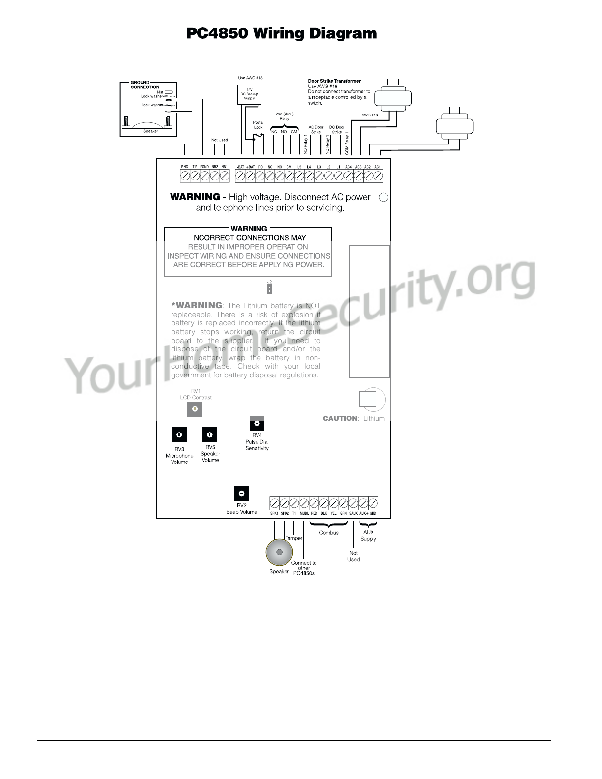
2.12 Connecting the PC4850 to Ground
Make a ground connection as shown below:
2.13 Connecting the Power
Once all other wiring is complete, power up the PC4850:
• After powering up the PC4850 for the first time, wait
for 10 seconds and then remove the shorting jumper J2.
During the normal operation of the PC4850, the
jumper must be kept removed.
• Connect the main board transformer to terminals AC1
and AC2, as shown.
2.14 Lithium Batteries
There is a lithium battery on the module. Do not attempt
to replace this battery. There is a danger of explosion if
the battery is incorrectly replaced.
If the lithium battery stops working, return the circuit
board to the supplier. Batteries may cause a fire when in
contact with metal. If you need to dispose of the circuit
board and/or the lithium battery, wrap the battery in
non-conductive tape. Check with your local government
for battery disposal regulations.
WARNI NG: Do not store the batteries in such a way
that they come into contact with each other or with
any piece of metal. Explosion or fire may occur. Should
fire occur, use only dry chemical fire extinguishers. Do
not use water to put out the fire.
Do not heat the batteries. Do not dispose of the batteries or circuit boards in a fire. Do not disassemble the
batteries. Do not apply pressure to or deform the batteries. Ensure that the above precautions are strictly
observed by related departments, including, but not
limited to, production, sales and outside contractors.
2.15 Connecting Tamper
Please see diagram below for connecting tamper.
GNDT1
• If connecting a backup battery, connect the red battery
lead to the +BAT terminal and the black lead to -BAT.
-BAT +BAT
~
12V
DC Backup
Supply
Use AWG #18
~
Normally Closed
Contact
4
Page 9

Section 3: Programming the PC4850
This section describes how the PC4850 modules works, and how to program it. You can program the PC4850 using either of
these methods:
• using a Maxsys system keypad
• using DLS-3 and a computer (see section 3.3, “Programming From DLS-3”, and the DLS-3 manual).
3.1 How the PC4850 Works
When the PC4850 is set up and running correctly, visitors
will be able to call the tenant they want to talk to and the
tenant will be able to open the door for them. Tenants
will also be able to enter the building using their access
code.
To Call a Tenant
When the PC4850 is not in use, the display will switch
between the initial greeting message and the following
message every few seconds:
To Find Tenant’s
Name, Press #
Visitors who know the tenant code for the person they
want to call can enter the code at any time. If no tenant
code is programmed, or if the visitors don’t know the
code, they can press [#] to find the name of the tenant
they want to call. When scrolling through tenant names,
the display shows (for example):
Jane Smith
[*]Prev. [#] Next
The visitor may also press the number key correspond-
ing to the first letter of the tenant names. This will dis-
play the first name in the list beginning with that letter.
For example, the [4] is associated with the letter “J”, “K”,
and “L”. Pressing the [4] key will display the first name
in the list beginning with “J”. Pressing [4] again will display the first name in the “K” list; pressing [4] again will
display the first name in the “L” list. When you have
arrived at the letter of the tenant’s name scroll to the tenant’s name as described above. If visitors find the correct
name and press [0], or if they have entered a valid tenant
code, the display changes to:
Calling Tenant,
To stop push “#”
If the tenant’s telephone line is busy, the PC4850 will
sound a 5-second busy tone and the display will show:
Line is Busy....
Please Try Again
The PC4850 will hang up the line if the tenant does not
answer after the call time programmed by the installer.
If the tenant answers the telephone, he or she can talk to
the visitor for the amount of time programmed by the
installer (from 0 – 99 seconds). At the last ten seconds of
talk time, the PC4850 will beep once and display a countdown of the last 10 seconds.
To Open the Door for a Visitor
• If tenants want to open the door for the visitor, they
can dial [7] on their telephone. When they open the
door, the speaker beeps once per second while the
door is unlocked, and the PC4850 display shows:
3.2 Programming PC4850 From a Keypad
3.3 Programming From DLS-3
3.4 Enrolling the PC4850
Door Unlocked,
Please Enter.
• If tenants want to open the alternate entrance (e.g., a
second door, or car gate), they can dial [9] on the telephone (Touch-Tone telephones only).
To Enter the Building Using an Entry Access Code
If tenants want to enter the building using the entry
access code they should:
1. Press [*] on the keypad.
2. Enter their access code. The PC4850 opens the door,
the speaker beeps once per second while the door is
unlocked, and the PC4850 display shows:
Door Unlocked,
Please Enter.
NOTE: When entering either the entry access code or
the tenant code, the PC4850 allows a maximum of 3
seconds between key presses. If you wait longer than
3 seconds before pressing the next key, the PC4850
will go back to the greeting displays.
You can program the PC4850 right from a system keypad
in the same way that you program other Maxsys modules. See your PC4020 Installation Manual for more information.
Record all your programming on the “Programming
Worksheet” on page 10.
You can program the PC4850 from a remote computer
using the DLS-3 software. To install and use the software,
refer to the DLS-3 manual.
Once you have finished wiring the PC4850 module, you
must enroll it on the PC4020 system. To enroll the module:
1. At a system keypad, enter Installer Programming by
pressing [*] [8] [Installer Code].
NOTE: The default Installer Code is [5555].
2. Scroll to “Module Hardware” and press the [*] key.
3. The message “Enroll Module” will appear. Press [*].
4. Scroll through the different modules until the module
you wish to enroll is displayed. Press the [*] key.
5. The keypad will display the message “Create Tamper
On Desired Unit.” Go to the PC4850 module to be
enrolled and tamper it. Return to the original keypad.
A message similar to the following will be displayed
to confirm enrollment: “PC4850 TCS Mod 02
Enrolled”.
5
Page 10

3.5 Programming Users’ Names, Telephone
Numbers, and Codes
To get the PC4850 up and running, you, or the building
staff, will need to program up to four items of information for each user:
• Access code (this is the same access code as for the rest
of the system)
• User name (the user name will be displayed on the
PC4850 LCD display so that visitors can find the user
to call him or her)
• User telephone number, or line number for the No-Bill
option (so that the system can call the user when there
is a visitor)
• Tenant code (optional - building staff can post a list of
tenant codes for visitors to enter on the keypad to call
users)
For visitors to be able to call a user, you must program a
telephone number, or telephone line number (if using the
No Bill option) for each user name.
Make copies of the Tenant Information Record Sheet on
page 11 to record user information.
To Program User Information:
1. At a system keypad, enter [*][5] followed by a [Mas-
ter Code].
2. The keypad displays:
Select (0) < >
User No. Search
Press [0] or [*].
3. The keypad displays:
Sel. Code (0001) < >
User 1
User 1 (Access Code 0001) is the System Master
Code. Use the right arrow (>) key to scroll to the user
you wish to program (for example, User 2). Press [*]
to select the user.
4. The keypad displays:
Select (0) < >
Program Code
This is the Program Code menu. Use the right arrow
(>) key to scroll though each display in the Program
Code menu. To select any menu item for programming, press [*].
Program Code
If users will enter an access code to enter the building or
to use security system functions, program the 4- or 6digit access code for each user here.
1. When the keypad displays: “Select (0) Program
Code.” press [0] or [*].
2. The display will indicate “Enter Digits” followed by
“AAAA.” This is the default setting for the access
code. Enter four or six digits for the new code.
3. Press [#]. The display will return to “Select (0) Pro-
gram Code.” The new code has been programmed.
NOTE: Do not program access codes that can be easily
guessed and will compromise the security of your system (e.g., 1111 or 1234).
Edit User Name
You must program a user name for each access code. To
program the user name:
1. From the Program Code menu, use the right arrow
(>) key to scroll to the following display:
Select (2) < >
Edit User Name
2. Press [2] or [*].
3. The display will read “Program Name.” For access
code 0002, the default name will be “User 2.” Enter
the new user name using the number keys in the following manner:
The letters of the alphabet have been divided up
among the 1 to 9 number keys on the keypad as follows:
[1] = A, B, C, 1 [2] = D, E, F, 2 [3] = G, H, I, 3
[4] = J, K, L, 4 [5] = M, N, O, 5 [6] = P, Q, R, 6
[7] = S, T, U, 7 [8] = V, W, X, 8 [9] = Y, Z, 9, 0
[0] = Space
For example, if you press the [4] key once, the letter
“J” will appear above the cursor on the display. Press
the [4] key again, the next letter “K” will appear, and
so on. If a different number key is pressed, the cursor
will automatically move to the right one space. To
erase a character, use the [<] [>] keys to move the cursor under the character, then press the [0] key.
NOTE: If a user does not want their name listed on
the PC4850 display, but does want to have an access
code, you can put a “!” at the beginning of the user
name. To enter a “!”, press [*], then scroll to the message “ASCII Entry”. Press [*], then enter [033*].
4. Once the new name has been entered, press [#]. The
display will return to “Select (2) Edit User Name.”
Access Code Label Options
There are other options available when programming
labels. When programming the label, press the [*] key for
the options menu. Use the arrow (< >) keys to scroll
through each option. Press the [*] key to select. The available options are:
• Clear Display: Selecting this option will clear the
entire code label.
• Clear to End: This will clear the display from the char-
acter where the cursor was located to the end of the
display.
• Change Case: This will toggle the letter entry between
uppercase and lowercase letters.
• ASCII Entry: This is for entering uncommon charac-
ters. Use the arrow (< >) keys to scroll through the
available characters. Each character will be displayed
along with the corresponding 3-digit ASCII number. If
you know the character’s 3-digit number, enter it.
Press the [*] key to enter the character into the code
label.
User Telephone or Telephone Line Number
Program the telephone number for each user. If you are
using the No Bill option, program the 3-digit telephone
line number provided by your telephone company
instead.
1. From the Program Code menu, use the right arrow
(>) key to scroll to the following display:
Select (5) < >
Phone Number
6
Page 11

2. Press [5] or [*].
3. Enter up to 12 digits for the telephone number. If you
are using the No Bill option, program the 3-digit telephone line number provided by your telephone company instead.
If you need to program special characters into the
telephone number, you can do this using hexadecimal digits. The following hexadecimal digits will
insert special characters into the telephone number:
NOTE: In the No Bill Option, programming of Hexadecimal digits is not allowed. Hexadecimal digits will
cause incorrect operation.
Special characters can be added to the telephone number
in order to perform designated functions. Press the [*] key
to enter the telephone entry options menu. The five
options are as follows:
[0] Save: This can be selected for the telephone num-
ber to be stored in the panel’s memory, or simply
press [#] when finished entering the telephone
number.
[1] Dial tone search: This character will force the
panel to search for a dial tone at that point in the
telephone number. A “D” on the display repre-
sents a dial tone search. A dial tone search is
already programmed as the first digit for each tele-
phone number.
[2] Pause 2 Seconds: This will add a 2-second pause to
the dialing sequence, represented by the letter “A”
on the display.
[3] Pause 4 Seconds: This will add a 4-second pause to
the dialing sequence, represented by the letter “E”
on the display.
[4] DTMF [*]: This will add an asterisk to the tele-
phone number, represented by a “B” on the dis-
play. The dialer will output the same frequencies
as the Touch-Tone [*] key. This character is frequently required to disable call waiting.
[5] DTMF [#]: This will add a “#” to the telephone
number, represented by the letter “C” on the display. The dialer will output the same frequencies
as the Touch Tone [#] key. In some instances, this
character is used to disable call waiting.
4. When you are finished, press [#].
Tenant Code (Optional)
You can give visitors the option of entering a 4-digit code
on the keypad to call a user. To do this, enter the 4-digit
code for the apartment. If a user knows a visitor is coming, they can give them the tenant code as a faster way to
call them.
1. From the Program Code menu, use the right arrow
(>) key to scroll to the following display:
Select (6) < >
Tenant Code
2. Press [6] or [*].
3. Enter up to 4 digits for the tenant code.
4. When you are finished, press [#].
Duplicate Entries
If the Duplicate Code toggle option is turned on in the
PC4020 programming, you will not be able to program
duplicate access codes. See your PC4020 Installa tion Man-
ual for more information.
NOTE: We recommend that users who have different
telephone numbers be given different tenant codes. If
you program more than one user with the same tenant code, the PC4850 will only call the user who is first
in alphanumeric order. Visitors will not be able to call
any other user using that code.
You can program users with the same name. However,
if users have exactly the same name, visitors will not
be able to distinguish between them when scrolling
through the list of names.
3.6 Programming the Greeting Display
Ref #: [0017XX03], where XX = PC4850 module number
The greeting display is what the LCD screen will show
when the system is not being used. The greeting display
is two lines of 16 characters. To change the greeting display:
1. Enter [*][8][Installer Code].
2. Enter reference number [0017XX03], where XX is the
number of the PC4850 module.
3. Press [*].
4. Enter the new user name using the number keys in
the following manner:
The letters of the alphabet have been divided up
among the 1 to 9 number keys on the keypad as follows:
[1] = A, B, C, 1 [2] = D, E, F, 2 [3] = G, H, I, 3
[4] = J, K, L, 4 [5] = M, N, O, 5 [6] = P, Q, R, 6
[7] = S, T, U, 7 [8] = V, W, X, 8 [9] = Y, Z, 9, 0
[0] = Space
For example, if you press the [4] key once, the letter
“J” will appear above the cursor on the display. Press
the [4] key again, the next letter “K” will appear, and
so on. If a different number key is pressed, the cursor
will automatically move to the right one space. To
erase a character, use the [<] [>] keys to move the cursor under the character, then press the [0] key.
5. To save the message, press [#].
3.7 Selecting Touch Tone or Pulse Dialing
Ref #: [0017XX00], where XX = PC4850 module number
The PC4850 can call users using either Touch-Tone or
pulse dialling formats. The default setting is for the
Touch-Tone format. To change the dialling format:
1. Enter [*][8][Installer Code].
2. Enter reference number [0017XX00], where XX is the
number of the PC4850 module.
3. Use the arrow (<>) keys to scroll until the display
shows:
DTMF Dialing
4. Press [*] to toggle the option on or off.
5. When you are finished, press [#].
3.8 Using the No Bill Option
Ref #: [0017XX00], where XX = PC4850 module number
Turn on the No Bill option if the PC4850 will use the
existing telephone connections in the building to call ten-
ants, and you have connected the PC4850 to a PC4851
unit. See section 2.8, “Connecting the PC4850 to a PC4851
(No Bill Option)”.
Do not turn on this option if the PC4850 will be using an
incoming telephone line to call tenants.
7
Page 12

1. Enter [*][8][Installer Code].
2. Enter reference number [0017XX00], where XX is the
number of the PC4850 module.
3. Use the arrow (<>) keys to scroll until the display
shows:
No Bill
4. Press [*] to toggle the option on or off.
5. When you are finished, press [#].
3.9 Changing the Battery Supervision Option
Ref #: [0017XX00], where XX = PC4850 module number
You can choose to have the PC4850 supervise the battery.
If the PC4850 supervises the battery, it will send the
panel a battery trouble when the battery is low.
1. Enter [*][8][Installer Code].
2. Enter reference number [0017XX00], where XX is the
number of the PC4850 module.
3. Use the arrow (<>) keys to scroll until the display
shows:
Battery Suprvs
4. Press [*] to toggle the option on or off.
5. When you are finished, press [#].
3.10 Setting the Talk Time, Door Time, Auxiliary
Relay, and the Call Time
Ref #: [0017XX01], where XX = PC4850 module number
You can change the settings for:
• length of time users can talk to visitors (Talk Time);
• length of time the door unlocks when a user presses [7]
on their telephone (Door Time);
• length of time for the auxiliary relay when a user
presses [9] on their telephone (Aux Rly Time).
Example: the auxiliary relay could control a gate to a
car entrance;
• the amount of time the PC4850 will wait for the user to
pick up the phone before canceling the call (Call Time).
To change any of these settings follow the steps below.
1. Enter [*][8][Installer Code].
2. Enter reference number [0017XX01], where XX is the
number of the PC4850 module.
3. To change the Talk Time, press [00].
To change the Door Time, press [01].
To change the Aux Rly Time, press [02].
To change the Call Time, press [03].
4. Enter the new 3-digit time for the timer you selected
(000-255 seconds).
5. Repeat steps 3 and 4 until you have programmed all
the timers.
NOTE: When using the No Bill option, the Call Time
should not be set for more than 60 seconds.
3.11 Setting up Access Codes for Two Building
Entry Points
Ref #: [0017XX02], where XX = PC4850 module number
The PC4850 can control two entry points (e.g., a door and
a car gate) using the door strike and the auxiliary relay
circuits. If the users will be using access codes to enter
the building, you can assign one set of codes to one entry
point and another set of codes to the second entry point.
To do this, tell the PC4850 what the last code will be for
the first entry point – this is the Entry Access Divider. For
example, if you set the divider to be 4999, codes from
0001 to 4999 will open the first entry point (e.g., the
building’s main door), and codes 5000 to 9999 will open
the second entry point (e.g., the car gate).
NOTE: With the setting (9999), none of the entry
access codes will open the 2nd entry point.
NOTE: When using the Entry Access Divider with a 6digit access code, only the first four digits of the
access code are used to determine which entry point
is unlocked.
To set the Entry Access Divider:
1. Enter [*][8][Installer Code].
2. Enter reference number [0017XX02], where XX is the
number of the PC4850 module.
3. Enter the 4-digit code that will be the divider
between the two access points. Valid entries are 0000
to 9999.
4. When you are finished, press [#].
3.12 Resetting to Factory Default Programming
You can reset all the PC4850 programming to factory
default settings.
To do this, create a temporary short on jumper J2 on the
PC4850 circuit board.
1. Power down the PC4850.
2. Create a short on J2.
3. Power up the PC4850.
4. Wait 10 seconds and remove the short.
NOTE: Cell phones shall not be programmed to allow
access.
8
Page 13

Section 4: Testing and Troubleshooting
4.1 Testing the PC4850
Once the PC4850 is connected and programmed, test
each of its functions to make sure it is working correctly.
The PC4850 should work as described in section 3.1,
“How the PC4850 Works”.
4.2 Troubleshooting
The PC4850 should work correctly without the need for
adjustments. However, if you encounter problems getting the unit to work, you can try adjusting the following
controls on the PC4850 circuit board. To adjust these controls, first, remove power from the PC4850 (AC and battery power), then use a small screwdriver to change the
appropriate setting.
LCD Contrast
If the LCD is hard to read, turn the control marked RV1
clockwise to increase the display contrast. To decrease
the display contrast, turn the control counter-clockwise.
“Beep” Volume
The PC4850 keypad beeps whenever a key is pressed.
You can adjust the volume of these beeps. To increase the
volume, turn the control marked RV2 clockwise. To
decrease the volume, turn the control counter-clockwise.
Microphone Volume
If users cannot hear visitors when they call using the
PC4850, turn the control marked RV3 clockwise to
increase the microphone sensitivity. To decrease the
microphone sensitivity, turn the control counter-clock-
wise.
Pulse Dial Sensitivity
If the PC4850 does not unlock the door when a user dials
9 using a pulse dial telephone, turn the control marked
RV4 clockwise or counter-clockwise 1/10 of a revolution,
until the door unlocks when 9 is dialed.
Speaker Volume
If visitors cannot hear the user they are calling on the
PC4850, turn the control marked RV5 clockwise to
increase the speaker sensitivity. To decrease the speaker
sensitivity, turn the control counter-clockwise.
4.3 “System is Busy. Please Wait” Message
Whenever the system displays this message, visitors will
not be able to call users using the PC4850, but users will
still be able to enter the building using their access codes.
Postal workers will also be able to enter if a postal lock
has been installed.
If this message is displayed, check for a Telephone Line
Trouble. This trouble will occur when the outgoing telephone line is disconnected from one or more units, or if
the telephone line is out of service. When the telephone
line is restored, the PC4850 will work normally. This
message is also displayed when another PC4850 current
has the line.
9
Page 14

Section 5: Programming Worksheet
Record your PC4850 programming here.
5.1 PC4850 Toggle Options
DTMF Dialing: I_____I Default = Y
No Bill:
Battery Suprvs:
5.2 Miscellaneous Options
Talk Time: 060 seconds
Door Time: 010 seconds I_____I_____I_____I
Aux Rly Time: 000 seconds I_____I_____I_____I
Call Time: 060 seconds I_____I_____I_____I
5.3 Entry Access Divider
I_____I_____I_____I_____I Default: [9999] Valid entries are 0000 to 9999.
5.4 Greeting Display
Default: [DSC Ltd.
I_____I Default = N
I_____I Default = N
Default
I_____I_____I_____I
MAXSYS]
Greeting Display:
I_____I_____I_____I_____I_____I_____I_____I_____I_____I_____I_____I_____I_____I_____I_____I_____I
I_____I_____I_____I_____I_____I_____I_____I_____I_____I_____I_____I_____I_____I_____I_____I_____I
10
Page 15

Tenant Information Record Sheet
NOTE: Make copies of this sheet for building staff to record tenant information.
User Name Telephone Number Tenant Code Access Code
I_____I_____I_____I_____I_____I_____I_____I_____I_____I_____I_____I_____I_____I_____I_____I_____I I_____I_____I_____I_____I_____I_____I_____I_____I_____I_____I_____I_____I I_____I_____I_____I_____I I_____I_____I_____I_____I_____I_____I
I_____I_____I_____I_____I_____I_____I_____I_____I_____I_____I_____I_____I_____I_____I_____I_____I I_____I_____I_____I_____I_____I_____I_____I_____I_____I_____I_____I_____I I_____I_____I_____I_____I I_____I_____I_____I_____I_____I_____I
I_____I_____I_____I_____I_____I_____I_____I_____I_____I_____I_____I_____I_____I_____I_____I_____I I_____I_____I_____I_____I_____I_____I_____I_____I_____I_____I_____I_____I I_____I_____I_____I_____I I_____I_____I_____I_____I_____I_____I
I_____I_____I_____I_____I_____I_____I_____I_____I_____I_____I_____I_____I_____I_____I_____I_____I I_____I_____I_____I_____I_____I_____I_____I_____I_____I_____I_____I_____I I_____I_____I_____I_____I I_____I_____I_____I_____I_____I_____I
I_____I_____I_____I_____I_____I_____I_____I_____I_____I_____I_____I_____I_____I_____I_____I_____I I_____I_____I_____I_____I_____I_____I_____I_____I_____I_____I_____I_____I I_____I_____I_____I_____I I_____I_____I_____I_____I_____I_____I
I_____I_____I_____I_____I_____I_____I_____I_____I_____I_____I_____I_____I_____I_____I_____I_____I I_____I_____I_____I_____I_____I_____I_____I_____I_____I_____I_____I_____I I_____I_____I_____I_____I I_____I_____I_____I_____I_____I_____I
I_____I_____I_____I_____I_____I_____I_____I_____I_____I_____I_____I_____I_____I_____I_____I_____I I_____I_____I_____I_____I_____I_____I_____I_____I_____I_____I_____I_____I I_____I_____I_____I_____I I_____I_____I_____I_____I_____I_____I
I_____I_____I_____I_____I_____I_____I_____I_____I_____I_____I_____I_____I_____I_____I_____I_____I I_____I_____I_____I_____I_____I_____I_____I_____I_____I_____I_____I_____I I_____I_____I_____I_____I I_____I_____I_____I_____I_____I_____I
I_____I_____I_____I_____I_____I_____I_____I_____I_____I_____I_____I_____I_____I_____I_____I_____I I_____I_____I_____I_____I_____I_____I_____I_____I_____I_____I_____I_____I I_____I_____I_____I_____I I_____I_____I_____I_____I_____I_____I
I_____I_____I_____I_____I_____I_____I_____I_____I_____I_____I_____I_____I_____I_____I_____I_____I I_____I_____I_____I_____I_____I_____I_____I_____I_____I_____I_____I_____I I_____I_____I_____I_____I I_____I_____I_____I_____I_____I_____I
I_____I_____I_____I_____I_____I_____I_____I_____I_____I_____I_____I_____I_____I_____I_____I_____I I_____I_____I_____I_____I_____I_____I_____I_____I_____I_____I_____I_____I I_____I_____I_____I_____I I_____I_____I_____I_____I_____I_____I
I_____I_____I_____I_____I_____I_____I_____I_____I_____I_____I_____I_____I_____I_____I_____I_____I I_____I_____I_____I_____I_____I_____I_____I_____I_____I_____I_____I_____I I_____I_____I_____I_____I I_____I_____I_____I_____I_____I_____I
I_____I_____I_____I_____I_____I_____I_____I_____I_____I_____I_____I_____I_____I_____I_____I_____I I_____I_____I_____I_____I_____I_____I_____I_____I_____I_____I_____I_____I I_____I_____I_____I_____I I_____I_____I_____I_____I_____I_____I
I_____I_____I_____I_____I_____I_____I_____I_____I_____I_____I_____I_____I_____I_____I_____I_____I I_____I_____I_____I_____I_____I_____I_____I_____I_____I_____I_____I_____I I_____I_____I_____I_____I I_____I_____I_____I_____I_____I_____I
I_____I_____I_____I_____I_____I_____I_____I_____I_____I_____I_____I_____I_____I_____I_____I_____I I_____I_____I_____I_____I_____I_____I_____I_____I_____I_____I_____I_____I I_____I_____I_____I_____I I_____I_____I_____I_____I_____I_____I
I_____I_____I_____I_____I_____I_____I_____I_____I_____I_____I_____I_____I_____I_____I_____I_____I I_____I_____I_____I_____I_____I_____I_____I_____I_____I_____I_____I_____I I_____I_____I_____I_____I I_____I_____I_____I_____I_____I_____I
I_____I_____I_____I_____I_____I_____I_____I_____I_____I_____I_____I_____I_____I_____I_____I_____I I_____I_____I_____I_____I_____I_____I_____I_____I_____I_____I_____I_____I I_____I_____I_____I_____I I_____I_____I_____I_____I_____I_____I
I_____I_____I_____I_____I_____I_____I_____I_____I_____I_____I_____I_____I_____I_____I_____I_____I I_____I_____I_____I_____I_____I_____I_____I_____I_____I_____I_____I_____I I_____I_____I_____I_____I I_____I_____I_____I_____I_____I_____I
I_____I_____I_____I_____I_____I_____I_____I_____I_____I_____I_____I_____I_____I_____I_____I_____I I_____I_____I_____I_____I_____I_____I_____I_____I_____I_____I_____I_____I I_____I_____I_____I_____I I_____I_____I_____I_____I_____I_____I
I_____I_____I_____I_____I_____I_____I_____I_____I_____I_____I_____I_____I_____I_____I_____I_____I I_____I_____I_____I_____I_____I_____I_____I_____I_____I_____I_____I_____I I_____I_____I_____I_____I I_____I_____I_____I_____I_____I_____I
I_____I_____I_____I_____I_____I_____I_____I_____I_____I_____I_____I_____I_____I_____I_____I_____I I_____I_____I_____I_____I_____I_____I_____I_____I_____I_____I_____I_____I I_____I_____I_____I_____I I_____I_____I_____I_____I_____I_____I
I_____I_____I_____I_____I_____I_____I_____I_____I_____I_____I_____I_____I_____I_____I_____I_____I I_____I_____I_____I_____I_____I_____I_____I_____I_____I_____I_____I_____I I_____I_____I_____I_____I I_____I_____I_____I_____I_____I_____I
I_____I_____I_____I_____I_____I_____I_____I_____I_____I_____I_____I_____I_____I_____I_____I_____I I_____I_____I_____I_____I_____I_____I_____I_____I_____I_____I_____I_____I I_____I_____I_____I_____I I_____I_____I_____I_____I_____I_____I
I_____I_____I_____I_____I_____I_____I_____I_____I_____I_____I_____I_____I_____I_____I_____I_____I I_____I_____I_____I_____I_____I_____I_____I_____I_____I_____I_____I_____I I_____I_____I_____I_____I I_____I_____I_____I_____I_____I_____I
I_____I_____I_____I_____I_____I_____I_____I_____I_____I_____I_____I_____I_____I_____I_____I_____I I_____I_____I_____I_____I_____I_____I_____I_____I_____I_____I_____I_____I I_____I_____I_____I_____I I_____I_____I_____I_____I_____I_____I
11
Page 16

AVIS: L’étiquette de l’Industrie Canada identifie le matériel homologué. Cette étiquette certifie que le matériel est conforme à certaines
normes de protection, d’exploitation et de sécurité des réseaux de télécommunications. Industrie Canada n’assure toutefois pas que le matériel fonctionnera à la satisfaction de l’utilisateur.
Avant d’installer ce matériel, l’utilisateur doit s’assurer qu’il est permis
de le raccorder aux installations de l’entreprise locale de télécommunication. Le matériel doit également être installé en suivant une méthode
acceptée de raccordement. L’abonné ne doit pas oublier qu’il est possible que la conformité aux conditions énoncées ci-dessus n’empêchent
pas la dégradation du service dans certaines situations.
Les réparations de matériel homologué doivent être effectuées par un
centre d’entretien canadien autorisé désigné par le fournisseur. La
compagnie de télécommunications peut demander à l’utilisateur de
débrancher un appareil à la suite de réparations ou de modifications
effectuées par l’utilisateur ou à cause de mauvais fonctionnement.
Pour sa propre protection, l’utilisateur doit s’assurer que tous les fils de
mise à la terre de la source d’énergie électrique, les lignes téléphoniques et les canalisations d’eau métalliques, s’il y en a, sont raccordés
ensemble. Cette précaution est particulièrement importante dans les
régions rurales.
AVERTISSEMENT: L’utilisateur ne doit pas tenter de faire ces raccordements lui-même; il doit avoir recours à un service d’inspection des
installations électriques, ou à un électricien, selon le cas.
Indice d’équivalence de la sonnerie (IÉS) assigné a chaque dispositif
terminal indique, pour éviter toute surcharge, le pourcentage de la
charge totale qui peut être raccordée à un circuit téléphonique bouclé
utilisé par ce dispositif. La terminaison du circuit bouclé peut être con-
stituée de n’importe quelle combinaison de dispositifs, pourvu que la
somme des indices d’équivalence de la sonnerie de l’ensemble des dis-
positifs ne dépasse pas 5.
Indice d’équivalence de la sonnerie de ce produit est 0.1.
NOTICE: The Industry Canada label identifies certified equipment.
This certification means that the equipment meets certain telecommunications network protective, operational and safety requirements.
Industry Canada does not guarantee the equipment will operate to the
user’s satisfaction.
Before installing this equipment, users should ensure that it is permissible to be connected to the facilities of the local telecommunications
company. The equipment must also be installed using an acceptable
method of connection. The customer should be aware that compliance
with the above conditions may not prevent degradation of service in
some situations.
Repairs to certified equipment should be made by an authorized Canadian maintenance facility designated by the supplier. Any repairs or
alterations made by the user to this equipment, or equipment malfunctions, may give the telecommunications company cause to request the
user to disconnect the equipment.
User should ensure for their own protection that the electrical ground
connections of the power utility, telephone lines and internal metallic
water pipe system, if present, are connected together. This precaution
may be particularly important in rural areas.
CAUTION: Users should not attempt to make such connections themselves, but should contact the appropriate electric inspection authority,
or electrician, as appropriate.
The Ringer Equivalence Number (REN) assigned to each terminal
device denotes the percentage of the total load to be connected to a
telephone loop which is used by the device, to prevent overloading.
The termination on a loop may consist of any combination of devices
subject only to the requirement that the total of the Ringer Equivalence
Number of all the devices does not exceed 5.
The Ringer Equivalence number of this unit is 0.1.
©2002 Digital Security Controls Ltd.
Technical Support: 1-800-387-3630
Toronto, Canada • www.dsc.com
Printed in Canada 29005231 R004
Direct all comments concerning this
publication to pubs@dscltd.com.
 Loading...