

Page 1
PC4702BP Power Supply/Bell Panel
Installation Instructions
1. Introduction
The PC4702BP is a power supply/bell panel for use with
PC4010CF and PC4020CF Maxsys security systems. Up
to 4 modules may be installed on one system.
For more information on PC4010CF/4020CF options and
programming, please refer to your PC4010CF/4020CF
Commercial Fire Installation Guide.
2. Specifications
• Connects to control panel via 4-wire Combus
• Current Draw: 30 mA (from Combus)
• Two supervised Class ‘B’/Style ‘B’ Bell outputs: 24
DC FWR, 1.5A each, maximum 2.5A combined
V
current draw. Outputs supervised for opens, shorts
and ground with self-restoring short protection
• Supervised battery charger, 24 V
current for sealed lead-acid rechargeable batteries
• Power transformer: 28 VAC, 175 VA ( mounted in
cabinet )
DC, 350 mA charging
3. Installing the PC4702BP
3.1 Unpacking
The PC4702BP package includes the following parts:
• One PC4702 circuit board
• one PT1024 28V
• Four plastic stand-offs (for PC4702 board)
• One - PC4052CR red cabinet, or PC4052C beige
cabinet – 12.0”W x 12.0”H x 4.5”D with space for two
DC, 4.0Ah sealed lead-acid rechargeable batteries
12 V
• Two listed 2200Ω resistors
AC, 175VA transformer
3.2 Mounting
Install the PC4702BP in the PC4052CP cabinet, mounted
in a dry, secure location at a convenient distance from the
connected devices.
Perform the following steps to mount the unit:
1. Press the four plastic stand-offs through the mounting
holes at back of the cabinet.
2. Secure the cabinet to the wall in the desired location.
Use appropriate wall anchors when securing the
cabinet to drywall, plaster, concrete, brick or other
surfaces.
3. Press the circuit board into the plastic stand-offs to
secure the module to the cabinet.
Once the unit is mounted, wiring may be completed.
3.3 Installation and Wiring
Before beginning to wire the unit, ensure that all power
(AC transformer and battery) is disconnected from the
control panel.
Perform the following steps to complete wiring:
1. Connect the four Combus wires to the PC4702BP.
Connect the red, black, yellow and green Combus
wires to the RED, BLK, YEL and GRN terminals,
respectively.
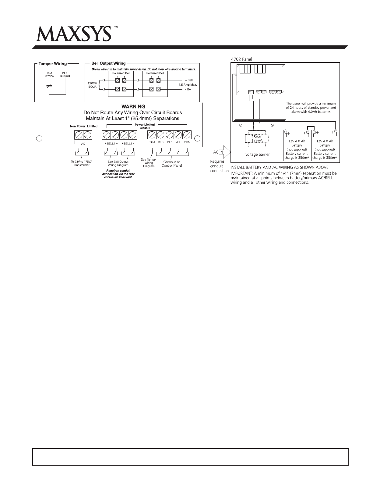
2. Complete all other wiring according to the wiring
diagrams above.
3. Consult the wiring chart on the back of this sheet.
3.4 Applying Power
After all wiring is completed, apply power to the control
panel. Connect the battery leads to the battery, then connect
the AC transformer. For more information on control panel
power specifications, see the control panel Installation
Manual.
NOTE: Do not connect the power until all wiring is
complete.
Please refer to the System Installation Manual for information on limitations regarding product
use and function and information on the limitations as to liability of the manufacturer.
Page 2

4. Enrolling the Module
Once all wiring is complete, the module must be enrolled
on the system. To enroll the module:
1. Enter installer’s programming by pressing [*] [8]
[Installer’s Code].
2. Scroll to “Module Hardware” and press the [*] key.
3. Scroll to “Enroll Module” and press the [*] key.
4. Scroll through the different modules until “PC4702
Fire” is displayed. Press the [*] key.
5. The keypad will prompt, “Create tamper on desired
unit.” After you create and restore the tamper (see
Tamper Wiring on front), the keypad will confirm
enrollment (e.g. “PC4702 Fire Mode XX Enrolled”).
For more information regarding module enrollment, see
the control panel Installation Manual.
5. Programming the Module
To access PC4010/PC4020 programming, enter [*][8]
followed by the Installer’s code.
Enter the reference numbers indicated below to jump to
the PC4702BP programming sections. Enter one of the
recommended output options and which partition(s) the
output will be active on for each output. Record your
programming choices in the space below.
You may also need to program the following sections:
Ref #: [000200] Fire Timeout (Y)
Ref #: [00020300] Bell Cut-off (005)
Ref #: [00020309] Fire Silence Del (000)
Refer to your control panel Installation Manual for more
information on these programming sections. Record
your programming choices for these sections in your
control panel’s Programming Worksheets book.
Record your PC4702BP programming choices here:
Output Partition
Option 1 2 3 4 5 6 7 8
PC4702 module no.: 01
[0007070101] Bell Output 1 I
[0007070102] Bell Output 2 I
______I______
______I______
Location: __________________________________________________________
PC4702 module no.: 02
[0007070201]
Bell Output 1 I
[0007070202] Bell Output 2 I
______I______
______I______
Location: __________________________________________________________
______I______I______I______I______I______I______I______
II
______I______I______I______I______I______I______I______
II
______I______I______I______I______I______I______I______
II
______I______I______I______I______I______I______I______
II
I
I
Recommended Output
Options:
[49] Steady Fire
[50] Temporal Fire
[51] CSFM Fire
[52] Pulsed Fire
I
I
[53] Fire Strobe
PC4702 module no.: 03
[0007070301]
Bell Output 1 I
[0007070202] Bell Output 2 I
______I______
______I______
______I______I______I______I______I______I______I______
II
______I______I______I______I______I______I______I______
II
Location: __________________________________________________________
PC4702 module no.: 04
[0007070401]
Bell Output 1 I
[0007070202] Bell Output 2 I
______I______
______I______
______I______I______I______I______I______I______I______
II
______I______I______I______I______I______I______I______
II
Location: __________________________________________________________
This unit may contain a time limit cut-out on the bell circuit.
Programmed cut-out time is ___________.
Bell Loop Wiring Chart
To ensure proper operation, the wire length of the bell
loop must be considered.
Consult the following chart to determine the maximum
wire length for the bell loop with respect to current.
Bell Loop
Load
Current
1.8A 51/16 81/25 129/39
1.0A 92/28 147/44 233/70
0.7A 132/40 210/64 332/101
0.5A 184/56 293/89 465/141
0.1A 922/279 1467/445 2326/705
I
I
I
I
Distance to last bell/siren (ft/m)
18 AWG
Wire
16 AWG
Wire
14 AWG
Wire
©2000 Digital Security Controls Ltd.
Toronto, Canada • 1-800-387-3630 • www.dsc.com
Printed in Canada 29005212 R001
 Loading...