

Page 1
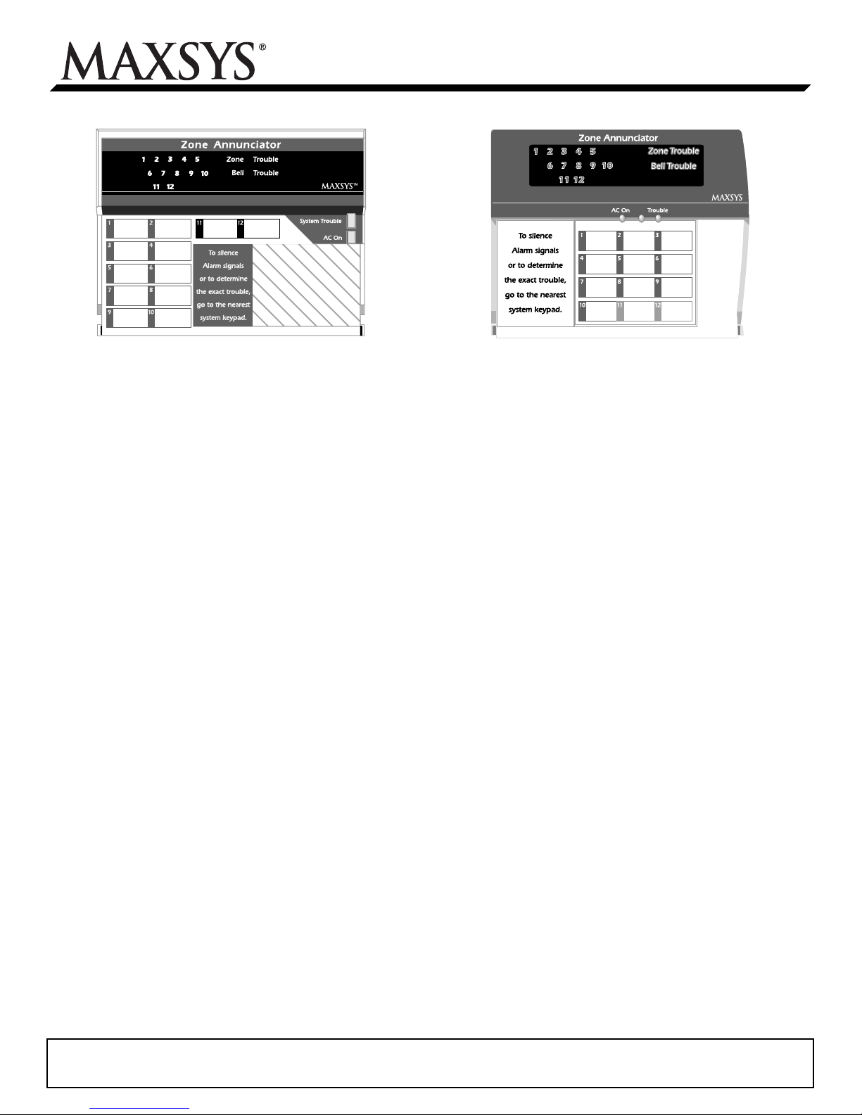
PC4612(A) Zone Annunciator
Installation Instructions
PC4612
1. Introduction
The PC4612(A) is a 12-zone annunciator for use with PC4010/PC4020
security systems. You can install a combined total of 9 PC4612(A) and
PC4216 modules on each PC4010/4020 system.
2. Specifications
• Style PC4612 or PC4612A available
• 16 programmable LEDs
• Four wire (QUAD) hook-up to Combus
• Nominal current draw of 15mA
• Tamper and trouble reporting
• Supervision by control panel via Combus
3. Installation
Connect the PC4612(A) to the panel via the Combus. Be sure to include the current draw of the PC4612(A) (15mA) in your Combus current calculation. Refer to your PC4010/4020 Installation Manual for
more information on Combus wiring.
4. Enrolling and Programming the PC4612(A)
Follow the instructions below for enrolling and programming your
PC4612(A) module. If you are enrolling the module on a PC4010/4020
v3.0 or greater system, you can use the reference numbers (indicated
by the square brackets, eg. [0200]) to jump to a programming section.
Refer to your system's installation or programming manual for more
information on programming.
4.1 Enrolling
You must enroll the PC4612(A) module with your panel before you
can program it. The PC4612(A) is enrolled exactly as if it were a
PC4216 module. Follow these steps:
1. At a PC4010/4020 system LCD keypad, enter Installer's Programming ([*][8][Installer’s code]).
2. Enter Ref #[0200][*] OR scroll to Module Hardware, press [*],
then, scroll to Enroll Module, press [*].
3. Scroll to PC4216 Module, press [*]. The LCD keypad displays
Create Tamper on Desired Unit.
4. Tamper and then restore the PC4612(A):
a) Remove the screws on the bottom of the unit.
b) Pull the front plastic of the unit approximately Ό" away from
the backplate.
c) Replace the front of the unit and the screws in their original
locations. The LCD keypad displays PC4216 Mod 01 Enrolled.
PC4612A
5. Record the module number in the worksheet area on the back of
this instruction sheet.
6. To exit Module Enrollment, press [#].
4.2 Programming
On the PC4612(A), each of the 16 outputs controls a particular LED. Outputs 1-12 control the LEDs which light up numbers 1-12 on the Annunciator. Outputs 13-16 control the LEDs which light up the Zone Trouble,
Bell Trouble, System Trouble and AC On indicators, respectively.
A Custom Group is a set of 16 programming choices which correspond
to the 16 programmable outputs on each PC4612(A) module. Each
LED will function according to the programming of its output in the
assigned custom group.
To program the PC4612(A), you need to assign a custom group to the
module, and to make sure that the outputs of the assigned custom
group are programmed appropriately. Example: the PC4612(A) is assigned to custom group (01). In this custom group, output (05) is programmed to follow zone
(020), which is a fire zone. This was done by programming output (05)
for option (22) zone follow. When zone (020) is in alarm, LED 5 turns
on. When zone (020) is restored and a fire reset is performed, LED 5
turns off.
The PC4612(A) uses the same programming as the PC4216, and is
therefore done in the same programming sections. These sections are
described below as they relate to the PC4612(A). For instructions on
how to program the PC4010/4020 and its modules, refer to your
PC4010/4020 Installation Manual. For information on programming
PC4216 modules, refer to your PC4216 Installation Instructions.
1. Choose a Custom Group
Ref #: [000703XX] where XX = 01-09 (PC4612(A) number) Program
each PC4612(A) to use one of nine custom groups. More than one module may follow the same custom group. Enter the number of the custom
group the PC4612(A) will follow (enter 01-09). To exit, press [#].
2. Program a Custom Group
Ref #: [000704XX] where XX = 01-09 (Custom Group 01-09) A custom group is a set of 16 programmed output options. Each output in a
custom group can be programmed to operate according to a different
output option.
1. Choose the output to be programmed (01-16)
2. Enter the number of the output option to be used for that output.
3. To exit, press [#].
Please refer to the System Installation Manual for information on limitations regarding product use
and function and information on the limitations as to liability of the manufacturer.
Page 2

The recommended output options for the PC4612(A) are (21), (22),
(48), (55), (56), (57). Their descriptions are listed below.
4.3 Recommended Output Options
Zone Alarm (21)
For zones that are programmed as burglary, the zone alarm output will
activate the LED when the selected burglary zone has gone into
alarm.The LED will remain on until the partition is armed again.
Zone Follow (22)
For zones that are programmed as Fire or Fire Supervisory, the zone
follow output will turn on the LED when the fire zone is in alarm, or
when the fire supervisory zone is off-normal (zone shorted). The LED
will only turn off when the zone has been restored and a fire reset has
been performed.
Outputs 1-10 have red LEDs and are intended for fire/burglary alarm
zone annunciation. Outputs 11-12 have yellow LEDs and are intended
for fire supervisory zone annunciation.
NOTE: Use Options 21 or 22 for output numbers 01-10 and option 22
only for output numbers 11-12.
Fire Zone Tbl. (48)
The output will activate when a fire zone is bypassed, or when a fire
zone trouble condition is detected. The output will deactivate when the
zone is unbypassed or the trouble is restored. Use this option for
PC4612(A) output number 13.
Common Fire Tbl. (55)
The output activates when any of the following troubles are detected
by the panel. The output deactivates when the trouble is cleared:
• Any system AC or battery trouble (PC4020, PC4820, PC4204,
PC4701)
• Any system communicator trouble (TLM1, TLM2, FTC, LINKS)
• Ground Fault trouble
NOTE: Use this option for PC4612(A) output number 15.
Bell Trouble (56)
The output activates for a trouble (open or short) on any supervised
system bell output (PC4010/4020 or PC4702). The output deactivates
when the trouble is cleared. Use this option for PC4612(A) output
number 14.
AC Status (57)
The output will be ON when AC power is present on the PC4010/
4020, as well as all enrolled modules (PC4204, PC4820, PC4702). If
the PC4010/4020 or any module loses AC power, the AC Fail Delay
timer will start (see your PC4010/4020 Installation Manual for more
information). When the timer expires (or if it is programmed to be 0),
if the AC is still missing, the output will turn OFF. An AC Fail trouble
condition will be generated. When AC power is restored, the output
will again wait for the AC Fail Delay timer to expire. If the AC power
is still on at the end of the delay, the output will turn ON. Use this option for PC4612(A) output number 16.
4.4 Finishing
Make sure you label each of the 12 zone lights in the space provided
on the annunciator. When you have finished installing and programming the PC4612(A), instruct the end-user of the system how to interpret events using the annunciator.
PC4612(A) Programming PC4612(A) Module No.:
[000703XX] PC4216 Options XX = module# [Enter 01 - 09] Custom Group No:
l__________l__________l
l__________l__________|
[000704XXYY] PC4216 Custom XX = custom group # [Enter 01 - 09]; YY = output # [Enter 01 - 16]
Output# PC4612 LED
1 1 21 or 22
2 2 21 or 22
3 3 21 or 22
4 4 21 or 22
5 5 21 or 22
6 6 21 or 22
7 7 21 or 22
8 8 21 or 22
9 9 21 or 22
10 10 21 or 22
11 11 22
12 12 22
13 Zone Trouble 48
14 Bell Trouble 56
15 System Trouble 55
16 AC On 57
For Zone
Alarms
(Red)
For Fire Supervisory
(Yellow)
Yellow
Green
Recommended
Option
Output
Option
l__________l__________l
l__________l__________l
l__________l__________l
l__________l__________l
l__________l__________l
l__________l__________l
l__________l__________l
l__________l__________l
l__________l__________l
l__________l__________l
l__________l__________l
l__________l__________l
l__________l__________l
l__________l__________l
l__________l__________l
l__________l__________l
Zone
l________l________ l________l_
l________l________ l________l_
l________l________ l________l_
l________l________ l________l_
l________l________ l________l_
l________l________ l________l_
l________l________ l________l_
l________l________ l________l_
l________l________ l________l_
l________l________ l________l_
l________l________ l________l_
l________l________ l________l_
Select zone 001-128 (PC4020), 001-064 (PC4010)
Select zone 001-128 (PC4020), 001-064 (PC4010)
Select zone 001-128 (PC4020), 001-064 (PC4010)
Select zone 001-128 (PC4020), 001-064 (PC4010)
Select zone 001-128 (PC4020), 001-064 (PC4010)
Select zone 001-128 (PC4020), 001-064 (PC4010)
Select zone 001-128 (PC4020), 001-064 (PC4010)
Select zone 001-128 (PC4020), 001-064 (PC4010)
Select zone 001-128 (PC4020), 001-064 (PC4010)
Select zone 001-128 (PC4020), 001-064 (PC4010)
Select zone 001-128 (PC4020), 001-064 (PC4010)
Select zone 001-128 (PC4020), 001-064 (PC4010)
©2002 Digital Security Controls Ltd.
Toronto, Canada • www.dsc.com
Tech Support: 1-800-387-3630 (Canada & US) or 905-760-3036
Printed in Canada 29002625 Rev 003
Direct all comments concerning this publication to pubs@dscltd.com
 Loading...