

Page 1

Programming Manual
PC4O1O Software Version 2.1
Book 2
Page 2

Table of Contents
Programming the PC4010
Programming Toggle Options ________________________________________________________ 2
Programming HEX Digits ____________________________________________________________ 2
Programming Manual ___________________________________________________________3
Installer options _______________________________________________________________4
Event Messages _______________________________________________________________5
System Options
System Toggle Options _____________________________________________________________ 7
Keypad Toggle Options ____________________________________________________________ 11
Keypad Lockout Options ___________________________________________________________ 12
System Times _____________________________________________________________________ 12
Zone Supervision _________________________________________________________________ 12
Download Section
Download Toggles ________________________________________________________________ 13
DLS Options ______________________________________________________________________ 14
Communicator Section
Main Items - Phone Numbers/Communication Format/Dialer Direction ___________________ 15
Communicator Toggles ____________________________________________________________ 24
Communicator Miscellaneous ______________________________________________________ 27
Test Code Transmission ___________________________________________________________ 27
Reporting Codes __________________________________________________________________ 27
Links Module _____________________________________________________________________ 32
Switched Auxiliary Output ______________________________________________________ 34
Main Bell Output ______________________________________________________________ 35
PGM Outputs
Main PGM Output _________________________________________________________________ 36
PC4204 Options __________________________________________________________________ 36
PC4216 Options __________________________________________________________________ 36
PC4216 Custom___________________________________________________________________ 37
Escort4580 Automation Items _______________________________________________________ 37
PGM Pulse Times _________________________________________________________________ 37
PGM Outputs List _____________________________________________________________38
PC4400 Options ______________________________________________________________ 41
System Label_________________________________________________________________44
Event Scheduling _____________________________________________________________45
Add / Edit Partitions
Partition Toggles __________________________________________________________________ 49
Partition Times ____________________________________________________________________ 51
Zone Assignment _________________________________________________________________ 52
Zone Type________________________________________________________________________ 52
Zone Options _____________________________________________________________________ 55
Partition Label ____________________________________________________________________ 55
Delete/Copy Partition __________________________________________________________ 56
Module Hardware
Enroll Module _____________________________________________________________________ 57
Delete Module ____________________________________________________________________ 58
Confirm Module ___________________________________________________________________ 58
RF Zone Options __________________________________________________________________ 58
RF Zones - Summary ______________________________________________________________ 60
Event Buffer _________________________________________________________________ 61
Diagnostics __________________________________________________________________62
Appendix A
List of Available ASCII Characters ___________________________________________________ 63
Appendix B
List of Diagnostics_________________________________________________________________ 64
1
Page 3

PROGRAMMING
THE PC4010
The PC4010 incorporates a new method of programming which uses a menu system to find a specific program location
when it is to be entered.
Book 3 contains the programming flow charts for the PC4010. The charts are arranged in such a way as to allow you to
quickly find any option and the path required to arrive at the program location. In addition you will be able to see other
options also available to you in the program area.
Plain boxes are program areas and shaded boxes are menu selections.
Two methods may be used to select the different menu items to arrive at a program location. With the first, you may use
the arrow keys (< >) to scroll through the menu items. When the desired item is displayed press the [Q] key. The [Q] key
is used as an ‘ENTER’ or ‘SELECT’ key. The panel will then move you to the next set of options.
The other method incorporates a ‘HOTKEY’ system. Every menu and program item contains a one or two digit ‘HOTKEY’
entry. Simply press the number(s) in the menu or program box and the panel will automatically select the item for you.
DO NOT PRESS THE [Q] AFTER ENTERING THE ‘HOTKEY’ NUMBER. This second method is much quicker once you
become familiar with it.
EXAMPLE: We wish to program the Exit Delay for Partition 4. The following is the flow chart located in Book 3.
SYSTEM AREA
Ô
PARTITION AREA
Scroll to desired option using
(0) the [<][>] keys and press [Q].
ADD/EDIT PAR
þ
(1) (0) (1)
WHICH PARTITION
þ
CUSTOMER ID CODE
þ
Ô (4) (0)
PAR TOGGLES
þ
PARTITION TIMES
þ
(1)
(2) (0)
ENTRY DELAY
þ
EXIT DELAY
þ
(1)
Using the first method the arrow keys would have to be pressed many times to scroll to the various items followed by the
[Q] key to select the item. Twelve keystrokes would be required after entering Installer Programming providing no
mistakes are made. The keystrokes required are as follows:
[>], [Q] to select PARTITION AREA [>], [>], [Q] to select PARTITION TIMES
[Q] to select ADD/EDIT PAR [>], [Q] to select EXIT DELAY
[>], [>], [>], [Q]to select to PARTITION 4
Using the second ‘HOTKEY’ method we require only 5 keystrokes:
[1] to select PARTITION AREA [2] to select PARTITION TIMES
[0] to select ADD/EDIT PAR [1] to select EXIT DELAY
[4] to select PARTITION 4
With less keystrokes required, programming is quicker as there is less chance of an error occurring.
At any time you may press the [#] key to exit a section. ANY DATA ENTERED WILL BE CHANGED. THE [#] KEY IS NOT
AN ABORT KEY! The [#] key can also be pressed to move you back to the previous menu. Pressing the [#] key several
times will exit you from Installer Programming.
To make programming easier the INDEX at the back of the Programming Manual includes the chart number beside every
option as well as the page number for a description of the option.
Programming Toggle Options
Some program areas contain several toggle options which pertain to the menu item selected. Use the arrow keys (<>) to
scroll through the various items. Press the [Q] key to toggle between [Y]es and [N]o for each feature. Once all the toggle
options have been programmed press the [#] key to save your changes and return to the previous menu.
Programming HEX Digits
Often HEX digits are required for a program item. When a HEX digit is required press the [Q] key to enter the HEX menu.
You may use the arrow keys to scroll through the HEX digits (A through F) and when the desired letter is displayed press
the [Q] key.
Another much quicker method for entering HEX digits is to, first, press the [Q] key followed by the number corresponding
to the HEX letter i.e. A = 1, B = 2, C = 3, up to F = 6. The [Q] key must be pressed before entering each HEX digit as the
software returns you to decimal programming automatically after each entry.
EXAMPLE: To enter data ‘ABCD’ on a PC4010 you would enter:
[Q], [1], [Q], [2], [Q], [3], [Q], [4]
Note: The [Q] key is required before every HEX digit entered.
2
Page 4
PROGRAMMING
MANUAL
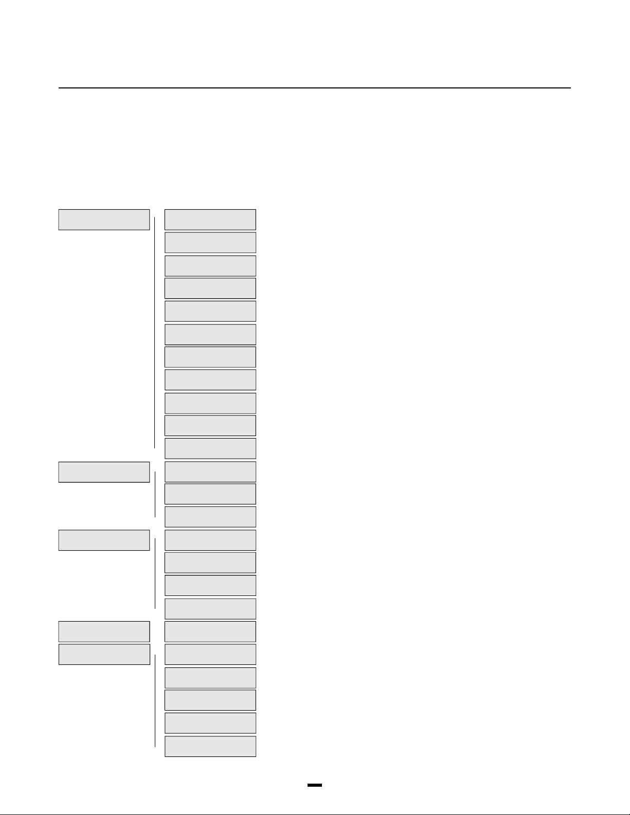
The PC4010 Installer’s Programming is broken down into 5 major sections:
System Area For programming options which affect the operation of the entire system. For example communications,
downloading, printer options etc. are options which affect the overall system and are programmed in the system area.
Partition Area For programming options which pertain to individual partitions. For example the zone assignment, entry
delay time and exit delay time are all options which can be programmed for each of the partitions.
Module Hardware For enrolling and deleting modules.
Event Buffer For the installer to reprint the entire event buffer.
Diagnostics For viewing trouble conditions reported by the modules.
SYSTEM AREA
PARTITION AREA
MODULE HARDWARE
EVENT BUFFER
DIAGNOSTICS
INSTALLER OPT’S __________________________________________ 4
þ
(0) (00)
EVENT MESSAGES __________________________________________ 5
þ
SYSTEM OPTIONS __________________________________________ 7
þ
DLS SECTION __________________________________________ 13
þ
COMMUNICATOR __________________________________________ 15
þ
SW AUX OUTPUT __________________________________________ 34
þ
MAIN BELL OUTPUT __________________________________________ 35
þ
PGM OUTPUTS __________________________________________ 36
þ
PC4400 OPTIONS __________________________________________ 41
þ
SYSTEM LABEL __________________________________________ 44
þ
EVENT SCHEDULING __________________________________________ 45
þ
ADD/EDIT PAR __________________________________________ 49
þ
(1) (0)
DELETE PARTITION __________________________________________ 56
þ
COPY PARTITION __________________________________________ 56
þ
ENROLL MODULE __________________________________________ 57
þ
(2) (0)
DELETE MODULE __________________________________________ 58
þ
CONFIRM MODULE __________________________________________ 58
þ
RF ZONE OPTIONS __________________________________________ 58
þ
PRN ENTIRE BUFF __________________________________________ 61
þ
(3) (0)
DIAGNOSTICS __________________________________________ 62
þ
(4) (0)
BINARY PROGRAM __________________________________________ 62
þ
MEMORIZE VBAT __________________________________________ 62
þ
FACTORY DEFAULT __________________________________________ 62
þ
DEFAULT 4580 __________________________________________ 62
þ
(01)
(02)
(03)
(04)
(05)
(06)
(07)
(08)
(09)
(10)
(1)
(2)
(1)
(2)
(3)
(1)
(2)
(3)
(4)
Page
3
Page 5

INSTALLER
OPTIONS
SYSTEM AREA
INSTALLER OPTS
INSTALLER OPTS
PGM INST CODE
PGM GRAND MASTER
PGM 2ND MAS CODE
PGM WALK TEST CD
(00)
(0)
(1)
(2)
(3)
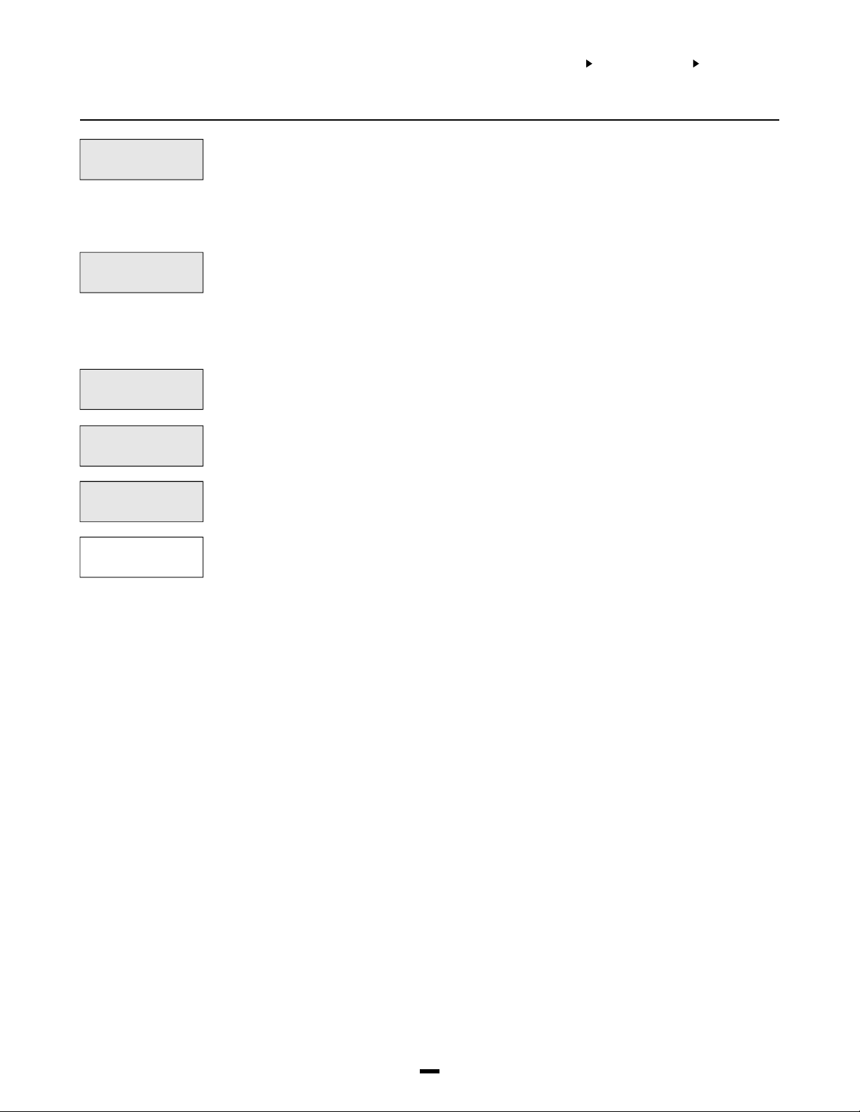
This section contains the Installer’s Code, Grand Master Code, 2nd Grand Master Code, Walk
Test Code and Installer’s Lockout options.
Program Installer’s Code. A new Installer’s Code can be programmed. The default setting is
‘4010’ for 4 digit option, or ‘401000’ for 6 digit option. Enter a new 4 digit code using numbers
from 0 to 9 only. The installer’s code is used to enter [Q][8] Installer’s Programming Commands.
This code should be changed from the default setting before programming is complete to ensure
the security of the system.
Note: If the installer’s code is lost, and installer’s lockout is enabled, there is no way to
enter installer’s programming. The panel will have to return to DSC. Panels returned to DSC
with the installer’s lockout feature enabled and no other apparent problems will be subject
to an additional service charge.
Program Grand Master Code. Master code 001 is the System Grand Master Code. This is the only
code which can program other system master codes. The default setting of this code is ‘1234’ for
4 digit option, or ‘123456’ for 6 digit option. This code should be changed from the default setting
once programming is complete to ensure the security of the system.
The Installer may program a second System Grand Master Code which has the same access as
the System Grand Master Code 001. The Second Master Code is not one of the programmable
128 access codes in [Q][5] programming and therefore cannot be changed by the user. This
code may be used as a Master Key for service and trades people. The default setting of this
code is ‘AAAA’ for 4 digit option, or ‘AAAA00’ for 6 digit option.
PGM Walk Test Code allows access to the Walk Test Mode [Q] [6] [Walk Test Code]. The walk
test mode allows testing of zones that walk test is enabled on.
Each partition to be involved in the walk test must have [Q] [6] [Walk Test Code] entered on one
of its keypads.
INS LOCKOUT OPTS
ENABLE LOCKOUT
DISABLE LOCKOUT
Installer’s Lockout prevents the installer’s code and downloading access code from being
returned to their default values when a hardware or software default occurs.
(4)
Note: Panels returned to DSC with the installer’s lockout feature enabled and no other
apparent problems will be subject to an additional service charge.
Selecting this section will enable Installer’s Lockout and display the message “Ins Lockout
Enabled”.
(0)
Selecting this section will disable Installer’s Lockout and display the message “Ins Lockout
Disabled”.
(1)
4
Page 6

EVENT
MESSAGES
SYSTEM AREA
EVENT MESSAGES
EVENT MESSAGES
(01)
Event messages are two custom messages programmed by the installer. These messages will be
displayed on the keypad when the user fails to arm or an alarm occurs while the system was
armed.
A cursor will appear under the first character of the label. The cursor can be moved to left or right
using the [<][>] keys. The letters of the alphabet have been divided up among the 1-9 number
keys on the keypad.
[1] = A, B, C, 1 [2] = D, E, F, 2 [3] = G, H, I, 3 [4] = J, K, L, 4 [5] = M, N, O, 5
[6] = P, Q, R, 6 [7] = S, T, U, 7 [8] = V, W, X, 8 [9] = Y, Z, 9, 0 [0] = Space
For example, if you press the [4] key, the letter ‘J’ will appear above the cursor on the display.
Press the [4] key again, the letter ‘K’ will appear above the cursor. Press the [4] key a third time
and the letter ‘L’ will appear above the cursor. Press it again and the number ‘4’ will appear on
the display. If a different key is pressed, for example the [6] key, the cursor will automatically
move to the right one space, and the letter ‘P’ will be displayed. To erase a character, move the
cursor under the character using the [<][>] keys, and press the [0] key.
While programming the zone label, press the [Q] key to call up an options menu. To select an
option, either press the corresponding number key, or toggle through the options using the [<][>]
keys and press the [Q] key to select.
[0] Clear Display [1] Clear to End [2] Change Case [3] ASCII Entry (See appendix A)
[4] Save
[0] Clear Display will clear the entire zone label.
[1] Clear to End will clear the display from the character where the cursor was located to the end of
the display.
[2] Change Case will toggle the letter entry between upper case letters (ABC...) and lower case
letters (abc...).
[3] ASCII Entry is for entering uncommon characters. There are 255 characters, but 000 to 031
are not used. Use the [<] [>] keys to toggle through the characters or enter a 3 digit number from
032 to 255. Press the [Q] key to enter the character into the zone label (see Appendix A for the
ASCII characters chart).
[4] Save the label programmed and return to the previous menu.
See [Q][6][Master Code][6] User Functions in the System Manual for enabling these messages
on each partition.
FAIL TO ARM
ALARM WHEN ARMED
SMOKE DETECTOR
WATERFLOW ZONE
The “System Has Failed To Arm” message will appear on every keypad on a partition when a
valid code is entered but the system is unable to arm because a zone is not secure.
(0)
The message will clear after 5 seconds.
This message can be used to remind the user to check all zones and make sure they are secure
before attempting to arm the system.
The “Alarm Occurred While Armed” message appears when a partition is disarmed after an alarm
has occurred. The message will be displayed on all keypads on the partition being disarmed. The
(1)
message will clear after 5 seconds and display the zone(s) that went into alarm.
This message can be used to remind the users of what to do in their situation.
The third message is “Fire Alarm !!! 2 Wire Smoke”, this message will only be displayed if the 2
wire smoke detector on the PC4700 fire module goes into alarm.
(2)
The fourth message is “Fire Alarm !!! Waterflow Sensor”, this message will be displayed if the
waterflow detector on the PC4700 fire module goes into alarm.
(3)
Note: If there is more than one of these fire messages to be displayed at once the messages
will scroll one every three seconds to the next message. Once any fire alarm has been
silenced a message “Fire Bell Has Been Silenced” will be displayed on the partition and
global keypads until the partition is armed.
5
Page 7

SYSTEM AREA
EVENT MESSAGES
SENSOR RESET
UTILITY OUTPUT
This message will be displayed for the sensor reset option in the [Q] menu. This message will
also be displayed when a sensor reset is performed.
(4)
This message will be displayed for the utility output option in the [Q] menu. This message will also
be displayed when a utility output is performed.
(5)
Notes: Since editing this label will affect how the Utility Output and Sensor Reset labels appear on all partitions if
the outputs perform different functions on different partitions the labels should be left at default.
The logs to the viewable and printed event buffer will not use the programmable label. They will continue to log as
“Utility Output” and “Sensor Reset”.
ZONE TAMPER
ZONE FAULT
The “Zone Tamper” message will appear on every partition keypad when a zone using double EOL
is put into the tamper condition (zone open). The message is displayed while viewing open zones.
(6)
The “Zone Fault” message will appear on every partition keypad when a zone using double EOL is
put into the fault condition (zone shorted). The message is displayed while viewing open zones.
(7)
Note: Zone Tamper and Zone Fault sections will only appear when double EOL is being used.
6
Page 8

SYSTEM
OPTIONS
SYSTEM AREA
SYSTEM OPTIONS
SYS TOGGLE OPT
SYSTEM OPTIONS
(02)
This section contains options that are relevant to the entire system. System Toggle options,
Keypad Toggle options, Keypad Lockout options and System Time can all be programmed in this
section.
Sys Toggle Options
SYS TOGGLE OPT
CHANGE SYS MAS
POWER UP SHUNT
AC TBL DISP
60 Hz LINE
Toggle options are in question form. Use the [Q] key to toggle between Yes and No to enable or
disable the feature. Use the [<] [>] keys to scroll through the options.
(0)
Changeable System Grand Master Code?
YES = System Grand Master Code can be changed by the end user via Grand Master Code.
Y
NO = The System Grand Master Code can only be changed via installer’s programming.
Shunt Zones on Power Up?
YES = All zones are considered non-violated by the main control for the first 2 minutes that
Y
NO = The zones are active upon power up.
AC Trouble Displayed?
YES = The system will monitor and display an incoming AC power failure from the transformer.
Y
NO = The system will not display the incoming AC power failures.
Is the incoming AC Frequency 60 Hz?
YES = The incoming AC power from the transformer cycles at 60 Hz. The North American
Y
NO = The incoming AC power cycles at 50 Hz.
power has been applied to the system. This will allow time for the detectors to “settle”
without causing false alarms.
standard is 60 Hz.
FOR FUTURE USE
AC INHIBIT ARM
DC INHIBIT ARM
N
AC inhibits arming?
YES = When an AC trouble condition is present on the main panel or PC4204, the system cannot be
N
armed, except by autoarm.
NO = Regardless of the presence of an AC Trouble, the system can be armed.
DC inhibits arming?
YES = When a low battery condition is present on the main control panel or on a PC4204
N
expansion module, the system can not be armed (DC Inhibit Arm does not apply to
wireless zone that have battery troubles). If the partition is attempted to be armed the
keypad display will show the message “Fail To Arm... DC Trouble”. When an access code
is entered the panel will perform a battery check on the main control panel and on each of
the PC4204’s enrolled on the system. This will ensure that the battery condition is good
before the panel is armed. If the control panel has a battery trouble or any one of the
PC4204’s report back with a battery trouble the arming will be aborted.
No = No forced battery check will be performed and a Battery trouble will not inhibit arming.
Note: The Control panel and each of the PC4204 modules may only have 3 battery trouble
alarms in a 24 hour period. After the third battery trouble for a given module the trouble
condition will “Shutdown” until midnight of that day. The trouble will still be enunciated
with the keypad Trouble LED but the event will not be logged to the event buffer or be
communicated.
7
Page 9

MEMORY DISP
Memory displayed?
YES = When the partition is armed, any zones have gone into alarm can be viewed by pressing
N
the [<] [>] keys.
NO = Show memory after disarming only.
BYPASS DISP
BELL SHUT DOWN
FOLLOWS + ALARMS
6 DIGIT CODES
Bypass displayed?
YES = When the partition is armed, bypassed zones can be viewed by pressing the [<][>] keys.
N
NO = Shows bypassed zones when disarmed only, by pressing [Q][1].
Bell shut down?
YES = The bell output will no longer activate for a zone that has reached the swinger shut down
Y
threshold. (See ‘Swinger Limit’ and ‘Swgr Shut Down’.)
NO = Every time a zone is violated it will reactivate the bell output.
Follows includes alarms?
YES = Enables all outputs programmed to follow zones (Zone Follow, Zn Tamp Follow and Zn
N
Fault Follow), including PC4216s programmed as ‘Follow XX-XX‘, to also annunciate
alarms when those zones are armed.
When the zone is disarmed the output will follow the zone status. When the zone is
violated the output will activate. When the zone is restored the output will deactivate.
When the zone is armed the output indicates alarm status. The output is not activated
until the zone is violated and then remains active. When the zone is disarmed the
output remains active to indicate which zone caused the alarm. To get the output to
follow the zone status the partition must be armed and disarmed.
NO = Disables the ability to latch alarm status. The output follows zone activity whether armed
or disarmed.
Six digit access codes?
YES = All access codes on the system will need to be 6 digits in length except Panel ID code
N
and DLS access code.
NO = Regular 4 digit codes to be used.
HOURLY PRINT
MILITARY TIME
KEYPAD TAMPERS
GLOB [F] ENAB
GLOB [A] ENAB
Hourly printer test?
YES = Panel will print a line saying ‘Hourly Printer Test’ with time and date every hour.
N
NO = Panel will not log “Hourly Printer Test”.
Military time?
YES = Clock will show in 24 hour time (military time) and date will show as Month/Day/Year (MM/
N
DD/YY). For example, 1:30 pm December 13, 1994 will be displayed as 12/13/94 13:30.
NO = Clock will show in 12 hour time with an ‘a’ for am or ‘p’ for pm, and date will show as
Month/Day/Year (Mon/DD/YY). For example, 3:30 pm January 5, 1994 will be displayed as
Jan 05/94 3:30 p.
Keypad tampers?
YES = Keypad Tampers are used. This option should be enabled only if keypad tamper plates
N
are attached to the keypad.
NO = Keypad Tampers are disabled.
Global keypad [F] key enabled?
YES = The [F] key is enabled for global keypads.
Y
NO = The [F] key is disabled for global keypads.
Global keypad [A] key enabled?
YES = The [A] key is enabled for global keypads.
Y
NO = The [A] key is disabled for global keypads.
8
Page 10

SYSTEM AREA
SYSTEM OPTIONS
SYS TOGGLE OPT
GLOB [P] ENAB
GLOB DISP CLK
GLOB KEYPAD LOCK
KYPAD #1 GLOBAL
TAMPER INHIBIT
Global keypad [P] key enabled?
YES = The [P] key is enabled for global keypads.
Y
NO = The [P] key is disabled for global keypads.
Global keypad displays clock?
YES = The time and date will be displayed on global keypads instead of the “Enter Your Access
Y
Code” message after 10 seconds of no key presses.
NO = No clock display.
Global keypad lookout?
YES = Keypad Lockout is enabled on global keypads.
N
NO = Keypad Lockout is disabled on global keypads.
(See “Total Bad Codes”, “Lockout Duration” and “Lockout Rep Code”.)
Keypad #1 global?
YES = Keypad #1 becomes a global keypad.
N
(See System Manual, Book 1 for further details about “Global Keypads”.)
NO = Keypad #1 is not a global keypad.
Notes: Entry/Exit Delay with Urgency will always be present on a global keypad (See
“Partition Toggles”).
If a keypad is loaned to a deleted partition once Installer’s Mode is exited, the keypad will be
reassigned to the lowest assigned partition.
Tamper inhibits arming?
YES = A Zone Tamper requires the Installer’s Code entry before the partition can be armed or the
N
Zone Trouble Restoral Code sent.
NO = Zone Tamper Restorals will follow the zone.
TROB REQ CODE
UL COMMERCIAL
RF TMP DISARM
Troubles require code?
YES = A valid access code will be required to silence the trouble beeps from the keypad (or the
N
trouble condition must be restored. When the code is entered 3 quick acknowledgment
beeps will be heard from the keypad and the trouble beeps will not restart until a new
trouble condition occurs.
NO = No access code is required to silence trouble beeps. Any keypress or the trouble
condition restoring will silence the trouble beeps.
YES = The following UL options are enabled when this toggle option is enabled: (1) Any Fire alarm will
N
require an access code to be restored. The zone will show open even once the zone has been
restored ([Q][4] sensor Reset) until an access code has been entered. When a code has been
entered to reset the fire zones the keypads for that partition will display the message “Fire
Zones Were Reset”. (2) DLS Fault - This trouble condition will generate an audible and visual
trouble when the control panel fails to complete communications with the downloading
computer. (3) When a Module Com Fault occurs all Burglary outputs will squawk every 5
seconds (included are fire/burg, invert fire/burg, burg. and invert burg) for the partition(s).
Pressing a key on the partition will silence the output squawks.
NO = An access code is not required to restore the fire zones
RF zone tamper while disarmed?
YES = RF Zones will always cause tamper alarm(s) and transmissions
Y
NO = When this option is turned off and the partition is disarmed. RF tampers will create a
trouble condition “RF Zn Tamper TBL”. The Trouble LED will activate and the partition
keypad will begin trouble beeps every 10 seconds. While the partition is disarmed the
zone tamper will be logged to the event buffer but no Tamper alarm transmission will
occur. The event is logged and transmitted while the partition is armed. This is done so
that while the user is changing batteries in a Wireless Zone no tamper alarm will be sent.
9
Page 11

SYSTEM AREA
SYSTEM OPTIONS
SYS TOGGLE OPT
SYS.FLT.SQUAWK
CD DISP INHIBIT
GLOB ALM ANNUN
GLB KYPD TRB
System Fault Squawk
Yes = Causing a Zone tamper, zone fault or a Module tamper will cause all Burglary outputs to
N
squawk every 5 seconds (included are fire/burg, invert fire/burg, burg. and invert burg) for
the partition(s). The “Squawks” will be silenced when the alarm is silenced or a key is
pressed on that partition. By default this option is set to No.
No = Zone Tampers, Faults and Module Tampers will not squawk the burglary outputs.
Code Display Inhibited
Yes = When programming Access codes ([*][5] Access code Programming) the code numbers
N
will be X’d out ([XXXX] or [XXXXX] if using 6 digit access codes). By default this option is
set to No.
No = The digits of the access code will be displayed •as entered on the keypad being used for
programming.
Global Alarm Annunciation
Yes = This system toggle will allow the Global keypads to sound the buzzer (5 seconds on and 5
N
seconds off) and display the message “Partition X In Alarm” (where Partition X is the
programmed label of the partition) when any other partition is in alarm. The buzzer will be
silenced and the message cleared from the keypad display when the alarm has been
silenced or any key is pressed on the keypad. By default this option is set to No.
No = No notification of the alarm will be given on the Global Keypad.
Note: It is recommended that global alarm annunciation is enabled on multi partition systems.
Global Keypad Trouble
Yes = Troubles present on the system can be viewed from global keypads. If a trouble is present
Y
on the system, the user will be prompt with the option to view system troubles.
No = Troubles can not be viewed from global keypads. The keypad must be loaned to a partition
before troubles can be viewed.
GLB KYPD STAT
GLB KP ALL ENT
Global Keypad Partition Status Enunciator
Yes = Enables the Partition Status Enunciator on global keypads. Global keypads will display the
N
status of all active partitions on the system.
No = Global keypads will not display the Partition Status Enunciator.
Note: This option overrides the clock display option.
Global Keypad Enunciates All Entry Delays
Yes = The entry delay for any Partition will be enunciated on Global Keypads.
N
No = All Partitions must be armed before entry delay will be enunciated on Global Keypads.
10
Page 12

SYSTEM AREA
Keypad Toggle Options
KEYPAD TOG OPT
Programming the operation of the 3 keypad emergency keys ([F], [A] and [P]). Toggle options are
in the form of questions. Use the [Q] key to toggle between Yes and No to enable or disable the
(1)
feature. Use the [<][>] keys to scroll through the options. Regardless of programming each key
must be pressed for 2 seconds before the alarm will be activated.
SYSTEM OPTIONS
KEYPAD TOG OP T/KYPD LOCKOUT OP T/SYSTEM TIMES
[F] BELL
[F] PULSE BELL
[F] BUZZER
[A] SIL BELL
[A] STDY BELL
[F] key activates the Bell Outputs?
YES = The bell output will activate when the [F] key is pressed.
Y
NO = The bell output will not activate when the [F] key is pressed.
The bell output for the [F] key is any output (Bell, SW Aux or PGM) that is programmed for Fire
and Burg, Inv Fire and Burg, Fire Only and Inv Fire Only.
[F] key pulses the Bell Output?
YES = The bell output, if enabled, will pulse when the [F] key is pressed.
Y
NO = The bell output, if enabled, will be steady when the [F] key is pressed.
The bell output for the [F] key is any output (Bell, SW Aux or PGM) that is programmed for Fire
and Burg, Inv Fire and Burg, Fire Only and Inv Fire Only.
The keypad beeps when the [F] key is pressed?
YES = The keypad will beep 3 times when the [F] key has been pressed for 2 seconds.
Y
NO = The keypad will not sound when the [F] key is pressed.
The bell is silent when the [A] key is pressed?
YES = The bell output will not activate when the [A] key is pressed.
Y
NO = The bell output will activate when the [A] key is pressed.
The bell output for the [A] key is any output (Bell, SW Aux or PGM) that is programmed for Fire
and Burg, Inv Fire and Burg, Burg Only and Inv Burg Only.
The bell is steady when the [A] key is pressed?
YES = The bell output, if enabled, will be steady when the [A] key is pressed.
Y
NO = The bell output, if enabled, will pulse when the [A] key is pressed.
The bell output for the [A] key is any output (Bell, SW Aux or PGM) that is programmed for Fire
and Burg, Inv Fire and Burg, Burg Only and Inv Burg Only.
[A] AUD BUZZ
[P] SIL BELL
[P] STDY BELL
[P] SILENT BUZ
The keypad beeps when the [A] key is pressed?
YES = The keypad will beep 3 times when the [A] key has been pressed for 2 seconds.
N
NO = The keypad will not sound when the [A] key is pressed.
[P] key activates the Bell Outputs?
YES = The bell output will not activate when the [P] key is pressed.
Y
NO = The bell output will activate when the [P] key is pressed.
The bell output for the [P] key is any output (Bell, SW Aux or PGM) that is programmed for Fire
and Burg, Inv Fire and Burg, Burg Only and Inv Burg Only.
The bell is steady when the [P] key is pressed?
YES = The bell output, if enabled, will be steady when the [P] key is pressed.
Y
NO = The bell output, if enabled, will pulse when the [P] key is pressed.
The bell output for the [P] key is any output (Bell, SW Aux or PGM) that is programmed for Fire
and Burg, Inv Fire and Burg, Burg Only and Inv Burg Only.
The keypad does not beep when the [P] key is pressed?
YES = The keypad will not sound when the [P] key is pressed.
Y
NO = The keypad will beep 3 times when the [P] key has been pressed for 2 seconds.
11
Page 13

SYSTEM AREA
Keypad Lockout Options
KYPD LOCKOUT OPT
TOTAL BAD CODES
LOCKOUT DURATION
Keypad Lockout Options
This section contains programming for the keypad lockout feature. After a programmed number
(2)
of incorrect attempts to enter an access or installer’s code the keypad will lockout, preventing the
user from performing any function. A message “Keypad Lockout is Active” will be displayed for
the lockout duration. See “KYPD LOCKOUT” under “PAR TOGGLES” to enable the keypad
lockout feature on a partition.
Enter the number of incorrect code entries (from 000 to 255) required to activate keypad lockout
if the option is enabled. See “PAR TOGGLES”, “KYPD LOCKOUT” to enable the keypad lockout
(0)
feature on a partition. The default setting is 005.
This section determines the number of minutes the keypad lockout will remain active for. Enter the
duration of the keypad lockout. Valid entries are from 000 to 255. The default setting is 015.
(1)
System Times
SYSTEM TIMES
They are system times relevant to the whole system.
(3)
SYSTEM OPTIONS
KEYPAD TOG OP T/KYPD LOCKOUT OP T/SYSTEM TIMES
ZONE RESPONSE
(0)
BELL CUTOFF
(1)
POLICE CODE TIME
(2)
KEYPAD TIMEOUT
(3)
Zone Supervision
ZONE SUPERVISION
(4)
NO EOL
SINGLE EOL
DOUBLE EOL
The zone loop response time is the length of time (005 - 255 x 100 ms) a zone must be violated
before it is detected. (100 ms = one tenth of a second.) Minimum zone loop response time is 500
ms. The factory default setting is 005 (500 ms).
Program the amount of time (from 000 to 255 minutes) the bell output will activate when an alarm occurs.
The factory default setting is 004 (4 minutes). Bell Cutoff is for any output (Bell, SW Aux or PGM) that is
programmed for Fire and Burg, Inv Fire and Burg, Burg Only, Inv Burg Only, Fire Only, and Inv Fire Only.
Program the amount of time (000 - 255 Minutes) before a Police Code Alarm reporting code will
be sent to the monitoring station. A Police Code Alarm is sent when 2 zone alarms occur within
the programmed time. Default is 060 minutes.
Whenever a keypad is loaned to another partition, the keypad will return to it’s home partition
after the programmed amount of time. (000 - 255 seconds) default = 20 seconds.
The zone is a normally closed loop to ground. The zone will be violated when it is open.
All zones must have a 5600 ohm resistor across them. If the zone is shorted or open, it will be in a
violated condition. If the zone is open and programmed as a fire zone, it will be in a trouble
condition. See “[Q][2] Trouble Display”.
Notes: If zones are programmed for Fire or Links Supervisory, EOL resistors must be used.
This configuration will allow the panel to detect zone Faults (zone shorted), zone tampers (open
circuit), open zones (Alarm condition of the 11200 Ohms) and restored zones. If the zone is
disarmed and placed in the Tamper (open) or Fault (Short) state the keypad buzzer will sound
from all partition keypads (that the zone belongs to) for the length of bell time out or until an
access code is entered. A zone tamper (or Fault) alarm reporting code will be sent to the
monitoring station if programmed. When the partition is armed and a zone is Tampered or Faulted
all burglary outputs for the partition will activate for the length of bell time out or a valid access
code is entered. There will be no buzzer sounded while the zone is armed. A zone tamper (or
Fault) alarm reporting code and zone alarm reporting code will be sent to the monitoring station if
programmed. See Reporting Codes for details. Refer to the System Manual for detail on the
hookup procedure. All zones on the PC4010 can use double EOL resistors, except wireless
zones (Zone that belong to the PC4164), Fire Zones all types (Standard Fire, Delay Fire, Auto
Verify Fire, Sprinkler PC4700 2 Wire Smoke and Waterflow), Links Supervisory, Links Answer and
Forced Answer zones. These zone types must only be used with single EOL. double EOL
resistors allow the zone to be capable of detecting zone tampers and zone faults. The Tamper
resistor (5600 Ohms) is placed across the alarm contact, and the single EOL resistor (5600
Ohms) is placed between the alarm contact and the tamper contact.
12
Page 14

DOWNLOAD
SECTION
SYSTEM AREA
DLS SECTION
DLS TOGGLE S/DLS OPTION S/DLS REPORT CODES
DLS SECTION
(03)
This section will allow you to program all options related to downloading.
Download Toggles
DLS TOGGLES
DLS ENABLE
USER CALL UP
DOUBLE CALL
Downloading Toggle Options. Toggle options are in the form of questions. Use the [Q] key to
toggle between Yes and No to enable or disable the feature. Use the [<][>] keys to scroll through
(0)
the options.
Downloading Enable?
YES = The panel will answer after the programmed number of rings.
N
NO = DLS Enable disabled. The only way downloading can occur is by using either the
User Call Up?
YES = The user can cause the panel to call a remote computer by entering the [Q][6][Master
N
NO = The feature is disabled.
Double Call?
YES = If the panel detects 1 or 2 rings on the first call and then is called again within a variable
N
NO = The panel will only answer after the programmed number of rings is reached. See “# OF
“USER CALL UP” feature or the “PERIODIC CALLUP” feature. DLS Enable can be
turned on by the end user for 60 minutes if the “USER ENABLE DLS” option is enabled.
Code][7] user callup command. (See also “PHONE NUMBER” and “PANEL ID CODE” in
the DLS options.)
time of 000 to 255 seconds (programmable - see “2 CALL TIMER”), the panel will
answer the second call on the first ring. This is useful for bypassing an answering
machine on the same line as the panel.
RINGS”.
DLS CALLBACK
PERIODIC DLS
USER ENABS DLS
Downloading Call Back?
YES = Callback is enabled. After connection to the panel both the computer and the panel will
N
hang up. The computer will then wait for the panel to call. If there is more than one
downloading computer, callback should be disabled.
NO = Callback is disabled. The downloading computer will have immediate access to the
control panel once accepted as valid.
Periodic Downloading?
YES = Periodic Downloading is enabled. Periodic downloading is used to allow the computer
N
to execute batch files. The computer must be waiting for a call for this feature to be
useable. See “Periodic Callup” for programming the time of day and the number of
days in between periodic downloads.
NO = Periodic Downloading disabled.
User Enables Downloading?
YES = The end user may enable ring detect for 60 minutes to allow a computer to access the
Y
control panel. If the “DLS ENABLE” option has been enabled, this option is overridden.
NO = Option disabled.
13
Page 15

DLS Options
SYSTEM AREA
DLS SECTION
DLS TOGGLE S/DLS OPTION S/DLS REPORT CODES
PERIODIC CALLUP
SET CYCLE DAYS
SET 24HR TIME
PHONE NUMBER
PANEL ID CODE
ACCESS CODE
2 CALL TIMER
Programming the time and number of days between periodic downloads. (See “Periodic DLS” for
enabling Periodic Downloading.)
(1)
Set Downloading Cycle Days?
Program the number of days (from 001 to 255 days) between periodic downloads. The default
(0)
setting is 030.
Set 24 Hour Time?
Program, in military time, the time of day the panel will call the computer for periodic
(1)
downloading. The default setting is 0000.
Downloading Phone Number?
Enter the telephone number for computer if User Call Up, Periodic DLS, or DLS Callback is
(2)
enabled. See “PGM TEL NUMBER” for entering a telephone number and options when
programming the phone number.
Panel Identifier Code?
This four digit code will allow the computer to identify the panel that is calling. It must be
(3)
programmed differently for every panel if User Call Up, Periodic DLS or DLS Callback is used.
The default setting is 4911.
Panel Downloading Access Code?
This 4 digit code must be programmed the same as the computers. If the code is different the
(4)
panel will NOT allow any uploading or downloading to take place. It is used to help ensure the
security of the system. The default setting is 4910.
Double Call Timer?
This is the maximum allowable time in seconds between two phone calls when the “Double Call”
(5)
option has been enabled. Valid entries are between 000 and 255 seconds. The default setting is
060. (See “Double Call” for enabling the double call feature.)
# OF RINGS
Number of Rings?
This is the number of consecutive rings the panel must detect before answering the call. (See
(6)
“DLS Enable” or “User Enabs DLS” for enabling DLS Enable.) Valid entries are between 001 and
255 rings. The default setting is 008.
14
Page 16
COMMUNICATOR
SECTION
SYSTEM AREA
COMMUNICATOR
MAIN ITEMS
COMMUNICATOR
(04)
All options concerning communications can be programmed, including phone numbers,
reporting codes, account numbers and communicator options.
Main Items - Phone Numbers/Communication Format/Dialer Direction
MAIN ITEMS
The PC4010 can call up to 3 different phone numbers when reporting any event to a monitoring station. The second and
third numbers can be used as backups if the first or second fail.
Note: Dial Tone Search must be included for a number to backup to its Links Number.
1ST NUMBER
2ND NUMBER
3RD NUMBER
PGM TEL NUMBER
Handling the phone numbers of monitoring stations or remote areas the panel communicates with.
(0)
1st Number can report any event program set in the dialer directions. By default all events are
sent through the first phone number. See ‘Communicator Toggles’ for more detail on backups.
(0)
2nd Number can report any events programmed if set in the dialer directions and can back up
the 1st Number. See ‘Communicator Toggles’ for more detail on backups.
(1)
3rd Number can report any events programmed if set in the dialer directions. It can also be used
to back up the first and/or second phone number. See ‘Communicator Toggles’ for more detail on
(2)
backups.
Enter the communicator telephone number the way you would dial it on a telephone. The total
number of digits including dial tone searches and pauses must not exceed 31. Press the [Q] key
(0)
to enter the telephone entry options menu. A ‘D’ for dial tone search is already programmed as the
first digit.
[0] Save [1] Dial tone [2] Pause 2 Seconds [3] Pause 4 Seconds
[4] DTMF [Q] [5] DTMF [#] [6] Previous Menu
[0] Save can be selected for the telephone number to be stored into the panel’s memory, or
simply press [#] when finished entering the phone number.
[1] Dial tone will add a dial tone search to the telephone number, which will be represented by a
‘D’ on the display. When the panel does a dial tone search, it looks for dial tone before
dialing the programmed telephone number.
[2] Pause 2 Seconds will add a two second pause to the dialing sequence, which will be
represented by the letter ‘A’ on the display.
[3] Pause 4 Seconds will add a four second pause to the dialing sequence, which will be
represented by the letter ‘E’ on the display.
[4] DTMF [Q] will input an asterisk, represented by a ‘B’ on the display. The dialer will output the
same frequencies as a touch tone phone would if the [Q] key were pressed. (Frequently
required to disable call waiting.)
[5] DTMF [#] will add a ‘#’ to the telephone number, represented by the letter ‘C’ on the display.
The dialer will output the same frequencies as a touch tone phone when the ‘#’ key is
pressed. (In some instances it is used to disable call waiting.)
15
Page 17

SYSTEM AREA
COMMUNICATOR
MAIN ITEMS
COMMS FORMAT
There are 19 formats in the PC4010 for communicating with the monitoring station. The system
must be programmed to use the same communications format as the receiver at the monitoring
(1)
station. The default format is (01).
(00) 10 Bps 1400 - Silent Knight, Ademco Slow
(01) 20 Bps 2300 - Sescoa, Franklin, DCI, Vertex
(02) 20 Bps 1400 - Silent Knight Fast
(03) 40 Bps 2300 - Radionics
(04) 40 Bps 1400 - Radionics
(05) 40 Bps 2300 P - Radionics with Parity
(06) 40 Bps 1400 P - Radionics with Parity
(07) 10 Bps 1400 X - Silent Knight, Ademco Slow extended
(08) 20 Bps 2300 X - Sescoa, Franklin, DCI, Vertex extended
(09) 20 Bps 1400 X - Silent Knight, Ademco Fast extended
(10) 40 Bps 2300 X - Radionics Extended
(11) 40 Bps 1400 X - Radionics Extended
(12) 40 Bps 2300 XP - Radionics Extended with Parity
(13) 40 Bps 1400 XP - Radionics Extended with Parity
(14) SIA Fsk Format
(15) Sescoa Super Speed
(16) Sescoa Super Speed ID
(17) DTMF Contact ID
(18) 4/3 DTMF Format - Surgard
(19) Pager 1
(20) Pager 2
(21) Pager 3
Communications Compatibility
All these communication formats are compatible with the Silent Knight SK9000 and Ademco
model 685 receivers with the exception of formats (15), (16), (17) and (18). Formats (15) and (16)
are compatible with the Linear/Sescoa model 3000C receiver.
10, 20 and 40 BPS Formats
10 Bits Per Second is the standard slow format used on Silent Knight and Ademco receivers.
Data = 1900 Hz Kissoff = 1400 Hz Speed = 10 Baud
20 Bits Per Second is the standard fast format used on DCI, Franklin, Sescoa and Vertex
receivers.
Data = 1800 Hz Kissoff = 1400/2300 Hz Speed = 20 Baud
40 Bits Per Second is the standard format used on Radionics receivers.
Data = 1800 Hz Kissoff = 1400/2300 Hz Speed = 40 Baud
These formats will send an account code to identify which customer is sending the alarm, and a
reporting code to identify the type of alarm. Depending on the receiver, the account code must be
either 3 or 4 digits, and the reporting code must be either 1 or 2 digits. If the account code needs
to be only 3 digits, program the ‘System ID Code’ and each partition’s ‘Customer ID Code’ with 3
digits, followed by a ‘0’. If you wish to send a zero in the account code, program it with a HEX A.
For example, if you wish to send 103 as your account code, program the System or Customer ID
code with ‘1A30’. If the reporting code needs to only be 1 digit, program the reporting codes with
one digit followed by a ‘0’. For example, to send a ‘3’, program ‘30’ into the reporting codes. To
send a zero, program HEX A into the reporting code. For example, to send 30, enter 3A.
16
Page 18

SYSTEM AREA
COMMUNICATOR
MAIN ITEMS
Radionics Format
For conventional 3/1 Radionics format the communications mode should be set to either (10) or
(11), the 40 Bps extended format. The following guidelines have been provided to help in
configuring the PC4010 for Radionics format.
1. The system ID code and customer ID codes must be only 3 digits with a zero making up
the 4th digit (i.e. program 1230 for ID code 123.)
2. The zone alarm reporting codes must all be single digit numerical codes with no extended
2nd round being sent. The zero in the 2nd digit of the reporting code tells the PC4010 not to
send an extended code.
3. All other non-alarm reporting codes must be set up to send an extended 2nd round. The
1st digit of the reporting code is used to identify the event while the 2nd or extended digit is
used to associate the event with a particular item. (i.e. A reporting code of E3 means
restore zone 3 - E for restore and 3 for zone 3.)
4. The following is a list of 1st digit identifiers that should be used with the Radionics format.
Restorals “E” Example “E3” = Restore zone 3
Openings “B” Example “B2” = Opening by User 2
Closings “C” Example “C4” = Closing by User 4
Troubles “F” Example “F5” = Trouble from Source 5
Misc “D” Example “D1” = Partial Closing
Alarm “A” Example “A7” = Alarm Zone 7
SIA 1986 Format
The system ID codes and the customer ID codes must be four decimal digits in length. The
reporting codes must be 2 digits.
Note: Do not program the keypad lockout reporting code or the printer buffer nearly full
reporting code.
The SIA format will transmit a 4 digit account code, a 2 digit identifier code and a 2 digit reporting
code. The 2 digit identifier is preprogrammed by the PC4010. The 2 digit reporting code is
programmed by the installer with any hex number from 01 to FE.
Preprogrammed
Identifiers
2 Wire Smoke Alarm FA
2 Wire Smoke Trouble FS
2 Wire Smoke Alarm Restore FR
2 Wire Smoke Trouble Restore FR
2nd Master Close CL
2nd Master Open OP
4204 AC Trouble Restore AR
4204 Aux Supply Trouble Restore UR
4204 Battery Trouble Restore YR
4204 Battery Trouble Alarm YT
4204 Aux Supply Trouble Alarm UT
4204 AC Trouble Alarm AT
Auto Arm Abort CE
Automatic Arming Closing CA
Cellular Trouble LT
Cellular Trouble Restoral LR
Closing Access Codes 1 to 128 CL
Closing Keyswitch CL
COMBUS Trouble Alarm UT
COMBUS Trouble Restoral UR
Downloading Lead In RB
Downloading Lead Out RS
Duress HA
Ground Fault Restore UR
Ground Fault US
DVAC Trouble YS
DVAC Trouble Restore YK
Hold Up Alarm HA
Hold Up Restore HR
Installer’s Lead In LB
Installer’s Lead Out LS
Keypad Lockout DC
Keypad [F] Key Alarm FA
Keypad [A] Key Alarm MA
Keypad [P] Key Alarm PA
Keypad [F] Key Restore FR
Keypad [A] Key Restore MR
Keypad [P] Key Restore PR
Links Test RP
Module Tamper Restoral TR
Module Tamper Alarm TA
Opening After Alarm OR
Opening Access Codes 1 to 128 OP
Opening Keyswitch OP
Opening Automatic OA
Panic Alarm PA
Panic Restoral PR
Partial Closing Code CG
Partition Close CL
Partition Open OP
Periodic Test UL RP
Periodic Test RP
Police Restore BR
Police Alarm BA
Printer Buffer Nearly Full JL
Quick Arm Closing Code CL
Preprogrammed
Identifiers
17
Page 19

SYSTEM AREA
COMMUNICATOR
MAIN ITEMS
RS-232 Trouble VT
RS-232 Restore VR
Sprinkler Zone Trouble ST
Sprinkler Zone Trouble Restore SR
Sprinkler Zone Alarm SA
Sprinkler Zone Restore SR
System TLM Restore Line 2 LR
System TLM Trouble LT
System Bell Trouble Alarm UT
System AC Trouble Alarm AT
System Battery Trouble Alarm YT
System TLM Trouble Line 2 LT
System FTC Restoral UR
System TLM Restoral LR
System AUX Supply Trouble Alarm UT
System Test RX
System AC Trouble Restoral AR
System Aux Supply Trouble Restoral UR
System Battery Trouble Restoral YR
System Bell Trouble Restoral UR
Technical Alarm UA
Technical Restore UR
Waterflow Trouble Restore SR
Waterflow Alarm SA
Waterflow Alarm Restore SR
Waterflow Trouble SS
Automation Fault ET
Automation Restore ER
Zone Alarms 1 to 128 - Fire FA
Zone Alarms 1 to 128 - All others BA
Zone Sensor Fault ET
Zone Low Bat Alarm XT
Zone Sensor Fault ET
Zone Low Bat Restore XR
Zone Troubles 1 to 128 - Fire FT
Zone Fault Restore TR
Zone Tamper 1 to 128 TA
Zone Fault TA
Zone Sensor Fault Restore ER
Zone Restorals 1 to 128 - All others BR
Zone Restorals 1 to 128 - Fire FR
Zone Tamper Restorals TR
Sescoa Super speed and Sescoa Super Speed ID
The system ID code and customer ID codes must be four decimal digits in length and in the range
of 0001 to 3374.
The reporting codes must be 2 digits in length and programmed as follows. All zero’s must be
replaced with ‘A’s. For example, to send 20, the PC4010 must be programmed with a 2A. (To
disable a reporting code, leave as FF.)
Notes: Do not program the Downloading Lead In reporting code, the Downloading Lead Out
reporting code, the Installer’s Lead In reporting code, the Installer’s Lead Out Reporting Code,
the RS-232 Trouble Alarm Rep Code or the RS-232 Trouble Restoral Rep Code.
The keyswitch zones will be identified as the zone number plus 128. For example, if the
closing user zone and the closing keyswitch zone numbers are both 002, the closing
keyswitch zone will then be identified as 130 (zone number 2 + 128 = 130).
Program different reporting codes for zone tamper and zone alarm for identifying a zone
tamper from a zone alarm.
Code
2 Wire Smoke Alarm Trouble A1 to 9A
2 Wire Smoke Alarm Restore A1 to 9A
2 Wire Smoke Alarm A1 to 9A
2 Wire Smoke Alarm Trouble Restore A1 to 9A
2nd Master Close CA
2nd Master Open BA
4204 Battery Trouble Restore E1
4204 Aux Supply Trouble Restore A1 to 9A
4204 AC Trouble Alarm E1
4204 Battery Trouble Alarm E1
4204 Aux Supply Trouble Alarm A1 to 9A
4204 AC Trouble Restore E1
Auto Arm Abort C1
Automatic Closing CA
Automatic Opening BA
Buffer Near Full A1 to 9A
Cellular Trouble Restoral EE
Cellular Trouble EE
Closing Reporting Codes 1 to 128 CA
COMBUS Trouble Restore A1 to 9A
COMBUS Trouble Alarm A1 to 9A
DVAC Trouble EE
DVAC Trouble Restore EE
Duress D1
Ground Fault A1 to 9A
Hold Up Restore A1 to 9A
Hold Up Alarm A1 to 9A
Keypad [P] key Restoral A1 to 9A
Keypad [F] key Alarm A1 to 9A
Keypad Lockout Code A1 to 9A
Keypad [F] key Restoral A1 to 9A
Keypad [A] key Restoral A1 to 9A
Keypad [A] key Alarm A1 to 9A
Keypad [P] key Alarm A1 to 9A
Keyswitch Opening BA
Keyswitch Closing CA
Links Test 1C
Module Tamper Restorals A1 to 9A
Module Tamper Alarms A1 to 9A
Opening After Alarm Code BA
Opening Reporting Code 1 to 128 BA
Panic Alarm A1 to 9A
Code
18
Page 20

SYSTEM AREA
COMMUNICATOR
MAIN ITEMS
Code
Panic Restore A1 to 9A
Partial Closing Code C1
Partition Open BA
Partition Close CA
Periodic Test 1C
Periodic UL Test 1C
Police Restore A1 to 9A
Police Alarm A1 to 9A
Quick Arm Closing Code CA
RS-232 Trouble A1 to 9A
RS-232 Restoral A1 to 9A
System Aux Supply Trouble Alarm A1 to 9A
System Bell Trouble Restoral F1
System TLM Line 2 Restoral EE
System Battery Trouble Alarm E1
System AC Trouble Alarm E1
System Battery Trouble Restoral E1
System AC Trouble Restoral E1
System Aux Supply Trouble Restoral A1 to 9A
System Bell Trouble Alarm F1
System TLM Line 1 Restoral EE
System TLM Line 2 Trouble EE
System Test 1C
System FTC Restoral EE
Technical Alarm A1 to 9A
Technical Restore A1 to 9A
Waterflow Alarm Trouble Restore A1 to 9A
Waterflow Alarm A1 to 9A
Waterflow Alarm Restore A1 to 9A
Waterflow Alarm Trouble A1 to 9A
Automation Restore A1 to 9A
Automation Fault A1 to 9A
Zone Sensor Fault Restore A1 to 9A
Zone Low Battery E1
Zone Sensor Fault A1 to 9A
Zone Fault 1 to 128 A1 to 9A
Zone Fault Restore 1 to 128 A1 to 9A
Zone Low Battery Restore E1
Zone Alarms 1 to 128 A1 to 9A
Zone Trb./Tamp Restoral 1 to 128 A1 to 9A
Zone Restoral 1 to 128 A1 to 9A
Zone Trb./Tamp 1 to 128 A1 to 9A
Code
System TLM Line 1 Trouble EE
Contact ID
The System ID code and 4 Customer ID codes must be 4 decimal digits. The reporting codes must
be 2 digits and programmed as follows.
Note: Do not program the Opening After Alarm, Buffer Nearly Full, Installer Lead In and
Installer Lead Out reporting codes.
Do not use this format with 1300 Hz I.D.
Zone Alarms and Restorals can be programmed to send different messages to the monitoring
station. For example, if the Reporting code for zone 5 is programmed with ‘34’, the monitoring
station will receive the message ‘QBURGQ - ENTRY/EXIT - 5’, where 5 is the number of the zone
which has been activated. Different messages to be sent to the monitoring station are:
Code Message as seen on receiver
Fire Alarms
1A QFIREQ - FIRE ALARM - #
11 QFIREQ - SMOKE DETECTOR - #
12 QFIREQ - COMBUSTION - #
13 QFIREQ - WATER FLOW - #
14 QFIREQ - HEAT SENSOR - #
15 QFIREQ - PULL STATION - #
16 QFIREQ - DUCT STATION - #
17 QFIREQ - FLAME SENSOR - #
Panic Alarms
2A QPANICQ - PANIC - #
21 QPANICQ - DURESS - #
Code Message as seen on receiver
Burglar Alarms
3A QBURGQ - BURGLARY - #
31 QBURGQ - PERIMETER - #
32 QBURGQ - INTERIOR - #
33 QBURGQ - 24 HOUR - #
34 QBURGQ - ENTRY/EXIT - #
35 QBURGQ - DAY/NIGHT - #
36 QBURGQ - OUTDOOR - #
37 QBURGQ - TAMPER - #
General Alarms
4A QALARMQ - GENERAL ALARM - #
44 QALARMQ - SENSOR TAMPER - #
22 QPANICQ - SILENT PANIC - #
23 QPANICQ - AUDIBLE PANIC - #
19
Page 21

SYSTEM AREA
COMMUNICATOR
MAIN ITEMS
Code Message as seen on receiver
24 Hour Non-Burglary
5A QALARMQ - 24 HR. NON-BURG - #
51 QALARMQ - GAS DETECTED - #
52
53
54
55
56
57
58
59
61
Q
ALARMQ - REFRIGERATION - #
Q
ALARMQ - HEATING SYSTEM - #
Q
ALARMQ - WATER LEAKAGE - #
Q
ALARMQ - FOIL BREAK - #
Q
ALARMQ - DAY ZONE - #
Q
ALARMQ - LOW GAS LEVEL - #
Q
ALARMQ - HIGH TEMPERATURE - #
Q
ALARMQ - LOW TEMPERATURE - #
Q
ALARMQ - AIR FLOW - #
The rest of the reporting codes must be programmed as follows or left as FF to be disabled.
2 Wire Smoke Trouble AA
2 Wire Smoke Restore 11
2nd Master Open A2
2nd Master Close A2
4204 Battery Trouble Restoral 3A
4204 AC Trouble Restoral 3A
4204 Battery Trouble Alarm 3A
4204 Aux Supply Trouble Alarm 3A
4204 Aux Supply Trouble Restoral 3A
4204 AC Trouble Alarm 3A
Access Codes 1 to 128 Closing A2
Access Codes 1 to 128 Opening A2
Auto Arm Abort A5
Automatic Opening A3
Automatic Closing A3
Cellular Trouble Restoral 51
Cellular Trouble 51
COMBUS Trouble Restore 33
COMBUS Trouble Alarm 33
Downloading Lead Out 12
Downloading Lead In 11
Duress 21
Fire Zone Troubles 73
Keypad Lockout 21
Keypad [P] key Restoral 2A
Keypad [F] key Alarm 15
Keypad [A] key Restoral AA
Keypad [A] key Alarm AA
Keypad [F] key Restoral 15
Keypad [P] key Alarm 2A
Keyswitch A9
Links Tx A3
Module Tamper Restoral 45
Module Tamper Alarm 45
Partition Open AA
Partition Close AA
Periodic Test Transmission A2
Quick Arm Closing A8
RS-232 Trouble Alarm 35
RS-232 Trouble Restoral 35
System Test A1
System AC Trouble Restoral A1
System TLM Line 2 Restore 52
System FTC Restoral 54
System TLM Line 2 Trouble 52
System Battery Trouble Restoral A2
System Aux Supply Trouble Alarm AA
System Battery Trouble Alarm A2
System Bell Trouble Alarm 21
System AC Trouble Alarm A1
System Aux Supply Trouble Restoral AA
System TLM Line 1 Restoral 51
System TLM Line 1 Trouble 51
System Bell Trouble Restoral 21
Waterflow Trouble A1
Waterflow Trouble Restoral A1
Zone Fault 44
Zone Fault Restore 44
Zone Low Battery 84
Zone Low Battery Restore 84
Zone Sensor Fault 81
Zone Sensor Fault Restore 81
Zone Tamper 44
Zone Tamper Restore 44
Automation Fault 3A
Automation Fault Resotre 3A
DVAC Trouble 5A
DVAC Trouble Restore 5A
Partial Closing 74
Surgard 4/3 DTMF Format
This is a 7 digit format sent by DTMF tones and uses a 2300 Hz handshake. Each round pair
represents a single event as follows:
SSSSXCC
where, SSSS=4 digit account code
X = Event descriptor, preprogrammed in the PC4010.
CC = 2 digit reporting code programmed by the installer.
The reporting codes can be programmed with any hex number from 01 to FE (00 or FF will disable
the reporting code).
Note that both “0” and “A” will both represent and be received as “0”.
20
Page 22

SYSTEM AREA
COMMUNICATOR
MAIN ITEMS
Normally the Zone Alarm reporting codes will transmit a “3” as the event descriptor for most zone
types, to indicate a burglary alarm. However, if the zone type is a Standard Fire Zone, Delayed
Fire Zone or Auto Verify Fire Zone, the PC4010 will transmit a “1” as the event descriptor for these
zone types to indicate a fire alarm is being transmitted.
For zones programmed as momentary keyswitch arming or maintained keyswitch arming, the
PC4010 will transmit a “4” and the reporting code programmed in the “Zone Alarm” section to
indicate a closing (arming) of a partition.
In the Zone Restore reporting codes section, a zone will normally transmit a “9” as the event
descriptor for burglary or fire zones to indicate the zone has been restored. However, if the zone
has been programmed as a momentary or maintained keyswitch arming zone, when the zone is
used to disarm a partition it will transmit a “5” and the reporting code programmed in the zone
restoral section to indicate an opening (disarming) of a partition.
PC4010 Reporting Code Section Event
Descriptor
2 Wire Smoke Alarm Trouble 6
2 Wire Smoke Trouble Restore 9
2 Wire Smoke alarm 1
2 Wire Smoke Restore 9
2nd Master Close 4
2nd Master Open 5
4204 Aux Supply Trouble Alarm 6
4204 Battery Trouble Restore 9
4204 AC Trouble Alarm 6
4204 AC Trouble Restore 9
4204 Aux Supply Trouble Restore 9
Auto Arm Abort F
Automatic Opening 5
Automatic Closing 4
Buffer Near Full F
Cellular Trouble Restoral 9
Cellular Trouble F
Closing Access Codes 1 to 128 4
Closing Keyswitch 1 to 128 4
COMBUS Trouble Alarm 6
COMBUS Trouble Restoral 9
Downloading Lead In F
Downloading Lead Out F
Duress Code 2
Fire Zone Troubles 1 to 128 6
Ground Fault F
Ground Fault Restoral 9
Hold Up Alarm 2
Hold Up Restore 9
Installer’s Lead In 8
Installer’s Lead Out 8
Keypad [A] key Alarm 7
Keypad [F] key Alarm 1
Keypad [F] key Restore 9
Keypad [P] key Restore 9
Keypad [P] key Alarm 2
Keypad Lockout Code F
Keypad [A] key Restore 9
Links Test 0
Module Tamper Alarm F
Module Tamper Restoral 9
Opening After Alarm F
Opening Access Codes 1 to 128 5
Opening Keyswitch 1 to 128 5
Panic Restore 9
Panic Alarm 2
Partial Closing Code D
PC4010 Reporting Code Section Event
Descriptor
Partition Open 5
Partition Close 4
Periodic Test 0
Periodic UL Test 0
Police Restore 9
Police Alarm 3
Quick Arm Closing Code 4
RS 232 Trouble F
RS 232 Restore 9
System TLM Line 1 Trouble F
System Test 0
4204 Battery Trouble Alarm 6
System TLM Line 2 Trouble F
System TLM Line 2 Restore 9
System Bell Trouble Alarm 6
System Bell Trouble Restoral 9
System Aux Supply Trouble Restoral 9
System Aux Supply Trouble Alarm 6
System Battery Trouble Restoral 9
System Battery Trouble Alarm 6
System AC Trouble Restoral 9
System FTC Restoral 9
System AC Trouble Alarm 6
System TLM Line 1 Restoral 9
Technical Alarm 3
Technical Restore 9
Waterflow Trouble 6
Waterflow Trouble Restore 9
Waterflow Alarm 1
Waterflow Restore 9
Automation Fault 6
Automation Restore 9
Zone Sensor Fault Restore 9
Zone Sensor Fault 6
Zone Fault Restore 9
Zone Alarms 1 to 128 (All others) 3
Zone Low Battery 6
Zone Low Battery Restore 9
Zone Tamper Restoral 9
Zone Restorals 1 to 128 (All others) 9
Zone Alarms 1 to 128 (Fire Alarms) 1
Zone Fault 6
Zone Fault Restore 9
Zone Tamper 6
Zone Tamper Restore 9
DVAC Trouble 6
DVAC Trouble Restore 9
21
Page 23

SYSTEM AREA
COMMUNICATOR
MAIN ITEMS
Pager Format 1
Pager Format 1 (Semadigit) transmits 7 DTMF digits for each event. Each round is transmitted as
follows: AAAA XX C Where AAAA is the 4 digit Account Code.
XX is the 2 digit reporting code.
C is the DTMF Character #
Only one event is communicated per call. This format requires and initial handshake of 440 Hz,
and a kissoff handshake of 1400 Hz.
Note: Pager Formats should only be used as a backup, If using other communication
formats do not program Dialer Directions for the pager format.
Pager Format 2
Pager Format 2 (Semaphone) transmits no data. The system will call the number programmed
once for every event that occurs. This format is intended to be used with a pager but can be used
to call a private residence. This format will “beep” the line every 2 seconds after dialing the
phone number. Although this event is not identified, the recipient is made aware of the alarm.
Only one event is communicated per call. No handshake of kissoff signals are required for this
format.
Note: Pager Formats should only be used as a backup, If using other communication
formats do not program Dialer Directions for the pager format.
Do not use this format with 1300 Hz I.D.
Pager Format 3
Pager Format 3 transmits 7 DTMF digits for each event. Each round is transmitted as follows:
AAAA XX C Where AAAA is the 4 digit Account Code.
XX is the 2 digit reporting code.
C is the DTMF Character #
Only one event is communicated per call. No handshake or kissoff signals are required for this
format.
Note: Pager Formats should only be used as a backup, If using other communication
formats do not program Dialer Directions for the pager format.
Do not use this format with 1300 Hz I.D.
DIALER DIRECTION
ALARM/RESTORE
OPEN/CLOSE
This section determines which reporting codes are sent to the selected phone number. All
reporting codes can be programmed to communicate to any or all of the phone numbers. By
(2)
default, all reporting codes are sent to phone number 1 only. See “Comms Toggles” for using
phone numbers 2 and 3 as backup phone numbers.
YES = Alarm and Restoral reporting codes are transmitted to the monitoring station by the
Y
selected phone number.
NO = Alarm and Restoral reporting codes are not sent.
The reporting codes are:
• Zone Alarms • Duress • [F] [A] [P] Key Restorals
• Zone Restorals • Module Tamper Alarms • Cellular Trouble
• Zone Troubles • Module Tamper Restorals • Cellular Trouble Restorals
• Zone Trouble Restorals • [F] [A] [P] Key Alarms • Zone Faults
• Zone Fault Restorals
See “Reporting Codes” for a description of these groups of reporting codes.
YES = Opening and Closing reporting codes are transmitted to the monitoring station by the
Y
selected phone number.
NO = Opening and Closing reporting codes are not sent.
The groups of reporting codes, that are Openings and Closings, are:
• Closings by Access Codes 001 to 128 • Openings by Access Codes 001 to 128
• Misc Closing Reporting Codes • Misc Opening Reporting Codes
• 2nd Master Close • 2nd Master Open
• Momentary/Maintained arm
See “Reporting Codes” for a description of these groups of reporting codes.
22
Page 24

SYSTEM AREA
COMMUNICATOR
MAIN ITEMS
ALL OTHERS
SYSTEM ID CODE
YES = All other reporting codes are sent to the selected phone number
NO = All other codes are not sent.
Y
“All other” refer to every other reporting code that is not an alarm or restoral, opening or closing.
“All other” groups of reporting codes are:
• System Maintenance Reporting Codes • 4400 Module Maintenance Reporting Codes
• 4204 Module Maintenance Reporting codes
See “Reporting Codes” for a description of these groups of reporting codes.
When a reporting code is sent to the monitoring station, a four digit account code is also sent to
identify the user. Each partition has its own account code (See “Customer ID Code”). But for
(3)
reporting codes that do not pertain to a particular partition, such as AC line trouble etc., the
system ID code is sent to identify the panel/user. The reporting code groups that send the
system ID code are:
• Module Tamper Alarms • System Maintenance Reporting Codes
• Module Tamper Restorals • 4204 Module Maintenance Reporting Codes
• 4400 Module Maintenance Reporting Codes • [F] [A] [P] Key Alarms (global keypads)
• Duress (global keypads) • [F] [A] [P] Key Restorals (global keypads)
• 4700 Reporting Codes
See “Reporting Codes” for a description of these groups of reporting codes.
See “Comms Formats” for a description of communication formats and if there are limitations set
on what the System and Partition account codes may be programmed as.
23
Page 25

Communicator Toggles
SYSTEM AREA
COMMUNICATOR
COMMS TOGGLES
COMMS TOGGLES
COMMS ENABLED
DTMF DIALING
RESTORE ON BTO
REST ON DISARM
Selecting options relevant to the communications of the panel. Toggle options given in the form of
a question. Use the [Q] key to toggle between [Y]es and [N]o to enable or disable the feature.
(1)
Use the [<][>] keys to scroll through the options.
Communications are enabled?
YES = The communications are enabled.
Y
NO = The communications are disabled. No reporting codes will be transmitted to the
monitoring station. Note that downloading can still be accomplished with the
communicator disabled.
YES = The dialer will use DTMF dialing.
Y
The PC4010 can switch to pulse dialing after a programmed number of attempts at
DTMF dialing have failed. See “DTMF Attempts”.
NO = The dialer will use pulse dialing.
Restore on Bell Time Out?
YES = The panel will send the restoral reporting code when both the zone is restored and the
Y
bell has timed out (see “BELL CUTOFF” for the time the bell will time out). Note that if the
zone is not restored, the restoral will be sent when the partition is disarmed. DO NOT
enable this feature if “REST ON DISARM” is enabled.
NO = The panel will send the restoral reporting code when the zone is restored, or if “REST
ON DISARM” is enabled, the restoral is sent when the partition is disarmed. (See “REST
ON DISARM”.)
Restore on Disarming?
YES = The panel will send a restoral when the partition has been disarmed. The panel will not
N
send another alarm transmission for the zone until the partition is disarmed. DO NOT
enable “RESTORE ON BTO” if this feature is enabled. (See “RESTORE ON BTO”.)
NO = The panel will send the restoral immediately when the zone is restored, or if “RESTORE
ON BTO” is enabled, the restoral is sent when the bell times out. (See “RESTORE ON
BTO”.)
Note: If Bell Shutdown is to be used, do NOT use “Rest On Disarm” for Shutdown to occur.
SHUT DOWN 24HRS
PC ID
PC ON AUTO ARM
Swinger Shutdown reset every 24 hours?
YES = The swinger shutdown counters will be reset everyday at midnight. The swinger
N
shutdown counters keep track of how many alarms have occurred on each zone before
entering shutdown, in which the zones will no longer cause an alarm. See “SWINGER
LIMIT” and “SWGR SHUT DOWN” to enable swinger shutdown.
NO = The swinger shutdown counters will be reset when the partition is armed.
Partial Closings Identified?
YES = The panel will identify all manually bypassed zones when the partition is armed. The
N
bypassed zones are identified by sending the zone alarm reporting codes for the
bypassed zones between the partial closing reporting code and the closing code. The
partial closing reporting code must be programmed for this feature to work.
See “MISC CLOSING” to program the partial closing reporting code.
See “PC ID RESTORES” to use zone restoral reporting codes instead of zone alarm
reporting codes to identify the bypassed zones.
NO = The panel will only send a partial closing reporting code to tell the monitoring station that
zones were bypassed when the partition was armed.
Partial Closings on Auto Arming?
YES = The panel will send the partial closing reporting code to the monitoring station when a
Y
zone is force armed (temporarily bypassed) by an auto arm. If the option “PC ID” is
enabled, the force armed zone will be identified by sending its zone alarm reporting code
after the partial closing reporting code. See “FORCE ARM” for an explanation of force
arming.
NO = No partial closing reporting code will be sent when zones are force armed during auto arming.
24
Page 26

SYSTEM AREA
COMMUNICATOR
COMMS TOGGLES
PC ID RESTORES
TLM ENABLED
TLM AUD BELL
FTC AUD BELL
TLM + ALARM AUD
Partial Closings Identified send Zone Restorals?
YES = The zone restoral reporting codes are transmitted to the monitoring station instead of the
N
zone alarm reporting codes to identify the manually bypassed zones and force armed
zones on auto arm. See “PC ID”.
NO = The zone alarm reporting codes are used to identify the bypassed zones.
Telephone Line Monitoring Enabled?
YES = The system tests for telephone line faults. If a fault is detected, the trouble is annunciated
Y
on the keypads. A telephone line trouble is generated when the line voltage drops below 3
volts for more than 30 seconds.
NO = Does not test for Telephone Line faults.
Telephone Line Monitoring has Audible Bell Alarm?
YES = If there is a Telephone Line trouble and a partition is armed, the bell outputs for the armed
Y
partition will be activated, along with the keypad annunciation. The bell outputs are any
outputs (Bell, SW Aux or PGM) programmed for “FIRE AND BURG”, “INV FIRE/ BURG”,
“BURG ONLY” and “INV BURG ONLY”.
NO = If there is a Telephone Line trouble, the panel will annunciate the trouble at the keypad
only.
Should a Failure to Communicate sound the Bells?
YES = If a partition is armed, the bell outputs for the armed partition will sound when the PC4010
N
fails to communicate with the monitoring station.
NO = A failure to communicate will not cause the PC4010 to sound the bells.
Should a Transmission Line Monitoring trouble and an alarm occurring cause the bells to sound?
YES = If a partition is armed, the bell outputs for the armed partition will sound when the PC4010
N
has both a TLM fault and an alarm occurring.
NO = The TLM and Alarm Audible Function is disabled.
RINGBACK
RINGBACK SQUAWK
PERIODIC TX ?
EUROPE DIAL
Enable Ringback?
YES = The Ringback option is enabled.
N
A successful communication of a closing to the monitoring station will be annunciated by
the keypads beeping 5 times. Only the keypads belonging to that partition will beep.
Note: That if communications are being sent to more than one telephone number,
communications to all numbers will produce a ringback.
NO = The Ringback option is disabled.
Note: Ringback must be enabled on a commercial burglar alarm system.
Ringback Squawk?
YES = Ringback Squawk option is enabled.
N
NO = Ringback Squawk option is disabled.
If Ringback and Ringback Squawk are both enabled upon a successful communication of a
closing, the Fire/Burg, Inv Fire/Burg, Burg and Invert Burg outputs for that partition will squawk 4
times.
Note: Ringback must be enabled for this feature to function.
Periodic Test Transmission?
YES = The panel will send a test transmission to the monitoring station. See “TEST CODE TX” for
N
programming time and frequency the code is sent. See “SYSTEM MAINT” for programming
the reporting code.
NO = The panel will not send a test transmission.
European Dialing?
YES = When the communicator is pulse dialing, the contact closure to the phone line is made in a
N
67/33 make/break ratio. This is the European standard method of dialing.
NO = The contact closure to the phone line is made in a 60/40 make/break ratio. This is the
American/Canadian standard method of dialing.
25
Page 27

SYSTEM AREA
COMMUNICATOR
COMMS TOGGLE S/COMM MIS C
DEFAULT DIAL
PH 1-2 BACKUP
PH 1-3 BACKUP
PH 2-3 BACKUP
Dial if No Dial Tone Present?
YES = If the first attempt by the panel to call the monitoring station fails, on every subsequent
Y
attempt the panel will dial regardless of the presence of dial tone.
NO = If a ‘D’ for dial tone search precedes the phone number, the panel will not dial if dial
tone is not present. See “PGM TEL NUMBER” for programming the telephone numbers
with dial tone search.
Phone #2 back up Phone #1?
YES = The PC4010 will send the reporting code to the 2nd phone number if the 1st phone
N
number fails to communicate with the monitoring station after 10 attempts. Dialer
directions for the 2nd phone number should be disabled (set to “N”) if the 2nd number
is used for backup only, otherwise the reporting codes will be sent to the 2nd phone
number whether the 1st number failed or not.
NO = Disabled. The 2nd phone number does NOT back up the 1st phone number.
Phone #3 back up Phone #1?
YES = The PC4010 will send the reporting code to the 3rd phone number if the 1st phone
N
number fails to communicate with the monitoring station after 10 attempts. Dialer
directions for the 3rd phone number should be disabled (set to “N”) if the 3rd number is
used for backup only, otherwise the reporting codes will be sent to the 3rd phone
number whether the 1st number failed or not.
If “PH 1-2 BACKUP” is enabled when 1st phone number fails, the reporting code will be
sent to both the 2nd and 3rd phone number.
NO = Disabled. The 3rd phone number does NOT back up the 1st phone number.
Phone #3 back up Phone #2?
YES= The PC4010 will send the reporting code to the 3rd phone number if the 2nd phone
N
number fails to communicate with the monitoring station after 10 attempts. Dialer
directions for the 3rd phone number should be disabled (set to “N”) if the 3rd number
is used for backup only, otherwise the reporting codes will be sent to the 3rd phone
number whether the 2nd number failed or not.
If “PH 1-2 BACKUP” is enabled when 1st phone number fails, the reporting code will
be sent to the 2nd phone number. If the 2nd phone number fails, the reporting code
will then be sent to the 3rd phone number.
NO = Disabled. The 3rd phone number does NOT back up the 2nd phone number.
BUSY TONE DET
1300 HZ I.D.
ALTERNATE DIAL
Busy Tone Detection?
Yes = If a busy tone is detected for 4 seconds the panel will hang-up and redial 60 seconds after
N
hearing the busy tone. By default this option is set to No.
No = The panel will not search for Busy Tone when dialing the phone number.
1300 Hz Identification Tone?
Yes = This Communications Toggle when enabled will allow the panel to emit a 1300Hz
N
Identification tone from the time the end of the phone number is dialed to the time that it
receives a handshake. By default this option is set to No.
No = No Identification tone will be transmitted when the panel dial out.
Note: This option must not be used with Pager 2, Pager 3 or Contact ID communications
formats.
Alternate Dialing?
Yes = This communications toggle option allows the panel to switch telephone number after a
N
failed communication attempt. If the panel is able to dial (force dialing not included) on
Phone Number One, but no handshake is received then the next communication attempt
will be to Phone Number 2 regardless of the dialer direction settings. This will cause the
panel to switch between phone number 1 and 2 until a handshake is received. If a
handshake is received but no kissoff is received from the receiver the panel will continue
to dial that phone number until the event FTC's or a phone number backup occurs. By
Default is option is set to No.
Note: When alternate dialing is enabled the control panel will ignore all dialer
directions and backup settings for phone number 2. Phone number 1 may be backed
up to phone number 3, however phone number 2 will not backup to phone number 3
with Alternate Dialing enabled.
No = The panel will not switch phone numbers if no handshake is received until the
programmed backup or dialer direction occurs.
26
Page 28

Communicator Miscellaneous
COMMS MISC
DTMF ATTEMPTS
Program other options relating to the communications of the panel including DTMF attempts,
swinger shutdown limit, AC failure and zone transmission delay.
(2)
The number of attempts using DTMF dialing (e.g. a touch tone phone) before switching to pulse
dialing (e.g. a rotary phone). Enter a three digit number from 000 to 010 attempts. Note that the
(0)
PC4010 will only call a number 10 times before a Failure to Communicate trouble occurs. By
default, the panel will have 4 attempts of DTMF dialing before pulse dialing. If “DTMF DIALING” is
not enabled, the panel will only pulse dial.
SWINGER LIMIT
Enter the number of alarm/restore pairs the panel will communicate per zone before
communications for that zone shut down. The bell will also shut down if so programmed (see
(1)
“BELL SHUTDOWN”). Valid entries are from 000 to 255. The default setting of swinger shutdown
is 003. Entering 000 in this section will disable swinger shutdown. See “SWGR SHUT DOWN” to
enable swinger shut down on each zone.
SYSTEM AREA
COMMUNICATOR
TEST CODE T X/REPORTING CODES
AC FAIL TX DELAY
ZONE TX DELAY
Enter the time in hours and minutes, AC trouble on the main panel must be present before the AC
trouble reporting code will be communicated. Valid entries are from 0000 to 23:59. The default
(2)
setting is 0700.
Enter the time in seconds, the panel will delay communication of an alarm zone. Valid entries are
from 000 to 255. The default setting is 000. If the panel is disarmed within the programmed time,
(3)
no alarm communication will be sent. See “TX DELAY?” under zone toggle options to enable the
transmission delay on each zone.
This option will not be supported with DVAC. Zone events programmed to follow TX Delay will be
sent immediately regardless of what the TX Delay is set for.
Test Code Transmission
TEST CODE TX
SET CYCLE DAYS
SET 24HR TIME
Test Code Transmission. Programs items regarding the test transmission of the panel. To send a
test transmission, the time of day, the number of days between test transmissions and the test
(4)
transmission reporting codes must be programmed. Also the “PERIODIC TX?” comms toggle
options must be enabled.
Enter the number of days between test code communications. Valid entries are from 001 to 255.
The default setting is 030.
(0)
Enter the time of day the test code will be communicated. Times are entered using military format
HH:MM. The default setting is 0000.
(1)
Reporting Codes
REPORTING CODES
ZONE ALARM
(00)
ZONE RESTORE
(01)
Reporting codes are 2 digit codes which are sent to the receiver at the monitoring station along
with the customer ID code for each transmission. They identify the type of alarm to the receiver
(3)
(See “Comms Format”). Once you have selected which group of reporting codes to program, use
the arrow keys to toggle through the reporting codes, and enter in a 2 digit number. If you are
sending a 3/1 or 4/1 format where the reporting code needs to only be one digit, program the one
digit followed by a “0”. For example, if you want to send a “5” to the monitoring station, program
“50” into the reporting code. To disable a reporting code, program it with FF (default setting).
Pressing the [Q] key when entering the code will call up a menu for hex digit entry and to “Save
and Exit” from the Reporting Codes menu.
Note: When programming Hex digits, the second Q is no longer used as in previous panel
versions i.e. PC3000 and PC2550. For example in the PC4010: Q 1 Q 2 is AB
Alarm Reporting Codes for Zones 01 to 64. Momentary and maintained arm zones will send the
reporting code programmed in this section for a closing.
Restoral Reporting Codes for Zones 01 to 64. See Restore on BTO and Rest on Disarm for when
the zone restoral will be sent to the monitoring station. Momentary and maintained arm zones will
send the reporting code programmed in this section for an opening.
Q 1 2 is A2
27
Page 29

SYSTEM AREA
COMMUNICATOR
REPORTING CODES
ZONE TROUBLE
ZONE TROB.REST
ZONE FAULT
ZONE FAULT REST
(02)
(03)
(04)
(05)
Zone trouble and Zone Tamper reporting codes for zone 01 to 64. The only types of zone that will
cause a zone trouble are the Standard Fire, Delayed fire, Auto Verify Fire, Sprinkler Zone, and the
LINKS Supervisory Zones. Regardless of the EOL type being used these zone types will send the
programmed reporting code for a zone trouble condition. When using double EOL and an open
circuit condition occurs (Zone Tamper) the remaining zone types will send the programmed
reporting code as a Zone Tamper condition. This will include a zone tamper on a Wireless zone
(See RF Zone Options for details on the Wireless Zones).
Zone trouble and Zone Tamper Restoral reporting codes for zone 01 to 64. The only types of zone
that will cause a zone trouble restoral are the Standard Fire, Delayed fire, Auto Verify Fire,
Sprinkler Zone, and the LINKS Supervisory Zones. Regardless of the EOL type being used these
zone types will send the programmed reporting code for a zone trouble restoral condition. When
using double EOL and an open circuit restoral condition occurs (Zone Tamper restoral) the
remaining zone types will send the programmed reporting code as a Zone Tamper restoral
condition. This will include a zone tamper restorals on a Wireless zone (See RF Zone Options for
details on the Wireless Zones).
Zone Fault reporting codes for zone 01 to 64 . The following types of zone will not cause a zone
Fault are the Standard Fire, Delayed fire, Auto Verify Fire, Sprinkler Zone, LINKS Supervisory, and
Wireless Zones. When using double EOL and an Short circuit condition occurs (Zone Fault) the
remaining zone types will send the programmed reporting code as a Zone Fault condition.
Zone Fault Restoral reporting codes for zone 01 to 64 . The following types of zone will not cause
a zone Fault restoral are the Standard Fire, Delayed fire, Auto Verify Fire, Sprinkler Zone, LINKS
Supervisory, and Wireless Zones. When using double EOL and an short circuit restoral condition
occurs (Zone Fault restoral) the remaining zone types will send the programmed reporting code
as a Zone Fault restoral condition.
ZONE SENSOR FLT
(06)
ZONE SEN FLT RES
(07)
ZONE LOWBAT ALARM
(08)
ZONE LOWBAT REST
(09)
MOD TAMP ALARM
LCD4500 KEYPADS
PC4400 RS-232
PC41XX ZONE EXP
Zone Sensor Fault trouble reporting code for wireless zones 1 - 64. When a wireless zone has not
reported in to the PC4164 during the Zone Supervisory time then the panel will generate a “Zn
Sensor Fault” trouble and transmission.
Zone Sensor Fault trouble restoral reporting code for wireless zones 1 - 64. When a wireless zone
regains communication with the PC4164 then the panel will restore the “Zn Sensor Fault” trouble
and send the programmed reporting code.
Zone Low Battery trouble reporting codes for wireless zones 1 - 64. When a wireless zone sends a
zone low battery trouble condition to the PC4164 the main panel will generate a “Zn LwBatt Fault”
trouble and transmission.
Zone Low Battery trouble restoral reporting codes for wireless zones 1 - 64. When a wireless zone
sends a zone low battery restoral condition to the PC4164 the main panel will restore the “Zn
LwBatt Fault” trouble and send the programmed reporting code.
Reporting Codes for Tamper Alarms on Modules. All modules have a tamper zone, if the tamper is
activated.
(10)
There are 8 keypad tamper alarm reporting codes, one for each keypad that can be enrolled onto
the system.
(0)
There is an RS-232 tamper alarm reporting code.
(1)
There are 7 reporting codes for tamper alarms on 4108, 4116 and 4164 zone expansion modules.
(2)
28
Page 30

SYSTEM AREA
COMMUNICATOR
REPORTING CODES
PC4216 16 O/ P
PC4204 4 O/P
MOD TAMP RESTORE
LCD4500 KEYPADS
PC4400 RS-232
PC41XX ZONE EXP
PC4216 16 O/ P
PC4204 4 O/P
[F][A][P] KEYS
CLOSINGS
There are 9 module tamper alarm reporting codes, one for each 4216 module that can be enrolled
onto the system.
(3)
There are 12 module tamper alarm reporting codes, one for each 4204 module that can be
enrolled onto the system.
(4)
Reporting Codes for the restoral of a modules tamper.
(05)
There are 8 keypad tamper restoral reporting codes, one for each keypad that can be enrolled
onto the system.
(0)
There is an RS-232 tamper restoral reporting code.
(1)
There are 7 reporting codes for tamper restorals on 4108, 4116 and 4164 zone expansion modules.
(2)
There are 9 tamper restoral reporting codes, one for each 4216 module that can be enrolled onto
the system.
(3)
There are 12 module tamper restoral reporting codes, one for each 4204 module that can be
enrolled onto the system.
(4)
[F] [A] [P] Keys Reporting Codes for [F]ire, [A]uxiliary, [P]anic key alarms, [F]ire, [A]uxiliary,
[P]anic key restoral and Duress Reporting Codes.
(12)
Reporting Codes for Closings by Access Codes. There are 128 reporting codes, one for each
access code.
(13)
MISC CLOSINGS
PARTITION CLOSE
Miscellaneous Reporting Codes for Closings. These 5 reporting codes are for Quick Arm, Partial
Closing, Auto Arm Closing, Auto Arm Abort and Keypad Lockout.
(14)
• Quick Arm - See [Q][0] user function in the system manual.
• Partial Closing - If a partition auto-arms, and some zones were open, the system will force arm
itself, bypass the open zones and send the partial closing reporting code to the monitoring
station along with the alarm reporting codes of the zones that are open. Also, if zones were
manually bypassed, the partial closing reporting code will be transmitted.
• Auto Arm Abort - If the autoarming is aborted with or without an access code, this reporting
code will be sent.
• Auto Arm Closing - When the system Auto-arms, the panel will send the autoarm reporting
code to the monitoring station. See Autoarm [Q][6] functions in the System Manual.
• Keypad Lockout - If too many incorrect access codes (see “TOTAL BAD CODES” under
Keypad Lockout Options for programming the number of incorrect code entries) are entered,
the keypad will lock up, preventing anyone from attempting to enter any more access codes.
When keypad lockout occurs, the keypad lockout reporting code is sent to the monitoring
station.
This code will be sent when the partition is armed. The system account code is sent followed •by
the programmed reporting code. If there is a user closing reporting code programmed it will also
(15)
be sent. This is to allow identification of the partition which armed when only one account code is
used for each of the Partitions and System Account codes. The user is identified with the closing
reporting code and the partition is identified with the Partition Close Reporting Code.
Note: During a Closing Suppression window the Partition Close reporting code will not be
sent.
29
Page 31

SYSTEM AREA
COMMUNICATOR
REPORTING CODES
OPENINGS
MISC OPENINGS
PARTITION OPEN
SYSTEM MAINT
(16)
(17)
(18)
(19)
Reporting Codes for openings by Access Codes. There are 128 reporting codes, one for each
access code.
Miscellaneous Reporting Code for Openings.
Opening After Alarm - This reporting code will be sent to the monitoring station when the system
is disarmed, and there was an alarm while the partition was armed.
Opening Automatic - This reporting code will be sent any time an auto disarm schedule occurs
that disarms the partition.
Note: During an Opening Suppression schedule the Opening Automatic reporting code will
only be sent if there are alarms in memory.
This code will be sent when the partition is disarmed. The system account code is sent followed
by the programmed reporting code. If there is a user opening reporting code programmed it will
also be sent. This is to allow identification of the partition which disarmed when only one account
code is used for each of the Partitions and System Account codes. The user is identified with the
opening reporting code and the partition is identified with the Partition Open Reporting Code.
Note: During an Open Suppression Window the Partition Open reporting code will not be
sent unless there was an alarm during the armed period for that partition.
System Maintenance Reporting Codes. There are 19 reporting codes dealing with the operation
and maintenance of the system. The reporting codes are:
• Battery Trouble and Battery Restoral - If the battery voltage on the PC4010 main panel is
weak, disconnected or if the battery fuse fails, a battery trouble occurs, and the battery trouble
reporting code is sent. When the battery voltage and fuse are restored, the battery restoral
code is sent. See Battery Trouble under Trouble Display [Q][2] in the System Manual.
• AC Line Trouble and AC Line Restoral - If the incoming AC voltage to the AC terminals fails,
an AC trouble occurs and the AC trouble reporting code is sent to the monitoring station after
the AC Fail Tx Delay has elapsed (see “AC FAIL TX DELAY”). When the incoming AC is
restored, the AC restoral reporting code is sent to the monitoring station. See AC Trouble under
Trouble Display [Q][2] in the System Manual.
• Main Bell Trouble and Main Bell Restoral - If a bell trouble occurs, either from the bell fuse
failure or the open bell terminals, the Main Bell Trouble reporting code will be sent to the
monitoring station. When the trouble condition is restored, the Main Bell Restoral reporting code
will be transmitted.
• Main Aux Trouble and Main Aux Restoral - If an auxiliary voltage supply trouble occurs, the
Main Aux Trouble reporting code is transmitted, and when the auxiliary voltage supply is
restored, the Main Aux Restoral code is transmitted.
• COMBUS Trouble and COMBUS Restoral - When the main panel losses communication with a
module, the COMBUS Trouble reporting code will be transmitted, and when communications
resume the COMBUS Restoral reporting code will be sent.
• TLM Failure - If the Links unit is being used, a TLM reporting code will be sent through the
Links when a TLM trouble occurs. DO NOT PROGRAM THIS REPORTING CODE IF THE
LINKS MODULE IS NOT BEING USED.
• TLM Restoral - If there is a telephone line monitoring trouble, the PC4010 will not be able to
communicate with the monitoring station until the telephone line is restored, then the TLM
Restoral reporting code will be sent.
• TLM Fail Line 2 - If the LINKS unit is being used, a TLM reporting code will be sent through the
LINKS when a TLM trouble occurs. DO NOT PROGRAM THIS REPORTING CODE IF THE
LINKS MODULE IS NOT BEING USED.
• TLM Restoral Line 2 - If there is a Telephone Line Monitoring Trouble, when the trouble
restores the panel will transmit the programmed reporting code reporting code.
• FTC Restoral - If a failure to communicate trouble occurs, where the PC4010 could not get
through to the monitoring station, the next time the panel attempts to communicate and is
successful, it will also transmit the FTC restoral reporting code.
• Periodic Test - This is the reporting code that is sent to the monitoring station to test
communications.
• Buf Near Full - This reporting code is sent only if a printer is not being used, or the printer is off
line for 450 events.
30
Page 32

4204 MOD MAINT
4400 MOD MAINT
2ND MASTER CLOSE
(20)
(21)
(22)
SYSTEM AREA
COMMUNICATOR
REPORTING CODES
LINKS MODULE
• User System Test - When the user does a [Q][6] bell/comm test, the User System Test
reporting code is sent to the monitoring station to test communications. See “BELL/COMM
TEST” in the System Manual.
• Links Test - If this code is programmed and Links Test Transmission is enabled (see Links
Toggles), this reporting code will be sent via the Links unit. This code will never be sent
through the regular telephone line.
• Per. Test UL - Periodic Test Transmission U.L. This test transmission code is sent in place of a
Periodic Test Transmission if a Fire Trouble is present on the system at the time that the
periodic test transmission is supposed to be sent. The default reporting code is 99.
• DLS Lead In and DLS Lead Out - If the DLS Lead In reporting code is to be used, the DLS
callback feature must be enabled. (See DLS callback under DLS Toggles). When a computer
calls the PC4010 panel, after connection is made, both the panel and the computer will hang
up the telephone line. The panel will then transmit the DLS Lead In reporting code to the
monitoring station. The panel will then call the computer and begin downloading. When the
computer is finished downloading to the panel, they will both hang up the phone line, and the
PC4010 will transmit the DLS Lead Out reporting code to the monitoring station.
Note: DLS Lead In/Out reporting code is only sent for User Call Up and DLS Call Back.
• Ins Lead In and Ins Lead Out - The Installer's Lead In reporting code is sent to the monitoring
station when an installer enters the [Q][8] installer’s programming mode. The Lead Out code is
sent when the installer leaves [Q][8] installer’s programming.
• Automation Fault - This trouble condition will occur well the Escort 4580 losses
communication with the Automation Output control module. An audible trouble (VIA keypad
buzzer) will be generated as well as the trouble LED activating for the keypads. An Automation
Fault trouble reporting code will be sent to the monitoring station if programmed. If there is an
AC trouble present at the time the panel will not transmit the Automation Fault reporting code.
• Automation Restoral - This reporting code is sent when the Automation Fault trouble condition clears.
The PC4204 module maintenance reporting code section has reporting codes for sixteen
modules, with 6 codes for each module, in a total of 96 reporting codes. The 6 codes for each
module are Battery Trouble, AC Line Trouble, Aux Supply Trouble, Battery Restoral, AC Line
Restoral and Aux Supply Restoral. These reporting codes are similar to the system maintenance
reporting codes for the PC4010 main panel.
The PC4400 module maintenance reporting codes:
• RS-232 Trouble - This trouble is sent when the serial printer connected to the PC4400 module
goes off line, or when the PC4400 module loses communications with the serial printer.
• RS-232 Restore - The reporting code is sent when the RS-232 trouble condition restores.
• DVAC Trouble - This reporting code will be sent if the DVAC line is no longer present, if the self
diagnostics in the PC4400 module has failed or if DVAC communications has been shut down
by the central station.
• DVAC Restore - This reporting code will be transmitted when all of the DVAC trouble
conditions have been restored.
The Second System Grand Master Code used by the installer has a reporting code to report
when it has been used to arm a partition.
2ND MASTER OPEN
4700 MODULE
(23)
(24)
The Second System Grand Master Code used by the installer has a reporting code to report
when it has been used to disarm a partition.
The PC4700 Fire Module reporting codes:
• 2 Wire Alarm - This reporting code will be sent when there is a 2 Wire Smoke zone alarm
condition. The 2 Wire Smoke zone acts as a standard fire zone.
• 2 Wire Alarm Restore - This reporting code will be sent when there is a 2 wire smoke zone
alarm restoral occurs.
• Waterflow Alarm - This reporting code will be sent when there is a Waterflow zone alarm condition.
• Waterflow rest. - This reporting code will be sent when there is a Waterflow zone restoral occurs.
• 2 Wire Trouble - This trouble code will be sent when the 2 wire smoke detector zone has a
trouble (open) condition.
31
Page 33

POLICE CODE ALARM
POLICE CODE REST
(25)
(26)
SYSTEM AREA
COMMUNICATOR
REPORTING CODES
LINKS MODULE
• 2 Wire TBL Rest. - This trouble restoral code will be sent when the 2 wire smoke detector
zone trouble has restored.
• Waterflow TBL - This trouble code will be sent when the Waterflow detector zone has a
trouble (WFA or WFB loops are open) condition.
• Waterflw TBL Rest - This trouble restoral code will be sent when the Waterflow detector zone
trouble has restored.
• Ground Fault - This trouble code will be sent when the earth ground connection detects a
ground fault. Note: The Ground terminal must not be connect to the COMBUS ground,
Connecting earth ground to the COMBUS ground will interfere with system performance an
generate a Ground Fault Trouble.
• Ground FLT Rest. - This trouble code will be sent when the earth ground fault connection is
restored.
Police Code Alarm is an alarm notification feature such that when a zone on an armed partition
goes into alarm and the zone transmits a zone alarm (or tamper alarm) reporting code a timer
(Police Code Time - see System Times) will being. If during this time (60 minutes by default) a
second zone goes into alarm, this zone will transmit its alarm reporting code followed by the
partition(s) Police Code Alarm Reporting code (there is a Police Code Alarm reporting code for
each partition). A second police code will only be sent once the police code restore has been
transmitted for that partition (see Police Code Restoral). Police Code Alarm will only function for
burglary zones and only while the partition is armed. This includes 24 hour Burg zones (24 Bell,
Bell/Buzz, and Buzzer, latching 24 Hour). The only zone that will activate the police code are the
following; Standard Delay; Auxiliary Delay; Instant; Interior; Interior Home Away; Delay Home
Away; 24 Hr Bell; 24 Hr Bell/Buzz; 24 Hr Buzzer; and the Latching 24 hr
The Police Code Restoral will be transmitted when the partition is disarmed or when using
Restorals Follow Bell Time-Out (BTO) when the bell times out.. A second police code will only be
sent once the Police Code Restore has been transmitted for that partition.
Links Module
LINKS MODULE
Note: Dial Tone Search must be included in the land phone number. See ‘Main Item’ for programming details.
1ST NUMBER
2ND NUMBER
3RD NUMBER
DLS NUMBER
These section options are relevant to the Links operation.
(4)
Phone Number 1. If the Links module is enabled on the PC4010 this number will be used to back
up the land line first number should the telephone line fail.
(0)
Phone Number 2. If the Links module is enabled on the PC4010 this number will be used to back
up the land line second number should the telephone line fail.
(1)
Phone Number 3. If the Links module is enabled on the PC4010 this number will be used to back
up the land line third number should the telephone line fail.
(2)
This number is used if downloading is to be done or backed up with the Links 1000 unit.
Enter the telephone number for computer if User Call Up, Periodic DLS or DLS Callback is
(3)
enabled. See “PGM TEL NUMBER” for entering a telephone number and options when
programming the phone number.
Programming Telephone Numbers
Enter the telephone number the way you would on a telephone. The total number of digits including
the dial tone search and pauses must not exceed 31. Press the [Q] key to enter the telephone entry
options menu. A “D” for dial tone search is already programmed as the first digit.
Note: There must be a dial tone search programmed into the land line phone number for the links unit
to operate.
[0] Save [1] Dial tone [2] Pause 2 Seconds [3] Pause 4 Seconds
[4] DTMF [Q] [5] DTMF [#] [6] Previous Menu
[0] Save can be selected for the telephone number to be stored into the panel’s memory, or
simply press [#] when finished entering the number.
32
Page 34

LINKS TOGGLES
[1] Dial tone will add a 2 second search to the telephone number, which will be represented by
a letter “D” on the display. When the panel does a dial tone search, it looks for dial tone
before dialing the programmed phone number.
[2] Pause 2 Seconds will add a 2 second pause to the dialing sequence, which will be
represented by the letter “E” on the display.
[3] Pause 4 Seconds will add a 4 second pause to the dialing sequence, which will be
represented by the letter ‘A‘ on the display.
[4] DTMF [Q] will input an asterisk, represented by a ‘B‘ on the display. The dialer will output the
same frequencies as a touch tone phone would if the [Q] key were pressed. (Frequency
required to disable call waiting.)
[5] DTMF [#] will add a ‘#’ represented by a ‘C’ on the display. The dialer will output the same
frequencies as a touch tone phone would if the [#] key were pressed.
This section contains all options related to the use of the Links module.
(4)
LINKS MODULE
PERIODIC TX
ZONE 1 SUP
ZONE 2 ANSWER
TX CYCLE DAYS
Links Module?
YES = Links module enabled. This selection must be enabled in order for the Links unit to
N
operate.
NO = Links module disabled.
Note: Once the Links module is selected the Main PGM OUT automatically changes to Links
Operation and cannot be reprogrammed until the Links module is deactivated.
Links Test Transmission?
YES = A test transmission is sent by the panel for the Links unit. (See ‘Tx Cycle Days’ and ‘Tx
N
Cycle Time’.)
NO = No test transmission is sent by the panel for the Links unit.
Note: The Links Test Transmission Code can be programmed under system maintenance of
the reporting code section.
Zone 1 Links Supervisory?
YES = Zone 1 Links Supervisory enabled. This zone is used to indicate the trouble conditions of
N
the Links unit. The troubles are: Loss of Cellular Communications, AC, DC and Tamper.
Notes: Cellular trouble reporting codes are programmed as Zone Trouble and Restoral. For
clear identification of the Cellular Trouble, program a zone label that will identify the zone
as Links zone.
If Partial Closings identify alarms are used the Alarm Reporting Code must be programmed
for the feature to function properly.
EOL resistors must be used for the Links Supervisory zone (see System Toggle Options).
Do NOT use the double EOL resistor on the Links Supervisory zone.
NO = Zone 1 Links Supervisory disabled
Note: When this option is enabled the PC4010 will automatically reprogram the zone type
and options to be Links Supervisory for zone 1. The zone type cannot be changed until this
option is disabled.
Zone 2 Links Answer?
YES = Zone 2 Links Answer enabled. This zone is used when downloading is to be performed
N
through the Links unit.
Note: EOL resistors must not be used on the Links Answer zones.
NO = Zone 2 Links Answer disabled.
Note: When this option is enabled the PC4010 will automatically reprogram the zone type and
options to be Links Answer for zone 2. The zone type cannot be changed until this option is
disabled.
Enter the number of days between test code communications. Valid entries are from 001 to 255. The
default setting is 030.
(5)
TX CYCLE TIME
Enter the time of day the test code will be communicated. Times are entered using military format
HH:MM. The default setting is 0000.
(6)
33
Page 35

SWITCHED AUXILIARY
OUTPUT
SYSTEM AREA
SW AUX OUTPUT
SW AUX OUTPUT
(05)
The switched auxiliary output terminal on the main panel is a 12 volt power supply activated and
deactivated by any one of 35 options. When the switched auxiliary is activated, it outputs 12 volts
(if measured, will read 13.8 volts). The switched auxiliary output, for some options can also be
programmed to activate for only selected partitions.
For example:
If the SW AUX output has been programmed for Sensor Reset and enabled on partition 1 and
partition 2.
Pressing [Q][4] on any keypad assigned to partition 1 or partition 2 will deactivate the output for
the amount time programmed in “PGM PULSE TIME”.
Pressing [Q][4] on a keypad assigned to partitions 3 and 4 will not activate the output.
Note: Refer to the PGM Outputs List for available options.
34
Page 36

MAIN BELL
OUTPUT
SYSTEM AREA
MAIN BELL OUTPUT
MAIN BELL OUTPUT
(06)
The bell output on the main control board can be programmed to activate for any one of the 35
PGM output options on any number of partitions. The BELL terminal is normally 13.8 V
DC and will
switch to ground potential when activated. The BELL terminal will be at ground potential and
switch to 13.8 V
DC if any “INV” option is selected. If the bell output is not being used, a 1000 ohm
resistor (brown, black, red, gold) must be connected across the terminals as the output is
supervised.
Note: Refer to the PGM Outputs List for the available options.
35
Page 37

PGM
OUTPUTS
SYSTEM AREA
PGM OUTPUTS
PGM OUTPUTS
(07)
Main PGM Output
MAIN PGM OUT
The PGM output can be programmed to activate for any one of the 35 options listed in the PGM
outputs list. Normally the output will be open collector (not active) and will switch to ground
(0)
potential (active). The output will switch from ground potential (active) to open collector (not
active) if any “INV” options are selected.
Notes: Refer to the PGM Outputs List for the available options.
If the Links Module is enabled the Main PGM Output cannot be programmed. The message
‘LINKS Module is Active’ will appear if the section is entered.
PC4204 Options
4204 OPTIONS
Each relay of any 4204 relay module can be programmed to activate for any one of the 35
options listed in the PGM outputs list. Normally each relay will be de-energized and energized
(1)
when active. The relay will normally be energized and then de-energized if any “INV” option is
selected. Output 1 will always be active if left at default of (19) COMBUS power. It will always be
active unless there is no incoming COMBUS power.
PC4216 Options
4216 OPTIONS
A maximum of nine 4216 output modules can be connected to the system.
First select the PC4216 to be programmed, then select the option it is going to be programmed
(2)
for. The PC4216 can be an alarm annunciator, a zone follower or one of nine custom PGM arrays.
CUSTOM GROUP
(01)
ALARMS 1-16
FOLLOW 1-16
(09)
(10)
(14)
The custom group allows each of the 16 outputs to be individually programmed with one of the 35
options listed in the PGM outputs list. Each output is programmed in the “4216 CUSTOM” section.
The 4 selections of “ALARMS XX-XX” are for programming the PC4216 to annunciate alarms.
The 16 outputs will activate for each of the corresponding selected zones. The output will remain
active, even when the partition is disarmed, for continuously showing the zones which have gone
into alarm. The outputs will deactivate the next time the partition is armed.
For example, a PC4216 is programmed for Alarms 49-64. If zone 53 goes into alarm, the output
will activate and remain active even when the bells are silenced and the partition is disarmed.
The outputs will reset when the partition is armed again.
More than one PC4216 can be programmed to annunciate the same zones.
The 4 selections of “FOLLOW XX-XX” are for programming the PC4216 to annunciate open
zones.
The 16 outputs will activate for each of the corresponding selected zones. The output will activate
when the zone is open, and deactivate when the zone is restored.
More than one PC4216 can be used to annunciate the same group of 16 zones. For example,
PC4216 #1 is programmed as Follow 33-48 and #5 is programmed as Follow 33-48. If zone 34 is
opened, output 2 on both 4216s will activate.
See “Follows + Alarms” for making outputs act as a zone follower and alarm annunciator.
36
Page 38

PC4216 Custom
SYSTEM AREA
PGM OUTPUTS
4216 CUSTOM
CUSTOM GROUP
(01)
(3)
(09)
This section is for programming each of the 9 custom groups for different options. Each group
can be programmed with 16 outputs from the 28 listed options. The PC4216 modules can then be
assigned to one of these groups.
4580 Automation Items
4580 AUTO ITEMS
(01) (32)
This programming section allows the panel to have control over the Escort 4580s (Voice
Prompting Module) Automation outputs. Each of the 32 Automation output Modules may be
programmed to follow one of the 35 Programmable Outputs that are available to the panel (See
PGM Output List for a listing and description of each of the PGM Output options).
The Automation Output Control Module (Power House PL513) use the existing AC power lines of
the building to transfer data to the Automation Output modules controlling when an output will
activate or deactivate. The output modules are then connected to devices such as lamps. Refer
to the Escort 4580 manual for programming Item Options and Output Conditions.
PGM Pulse Times
PGM PULSE TIMES
UTILITY/SENSOR
KISSOFF PULSE
This section will allow you to select the amount of time the PGM output will remain active after
being triggered.
(5)
The main bell, switched auxiliary or any of the PGM outputs programmed for “Utility Output”,
“Sensor Reset” and “Duress”, can be active for 000 to 255 seconds. The default setting is 005.
(0)
Any output programmed for “Kissoff Output” can be active for 000 to 255 seconds. The default
setting is 003.
(1)
GROUND START
CHIME PULSE
DURESS PULSE
Any output programmed for “Ground Start” can be active for 000 to 255 seconds. The default
setting is 002.
(2)
Note: The panel will wait until the end of the Ground Start before dialing.
Any output programmed for “Chime Pulse” can be active for 000 to 255 seconds. The default
setting is 002.
(3)
The Duress Pulse time is the programmable amount of time from 000 - 255 seconds that the
Duress Pulse Programmable output will activate for when a duress code is entered. The default
(5)
value is 005 Seconds.
37
Page 39

PGM
OUTPUTS LIST
SYSTEM AREA
PGM OUTPUTS
FIRE AND BURG
INV FIRE/BURG
BURG ONLY
INV BURG ONLY
FIRE ONLY
INV FIRE ONLY
UTILITY OUTPUT
SENSOR RESET
PARTITION STATUS
The output will activate when any fire or zone alarm occurs on any of the selected partitions.
(00)
The output will deactivate when any fire or zone alarm occurs on any of the selected partitions.
(01)
The output will activate when any zone alarm occurs on any of the selected partitions.
(02)
The output will deactivate when any zone alarm occurs on any of the selected partitions.
(03)
The output will activate when any fire alarm occurs on any of the selected partitions.
(04)
The output will deactivate when any fire alarm occurs on any of the selected partitions.
(05)
The output will activate when [Q][7] is entered on any keypad on any of the selected partitions.
Note: This output will follow the “Utility/Sensor” PGM pulse time.
(06)
The output will deactivate when [Q][4] is entered on any keypad on any of the selected partitions.
Note: This output will follow the “Utility/Sensor” PGM pulse time.
(07)
The output will activate when any of the selected partitions are armed.
(08)
LATCHED STROBE
TROUBLE OUTPUT
COURTESY PULSE
CHIME FOLLOWER
TLM ONLY
The output will activate when any alarm occurs on any of the selected partitions. The output will
stay activated until the partition that caused the alarm is disarmed.
(09)
The output will activate when a trouble condition is present on any of the selected partitions.
If a system trouble occurs (i.e. loss of time, TLM) all trouble outputs will activate.
(10)
The output will activate during exit and entry delay on any of the selected partitions.
(11)
The output will activate when door chime is activated on any of the selected partitions, and
deactivate when the chime pulse timer expires. (See “CHIME PULSE” under “PGM PULSE
(12)
TIMES”.)
Door chime activates when a zone is opened and activates again when a zone is closed. For Door
Chime to activate, the user must enable the door chime (see “DOOR CHIME” under [Q][6] User
Functions in the System Manual) and the installer will enable door chime for the individual zones
(see “CHIME FUNCTION” under “ZONE OPTIONS”).
The output will activate when a telephone line trouble is present.
(13)
38
Page 40

SYSTEM AREA
PGM OUTPUTS
TLM AND ALARM
FAILURE TO COMM
COMMS ACTIVE
GROUND START
KISSOFF OUTPUT
COMBUS POWER
READY STATUS
ZONE ALARM
The output will activate when a Telephone Line Trouble is present and an alarm occurs on any of
the selected partitions.
(14)
The output will activate when a Failure to Communicate Trouble is present. The output will stay
activated until the trouble is cleared by the user or a successful communication is sent to the
(15)
central station.
The output will activate while the panel is attempting to communicate with the central station.
(16)
The output will activate for a programmable number of seconds before the panel attempts to
communicate with the central station. See ‘PGM Pulse Times’.
(17)
Note: This output will follow the “Ground Pulse” PGM pulse time.
The output will activate for a programmable number of seconds after a successful communication
to the central station. See ‘PGM Pulse Times’.
(18)
Note: This output will follow the “Kissoff Pulse” PGM pulse time.
This output will remain active at all times unless a system reset is ordered by the main panel.
(19)
The output will activate when all the zones in the partition are closed, and the partition is
disarmed. If a zone opens or the partition is armed, the output will deactivate.
(20)
This output will annunciate when a selected zone has gone into alarm.
Any one of the 64 zones can be selected. If the zone is armed and goes into alarm, the output will
(21)
activate and remain active, even when the partition the zone belongs to has been disarmed. The
output will remain active until the partition is armed again.
ZONE FOLLOW
DURESS OUTPUT
BUZZER FOLLOW
REMOTE OPERATION
EXIT FOLLOW
ENTRY FOLLOW
DATE SCHEDULE
This output will follow a selected zone. Any one of the possible 64 zones can be selected. If the
zone is opened, the output will activate. When the zone is closed the output will deactivate.
(22)
See ‘Follows + Alarms’ for enabling the output to be a zone follower and zone alarm annunciator.
This output will be turned on when a duress type code is used to perform any function. It will
follow the utility output timer.
(23)
Note: This output will follow the Utility/Sensor Reset PGM pulse time.
This output will activate when a programmed partition(s) keypad buzzer activates for Entry Delays,
Auto Arm Prealert, 24 Hour Buzzer and Door Strike.
(24)
This option can be remotely activated with DLS-1 (version 5.4 or later), and remain active until
deactivated by the DLS-1 package.
(25)
This option will follow the exit delay timer of the partition(s) it is assigned to.
(26)
This option will follow the entry delay timer of the partition(s) it is assigned to.
(27)
This output type may be programmed to follow any of 99 Date Schedule (See Event Scheduling)
The schedule Number (01-99) which the output is programmed to follow may be activated at any
(28)
time (Start Time) and remain on until an End Time occurs for the schedule. Pulse Timer The on
time duration of the Date Schedule output (Pulse Timer) may be programmed in seconds. Once
the schedule number has bee selected the panel will prompt for a 2 digit entry between 00 and
59s. If a number between 01 and 59 is entered the output will remain on for that number of
seconds. If 00 is enter in this section the output will follow the Date Schedule Interval timer for
both Start Time and End Time. See Event Scheduling for programming detail of the Date
Schedules and Intervals.
39
Page 41

SYSTEM AREA
PGM OUTPUTS
ZONE TAMPER
ZONE FAULT
ZN. TAMP. FOLLOW
ZN. FAULT. FOLLOW
ARMED HOME MODE
ARMED AWAY MODE
This output will activate when any zone tamper alarm occurs for the selected partition(s) and
remain active until the partition is disarmed (alarm silenced) or Bell Time-out occurs.
(29)
This output will activate when any zone fault alarm occurs for the selected partition(s) and remain
active until the partition is disarmed (alarm silenced) or Bell Time-out occurs.
(30)
Zone Tamper Follow, this output will enunciate when a zone goes into tamper alarm. Any one of
the 64 zones can be selected. If the zone is tampered, the output will activate, when the zone is
(31)
restored the output will deactivate. When “Follows + Alarms” is enabled then the output will remain
active until the partition that the zone belongs to is armed.
Zone Fault Follow, this output will enunciate when a zone goes into Fault alarm. Any one of the 64
zones can be selected. If the zone is faulted, the output will activate, when the zone is restored
(32)
the output will deactivate. When “Follows + Alarms” is enabled then the output will remain active
until the partition that the zone belongs to is armed.
This output will activate when the selected partition(s) are At-Home armed ([Q][9]), or when the
partition is armed with interior zones bypassed.
(33)
This output will activate when the selected partition is armed and interior zones are active.
(34)
40
Page 42

PC4400
OPTIONS
SYSTEM AREA
PC4400 OPTIONS
PC4400 OPTIONS
BAUD RATE
HANDSHAKE
HANDSHAKE OFF
DVAC SECTION
DVAC OPTIONS
DVAC IDENTIFIERS
(08)
(0)
(1)
(2)
(0)
(1)
This section will allow you to select the baud rate and handshake requirements for a PC4400
module if an on-site printer is being used.
The Baud Rate is the communications speed of the PC4400 module. The PC4400 can
communicate at 300, 600, 1200, 2400 or 4800 baud. If the printer is experiencing problems with
missing characters, try lowering the baud rate.
Note: 4800 baud is only available on PC4400 software version 2.0 and above.
This section is used to program the type of handshake signal used with the printer.
This selection is for printers that do not use handshakes.
YES = No handshake (XON/XOFF).
N
NO = A handshake signal is sent from the printer (DTR Protocol).
This section will only be available if the PC4400 module is enrolled as a DVAC module.
This section is used to program options for the DVAC communicator.
Option 01 - ID Code is the ID code the PC4400 module will use when communicating DVACS.
Valid ID codes range from 01 to EF. The default ID code is FF, with this setting the PC4400 will
respond to ID code 01.
Option 02 - All Call Select determines how the PC4400 module will respond to all calls from the
central station. Valid entries are from 00 to 04.
00 = No response on all calls.
01 = Respond to all call #1 only.
02 = Respond to all call #2 only.
03 = Respond to both all calls.
04 = Respond to all call #1 if ID code is odd or on all call #2 if ID code is even.
The default all call select option is FF, with this setting the PC4400 will follow the all call select
option 04.
This section is used to program the function byte and reporting code for events that are
transmitted over DVAC. The function byte is a hex entry and the reporting code is a decimal
entry. After entering this section the installer will be prompt to enter a reporting code number.
Valid entries are from 0000 to 0346.
Special FB values
- FF = Transmit the default FB (function byte)
Special RC values
- 000 = Disable transmission
- 254 = Transmit a zero
- 255 = Transmit the default RC (reporting code)
Note: When programming a section, if the panel loses communications with the PC4400
module, the message “DVAC module not present” will be displayed. If this occurs check
your wiring, then program the section again.
Rep # Title FB RC Printed Mess
000 - 03F Zone Alarms/Restorals * 001 - 064 (See Zone Events Section)
040 - 079 For future use 00 - Not Transmitted
080 - 0BF Zone Troubles/Restorals * 001 - 064 (See Zone Events Section)
0C0 - 0FF For future use 00 - Not Transmitted
100 - 13F Zone Faults/Restorals * 001 - 064 (See Zone Events Section)
140 - 17F For future use 00 - Not Transmitted
180 - 1C9 Module (1-74) Tamper/Restoral 17/97 131 - 204 Tamper Zn#
1CA Fire Key 00 129 Fire Zn#129
1CB Aux. Key 04 129 Medical Zn# 129
1CC Panic Key 02 129 Panic Zn#129
1CD Duress Code 03 129 Holdup Zn#129
1CE - 24D Open/Close by users 76/F6 001 - 128 Open/Close User#
24E Quick Arm F6 130 Close User#130
24F Partial Close 7E 004 PartClos
41
Page 43

Rep # Title FB RC Printed Mess
250 Auto Arm Abort 7E 011 Late to Close
251 Automatic Arming 7E 001 Automat Closing
252 Keypad Lockout 7E 029 User cd Tamper
253 Open/Close 2
nd
Master 76/F6 131 Close User#131
254 - 256 For Future Use 00 - Not Transmitted
257 Opening after Alarm 7E 017 Disarm from alm
258 Auto Disarm 7E 002 Automatic Open
259 - 25C Partition Open/Close 77/F7 001 - 004 Open/Close Group#
25D - 261 For Future Use 00 - Not Transmitted
262 System Battery Trouble/Restoral 3D/BD 001 SysLBat
263 System AC Trouble/Restoral 3A/BA 001 AC Cut
264 System Bell Trouble/Restoral 32/B2 135 System trb
265 System Aux. Supply 3C/BC 001 PwSuply
Trouble/Restoral
266 COMBUS Trouble/Restoral 32/B2 131 System trb
267 - 268 TLM Line 1 & 2 Trouble/Restoral 3E/BE 001 - 002 Line
269 FTC Restoral 00 - Not Transmitted
26A System Periodic Test 00 - Not Transmitted
26B Event Buffer %75 Full 32 132 System trb
26C System Test 7E 055 Manual Test
26D LINKS Periodic Test 00 - Not Transmitted
26E Periodic UL Test 7A 002 Test
26F DLS Lead In 7E 047 Remote P. Begin
270 DLS Lead Out 7E 049 Remote P. Success
271 Installer Lead In 7E 039 Local Prg Begin
272 Installer Lead Out 7E 043 Local Prg Ended
273 Automation Fault/Restoral 32/B3 133 System Trb
274 - 277 For Future Use 00 - Not Transmitted
278 - 29B PC4204 Battery Trouble/Restore 3D/BD 011 - 022 SysLBat
PC4204 AC Trouble/Restore 3A/BA 011 - 022 AC Cut
PC4204 Aux. Supply Trouble/
Restore 3C/BC 011 - 022 PwSuply
29C - 2A8 For Future Use 00 - Not Transmitted
2A9 Fire Alarm 2 WR Smoke 00/80 130 Fire
2AA Water Flow Alarm 01/81 130 Sprnklr
2AB 2 WR Smoke Trouble 20/A0 130 Fire Trb
2AC Water Flow Trouble 21/A1 130 Sprnklr Trb
2AD Ground Fault 32/B2 130 System Trb
2AE - 2ED Wireless Zone 3B/BB 151 - 214 WirLBat
Low Battery Alarm
2EE - 32D Wireless Zone Supervisory 18/98 151 - 214 Supervi
32E - 331 Partition Police (1 - 4) 19 001 - 004 Burglary Verified
332-337 For Future Use 00 - Not Transmitted
338 Line Fault 3E/BE 004 Line
339 Module Fault 32/B2 137 System Trb
33A Shut Down by C.S 32/B2 138 System Trb
33B Bypassed Zone ** * 001 - 064 (See Zone Events Section)
33C-346 For Future Use 00 - Not Transmitted
** To disable this transmission, program the function byte as 00 and the reporting code as
000. Programming any other value will result in the default function byte and reporting code
being transmitted.
42
Page 44

If the reporting code is left as default FF, the RC (reporting code) will be the same as the zone
number and the FB (function byte) for the zone events will be chosen form the corresponding
zone type. A zone has 7 associated events that will modify the printer MSG:
PC4010 Event DVAC Printer MSG
Zone Alarm Alm
Zone Restore Rst
Partial Closing+ Zone Alarm Byp
Zone Trouble/Tamper Trb
Zone Trouble/Tamper Restore T_R
Zone Fault Sup
Zone Fault Restore S_R
The following is a list of the default settings for zone transmissions:
Zone Type FB: Alm Rst Byp Trb T_R Sup S_R Printer MSG
Standard Delay 08 88 48 28 A8 68 E8 Delay
Aux. Delay 08 88 48 28 A8 68 E8 Delay
Instant 09 89 49 29 A9 69 E9 Instant
Interior 0A 8A 4A 2A AA 6A EA Interior
Interior H.A 0B 8B 4B 2B AB 6B EB InteriHA
Delay H.A 07 87 47 27 A7 67 E7 DelayHA
24 hr Bell 11 91 51 31 B1 71 F1 24 hr
24 hr Bell/Buzzer 11 91 51 31 B1 71 F1 24 hr
24 hr Buzzer 11 91 51 31 B1 71 F1 24 hr
Standard Fire 00 80 40 20 A0 60 E0 Fire
Delayed Fire 00 80 40 20 A0 60 E0 Fire
Auto Ver. Fire 00 80 40 20 A0 60 E0 Fire
Momentary Arm XX
Maintained Arm XX
Latching 24 hr 16 96 56 36 B6 76 F6 24hrLat
Forced Answer XX
Links Supervisory 18 98 58 38 B8 78 F8 Supervi
Links Answer XX
Sprinkler 01 81 41 21 A1 61 E1 Sprnklr
Hold Up 03 83 43 23 A3 63 E3 Hold Up
Panic 02 82 42 22 A2 62 E2 Panic
Technical 18 98 58 38 B8 78 F8 Supervi
DEFAULT DVAC
Enter this section to restore the PC4400 programming back to the default values.
Note: When exiting installers mode, if the panel loses communications with the PC4400
(2)
module, the message “DVAC module not present” will be displayed. If this occurs check
your wiring, then enter and exit installers mode again.
43
Page 45

SYSTEM
LABEL
SYSTEM AREA
SYSTEM LABEL
SYSTEM LABEL
(09)
This selection will allow the system label to be programmed for events that do not pertain to a
partition such as AC Trouble, which is logged to the event buffer. See Label Programming in
“Event Messages ” for programming instructions.
Note: The maximum length of the system label is 14 characters.
44
Page 46

EVENT
SCHEDULING
SYSTEM AREA
EVENT SCHEDULING
EVENT SCHEDULING
OPEN/CLOSE SUPPR
Event scheduling allows for a variety of timed events to occur on specific dates and times.
Openings and Closings can be suppressed during high traffic times, outputs may be programmed
(10)
to follow Date Schedules and partitions may be Auto Armed and Auto Disarmed by specific times
programmed in the Date Schedule.
This group of schedules can be programmed to suppress openings or closing (each schedule is
capable of suppressing either opening or closings only) for any partition on the system. There are
(0)
99 different Open/Close Suppression schedules that the panel is capable of following. Each
schedule is programmed to follow one of 99 Date Schedules. Date Schedules is where the time(s)
for the Open/Close Suppression schedule are programmed. If desired the schedule can be
programmed to follow a Holiday Schedule this will allow the Schedule to have exceptions. Each
Schedule may be programmed to function for one or more partitions at the same time.
Programming sections of Open/Close suppression are:
• Openings Y/N - Selects to suppress openings or closings - Default N
• Date Schedule # 01 - 99 - Selects the date schedule to follow - Default 01
• Partition Mask - Selects the Partition(s) to be active on - Default All off
An example of an Open/Close Suppression Schedule:
Open/Close Suppression Schedule 05 is programmed with;
Openings - Y
Sch. # (Date Schedule Number) - 03
Partition 1 - Y Partition 5 - N
Partition 2 - Y Partition 6 - N
Partition 3 - N Partition 7 - N
Partition 4 - N Partition 8 - N
Date Schedule - 03 is programmed with;
Interval 1 Interval 2
Start Time 0730 Start Time 1630
End Time 0930 End Time 1830
Sunday N Sunday N
Monday Y Monday Y
Tuesday Y Tuesday Y
Wednesday Y Wednesday Y
Thursday Y Thursday Y
Friday Y Friday Y
Saturday N Saturday N
Holiday 1 N Holiday 1 N
Holiday 2 N Holiday 2 N
Holiday 3 N Holiday 3 N
Holiday 4 N Holiday 4 N
Autoarm N Autoarm N
Autodisarm N Autodisarm N
Intervals 3 - 4 are left unprogrammed.
In this example Open/Close Suppression schedule 05 will suppress openings for partitions
1 and 2, following Date Schedule 03 Monday to Friday 7:30 AM to 9:30 AM and 4:30 PM to
6:30 PM In this example Holiday Schedules and Autoarm/Disarm Schedules are not used.
Notes: In an opening suppression window if a partition is disarmed with alarms in
memory the opening (or Autodisarming) and opening after alarm will be transmitted.
In a opening/closing suppression window the openings and closings will be logged to
the event buffer, but no transmission will be made for the event.
DATE SCHEDULES
Date Schedules are used by the panel to control the times that an event will occur. There are 99
Date schedule each containing 4 intervals. Date schedules are used by Open/Close Suppression
(1)
Schedules, Holiday Schedules, Autoarm/Autodisarm Schedule and the Date Schedule Output
(See PGM OUTPUT OPTIONS).
Interval - An Interval is used by the control panel to determine the time(s) and day(s) that a
schedule is to be active and if the schedule should follow a Holiday Schedule or Autoarm/
Autodisarm schedule.
45
Page 47

Each Interval contains the following programming Items:
• Start Time - Indicates the time of day that the schedule Interval will start. Valid entries are from
00:00 to 24:00. And 9999- Default is 0000.
Note: If two Intervals in a schedule are programmed for the same start time the schedule
will follow the longest End Time.
• End Time - Indicates the time of day the schedule Interval will end. Valid entries are from 00:00
to 24:00. And 9999 - Default is 0000.
Note: The End Time must be equal to or greater than the Start Time.
• Day Toggles - Each day of the week may be selected to be active for the interval. - Default
each Day is off (N).
• Holiday Group Toggles - These toggles allow the Interval to follow a Holiday Schedule(s). Each
Interval may follow any of the 4 Holiday Schedules. - Default each Holiday Group is off (N).
• Autoarm - This will enable the Interval to Autoarm any partition(s) selected by the “Arm/Disarm
Sched” - Default Autoarm is set to N.
• Autodisarm This will enable the Interval to Autodisarm any partition(s) selected by the “Arm/
Disarm Sched” - Default Autodisarm is set to N.
Note: Do not program an Interval with both Autoarm and Autodisarm enabled. For the
Autoarm Autodisarm feature to work they must be put into separate Intervals.
Each Date Schedule may be used to control more than one schedule type at a time. One schedule
could be programmed to follow an Autoarm/disarm schedule, opening/closing suppression
schedule, or Date Schedule output. These items can all be programmed to follow the same
schedule.
Each Interval is independent of each other, but any of the scheduled items that are programmed
to follow the Schedule will follow all intervals.
To Program The On Times Under 1 Minute
When using the Date Schedule output and the on time duration is to be less than one minute the
outputs “Pulse Timer” must be programmed to be between 01 and 59. If the pulse timer is
programmed to be [00] the output will remain active until the End Time of the schedule occurs.
Activating Outputs For Specific Dates
In order for a Date Schedule to become active for a specific day of the year a Holiday Schedule
Group can be programmed for the desired day and then assigned to an interval on the Date
schedule. Do not program a day of the week, this will allow the Date Schedule to activate at the
Start Time of the day and remain active until the End Time of the that day.
Turning A Schedule On or Off
Programming 9999 into the start time will allow the schedule to deactivate at the end time. This is
useful when an X-10 Item is to be turned off at a specific time. The output will deactivate
regardless of its state (on or off). Programming 9999 into the End Time will allow the schedule to
activate and not have an End Time. This will allow the schedule to be active for more than one day
if desired. The schedule can then be deactivated by another interval at a desired time.
Example:
An Example of Date Scheduling to control a programmable output is:
Main PGM output programmed to be a Date Schedule output following
Date Schedule - 04
Pulse Timer - 10
PC4204 - output number 2 programmed to be a Date Schedule following
Date Schedule number 04
Pulse Timer - 00
Date Schedule 04 programmed with
Interval 1 Interval 2 Interval 3 Interval 4
Start Time 0830 Start Time 1200 Start Time 1230 Start Time 1700
End Time 0900 End Time 1230 End Time 1231 End Time 1800
Sunday N Sunday N Sunday N Sunday N
Monday Y Monday Y Monday Y Monday N
Tuesday Y Tuesday Y Tuesday Y Tuesday N
Wednesday Y Wednesday Y Wednesday Y Wednesday N
Thursday Y Thursday Y Thursday Y Thursday N
Friday Y Friday Y Friday Y Friday N
Saturday N Saturday N Saturday N Saturday N
Holiday 1 N Holiday 1 N Holiday 1 N Holiday 1 N
46
Page 48

SYSTEM AREA
EVENT SCHEDULING
Holiday 2 N Holiday 2 N Holiday 2 N Holiday 2 N
Holiday 3 N Holiday 3 N Holiday 3 N Holiday 3 Y
Holiday 4 N Holiday 4 N Holiday 4 N Holiday 4 N
Autoarm N Autoarm N Autoarm N Autoarm N
Autodisarm N Autodisarm N Autodisarm N Autodisarm N
Holiday Group #3 - Is programmed with the following day 1225 (December 25)
In this example the Main PGM output will activate 3 times during the day, Monday to Friday at 8:30
AM, 12:00 PM, 12:30 PM for ten seconds each time (this was done by programming the PGM
output pulse timer to 10 instead of leaving it at 00). This output will also activate for December 25
(1225) at 5:00 PM for 10 seconds regardless of what day of the week it is. PC4204 relay number 2
will activate on the same days (as well as December 25) and at the same time but will remain on
until the programmed End Time occurs. This was accomplished by programming 00 into the PGM
output Pulse Timer section for that output.
HOLIDAY SCHEDULE
Holiday Schedules are used by the panel to provide exceptions to the scheduled events. Open/
Close Suppression, Date Schedules, and Arm/Disarm Scheduling are capable of following Holiday
(2)
Schedules. There a re 4 Holiday groups that can have as holidays programmed as there are days
in the year. Select the Holiday group to be edited (1-4) and the display will prompt with “Enter
Date”. This is a 4 digit entry for the month and day (MM/DD). Once the date has been entered the
year will be auto programmed for the selected date. If the date programmed has not occurred yet
for the present year then the present year will be auto inserted into the date. If the date has
already occur for the year then the next year will be auto inserted. Once a Holiday Schedule has
occurred the holiday will be erased from memory allowing for a new schedule to be placed into
the programming section.
Sections to be programmed for Holiday Schedules are
Holiday Group 1-4 - default is 1
Date - There can be up to 366 (leap year) days programmed into each of the Holiday
groups
An Example of Holiday Scheduling is:
Date Schedule 04 is programmed with
Interval 1 Interval 2 Interval 3 Interval 4
Start Time 0800 Start Time 1800 Start Time 2200 Start Time 2200
End Time 0801 End Time 9999 End Time 9999 End Time 9999
Sunday N Sunday N Sunday Y Sunday N
Monday Y Monday Y Monday N Monday N
Tuesday Y Tuesday Y Tuesday N Tuesday N
Wednesday Y Wednesday Y Wednesday N Wednesday N
Thursday Y Thursday Y Thursday N Thursday N
Friday Y Friday Y Friday N Friday N
Saturday N Saturday N Saturday Y Saturday N
Holiday 1 N Holiday 1 N Holiday 1 N Holiday 1 N
Holiday 2 Y Holiday 2 Y Holiday 2 N Holiday 2 Y
Holiday 3 N Holiday 3 N Holiday 3 N Holiday 3 N
Holiday 4 N Holiday 4 N Holiday 4 N Holiday 4 N
Autoarm N Autoarm Y Autoarm Y Autoarm Y
Autodisarm Y Autodisarm N Autodisarm N Autodisarm N
Holiday Schedule 02 is programmed with the following day: 1225
Arm/Disarm Schedule 05 is programmed with the following data.
Schedule Number - 04
Partition 1 - Y Partition 5 - N
Partition 2 - Y Partition 6 - N
Partition 3 - N Partition 7 - N
Partition 4 - N Partition 8 - N
PC4204 # 10 output number 3 this programmed as a Date Schedule Output with the pulse timer
programmed as 00.
47
Page 49

ARM/DISARM SCHED
SYSTEM AREA
EVENT SCHEDULING
In this example Partition one and two will Autodisarm Monday to Friday at 8:00 AM and Autoarm at
6:00 PM Monday to Friday. On Saturday and Sunday the partition will autoarm at 10:00 PM.
Interval 4 is programmed to activate the schedule on 1225. When December 25 occurs the
partition will Autoarm at 10:00 PM regardless of the day of the week.. Because interval 1 and 2
follow holiday schedule number 2 as well the programmed events will not occur on that day.
PC4204 #10 output #3 will activate whenever following the same pattern as the autoarming and
auto disarming schedule does.
Note: Be sure the system Time and Date are set before programming Holiday schedules.
Arm/Disarm Scheduling is used by the panel to control when a partition will Auto Arm or Auto
Disarm. There are 50 schedules that may be used to program when the Auto Arming/Disarming
(3)
will occur. Once the schedule is selected the display will show “Enter Sch.#” on the top line of the
display. This is the Date Schedule that the partition(s) that are selected will follow for the Auto Arm
or Auto Disarm schedule. Next the display will prompt to select the partition(s) that are to be
enabled on this schedule. Used the [<][>] keys to scroll the to the partition(s) to be selected.
Press [Q] to changed the toggle option from “N” to “Y”.
Sections to be programmed for Arm/Disarm Scheduling are:
Date Schedule 01-99 - Default 01
Partition Mask - Default all off.
An Example of Auto Arm/Disarm Scheduling is:
Arm/Disarm Schedule 25 programmed with
Date Schedule 11
Partition 1 - Y Partition 5 - N
Partition 2 - N Partition 6 - N
Partition 3 - N Partition 7 - N
Partition 4 - N Partition 8 - N
Date Schedule 25 programmed with
Interval 1 Interval 2 Interval 3
Start Time 1830 Start Time 0830 Start Time 1030
End Time 1831 End Time 0831 End Time 1031
Sunday N Sunday N Sunday Y
Monday Y Monday Y Monday N
Tuesday Y Tuesday Y Tuesday N
Wednesday Y Wednesday Y Wednesday N
Thursday Y Thursday Y Thursday N
Friday Y Friday Y Friday N
Saturday N Saturday N Saturday Y
Holiday 1 N Holiday 1 N Holiday 1 N
Holiday 2 N Holiday 2 N Holiday 2 N
Holiday 3 N Holiday 3 N Holiday 3 N
Holiday 4 N Holiday 4 N Holiday 4 N
Autoarm Y Autoarm N Autoarm Y
Autodisarm N Autodisarm Y Autodisarm N
In this example Partition 1 will Autoarm Monday to Friday at 6:30 PM and Auto Disarm Monday to
Friday at 8:30 AM On Saturday and Sunday the partition will autoarm at 10:30 PM.
Note: For Auto Arming and Auto Disarming schedule to function on a partition the following
toggle options must be enabled:
• A Date Schedule must be programmed with Autoarm or Autodisarm enabled (Do Not Program
A Single Interval With Autoarm And Autodisarm Enabled).
• Partition toggle option “Autoarm /Dis.” must be enabled.
• User Function toggle option “Auto Arm” must be enabled for “Schedule Arm” to function. The
Auto Arm toggle option has no effect on the “Sched. Disarm” toggle option. To disable a
scheduled disarm only “Sched. Disarm” has to be disabled.
• User Function Toggle option “Schedule Arm” or “Sched. Disarm” must be enabled.
48
Page 50

ADD/EDIT
PARTITIONS
PARTITION AREA
ADD/EDIT PAR
ADD/EDIT PAR
WHICH PARTITION
CUSTOMER ID CODE
(1)
(0)
(4)
(0)
Partition Toggles
PAR TOGGLES
[F] ENABLED
[A] ENABLED
[P] ENABLED
(1)
Y
Y
Y
Add/Edit Partition. Default settings has only the first partition enabled. To enable more partitions,
select the Add/Edit partition section, then select the partition. The partition is now enabled.
The PC4010 can be divided into 4 partitions. This section selects which of the 4 partitions the
installer is programming.
Each partition has its own 4 digit customer account number that will be transmitted to the
monitoring station when a reporting code is sent. The monitoring station can then identify the
customer. Where a zero digit is required, use Hex A to transmit ten pulses. The receiver at the
monitoring station interprets ten pulses as a zero. If a three digit code is required, enter [0] as the
last digit. [0] represents a null digit, no pulses will be transmitted.
Enabling or disabling options for individual partitions.
[F] Key Enabled?
YES = The [F]ire key is enabled.
NO = The [F]ire key is disabled.
(See “KEYPAD TOG OPT”.)
[A] Key Enabled?
YES = The [A]uxiliary key is enabled.
NO = The [A]uxiliary key is disabled.
(See “KEYPAD TOG OPT”.)
[P] Key Enabled?
YES = The [P]anic key is enabled.
NO = The [P]anic key is disabled.
(See “KEYPAD TOG OPT”.)
DISPLAY CLOCK
DISP EXIT TIME
BYPAS REQ CODE
AUTOARM/DIS
ABORT REQ CODE
Display Clock?
YES = The time and date will be displayed on every keypad of the partition instead of the
Y
“ENTER CODE TO ARM SYSTEM” message after 10 seconds of no key presses.
NO = No clock display.
Display Delay Exit Time?
YES = The exit delay time remaining will be displayed in the lower corner on all keypads on the
Y
partition during the exit delay.
NO = No exit time display.
Bypass require code?
YES = Bypassing zones requires a valid access code ([Q][1][code]), either a System Master
Y
code or an access code assigned to that partition.
NO = No access code required to bypass zones ([Q][1]).
Auto Arming/Auto Disarming?
YES = Auto Arm control enabled.
Y
NO = Auto Arm control disabled. If disabled, the user will not be able to enter the Auto Arm
control menu in the [Q][6] user functions.
Note: The panel will not auto arm or auto disarm, if there is a loss of time trouble present on
the system.
Auto Arm Abort requires Access Code?
YES = An access code must be entered during the autoarm prealert to abort the auto arm.
N
NO = Pressing any key during the prealert will abort the auto arm.
Note: If the Auto Arm Abort Code is programmed it will be sent for one of these conditions.
Auto Arm Abort requires access code must be enabled for CTT arming to function properly.
49
Page 51

PARTITION AREA
ADD/EDIT PAR WHICH PARTITION
AUTOARM SQUAWK
BELL SQUAWK ON
KYPD LOCKOUT?
UTIL REQ CODE
SEN RES REQ CD
USER FN ANY CD
Auto Arm Squawk?
YES = The bell output will activate for one second every ten seconds during the autoarm
N
prealert.
NO = The bell output will not activate during autoarm prealert.
Bell Squawk On?
YES = The bell output will activate once briefly when the partition is armed, twice when
N
disarmed. Only the bell terminals on the PC4010 main board, when programmed for
“Fire and Burg”, “Inv Fire/Burg”, “Burg Only” or “Inv Burg Only”, will squawk.
NO = Bell Squawk disabled.
Keypad Lockout?
YES = Keypad Lockout enabled.
N
NO = Keypad Lockout disabled.
(See “TOTAL BAD CODES”, “LOCKOUT DURATION” and “LOCKOUT REP CODE”.)
Utility Output requires an Access Code?
YES = Utility output requires a valid access code - [Q][7][access code].
N
NO = No access code required - [Q][7].
(See “UTILITY OUTPUT”.)
Sensor Reset requires an Access Code?
YES = Sensor Reset Requires Code - [Q][4][access code].
N
NO = Sensor Reset does not require a code - [Q][4].
(See “SENSOR RESET”.)
User Functions Any Code?
YES = User functions require [Q][6][any code].
N
NO = User functions require [Q][6][Master Code]. This means a Grand Master, System Master
or a Supervisory Code assigned to that partition.
AUD.EXIT URGEN
SQUAWK EX.DEL
AUD.EXIT FAULT
URG.ENTRY DEL
SQUAWK EN.DEL
Audible Exit Urgency?
YES = 1 beep every second on keypad. During the last 10 seconds, keypad will beep 3 times per
N
second.
NO = Keypad is silent during exit delay.
Bell Squawk Exit Delay?
YES = Bell squawks once every second on exit delay. During the last 10 seconds, bell will
N
squawk twice every second.
NO = Silent bell on exit delay.
Audible Exit Fault?
YES = A standard delay will sound the siren for entry delay if zone is still violated at the end of
N
exit delay.
NO = Siren will not be on for entry delay if zone is still violated at the end of exit delay.
Urgency During the Exit Delay?
YES = During the last 10 seconds of entry delay, keypad beeps 3 times per second.
N
NO = Keypad entry is steady.
Bell Squawk Entry Delay?
YES = Bell squawks once every second on entry delay. During the last 10 seconds, bell will
N
squawk twice every second.
NO = Bell is silent during entry delay.
50
Page 52

PARTITION AREA
ADD/EDIT PAR ZONE ASSIGNMENT
EXIT DELAY
TERMINATION
GLOB ALM ANNUN
FULL SYS. STAT
N
N
N
Partition Times
PARTITION TIMES
ENTRY DELAY
EXIT DELAY
AUX ENTRY DELAY
AUX EXIT DELAY
CTT TIME
(2)
(0)
(1)
(2)
(3)
(4)
Exit Delay Termination?
YES = During the exit delay if a Standard Delay zone is tripped and restored then the exit delay
will be reduced to 5 seconds. Audible Exit Delay and Exit Delay Squawk will be terminated
upon the restoral of the standard delay zone. At the end of the shortened exit delay all
functions will return to normal, and the partition will be armed.
NO = The exit delay will count down for the full programmed duration.
Global Alarm Annunciation?
YES = This system toggle will allow the partition keypads to sound the buzzer (5 seconds on and
5 seconds off) and display the message "Partition X In Alarm" (where Partition X is the
programmed label of the partition) when any other partition is in alarm. The buzzer will be
silenced and the message cleared form the keypad display when the alarm has been
silenced or any key is pressed on the keypad. By default this option is set to No.
NO = No notification of the alarm will be given on the Global Keypad.
Note: It is recommended that global alarm annunciation is enabled on multi partition systems.
Full System Status Enunciator
Yes = Enables the Partition Status Enunciator on partition keypads. Partition keypads will display
the status of all active partitions on the system.
No = Partition keypads will not display the Partition Status Enunciator.
Note: This option overrides the clock display option.
The following programming sections are for programming various times separately for each
partition.
The keypads will give a tone to signal an entry delay when a Standard Delay zone or a Delay
Home Away zone is activated. This gives the user time to disarm the system when they enter
through a door. The entry delay time is programmable from 000 to 255 seconds (see Standard
Delay zones and Delay Home Away Zone Types). The default setting is 030.
When a system is armed, the zones will not become active until the exit delay has expired, this
gives the user time to exit the building without tripping alarms. The exit delay time is
programmable from 000 to 255 seconds. This time can be displayed on the keypad (see “Disp
Exit Time”). The default setting is 120.
This entry time is for auxiliary delay zones, for doorways that may need a longer entry delay than
standard delay zones. This time is programmable from 000 to 255 seconds (See Auxiliary Delay
Zone Types). The default setting is 045.
This exit time is for auxiliary delay zones, for doorways that may need a longer exit delay than
standard delay zones. This time is programmable from 000 to 255 seconds (See Auxiliary Delay
Zone Types.). The default setting is 120.
Note: The auxiliary entry/exit delays should not be shorter than the standard entry/exit
delay times.
This is the amount of time the panel will wait before CTT arming. Valid entries are from 000 to 255.
The timer value is the programmed value multiplied by 5 minutes. Programming a value of 000 will
disable this feature.
- The CTT timer will begin when the partition is disarmed.
- 15 minutes before the CTT arming takes place, the CTT arming prealert will begin. The keypads
will beep once every 4 seconds and the keypads will display the message
CTT ARMING
IN PROGRESS...
- At 5 minutes before the CTT arming takes place the keypads will beep twice every four
seconds (urgency)
- At 1 minute before the CTT arming the panel will begin the normal autoarm procedure.
If a valid access code with the disarmed bit enabled is entered during the CTT arming prealert, a user
log will be logged to the event buffer and the CTT timer will be set to 1 hour. If the access code is
entered during the autoarm prealert, the panel will log and transmit an autoarm abort reporting code.
Notes: For the CTT arming feature to function properly, the autoarm abort requires access
code option must be enabled.
During the CTT arming prealert, the Escort4580 will prompt the user with autoarm active.
51
Page 53

Zone Assignment
Standard Delay
Auxiliary Delay
Instant
Interior
Int Home Away
Delay Home Away
24 hr Bell
24 hr Bell/Buzz
24 hr Buzzer
Standard Fire
Delayed Fire
Auto Ver Fire
Momentary Arm
Maintained Arm
Latching 24 hr
Forced Answer
Links Supervisory
Links Answer
Sprinkler
Hold Up
Panic
Technical
ZONE ASSIGNMENT
ADD NEW ZONE
EDIT ZONE
DELETE ZONE
(2)
This section is for assigning type and options for each individual zone.
(3)
By default, the first 8 zones on the main panel are assigned to partition 1. If zone expanders have
been enrolled, the zones must be added to a partition for the PC4010 to be able to monitor them.
(0)
Upon entering this section, the zones which have not been assigned to the selected partition will
be displayed. Use [<][>] keys to scroll through the zones, and the [Q] key to select which zone to
add to the selected partition.
Global Zones: If zone(s) are added to more than one partition (global zones), the zone(s) will
follow the following rules:
• A global zone is not armed until all partitions which the zone belongs to are armed.
• A global delay zone will follow the longest delay of all partitions which it is assigned to. For
• If one or more partitions that a global interior home-away zone(s) belongs to is [Q] [9] armed
• If a global zone is manually bypassed and any partition that the zone belongs to is disarmed,
This section is for editing zones which have already been assigned to a partition. Upon entering
this section, the zones which have been assigned to the selected partition will be displayed. Use
(1)
the [<] [>] keys to toggle through the zones, and the [Q] key to select the zone to edit.
Deleting zones from the partition. When selecting which zone to delete, the keypad will only
display zones which are assigned to the partition.
PARTITION AREA
ADD/EDIT PAR ZONE ASSIGNMENT ZONE TYPE
example, if Partition 1 has an entry delay of 30 seconds and Partition 2 has an entry delay of 45
seconds, the global delay zone will not be in alarm until Partition 2 finishes with its entry delay.
(At-home Armed), and the other partitions which the zone(s) belongs to are not, the zone will
not be active until the interior zones are activated ([Q] [1]).
the bypass will be removed from the zone.
ZONE LABEL
Zone Type
ZONE TYPE
Each zone can have its own unique label to help identify it on the LCD keypad. Upon first
entering this section, the LCD will display the current zone label. See ‘Label Programming’ in
(0)
Event Messages.
Note: The maximum length of the zone label is 14 characters.
Select the zone type for the selected zone. Upon entering this section, the current programmed
zone type is displayed.
(1)
For example, zone 01 will display ‘Standard Delay’ the first time it is programmed. The default
setting is for Standard Delay. All other zones (02 through 64) are instant zones by default.
Note: Every time a new zone type is selected, the zone options for the selected zone will be set
to a default setting. The default setting will be different depending on the zone type selected.
Zone Options Zone Type Default Settings
Bell Audible Y Y Y Y Y Y Y Y Y Y Y Y Y Y Y N N N N N N N
Bell Pulsed N N N N N N N N N Y Y Y N N N N N N Y N N N
Bypass Enabled Y Y Y Y Y Y Y Y Y N N N N N N Y Y Y N N N N
Chime Function Y Y Y N N N N N N N N N N N N N N N N N N N
Force Arm N Y N N N N N N N N N N N N N Y Y Y N N N N
Swgr Shut Down Y Y Y Y Y Y N N N N N N N N N N N N N N N N
Tx Delay ? N N N N N N N N N N N N N N N N N N N N N N
For example, if zone 009 is programmed for zone type “24 HR BUZZER”, the zone options “BELL
AUDIBLE” and “BYPASS ENABLED” will be enabled, and all other options will be disabled for
zone 009.
52
Page 54

PARTITION AREA
ADD/EDIT PAR ZONE ASSIGNMENT ADD/EDIT ZONES
STANDARD DELAY
AUXILIARY DELAY
INSTANT
INTERIOR
INT HOME AWAY
DELAY HOME AWAY
24 HR BELL
24 HR BELL/BUZZ
24 HR BUZZER
(00)
(01)
(02)
(03)
(04)
(05)
(06)
(07)
(08)
Standard delay zones have an entry and exit delay. The exit delay starts as soon as the panel is
armed. The loop may be opened and closed during the delay time without causing an alarm. After
the exit delay time has expired, opening the loop will start the entry delay timer. During the entry
delay time, the keypad will sound steadily to advise the user that the system should be disarmed.
If the panel is disarmed before the entry time expires, no alarm will be generated.
The auxiliary delay zone operates the same way as the standard delay zone. However different
entry/exit times may be programmed. This is useful when a system has two delay zones, each
requiring a different entry/exit time.
The zone opened will activate instantly after the partition is armed and the exit delay has expired.
The zone will follow the entry time of a delay zone. If no delay zone has been tripped the zone will
activate instantly.
The zone will operate the same as the interior option with one exception: the zone will
automatically bypass if no delay zone on the partition is tripped during exit delay.
The zone will operate the same as the Interior Home/Away option with one exception: the zone
has entry delay.
A 24 Hour Bell zone is active at all times, and will create an alarm whether the partition is armed
or disarmed. This zone will not go into alarm if the zone is bypassed.
This zone operates like the 24 hour bell option except the bell output terminals are activated when
the partition is armed, and the keypad buzzer will be activated when the partition is disarmed.
Operates the same as the 24 hour bell, except this zone will only activate the keypad buzzer.
STANDARD FIRE
DELAYED FIRE
AUTO VER FIRE
(09)
(10)
(11)
A fire zone is a 24 Hour zone that is specially used for fire detection circuits. On alarm, the bell
output will pulse the bells to indicate that the fire loop has been activated. The communicator will
immediately transmit the alarm to the monitoring station if a reporting code is programmed.
If the fire zone is open circuit, the keypads will beep every 10 seconds and a fire zone trouble will
be displayed on the LCD. If programmed the communicator will transmit the trouble to the
monitoring station. The keypad beeping may be silenced by pressing any key.
Note: Do NOT program fire zones as silent and do NOT use the double EOL resistors with
this zone type.
This fire zone works the same way as a 24 Hour fire zone, except the alarm memory and transmission
by the communicator is delayed by 30 seconds. If the alarm is acknowledged by pressing any key
before the 30 second delay expires, the bells will silence and the transmission will be aborted.
If after the alarm has been acknowledged, and the smoke detector has not been restored to normal,
after 90 seconds the bell output will be activated again, in which the user then has another 30 second
delay before the bell output latches and communicator are activated. A code would then be required
to silence the bell output.
Note: Do NOT program fire zones as silent and do NOT use the double EOL resistors with
this zone type.
Automatically Verifying Fire Zone.
This zone works the same way as the Standard Fire Zone with the exception that it will reset the
smoke detectors and wait for it to go into alarm again before sounding the bells and transmitting
the alarm to the monitoring station. If the smoke detectors do not go into alarm again, it assumes
there is a false alarm and no fire alarm will be initiated.
For activating an automatically verifying fire zone, the smoke detectors must be powered by the
SW AUX power supply on the main panel, or controlled by a relay on a PC4204 module.
Otherwise the PC4010 has no control over the power to the sensors.
When an automatically verifying fire zone is shorted, the PC4010 performs a “SENSOR RESET”,
which removes the power from the smoke detectors for 20 seconds. All SW AUX, BELL or PGM
outputs programmed for “SENSOR RESET” will be activated. The outputs will be deactivated for
20 seconds, regardless of the time programmed in the “PGM PULSE TIMES” section. After the 20
second reset pulse time, power will be restored to the sensors and all fire zone troubles will be
bypassed for 10 seconds to allow the detectors to settle.
53
Page 55

PARTITION AREA
ADD/EDIT PAR ZONE ASSIGNMENT ADD/EDIT ZONES
If the smoke detectors initiate another alarm within 60 seconds after the power is restored, a fire
alarm will immediately sound and the monitoring station will be notified.
If the smoke detector is not reset during the sensor reset, the zone will not be restored. Because
the zone is not restored, a fire alarm will be initiated immediately.
See PGM OUTPUTS for programming an output as “SENSOR RESET”, “Smoke Detector Power
Supply” on the PC4204 Wiring Diagram for using the PC4204 to power up the smoke detectors,
and PC4010 Wiring Diagram in the System Manual for using the SW AUX on the main panel to
power up the smoke detectors.
Note: Do NOT program fire zones as silent and do NOT use the double EOL resistors with
this zone type.
MOMENTARY ARM
MAINTAINED ARM
LATCHING 24 HR
FORCED ANSWER
LINKS SUP
LINKS ANSWER
(12)
(13)
(14)
(15)
(16)
(17)
A momentary closure of this zone will alternately arm and disarm the partition. This zone can be
used as a key switch to arm and disarm the system. The zone is monitored for EOL resistors if the
“ZONES EOL” option is enabled in the system options.
Notes: This zone type must not be used as a global zone.
When the zone is closed the partition will disarm. When the zone is opened the partition will be
armed. The zone is monitored for EOL resistors if the “ZONES EOL” option is enabled in the
system options.
The zone will operate the same as the 24 hour bell option with one exception: the installer’s mode
([Q][8]) must be entered before the system can be armed. This will ensure the problem has been
examined by the installer.
When this zone is tripped, the panel will instantly pick up the phone lines looking for a
downloading computer. Do not use this zone type to monitor for alarms.
“Links Supervisory” is used with the Links cellular communications unit to monitor for Links
troubles. When the Links PGM output activates, a Links trouble will be logged on the event buffer
and the zone trouble transmitted. This zone type may be programmed through the Links Toggle
Option section.
Note: If Partial Closings identify alarms are used the Alarm Reporting Code must be
programmed for the feature to function properly. Do NOT use the double EOL resistors with
this zone type.
It provides the Links with a forced answer for downloading purposes. This zone type may be
programmed through the Links Toggle Option section.
Note: Do NOT use the double EOL resistors with this zone type.
SPRINKLER
HOLD UP
PANIC
TECHNICAL
(18)
(19)
(20)
(21)
A Sprinkler zone is a 24 hour zone that is specifically used for sprinkler alarm circuits. On alarm,
the keypad buzzer will activate and the message “Sprinkler Zone In Alarm” will be displayed until
the zone has been restored. If enabled the communicator will immediately transmit the alarm to
the monitoring station if a reporting code is programmed. If the Sprinkler zone is open circuit the
keypads will beep every 10 seconds and a sprinkler supervisory trouble will be sent to the
monitoring station. The message “Fire Trouble !! <> To View” will be displayed until the zone has
been restored. Note: Do not use double EOL with the sprinkler zone.
This zone type is a 24 hour silent zone. This output does not activate Burg. outputs or the
Latched Strobe output (See Comms Format - for a list of Identifiers sent where applicable).
This zone type is a 24 hour silent zone. This output does not activate Burg. outputs or the
Latched Strobe output (See Comms Format - for a list of Identifiers sent where applicable).
This zone type is a 24 hour silent zone. This output does not activate Burg. outputs (See Comms
Format - for a list of Identifiers sent where applicable). Typical application of the zone is for
supervisory of equipment (i.e. Freezers).
54
Page 56

Zone Options
ZONE OPTIONS
(2)
PARTITION AREA
Enabling or disabling options by zone.
ADD/EDIT PAR ZONE ASSIGNMENT ADD/EDIT ZONES
BELL AUDIBLE
BELL PULSED
BYPASS ENABLED
CHIME FUNCTION
FORCE ARM
SWGR SHUT DOWN
Bell Audible?
YES = An alarm causes the bell output to activate.
Y
NO = Silent alarm.
Bell Pulsed?
YES = The bell output will pulse when the zone is in alarm.
N
NO = The bell output will be steady when the zone is in alarm.
Zone Bypass Enabled?
YES = The zone may be manually bypassed.
Y
NO = The zone cannot be bypassed.
Door Chime Function?
YES = Every keypad on the partition will chime both when the zone is violated and when the
Y
zone is then secured. The partition must be disarmed for the chime option to function.
NO = The zone will not chime the keypads.
Zone Can Force Arm?
YES = The partition may be armed with the zone violated. The zone will be temporarily
N
bypassed, and when the zone is secured it will be added back into the system.
NO = The partition cannot be armed if this zone is open.
Swinger Shut Down?
YES = After a zone causes a programmed number of alarms, the zone will shut down so that no
Y
further transmissions are sent to the monitoring station. The bell can follow Swinger Shut
Down if programmed. (See “Shut Down 24 Hrs ”, “Swinger Limit” and “Bell Shut Down.)
NO = Swinger Shut Down disabled.
TX DELAY ?
N
Partition Label
PAR NAME LABEL
(4)
Transmission Delay?
YES = The reporting of zone alarm will be delayed for the programmed time. If the system is
disarmed within this time, no alarm signal will be communicated. (See “Zone TX
Delay”.)
NO = When an alarm occurs, the reporting code is transmitted immediately.
Programming a partition name label. This label is programmed in the same manner as LCD
messages or custom zone ID (see “Event Messages”).
Note: The maximum length of the partition name label is 14 characters.
55
Page 57

DELETE/COPY
PARTITION
PARTITION AREA
ADD/EDIT PAR ZONE ASSIGNMENT DELET E/COPY PARTITION
DELETE PARTITION
COPY PARTITION
Disables a partition.
If a partition is deleted, it does not erase any programming assigned to it, so if the installer
(1)
decides to re-enable the partition, the programming is still there.
Note: When a partition is deleted, the zones assigned to it are removed from the Zone
Assignment.
Copies a partition.
Copies the programming from one partition to another one. This includes the Customer ID Code,
(2)
Partition Toggles and the Partition Times. The zone assignment is not copied.
56
Page 58

MODULE
HARDWARE
Enroll Module
MODULE HARDWARE
ENROL L MODULE
ENROLL MODULE
LCD4500 KEYPADS
PC4400
DVAC ENABLED
PC41XX ZONE EXP
Each time a module is added, it must be enrolled on the system.
When adding modules to the system ensure that the power is off when connecting the
(0)
COMBUS wiring.
‘Press Any Key On Desired Unit’ will be displayed on the keypad being used for programming. After
the module has been added it will display its module number. Then press any key and the display will
(0)
prompt with “Select (01)” on the top line of the LCD display. The second line of the display will prompt
with 5 options. Options 1 through 4 are partition assignments, and option 5 is global module.
Note: To change the partition to which a keypad is assigned to, the keypad must be deleted
and then re-enrolled with the new partition mask selected.
‘Create Tamper On Desired Unit’ will be displayed on the keypad being used for programming
after the module has been chosen to be added. Open the tamper zone to enroll the module.
(1)
After the module is enrolled the installer will be prompt with this option.
YES = PC4400 module will be used for DVAC communications.
N
NO = PC4400 module will be used with a serial printer.
“Create Tamper On Desired Unit” will be displayed on the keypad being used for programming
after the module type has been chosen to be added. Open the tamper zone to enroll the module.
(2)
There are three types of zone expansion module capable of being used on the PC4010 control
panel. The PC4108, the PC4116, and the PC4164. The PC4108/16 are 8/16 zone expansion
modules comprised of wired zones capable of being programmed as any zone type the PC4010
can provide. The PC4164 is a 64 zone wirless expansion module. The PC4164 support all zone
types that are provided by the PC4010 except Fire zones, the Links Supervisory and Links
Answer zone types. See RF Zone Options for details on assigning wireless zones to the module.
Note: When enrolling zone expansion modules zone above 64 will not be accessible in the
programming sections.
PC4216 16 O/P
LAMP TEST?
PC4204 4 O/P
PC4700
‘Create Tamper On Desired Unit’ will be displayed on the keypad being used for programming
after the module has been chosen to be added. Open the tamper zone to enroll the module.
(3)
YES = This module will activate all outputs when a lamp test is performed.
NO = This module will not activate all outputs when a lamp test is performed.
N
‘Create Tamper On Desired Unit’ will be displayed on the keypad being used for programming
after the module has been chosen to be added. Open the tamper zone to enroll the module.
(4)
Note: The keypad being used to program with will indicate the module number after the
module has been tampered. Make sure this number is recorded on the module
programming work sheets.
“Looking For Fire Module...” will be displayed on the keypad being used for programming when
this module type has been selected. The PC4700 Fire Module does not require a tamper to be
(5)
enrolled. This module type will “auto-enroll” itself onto the system once this selection has been
made. If the enroll of the module is successful then the keypad will display the message “PC4700
Fire Mod 01 Enrolled”. Only one PC4700 module may be used on the system at a time. If the
module can not be found by the control panel, the message “PC4700 Fire Mod Not Present” will
be displayed on the keypad. Recheck the connection between the control panel and the PC4700
referring to the module work sheet.
57
Page 59

MODULE HARDWARE
ENROL L MODULE
ESCORT 4580
(6)
Delete Module
DELETE MODULE
(1)
Confirm Module
CONFIRM MODULE
(2)
“Looking For 4580 Module...” will be displayed on the keypad being used for programming when
this module type has been selected. The Escort 4580 Voice Prompting Module does not require a
tamper to be enrolled. This module type will “auto-enroll” itself onto the system once this selection
has been made. If the enroll of the module is successful then the keypad will display the
message “4580 Mod 01 Enrolled”. Press any key and the display will prompt with “Select (01)” on
the top line of the display, and on the bottom line will be the partition name that the module is
going to be assigned to. Options 01 through 08 are partition assignments and option 09 is Global
Module. The Escort 4580 will behave as a keypad on the partition it is assigned to. Only one 4580
module may be used on the system at a time. If the module can not be found by the control
panel, the message “4580 Mod Not Present” will be displayed on the keypad. Recheck the
connection between the control panel and the Escort 4580 referring to the module work sheet.
Before removing any module from the system be sure to first delete the module from the system. To
delete a module from the system first select the module class (e.g. LCD4500). Then select the module
number (e.g. Module #05) to be removed from the system, by either scrolling to the selected module
an d pressing the [Q] key or entering the digits directly (LCD4500 #05) would be deleted.
Note: If the module number is not know use CONFIRM MODULE to verify the Module
number before attempting to delete the module. The PC4700 Fire Module and the Escort
4580 Voice Prompting Module will not require the module number to be entered in order to
delete the module.
DVAC module must be deleted before removing from the system.
This is used to identify a module on the system in case the module number has been lost and
further programming on that module is desired. Once the tamper is created the keypad display
will indicate the module number.
Note: The PC4700 and Escort 4580 Confirm without Keypresses or Tamper being performed.
RF Zone Options
RF ZONE OPTIONS
(3)
ENROLL RF ZONE
(0)
DELETE RF ZONE
(1)
REPLACE RF ZONE
(2)
RF Zone option refer the wireless zone modules that may be enrolled onto the system when using
the PC4164. This section will only be made available when the PC4164 is enrolled. This section
will describe the procedure for enrolling, deleting, placing and defaulting the PC4164 zones.
This section is used to assign a wirless zone to the PC4164. Unlike the PC4108 and the PC4116
zone must be assigned to the module and then assigned to the partition. “Enroll RF Zone” allows
the PC4164 know which zones belong to the module. When this section is entered the display will
read “Enroll RF Zone” on the top line of the Display and “Serial # [ ]” on the bottom line of the LCD.
Enter in the 5 digit serial number (SN:XXXXX) found on the bottom of the zone transmitter section.
Once the serial number has been entered the keypad display will show the “RF Zone enrolled” on
the top line to the display and “Zone XXX” on the bottom line of the display (where XXX is the actual
zone number the module is assigned to on the control panel). As the zones are enrolled the serial
number will fill the first available empty position. Example if zones 17 to 23 are used but zone 20 is
empty the next zone that is enrolled will be placed in zone number 20 position.
Note: The PC4164 supports wireless door contacts and motion detectors.
This section allow the wireless zone to be deleted from the PC4164. When this section is entered
the display will read “Serial# [ ]” on the top line of the display and the zone label on the bottom
line of the display. Use the [<][>] keys to scroll to the zone that is to be deleted then press the
[Q] key. The bottom line of the display will then read “Zone Deleted”. Adding a new zone to the
system will automatically fill this location with the new serial number.
This section allow one RF zone to be replace with another RF Zone. All programming that was
used with the old zone will be used with the new zone. When this section is entered the display
will read “Serial# [ ]” on the top line of the display and the zone label on the bottom line of the
display. Use the [<][>] keys to scroll to the zone that is to be replaced then press the [Q] key.
The top line of the display will then read “With RF Zone”, the bottom line of the display will read
“Serial# [ ]”. Enter the serial number of the zone to replace the selected zone.
58
Page 60

MODULE HARDWARE
RF ZONE OPTIONS
PLACEMENT TEST
DEFAULT SRL #’S
This section will determine if the location of a zone is good. Once this section has been entered
the panel will then prompt the installer to select a zone to be tested. Use the [<][>] keys to scroll
(3)
to the desired zone. Then press the [Q] key to select the zone. The keypad will now display the
message “Please Activate Zone”. When this message is displayed open then close the zone from
the intended mounting location. The keypad will display the result of the module placement test
(with respect to RF strength). Placement results are as follows:
Good - This result will be displayed on the keypad as ***good*** and the keypad will beep once
indicating that the placement was good. A placement result of good means that the zone is
placed in a location that has a strong RF transmission strength.
Fair - This result will be displayed on the keypad as ***fair*** and the keypad will beep twice
indicating that the placement was fair. A placement result of fair means that the zone is placed in
a location that has passed the module placement test.
Poor - This result will be displayed on the keypad as ***poor*** and the keypad will beep three
times, indicating that the placement was poor. A placement result of poor means that the zone is
placed in a location that has weak RF transmission strength and should be relocated. In most
cases it should only be necessary to move the zone a short distance from its original intended
location. After relocating the zone repeat the module placement test. When the test results are
satisfactory, continue with the next zone to be tested.
Note: To perform a module placement test on an RF PIR motion detector, the zone must be
tampered then restored instead of opened then closed.
Once this selected has been made the LCD will display the message “Confirm Default Press Q”. To
abort press any other key. Once the [Q] key has been pressed the LCD will display the message
(4)
“Resetting “. All RF zone signatures will have been erased from the PC4164. Note: Deleting the RF
signatures from the PC4164 will not remove the zone(s) from the partition assignment(s).
59
Page 61

RF Zones - Summary
Placing Components
Before permanently mounting components, each component should be tested in its intended mounting location to
ensure it can communicate properly with the PC4164. It is recommended that the Module Placement Test is performed
more than once for each zone. For the best system performance, it is suggested that the PC4164 be mounted;
• in as central location as possible
• in as elevated a location as possible
In most installations, selecting a central location for the PC4164 will ensure reliable system operation. When mounting the
PC4164 in a basement, it is recommended that the PC4164 be mounted as high - and as close to the underside of the
first floor as possible.
Wireless PIR Motion Detectors
To prolong battery life of a PIR Motion Detector the detector features a High Traffic Shutdown Mode. If a motion
detector is activated more than once within a 6 minute period, the detector will temporarily delay reporting activity to
the PC4164. The Motion detector will then require a 12 minute period of no activity before it will resume transmissions
to the PC4164. Because the High Traffic Shutdown Mode prevents Motion Detectors from being tested during a
regular walk test, the Motion Detector features its own built in Walk Test Mode. To active this mode remove the back
plate from the detector to be tested, and then reattach it. The motion detector will be in Walk Test Mode for 90
seconds. The LED will come on for 3 seconds each time the detector is tripped. At the end of the 90 second period
the Motion detector will return to normal operation.
Zone Supervisories
A zone supervisory is a transmission sent from the wireless zone to the PC4164 as a test transmission to ensure that
communications between the zone and the PC4164 are still present. When the PC4164 receives the supervisory from the
zone it will then transmit this information to the control panel. If the control panel does not get a supervisory within the
“supervision time”, the zone will be considered lost and go into the open state.. (if double EOL is being used the zone
will go into the Tamper Alarm state). The next supervisory that the PC4164 receives for a missing zone will restore
communication with that zone and restore the Zone Supervisory Fault.
Battery Troubles
If a zone has a low battery trouble, then that zone does not report in with a zone supervisory within the “supervision
time”, the zone will not go into alarm. This has been included to reduce the possibility of a false alarm from batteries that
do not get changed in the zone, and then the zone going into sensor fault.
Restoring Battery Troubles
A wireless zone battery trouble will only be restored after that zone has been Tampered and Restored. This will allow the
batteries to be changed without multiple Battery trouble/Battery restoral transmissions taking place. In order for the
batteries to be changed the cover must be removed from the back plate. When the tamper is restored and the zone
sends a battery trouble restoral signal to the PC4164, the battery trouble will clear.
60
Page 62

EVENT
BUFFER
EVENT BUFFER
PRINT BUFFER
EVENT BUFFER
PRN ENTIRE BUFF
Note: If the printer is left on line hooked up to the PC4400 (RS-232) module, it will always print out events as they
occur.
The installer can review the events stored in the event buffer by sending the contents of it to a
printer.
(3)
Printing out the event buffer through the PC4400 module. All events stored in the event buffer will
be printed out. The event buffer can store up to 600 events.
(0)
61
Page 63

DIAGNOSTICS
DIAGNOSTICS
DIAGNOSTICS
The Diagnostics function helps the installer to track down any problems that may be occurring
with the modules. If this section is entered during the first minute after powering up the system,
(4)
the selections Diagnostics, Binary Program, Memorize Vbat and Factory Default will be available
to the installer. After the first minute, Diagnostics will automatically be selected.
DIAGNOSTICS
The Diagnostics function helps the installer to track down any problems that may be occurring
with the modules.
(0)
If there is no problem the keypad will display ‘PC4010 System No Faults Found’.
If there is a problem, the keypad will display ‘Error ... Module’ along with ‘E- T- LV-’ and a number
following one of them. The number represents a module (See Appendix C). The ‘E’ stands for a
communications error, if the number follows the ‘E’, the main panel has lost communications with
the module represented by the number. The ‘T’ stands for tamper, which means the tamper zone
on the module has been activated. The ‘LV’ stands for low voltage, for when the module is not
receiving enough voltage from the COMBUS. For example, if the display shows ‘E- T-25 LV- ‘, this
means the tamper on the PC4400 module has been activated. The [<][>] keys are used to scroll
through the display if there is more than one module with a trouble.
Note: The following items are available during the first minute after power up.
BINARY PROGRAM
MEMORIZE VBAT
Normally used upon instruction from factory technical personal for specialized programming not
covered by the standard programming instructions.
(1)
Programs the battery offset voltage. Normally this is already set at the factory and need not be
done again. To set the VBAT = 13.85 volts, remove the battery from the battery terminals. The
(2)
battery terminals should now output 13.85 volts. If it is not 13.85, turn the ‘pot’ above the heat sink
until the voltage is the correct value. (If the voltage is 0 volts, check the battery fuse).
FACTORY DEFAULT
DEFAULT 4580
Once this selection has been made, the LCD will display "Confirm Default Press Q". The abort
press any other key once the [Q] key is pressed, the programming keypad will display the
(3)
message ‘Power System Down and Restart’. Remove all power to the main panel. This will erase
all programming and reset the system to factory default settings. All modules will have to be reenrolled.
Once this selected has been made the LCD will display the message “Confirm Default Press Q”.
To abort press any other key. Once the [Q] key has been pressed the LCD will display the
(4)
message “Resetting 4580 Module”. Once the default is complete the keypad will display “4580
Default is Complete” All programming done in the 4580 will now be erased.
62
Page 64

APPENDIX A
List of Available ASCII Characters
63
Page 65

APPENDIX B
List of Diagnostics
E = Communication error
T = Tamper open
LV = Low voltage to module
Indicated For Future Use
Number
1
2
3
4
5
6
7
8
Indicated LCD4500
Number Module
9 1
10 2
11 3
12 4
13 5
14 6
15 7
16 8
17 For future use
18 For future use
19 For future use
20 For future use
21 For future use
22 For future use
23 For future use
24 For future use
Indicated PC4400 Serial
Number Interface Module
25 1
Indicated PC41XX Zone
Number Module
26 1
27 2
28 3
29 4
30 5
31 6
32 7
33 For future use
34 For future use
35 For future use
36 For future use
37 For future use
38 For future use
39 For future use
40 For future use
41 For future use
Indicated PC4216
Number O/P Module
42 1
43 2
44 3
45 4
46 5
47 6
48 7
49 8
50 9
Indicated PC4204
Number O/P Module
51 1
52 2
53 3
54 4
55 5
56 6
57 7
58 8
59 9
60 10
61 11
62 12
63 For future use
64 For future use
65 For future use
66 For future use
Indicated PC4700
Number Fire Module
67 1
Indicated Escort4580 Voice
Number Prompting Module
68 1
64
Page 66

© 1996 Digital Security Controls Ltd.
1645 Flint Road, Downsview, Ontario, Canada M3J 2J6
(416) 665-8460 • 1-800-387-3630
Printed in Canada 29002025 R0
 Loading...