

DSC LINKS1000 Installation Manual
CONTENTS
LINKS1000 GLOSSARY OF TERMS 2
INTRODUCING THE LINKS1000 3
Specifications.................................................... 3
HOW THE LINKS1000 WORKS 4
Cellular Communications .................................. 4
Sending an alarm .............................................. 4
Telephone Line Monitor .................................... 4
Trouble supervision ........................................... 4
Downloading ..................................................... 5
Emergency Phone Number ............................... 5
Powering the LINKS1000 from a DC Source .... 5
Using the Keypad ............................................. 6
SETTING UP THE PROGRAMMER 6
LINKS1000 PROGRAMMING GUIDE 7
Arranging for Cellular Service........................... 7
Using the LINKS1000 Programmer................... 7
Programming the LINKS1000 ........................... 8
Disconnecting the LINKS1000 Programmer..... 8
INSTALLATION 1 0
Mounting the Cabinet...................................... 10
Mounting the Antenna..................................... 10
Wiring Connections ......................................... 10
“AC” Power Terminals ..................................... 10
Ground Connection ......................................... 11
Tamper Terminal ............................................. 11
Supervision of LINKS-to-Panel Connection .... 11
LINKS SYS TBL Terminal ................................ 11
AUX IN Terminal.............................................. 11
LINKS PGMIn Terminal - Serial Input for Central
Station Telephone Number ............................. 11
Telephone Terminals....................................... 12
LINKS RING Terminal Allows Panel to be
Downloaded via LINKS ................................... 12
Bat TBL Terminal............................................. 12
AC TBL Terminal ............................................. 13
Battery Connections ........................................ 13
Jumper J1 ....................................................... 13
Jumper J2 ....................................................... 13
HOOK-UP DIAGRAM PC1500/1550/2525/2550/3000 14
HOOK-UP DIAGRAM - PC1575/PC1580/
PC5010/PC5015/PC1555/PC1565/
PC5008/PC580/PC585 15
HOOK-UP DIAGRAM PC4010/PC4020/PC4020KT 16
HOOK-UP DIAGRAM P16LC / P1664 / DC1664LC 17
RELOCATING THE ANTENNA 18
PROGRAMMING CONTROL PANELS FOR
LINKS1000 19
Preamble Section of Control Panel
Programming................................................... 19
Communication Formats ................................. 19
PC1500 and PC1550 Control Panels .............. 20
PC1575/PC1580 Control Panel ....................... 20
PC2525 Control Panel ..................................... 20
PC2550 Control Panel ..................................... 21
PC3000 Control Panel ..................................... 21
PC4010, PC4020 and PC4020KT
Control Panels ................................................. 21
PC5010/PC5015/PC1555/PC1565/
PC5008/PC580/PC585 Control Panel ............. 23
Sur-Gard DC1664LC ....................................... 24
Sur-Gard P16LC .............................................. 24
Sur-Gard P1664 .............................................. 25
Power-up Procedure ....................................... 25
TESTING THE SYSTEM 25
Performing a LINKS Test Transmission .......... 25
“On Air” Indication .......................................... 26
20-minute Transmission Cut-off ...................... 26
LINKS1000 TROUBLE SHOOTING 26
LINKS TROUBLE SUPERVISION 27
Reading trouble conditions on the LINKS1000
via the LINKS1000 Programmer ..................... 28
and are trademarks of the DSC Group of Companies.
1

LINKS1000 GLOSSARY OF TERMS
The following is a description of various terms used with regards to cellular technology.
Electronic Serial Number (ESN)
The ESN is the unique serial number of a cellular phone. It is used by the cellular network to track calls and
increment billing. The ESN is stored at the time of manufacture and cannot be reprogrammed. This number,
in either hexadecimal or decimal, must be loaded into the database of the cellular carrier before service can
begin.
Cellular Phone Number and Area Code
A 10 digit number (3 digit area code and 7 digit directory number ) identifying the cellular telephone. Do not
enter the phone number of the central monitoring station as the cellular phone number when programming
the LINKS1000.
Initial Paging Channel
A three digit number that specifies which ‘Side’ carrier you have contracted for service. Each cellular service
area only has two sides, A or B. The initial paging channel for Side A is ‘333’ and for Side B is ‘334’.
System ID
Also called the Home Access ID, this 5 digit number identifies the customer's predefined ‘Home System’. This
number refers to a geographic area and is used by the cellular carrier to determine if the unit is ‘Home’ or in
‘Roam’.
Access Overload Class
This is the number that specifies the level of priority of the cellular call. There is no correlation between this
number and the level of cellular service unless there is a network emergency.
Group Identification Mark
This number is factory programmed and specifies how many bits of the System ID are compared when
processing signals. The Group Mark ID for LINKS1000 is set at 10. This number will make the LINKS1000
compatible with all North American networks.
Preferred System Mark
This number is determined by the Initial Paging Channel and refers to which system, A or B, is scanned for
first.
Roam/Roaming
Using cellular service outside of one ‘Home’ area. Usage charges are higher when Roaming.
2
INTRODUCING THE
The LINKS1000 Cellular Alarm Transmitter enhances the protection provided by a security system by
providing a reliable backup to the control panel’s normal telephone communications with the monitoring
station. The LINKS1000 works with the DSC and Sur-Gard Security Control Panels described in the
Specifications below.
If the control panel is unable to complete an alarm transmission through the normal telephone line, due to any
line problems, the LINKS1000 will be activated and will transmit the alarm communication over the cellular
network. The LINKS1000 works automatically.
The LINKS1000 has been designed for simple and straightforward installation. Wiring connections are made
directly between the LINKS unit and the security control panel. The DSC and Sur-Gard Security Control Panels
require only minor changes in their Programming Sections
Specifications
Compatible control panels
• DSC PC1500/PC1550 software version 4.0 or later
• DSC PC1575/PC1580 software version 1.0 or later
• DSC PC2525 software version 1.0 or later
• DSC PC2550 software version 1.2 or later
• DSC PC3000 software version 7.6 or later
• DSC PC4010 software version 1.0 or later
• DSC PC4020 software version 1.0 or later
• DSC PC4020KT software version 1.0 or later
• DSC PC5010 software version 1.0 or later
• DSC PC5015 software version 2.2 or later (w/Downlook)
• DSC PC1555/PC1565/PC5008 software version 2.0 or later
• DSC PC580/PC585 software version 2.1 or later
• Sur-Gard DC1664LC software version 3.6 or later (requires MEX2 Module)
• Sur-Gard P16LC and P1664LC software versions 2.0 or later
UL has only verified compatibility with the PC4020 and PC5010.
Communication Method
• Amps cellular telephone network
RF Power Output
• 3.0 Watts maximum
Antenna
• 3 - 5 dB gain, TNC connector
Battery
• 12 volt 7 Ah minimum rechargeable gel-cell type battery
Transformer
• 16.5 VAC, 40 VA
Dimensions
• 11" × 11.8" × 3.3" (279 mm × 300 mm × 84 mm)
Weight
• 6.5 lbs. (3 kg)
IMPORTANT NOTE
A security system cannot prevent emergencies. It is only intended to alert you and, if included, a monitoring
station, of an emergency situation. Security systems are generally very reliable but they may not work under
all conditions and they are not a substitute for prudent security practices or life and property insurance. Your
security system should be installed and serviced by qualified security professionals who should instruct
you on the level of protection that has been provided and on system operations.
3

HOW THE LINKS1000 WORKS
Cellular Communications
All cellular telephones, including the LINKS1000, must ‘register’ with the cellular network. ‘Registration’ is
simply a handshake, sending ESN and Telephone number, between the cellular switching station and the
cellular telephone. This is done upon power up of the LINKS1000 and randomly once a day. If the phone does
not register the network will not complete a call. Tower signal strength, also called RSSI (receive signal
strength indication) is updated approximately every 4-5 seconds. RSSI is indicated as a go/no go visible via
the RSSI LEDs (L3, L4, L5, L6).
Sending an alarm
Before dialing the central station, all DSC alarm controls perform a telephone ‘line-test’. This is done via the
control unit using a series of off-hook and on-hook transitions to verify dial-tone. This takes 30 seconds.
The control panel ‘line-test’ feature will only determine a telephone line is inoperative when it is attempting to
send an alarm. With a LINKS1000 connected, the control panel will send the central station telephone number,
in a digital format, from the PGM output of the control panel to the PGMIn input of the LINKS1000. The
LINKS1000 then accesses the cellular telephone network and begins dialing. Once a suitable channel is
established the LINKS1000 switches an onboard relay and establishes a connection between the TIP and
RING terminals on the control panel and the T1 and R1 terminals on the LINKS1000.
With cellular communications now open to the central station receiver, the panel will detect ‘handshake’. The
alarm is sent. If the message is received, ‘kiss-off’ is sent, just as if it were communicating over a standard
telephone line. Once the panel has completed the transmission, the control panel ‘hangs up’. The LINKS1000
then detects the loss of current across T1 and R1 and sends the END key to the cellular network.
Telephone Line Monitor
The Telephone Line Monitor is a separate feature integral to DSC or Sur-gard control panels PC1575, PC1580
and higher. The TLM looks for a 30 second loss of telco line voltage. With a LINKS1000 connected and TLM
signaling enabled, a service outage would trigger the panel to begin dialing though the LINKS1000. Dialing
will begin after the TLM time-out and ‘line-test’ are complete. This should take 1 minute.
Trouble supervision
Trouble supervision of the LINKS1000 is provided in one of two ways:
When Jumper J1 is ON (shorted), a general system trouble indication is used at the LINKS1000 SYS TBL
terminal. All trouble indications will trigger this output to the control panel.
When Jumper J1 is OFF (removed), there are three separate trouble outputs: AC TBL, Bat TBL, and the
LINKS1000 SYS TBL. The AC TBL terminal and Bat TBL terminals are each used to indicate their respective
troubles. The LINKS1000 SYS TBL will activate for all other troubles. These outputs are connected from the
LINKS1000 terminals to separate zones on the control panel. The zone(s) should be programmed as 24-hour
silent except on the PC1575, PC1580, PC4010, PC4020, PC4020KT, PC5010, PC5015, PC1555, PC1565,
PC5008, PC580 and PC585 where a zone (or zones) is designated for LINKS1000 supervisory. Under normal
conditions, the TBL outputs of the LINKS1000 are “open”. When one or more of the six monitored trouble
conditions are present, and the corresponding time-out has expired, the respective output will be pulled to
ground. The connection from the LINKS1000 TBL output to the control panel zone, forces the zone to ground.
The panel now has an alarm it must send and the dialing sequence begins. Typically, trouble signals are sent
via the telco line. If the telephone line is not operational, the panel will send the signal via the LINKS1000 and
the cellular network.
This configuration is required on UL Listed systems.
4

Downloading
Downloading an alarm control via the LINKS1000 requires connecting the RING terminal on the LINKS1000
to the proper terminal on the control panel (see instructions). Then, from the downloading computer, simply
dial the cellular telephone number of the LINKS1000. The LINKS detects an incoming call and pulls the RING
terminal to 12 VDC. This instructs the alarm control to answer, the panel then provides continuity across TIP
and RING. The LINKS detects current flow and connects the LINKS T1 and R1 and the panel TIP and RING.
Upon completion of downloading, the LINKS1000 will ‘hang up’. The LINKS1000 will automatically disconnect
any call after a 20 minute duration.
Emergency Phone Number
This number is programmed into the LINKS1000 and will be dialed when the AUX IN terminal is shorted to
ground. To program the number, enter the emergency phone number into the LINKS1000, exactly as it would
be dialed on a cellular phone. To use this feature, place an ordinary handset in parallel with the panel on the
LINKS1000 T-1, R-1 terminals and connect a normally open pushbutton across the AUX IN and Ground
terminals.
NOTE
: This input is a 24-hour, silent terminal and the Panic phone call will be connected through the cellular
network.
Powering the LINKS1000 from a DC Source
The LINKS1000 (v3.0 and higher) has the capability to be powered only by a DC source. This could be useful
in such applications as: large recreational vehicles, motor homes, transport trucks, large boats, etc. In these
cases, the main power source is the vehicle’s battery and DC electrical system with no true AC source for the
control panel or LINKS1000 to draw power from.
To use the LINKS1000 with only a DC source, short jumper J2 and leave in place. Connect all wiring for the
LINKS1000 except for the power circuit. Once all connections are made, connect the vehicle’s DC source to
the battery leads of the LINKS1000 (observing correct polarity) and test the control panel and LINKS1000
according to the “Testing the System” sections of their respective manuals.
NOTE
: If the LINKS1000 is being used for such an application, the central station should be notified when the
vehicle is being serviced to avoid possible false alarms.
NOTE
: The LINKS1000, control panel and DC source should be in a physically secure location to avoid
possible tampering.
WARNING: Though the Links1000 product is capable of roaming, this is fully dependant on the service
provider.
This configuration should not be used on UL Listed systems.
5
SETTING UP THE PROGRAMMER
Install 4 AA batteries in the LINKS1000 Programmer, being sure to note proper orientation. If the batteries are
installed incorrectly, the Programmer will not function.
Using the Keypad
Operation of the Programmer is as simple as scrolling through the menu to find the desired programming
option and pressing the [
• Use the
• When the screen displays the desired menu item or programming option, press the [
item or option
• The Programmer will automatically shut itself off if there is no keypad activity for a period of 2 minutes.
NOTE
and keys to scroll through the menu displays to locate the desired menu or programming item
: The LINKS1000 will not function until the Programmer is unplugged from it.
✱✱
✱] Key to select the option.
✱✱
✱✱
✱] Key to select the
✱✱
Programmer Low Battery Indication
If the Programmer’s batteries begin to run low, this message will be displayed:
* PROGRAMMER *
* LOW BATTERY *
The low battery message will remain on the screen for 3 seconds or until it is acknowledged by pressing any
key while it is displayed. If a key is pressed while the message is displayed, the message will not reappear
for the rest of the programming session.
If the message is not acknowledged, it will be removed from the screen after 3 seconds; the next time a key
is pressed, the low battery message will again be displayed.
6

LINKS1000 PROGRAMMING GUIDE
Arranging for Cellular Service
In order for the LINKS1000 to communicate via the cellular telephone network, an account must be set up with
a cellular network operator. The ‘account’ is simply a matter of establishing the billing information for the
cellular service. In return, the cellular carrier will provide you with the
service may vary in price and coverage. Check with your cellular service provider for area coverage maps
and service charges.
Any cellular telephone service provider may be used as the LINKS1000 is compatible with all AMPS type
cellular telephone networks. There are a maximum of two separate network operators in a given market. They
are called non-wireline carriers (A-Side) and wireline carriers (B-Side). Choose the carrier and rate plan that
best fits the application.
DSC is not a cellular service provider, however the LINKS1000 is licensed to use the ‘HELPTEL’ cellular
service rate offered by LINDSAY Communications of Loeminster, Massachusetts. This coverage is virtually
nation wide, using exclusively A-side carriers, and offers service rates that are designed for cellular
applications requiring minimal air time. (In most applications the LINKS1000 is configured to activate only
when the alarm is set and the protected premises experiences an unanticipated loss of dial tone.) LINDSAY
Communications can be reached at 1-800-878-9898. For answers to any other questions concerning cellular
activation call 1-888-623-7873.
Note: When using LINDSAY Communication for cellular service, pay close attention to the PREAMBLE
Section when programming the control panel.
cellular telephone number.
Using the LINKS1000 Programmer
The LINKS1000 Programmer is used to enter the required cellular network parameters into the LINKS1000.
If the parameters are not entered correctly, the LINKS1000 will not operate.
AC power must be applied to the LINKS1000 in order to program any data.
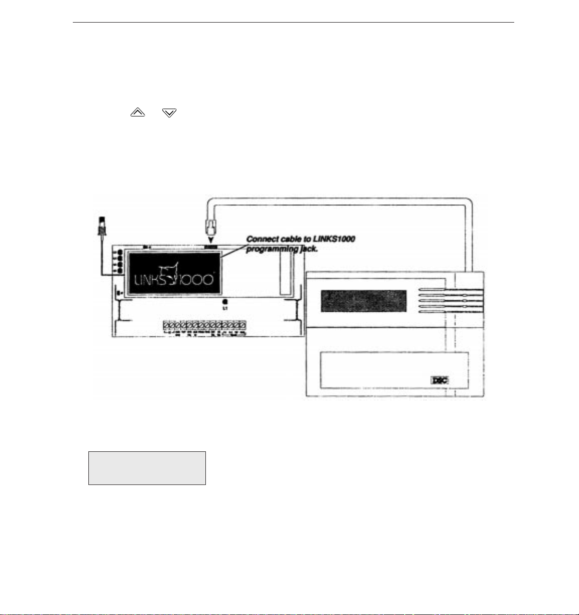
Connect the modular connector of the Programmer to the modular jack on the LINKS1000. Press any key to
activate the Programmer. The LCD screen will light up.
Note:
The LINKS1000 Programmer is menu driven (see Table 1 for a list of menu messages):
• use ‘up’ and ‘down’ arrows to scroll through the various menu fields
• when the desired field is displayed, use the [
• or use the numbers shown in parentheses to go directly to the desired menu or item
• use the [#] key to enter data and exit the section.
Before a cellular service provider will give the Cellular Phone parameters, you must first give the LINKS1000
Electronic Serial Number (ESN). The ESN is found on the LINKS itself (in hexadecimal), or can be read via the
Programmer (in hexadecimal).
If the ESN was not found on the LINKS1000, scroll to the “Read LINKS” menu. Select the ESN and the LCD
will display the ESN in hexadecimal form.
Record the ESN here:
The following parameters must be obtained from the Cellular carrier:
If the screen does not light up, check to see if 4 AA batteries were correctly installed in the back of
the Programmer.
✱✱
✱] key to select it
✱✱
l_____ l_____l - l_ ____l_____l _____l_____l_____l _____l
Cellular
• The cellular telephone number for the LINKS
• The System I.D. l____ _l_ ____l _____l _____ l_ ____l
• The Initial Paging Channel l____ _ l_ ____ l _____ l
l_____ l_ ____l _____ l -l_____l ____ _l_ ____ l -l_ ____l_ ____l_ ____l_ ____l
7

Programming the LINKS1000
Step 1.
Step 2.
Step 3.
NOTE:
Step 4.
Step 5.
NOTE
Programming the Cellular Telephone Number
Scroll to “Write LINKS” and press [
Enter the area code and phone number for the LINKS. Press [#] to store and exit.
Program the Cellular Network Parameters
While still in “Write LINKS” menu, scroll to “System I.D.” and press [
System I.D. number. Press [#] to store and exit.
Scroll to the “Initial Page” and press [
and keys. Press [#] to store and exit.
the
Scroll to “Access Class” and press [
Press [#] to store and exit.
Enabling Downloading
While still in the “Write LINKS” menu, scroll to “Downloading?” and press [
and keys, choose either “Enabled” or “Disabled”. Press [#] to store and exit.
Only LINKS1000 version 2.10 or higher will support this function. This option will display on
non-supported versions, but will not be accessible.
With the Downloading feature “Enabled,” the LINKS1000 will answer ANY call placed to the
LINKS1000 cellular telephone number, therefore generating cellular charges. If Downloading via the
LINKS1000 will not be used, the Downloading feature must be disabled.
AC Failure Reporting Option
The option of sending an AC failure is done via the AC Failure reporting display. Scroll to the ‘AC
Tbl Sent?’ screen and press [
Press [#] to store and exit.
With the option ‘Enabled’ the LINKS1000 WILL report loss of AC power.
With the option ‘Disabled’ the LINKS1000 WILL NOT report loss of AC power.
Only LINKS1000 version 2.20 or higher will support this function. This option will display on
non-supported versions, but will not be accessible.
Emergency Phone Number
The AUX IN terminal provides a Panic type alarm to the LINKS1000. When this terminal is briefly shorted
to ground, the LINKS1000 will dial the phone number that is programmed in the emergency phone
number location.
Only LINKS1000 version 3.0 or higher will support this function. This option will display on
non-supported versions, but will not be accessible.
: This input is a 24-hour, silent terminal and the Panic phone call will be connected through the
cellular network.
Select the LINKS Write menu, then select the Emergency Phone Number item.
Enter the phone number exactly as it would be dialed on a standard cellular phone. Press [#] to
exit the item and store the phone number into the LINKS1000 memory. (See “How the LINKS1000
Works” for instructions on how to connect a phone to the LINKS1000 for use with the emergency
phone number.)
✱✱
✱] to select. Scroll to “LINKS Phone #” and press [
✱✱
✱✱
✱] to select. Enter the five digit
✱✱
✱✱
✱] to select. Choose either “A SIDE 333” or “B SIDE 334” using
✱✱
✱✱
✱] to select. (This is automatically set by the Programmer.)
✱✱
✱✱
✱] to select. Using the
✱✱
✱✱
✱]. Press the
✱✱
and keys to toggle either ‘Enable’ or ‘Disable’.
✱✱
✱] to select.
✱✱
Disconnecting the LINKS1000 Programmer
Step 1.
Step 2.
Step 3.
NOTE
operate when the Programmer is plugged in.
8
Scroll to “Main Menu”.
Press [#], wait for the display to go blank.
Disconnect the modular cord from the LINKS1000. Done
: Unplug the Programmer from the LINKS1000 when finished programming. The LINKS1000 will not
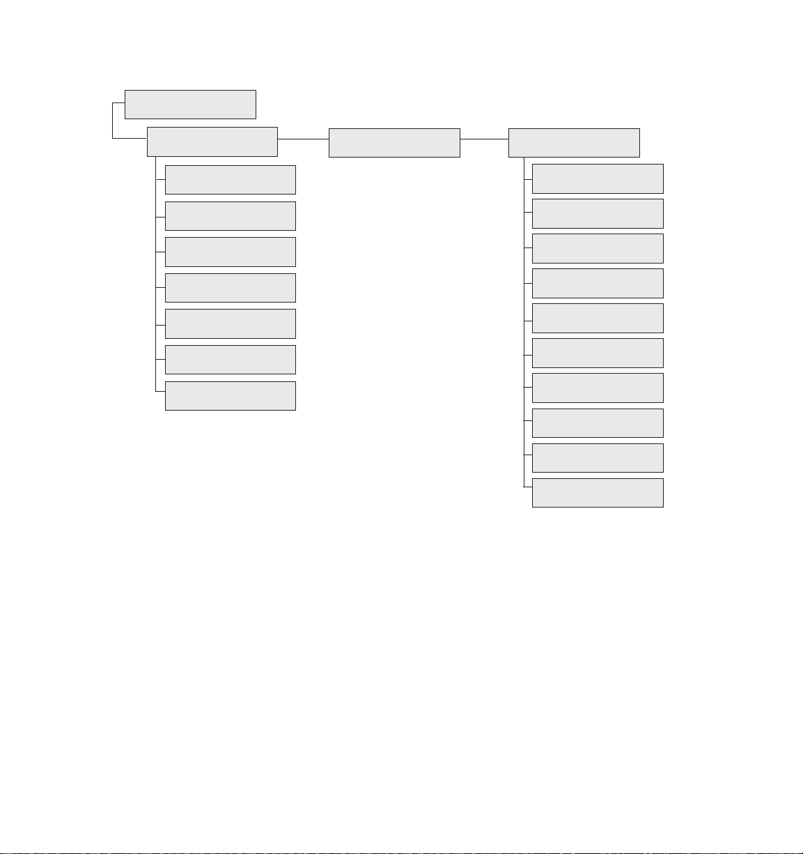
Table 1 — List of LINKS1000 Programmer Menu Messages
Main Menu
(0) Write LINKS (1) Trouble (2) Read LINKS
(0) LINKS Phone # (0) LINKS Phone #
(1) System I.D. (1) ESN
(2) Initial Page (2) System I.D.
(3) Access Class (3) Initial Page
(4) Downloading (4) Access Class
(5) AC TBL Sent (5) Group ID Mark
(6) Emergency Phone # (6) Prefrd Sys Mark
See Table 3 on page 28
for Trouble Messages
and explanations
(7) Downloading
(8) AC TBL Sent
(9) Emergency Phone #
9
INSTALLATION
Mounting the Cabinet
It is important to mount the LINKS1000 as close to the DSC / Sur-gard alarm control panel as possible
3 feet is the recommended maximum distance between the two devices. If the devices are mounted in an
under-over arrangement, always mount the LINKS1000 on top. It is recommended that all wiring between the
control panel and the LINKS1000 be in a tamper and attack-resistant conduit.
Keep in mind the LINKS1000 antenna must be mounted above ground level. If necessary, Antenna
Extension Kits are available from your distributor. Remember cellular likes height. The antenna should be
installed in a physically secured location to avoid tampering.
As much as reasonably possible the LINKS1000 should not be located near sources of interference. These sources
include EMI generated by televisions or heavy electric motors such as those found in heating or air conditioning units.
Remove printed circuit board and wall mounting hardware from cardboard retainer inside cabinet. Before attaching
the cabinet to the wall, press the white nylon mounting studs through the holes in the back of the cabinet.
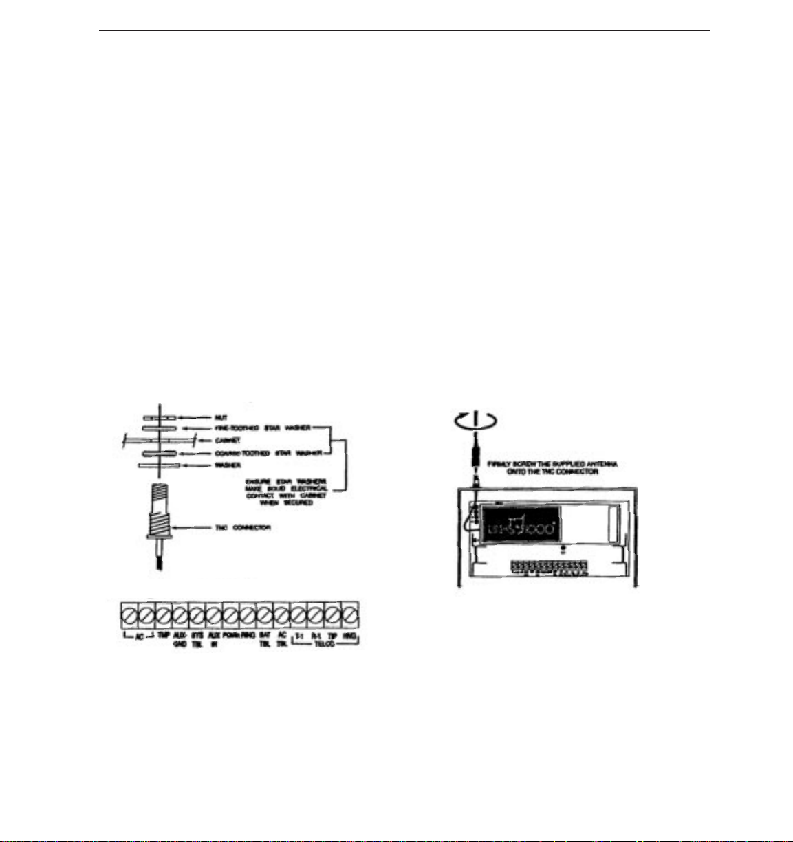
Mounting the Antenna
NOTE:
An antenna should always be connected to the LINKS1000 whenever it is operated. The unit will not
function properly if an antenna is not installed.
Before attaching the antenna, first secure the TNC connector and cable attached to the LINKS unit in the hole
in the top of the cabinet using the hardware provided. Ensure the star washers make solid electrical contact
with the metal cabinet; refer to the illustrations below.
The antenna should be mounted as high above ground level as possible while at the same time taking care not
to place the antenna under a Radio Frequency shield of any kind. I.E. do not mount the antenna directly beneath
a metal roofing over hang. Cellular works best when in an unobstructed “line of sight” to the cellular antenna site.
.
Wiring Connections
Do not connect the transformer or battery until all other wiring, including the antenna connection, has been completed
and checked. Incorrect wiring connections may cause the LINKS1000 unit to operate improperly.
“AC” Power Terminals
For proper operation, the LINKS1000 requires its own transformer.
to power the LINKS1000.
16.5 VAC transformer with a minimum 40 VA rating to supply AC power to the LINKS1000. Do not connect the
transformer to an outlet that is controlled by a switch.
FTC3716 transformer.
Note: All terminals are power limited except for the battery leads. All power limited wiring shall be
installed using FPL, FPLR, FPLP or permitted substitute cable.”
10
Do not connect the transformer or battery until all other wiring is complete. Use a
UL Listed systems should employ the ATC-Frost PIN
Do not use the control panel transformer
 Loading...