

Page 1
Inst allation Instructions
LC-105DGB
Shock & Glass Breakage Detector
LC-105DGB belongs to the new generation of glass breakage detectors. The LC-105DGB can detect glass cutting by diamond in addition
t o t he impr oved detection of g las s br eak ag e. This is ach ie ved by our new all- digita l si gnal p r o ces sing.
The LC -105DGB offers the solution for the false-alarms problem. The LC-105DGB detects the unique patterns of sound emitted by breaking or
cutting glass. The LC -105DGB does not have to be attached to the window, providing volume protection, and allows the protection of several
windows using one detector.
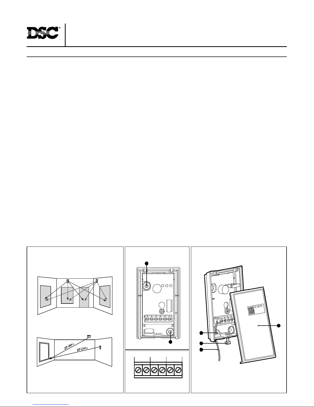
Fig. 1 - Detector Mounnting
Fig. 4 - Terminal block
1 2 3 4 5 6
TAMPER
- 12V +
RELAY
A
A
Fig. 2 - Detector Installation
TYPICAL INSTALLATION
Mounting
The detector offers flexible installation. It can be either ceiling mounted or wall mounted as shown in Fig. 1.
Selecting mounting location
If heavy blinds or curtains cover the glass, you must locate the detector behind the blinds on the window frame or above it, otherwise the blinds
might block the sound. Make sure to test the unit thoroughly using a glass break simulator for proper detection. Install the detector in a direct
line of sight with the protected glass. Do not mount the unit in front of air ducts, or close to bells (measuring 0.5m or larger in diameter). For
pr otecting s everal windows in one room, locate the detec tor at opti mal distance from them to achi eve the bes t detec tion.
Note: for symmetrical cover of the detection area it is recommended to place the detector on the ceiling.
CONN ECTING THE DETECTOR (Fig. 2,3&4)
1. Use a small screwdriver to release the top of the case and lift open the case (Fig. 3-1,2) There is no need to remove the PC B (Printed Circuit
Board) from the case).
2. Insert the wires through the w iring hole (Fig. 3-3).
3. Use the mounting holes (Fig. 2-A) to mount the detector.
4. Connect the wires to the terminal. (Fig.4).
5. Close the case.
JUMPERS
LED ON: LEDS enabled
LED OFF: LEDS disabled
Shock ON: This is the normal working mode. Both breaking glass sound and breaking glass shock-wave
are necessary for generating an alarm.
Shock OFF: This mode is used only for installation settings. The sound of breaking glass is enough to generate an alarm.
WIRE CONNECTIONS
Terminal Block Connections (See fig. 4).
Terminal 1 (Marked "-"). Connect to the return Voltage or ground of the control panel.
Term inal 2 (Marked "+"). Connec t to the posi tive Voltage of 9-16 VDC sour ce (us ually from the alarm control unit).
Terminals 3 & 4 (Marked TAMPER ). If a Tamper function is required connect these terminals to a 24 hours normally closed protective zone in
the c ontrol unit. If the fr ont cover of the detector is opened, an immedi ate alarm signal wi ll be sent to the c ontrol unit.
Term inals 5 & 6 ( Marked RELAY). These ar e the output relay c ontacts of the detector. Stand by - N.C / A larm -N.O
Fig. 3 - Detector Installation
4
2
1
3
Page 2
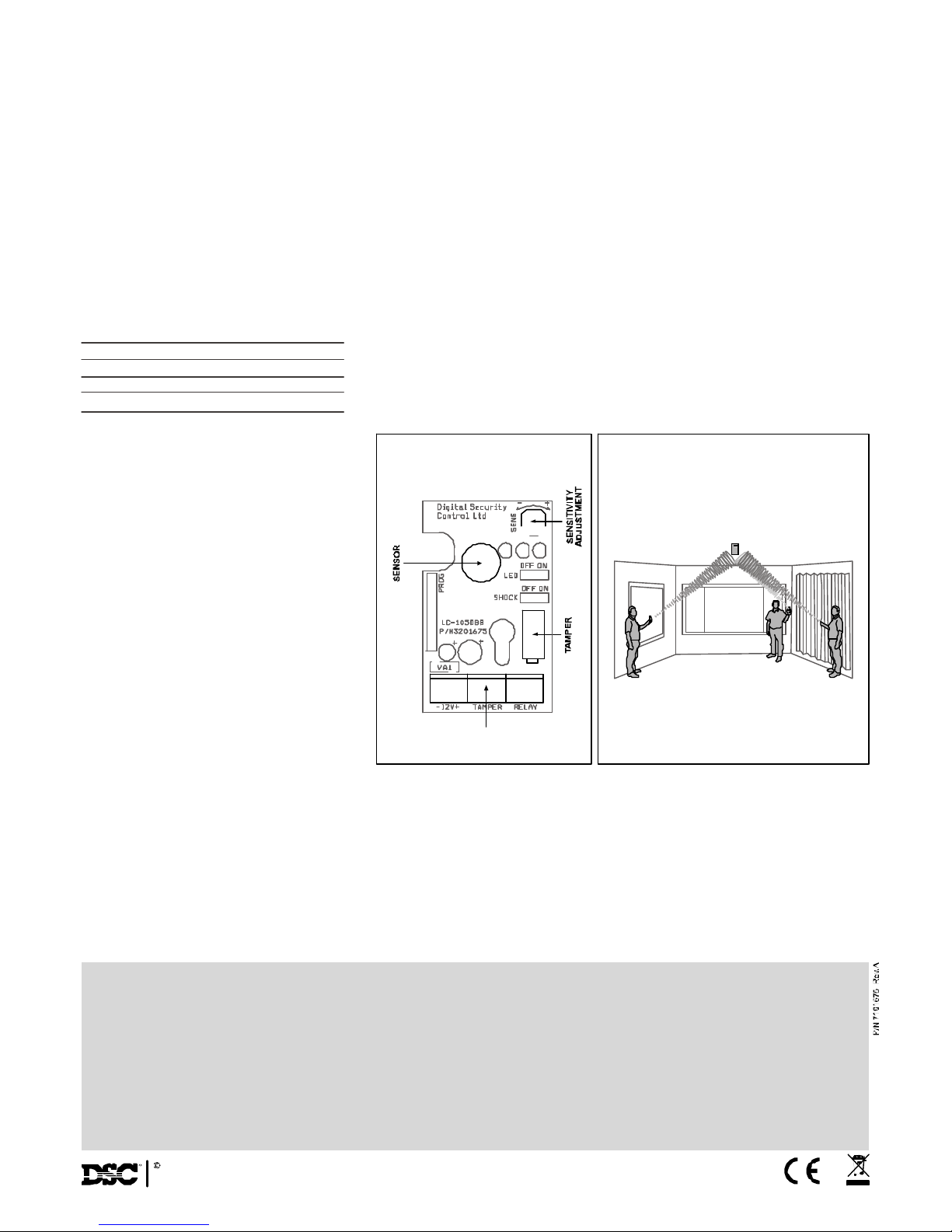
Fig. 6 - Detector testFig. 5 - PCB Layout
BLOCK CONNECTOR
LIMITED WARRAN TY: Digital Security Controls Ltd, warr ants that for a period of 12 m onths from the date of pur chase, the product shall be free of defe cts in materials and workmanship under nor mal use and that in
fulfillment of any breach of such warranty. Digital Security Controls Ltd shall, at its option, repair or re place the defective equipment upon ret urns of the e quipment to its repair d epot. This war ranty applies only to defects
in parts and workmanship and no t to damage incurred in shipping or ha ndling, or damag e due to causes beyond the contr ol of Digital Security Controls Ltd, such as lightning, excessive voltage mechanical shock, water
damage, or damage arising out of abuse, alteration or impr oper a pplication of the equipment.
The forego ing warr anty shall apply only to the or iginal buyer, and is and shall be in lieu of any and all other w arr anties, whether expressed or implied and of all other obligations or liabilities on the part of Digital Security
Controls Ltd . Digital Security Controls Ltd neither assumes responsibility for, nor au thorizes any other per son purpo rting to act on its behalf to modify or t o change this warr anty, nor to assume for it any other w arr anty or
liability concerning this product.
In no event shall Digita l Security Controls Ltd be liable for any direct, indirect or consequential damages, loss of anticipated pr ofits, loss of time or an y other losses incurred by the buyer in connection with the purchase,
in stallation or oper ation or failure of t his product.
Motion detecto rs can only detect mo tion within the de signated are as as Shown in th eir re spective installation instructions. They cannot discriminate betwe en intrud ers and intended occupants. Mot ion detectors do not
provide vo lumetric area prote ction. They have multiple beams of detection and motion can only be detected in unobstructed area s covered by these beams. They cannot detect motion which occurs behind walls, ceilings,
flo or, closed doors, glass partitions, glass doors or windows. Any
type of tamperin g whe ther intentional or unintentional such as m asking , painting, or spra ying of any ma terial on the lenses, mirr ors, windows or any o ther part of th e detection system w ill impair its proper oper ation.
Passive infrared motion detectors oper ate by sensing changes in temperatur e. Howe ver their effectiveness can be reduced when the ambient temper atur e rises near or above body temper ature or if ther e are intentional
or u nin ten tion al so ur ces of heat in or n ea r the detection area. Some of these heat sources could be h ea ter s, radia tor s, stoves, barb equ es, firep laces, su nligh t, steam vents, light ing and so on.
WARNING: Digital Security Controls Ltd, recommends that the entire sys tem be com plet ely t ested o n a reg ula r basis. How ever, d espit e f requ ent test ing , an d d ue to , bu t n ot lim ited to , crim inal t am perin g
or electrical disruption, it is possible for this product to fail to perform as expecte d.
Important informa tio n : Ch an g es or mod if ica ti on s not ex pre ssl y ap p ro ved b y D ig it al Secu ri ty Co n tro ls L td c ou ld v oi d t h e u se r's a ut h or it y t o operate this equipment.
2005 Digital Security Controls Ltd
Toronto, Canada
www.dsc.com
TE STING THE DETECTOR
Set the jumpers as follows: LED =ON, SHOCK=ON.
1. Use the simulator in manual mode to simulate the noise of glass breaking . Check that the yellow LED is ON. If it does not light, a sensitivity
calibration is necessary. Rotate the "SEN S" potentiometer clockwise to increase the sensitivity, and counterclockwise to decrease it. 2. Use your
hand or a padded object to firmly strike on door or table. If the green LED does not light, adjust the sensitivity as necessary. 3. Use the Simulator
in automatic mode and check that the red LED lights. If the red LED, yellow LED and green LEDS are ON, your detector is w orking properly.
* Cutting of glass by a diamond causes only the red LED to light. If the red LED does not light try adjusting the sensitivity until the red LED lights.
FINAL TESTING
* Set the jumpers as follows: LED =ON, SHOCK=OFF.
* To ensure maximum protection against false alarms, activate any device in the area, w hich might automatically activate, like cycle pumps,
generator s, heating/air conditioni ng units , etc. If thes devices trigger an alarm, mount the unit i n a different location.
* Set the jumpers to their normal working position: SHOCK = ON.
WIRE SIZ E REQUIREMENTS
U se #22 AWG (0.5mm) or wires with a larger diameter. Use the following table to determine required wire gauge (diameter) and length of the
wire between the detector and the control panel.
TE CHNICAL SPECIFICATION
Power Input 9-16VDC
Current Standby: 15mA at 12 Vdc
Consumption Active: 40mA at 12Vdc
Detection Range 10m (33ft), Max.
Cutting 3m
Mounting Ceiling or Wall
Alarm Output Relay N.C. 50mA/24Vdc
10 Ohm in line resistor
Tamper Switch N.C. 50mA/24Vdc with
10Ohm in line resistor
Operating -20oC to 50oC
Temperature R ange (-4oF to 122oF)
Operating Humidity 95% max relative humidity
Range non condensing
Storage -30oC to 70oC
Temperature R ange (-22oF to 158oF)
RFI Protection 30V/m 10 -1000 MHz
EMI Protection 50,000V electrical
interference from lightning
Dimensions 79mm x 48mm x 21mm
Weight 40gr. ( 1.41oz.)
Wire Length m 200 300 400 800
Wire Diameter mm .5 .75 1.0 1.5
Wire Length ft 800 1200 2000 3400
Wire Gauge # 22 20 18 16
 Loading...