

Page 1
Inst allation Instructions
LC-102PIGBSS
Professional Passive Infrared Shock & Glass Breakage
Detectors with Pet Immunity
A new generation of professional movement spread spectrum analyzing PIR, Shock & Glass Breakage detectors.
The detector provides an analysis of envi ronmental conditions through the entire movement spread frequency spectrum.
It listens for sounds of breakin g glass, which produces two sequential signals of different frequencie “SHOCK” and “GLASS”. The
unique phased frequency detection circuitry of this detector allows detection of both shock signal and the strong signal of glass
breakage crea ting a false alarm free detector. The detector does not need to be attached to the window, providing volume protection,
and allowing you to protect several windows with one detector.
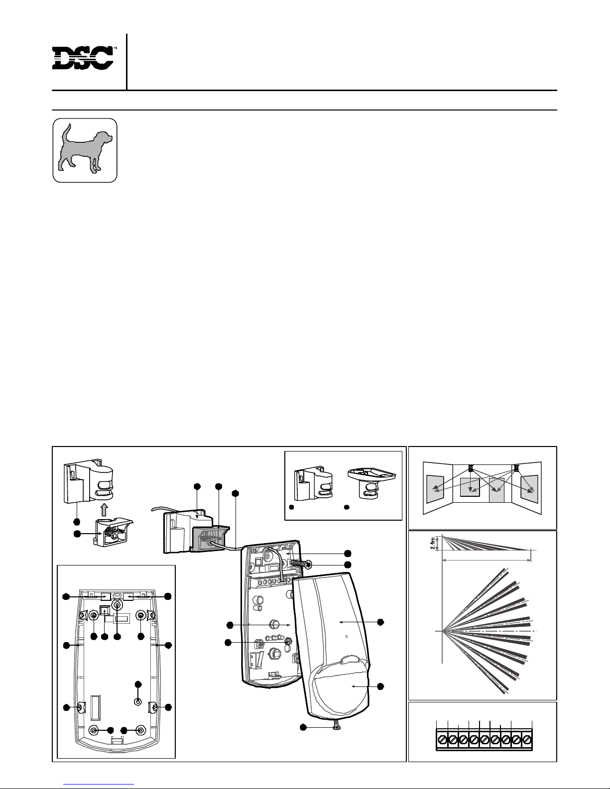
FIG 2 - Knockout holes
FIG 1 - Bracket Installation
FIG 6 - Lens pattern
Wall Mount
Bracket
Ceiling Mount
Bracket
FIG 3 - Bracket options
1 2
CC
A
B B
B B
AA
DD
C
CC
TYPICAL INSTALLATION
Select mounting loc ation
Choose a location in front of the protected windows, in direct line of sight within 4.5m. In case of more then one windo, place the detector in the center
area facing the windows, make sure that this location will be most likely to intercept an intruder, that may across the PIR beams. See PIR detection beams.
See SHOCK and GLASS detection area Fig.5,Fig.6. If heavy blinds or curtains cover the glass, you m ust locate the detector behind the blinds on the
window frame or a bove it, otherwise the blinds might block the sound.
Avoid the following loca tions: *Facing direct sunlight. *Facing areas subject with temperature changes. *Areas with air ducts or substantial air flows.
*Facing metal doors. *Close to door entrance bells mea suring 2” (or larger) in diameter.
MOUNTING DETECTOR BASE
1. To remove th e front cover, unscrew the holding screw and gently raise the front cover Fig.4-11. 2. To remove the PC board, carefully unscrew the holding
screw located on the PC board Fig.4-9. 3. Brea k out the desired holes for proper installing Fig.2 B or C. 4. The circular and rectangular indentations at
the bottom base are th e knockout holes for wire entry. You may also use mounting holes that are not in use for running the wiring into the detector.(For
option with bracket - lead wire through the bracket, Fig4-7) 5. Mount the detector base to the wall, corner or ceiling. ( For option with bracket install bracket)
Fig.1, Fig.3 6. Reinstall the PC board by fully tightening the holding screw. Connect wire to terminal block. 7. Replace the cover by inserting it back in
the appropriate closing pins and screw in the holding screw.
DETECTOR INSTALLATION
Terminal Block Connections (See Fig.7)
Terminals 1 & 2 - Marked “T1, T2” (TAMPER) If a Tamper function is required conn ect these terminals to a 24-hour normally closed protective zone in
the control unit. If the fr ont cover of the detector is opened, an immediate al arm signal will be sent to the control uni t.
Terminals 3 & 4 - Marked “PIR: NC, C” These are the output PIR relay contacts of the detector. Connect to a normally closed zone in the control panel.
Terminal 5 - Marked “EOL” - End of line option.
Terminals 6 & 7 - Marked “MIC: NC, C” These are the output MICROPHONE relay contacts of the detector. Connect to a normally closed zone in the
con trol panel.
Terminal 8 - Marked “-” (GND) Connect to the negative Voltage output or ground of the control panel.
Termin al 9 - Marked “+” (+12V) Connect to a positive Voltage output of 8.2 -16Vdc source (usually from the alarm control unit)
FIG 4 - Detector Installation
FIG 7 - T erminal block
FIG 5 - Detector Mounnting
15m
11
6
5
8
4
10
9
1 3
7
1 2 3 4 5 6 7 8 9
T2 EOL - 12V +
MIC
NCT1 C NC C
PIR
1
3
Page 2
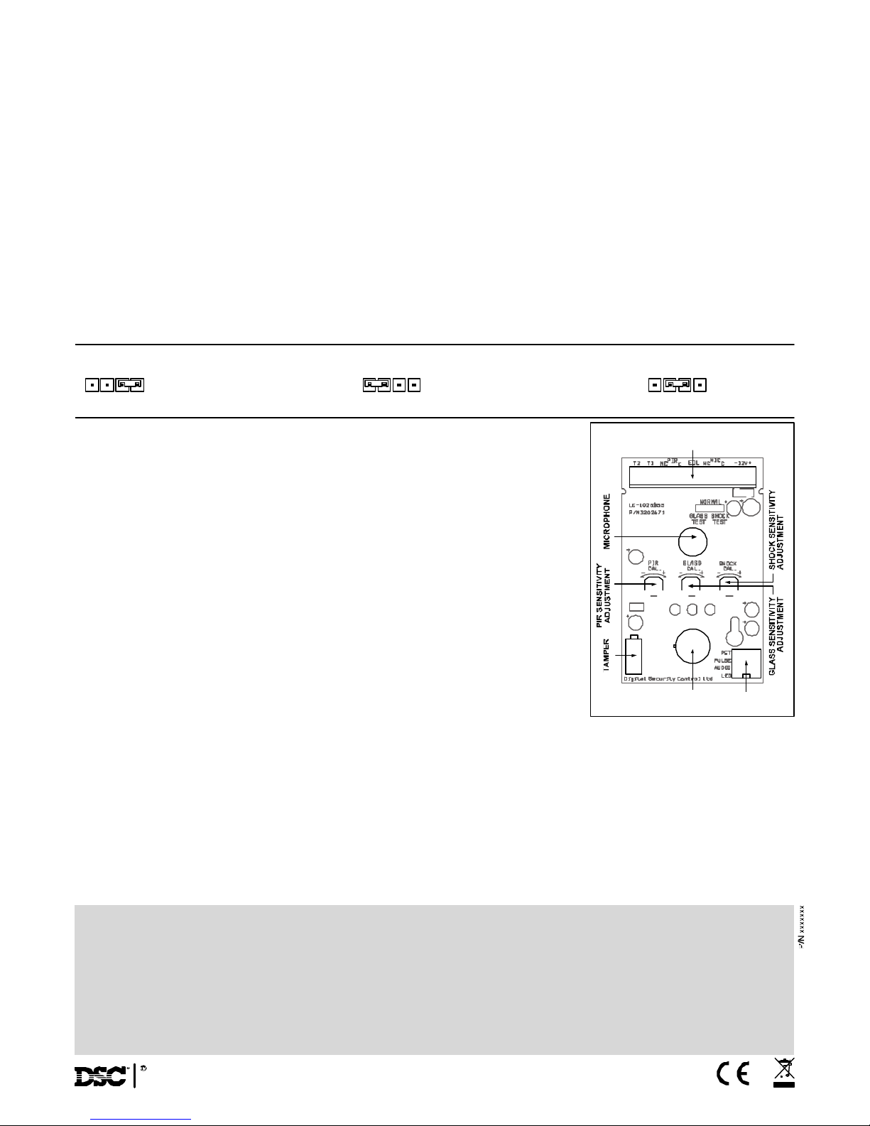
Shock / Glass Adjustment Use only during testing and setting
SHOCK - for adjustment of the
fre quency sensitivity with
potentiometer “SHOCK”
SETTING - UP THE DETECTOR
PIR SENSITIVITY ADJUSTMENT: Switch 3 of DIP-4. Use for Setting ”PULSE” - provides sensitivity control of PIR according to the environment.
Position Left - ”On”- High sensitivity For stable environments. Position Right - ”OFF”- Low sensitivity For harsh environments.
“PIR CAL” POTENTIOMETER ADJUSTMENT: According to protected area range. Use the potentiometer marked “PIR CAL” to adjust the detection
sensitivity be tween 15% and 100% according to walk test in the protected area. (Factory setting is 57%). Rotate the potentiometer clockwise to increase
range, counter-clockwise to decrease ran ge. Always walk test and re-adjust if required.
LED IN DICATION OF ALARM SIGNAL: Switch 1 of DIP-4. Use for Setting “LED” - provides control of Alarm signal LED indication.
Position Left - “On” - LED enable. Position Right “OFF” - LED disable.
SOUND SENSITIVITY ADJUSTMENT: Switch 2 of DIP-4. Use for Setting “AUDIO” - provides control of sound detection sensitivity. Position Left -
“On” - reducing the sensitivity of sound detection by 50%. (Use in small room). Position Right “OFF” - Sensitivity of sound detection 100%.
PET IMMUNITY SETTING: Switch 4 of DIP-4. U se for Setting “PET” 15kg - 25kg. Position Left “ON” Immunity to PET up to 15 kg.
Position Right “OFF” I mmunity to PET up to 25 kg
TEST PROCEDURES
Wait for one minute warm up time after applying 12-Vdc power. Conduct testing with the protected area cleared of all people. Make sure to test the unit
thoroug hly for proper detection.
Walk test: 1. Remo ve front cover. Set “PULSE” to “ON” position, and set “LED” to “ON” position. 2. Replace the front cover. 3. Start walking slowly
across the detection area. 4. Observe that the red led lights whenever m otion is detected. 5. Allow 5 sec. between each test for the detector to stabilize.
6. After the walk test is completed, yo u can set the “LED” to “OFF” position.
N OTE: Walk tests shoul d be conducted, at least onc e a year, to confirm proper operation and coverage of the detector.
ADJUSTMENT
GLASS - for adjustment of
the high frequency sensitivity
with potentiometer “GLASS”
NORMAL for regular
operation
Gla ss Break adjustment
To adjust the glass break sensitivity, place the jumpe r accordingly GLASS TEST marking. Green (SHOCK)
LED is constantly ON. Now you can adjust the sensitivity by rotating the GLASS CAL potentiometer. Operate
the Sound Break Simulator* near the protected window and rotate the potentiometer GLASS CAL clockwise to increase sensitivity, and counter-clock-wise to decrease sensitivity until the Yellow and Red LEDs
are illuminating for each glass break sound.
Note: When the jumper is set for GLASS adjustment, only the high frequency sound of breaking glass is
detected. *It is r ecommended to use GLASS-BREAK Simulator FG-701 (CROW p/n 004001)
Shock Adjustment
To adjust the shock setting (increase/decrease sensitivity) place the jumper accordingly SHOCK TEST
marking - Yellow (GLASS) LED is constantly ON. Now you can adjust the sensitivity by rotating the potentiometer
SHOCK CAL. Hit gently on the protected glass and rotate the potentiometer clock-wise to increase sensitivity,
and counter-clock-wise to decrease sensitivity until the Green and Red LEDs are illuminating for each hit.
Note: When the jumper is set for SHOCK adjustment, only the low frequency of the shock signal prior to
glass breakage is detected.
SHOCK/GLASS TEST PROCEDURE
Final Testing
* Make sure to set jum per “GLASS/SHOCK” in position NORMAL. When the jumper is in this position, the
detector will dete ct both shock and sound frequencies. * To ensure maximum protection against false alarms,
activate any device in the are a, which might automatically cycle pumps, gene
Warm Up Period 60 sec
RFI Protection 30V/m 10 - 1000MHz
EMI Protection 50,000V of electrical interference from lighting
Visible Light
Protection st able against halogen light 2.4m (8ft)or reflected light
Detection range Glass up to 10m (900); PIR up to 15m (WA lens)
LEDs indicator Yellow LED (GLASS) - glass break signal for testing & adjustment
Green LED (SHOCK) - shock signal for testing & adjustment
Red LED (ALARM) - alarm signal:
Fleshing light - glass & break detection or glass & shock & PIR
detection
Constant light - PIR detection
Dimensions 118mm x 62.5mm x 41mm (4.65” x2.46” x1.61”)
Weight 110 gr.
TECHNICAL SPECIFICATION
Detection Method Quad (Four element) PIR & electret microphone
Detection Speed 0.15 - 3.6 m/sec
Power Input 8.2 - 16 Vdc
Current Draw Alarm PIR :16.5mA; Alarm Shock & Glass
22mA; Alarm all: 18mA
Standby: 16.5 mA
BI Directional
Temp.
Compensation YES
Pulse Count 1, AUTO
Alarm Period 2 sec
Alarm Output N.C 28Vdc 0.1 A with 10 Ohm series protection
resistors
Tamper Switch N.C 28Vdc 0.1A with 10 Ohm series protection
resistor - open when cover is remove
NO RMAL
GLASS
TEST
SHOCK
TEST
GLASS
TEST
SHOCK
TEST
NORMAL NORMAL
GLASS
TEST
SHOCK
TEST
BLOCK CONNECTOR
PYROSENSOR
SWITCH FOR
SETTINGS
FIG 8 - PCB LAYOUT
LIMITED WARRANTY: Digital Security Controls Ltd, warrants that for a period of 12 months from the date of purchase, the product shall be free of defects in materials and workmanship under normal use and that in fulfillment of any
breach of such warranty. Digital Security Controls Ltd shall, at its option, repair or replace the defective equipment upon returns of the equipment to its repair depot. This warranty applies only to defects in parts and workmanship and not to
damage incurred in shipping or handling, or damage due to causes beyond the control of Digital Security Controls Ltd, such as lightning, excessive voltage mechanical shock, water damage, or damage arising out of abuse, alteration or
improper application of the equipment.
The foregoing warranty shall apply only to the original buyer, and is and shall be in lieu of any and all other warranties, whether expressed or implied and of all other obligations or liabilities on the part of Digital Security Controls Ltd. Digital
Security Controls Ltd neither assumes responsibility for, nor authorizes any other person purporting to act on its behalf to modify or to change this warranty, nor to assume for it any other warranty or liability concerning this product.
In no event shall Digital Security Controls Ltd be liable for any direct, indirect or consequential damages, loss of anticipated profits, loss of time or any other losses incurred by the buyer in connection with the purchase, installation or operation
or failure of this product.
Motion detectors can only detect motion within the designated areas as Shown in their respective installation instructions. They cannot discriminate between intruders and intended occupants. Motion detectors do not provide volumetric area
protection. They have multiple beams of detection and motion can only be detected in unobstructed areas covered by these beams. They cannot detect motion which occurs behind walls, ceilings, floor, closed doors, glass partitions, glass
doors or windows. Any
type of tampering whether intentional or unintentional such as masking , painting, or spraying of any material on the lenses, mirrors, windows or any other part of the detection system will impair its proper operation.
Passive infrared motion detectors operate by sensing changes in temperature. However their effectiveness can be reduced when the ambient temperature rises near or above body temperature or if there are intentional or unintentional sources
of heat in or near the detection area. Some of these heat sources could be heaters, radiators, stoves, barbeques, fireplaces, sunlight, steam vents, lighting and so on.
WARNING: Digital Security Controls Ltd, recommends that the entire system be completely tested on a regular basis. However, despite frequent testing, and due to, but not limited to, criminal tampering or electrical disruption,
it is possible for this product to fail to perform as expected.
Important information: Changes or modi fi cat ion s n ot exp ressl y ap pro ved by D igi ta l Secu rit y Co nt rol s Lt d cou ld voi d t h e use r's au th ori ty to op erat e t hi s eq uip men t .
2005 Digital Security Controls Ltd
Toronto, Canada
www.dsc.com
 Loading...