

Page 1
IT-410
IT-410
Xanboo
Gateway
(c)
ALEXOR
DG0009498
≤ 100 ‘ (30.5m)
4.9’ (1.5m)
(a)
(b)
≥
2’ (0.61m)
USB
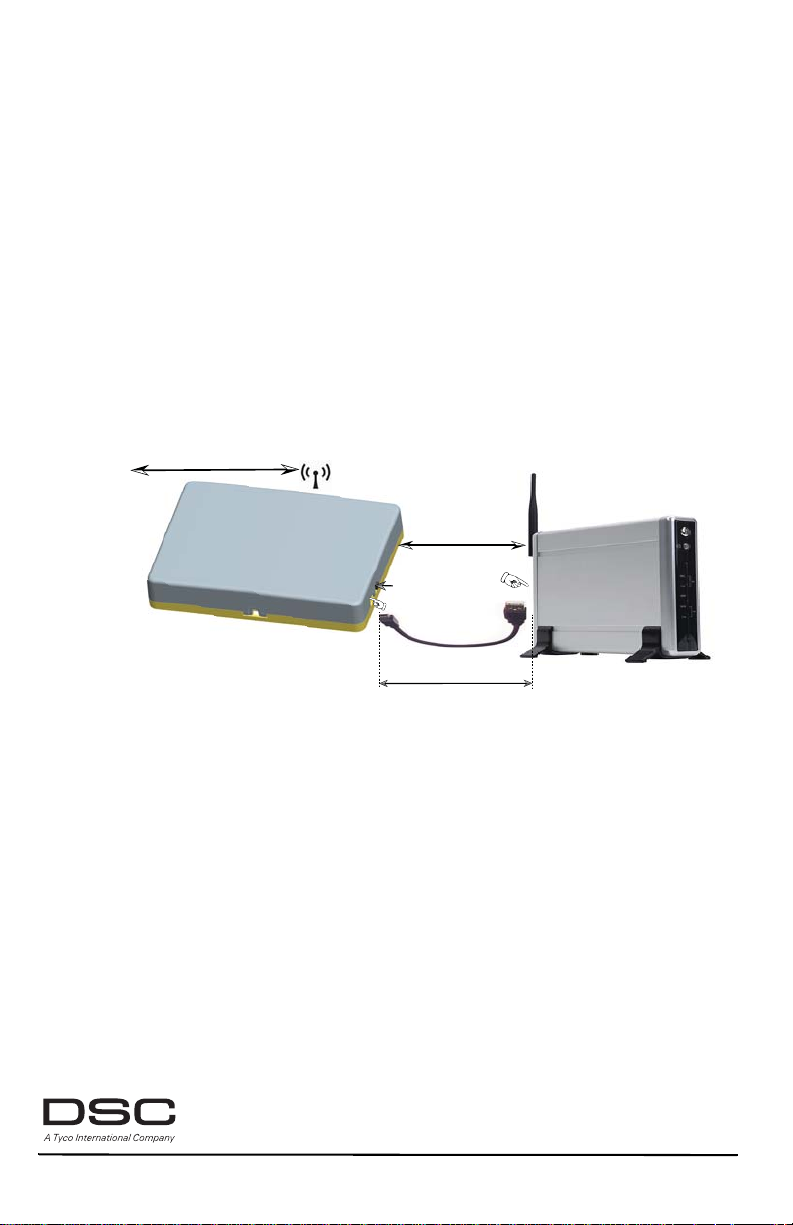
Figure 1: IT-410 Interconnection
Figura 1: IT-410 Interconexión
Figure 1: IT-410 Interconnexion
Two Way Wireless Communicator USB Interface
USB Interfaz de Comunicación Inalámbrica Bidireccional
USB Interface de communicateur bilatéral sans fil
The IT-410 provides an interface to communicate with th e ALEXOR via two-way RF interface. The IT-410 is connected to the
Xanboo Gateway via a USB connection. Environmental specifications are provided in Table 1 at the end of this document.
Note: The Xanboo Gateway is a 3rd Party device. It must be installed and operating before starting installation of the IT -410.
El IT-410 proporciona un interfaz para comunicar con el ALEXOR vía interfaz de dos vías del RF. El IT-410 está conectado con la
entrada de Xanboo vía un conectador del USB. Las Especificaciones Ambientales son sumini stradas en la Tabla 1 al final de
este documento.
Nota: El Xanboo Gateway es un dispositivo de terceros. El debe ser instalado y estar operativo antes de iniciar la instalación del IT-410.
IT-410 fournit une interface pour communiquer avec l’AL EXOR p ar l’intermédiai re de l’interface bi-directionnell e de rf. L’IT-410
est relié au passage de Xanboo par l’intermédiaire d’un connecteur d’USB.. Les caractéristiques environnementales se trouvent
au Tableau 1 à la fin de ce document.
Remarque : La passerelle Xanboo est un dispositif tiers. Elle doit être installée et doit fonctionner avant de commencer
l’installation de l’IT-410.
Installation Sheet
Hoja de instalación
Notice d’installation
v1.0
Page 2

IT-410 PRE INSTALLATION CAUTIONS
CAUTION: The IT-410 shall be installed by Service Persons only. Service Person is defined as a person havin g the appropriate
technical training and experience necessary to be aware of hazards to which that person may be exposed in performing a task
and can also take measures to minimize the risks to that person or other persons.
CAUTION: The external wiring must be routed in a manner that prevents:
• Excessive strain on wire and terminal connections and to ensure that it does not generate any hazard for the end-user;
• Loosening of terminal connections; and
• Damage of conductor insulation.
CAUTION:The first keypad enrolled with the ALEXOR is the primary keypad. Ensure that a primary keypad is enrolled on the
ALEXOR before installing the IT-410.
IT-410 INSTALLATION
Perform the following steps to install the IT-410: (See
1. Temporarily mount the IT-410 in a suitable indoor location, within 100 ft. (30.5 m) of the ALEXOR panel.
2. Using the supplied 4.9’ (1.5m) USB cable, insert the mini-B plug into the IT-410 side connector. See
3. Insert the USB 2.0 plug into the USB slot on the Xanboo Gateway. See
Note: Wait five (5 ) secon ds be fore procee ding to the next step. (The IT-410 performs self test when power is applied via USB ).
4. Perform the followi ng step s to e nroll the IT-410 from the first (
a. At the primary keypad, press
b. On the right side of the IT-410, press and release the
c. At the primary keypad, ensure that the Electronic Serial Number (ESN) is displayed. Press * to confirm ESN.
d. At the primary keypad, press * to accept next available slot or enter 02 - 04 for the keypad number assigned to IT-410.
e. At the primary keypad observe the display
5. At the IT-410, press the
a. If a STRONG signal is received, the bell will sound once and
b. If a WEAK signal is received, the bell will sound three (3) times and
c. If there is no response from the ALEXOR, reposition the IT-410 and repeat step 5 until
Note: When Location is Good, the Placeme nt Test should be re-run three (3) times to ensure a good placement.
d. At the primary keypad, press the # key three (3) times to exit Installer programming.
e. Desk mount, or use (2) two screws provided to mount IT-410 in its final location as determine d by the Placemen t Test. Ensure that the IT-410
and Xanboo are at least 2’ (0.61m a part ).
6. The IT-410 is now installed and is ready for configuration using procedures found in the Xanboo documentation.
*8 [installer code][898]
Enrollment
button and observe result on the keypad LCD:
Figure 1
on the front cover of this docu ment).
primary
. Observe that
Enrollment
Activate Device for Tes
Location is Good
Figure 1 (b)
.
) ALEXOR wireless keypad:
Wireless Enrollment Mode
button. See
Figure 1 (c)
t,
Exit #
, proceed to Step 5 for placement test instructions.
will be displayed on the LCD.
Location is Bad
will be displayed on the LCD.
Figure 1 (a)
is displayed on the keypad LCD.
.
Location is Good
.
is displayed on the LCD.
IT-410 CUIDADOS ANTES DE LA INSTALACION
CUIDADO: El IT-410 debe ser instalado solamente por Personal Técnico calificado. Personal Técnico es la persona que posee el entrenamiento y experiencia técnica apropiada necesaria para conocer los riesgos a los cuales pueda estar eventualmente expuesta al realizar
una tarea, y también pueda tomar medidas para reducir los riesgos a ella misma o a otras personas.
CUIDADO:Los cables externos deben ser encaminados de forma en evitar:
• T ensión excesiva en el cable y terminal de conexión y garantizar que no se genere ningún riesgo al usuario final;
• Desprendimiento de los terminales de conexión; y
• Daños al aislamiento del conductor.
CUIDADO: El primer teclado registrado en el ALEXOR es el teclado primario. Certifíquese que un teclado primario esté registrado en el
ALEXOR antes de instalar el IT-410.
INSTALACION DEL IT-410
Siga la secuencia a continuación para instalar el IT-410: (Ver la Figura 1 en la tapa de este documento).
1. Monte el IT-410 provisoriamente en un lugar interno adecuado, a como máximo 100 pies (30,5 m) del panel ALEXOR.
2. Utilizando el cable USB de 4,9 pies (1,5m) suministrado, inserte el conector mini-B en el conector lateral del IT -4 10. V er la
3. Inserte el conector USB 2.0 del Xanboo Gateway. Ver la
Nota: Espere cinco ( 5) segund os a ntes de seguir con el paso siguiente. (El IT-410 realiza una autoprueba cuando se c onect a la energía a
través del USB).
4. Realice los siguientes pasos para registrar el IT-410 del primer teclado inalámbrico (primario) ALEXOR:
a. En el teclado primario, presione
bido en el teclado LCD.
b. En el lateral derecho del IT-410, presione y suelte el botón de
c. En el teclado primario, certifíquese que el Número Serial Electrónico (ESN) es exhibido. Presione * para confirmar el ESN.
d. En el teclado primario, presione * para aceptar la próxima ranura disponible o digite 02 - 04 para el número del teclado atribuido al IT-410.
e. En el teclado primario observe la indicación de
5 para instrucciones de prueba de posicionamiento.
5. En el IT-410, presione la llave de Registro y observe el resultado en el teclado del LCD:
a. Si se recibe una señal
b. Si se recibe una señal
c. Si no hubiera re spuesta del ALEXOR , repo si cion e el IT-410 y repita el paso 5 hasta que sea exhib ido
cuada).
Nota: Cuando la Localizació n es Adecuad a, la Prueba de Posicio namiento debe rea lizarse tres (3) veces p ara garan tizar una
buena localización.
d. En el teclado primario, presione la tecla # tres (3) veces para salir de la programación del Instalador.
e. Montaje en superficie o utilice los dos (2) tornillos proveídos para montar el IT -410 en la p ared en su localizació n definitiva (según determinado
en la Prueba de Posicionamiento). Certifíquese que el IT-410 y el Xanboo Gateway están por lo menos 2 pies (0.61m) aparte.
6. El IT-410 ah ora e stá inst al ado y listo p ara co nfigur ación u tilizando lo s pr ocedimiento s enc ontrad os en la docu ment ación del Xanboo.
*8 [código del instalador][898]
FUERTE
, la campanilla sonará una vez y
DEBIL
, la campanilla sonará tres (3) veces y
Figura 1 (b)
.
. Verifique que el Modo
Registro
. Ver la
Activate Device for Test, Exit #
Location is Good
Location is Bad
Wireless Enrollment
Figura la 1 (c)
(Activar Dispositivo para Prueba, Salida #), prosiga en el Paso
.
(Localización Adecuada) se exhibirá el LCD.
(Localización Inadecuada) se exhibirá en el LCD.
Location is Good
Figura 1 (a)
.
(Registro inalámbrico) sea exhi-
(Localización Ade-
PRÉCAUTIONS DE PRÉ-INSTALLATION DE L’IT-410
MISE EN GARDE: L'IT-410 doit être installé p ar u n techn icien qualifié seule ment . Un tec hnicie n qua lifié est d éfini c omme ét a nt un e personne ayant la formation technique et l'expérience appropriées nécessaires pour connaître les dangers auxquels elle s'expose en effectuant ces tâches et des mesures à prendre pour minimiser les risques pour elle-même et pour les autres.
MISE EN GARDE:Le câblage externe doit être fait de manière à prévenir:
• Une tension trop grande sur le fil et sur les bornes de connexion, et tout danger pour l'utilisa teur final;
• Le desserrage des bornes de connexion; et
1
Page 3

• La détérioration de l'enveloppe isolante.
MISE EN GARDE: Le premier clavier enregistré avec ALEXOR est le clavier principal. Vérifiez qu'un clavier principal est enregistré avec
ALEXOR avant l'installation de l'IT-410.
INSTALLATION DE L’IT-410
Effectuez les étapes suivantes pour installer l'IT-410: (voir Figure 1 sur la couverture de ce document).
1. Installez l'IT-410 temporairement à l'intérieur, à 30,5 m (100 pi) maximum du panneau ALEXOR.
2. À l'aide du câble USB de 1,5 m (4,9 pi) fourni, insérez la fiche mini-B dans le connecteur latéral de l'IT-410. Voir
3. Insérez le connecteur USB 2.0 dans la fente USB sur la passerelle Xanboo. Voir
Remarque : Attendez (5) secondes avant de passer à la section suivante. (L'IT-410 effectue un test automatique lorsqu'il est mis sous ten-
4. Effectuez les étapes suivantes pour enregistrer l'IT-410 sur le premier (principal) clavier ALEXOR sans fil :
5. Sur l'IT-410, appuyez sur le commutateur d'enregistrement et observez le résultat sur le clavier LCD :
6. L'IT-410 est à présent installé et prêt à être configuré à l'aide des procédures se trouvant dan s la documentation Xanboo.
sion par l'intermédiaire de l'USB).
a. Sur le clavier principal, saisissez
b. Sur le côté droit de l'IT-400, appuyez sur le bouton
c. Sur le clavier principal, vérifiez que le Numéro de série électronique (ESN) est affiché. Saisissez * pour confirmer l'ESN.
d. Sur le clavier principal, saisissez * pour accepter la fente disponible suivante ou saisissez 02-04 pour le numéro de clavier assigné au IT-410.
e. Vérifiez qu'"
portée.
a. Si un signal
b. Si un signal
c. Si ALEXOR ne répond pas, repositionnez l'IT-410 et refaites l'étape 5 jusqu'à ce qu'"
Remarque : Lorsque l'Emplacem ent est Bon, le te st de port ée doit ê tre effect ué trois ( 3) fois po ur assu rer un bon placeme nt.
d. d. Sur le clavier principal, appuyez trois (3) fois sur la touche # du clavier pour sortir du Mode paramétrage Installateur.
e. Fixation sur bureau ou utilisez les deux (2) vis fournie pour fixer l’IT-410 à son emplacement définitif (déterminé par le test de portée). Vérifiez
Activez le dispositif pour tester, Sortie #
FORT
est reçu, la sonnerie retentit une fois et "
FAIBLE
que l’IT-410 et la passerelle Xanboo sont au moins 2 pieds (0.61m) à part.
*8 [Code Installateur][898].
Vérifiez que "
Enregistrement
" est affiché sur le clavier principal, passez à l'étape 5 pour les instructions sur le test de
est reçu, la sonnerie retentit trois (3) fois et "
Emplacement bon
Emplacement mauvais
Figure 1 (b)
Mode Attribution sans fil
puis relâchez. Voir
" est affiché à l'écran.
.
Figure 1 (c)
" est affiché à l'écran.
Emplacement bon
Figure 1 (a)
" est affiché sur le clavier LCD.
.
.
" est affiché.
Digital Security Controls (D SC) warrants the original purchaser tha t for a
period of twelve (12) months from the date of purchase, the product shall be
free of defects in materials and workmanship u nder no rmal use . Dur i ng the
warranty period, Digital Security Controls shall, at its option, repair or replace
any defective product upon return of the product t o its factor y, at no charge
for labour and materials. Any r eplacement and/or repaired parts are warranted for the remainder of the ori gi nal warr an ty or ni nety ( 90) days, whi chever is longer. The original purchaser must promptl y notify Digi tal Security
Controls in writing that there is defect in material or workmanship, such written notice to be received in all events prior to expiration of the warranty
period. There is absolutely n o warranty on s oftware and all software products are sold as a user license under the terms of the so ftware license
agreement included with the product . The Custo mer assumes a ll re sponsibility for the proper selection, installation, operation and maintenance of any
products purchased from DSC. Custom products ar e onl y warr anted to the
extent that they do not functi on upon delivery. In such cases, DSC can
replace or credit at its option.
International Warranty
The warranty for internatio nal customers is the same as for any customer
within Canada and the United States, with the exception that Digital Security
Controls shall not be responsible for any cus toms fees, taxes, or VAT that
may be due.
Warranty Procedure
To obtain service under this warranty, please return the item(s) in question to
the point of purchase. All author ized distributors and deale rs have a warranty program. Anyone returning goods to Digital Security Controls must first
obtain an authorization nu m b e r. Digital Security Controls will not acce pt a n y
shipment whatsoever for which prior authorization has not been obtained.
Conditions to Void W arran ty
This warranty applies only to defe cts in parts and workmanship rel ating to
normal use. It does not cover:
•damage incurred in shipping or handling;
•damage caused by disaster such as fire, flood, wind, earthquake or lightning;
•damage due to causes beyond the control of Digital Security Controls such
as excessive voltage, mechanical shock or water damage;
•damage caused by unauthorized attachment, alterat ions, modi ficat ions, or
foreign objects;
•damage caused by peripherals (unless such peripheral s were suppl ied by
Digital Security Controls);
•defects caused by failure to provid e a suitable installati on enviro nment for
the products;
•damage caused by use of the products for purposes other than those for
which it was designed;
•damage from improper maintenance; or
•damage arising out of any other abuse, mishandling or improper application
of the products.
Items Not Covered by Warranty
In addition to the items which void the Warranty, the following items shall not
be covered by Warranty:
(i) freight cost to the repair centre ;
LIMITED WARRANTY
(ii) products which are not identif ied with DSC' s prod uct la bel and l ot num-
ber or serial number; or
products disassembled or repaired in suc h a manne r as t o adver sel y a ffect
performance or prevent adequate inspection or testing to verify any warranty
claim.
Access cards or tags returned for replacement under war rant y wil l be credited or replaced at DSC's o ption. Products not covere d by this warranty, or
otherwise out of warranty due to age, misuse, or damage shall be evaluated,
and a repair estimate shall be provided. No repair work will be performed
until a valid purchase order is received f rom the Customer and a Return
Merchandise Authorisation number (RMA) is issued by DSC's Customer
Service.
Digital Security Controls’ liability for failure to repair the product under this
warranty after a reasonable number of att empts will be l i mit ed to a re pl acement of the product, as the exclusive remedy for breach of warranty. Under
no circumstances shall Digital Security Controls be liable for any special,
incidental, or consequential damages based upon breach of warranty,
breach of contract, negligence, strict liability, or any other legal theory. Such
damages include, but are not limited to, loss of profits, loss of the product or
any associated equipment, cost of capital, cost of substitute or replacement
equipment, facilities or services, down time, purchaser’s time, the claims of
third parties, including customers, and injur y to proper ty. The laws of some
jurisdictions limit or do not allow the disclaimer of consequential damages. If
the laws of such a jurisdiction apply to any claim by or against DSC, the limitations and disclaimers contained here shall be to the greatest extent permitted by law. Some states do not allow the exclusion or limitat ion of incidental
or consequential damages, so that the above may not apply to you.
Disclaimer of Warranties
This warranty contains the entire warranty and shall be in lieu of any and all
other warranties, whether expressed or implied (including all implied warranties of merchantability o r fitness for a pa rticular pu rpose) a nd of all o ther obl igations or liabilities on the part of Digital Security Controls Digital Security
Controls neither assumes responsibility for nor authorizes any other person
purporting to act on its behal f to modify or to chang e this warranty, nor to
assume for it any other wa rranty o r liability c onc erning this prod uct.
This disclaimer of warranties and limited warranty are governed by the laws
of the province of Ontario, Canada.
WARN IN G: D
SYSTEM BE COMPLETELY TESTED ON A REGULAR BASIS
FREQUENT
OR ELECTRICAL DISRUPTION, IT IS POSSIBLE FOR THIS PRODUCT TO FAIL TO
PERFORM
Out of Warranty Repairs
Digital Security Controls wil l at its option repair or replace out -of-warranty
products which are returned to i ts factory acco rding to the following condi tions. Anyone returning goo ds to Digital Security Cont rols must fi rst obtain
an authorization number. Digital Security Control s will not accept any shipment whatsoever for which prior authorization has not been obtained.
Products which Digital Security Con t ro ls det erm ines t o be r epair abl e wil l be
repaired and returned. A set fee whi ch Digital Secur it y Contr ols h as pr edetermined and which may be revised from time to time, will be charged for
each unit repaired.
IGITAL SECURITY CONTROLS RECOMMENDS THAT THE ENTIRE
TESTING, AND DUE TO, BUT NOT LIMITED TO, CRIMINAL TAMPERING
AS
EXPECTED
.
. H
OWEVER, DESPITE
2
Page 4

Digital Security Controls garantiza al comprador o riginal que p or un periodo
de doce meses desde la fecha de compra, el producto está libre de defectos en materiales y hechura en uso normal. Dura nte el periodo de la garan tía, Digital Security Controls, decide sí o no, reparará o reemplazará
cualquier producto defectuoso devolviendo el producto a su fábrica, sin
costo por labor y materiales. Cualquier repuesto o pieza reparada está
garantizada por: el resto de la garantía original o noventa (90) días, cualquiera de las dos opciones de mayor tiempo. El propietario original debe
notificar puntualmente a Digital Security Controls por escrito que hay un
defecto en material o hechura, tal aviso escrito debe ser recibido en todo
evento antes de la expiración del periodo de la garantía. No hay absolutamente ningún tipo de garantía sobre softwa re y todos los p roductos de so ftware son vendidos como una licencia de usuario bajo los términos del
contrato de licencia del software incluido con el producto. El comprador
asume toda responsabilidad por la apropiada s elección , inst alación , ope ración y mantenimiento de cualquier producto comprado a DSC. La g arantía
de los productos hechos a medida alcanzan solam e nte a aq uellos productos que no funcionen al momento de la entrega. En tales casos, DSC
puede reemplazarlos o acreditarlos, a opción de DSC.
Garantía Internacional
La garantía para los clientes internacionales es la misma que para cualquier cliente de Canadá y los Estados Un idos, co n la excepció n q ue Digit al
Security Controls no será responsable por cualquier costo aduanero,
impuestos o VAT que puedan ser aplicados.
Procedimiento de la Garantía
Para obtener el servicio con esta garantía, po r favor devuelva el(los) artículo(s) en cuestión, al punto de compra. Todos los distribuidores autorizados
tienen un programa de garantía. Cualquiera que devuelva los artículos a
Digital Security Controls, debe primero obtener un nú mero d e autoriza ción.
Digital Security Controls, no aceptará ningún cargamento de devolución sin
que haya obtenido primero el número de autorización.
Condiciones para Cancelar la Garantía
Esta garantía se aplica solamente a defectos en partes y en hechura concerniente al uso normal. Esta no cubre:
• daños incurrido s en el mane jo de envío o carga mento
• daños causados por desastres tales como incendio, inundación, vientos,
terremotos o rayos eléctricos.
• daños debido a causas más allá del control de Digital Security Controls,
tales como excesivo voltaje, choque me cánico o dañ o por agua.
• daños causados por acoplamientos no autorizados, alteraciones, modificaciones u objetos extraños.
• daños causados por periféricos (al menos que los periféricos fueron
suministrados por Digital Security Controls);
• defectos causa dos por falla en al suministro un ambiente apropiado para
la instalación de los productos;
• daños causad os por el uso de productos, p ara propósitos diferentes, p ara
los cuales fueron designados;
• daño por mantenim iento no apropia do;
• daño ocasion ado por otros abusos, ma l manejo o u na aplicación no apropiada de los productos.
Items no cubiertos por la Garantía
Además de los ítems que cancelan la Garantía, los siguientes ítems no
serán cubiertos por la Garantía: (i) costo de flete hasta el centro de reparación; (ii) los productos que no sean identificados con la etiqueta de producto de DSC y su número de lote o número de serie; (iii) los productos
que hayan sido desen samblados o reparados de ma nera tal que a fecten
adversamente el funcionamiento o no permitan la adecuada inspección o
pruebas para verificar cualquier reclamo de garantía. Las tarjetas o etique-
GARANTIE LIMITÉE
La société Digital Security Controls garantit le produit contre toutes défectuosités matérielles et d’assemblage dans des conditions normales d’utilisation, à l’acheteur original, pendant une période de douz e mo is à p artir de
la date d’achat. Dans l’application de cette garantie, la société Digital Security Controls s’e nga ge, à son cho ix, à r éparer ou à rem pla cer t out mat éri el
défectueux dès son retour à un dépôt de réparation, sans frais de main
d’oeuvre et matériels. Tout remplacement et/ou réparation sont garantis
pendant le reste de la durée de la garantie originale ou quatre ving t dix (90)
jours, ou l’une ou l’autre est la plus longue. Le propriéta ire original doit avertir la société Digital Security Controls par courrier que le matériel ou
l’assemblage sont défectueux ; dans tous les cas, cette notification d oit être
reçue avant l’expiration de la période de garantie.
Garantie Internationale
La garantie pour les clients internationaux est la même que pour tous les
clients au Canada et aux Etats-Unis, sauf que la société Digital Security
Controls ne sera pas responsable des frais de douanes, taxes, ou TVA qui
pourraient être dus.
Procédure pour la Garantie
Pour obtenir un service sous garantie, veuillez retourner les produit(s) en
question au point d’achat. Tous les distributeurs autorisés et vendeurs ont
un programme de garantie. Quiconque retourne des marchandises à la
société Digital Security Controls doit tout d’abord obtenir un numéro d’autorisation. La société Digital Security Controls n’acceptera aucun envoi pour
lequel une autorisation préalable n’aura pas été obtenue.
Conditions d’annulation de la Garantie
Cette garantie ne s’applique qu’aux vices de matériels et d’assembla ge liés
à une utilisation normale. Elle ne couvre pas:
• dommage encouru lors de l’expédition ou la manutention;
• dommage causé par un désastre tel qu’un incendie, inondation, vent,
tremblement de terre ou foudre ;
• dommage dû à des causes hors du contrôle de la société Digital Security
Controls tel que voltage excessif, choc mécanique ou dommage des eaux
;
• dommage causé par attachement non autorisé, changements, modifications ou objets étrangers ;
• dommage causé par périphériques (à moins que les périphériques ne
soient fournis par la société Digital Security Controls) ;
GARANTÍA LIMITADA
tas de acceso devueltas para su reemplazo bajo la garantía, serán acreditadas o reemplazadas a opción de DSC. Los productos no cubiertos por la
presente garantía, o de otra manera fuera de la garantía debido al transcurso del tiempo, mal uso o daño, serán evaluados y s e proveerá una estimación para la reparaci ón. No se real izará ningún t rabajo de repara ción
hasta que una orden de compra válida enviada por el Cliente sea recibida y
un número de Autorización de Mercadería Devuelt a (RMA) sea emitido por
el Servicio al Cliente de DSC.
La responsabilidad de Digital Security Controls, en la falla para reparar el
producto bajo esta garantía después de un número razonable de intentos
será limitada a un reemplazo del producto, como el rem edio exclu sivo p ara
el rompimiento de la garantía. Bajo ninguna circunstancias Digital Security
Controls, debe ser responsable por cualquier daño especial, incidental o
consiguiente basado en el rompimiento de la garantía, rompimiento de
contrato, negligencia, responsabilidad estricta o cualquier otra teoría legal.
Tales daños deben incluir, pero no ser limitados a, perdida de ganancias,
perdida de productos o cualquier equipo asociado, costo de capital, costo
de substitutos o reemplazo de equipo, facilidades o servicios, tiempo de
inactividad, tiempo del comprador, los reclamos de terceras partes, incluyendo clientes, y perjuicio a la propiedad. Las leyes de algunas jurisdicciones limitan o no permiten la renuncia de daños consecuentes. Si las leyes
de dicha jurisdicción son aplicables sobre cualquier reclamo por o en contra de DSC, las limitaciones y renuncias aquí contenidas serán las de
mayor alcance permitidas por la ley. Algunos estados no permiten la exclusión o limitación de daños incidentale s o consecuentes, e n tal caso lo arriba
mencionado puede no ser aplic able a Ud.
Renuncia de Garantías
Esta garantía contiene la garantía total y de be p revalecer sobre cualquiera
otra garantía y todas las otras garantías, ya sea expresada o implicada
(incluyendo todas las garantías implicadas en la merc ancía o fijada p ara un
propósito en particular) Y todas las otras obligaciones o responsabilidades
por parte de Digital Security Controls. Digital Security Controls, no asume o
autoriza a cualquier otra persona para que actué en su representación,
para modificar o cambiar esta gara ntía, ni para asu mir cualquier o tra garantía o responsabilidad concerniente a este producto.
Esta renuncia de garantía y garantía limitada son regidas por el gobierno y
las leyes de la provincia de Ontario, Canadá.
ADVERTENCIA:
sea completamente probado en forma regula r . Sin embargo, a p esar de las
pruebas frecuentes, y debido a, pero no limitado a, s abotaje criminal o interrupción eléctrica, es posible que este producto falle en trabajar como es
esperado.
Reparaciones Fuera de la Garantía
Digital Security Controls, en su opción reemplazará o reparará los productos por fuera de la garantía que sean devueltos a su fábrica de acuerdo a
las siguientes condiciones. Cualquiera que esté regresando los productos
a Digital Security Controls, debe primero obtener un número de autorización. Digital Security Controls, no aceptará ningún cargamento sin un
número de autorización primero.
Los productos que Digital Security Controls, determine que son reparables
serán reparados y regresados. Un cargo fijo que Digital Security Controls,
ha predeterminado y el cual será revisado de tiempo en tiempo, se exige
por cada unidad reparada.
Los productos que Digital Security Controls, determine que no son repara-
bles serán reemplazados por el producto más equivalente disponible en
ese momento. El preci o actual en el mercado del prod ucto de re emplazo
se cobrará por cada unidad que se reemplace.
• défauts causés par l’impossibilité de fournir un environnement d’installation adapté aux produits ;
• dommage causé par l’utilisation des produit s po ur des us ages au tres que
ceux pour lesquels ils ont été conçus
• dommage pour mauvais entretien ;
• dommage provenant de tout autre mauvais traitement, mauvaise manutention ou mauvaise utilisation des produits.
S’il y a un problème de réparation du produit après un nombre raisonnable
de tentatives au titre de la présente garantie, les obligations contractuelles
de la société Digi tal S ecu rit y Co ntr ols ser on t li mit ées au r emp lace ment du
produit, comme seule réparation de l’inobservation de la garantie. En
aucun cas la Société Digital Security Controls ne sera responsable des
dommages particuliers, accidentels ou indirects basés sur l’inobservation
de la garantie, une rupture de contrat, une négligence, une responsabilité
stricte ou sur toute autre théorie juridique. De tels dommages incluent, mais
ne sont limités à, une perte de profit, une perte de produit ou tout autre
équipement associé, au coût de capital, au coût de remplacement de l’équipement, à l’aménagement ou services, à l’indisponibilité, au temps de
rachat, aux réclamations des tiers, notamment les clients, aux dommages
et intérêts à la propriété, etc .Stipulation d’exon ération de garanties
Cette garantie contient l’entière garantie et remplace toutes les autres
garanties, qu’elles soient explicites ou implicites (notamment toutes les
garanties implicites de marchandise ou aptitude pour un usage particulier)
et de toutes autres obligations ou responsabilités de Digital Security
Controls. Digital Security Controls n’assume et n’autorise aucun e autre personne prétendant agir en son nom de modifier ou changer cette garantie,
n’assume pour cela aucune autre garantie o u responsabilité c oncernant ce
produit.
Cette stipulation d’exonération de garanties et garantie restreinte s ont gouvernées par les lois de la province de l’Ontario, Canada.
ATTENTION:
tème soit testé régulièrement. Toutefois, même si vous faites des essais
périodiques, il peut arriver que le fonctionnement du produit ne soit pas
conforme aux spécifications en raison notamment, mais pas exclusivement, d’interventions criminelles ou de panne de courant.
Digital Security Controls, recomienda que todo el sistema
Digital Security Controls recommande que la totalité du sys-
3
Page 5

Réparations en dehors de la Garantie
Digital Security Controls réparera à son choix ou remplacera en dehors
de la garantie les produits renvoyés à son usine dans les conditions suivantes. Quiconque retourne des produits à Digital Security Controls doit
d’abord obtenir un numéro d’autorisation. Digital Security Controls
n’acceptera aucun envoi quel qu’il soit, pour lequel une autorisation préalable n’aura pas été obtenue.
IMPORTANT - READ CAREFULL Y: DSC Software purchased with or without Products and Components is Copyrighted and
This End-User License Agreement (EULA) is a lega l agreem ent betw een
You
(the company, individual or entity who acquired the SOFT W ARE an d
any related HARDWARE) and
sion of Tyco Safety Products Canada Ltd., the manufacturer of the integrated security systems and the developer of the software and any
related products or components (‘HARDWARE’) which you acquired.
If the DSC software product (‘SOFTWARE PRODUCT’ or ‘SOFTWARE’)
is intended to be accompanied by HARDWARE, and is NOT accompanied by new HARDWARE, You may not use, copy or install the SOFTWARE PRODUCT. The SOFTWARE PRODUCT includes computer
software, and may include associated media, printed materials, and
‘online’ or electronic documentation.
Any software provided al ong with the SOFTWARE PRODUCT that is
associated with a separate EULA is licensed to You under the terms of
that license agreement.
By installing, copying, downloading, storing, accessing, or otherwise
using the SOFTWARE PRODUCT, You agree unconditionally to be
bound by the terms of this EULA, even if this EULA is deemed to be a
modification of any previous arrangement or contract. If You do not agree
to the terms of this EULA, DSC is unwilling to license the SOFTWARE
PRODUCT to You, and You have no right to use it.
C.
SOFTWARE PRODUCT LICENSE
The SOFTWARE PRODUCT is protected by copyright laws and
international copyright treaties, as well as other intellectual property
laws and treaties. The SOF TWARE PRODUCT is licensed , not sold,
under the following terms:.
1. GRANT OF LICENSE This EULA g rants You the following rights:
(a)
Software Installation and Use
may have only one copy of the SOFTWARE PRODUCT installed.
(b)
Storage/Network Us e
installed, accessed, displayed, run, shared or used concurrently on or
from different computers, including a workstation, terminal or other
digital electronic device (‘Device’). In other words, if You have several
workstations, You will have to acquire a license for each workstation
where the SOFTWARE will be used.
(c)
Backup Copy
PRODUCT, but You may only have one copy per licen se installed at
any given time. You may use the back-up copy solely for archival
purposes. Except as expressly provided in this EULA, You may not
otherwise make copies of the SOFTWARE PRODUCT, includin g the
printed materials accompanying the SOFTWARE.
2.
DESCRIPTION OF OTHER RIGHTS AND LIMITATIONS
(a)
Limitations on Reverse Engineering, Decompilation and
Disassembly
disassemble the SOFTWARE PRODUCT, except and only to the
extent that such activity is expressly permitted by applicable law
notwithstanding this limitation. You may not make any changes or
modifications to the Software, without the written permission of an
officer of DSC. You may not remove any proprietary notices, marks or
labels from the Software Product. You shall institute reasonable
measures to ensure compliance with the terms and conditions of this
EULA.
(b)
Separation of Components
licensed as a single product. Its component parts may not be
separated for use on more than one HARDW ARE un it.
(c)
Single INTEGRATED PRODUCT
with HARDWARE, then the SOFTWARE PRODUCT is licensed with
the HARDWARE as a single integrated product. In this case, the
SOFTWARE PRODUCT may only be used with the HARDWARE as
set forth in this EULA.
(d)
Rental
PRODUCT. You may not make it av ailable to others or post it o n a
server or web site.
(e)
Software Product Transfer
under this EULA only as part of a permanent sale or transfer of the
HARDWARE, provided You retain no copies, You transfer all of the
SOFTWARE PRODUCT (including all component parts, the media
and printed materials, any upgrades and this EULA), and provided
the recipient agrees to the terms of this EULA. If the SOFTWARE
PRODUCT is an upgrade, any transfer must also include all prior
versions of the SOFTWARE PRODUCT.
(f)
Termination
terminate this EULA if You fail to comply with the terms and
- You may make back-up copies of the SOFTWARE
- You may not reverse engineer, decompile, or
- You may not rent, lease or lend the SOFTWARE
- Without prejudice to any other rights, DSC may
Digital Security Controls (DSC),
- The SOFTWARE PRODUCT may not be
- You may transfer all of Your rights
is purchased under the following license terms:
- For each license You acquire, You
- The SOFTWARE PRODUCT is
- If You acquired this SOFTWARE
Les produits que Digital Security Controls juge être réparables seront
réparés et renvoyés. Les frais prédéterminés par Digital Security
Controls, et sujets à un rajustement périodique, seront facturés po ur chaque unité réparée.
Les produits que Digi tal Security Control s juge ne pas être répara bles
seront remplacés par le produit équivalent le plus proche disponible à ce
moment. Le prix du marché en cours du produit de remplacement sera
facturé pour chaque unité de remplacement
conditions of this EULA. In such event, You must destroy all cop ies of
a divi-
the SOFTWARE PRODUCT and all of its component parts.
(g)
Trademarks
with any trademarks or service marks of DSC o r its suppliers.
3.
COPYRIGHT
SOFTWARE PRODUCT (including b ut not limited to any imag es,
photographs, and text incorporated into the SOFTWARE
PRODUCT), the accompanyin g pri nted mat eri als, and any copies of
the SOFTWARE PRODUCT, are owned by DSC or its suppliers. You
may not copy the printed materials accompanying the SOFTWARE
PRODUCT. All title and intellectual property rights in and to the
content which may be accessed through use of the SOFTWARE
PRODUCT are the property of the respective content owner and may
be protected by applicable copyright or other intellectual property laws
and treaties. This EULA grants You no rights to use such content. All
rights not expressly granted under this EULA are reserved by DSC
and its suppliers.
4.
EXPORT RESTRICTIONS
reexport the SOFTWARE PRODU CT to any country, pe rson, or entity
subject to Canadian export restrictions.
5.
CHOICE OF LAW
the laws of the Province of Ontario, Canada.
6.
Agreement shall be determined by final and binding arbitration in
accordance with the Arbitration Act, and the parties agree to be
bound by the arbitrator’s decision. The place of arbitration shall be
Toronto, Canada, and the language of the arbitration shall be English.
7. LIMITED WARRANTY
(a)
(b)
(c)
(d)
(e)
WARNING: DSC
COMPLETELY
FREQUENT
NAL TAMPERING OR ELECTRICAL DISRUPTION, IT IS POSSIBLE
FOR
EXPECTED
- This EULA does not grant You any rights in connection
- All title and intellectual property rights in and to the
- You agree that You w ill not export or
- This Software License Agreement is governed by
ARBITRATION
NO WARRANTY
warranty. DSC does not warrant that the SOFTWARE will meet your
requirements or that operation of the SOFTWARE will be
uninterrupted or error free.
CHANGES IN OPERATING ENVIRONMENT -
responsible for problems caused by changes in the operating
characteristics of the hardware, or for problems in the interaction of
the SOFTWARE with non DSC software or ha rdware p roducts.
LIMITATION OF LIABILITY; WARRANTY REFLECTS
ALLOCATION OF RISK
warranties or conditions not stated in this license agreement, entire
liability under any provision of this license agreement shall be limited
to the greater of the amount actually paid by you to license the
SOFTWARE and five Canadian dollars (CAD$5.00). because some
jurisdictions do not allow the exclusion or limitation of liability for
consequential or incidental damages, the above limitation may not
apply to you.
DISCLAIMER OF WARRANTIES
entire warranty and shall be in lieu of any and all other warranties,
whether expressed or implied (including all implied warranties of
merchantability or fitness for a particular purpose) and of all other
obligations or liabilities on the part of DSC. DSC makes no other
warranties. DSC neither assumes nor authorizes any other person
purporting to act on its behalf to modify or to change this warranty,
nor to assume for it any other warranty or liability concerning this
SOFTWARE PRODUCT.
EXCLUSIVE REMEDY AND LIMITATION OF WARRANTY -
Under no circumstances shall DSC be liable for any special,
incidental, consequential or indirect damages based upon breach of
warranty, breach of contract, negligence, strict liability, or any other
legal theory. such damages include, but are not limited to, loss of
profits, loss of the SOFTWARE or any associated equipment, cost of
capital, cost of substitute or replacement equipment, facilities or
services, down time, purchasers time, the claims of third parties,
including customers, and injury to property.
THIS SOFTWARE PRODUCT TO FAIL TO PERFORM AS
- All disputes arising in connection with this
- DSC provides the SOFTWARE ‘as is’ without
-In any event, if any statute implies
- This warranty contains the
RECOMMENDS THAT THE ENTIRE SYSTEM BE
TESTED ON A REGULAR BASIS
TESTING, AND DUE TO, BUT NOT LIMITED TO, CRIMI
.
DSC shall not be
. H
OWEVER, DESPITE
-
4
Page 6

IMPORTANTE – LEA ATENTAMENa TE: el Software DSC comprado con o sin Productos y
• Este Acuerdo de Licencia de Usuario Final (End-UserLicense
Agreement — “EULA”) es un acuerdo legal entre
individuo o entidad que ha adquirido el Software y cualquier Hard ware
relacionado) y
Safety Products Canada Ltd.
de seguridad integrados y programador del software y de todos los
productos o componentes relacionados (“HARD WARE”) qu e usted ha
adquirido.
• Si el producto de s oftware DSC (“PRODUCTO DE SOFTWARE” o
“SOFTWARE”) necesita estar acompañado de HARDWARE y NO
está acompañado de nuevo HARDWARE, usted no puede usar,
copiar o instalar el PRODUCTO DE SOFTWARE. El PRODUCTO DE
SOFTWARE incluye software y puede incluir medios asociados,
materiales impresos y documentación “en línea" o electrónica.
• Cualquier software provisto con el PRODUCTO DE SOFTWARE que
esté asociado a un acuerdo de licencia de usuario final separado es
licenciado a Usted bajo los términos de ese acuerdo de licencia.
• Al instalar, copiar, realizar la descarga, almacenar, acceder o, de otro
modo, usar el PRODUCTO DE SOFTWARE, Usted se somete
incondicionalmente a los límites de los términos de este EULA, incluso
si este EULA es una modificación de cualquier acuerdo o contrato
previo. Si no está de acuerdo con los términos de este EULA, DSC no
podrá licenciar le el PR ODUCTO DE SOFTWARE y Ust ed no t endrá
el derecho de usarlo.
LICENCIA DE PRODUCTO DE SOFTWARE
El PRODUCTO DE SOFTW A RE está protegido por leyes de derecho de
autor y acuerdos de derecho de au tor, así como otros tratados y leyes de
propiedad intelect ual . El PRODUCTO DE SOFT WARE es li c enc i ado, no
vendido.
1. CONCESIÓN DE LICENCIA. Este EULA le concede los siguientes
derechos:
(a)
Instalación y uso del software
adquiere, Usted puede instalar tan sólo una copia del PRODUCTO
DE SOFTWARE.
(b)
Almacenamiento/Uso en red
puede ser instalado, accedido, mostrado, ejecutado, compartido o
usado al mismo tiempo desde diferentes ordenadores, incluyendo u n a
estación de trabajo, terminal u otro dispositivo electrónico
(“Dispositivo”). En otras palabras, si Usted tiene varias estaciones de
trabajo, Usted tendrá que adquirir una licencia para cada estación de
trabajo donde usará el SOFTWARE.
(c)
Copia de seguridad
PRODUCTO DE SOFTWARE, pero sólo puede tener una copia por
licencia instalada en un momento determinado. Usted puede usar la
copia de seguridad solamente para propósitos de archivo. Excepto
del modo en que está expresamente previsto en este EU LA, Usted no
puede hacer copias del PRODUCTO DE SOFTWARE de otro modo,
incluyendo los materiales impresos que acompañan al SOFTWAR E.
2. DESCRIPCIÓN DE OTROS DERECHOS Y LIMITACIONES
(a)
Limitaciones en Ingeniería Reversa, Descompilación y
Desmontado
descompilar o desmontar el PRODUCT O DE S OFTWAR E, excepto y
solamente en la medida en que dicha actividad esté expresamente
permitida por la ley aplicable, no obstante esta limitación. Usted no
puede realizar cambios ni modificaciones al Software, sin el permiso
escrito de un oficial de DSC. Usted no puede eliminar avisos de
propiedad, marcas o etiqueta s del Producto de Software. Usted
debería instituir medidas razonables que aseguren el cumplimiento
de los términos y condiciones de este EULA.
(b)
Separación de los Componentes
SOFTWARE se licencia como un producto único. Sus partes
componentes no pueden ser separadas para el uso en más de una
unidad de HARDWARE.
(c)
Producto ÚNICO INTEGRADO
con HARDWARE, entonces el PRODUCTO DE SOFTWARE está
licenciado con el HARDWARE como un producto único integrado. En
este caso, el PRODUCTO DE SOFTWARE puede ser usado
solamente con el HARDWARE, tal y como se establece más ad elante
en este EULA.
Alquiler
(d)
DE SOFTWARE. No puede disponibilizarlo a terceros ni colgarlo en
un servidor o una página web.
(e)
Transferencia de Producto de Software
todos sus derechos bajo este EULA sólo como parte de una venta
permanente o transferencia del HARDWARE, desde que Usted no
retenga copias y transfiera todo el PRODUCTO DE SOFTWARE
(incluyendo todas las partes componentes, los materiales impresos y
mediáticos y cualquier actualización y este EULA) y desde que el
receptor esté conforme con los términos de este EULA. Si el
PRODUCTO DE SOFTWARE es una actualización, cualquier
transferencia debe incluir también todas las versiones previas del
PRODUCTO DE SOFTWARE.
(f)
Término
terminar este EULA si Usted negligencia el cumplimiento de los
términos y condiciones de este EULA. En tal caso, usted debe
Componentes tiene marca registrada y es adquirido bajo los siguientes términos de licencia:
Usted
(la compañía,
Digital Security Controls, una división de Tyco
– Usted no puede realizar ingeniería reversa,
– Usted no puede alquilar, prestar o arrendar el PRODUCTO
- Sin prejuicio de cualesquiera otros derechos, DSC puede
(“DSC”), el fa bri c an t e d e l o s si st em as
– Para cada licencia que Usted
– El PRODUCTO DE SOFTWARE no
– Usted puede tener copias de seguridad del
– El PRODUCTO DE
– Si usted adquirió este SOFTWARE
– Usted puede transferir
destruir todas las copias del PRODUCTO DE SOFTWARE y todas
sus partes componentes.
Marcas registradas
(g)
conectado con ninguna de las marcas registradas de DSC o de sus
proveedores.
3. DERECHOS DE AUTOR
Todos los derechos de título y propiedad intelectual en este y relativos a
este PRODUCTO DE SOFTWARE (incl uyendo, pero no l imitándose a
todas las imágenes, fotografías y textos incorporados al PRODUCTO DE
SOFTWARE), los materiales impresos que acompañan, y todas las
copias del PRODUCTO DE SOFTWARE, s on propiedad d e DSC o de
sus proveedores. Usted no puede copiar los materiales impresos que
acompañan al PRODUCTO DE SOFTWARE. Todos los títulos y
derechos de propiedad intelectual en y relativos al contenido que puede n
ser accedidos a través del uso del PRODUCTO DE SOFTWARE son de
propiedad de su respectivo propietario de contenido y pueden estar
protegidos por derechos de autor u otros tratados y leyes de propiedad
intelectual. Este EULA no le concede ningún derecho de usar tal
contenido. Todos los derechos no expresamente concedidos por este
EULA están reservados a DSC y sus pro veedores.
4. RESTRICCIONES DE EXPORTACIÓN
Usted se compromete a no expo rtar o reexportar el PRODUCTO DE
SOFTWARE a ningún país, persona o entidad sujeta a las restricciones
de exportación de Canadá.
5. ELECCIÓN DE LEY
Este Acuerdo de Acuerdo de Licencia de Software se rige por las leyes
de la Provincia de Ontario, Canadá.
6. ARBITRAJE
Todas las disputas que surjan con relación a este Acuerdo estarán
determinadas por medio del arbitraje final y vinculante, de acuerdo con e l
Arbitration Act, y las partes acuerdan someterse a la decisión del árbitro.
El lugar de arbitraje será Toronto, Canadá, y la lengua de arbitraje será el
inglés.
7. GARANTÍA LIMITADA
(a) SIN GARANTÍA
SIN GARANTÍA. DSC NO GARANTIZA QUE EL SOFTWARE
SATISFARÁ SUS NECESIDADES O QUE TAL OPERACIÓN DEL
SOFTWARE SERÁ ININTERRUPTA O LIBRE DE ERRORES.
(b) CAMBIOS EN EL ENTORNO OPERATIVO -
responsabilizará de problemas causados por cambios en las
características operativas del HARDWARE, o de problemas en la
interacción del PRODUCTO DE SOFTWARE con SOFTWARE que no
sea de DSC o con PRODUCTOS DE HARDWARE.
(c) LIMITACIÓN DE RESPONSABILIDAD, CUOTA DE RIESGO DE LA
GARANTÍA
GARANTÍAS O CONDICIONES NO ESTABLECIDAS EN ESTE
ACUERDO DE LICENCIA, TODA LA RESPONSABILIDAD DE DSC
BAJO CUALQUIER DISPOSICIÓN DE ESTE ACUERDO DE LICENCIA
SE LIMITARÁ A LA MAYOR CANTIDAD YA PAGADA POR USTED
PARA LICENCIAR EL PRODUCTO DE SOFTWARE Y CINCO
DÓLARES CANADIENSES (CAD$5.00). DEBIDO A QUE ALGUNAS
JURISDICCIONES NO ACEPTAN LA EXCLUSIÓN O LIMITACIÓN DE
LA RESPONSABILIDAD PARA DAÑOS CONSECUENTES O
INCIDENTALES, LAS LIMITACIONES CITADAS PUEDEN NO
APLICARSE A USTED.
(d) EXENCIÓN DE LAS GARANTÍAS -
LA GARANTÍA COMPLETA Y ES VÁLIDA, EN LUGAR DE CUALQUIER
OTRA GARANTÍA, YA EXPRESA O IMPLÍCITA (INCLUYENDO TODAS
LAS GARANTÍAS IMPLÍCITAS DE MERCANTIBILIDAD O APTITUD
PARA UN PROPÓSITO DETERMINADO) Y DE TODAS LAS
OBLIGACIONES O RESPONSABILIDADES POR PARTE DE DSC.
DSC NO CONCEDE OTRAS GARANTÍAS. DSC TAMPOCO ASUME NI
AUTORIZA A NINGUNA OTRA PERSONA QUE PRETENDA ACTUAR
EN SU NOMBRE PARA MODIFICAR O CAMBIAR ESTA GARANTÍA NI
PARA ASUMIR PARA ELLA NINGUNA OTRA GARANTÍA O
RESPONSABILIDAD RELATIVA A ESTE PRODUCTO DE SOFTWARE.
(e) REPARACIÓN EXCLUSIVA Y LIMITACIÓN DE GARANTÍA - BAJO
NINGUNA CIRCUNSTANCIA DSC SERÁ RESPONSABLE DE
CUALQUIER DAÑO ESPECIAL, IMPREVISTO O CONSECUENTE O
DAÑOS INDIRECTOS BASADOS EN INFRACCIÓN DE LA GARANTÍA,
INFRACCIÓN DEL CONTRATO, NEGLIGENCIA, RESPONSABILIDAD
ESTRICTA O CUALQUIER OTRA TEORÍA LEGAL. TALES DAÑOS
INCLUYEN, PERO NO SE LIMITAN, A PÉRDIDAS DE BENEFICIOS,
PÉRDIDA DEL PRODUCTO DE SOFTWARE O CUALQUIER EQUIPO
ASOCIADO, COSTE DE CAPITAL, COSTE DE SUSTITUCIÓN O
REEMPLAZO DE EQUIPO, INSTALACIONES O SERVICIOS, DOWN
TIME, TIEMPO DEL COMPRADOR, REIVINDICACIONES DE
TERCEROS, INCLUYENDO CLIENTES, Y DAÑOS A LA PROPIEDAD.
ADVERTENCIA: DSC
COMPLETAMENTE DE MODO REGULAR
SISTEMA
PESAR
DE
LAS PRUEBAS FRECUENTES, Y DEBIDO A ELLAS, PERO NO
LIMITADO
A
RRUPCIÓN ELÉCTRICA, ES POSIBLE QUE ESTE
SOFTWARE
– Este EULA no le concede ningún derecho
-DSC PROVEE EL SOFTWARE “TAL COMO ES”,
DSC no se
- EN CUALQUIER CASO, SI ALGUNA LEY IMPLICA
ESTA GARANTÍA CONTIENE
RECOMIENDA QUE SE PRUEBE TODO EL
LAS MISMAS, INTENTO CRIMINAL DE FORZARLO O INTE
FALLE CON RELACIÓN AL DESEMPEÑO ESPERADO
. SIN
EMBARGO, A
PRODUCTO DE
.
-
5
Page 7

IMPORTANT - À LIRE ATTENTIVEMENT: Le logiciel DSC acheté avec ou sans Produits et Composants est
• Ce Contrat de licence d'ut ilisation (« CLU ») est une entente légale
entre Vous (l'entreprise, l'indivi du ou l' enti té qui a ach eté le Logi cie l et
tout Matériel connexe) et Digital Security Control s, une filial e de Tyco
Safety Products Canada Ltd. (« DSC »), le fabr iquant des systèmes
de sécurité intégrés et le développeur du l ogi ciel et de to ut produi t ou
composant connexe (MATÉRIELS) que Vous avez acquis.
• Si le produit logiciel DSC (« PRODUIT LOGICIEL » ou « LOGICIEL »)
a été conçu pour être accompagné par du MATÉRIEL et s'il N'est PAS
accompagné par un nouveau MATÉRIEL, Vous n'avez pas le dr oit
d'utiliser, de copier ou d'installer le PRODUIT LOGICIEL. Le
PRODUIT LOGICIEL comprend le logiciel, et peut aussi comprendre
des médias connexes, des matériels imprimés et de la documentation
« en ligne » ou électronique.
• Tout logiciel fourni avec le PRODUIT LOGICIEL qui est lié à un contrat
de licence d'utilisation séparé Vous donne des droits conformément
aux modalités de ce contrat de licence.
• En installant, copiant, téléchargeant, sauvegardant, accédant ou
utilisant d'une manière quelconque le PRODUIT LOGICIEL, Vous
acceptez inconditionnellement d'être lié par les modal ités d e ce CLU,
même si ce CLU est considéré une modification de tout a ccord ou
contrat antérieur. Si vous n'acceptez pas les modalités du CLU, DSC
refuse de Vous octroyer une licence d'utilisation du PRODUIT
LOGICIEL et Vous n'avez pas le droit de l'utiliser.
LICENCES DU PRODUIT LOCIGIEL
Le PRODUIT LOGICIEL est protégé par des lois sur l e droit d'auteur et
des traités internationaux sur le droit d'auteur, ainsi que par d'autres lois et
traités de la propriété intellect uelle. Le droit d'utilisation du PRODUIT
LOGICIEL est octroyé, pas vendu.
1. OCTROI DE LA LICENCE.
(a) Installation et utilisation du logiciel - Pour chacune des licences
acquises, Vous n'avez le droit d'installer qu'un seul exemplaire du
PRODUIT LOGICIEL.
(b) Utilisation de stockage en réseau - Le P RODUIT LOGICIEL ne peut
pas être installé, accédé, affiché, exécuté, partagé ou utilisé
simultanément sur des ordinateurs diff érents, notamment une station de
travail, un terminal ou autre dispositif électronique numérique
(« Disposi tif »). Autrement dit, si Vous avez plusieurs postes de tr avail,
Vous devrez acheter une licence pour chaque poste de travai l où le
LOGICIEL sera utilisé.
(c) Copie de sauvegarde - Vous pouvez faire des copi es de sauvegarde
PRODUIT LOGICIEL, mais vous ne pouvez avoir qu'une seule copie
installée par licence à tout moment. Vous pouvez utiliser une copi e de
sauvegarde. Hormis ce qui est expressément prévu dans ce CLU, Vous
n'avez pas le droit de faire des co pies du PRODUIT LOGICIEL, les
matériels imprimés accompagnant le LOGICIEL compris.
2. DESCRIPTIONS D'AUTRES DROITS ET LIMITES
(a) Limites relatives à la rétro-ingénierie, à la décompilation et au
désassemblage — Vous n'avez pas le droit de désosser , décompiler ou
désassembler le PRODUIT LOGICIEL, sauf et seulement dans la mesure
dans laquelle une telle activité est exp licitement permise par la loi en
vigueur, sans égards à ces limites. Vous n'avez pas le droit de faire des
changements ou des modifications, quels qu'ils soient, sans la permission
écrite d'un dirigeant de DSC. Vous n'avez pas le droit de retirer les notices,
les marques ou les étiquettes privatives du Produ it Logiciel. Vous devez
instituer des mesures raisonnables pour assurer la conformité aux
modalités de ce CLU.
(b) Séparation des Composants — Le PRODUIT LOGICIEL est fourni
sous licence en tant que produit unique. Ses parties composant es ne
peuvent pas être séparées pour être utilisée sur plus d'un MATÉRIEL.
(c) PRODUIT INTÉGRÉ unique — Si vous avec acquis ce LOGICIEL
avec du MATÉRIEL, le PRODUIT LOGICIEL est a utorisé à être utilisé
avec le MA TÉRIEL en tant que produit intégré unique. Dans ce cas, le
PRODUIT LOGICIEL ne peut être utilisé qu'avec le MATÉRIEL
conformément à ce CLU.
(d) Location — Vous n'avez pas le droit de louer, de mettre en bail ou de
prêter le PRODUIT LOGICIEL. Vous n'avez pas le droit de le mettr e à la
disposition d'autres personnes ou de l'afficher sur un serveur ou un site
Web.
(e) Transfert du Produit Logiciel — Vous pouvez transférer tous vos droits
de ce CLU uniquement dans le cadre de la vente ou du transfert
permanent du MATÉRIEL, à condition que Vous ne conserviez auc une
copie, que Vous transfériez tout le PRODUIT LOGICIEL (tous les
composants, les matériels imprimés et autres, toutes les mises à niveau et
ce CLU), et à condition que le récipiendair e accepte les c onditi ons de ce
CLU. Si le PRODUIT LOGICIEL est une mise à niveau, tout transfert doit
également inclure toutes les versions antérieures du PRODUIT
LOGICIEL.
(f) Résiliation — Sous réserve de tous ses autres droits, DSC se réserve
le droit de résilier ce CLU si Vous ne respectez p as les modalité s de ce
CLU. Dans ce cas, Vous devez détruire toutes les copi es du PRODUIT
LOGICIEL et toutes ses parties composantes.
(g) Marques de commerce — Ce CLU ne Vous donne aucun droit
relativement aux marques de commerce ou aux marques de service de
DSC ou de ses fournisseurs.
3. DROIT D'AUTEUR
Tous les titres et droits de propri été intellect uelle associés au PRODUI T
LOGICIEL (notamment mais pas seulement aux i mages, photographies
protégé par le droit d'auteur et il est acheté conformément aux modalités du contrat de licence :
Ce CLU vous donne les droits suivants:
et textes incorporés dans le PRODUIT LOGICIEL), les documents
imprimés joints et tout exemplaire du PRODUIT LOGICIEL sont la
propriété de DSC et de ses fournisseurs. Vous n'avez pas le droit de faire
des copies des documents imprimés accompagnant le PRODUIT
LOGICIEL. Tous les titres et droits de pr opriété intel lectu elle as sociés au
contenu qui peut être accédé par le biais du PRODUIT LOGICIEL sont la
propriété du propriétaire respect if du cont enu et il s peu vent êt re prot égés
par le droit d'auteur ou autr es lois et tr aités sur la pr opriété i ntellectuelle .
Ce CLU ne Vous octroie pas le droit d'utiliser ces éléments. Tous les droits
qui ne sont pas expressément octroyés par cette CLU, sont réservés par
DSC et ses fournisseurs.
4. RESTRICTIONS POUR L'EXPORTATION
Vous acceptez le fait que Vous n'exporterez pas ou ne réexporterez pas le
PRODUIT LOGICIEL dans tout pays, personne ou ent ité soumis à des
restrictions canadiennes à l'exportation.
5. CHOIX DES LOIS
Ce contrat de licence d'utilisation est ré gi par les lois de la Province de
l'Ontario, Canada.
6. ARBITRATION
Tous les conflits survenant relativement à ce contrat seront résolus par un
arbitrage définitif et sans appel conformément à la Loi sur l'arbitrage, et les
parties acceptent d'être liées par la décision de l'arbitre. Le lieu de
l'arbitration sera Toronto, Canada, et le langage de l'arbitration sera
l'anglais.
7. Garantie Restreinte
(a) PAS DE GARANTIE
DSC FOURNIT LE LOGICIEL « EN L'ÉTAT » SANS GARANTIE. DSC
NE GARANTIT PAS QUE LE LOGICIEL SA TISFERA VO S EXIGEN CES
OU QUE L'EXPLOITATION DU LOGICIEL SER A ININTERROM PUE OU
SANS ERREUR.
(b) CHANGEMENTS DU CADRE D'EXPLOITATION
DSC ne sera pas responsable des problèmes provoqués par des
changements dans les caractéristiques du MATÉRIEL, ou des problèmes
d'interaction du PRODUIT LOGICIEL avec des LOGICIELS NON-DSC ou
AUTRES MATÉRIELS.
(c) LIMITES DE RESPONSABILITÉ ; LA GARANTIE REFLÈTE
L'AFFECTATION DU RISQUE
DANS TOUS LES CAS, SI UN STATUT QUELCONQUE SUPPOSE
DES GARANTIES OU CONDITIONS QUI NE SONT PAS POSTULÉES
DANS CE CONTRAT DE LICENCE, TOUTE LA RESPONSABILITÉ
ASSUMÉE PAR DSC DANS LE CADRE D'UNE DISPOSITION
QUELCONQUE DE CE CONTRAT SERA LIMITÉE AU MONTANT LE
PLUS ÉLEVÉ QUE VOUS AVEZ PAYÉ POUR LE CONTRAT DE CE
PRODUIT LOGICIEL ET CINQ DOLLARS CANADIENS (5 CAN $).
PARCE QUE CERTAINES JURIDICTIONS NE PERMETTENT PAS
L'EXCLUSION OU LES RESTRICTIONS DE RESPONSABILITÉ POUR
DOMMAGES INDIRECTS, CES RESTRICTIONS PEUVENT NE PAS
S'APPLIQUER DANS VOTRE CAS.
(d) STIPULATION D'EXONÉRATION DE GARANTIES
CETTE GARANTIE CONTIENT L'ENTIÈRE GARANTIE ET REMPLACE
TOUTES LES AUTRES GARANTIES, QU'ELLES SOIENT EXPLICITES
OU IMPLICITES (NOTAMMENT TOUTES LES GARANTIES
IMPLICITES DE MARCHANDISE OU APTITUDE POUR UN USAGE
PARTICULIER) ET DE TOUTE AUTRE OBLIGATION OU
RESPONSABILITÉ DE DSC. DSC NE FAIT AUCUNE AUTRE
GARANTIE. DSC N'ASSUME PAS LA RESPONSABILITÉ ET
N'AUTORISE AUCUNE AUTRE PERSONNE PRÉT ENDANT AGIR EN
SON NOM DE MODIFIER OU DE CHANGER CETTE GARANTIE,
N'ASSUME POUR CELA AUCUNE AUTRE GARANTIE OU
RESPONSABILITÉ CONCERNANT CE PRODUIT LOGICIEL.
(e) RECOURS EXCLU SIF ET LIMITE DE GA RANTIE
DSC NE SERA EN AUCUN CAS RESPONSABLE DES DOMMAGES
PARTICULIERS, ACCIDENTEL S OU INDIRECTS BASÉS SUR UNE
INOBSERVATION DE LA GARANTI E, UNE R UPTURE DE CONTRAT ,
UNE NÉGLIGENCE, UNE RESPONSA BILITÉ STRICTE OU TOUTE
AUTRE THÉORIE JURIDIQUE. DE TELS DOMMAGES INCLUENT
NOTAMMENT, MAIS PAS EXCLUSIVEMENT, UNE PERTE DE
PROFITS, UN ENDOMMAGEMENT DU PRODUIT LOGICIEL OU
TOUT AUTRE ÉQUIPEMENT ASSOCIÉ , LE COÛT DU CAPITAL, LE
COÛT DE REMPLACEMENT OU DE SUBSTITUTION, DES
INSTALLATIONS OU SERVICES, UN TEMPS D'ARRÊT, LE TEMPS DE
L'ACHETEUR, LES REVENDICATIONS DE TIERS, Y COMPRIS LES
CLIENTS ET LES DOMMAGES À LA PROPRIÉTÉ.
MISE EN GARDE : DSC RECOMMANDE DE TESTER
COMPLÈTEMENT
T
OUTEFOIS, MALGRÉ DES ESSAIS RÉGULIERS, IL PEUT
ARRIVER
NE SOIT PAS CONFORME AUX ATTENTES EN RAISON
NOTAMMENT
CRIMINELLES
L'ENSEMBLE DU SYSTÈME RÉGULIÈREMENT.
QUE LE FONCTIONNEMENT DU PRODUIT LOGICIEL
, MAIS PAS EXCLUSIVEMENT, D'INTERVENTIONS
OU DE PANNES DE COURANT.
6
Page 8

FCC Compliance Statement
29007822R00
1
CAUTION: Changes or modifications not expressly approved by the manufacturer could void your authority to use this
equipment.
This equipment has been tested and found to comply with the limits for a Class B digital device, pursuant to Part 15 of the
FCC Rules. These limits are designed to provide reasonable protection against harmful interference in a residential
installation. This equipment generates, uses and can radiate radio frequency energy and, if not installed and used in
accordance with the instructions, may cause harmful interference to radio communications. However, there is no guarantee
that interference will not occur in a particular installation. If this equipment does cause harmful interference to radio or
television reception, which can be determined by turning the equipment off and on, the user is encouraged to try to correct
the interference by one or more of the following measures:
- Re-orient the receiving antenna.
- Increase the separation between the equipment and receiver.
- Connect the equipment into an outlet on a circuit different from that to which the receiver is connected.
- Consult the dealer or an experienced radio/television technician for help.
The user may find the following booklet prepared by the FCC useful: ‘How to Identify and Resolve Radio/Television
Interference Problems’. This booklet is available from the U.S. Government Printing Office, Washington D.C. 20402, Stock
# 004-000-00345-4.
INDUSTRY CANADA Compliance St atement
IC:160A - IT410
The term “IC:” before the radio certification number only signifies that Industry Canada technical specifications were met.
This Class B digital apparatus com plies with Cana dian ICE S-003.
Cet appariel numérique de la classe B est conforme à la norm NMB-003 du Canada.
Table 1: IT-410 Ratings
CHARACTERISTICS
Environment: Indoor use only.
Humidity: 0% ~ 85% Relative Humidity (non condensing)
Operating Temperature: 32º F ~ 104º F (0º C ~ 40º C)
Dimensions (inches): 5.75 (146 mm) x 4.15 (105 mm) x 0.98 (25 mm)
Weight (ounces): 5 (140 g)
Tabla 1: Especificaciones Ambientales
CARACTERISTICAS
Ambiente: Solamente uso interno.
Humedad: 0% ~ 85% de Humedad Relativa (sin condensación).
Temperatura de Operación: 32º F ~ 104º F (0º C ~ 40º C)
Dimensiones (pulgadas): 5.75 (146 mm) x 4.15 (105 mm) x 0.98 (25 mm)
Peso (onzas): 5 (140 g)
Tableau 1: Spécifications environnementales
Environnement: Pour utilisation à l’intérieur seulement.
Humidité: 0% ~ 85% Humidité relative (non-cond.)
Température de fonctionnement: 0º C ~ 40º C (32º F ~ 104º F)
Dimensions en mm (pouces): 146 (5,75) x 105 (4,15) x 25 (0,98)
Poids en g (onces): 140 (5)
The trademarks, logos, and service marks displayed on this document are registered in the United States [or other countries]. Any misuse of the trademarks is strictly prohibited and
pursuit of criminal prosecuti o n w herever necessary. All trademarks n ot o w ned by
and are used with permission or allowed under applicable laws.
Product offerings and specif ica tio ns ar e s ubje ct t o cha ng e witho ut not ice. A ct ual prod ucts m ay vary fr om phot os. N ot al l pr oduc ts include all features.
Availability varies by region; contact your sale s rep rese n tative.
Las marcas comerciales , log oti pos y ma r cas d e serv ic io que apare cen en e ste docum e nto est án reg ist rada s en los E stados Unid os (u otro s país es).
Cualquier mal uso de las marcas está estrictamente prohibido y
lectual con el mayor peso de la ley, incluida la pros ecuci ó n de ca usa penal cuan do sea ne ce sa rio. Todas las marcas comer ciale s que no son propie-
Tyco Internation al Lt d.
dad de
Los productos y sus especificaciones están sujetos a cambio sin previo aviso. El producto real puede variar a la imagen mostrada. No todos los pro-
ductos incluyen todas las prestaciones. La disponibilidad varía según el país; póngase en contacto con su distribuidor.
Les marques de commerce, logos et marques de service qui apparaissent sur ce document sont enregistrés aux États-Unis [ou dans d’autres pays].
Tout usage inapproprié des marques de commerce est strictement interdit;
intellectuelle avec toute la rigueur que permet la loi et int entera des pour suites criminell es si nécessair e. Toutes les marques de commerce que ne p ossède pas
Tyco International Ltd.
Les produits offerts et leurs s péci fi catio ns p eu ven t ch ange r s an s pré av is. Il est p ossi ble qu e les prod uits d iff èren t de s i mages qui les accompagnent.
Tous les produits n’offrent pas toutes les caractéristiques. La disponibilité varie selon les régions; communiquez avec votre représentant local
Tyco International Ltd .
son propiedad de sus respectivos dueños y se utilizan con permiso o son p ermitid as b ajo la s le yes ap lic ables .
appartiennent à leurs proprié taires respec tifs e t sont utili sées a vec leur permis sion o u dans le r espect des l ois en vigue ur .
CARACTÉRISTIQUES
will aggressively enforce its intellectual property rights to the ful lest extent of the law, including
Tyco International Ltd.
Tyco International Ltd.
hará cumplir agresivamente sus derechos de propiedad inte-
Tyco International Ltd.
are the property of their respective owners,
entend défendre vivement ses droits de propriété
© 2010 Tyco International Ltd. and its Respective Companies. All Rights Reserved.
© 2010 Tyco International Ltd. y sus respectivas compañías. Todos los derechos reservados.
© 2010 Tyco International Ltd. et ses compagnies respectives. Tous droits réservés.
Toronto, Canada
Tech Support / Centre d’aide technique / Líneas Tech: 1-800-387-3630 (CA, US), 905-760-3036
Printed in Canada / Impreso en Canadá / Imprime au Canada
· www.dsc.com
 Loading...