

Page 1
Wireless Security and Automation System
V1.0 Reference Manual
Models: WS910/ WS912
WARNING: This manual contains information on limitations regarding product use and function and information on the limitations as to liability of the manufacturer. The entire manual should be carefully read.
Page 2

Table of Contents
Section 1: Introduction 2
1.1 About the System 2
1.2 Compatible Devices List 2
1.3 Specifications 4
Section 2: Installation 6
2.1 Alarm Controller Installation 6
2.2 Controls and Indicators 9
2.3 Enrolling Wireless PowerG Security Devices 11
Section 3: Operation 13
3.1 Using the Integrated Keypad 13
3.1.1 Key Functions 13
3.1.2 Emergency Keys 13
3.1.3 WPS Mode ([*][8]) 14
3.1.4 Local Webpage ([*][8]) 14
3.2 Arming and Disarming Methods 14
3.2.1 Away Arming 14
3.2.2 Stay Arming 14
3.2.3 Quick Arming 15
3.2.4 Disarming 15
Section 4: Programming Options 16
4.1 Integrated Keypad Options 16
4.2 System Configuration Options 17
4.2.1 Reporting Configuration Options 22
4.2.2 Network Configuration Options 23
4.2.3 User Configuration Options 24
4.3 Central Monitoring Station Programming Options 25
4.3.1 Other Communicator Related Options 28
4.4 Ethernet-Test-Transmission 28
4.5 2-Way Voice Options 29
4.6 Partition Configuration Options 30
4.7 Wireless Device Configuration Options 31
4.7.1 Wirefree Keypad Configuration Options 31
4.7.2 Wireless Siren Configuration Options 32
4.7.3 Wireless Key Configuration Options 33
4.7.4 Wireless Smoke and CO Configuration Options 34
4.7.5 Wireless Glassbreak Configuration Options 34
4.7.6 Wireless Temperature Configuration Options 35
4.7.7 Wireless Flood Configurations 36
4.7.8 Wireless PIR CAM Configurations 36
4.7.9 Wireless PIR (NO CAM) Configurations 38
4.7.10 Wireless Door Window Configurations 39
4.7.11 Wireless Shock Sensor Configurations 39
4.7.12 Repeater Configuration Options 40
4.8 Available Zone Types 42
4.9 Available Zone Attributes 43
4.10 Diagnostics - Read Only 43
4.11 System Control 44
4.11.1 Network 45
Section 5: Troubleshooting 46
5.1 Testing 46
5.2 Viewing Troubles from the Integrated Keypad 46
- 2 -
Page 3

5.3 Network Troubleshooting 48
Appendix 1: Guidelines for Locating Smoke Detectors and CO Detectors 49
Appendix 2: Reporting Codes 52
Appendix 3: Regulatory Information 58
Appendix 3: EULA 61
Appendix 4: Limited Warranty 62
- 3 -
Page 4

iotega Wireless Security and Automation System
Safety Instructions for Skilled Persons
Warning: When using equipment connected to the telephone network, always follow
the basic safety instructions provided with this product. Save these instructions f or
future reference. Inform the end-user of the safety precautions t hat must be observed
when operating t his equipment.
Before Installing The Equipment
Ensure your package includes the following items :
l Installation and User manuals, including the SAFETY INSTRUCTI ONS.
READ and SAVE these instructions!
Follow all WARNINGS AND INSTRUCTIONS specified within this document and/or on the equipment.
l iotega alarm controller with mounting plate
l Ethernet cable
l Mounting hardware
Selecting A Suitable Location For The Alarm Controller
Use the following list as a guide to find a suitable location to install this equipment:
l Locate near a power outlet.
l Select a location free from vibration and shock.
l Place alarm controller on a flat, stable surface and follow the installation
instructions.
Do NOT locate this product where peoplemay walk on the secondary circuit cable(s).
Do NOT connect alarm controller to electrical the same circuit as large appliances.
Do NOT select a location that exposes y our alarm controller to direct sunlight, excessive heat, moisture, v apors, chemicals or dust.
Do NOT install this equipment near water. (e.g., bath tub, kitchen/laundry sink, wet
basement, near a swimming pool).
Do NOT install this equipment and accessories in areas where risk of explosion
exists.
Do NOT connect this equipment to electrical outlets controlled by wall switches or
automatic timers.
AVOID interference sources.
AVOID installing equipment near heaters, air conditioners, ventilators, and refrigerators.
AVOID locating equipment close to or on top of large metal objects (e.g., wall studs).
See "Locating Detectors and Escape Plan" on page49for information on locating
smoke and CO detectors.
SAFETY Precautions Required During Installation
l NEVER inst all this equipment during a lightning s torm.
l Position c ables so that accidents can not occ ur. Connected cables must
NOT be s ubject to excessive mechanical strain.
IMPORTANT NOTE FORINTERNATIONALMARKET (EU,
AUS, NZ)!
This equipment is stationary-fixed and must be installed by skilled persons only
(skilled person is defined as a person with relevant education or experience t o enable
him or her to identify hazards and to take appropriate actions to reduce the risks of
injury to themselves and others). It must be installed and used within an environment
that provides the pollution degree max 2, over voltages category II, in non-hazardous,
indoorlocations only.
When using equipment connected to the mains and/or to the telecommunication network, there are basic safety instructions that should always be f ollowed. Refer to the
safety instructions providedwith this product and save them for future reference.
To reduce the risk of fire, electric shock and/or injury, observe t he following:
Do not attempt t o service this product yourself. Openingor removing the cover may
expose you t o dangerous v oltage or other risk. Refer servicing to skilled persons.
Use authorized accessories only with this equipment. DO NOT leave and/or deposit
ANY object on the top of the cabinet of this equipment! The cabinet as it is installed on
the wall is not designedto support any supplementary weight!
Do not spill any liquids on t he cabinet or equipment.
Do not touch the equipment and its connected cables during an electrical storm; there
may be a risk of electric shock.
Never touch uninsulated wires or terminals unless the equipment has been disconnected from the mains supply and from the t elecommunication network!
Ensure that c ables are positioned s o that accidents cannot occur. Connected cables
must not be subject to excessive mechanical strain.
Do not use the Alarm system t o report a gas leak if the system is near a leak.
These safety instructions should not prevent you from contact ing t he distributor
and/or the manufact urer to obtain any further clarification and/or answers to your concerns.
- 1 -
Page 5

Section 1: Introduction
Section 1: Introduction
1.1 About the System
The iotega is an easy to use, wireless security and home automation panel. iotega supports a range of wireless devices via
PowerG or Z-Wave.
Installers set up and configure the panel through a smartphone app or cloud-based portal. End users also interact with the
iotega using an intuitive smartphone app, web portal or optional wirefree and touchscreen keypads.
1.2 Compatible Devices List
The following table lists all devices compatible with the iotega.
Note: Only models with
Note: 'x' refers to detector frequency: 4 = 433MHz, 8 = 868MHz, 9 = 915MHz
Product Type Model
Modules
Touchscreen Keypad* WS9TCHW
Wirefree LCD Keypad WS9LCDWF
Cellular Communicator 3G7090E-EU
PowerG
Wireless vanishing door/window contact PGx975
Wireless door/window contact w/ AUX PGx945
Wireless smoke detector PGx926
Wireless smoke and heat detector PGx916
Wireless CO detector PGx913
PIR/Pet Immune Motion Detector PGx914
Wireless PIR motion detector PGx904(P)
Wireless PIR + camera motion detector PGx934(P)
Wireless Outdoor PG PIR + camera motion detector PGx944
Wireless curtain motion detector PGx924
Wireless dual tech motion detector PGx984(P)
Wireless mirror motion detector PGx974(P)
Wireless outdoor motion detector PGx994
Wireless glass break detector PGx912, PGx922
Wireless shock detector PGx935
Wireless flood detector PGx985
Wireless temperature detector (indoor use) PGx905
Wireless 4-button key PGx939ULPGx929
Wireless panic key PGx938
Wireless 2-button key PGx949
Wireless indoor siren PGx901
Wireless outdoor siren PGx911
UL
are UL/ULC listed. For UL/ULC certified installations use only UL/ULC listed devices.
UL
UL
UL
UL
UL
UL
UL
UL
UL
UL
UL
UL**
UL**
UL
UL
UL
UL
UL
- 2 -
Page 6

Section 1: Introduction
Product Type Model
Wireless repeater PGx920
UL
IP Devices
Camera Wi-Fi IP Camera See the Smarttech portal for available models
Touchpad Wi-Fi Touchscreen (dedicated as a system keypad) WS9TCHW
Phone Cellular Phone w/Wi-Fi iOS/Android based
Z-Wave Devices
See the portal for a complete list of supported Z-Wave devices.
Central Monitoring Station Receivers
Receiver Sur-Gard System I-IP Receiver SG-System I-IP
Receiver Sur-Gard System II Receiver SG-System II
Receiver Sur-Gard System III Receiver SG-System III
Receiver Sur-Gard System IV Receiver SG-System IV
Receiver Sur-Gard System 5 Receiver SG-System 5
- 3 -
Page 7

Section 1: Introduction
1.3 Specifications
Zone Configuration
l 128 wireless zones
l 18 zone types and 4 programmable zone attributes
l 4 touchscreen keypads supported
l 4 wirefree keypads
l 16 wireless sirens
l 32 wireless keys supported
l 8 wireless repeaters. Note that more than one wireless repeater shall be installed in a given fire alarm signaling sys-
tem to provide a redundant RF transmission path.
Access Codes
l Up to 100 access codes: 98 (level 2-EN), one system master code (level 2-EN), one installer code (level 3-EN), and
one duress code
l Programmable access levels and partition assignments for each user code
l 1,000,000 access code variations (using 6-digit codes). When using 6-digit access codes, the minimum number of
variations of access codes are 10,000 for each user
l Up to 100 access codes, plus one installer code and one duress code
l Programmable user access levels and partition assignment for each user code
Warning Device Output
l Integral sounder capable of 85 dB @ 3m
l 2 remote, wireless indoor/outdoor warning devices supported: models PGx901 (indoor), PGx911 (outdoor)
l Programmable as steady, pulsed, temporal three (as per ISO8201) or temporal four (CO alarm)
l Warning device sounds alarms in the following priority: Fire, CO, Burglary
Memory
l 128MB RAM
l 4GB eMMC solid-state drive
l 128MB embedded FLASH memory
Power Supply - Europe
Transformer: ADP1214-EU
Primary: 220-240VAC, 0.35A, 50Hz Class II
Secondary: 12DC, 1.16A
Quiescent current: 170mA
Maximum current in alarm mode: 240mA
Current consumption during the set and unset procedures: 200mA
Power supply/panel is suitable only for use in dry, indoor applications. Not suitable for use outside the supervised premises.
Standard Battery
l Model: DSC model 17000178, 7.4V,1.0Ah lithium-Ion, rechargeable
l Backup time: 4 hours
l Recharging time to 85%: 24 hours
l Low battery threshold: 7.3V
l Low battery restore: 7.4V
l Battery Critical Shutdown: 6.5V
l Battery lifespan: 3-5 years
Extended Battery
Note: Only this battery shall be used for EN50131 Grade 2 certified installations.
l Model: DSC model 17000179, 7.4V, 4.5Ah, lithium-Ion, rechargeable
l Backup time: 24 hours
l Recharging time to 85%: 24 hours
l Low battery threshold: 7.3V
l Low battery restore: 7.4V
l Battery Critical Shutdown: 6.5V
l Battery lifespan: 3-5 years
- 4 -
Page 8

Section 1: Introduction
Operating Environmental Conditions
l Temperature range: -10°C to 55°C (50°F-131°F)
l Relative humidity: <93% non condensing
Alarm Transmitter Equipment (ATE) Specification
l Communications over cellular or Ethernet
l Supports SIA and Contact ID
l Complies with TS203 021-1, -2, -3 Telecom equipment requirements
l Compliant with EN50136-1-1, EN50136-2, EN50131-10 Grade 2, SP2, DP2 requirements
System Supervision Features
The iotega continuously monitors a number of possible trouble conditions and provides audible and visual indication at the
keypad if a trouble is present. Trouble conditions include:
l AC power failure
l Zone trouble
l Fire trouble
l Communicator trouble
l Low battery condition
l RF jam
l Failure to communicate
l Module fault (supervisory or tamper)
Additional Features
l Quick arming
l User, partition, module, zone and system labels
l Z-WAVE-based home automation support*
* Not evaluated by UL.
- 5 -
Page 9

Section 2: Installation
Section 2: Installation
2.1 Alarm Controller Installation
A typical installation includes the following steps:
1. Set up the customer account using the SmartTech Dealer portal
2. Connect the panel
3. Enroll sensors and other devices
4. Connect to WiFi router (optional)
5. Install devices
6. Wall mount the panel
Account Setup
Before powering up the panel, you will need to create an account for the panel, assign a service plan, add a gateway and
create a master contact. The following steps are applicable for all panel types.
Create a new customer/end user account:
1. Sign in to the SmartTech Dealer portal (cloud.secure.direct/smarttec/h) using the dealer credentials provided by
SecureNet Technologies.
2. Create an Account by expanding the “Accounts” section in the left side bar. Select “Search Accounts” to access all
accounts.
3. Select “Add Account” in the top right corner of the main “Accounts” list panel.
4. From the “Add Account“screen, assign an Account ID and enter the basic account information. To assign an account,
choose one of two options:
l Auto Assign - assigns the next available Account ID within your dedicated account range.
l Manually Enter ID - enter the preferred account number in the “Account ID” field.
5. Set the Panel Type to “iotega”.
Note: All fields marked with an asterisk (*) are required. All details should be of the property and master account contact.
Site Phone may be set as a mobile.
Assign a service plan:
1. Select a service plan that corresponds with the panel gateway type you are installing (GSM, LTE, IP or WIFI).
Note: If more than one gateway is installed on the panel, select the service plan based on cellular communication
(GSM or LTE).
Otherwise, select the service plan based on the services provided:
l Managed Alarm Transport (includes alarm signal forwarding only)
l Interactive/Direct Alarm Transport (includes alarm signal forwarding, remote arm/disarm, notifications, zone
status, event history, panel offline supervision)
l Complete Interactive (includes all direct alarm transport features, plus Z-Wave device support, scenes, event
schedules, system sabotage protection)
l Direct Alarm Transport + Video
l Complete Interactive + Video
l Stand Alone Video (Up to 4 cameras, 250 event storage & notifications)
l Stand Alone Video Plus (Up to 8 cameras, 500 event storage & notifications)
2. Once the service plan is chosen, select “Next”. If all required fields are complete, a “Complete” confirmation mes-
sage is displayed.
3. Press “Finish” to add the account.
4. On the “Account Summary” page, select “Go Live!” to start services. This activates the service functionality and starts
billing.
Note: If you are creating the account in advance or wish to start services at a later date, do not select “Go Live“at
this point. You can select “Go Live” at any time to begin services.
Add a Gateway:
1. Select “System” in the left side bar.
2. On the “System” page, select “Add Gateway” to bring up the “Add Gateway” panel.
3. Set the Panel Type to “iotega”.
4. Enter the 10-digit ID number found on the bottom of the panel. Press “Done” to add the gateway.
- 6 -
Page 10

Section 2: Installation
54
3
2
1
6
Create a Master Contact:
1. Select “Contacts” in the left side bar.
2. From the “Contacts” page, select “Add Contact” and complete the form. All fields marked with an asterisk (*) are
required.
3. Assign a unique username and passcode for the customer to access both the end-user website and mobile applic-
ation.
The username must be between 3–32 characters long and can include alpha, numeric or the ‘@’ (at), ‘_’ (underscore), ‘.’(period) characters.
The passcode must be between 6–16 characters and can contain only alpha or numeric characters.
4. In the “Alarm User” section, set “User ID” to “Master” and enter the panel master code.
Note: If you are installing a new panel, the default master panel access code is “1234”.
5. Select “Done” to create the master contact. Following the initial system activation, the contact information and panel
codes can be edited from the “Contacts” page in both the dealer portal and end-user customer web portals.
Note that only the master contact is created from the dealer portal. Additional user contacts are created by the master account in the user portal.
Connect the Panel
To connect the panel:
1. Locate the panel near the WiFi router during initial setup, as direct connection via Ethernet cable is required.
1. Ethernet Cable Release 4. Ethernet Link Speed LED
2. Ethernet Link Act ivity LED 5. Power Connector
3. Ethernet Port 6. Case Tamper
Figure 2-1 Panel Co nn ections
2. Connect the Ethernet cable to the port on the back of the panel.
3. Connect the barrel jack of the plug-in adapter to the power connector on the back of the iotega.
4. Plug the other end of the Ethernet cable into the wireless router. Plug the AC adapter into an electrical outlet.
The iotega powers up in the following sequence once connected to AC power:
l The integrated keypad numbers illuminate in sequence until the iotega is powered up.
l After approximately 40 seconds the Power LED illuminates.
l The Ethernet Link Speed LED illuminates steady green and the Ethernet Link Activity LED flashes rapidly to
indicate that a connection is being made to the network.
After several minutes, depending on network speed, the Remote Connection LED illuminates steady green,
indicating that a connection has been established.
If the Remote Connection Status LED flashes red, the panel may be having difficulty connecting to the remote servers. Restarting the panel may remedy the issue. The following UDP ports must be open: 1234, 1235, and 1236. If the
problem persists, contact technical support.
5. Verify communications by reviewing the LED lights on the iotega.
6. Verify the Online Status of the Panel from the SmartTech dealer portal.
In the left side bar, navigate to the “System” page, ensuring the panel is connected and powered up.
The “System” page displays the current Online/Offline status of the panel.
7. (optional) To connect to a local WiFi router, enter the WLAN SSID, encryption type and key for the site WiFi router.
This is done on the Panel Configuration tab under Network Configuration > Panel Settings.
- 7 -
Page 11
Section 2: Installation
2
4
5
1
1
3
Enroll Sensors and Devices
To Enroll Sensors (Zones) and Peripheral Devices:
1. On the “Panel Settings” page, select “Add Device”.
Devices can be enrolled in two ways, either through Auto Enrollment or by entering the serial number of the device
into the “Add Device by Serial Number” form.
l To add by serial number,
a. Select the “Add Device” tool and enter the serial number of the device in the serial number field.
Once a valid serial number has been entered, additional options specific to the device are displayed.
b. Rename the Zone by entering the desired zone name into the “Label” field.
c. Select additional zone or device options as required.
d. Once all options are selected, “Submit” the form.
l To add by Auto Enrollment,
a. Select the “Add Device” tool and turn the Auto Enroll option ON.
b. Once Device Auto Enroll is ON, press and hold the device enroll button until the LED lights steady and
then release while the LED is still lit.
c. Continue enrolling zones and peripheral devices until all devices have been enrolled.
Devices are enrolled directly under the respective panel settings sub-sections (zones, wireless keys, wire-free
keypads, sirens).
2. Navigate to each sub-section to customize the device/zone names and options as required.
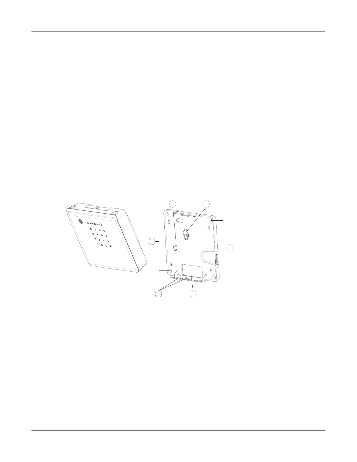
To wall-mount the Panel:
1. Select a permanent location near a power outlet. The wall should be flat and free from vibration and shock.
2. If cables are to be surface run, remove the two breakaway tabs from the bottom of the mounting plate. Otherwise,
pass the Ethernet and AC cables through the opening in the back of the mounting plate.
1. Mounting Location
2. Orientation Guide
3. Tamper Bracket
4. Cable Opening
5. Breakaway T abs
Figure 2-2 Mounting Bracket
3. Position the mounting plate on the wall then mark the 4 screw locations.
4. Fasten the mounting plate to the wall using the supplied hardware.
5. If necessary, remove the battery access cover on the back of the iotega and insert the battery. See Battery Replacement for details.
6. Connect the Ethernet cable and AC adapter to the ports on the back of the panel.
7. Insert the bottom of the iotega into the mounting bracket, then press the top in until it clicks into place. If surface-running the cables, ensure they are channeled through the knock-out openings on the mounting plate.
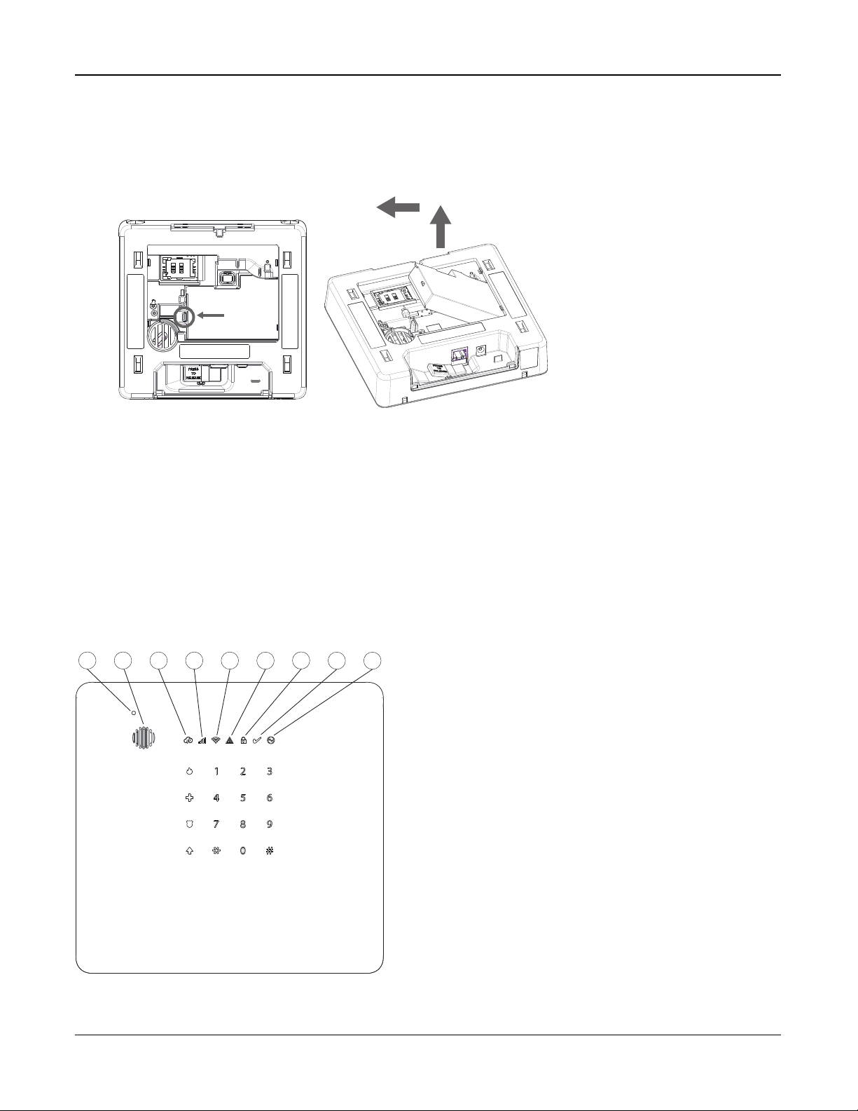
Battery Replacement
Note: When replacing the battery, use battery pack suitable for the application. Refer to on page4.
To remove the battery:
- 8 -
Page 12
Section 2: Installation
Push tab
to
release
1
2
3
4
5
6
7
8
9
1. Detach the iotega from the mounting plate by inserting a flat blade screwdriver into the slots on top of the plate and
gently prying.
Disconnect the AC and Ethernet cables from the iotega.
2. Remove the access cover from the back of the panel.
3. Push the battery retention tab in the direction of the arrow in Figure 2-3 .
4. Lift the battery from the front, then pull up and slide out.
Figure 2-3 Batt ery Removal
To Install a new battery:
1. Insert the battery, back end first.
2. Press the front of the battery down until the retention tab clicks into place.
3. Replace the back cover of the panel.
2.2 Controls and Indicators
The iotega provides a series of LED indicators to notify users of system status.
Figure 2-4 LED Indicators
1. Microphone
2. Siren
3. Remote Connection LED
4. Cellular Signal Strength LED
5. WiFi Signal Strength LED
6. Trouble LED
7. Armed LED
8. Ready to Arm LED
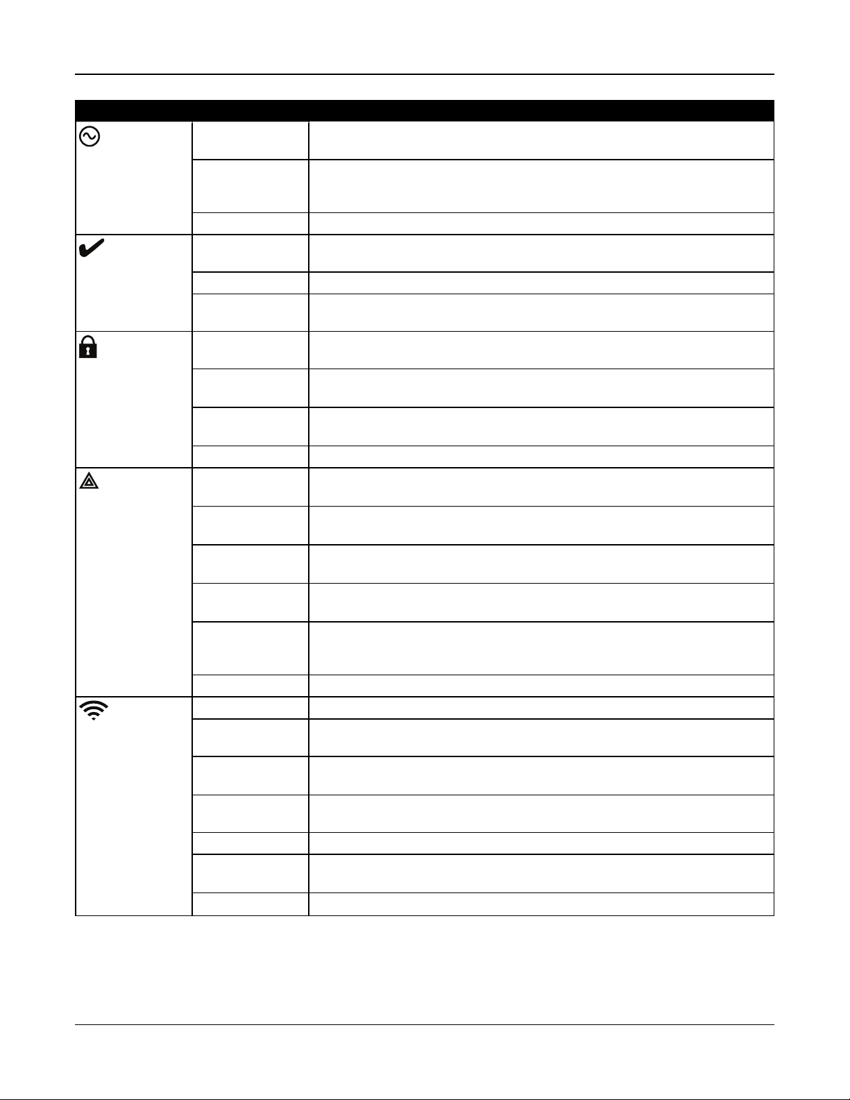
Table 2-1 LED Indicator Operation
9. Power LED
- 9 -
Page 13
Section 2: Installation
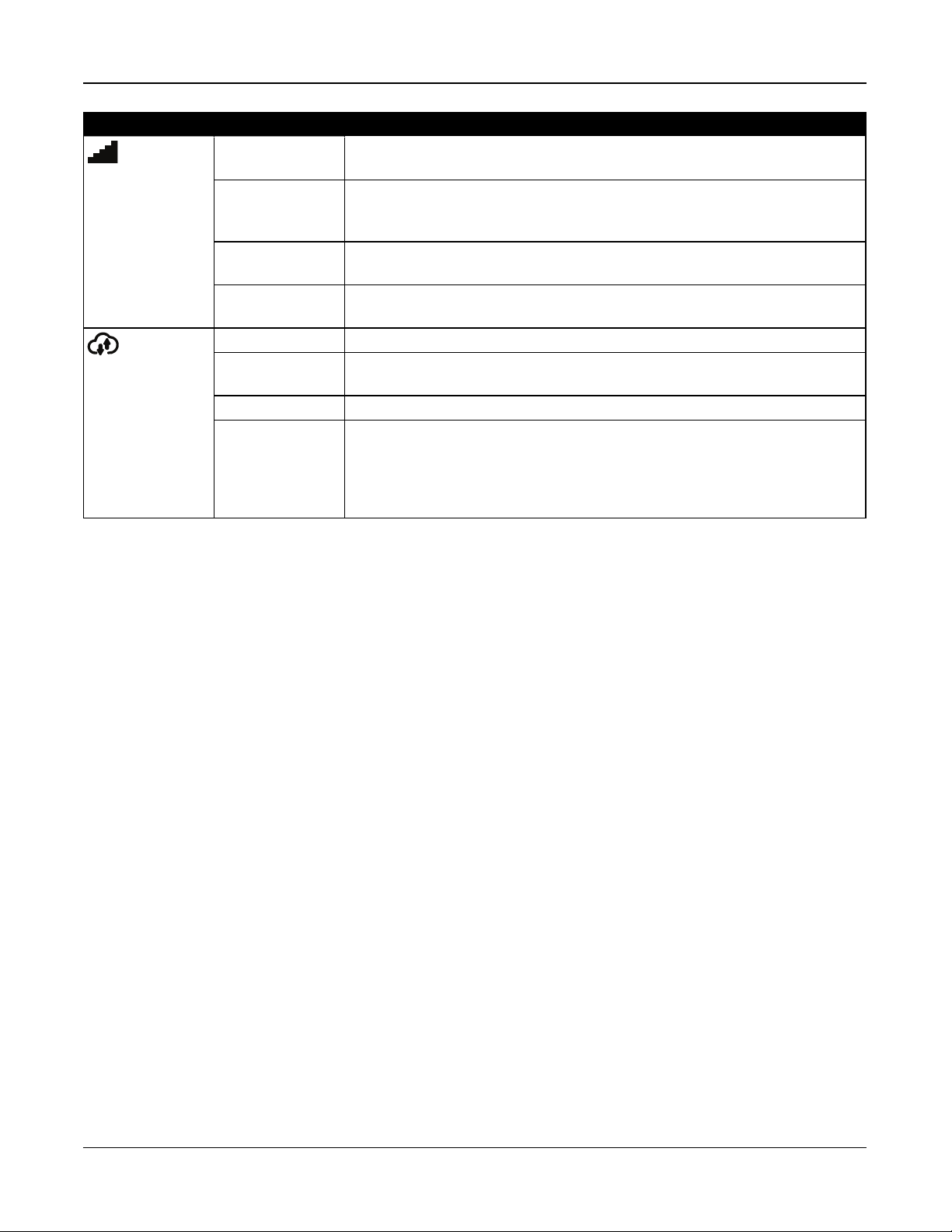
LED Indicator Description
Power ON Steady
[Green]
OFF · System is not powered On
Flashing System test in progress (Ready, Trouble and Arm LED’s flashing at same time)
Ready ON Steady
[Green]
OFF Partition is not ready to arm. Not all zones are secure or an alarm is present.
Flashing [Green] Installer Walk Test (Ready, Trouble and Arm LED’s flashing at same time) or sys-
Armed ON Steady
[Red]
Flashing
[Red]
Flashing
[Red]
OFF Partition is disarmed or audible alarm annunciation is deactivated
Trouble ON Steady
[Amber]
Single flash
[Amber]
Two flashes
[Amber]
Three Flashes
[Amber]
Flashing
[Amber]
OFF No system troubles
Wi-Fi Signal
Strength
ON Steady [Green] Strong Signal Connection
ON Flashing
[Green]
ON Steady
[Amber]
ON Flashing
[Amber]
On Steady [Red] No Signal
Flashing
[Amber]
OFF WiFi disabled
AC power is connected to the system
· NO AC connected, and system is operating on backup battery
· NO AC connected and backup battery is discharged
Partition is ready to arm
tem test in progress (Ready, Trouble and Arm LED’s flashing at same time)
Partition is armed
System in Alarm. [Note: this LED does not flash for silent alarms or panic alarms]
Installer Walk Test (Ready, Trouble and Arm LED’s flashing at same time) or system test in progress (Ready, Trouble and Arm LED’s flashing at same time)
System trouble is present
[*][2] System Trouble menu level 1
[*][2] System Trouble menu 2
[*][2] System Trouble menu 3
Access code is required to view Trouble menu, Installer Walk Test (Ready,
Trouble and Arm LED’s flashing at same time) or a system test is in progress (
Ready, Trouble and Arm LED’s flashing at same time)
Wi-Fi active in WSA mode (for AP mode)
Radio active with weak signal connection
Z-Wave is active in learn pair mode
System Test (AC, Ready, Trouble, Arm LED’s, WiFi Trouble, Cellular Trouble &
System Remote Status flashing at same time)
- 10 -
Page 14
Section 2: Installation
LED Indicator Description
Cellular Sig-
ON Steady [Green] Strong signal connection
nal Strength
Remote Con-
nection Status
Note: During a system test, all LEDs flash.
ON Steady
[Amber]
ON Steady
[Red]
Flashing
[Amber]
ON Steady [Green] Link to remote server is active
ON Flash
[Red]
OFF Link to remote server is not active or
Flashing
[Amber]
Weak signal connection
No Signal or no connection
System Test (AC, Ready, Trouble, Arm LED’s, WiFi Trouble, Cellular Trouble &
System remote status flashing at same time)
Link to remote server is active but has failed to communicate
System Test (AC, Ready, Trouble, Arm LED’s, WiFi Trouble, Cellular Trouble &
System Remote Status flashing at same time)
Note: If the Remote Connection status LED flashes red, the panel may be having
difficulty connecting to the remote server. Restarting the panel may remedy the
issue. If the problem persists, contact technical support
Reset Button
Pressing and holding the Reset button, located under the battery cover (see figure 3-3), for a minimum of 10 seconds performs a vendor reset. WiFi configurations (client mode) are returned to default settings.
Pressing and holding the Reset button for a minimum of 20 seconds returns the following options to their default settings:
SSID, security key, security type and reconnection to DHCP.
Note: The system must be disarmed with no alarms in memory in order for the Reset button to function as described above.
Tamper Switch
The panel includes a tamper switch under the back battery cover. If the battery cover is removed while the system is disarmed, the tamper condition must be cleared before arming is permitted. If the battery cover is removed while the system is
armed, the bell sounds, a system tamper is logged and communicated to the central monitoring station, and a system temper trouble is displayed in the Trouble menu.
Low Power Operation
In the event of an AC power outage, all Wi-Fi and home automation functions are discontinued. The panel uses battery
power to communicate alarms or critical conditions.
2.3 Enrolling Wireless PowerG Security Devices
Device enrollment and configuration is done using the installer portal.
Wireless devices are enrolled using one of the following methods:
l Manually entering a device-specific serial number then configuring the available options.
l Using auto enrollment.
To auto enroll:
1. Enable auto enroll using the installer portal.
2. Power up the wireless device and press the Enroll button until the on-board LED lights steady. The serial number is
displayed.
3. Confirm you want to enroll the device then configure the available options.
- 11 -
Page 15

Section 2: Installation
4. Submit the settings to finish enrollment.
5. Continue the above process until all devices are enrolled.
To manually enroll:
1. Enable manual enrollment using the installer portal or app
2. Add the device zone type, partition, name, and electronic serial number (ESN).
3. When on site, power up the device. Note that some devices need to be tampered to complete enrollment. Refer to the
installation instructions provided with the device for more information.
The wireless devices in the table below each have a dedicated Enroll button, located on the circuit board inside the plastic
casing. A Phillips screw must be removed on most devices to gain access. Refer to the installation instructions provided
with the device for more information.
PGx901 Indoor siren PGx924 Curtain motion detector
PGx904 PIR/Pet I mmune motion detector PGx926 Smoke detector
PGx914 PIR/Pet I mmune motion detector PGx935 Shock detector and magnetic c ontact
PGx905 Temperature detect or PGx944 Tower Cam motion detector
PGx911 Outdoor siren PGx945 Magnetic contact with Aux.
PGx913 CarbonMonoxide detect or
Note: enrolls automatically on power-up
PGx912 Glassbreak detector PGx975 Magnetic contact (vanishing)
PGx916 Smoke and heat detector PGx984 Mirror PIR motion detector
PGx920 Wireless repeater
Note: hold Enrollbutton until red and green LEDs light steady
PGx922 Glassbreak detector PGx994 Outdoor PIR motion detector
PGx974 Mirror PIR with anti-masking
PGx985 Flood detect or
To enroll wireless keys:
PGx929/PGx9394-button wireless key Press and hold [*] button until LED lights s teady then release.
PGx949 2-button wireless key Press and hold unlock button until LED lights steady then release.
PGx938 Panic key Press and hold button until LED lights steady then release.
- 12 -
Page 16

Section 3: Operation
Section 3: Operation
This section describes how to use the iotega‘s integrated keypad.
3.1 Using the Integrated Keypad
The iotega includes a built-in, touch sensitive keypad that activates by proximity. From the keypad, users can arm and disarm the system, view system troubles, and activate the Fire (F), Auxiliary (A) and Panic (P) keys.
The integrated keypad can be configured to work on any partition.
Figure 3-1 Keypad - Normal Operating Mode Figure 3-2 Keypad - Shift Mode
3.1.1 Key Functions
The following keys are enabled during normal operating mode:
Key Description
(0-9)numeric entry (access code)
# clear entries, return to previous screen
* [*] 2 for Troubles, see "Viewing Troubles from the Integrated Keypad" on page 46.
[*] 8 to enable WiFi access point (to add IP devices, i.e.,touchscreen keypad). See "WPS Mode ([*]8)" for more information.
↑ Shift mode switches between numeric and Emergency keys
3.1.2 Emergency Keys
The Fire, Auxiliary and Panic keys can be enabled independently by the installer. All three are enabled by default. The
Emergency keys behave as follows:
Key Alarm Type Indication Reporting Code
Fire Keypad beeps 3 times. Siren sounds. Signal sent to monitoring station Fire Alarm (if pro-
grammed)
Auxiliary Keypad beeps 3 times when activated and 10 times when the event is suc-
cessfully received by the central monitoring station.
Auxiliary alarm
- 13 -
Page 17

Section 3: Operation
Panic Keypad beeps three times and a signal is sent to the monitoring station.
Can be configured as audible or silent
To use the Emergency keys:
1. Press the Shift key (↑). The Emergencykeys are illuminated (if enabled ). If an Emergency key is not pressed within
10 seconds, the keypad returns to normal operating mode.
2. Press and hold an Emergency key for 2 seconds to activate the alarm.
Panic alarm
3.1.3 WPS Mode ([*][8])
WPS (WiFi Protected Setup) mode activates iotega's WiFi access point to facilitate connection with IP devices, such as the
touchscreen keypad and IP cameras.
To enable WPS mode:
1. At the installation site, tap [*] 8 on the integrated kaypad.
2. Enter a valid installer code. The WiFi signal strength LED flashes for two minutes to indicate the system is in WPS
mode.
The WPS window expires after 2 minutes.
3.1.4 Local Webpage ([*][8])
This mode is used to connect the iotega to the local WiFi router, configure static/dynamic ip address, configure WiFi settings
and to view panel, cellular status/information and firmware versions.
Note: WLAN Client Mode and Access Point must be enabled to use this feature.
The access window expires after 10 minutes.
To enable Local Webpage mode:
1. At the installation site, tap [*] 8 on the integrated kaypad.
2. Enter a valid installer code. The WiFi signal strength LED flashes for two minutes to indicate the system is in local
webpage mode.
To access the local webpage:
1. On your local device (mobile/laptop), locate the Guest AP network and join.
2. Enter your password (installer code twice. e.g., 55555555).
3. Use a web browser to access http://iotega.
Note: The access window timer can be restarted by pressing [*][8][installer code] again.
3.2 Arming and Disarming Methods
This section describes the arming methods available on the iotega.
3.2.1 Away Arming
Away Arming arms the entire system, including the perimeter and interior devices. The Ready light must be on to arm the
system. If the Ready light is off, ensure all protected doors and windows are secure or bypassed.
To arm the system, enter a valid access code. To disarm, enter a valid access code.
During exit delay, the Armed and Ready indicators turn on and the keypad beeps once every second during the exit delay
(and three times a second during the last 10 seconds) to alert the user to leave via a delay zone. The Ready light turns off
when the Exit Delay ends.
When the exit delay has expired, the system is armed as indicated by the following conditions:
l the Ready indicator turns off.
l the Armed indicator stays on.
l the panel is silent.
Note: In Away Arming mode, bypassed zones are logged and communicated to the central monitoring station.
3.2.2 Stay Arming
Note: Requires at least one zone defined as Interior Stay/Away or Delay Stay/Away for this function to work.
- 14 -
Page 18

Section 3: Operation
Stay Arming is intended to arm the perimeter of the premises while permitting movement within. The Ready light must be on
to arm the system. If the Ready light is off, ensure all protected doors and windows are secure or bypassed. To Stay arm the
system, enter a valid user code and stay within the premises (do NOT violate a zone programmed as Delay). The Armed
light turns on once a function key is pressed or an access code is entered. The Ready indicator turns off and the Armed
indicator turns on when the exit delay ends.
Note: In Stay Arming mode, all bypassed stay/away zones are logged and communicated to the central monitoring station.
3.2.3 Quick Arming
Quick arming enables users to arm the system via touchscreen or wirefree keypad without entering an access code. This
provides a fast method of arming for regular users and allows users without an access code to arm the system. The Quick
Arming feature must be enabled in order for this function to operate. See "Quick Arm" on page 30.
3.2.4 Disarming
The user must enter through a door programmed as Delay. Upon entering, the panel emits a steady entry delay tone (and a
pulsing tone during the last 10 seconds of entry delay) to alert the user to disarm the system. To disarm the system, enter a
valid user code or use a wireless key. If an alarm occurred while the panel was armed, the keypad numbers corresponding
to the violated zones are illuminated. If the system is disarmed using a method other than the keypad (e.g., wireless key),
the panel emits three squawks to indicate alarm in memory.
- 15 -
Page 19

Section 4: Programming Options
Section 4: Programming
Options
This section provides descriptions of all alarm controller
options, both programmable and read-only. Programming
options are accessed through the Installer portal.
4.1 Integrated Keypad Options
This section describes programmable options for the
iotega’s integrated keypad.
Keypad Lockout Attempt
Keypad Lockout is a security measure designed to prevent
unauthorized attempts to access the security system by limiting the number of attempts to enter a valid access code.
Once the maximum number of attempts is reached, no functions can be performed on the keypad for 5 minutes (Lockout Duration).
If the maximum number of invalid attempts is not reached
within one hour, or if a valid access code is entered, the
counter is reset.
Default: 0 (disabled)
Valid range: 0 t o 255
Keypad Partition Assignment
This section is used to select the partition that the built-in
keypad will operate on.
Default: 1
Valid range: 1-2
Fire Button Options
This function is used to enable or disable the Fire [F] button
on the integrated keypad. When enabled, pressing and holding the [F] button for 2 seconds triggers a Fire alarm. The system sounds 3 beeps to acknowledge the valid alarm and the
siren sounds with a pulsing tone. An alarm reporting code is
transmitted to the central monitoring station.
Default: Enabled
Valid range: Enabled, Disabled
Auxiliary Button Options
This function is used to enable or disable the Auxiliary [A]
button on the integrated keypad. When enabled, pressing
and holding the [A] button for 2 seconds sends an emergency alarm reporting code to the central monitoring station.
When the emergency reporting code is received, the keypad
beeps 10 times.
Default: Enabled
Valid range: Enabled, Disabled
Panic Button
This function is used to enable or disable the Panic [P] button on the integrated keypad. When enabled, pressing and
holding the [P] button for 2 seconds sends an emergency
alarm reporting code to the central monitoring station.
Default: Enabled
Valid range: Enabled, Disabled
Internal Buzzer Control
This option is used to set the tone of the internal buzzer. The
tnoe ranges from lowest (1) to highest (15). Programming (0)
turns off the buzzer.
Default: 7
Valid range: 0-15
Keypad Lockout Duration
This section displays the length of time that the integrated
keypad remains locked after the programmed number of
access code attempts has been exceeded.
Default: 5 minutes
Valid range: Read-only
Quick Arming /Function Key
When this option is enabled, [*][0] arming and Stay/Away
function keys may be used to arm the system without entering a valid access code.
When this option is disabled, [*][0] arming is not permitted.
All arming functions require the entry of an access code to
activate (including Stay/Away keys).
Default: Enabled
Valid range: Enabled/Disabled
Keypad Blanking
When this option is enabled, if no keys are pressed for 30
seconds, all keypad lights except backlighting (if enabled)
are shut off until the next keypress, entry delay, audible
alarm or keypad buzzer condition.
Keypad function keys still operate when the keypad is blank,
unless the function key is programmed to require an access
code. Keypad Blanking While Armed overrides this feature.
When a partition is armed and in alarm, entering a code to
remove blanking silences the alarm and disarms the system.
When this option is disabled, the keypad lights remain on at
all times.
Default: Enabled
Valid range: Enabled/Disabled
Ready LED Flashes for Force Arm
When this option is enabled, if a force arm capable zone is
tripped, partition keypads flash the ready LED in the disarmed state instead of illuminating it steadily. If a non-force
arm-capable zone is tripped, the ready LED turns off.
- 16 -
Page 20

Section 4: Programming Options
When this option is disabled, if a force arm capable zone is
tripped, the Ready LED is illuminated steadily. If a non-force
arm capable zone is tripped, the Ready LED turns off.
Default: Enabled
Valid range: Enabled/Disabled
Temperature in Celsius
When this option is enabled, temperature is displayed in
Celsius on LCD keypads.
When this option is enabled, temperature is displayed in
Fahrenheit on LCD keypads.
Default: Celsius
Valid range: Celsius/Fahrenheit
4.2 System Configuration Options
This section describes programmable options for the alarm
controller.
System Area Label
Use this option to program a custom label for the security
system. This label is used in the event buffer when system
events occur.
Default: System Area
Valid range: 32 Characters
System Account Number
The system account number is used to identify the alarm system when communicating system events to the central monitoring station. The system account number can be either 4
or 6 digits long. Program a 6-digit code only when using the
SIA reporting format. SIA uses this account number for all
partitions and system events. All other reporting formats use
a 4-digit system account number to report system maintenance (e.g., low battery, zone fault) and test transmission
events. To program a 4-digit system account number, enter
4 digits followed by FF.
Note: This field is mandatory for communication with the
central monitoring station.
Default: F FFFFF (disabled)
Valid range: 000001 t o FFFFFF (Hexadecimal)
Event Reporting Format
This programming option is used to assign a communicator
format for transmitting zone alarms, tampers, faults and other
signals to the central monitoring station.
The following communicator formats are available:
Con tact ID
Each of the digits indicate specific information about the signal. For example, if zone 1 is an entry/exit point, the event
code contains [34]. The central monitoring station would
receive the following:
*BURG - ENTRY/EXIT - 1 where the “1” indicates which
zone went into alarm.
SIA Format - Level 2 (Hard Co ded )
The SIA communication format used in this product follows
the level 2 specifications of the SIA Digital Communication
Standard - October 1997. This format sends the account
code along with its data transmission. The transmission
appears similar to the following at the receiver:
N ri1 BA 01
N = New Event
ri1 = Partition /Area Identifier
BA = Burglary Alarm
01 = Zone 1
A system event uses the Area Identifier ri00.
Default: SIA
Valid range: SIA, CID
Bell Squawk on Arming
With this option enabled, the iotega chirps the sirens briefly
at full volume when the system is successfully armed. The
following options are provided to customize this option:
None: Sirens do not chirp when the system is armed.
All RF: Sirens chirp when armed by any wireless device.
RF Wireless Key: Sirens chirp only when armed by a wireless key.
RF Keypad: Sirens chirp only when armed by a wirefree
keypad.
Default: RF Wireless Key
Valid range: None, All RF, RF Wireless Key, RF Keypad
Chime on Zone Opening
When this option is enabled, the door chime sounds each
time an appropriately configured zone is opened.
The Door Chime attribute must be set to ON for every zone
that requires a chime on opening.
Default: Enabled
Valid range: Enabled, Disabled
Chime on Zone Closing
When this option is enabled, the door chime sounds each
time an appropriately configured zone is closed.
The Door Chime attribute must be set to ON for every zone
that requires a chime on opening.
Default: Disabled
Valid range: Enabled, Disabled
Trouble Beeps (Audible/ Auto-silent)
When this option is enabled, trouble beeps are not sounded
for any trouble condition except Fire/CO. For these, trouble
beeps sound every 10 seconds for the duration of the
trouble.
When this option is disabled, the system announces
- 17 -
Page 21

Section 4: Programming Options
troubles through the keypad buzzer every 10 seconds.
Pressing any key on the keypad silences the trouble beeps;
however, new troubles will restart trouble beeps. For
troubles that have been silenced but are still present, trouble
beeps restart daily at 7AM.
Default: Enabled
Valid range: Enabled, Disabled
Burglary Bell Time-out
This option determines the length of time the system siren
sounds for. System tampers follow this timer, but Fire alarms
and keypad buzzers do not.
Default: 4 Minutes
Valid range: 0 t o 255 Minutes
Fire Bell Time-Out
This option determines the maximum activation time for fire
alarm sirens. Each partition has a dedicated Fire Bell Timeout timer.
Fire Bell Time-out takes priority over Burglary Bell Time-out.
Default: 5 Minutes
Valid range: 0 t o 255 Minutes
Audible Wireless Device Fault
When this option is enabled and the system is armed, wireless zone faults cause the siren to sound. The following
zone types do not generate an alarm when in fault during
stay arm mode: interior stay away zone, delay stay away
zone, instant stay away zone, night zone. The following
zone types do not generate an audible alarm in any armed
mode (stay, away, or night): 24-hour supervisory, 24-hour
non-alarm, 24-hour CO, delayed 24-hour Fire, standard 24hour fire, Auto-verified fire.
When the partition is armed, wireless supervisory troubles
from sirens, keypads and repeaters generate audible alarm
conditions.
If Tamper/Fault Detection is enabled, these events start the
burglary verified timer and affect the burglary verified
counter.
OFF: Wireless zone faults do not sound the siren.
Default: Disabled
Valid range: Enabled/Disabled
Audible Panic
This option is used to set internal buzzer behavior when the
Panic key is pressed. When set to Audible, pressing the
Panic key causes the buzzer to sound a series of 3 beeps to
acknowledge the alarm. The buzzer then sounds a steady
tone for the length of the bell time-out or until an access
code is entered.
When set to Silent, pressing the Panic key causes the
buzzer and the bell output to remain silent, but the alarm is
still transmitted (if programmed).
Default: Silent
Valid range: Audible, Silent
Remote Reset
When this option is enabled, if an alarm occurs on a burglary zone, the system is locked out after disarming. It
remains locked until a 5-digit reset code, provided by the
installer/central station, is keyed in. If a duress code is used
to disarm the partition, the system is not locked out.
In the disarmed state, only Audible 24 Hour Burglary zones,
Audible 24 Hour Latching Tamper zones, and Audible 24
Hour zone cause lockout.
To obtain the reset code, the user must provide a corresponding system lock code, displayed on the keypad
when one of the following conditions occurs:
l the system has been disarmed (Duress Code
excluded)
l the bell has timed out (24Hr zones)
l an access code has been entered (24Hr zones)
On an LCD keypad, the message “REMOTE RESET RQD” is
displayed on the top line and “CODE” along with the actual
code is displayed across the bottom line.
On an LED keypad, the reset number is scrolled across the
screen.
While the system is locked out, only [*][3], [*][6], [*][7], and [*]
[8] are available. Accessing [*][8] Installer Programming
unlocks the alarm system. The system continues to function
(alarms, tampers, etc) while the system is locked out. Lockout follows both transmission and bell delays.
When this option is disabled, the system is not locked out
after an alarm occurs.
Note: EU Entry Procedure takes priority over bell delay. If an
alarm occurs during entry delay when EU Entry Procedure is
enabled, the bell sounds immediately.
Default: Enabled
Valid range: Enabled/Disabled
Remote Reset Follows Sequential Detection
When this option is enabled, remote reset is only required
after disarming if a sequential detection alarm was generated and logged in the previous armed state.
When disabled, any burglary alarm requires remote reset
after disarming the partition.
Default: Disabled
Valid range: Enabled/Disabled
EU Entry Procedure
When this option is enabled, if an alarm occurs on a zone
when entry delay is not active, the siren activates and the
alarm is communicated immediately, depending on the zone
type tripped.
When entry delay is active, all burglary type alarms activate
the siren, but communication of the alarm is delayed by 30
seconds. When entry delay expires, the alarm is not
- 18 -
Page 22

Section 4: Programming Options
communicated unless the siren has been active for at least
30 seconds.
Police code is not generated as a result of alarms triggered
during entry delay, although the Burglary Verification Timer
starts after entry delay and the 30-second communication
delay expire.
This feature is only active when the partition is armed.
When this option is disabled, burglary alarms that occur during entry delay activate the siren and are communicated
immediately. Two exceptions are if the bell delay timer is programmed and if transmission delay is enabled for the zone
in alarm. In both cases, the alarm follows the timer.
Default: Disabled
Valid range: Enabled/Disabled
Troubles Inhibit Arming
When this option is enabled, the following troubles prevent
arming until restored:
l Tampers on the system, modules and zones
l AC troubles on the system and modules
l Battery troubles on the system and zones
l Transmission troubles (FTC, GPRS, Ethernet)
The alarm system can still be armed if troubles are overridden. To perform a trouble override, while in the Trouble
Menu ([*][2]), scroll right or left and press [*] when Trouble
Acknowledgment is displayed on the keypad. Alternatively,
press the [9] key to acknowledge and override the existing
troubles.
To override open zones, faulted zones or tampered zones,
use the Zone Bypass feature.
Note: When this option is disabled, the system can be
armed even when troubles are present.
Note: When Engineer’s Reset is on, trouble conditions cannot be overridden. Zone Expander supervisory troubles cannot be acknowledged and overridden. These conditions
must be restored before the panel can be armed.
Default: Disabled
Valid range: Enabled/Disabled
Open Zones Cancel Arming
When this option is enabled, the system cannot be armed
while zones are open unless a valid access code is entered.
In order to bypass open zones, the bypass attribute must be
enabled for the zone.
When this option is disabled, open zones do not prevent
arming.
Default: Enabled
Valid range: Enabled/Disabled
Engineer’s Reset (EU)
When this option is enabled, if the system has gone into
alarm during the previous armed period, or if a 24-hour
alarm has occurred (armed or disarmed), the system cannot
be armed (Ready light OFF) until Installer Programming is
entered or Engineer’s Reset is performed via DLS. “Reset
Required” is displayed on the keypad. This feature also
applies to tampers and faults in both armed and disarmed
states and does not apply to module tampers, system supervisory alarms, zone expander alarms.
Note: If Engineer’s Reset is triggered during exit delay, the
system still arms. Troubles cannot be overridden while
Engineer’s Reset is enabled.
When this option is disabled, the system does not require
Engineer’s Reset or to be placed into Installer Programming
in order to arm the system after an alarm.
Default: Disabled
Valid range: Enabled/Disabled
Tamper/Fault Detection
When this option is enabled, the following trouble conditions, when configured to generate audible alarm conditions, contribute to a burglary verification sequence when
sequential detection is used. Bell circuit trouble also generates an audible alarm condition using other sirens
assigned to the partition.
l Bell circuit trouble
l Zone fault
l Module supervisory trouble
l Alternate Communicator fault
l Ethernet Trouble
When this option is disabled, trouble conditions are displayed and processed as per standard operation.
Default: Disabled
Valid range: Enabled/Disabled
EU Sequential Detection
This option is enabled by setting Burglary Verification Selection to Sequential Detection. Sequential detection is used in
applications where various trouble conditions, classified as
sabotage conditions, can contribute to a confirmed alarm
condition. The burglary verification timer is in minutes.
The features related to this operation are:
l Burglary Verification Zone Attribute
l Transmission Delay Zone Attribute
l Burglary Verification Counter
l Burglary Verification Selection
l Burglary Verification Timer
l Transmission Delay
This feature is meant for use with the EU entry procedure
instead of the normal Police Code or Cross Zoning features.
For Europe, sabotage (tamper) events must contribute to a
verified burglary alarm and the bell must activate for all
alarm conditions.
Default: Enabled
Valid range: Enabled/Disabled
- 19 -
Page 23

Section 4: Programming Options
Burglary Verification Selection
Use this section to select one of the following burglary verification timer modes:
001 Police Code The Burglary Verification Timer operates in
minutes
002 Cross Zoning The Burglary Verification Timer operates in
seconds. The first alarm in t he s equence
does not log or communicate the alarm or
activate the bell.
003 Sequential Detection TheBurglary Verification Timer operates in
minutes. The first alarm in the s equence
causes an audible bell.
Burglary Verification Counter
This option is used to program the number of zone activations required to verify an alarm.
Default: 002
Valid range: 000 to 255
Burglary Verification Timer
If more than one zone with the Burglary Verification attribute
enabled is tripped within the duration of this timer, a burglary
verified event is communicated and logged. "Burglary Verified" is displayed on the keypad when the system is disarmed.
Default: 060 minutes
Valid range: 000 to 255 minutes
Default Master Code
This function is used to reset the master code to factory
default. When this is done, the master user is notified via
email or text if configured.
Default Master Code is available through the installer portal
only.
Access Code Required For Bypassing
When this option is enabled, an access code is required to
view the zone bypass menu.
When this option is disabled, the zone bypass menu is
accessible to anyone.
Default: Disabled
Valid range: Enabled/Disabled
RF Jam
When this option is enabled, the alarm panel detects and
reports continuous wireless signals that could interfere with
the operation of the alarm system.
Default: Disabled
Valid range: 00: Disabled, 01: UL 20/20, 02: EN 30/60, 03: Class 6 30/60
Installer Access Window Permission
When this option is enabled, the installer is given access to
the panel’s programming sections for a 4-hour window, or
until the install has been finalized.
When this option is disabled, the installer can access the
panel’s programming sections at any time.
This option is controlled by Level 1 users.
Default: Enabled
Valid range: Enabled, Disabled
Ethernet IP Address
This is the resolved value based on the DHCP address
assignment.
Default: 000.000.000.000
Valid range: Read-only
Ethernet IP Subnet
This is the resolved value based on the DHCP address
assignment.
Default: 255.255.255.000
Valid range: Read-only
Gateway IP Address
This is the resolved value based on the DHCP address
assignment.
Default: 000.000.000.000
Valid range: Read-only
DNS 1 IP Address
This is the resolved value based on the DHCP address
assignment.
Default: 000.000.000.000
Valid range: Read-only
DNS 2 IP Address
This is the resolved value based on the DHCP address
assignment.
Default: 000.000.000.000
Valid range: Read-only
Access Code Required to View/Silence Troubles
This option is used to enable and disable the need to enter
an access code before viewing and silencing system
troubles.
Default: Disabled
Valid range: Enabled, Disabled
Cellular Low Signal Trouble
This option is used to determine if the system will generate a
trouble event when a weak cellular signal is detected.
When enabled, a trouble event is generated if the radio signal level falls below threshold level (average CSQ level 4 or
less).
Default: Enabled
Valid range: Enabled, Disabled
- 20 -
Page 24

Section 4: Programming Options
Lockout Attempts
This option is used to program the number of invalid access
code entries allowed before the keypad is locked. When
keypad lockout occurs, the system is inaccessible by keypad
for the programmed duration. If the number of invalid
attempts is not reached within one hour, or if a valid access
code is entered, the counter is reset to 0 after 5 minutes.
Each keypad keeps track of its own lockout count and time.
Note: The FAP keys are not locked.
Default: 0
Valid range: 0 t o 255
Fire Supervision
This option is used to control system supervision of smoke,
CO and heat detectors. When this option is enabled, fire
detection devices are monitored over a four-hour period. If a
device fails to report within the four-hour window, a hardware fault trouble is logged for the zone.
With this option disabled, fire detection devices follow the
programmed supervisory window up to a maximum time of
18 hours. After 18 hours, fire detection devices go into fault,
regardless of the programmed supervisory window.
Default: Disabled
Valid range: Enabled/Disabled
Wireless Supervisory Window
Use this option to program the time window for reception of
supervision (keep alive) signals from wireless devices
enrolled on the system. If a device does not report at least
once within the programmed time window, a hardware fault
trouble is generated.
Default: 24 Hours
Valid range: 1 Hour, 2 Hours, 4 Hours, 8 Hours, 12 Hours, 24 Hours, Disabled
Wi-Fi Low Signal Trouble
This option is used to determine if the system will log and
report low Wi-Fi signals.
Default: Enabled
Valid range: Enabled, Disabled
Communication Cancel Window
This option is used to program the length of the Communication Cancel window.
Entering an access code during the communicaiton cancel
window sends a code to the central monitoring station,
informing them that the previous event should be disregarded.
The communications cancel window begins after the transmission delay expires and a zone alarm is transmitted. If an
access code is entered during this window, a reporting code
is communicated and logged. If the window expires without
an access code entry or a code is entered after the window,
the communications canceled event is not logged or communicated.
Note: The cancel window does not start after an Emergency
key alarm.
Default: 0 Minutes (Standard)
Valid range: 0 to 255 Minutes (Standard)
Swinger Shutdown
This value defines the number of communication attempts
made before the event goes into swinger shutdown. Once
the programmed number of alarm/restore events have been
communicated for an event, no further alarm/restore events
are sent until swinger shutdown is reset. The last restore
event is not communicated until swinger shutdown is
cleared.
Default: 003 (Standard)
Valid range: 000-014 (Standard)
Communication Delay
This value defines the delay before an alarm is transmitted.
The delay is for zones which have the Transmission Delay
attribute enabled. Each partition shares the same active
timer. If the delay is already active due to an alarm on a different partition, any new activity on another partition does
not restart the communications delay timer. Burglary Verified
events are postponed until after the transmission delay
expires. When a valid disarming procedure is used while the
transmission delay is active, a communications canceled
message is briefly displayed on the keypad when the delay
is canceled.
Default: 000 (Standard)
Valid range: 000-255 Seconds (Standard)
AC Failure Communication Delay
This value determines the delay before an AC failure or
restore is logged and reported. The AC failure or restore is
still displayed immediately in the Trouble menu.
Default: 030Minutes
Valid range: 000to 255 Minutes
Wireless LowBattery Communication Delay
When a zone reports a low battery condition, the trouble is
indicated immediately in the Trouble menu, but transmission
to the monitoring station and logging to the event buffer is
delayed by the number of days programmed in this section.
If the low battery condition is not corrected before the delay
expires, the condition is transmitted and logged to the event
buffer. The Low Battery Restore transmission is not delayed.
Default: 007 days
Valid range: 000 to 255 days
[A] Key Alarm control (for 2-way Voice) - Read Only
When this option is enabled, a 2-way talk/listen-in session is
initiated when the Auxiliary [A] key is tapped.
- 21 -
Page 25

Section 4: Programming Options
Default: Enabled
Valid range: Enabled
[P] Key Alarm Control (for 2-way Voice) - Read Only
When this option is enabled, a 2-way talk/listen-in session is
initiated when the Panic [P] key is tapped. Note that the [P]
key must be programmed as audible in order to initiate 2way audio. If the [P] key is programmed as silent, a listen-in
only session is initiated when the Panic [P] key is tapped.
Default: Enabled
Valid range: Enable
Duress Alarm Control (for 2-way Voice) - Read Only
When this option is enabled, a Listen-in session is initiated
when a Duress alarm occurs.
Default: Enabled
Valid range: Enabled
Wireless Siren Control During 2-way Voice
When this option is enabled and an audible alarm is
present, the wireless siren activates during a 2-way audio
session.
When disabled, the wireless siren is silent when a 2-way
audio session begins. This allows the user to better hear the
operator. The sounder resumes operation for the timeout duration if the panel has not been disarmed at the end of the 2way session.
Default: Enabled
Valid range: Enabled, Disabled
New Alarms Disconnect 2-Way Audio
When this option is enabled, a listen in/2-way audio session
in progress is disconnected in favor of the incoming alarm.
This option is useful when using a 2G network, as voice (2way audio) and data (alarm) sessions cannot take place at
the same time.
Note: Fire/CO alarms override this option and force a disconnect (if necessary) in order to communicate the event.
When this option is disabled, new alarms do not disconnect
2-way audio. If a new alarm is generated during the first 70
seconds of the two-way voice interval, the monitoring station
operator has 20 seconds to begin another two-way voice
interval.
If the new alarm is generated during the last 20 seconds of
the two-way voice interval, the monitoring station operator
has the remainder of the interval to begin another two-way
voice interval.
Default: Disabled
Valid range: Enabled/Disabled
12/24 Hour Clock
When this option is enabled, time is displayed in 24-hour
clock format.
Default: Enabled
Valid range: Enabled/Disabled
4.2.1 Reporting Configuration Options
Open/Close
When this option is enabled, the following open/close
events are reported to the central monitoring station when
they occur. When disabled, open/close events are not reported.
l Away Arming (Close)
l Stay Arming (Close)
l Disarm (Open)
l Special Closing
l Auto Arming
l No Activity Arming
l Auto Arm Cancel Postponed
Default: Enabled
Valid range: Enabled/Disabled
Special Alarm Comms
When this option is enabled, the following special alarm
events are reported to the central monitoring station when
they occur. When disabled, special alarm events are not
reported.
l Exit Error
l Recent Closing
l Local keypad Lockout
l Remote Lockout
Default: Enabled
Valid range: Enabled/Disabled
Maintenance
When this option is enabled, the following maintenance
events are reported to the central monitoring station when
they occur. When disabled, maintenance events are not
reported.
l Event Buffer Full
l Close Delinquency
l Cold Start
l Installer Lead In/Out
l FW Update(Begin, Successful, Fail)
Default: Enabled
Valid range: Enabled/Disabled
System-Wide Troubles
When this option is enabled, the following system trouble
events are reported to the central monitoring station when
they occur. When disabled, system trouble events are not
reported.
l AC Loss and restore
l Battery trouble and restore
l Tamper and restore
l Hardware fault and restore
l RF Jam trouble and restore
- 22 -
Page 26

Section 4: Programming Options
l RF Delinquency
l Loss of time trouble and restore
l Supervisiontrouble and restore
l Not networkedtrouble and restore
l Fire/CO trouble and restore
l Tamper trouble and restore
l Receiver not available trouble and restore
l FTC trouble and restore
l Receiver supervisiontrouble and restore
l Cellular trouble and restore
l Ethernet/WiFi trouble and restore
l Remote shoutdown trouble and restore
Default: Enabled
Valid range: Enabled/Disabled
Alarms
The following alarm events are reported to the central monitoring station when they occur:
l Zone Alarm (including Heat/Freeze trouble)
l Alarm Cancel
l Duress Alarm
l Opening After Alarm
l Burglary Verified
l Burglary Not Verified
l Emergency Key Alarm
l Recent Closing
Default: Enabled
Valid range: Read-only
Alarm Restoral
When this option is enabled, the following alarm restoral
events are reported to the central monitoring station when
they occur. When disabled, alarm restoral events are not
reported.
l Zone Alarm Restore
l Emergency Key Restore
Default: Enabled
Valid range: Enabled/Disabled
Test
When this option is enabled, the following test events are
reported to the central monitoring station when they occur.
When disabled, test events are not reported.
l System Test
l Installer Walk Test (Begin/End)
Default: Enabled
Valid range: Enabled/Disabled
Bypass
When this option is enabled, the following bypass events
are reported to the central monitoring station when they
occur. When disabled, bypass events are not reported.
l Bypass/Unbypass
l PartialClosing
l
ManuallyBypassed Zones
l Stay Zones
l Force Arm Zones
Default: Enabled
Valid range: Enabled/Disabled
Periodic Test Transmissions
When this option is enabled, the following test transmission
events are reported to the central monitoring station when
they occur. When disabled, test transmission events are not
reported.
l Periodic Test
l Periodic Test with Trouble
Default: Enabled
Valid range: Enabled/Disabled
4.2.2 Network Configuration Options
LAN/WAN Obtain IP Address
This option is used to determine how an IP address for
LAN/WAN communication is obtained. When DHCP is selected, the iotega is automatically assigned an IP address by
the network. When
Static IP is selected, a consistent IP address is used.
Default: DHCP (Automatic)
Valid range: DHCP, Static IP
LAN/WAN IP Address
This section is used to program a static IP address. To use a
static IP address, the option LAN/WLAN Obtain IP Address
must be set to Static IP address.
Default: 000.000.000.000
Valid range: 000.000.000.000to 255.255.255.255
LAN/WLAN IP Subnet Mask
This section is used to program a LAN/WLAN subnet mask.
To use the subnet mask, the option LAN/WLAN Obtain IP
Address must be set to Static IP address.
Default: 255.255.255.255
Valid range: 000.000.000.000to 255.255.255.255
LAN/WLAN Gateway IP Address
This section is used to program the IP address for the network’s default gateway. To use this gateway, the option
LAN/WLAN Obtain IP Address must be set to Static IP
address.
Default: 000.000.000.000
Valid range: 000.000.000.000to 255.255.255.255
Panel's Preferred DNS Server
This section is used to program the name of the preferred
Domain Name System server.
Note: To use the panel’s preferred DNS server, the option
LAN/WLAN Obtain IP Address must be set to Static IP
address.
- 23 -
Page 27

Section 4: Programming Options
Default: 000.000.000.000
Valid range: 000.000.000.000to 255.255.255.255
Panel's Alternate DNS Server
This section is used to program the name of an alternate
Domain Name System server to be used if the preferred
DNS server is unavailable.
Note: To use the panel’s alternate DNS server, the option
LAN/WLAN Obtain IP Address must be set to Static IP
address.
Default: 000.000.000.000
Valid range: 000.000.000.000to 255.255.255.255
WiFi Country Code
This option is used to select the country of operation for the
alarm system.
Default: CA (Canada)
Valid range: US, AU, CA, UK, FR, SE, IL, None
WLAN SSID
This section is used to program a network name (unique
identifier) for the panel.
Default: None
Valid range: Alphanumeric
WLAN Client Control
This option is used to control WiFi client mode.
Default: Enabled
Valid range: Enabled/Disabled
Default: Blank
Valid range: 32 ASCII characters or Null
Panel's Cellular Login User Name
This section is used to program a user name for cellular network connection.
Default: Blank
Valid range: 32 ASCII characters or Null
Panel's Cellular Login Password
This section is used to program a user password for cellular
network connection.
Default: Blank
Valid range: 32 ASCII characters or Null
Time Zone
This option defines the time zone that the alarm system will
operate in.
From the list of valid entries, locate and select the appropriate time zone.
Default: US Eastern
Valid
US-Alaska, US-Aleutian, US-Arizona, US-Central, US-Eastern, US-
range:
Hawaii, US-Indiana-East, US-Indiana-Starke, US-Michigan, US-Mountain, US-Pacific, US-Samoa, CA-Atlantic, CA-Central, CA-Eastern,
CA-Mountain, CA-Newfoundland, CA-Pacific, CA-Saskatchewan, CASaskatchewan-East, CA-Yukon
4.2.3 User Configuration Options
This section describes programming options for configuring
system users.
WLAN Security Type
This option is used to select which encryption protocol the
system uses to secure the wireless network.
Default: WPA2 PSK AES
Valid range: WPA PSK TKIP
WPA PSK AES
WPA PSK TKIP AES
WPA2 PSK TKIP
WPA2 PSK AES
WPA2 PSK TKIP AES
MIXED MODE TKIP
MIXED MODE AES
MIXED MODE TKIP AES
WLAN Security Key
This section is used to program a password for the Wi-Fi network.
Default: None
Valid range: 32 character ACCII
Panel's Cellular Public APN
This section is used to program the Access Point Name of
the network used for cellular-data connectivity.
User Partition Assignment
This section is used to assign system user 2-100 to an available partition. Users may be assigned to multiple partitions.
Basic/Standard users may only assign new users to partitions they themselves have permission to access.
Default: 1
Valid range: 1, 2, 3, 4, All
User Access Code (Pin)
This section is used to program a 4-digit code used to
access the panel. Each user requires a code. Duplicate
codes are not permitted.
Installers do not have the ability to change the Master code,
but can reset it to factory default if necessary. See Default
Master Code.
Default: Blank
Valid range: 0000 to 9999
User Access Level
Each system user is assigned an access level that determines the features they can use. All codes are 4-digit decimal
entries. Duplicate codes are not permitted.
- 24 -
Page 28

Section 4: Programming Options
The following access levels may be available on your panel:
Master User
Has access to all system functionality. These functions
include:
l Bypass/unbypass zones
l Chime enable/disable
l View troubles
l View alarms in memory
l Create new users (via user app)
l Initiate a system test
l Update Panel WiFi (client mode) SSID & password
l Adjust keypad settings sucha as buzzer tone and
volume, display contrast and brightness
l Assign wireless keys to users
Level 0: Professional Installer
Has permission to enable WPS mode (to enable local programming access to the panel via the installer app) and also
initiate phone test.
Level 1: Supervisor/Administrator
Users assigned to this level have similar privileges to the
Master Code user but are limited based on the partition
assignment. This user can perform the following actions on
the partitions they are assigned to:
l Arm/Disarm
l Bypass/Unbypass
l Enable/disable chime
l Access home automation menu
l View troubles, initiate a system test
l Select a display language
l View the event buffer
l Program zone labels
l Schedule auto arming
l Initiate firmware updates
l Update WiFi SSID and password
l Create new users
l Program a duress code
l Program user labels
Supervisor users can only add, edit or delete users
assigned to the same partitions as they are.
Level 2: Basic/Standard User
Has permission to access basic security functions, including:
l Arm/disarm
l Bypass/unbypass zones
l Enable/disable chime
l View system troubles
l View alarm in memory
Level 3: Maintenance/Guest
Users assigned to this level are limited to an assigned partition and have reduced system access. These functions
include:
l Arm/disarm
l Enable/disable chime
l View system troubles
Duress code:
Has access to all features of Basic/Standard user, including:
l Arm/disarm
l Bypass/unbypass zones
When this code is used for any function, a duress code
event will be generated.
User Name (label)
This option is used to program a system user name.
Default: Blank
Valid range: 32 character ACSII
User Enable (Locked)
This option is used to control access to the security system
for the selected user. When enabled, the user can access all
functionality available to their user level. When disabled, the
user is locked out of the system.
Default: Disabled
Valid range: Enabled/Disabled
Installer Access Requires User Permission
When this option is enabled, access to installer configuration settings requires input of a code by the user.
Once the code is entered, a 6-hour window is available to
access panel configuration settings.
The installer has unlimited access to the panel's configuration settings until the account goes live. After that, a
user code is required to access configuration settings if this
option is enabled.
Note: Powering cycling the panel opens the installer access
window.
When this option is disabled, the installer does not require a
user code to access panel configuration settings.
Default: Disabled for EN. Enabled f or UK.
Valid range: Enabled/Disabled
Firmware Update Requires Code
Menu: [*][6][Master Code] > Authorize Update
Keypad: [*][6][Master Code] + 17
This function is used to give authorization to the system to
start the firmware upgrade process after all firmware
upgrade files for the keypads, HSM2HOST, control panel
and alternate communicator have been fully downloaded.
Once this option is activated, the keypads and system automatically exit [*][6] and indicate that the firmware update is in
progress.
4.3 Central Monitoring Station Programming Options
The following section provides descriptions of all programming options for communications between the iotega
and the central monitoring station.
- 25 -
Page 29

Section 4: Programming Options
Communication Path
Use this option to select the method by which the panel communicates to the central monitoring station. Choose one of
the following:
None: The system does not communicate to the central monitoring station via Ethernet or Cellular.
Ethernet: The system communicates to the central monitoring station via Ethernet connection only.
Cellular: The system communicates to the central monitoring
station via cellular connection only.
Ethernet and Cellular: The system communicates to the central monitoring station via Ethernet as the primary path and
cellular as the secondary path.
Default: None
Valid range: None, Ethernet, Cellular, Ethernet and Cellular
CMS Ethernet 1 Account Code
This option is used to program an account code used by the
central monitoring station to identify the ethernet transmitter.
Programming all 0’s or all F’s causes a module configuration trouble.
Note: If both Ethernet Receiver 1 and Cellular Receiver 1
are the same receiver (IP and port number are identical), Ethernet Receiver 1 account is used for Ethernet and Cellular.
Note: An Ethernet account code is necessary in order for the
iotega to communicate to the central monitoring station (if
Ethernet communication path is selected).
Default: 0000000000
Valid range: 0000000000 to F FFFFFFFFF
CMS Ethernet 1 DNIS
The Dialed Number Information Service (DNIS) is used in
addition to the account code to identify the communicator
module at the central monitoring station.
Default: 000000
Valid range: 000000 to 0FFFFF (first digit not used)
CMS Ethernet 1 IP Address
This option is used to program an IP address for the Ethernet receiver. When a valid IP address has been programmed, Ethernet receiver 1 is enabled and will
communicate events over the Ethernet channel.
Ethernet Receiver 1 and Cellular Receiver 1 may be configured to communicate to the same central monitoring station receiver. To configure the device to operate using this
common receiver mode functionality, program Ethernet
Receiver 1 and Cellular Receiver 1, IP address and port
number with identical values.
Note: When operating in common receiver mode, Ethernet
Receiver 1 account code is used for Ethernet and Cellular.
Default: 127.000.000.001
Valid range: 000.000.000.000to 255.255.255.255
CMS Ethernet 1 Local Port
Use this section to set the value of the local outgoing port.
Set the value of this port when the installation is located
behind a firewall and must be assigned a particular port
number as determined by the central monitoring station system administrator.
Note: Do not program Ethernet Receiver 1 and Ethernet
Receiver 2 local ports with the same value.
Default: 3060 (0BF4)
Valid range: 0000 to 65535
CMS Ethernet 1 Remote Port
This section is used to program the port number used by Ethernet 1. Set the value of this port when the installation is located behind a firewall, and must be assigned a particular
port number as determined by the central monitoring station
system administrator.
Default: 3061 (0BF5)
Valid range: 0000 to 65535
CMS Ethernet 1 Domain Name
This information is provided by the central monitoring station
system administrator.
Default: Blank
Valid range: 32 characters ASCII
CMS Ethernet 2 Account Code
The account code is used by the central monitoring station
to distinguish between transmitters. Programming all 0’s or
all F’s causes a module configuration trouble.
Note: If both Ethernet Receiver 2 and Cellular Receiver 1
are the same receiver (IP and port number are identical), Ethernet Receiver 2 account will be used for Ethernet and Cellular.
Note: An Ethernet account code is necessary in order for the
iotega to communicate to the central monitoring station (if
Ethernet communication path is selected).
Default: 0000000000
Valid range: 0000000000 to F FFFFFFFFF
CMS Ethernet 2 DNIS
The Dialed Number Information Service (DNIS) is used in
addition to the account code to identify the communicator
module at the central monitoring station.
Default: 000000
Valid range: 000000 to FFFFFF (first digit not used)
CMS Ethernet 2 IP Address
Enter the Ethernet receiver 2 IP address. This address will
be provided by the central monitoring station system administrator. Programming the Ethernet Receiver 2 IP address
with 000.000.000.000 will disable Ethernet reporting.
- 26 -
Page 30

Section 4: Programming Options
Note: When a valid IP address has been programmed, Ethernet Receiver 2 is enabled and will communicate events
over the Ethernet channel.
Ethernet Receiver 2 and Cellular Receiver 2 may be configured to communicate to the same central monitoring station receiver. To configure the device to operate using this
common receiver mode functionality, program the Ethernet
Receiver 2 and Cellular Receiver 2 IP address and port number with the same values. When operating in common
receiver mode the Ethernet Receiver 2 account code will be
used for communications over Ethernet and Cellular.
Note: Do not program Ethernet Receiver 1 and Ethernet
Receiver 2 to communicate to same receiver.
Default: 000.000.000.000
Valid range: 000.000.000.000to 255.255.255.255
CMS Ethernet 2 Local Port
Use this section to set the value of the local outgoing port.
Set the value of this port when the installation is located
behind a firewall and must be assigned a particular port
number as determined by the central monitoring station system administrator.
Change the default value of this port when the installation is
located behind a firewall and must be assigned a particular
port number as determined by the central monitoring station
system administrator.
Note: Do not program Ethernet Receiver 1 and Ethernet
Receiver 2 local ports with the same value.
Default: 0000to 65535
Valid range: 0000000000 to F FFFFFFFFF
CMS Ethernet 2 Remote Port
This section is used to program the port number used by Ethernet 1. Set the value of this port when the installation is located behind a firewall, and must be assigned a particular
port number as determined by the central monitoring station
system administrator.
Default: 3061 (0BF5)
Valid range: 0000 to 65535
CMS Ethernet 2 Domain Name
This information is provided by the central monitoring station
system administrator.
Default: Blank
Valid range: 32 characters ASCII
CMS Cellular 1 Account Code
The account code is used by the central monitoring station
to distinguish between transmitters. Programming all 0’s or
all F’s causes a module configuration Trouble.
A cellular account code is necessary in order for the iotega
to communicate to the central monitoring station (if cellular
communication path is selected).
Default: 0000000000
Valid range: 0000000000 to F FFFFFFFFF
CMS Cellular 1 DNIS
The DNIS is used in addition to the account code to identify
the communicator module at the central monitoring station.
Default: 000000
Valid range: 000000 to 0FF FFF
CMS Cellular 1 IP Address
Enter the cellular receiver 1 IP address. This information will
be provided by the central monitoring station system administrator.
Note: When a valid IP address has been entered, the cellular receiver is enabled and will communicate events over
the cellular channel.
Default: 000.000.000.000
Valid range: 000.000.000.000to 255.255.255.255
CMS Cellular 1 Remote Port
This section determines the port used by Cellular Receiver 1
for communication to the receiver.
Note: Programming this section with 0000 will disable the
receiver.
Default: 3061 (0BF5)
Valid range: 0000 to 65535
CMS Cellular 1 APN
The Access Point Name (APN) determines the cellular network that the communicator will connect to. This information
is available from the network carrier.
Note: When a SIM card with a custom APN is used, the unit
will not have access to the Internet. DLS and remote flash
can still be done if a valid public APN is programmed.
Default: Blank
Valid range: 32 characters ASCII
CMS Cellular 1 Domain Name
This information is provided by the central monitoring station
system administrator.
Default: Blank
Valid range: 32 characters ASCII
CMS Cellular 2 Account Code
Default: 0 Not in valid range
Valid range: 0000000001 to FFFFFFFFFE
The account code is used by the central monitoring station
to distinguish between different transmitters. This account
code is used when transmitting signals to the central monitoring station receiver.
Note: Programming this section as all 0’s or F’s will cause a
module configuration trouble (yellow LED = 12 flashes).
- 27 -
Page 31

Section 4: Programming Options
Note: A cellular account code is necessary in order for the
iotega to communicate to the central monitoring station (if
cellular communication path is selected).
Default: 0000000000
Valid range: 0000000000 to F FFFFFFFFF
CMS Cellular 2 DNIS
The DNIS is used in addition to the account code to identify
the communicator module at the central monitoring station.
Default: 000000
Valid range: 000000 to 0FFFFF (first digit not used)
CMS Cellular 2 IP Address
Enter the Cellular receiver 2 IP address. This IP address will
be provided by the central monitoring station.
Note: When a valid address has been entered, Cellular
Receiver 2 is enabled and will communicate events over the
cellular path.
Default: 000.000.000.000
Valid range: 000.000.000.000.to 255.255.255.255
CMS Cellular 2 Remote Port
Enter the cellular receiver 2 IP address. This IP address will
be provided by the central monitoring station.
Note: When a valid address has been entered, cellular
receiver 2 is enabled and will communicate events over the
cellular path.
Default: 3061 (0BF5)
Valid range: 0000 to 65535
CMS Cellular 2 APN
The APN determines the cellular network that the communicator will connect to. This information is available from
the network carrier.
Note: When a SIM card with a custom APN is used, the unit
will not have access to the Internet. DLS and remote flash
can still be done if this option is programmed with a valid
public APN.
Default: Blank
Valid range: 32 characters ASCII
CMS Cellular 2 Domain Name
This information is provided by the central monitoring station
system administrator.
Default: Blank
Valid range: 32 characters ASCII
4.3.1 Other Communicator Related Options
Alternate Test Transmission
When this option is enabled, the test transmission alternates
between primary and secondary receivers with each test
transmission interval.
When disabled, the test transmission is sent to the programmed receivers, based on the settings of the periodic
test transmission reporting codes.
Default: Enabled
Valid range: Enabled/Disabled
4.4 Ethernet-Test-Transmission
Ethernet Test Transmission
Enter a 6-digit number (000000-999999) to program
Enter a 4-digit number (0000-2359) using the 24-hour clock
format (HHMM) to set the time of day an Ethernet test transmission is sent. Programming a value of 9999 disables the
test transmission time.
Note: The internal date and time is automatically programmed when the unit communicates with the primary
receiver.
Default: 9999
Valid range: 0000 to 2359, 9999 to disable
Ethernet Test Transmission Cycle
This option is used to program how often, in minutes, Ethernet test transmissions are sent. Once the initial test transmission is sent, all future test transmissions are offset by the
programmed number of days.
Default: 0 minutes.
Valid range: 000000 (disabled) to 999999 minutes.
Note: Programming an interval of less than 5 minutes or a
value greater than 999999 disables the test transmission.
Cellular Test Transmission Time
Enter a 4-digit number (0000-2359) using the 24-hour clock
format (HHMM) to set the time of day a cellular test transmission is sent. Programming a value of 9999 disables the
test transmission time.
Note: The internal date and time will automatically be programmed when the unit communicates with the primary
receiver.
Default: 9999
Valid range: 0000 to 2359, 9999 to disable
Cellular Test Transmission Cycle
This option is used to program how often, in minutes, cellular test transmissions are sent. Once the initial test
- 28 -
Page 32

Section 4: Programming Options
transmission is sent, all future test transmissions are offset
by the programmed number of minutes.
Default: 0 minutes.
Valid range: 000000to 999999minutes
Note: Programming an interval of less than 5 minutes or a
value greater than 999999 disables the test transmission.
Commercial Supervision
When this option is enabled, swap detection is provided on
the supervisory packet. When disabled, only supervision of
the communicator path to the receiver is provided.
Default: Enabled
Valid range: Enabled/Disabled
Ethernet Supervision Interval (Heartbeat)
This option is used to set the frequency (in seconds) when
supervisory heartbeats are sent to the Ethernet receiver. If
the programmed value is 000 seconds, supervision is disabled.
Note: Commercial Supervision must be enabled in order to
test the communications path.
Default: 000
Valid range: 001 to 255 Seconds, 000 to Disable
Cellular Supervision Interval (Heartbeat)
This option is used to set the frequency (in seconds) when
supervisory heartbeats are sent to the cellular receiver. If the
programmed value is 000 seconds, supervision is disabled.
Note: Commercial Supervision must be enabled in order to
test the communications path.
Default: 000
Valid range: 001 to 255 Seconds, 000 to Disable
CMS Event Heartbeat Interval
This option is used to program the periodic heartbeat interval between the alarm panel and the cellular communicator.
The heartbeat is used to monitor for image/audio file
requests.
Default: 15 Seconds, 0 to disable
Valid range: 000 t o 255 Seconds
Visual Verification
This feature enables the central monitoring station operator
to view images captured via installed camera/motion detectors during an alarm.
Visual verification sessions are triggered by the following:
l Fire key
l Medical key
l Panic key
l Alarms detected by armed PIR cameras
Note: The microphone on the camera PIR can be disabled.
Default: Enabled
Valid range: Enabled/Disabled
Video on Demand
When this option is enabled, the central monitoring station
can request a video image file from an installed camera/motion detector within 60 minutes of an alarm.
Default: Enabled
Valid range: Enabled/Disabled
Firmware update Over Cellular
Default: Disabled
Valid range: Enabled, Disabled
Enabled: Installers can perform remote firmware updates via
cellular radio.
Disabled: Firmware updates cannot be performed via cellular radio.
4.5 2-Way Voice Options
Alternate Phone Number
This section is used to program the SIM phone number.
Default: Blank or Auto-populated
Valid range: 32-Digit Phone Number
Two Way Voice
When this option is enabled, Talk/Listen-in capability for
audio verification of alarms is available.
Default: Disabled
Valid range: Enabled/Disabled
Communication Trouble Delay Time
This option is used to program the amount of time before the
following troubles are transmitted to the central monitoring
station:
l Ethernet trouble
l Cellular trouble
l Supervision trouble
l WIFI trouble
Default: 000
Valid range: 000 to 254 seconds, 000=Instant, 255=Disabled
Microphone Gain
This section is used to program the volume level of the builtin microphone. 001 is the lowest volume level. 000 disables
the microphone.
Default: 001
Valid range: 000 to 255
Voice Volume
This option is used to program the volume level of the builtin speaker. 000 disables the speaker.
- 29 -
Page 33

Section 4: Programming Options
Default: 004
Valid range: 000 to 255
4.6 Partition Configuration Options
This section describes programming options used to configure individual partitions.
Partition Label
This option is used to add a unique label to each partition on
the system. This label is displayed on partition keypads and
event messages.
Default: Blank
Valid range: 32 character ASCII
Partition Account Number
This option is used to add a unique account number to a partition. When using formats other than SIA, the account number identifies the alarm system to the central monitoring
station when communicating partition-specific events.
Note: The iotega will not communicate if the account number is not programmed.
Default: FFFF
Valid range: 0001 to FFFF (FFFF t o disable communication)
Entry Delay 1
This value determines the entry delay time for Delay 1 type
zones.
Default: 30 seconds.
Valid range: 0 to 255 (standard)
30 to 255 Seconds (CP-01)
Entry Delay 2
This value determines the entry delay time for Delay 2 type
zones.
Default: 45 seconds (standard)
30 seconds CP-01
Valid range: 0 to 255 (standard)
30 to 255 Seconds (CP-01)
Closing Delinquency Delay
This value determines the time the alarm system delays
before transmitting a close delinquency event to the central
monitoring station.
Default: 30 Days
Valid range: 0 to 255 Days
Cross Zone Delay
If another zone with the Burglary Verification attribute
enabled is violated within the duration of this timer, a Burglary Verified event is communicated and logged.
Default: 0Seconds
Valid range: 0 to 255 Seconds
Quick Arm
When this option is enabled, the iotega can be armed
without entering an access code.
Note: Quick arming cannot be initiated from the integrated
keypad.
Default: Enabled
Valid range: Enabled/Disabled
Quick Exit
When this option is enabled, users can temporarily bypass a
Delay 1 or Delay 2 zone to exit the premises when the system is armed. Only one delay zone may be activated. Activity
on another delay zone initiates the appropriate alarm
sequence. If the delay zone is still open two minutes after
being bypassed, entry delay is initiated. If armed in Stay
mode, the automatic bypass on Stay/Away zones remains.
Note: Quick Exit cannot be initiated from the integrated
keypad.
Default: Disabled
Valid range: Enabled/Disabled
Internal Siren
When this option is enabled, The iotega’s built-in siren activates during an alarm.
Default: Enabled
Valid range: Enabled/Disabled
Exit Delay
This value determines the length of time given to exit the
premises before the system becomes fully armed.
During exit delay, the Ready LED illuminates. When the exit
delay expires, the Ready LED turns off and the Armed LED
illuminates.
Default: 60 seconds (CP-01).
Valid range: 45 to 255 (CP-01)
Internal Buzzer
When this option is enabled, the iotega’s built-in buzzer
provides auditory feedback (e.g., key presses, door chime).
Default: Enabled
Valid range: Enabled/Disabled
Auto Arm
When this option is enabled, the iotega automatically arms
in away mode (stay/away zones active) at a programmed
time each day. The keypad emits three beeps to indicate the
- 30 -
Page 34

Section 4: Programming Options
system is armed. All arming inhibit features such as latching
tampers, AC inhibit, etc. also inhibit Auto Arming and send
the Auto Arm Cancellation code.
Default: Disabled
Valid range: Enabled/Disabled
Auto Arming by Schedule
This option is used to program the time of day each alarm
system partition automatically arms (in Away mode only). To
program an auto-arm time, select a day of the week and
then enter the time. At the programmed time, the keypad
buzzers beep to warn that automatic arming is in progress.
The siren also squawks once every 10 seconds during this
warning period if programmed to do so. When the warning
period is complete, the exit delay elapses and the system
arms in away mode.
Default: 0000
Valid range: 0000 to 2359 (4-Digit HH:MM) for each day of the week
Auto Arm Postpone Timer (for schedule only)
This option is used to program a time delay before the Auto
Arm sequence begins. Programming 0 cancels auto arming.
Default: 0 Minutes
Valid range: 0-255minutes
No Activity Arm timer
This option is used to tell the iotega to arm in Away mode
when no zone activity is detected during the programmed
amount of time. The timer restarts when a Delay type zone is
restored.
Default: 0 Minutes (disables f eature)
Valid range: 0 t o 255 Minutes
Bell Delay Time
This option determines how long after a burglar alarm
occurs that the bell sounds. Fire alarms sound immediately,
regardless of bell delay time setting. If all commucunication
paths are in fault, bell delay is cleared and alarms sound
immediately.
Bell delay is also cleared if alarms occur on the following
zone types:
24-hour CO, Auto-verified fire zone, delayed or standard 24hour fire zone, [F] key, audible [P] key, 24-hour latching
tamper, or indoor/outdoor siren tamper.
Note: EU Entry Procedure takes priority over bell delay. If an
alarm occurs during entry delay when EU Entry Procedure is
enabled, the bell sounds immediately.
Default: 000
Valid range: 000to 255 Minutes
Bell Delay Partition Mask
This option enables or disables the Bell Delay feature for
individual partitions. When the option is enabled, Bell Delay
is applied to the selected partition during alarm conditions.
When the option is disabled, Bell Delay is not applied. The
default setting is (Y): enabled.
Settle Delay
This timer enables a programmable, short duration bypass
of all zones on the partition when arming. It allows motion
detectors to restore when the system is armed to help prevent false alarms.
The typical value for this timer is 5 seconds, but can be
increased if false alarms persist. Program 000 for no settle
delay. The settle delay duration is programmed in seconds.
Default: 000
Valid range: 000 to 010 seconds
High Traffic Shutdown
Activating this feature helps conserve battery power when
the system is disarmed by configuring a reporting timer.
When motion is detected, the device transmits an alarm to
the receiver and does not report any further events until the
timer expires. Any motion detected during the configured
period is reported once the timer expires. No Delay causes
the device to report an alarm each time the detector is
tripped.
Default: Not Active
Valid
Not Active, No Delay, 5 Second Delay, 15 Second Delay, 30 Second
range:
Delay, 1 Minute Delay, 5 Minute Delay, 10 Minute Delay, 20 Minute
Delay, 60 Minute Delay
4.7 Wireless Device Configuration Options
This section describes programming options used to configure supported wireless PowerG devices.
4.7.1 Wirefree Keypad Configuration Options
The following sections describe programming options used
to configure the available wirefree keypad.
Keypad Label
This section is used to program a user-friendly name for the
keypad.
Default: Blank
Valid range: 32 character ASCII
Keypad Partition Assignment
This section is used to program the partition that the wirefree
keypad is assigned to.
Default: 1
0 t o 255 1-4, ALL
- 31 -
Page 35

Section 4: Programming Options
Fire Button Options
When this option is enabled, pressing and holding the Fire
[F] button on the wirefree keypad for 2 seconds triggers a
Fire alarm. The system sounds 3 beeps to acknowledge the
valid alarm and the siren sounds with a pulsing tone. An
alarm reporting code is transmitted to the central monitoring
station.
Default: Enabled
Valid range: Enabled/Disabled
Auxiliary Button Options
When this option is selected, pressing and holding the Auxiliary [A] button on the wirefree keypad for 2 seconds sends
an emergency alarm reporting code to the central monitoring station. When the emergency reporting code is
received at the central monitoring station, the keypad beeps
10 times.
Default: Enabled
Valid range: Enabled/Disabled
Panic Button
When this option is selected, pressing and holding the Panic
[P] button for 2 seconds on the wirefree keypad sends an
emergency alarm reporting code to the central monitoring
station.
Default: Enabled
Valid range: Enabled/Disabled
Internal Buzzer Control
This option is used to set the volume level of the keypad’s
internal buzzer. The volume ranges from lowest (1) to
highest (15). Programming (0) turns off the buzzer.
Default: 7
Valid range: 0-15
Keypad Tamper
When this option is enabled, the wirefree keypad tamper
switch generates tamper alarms and restores when activated.
Default: Disabled
Valid range: Enabled/Disabled
Default: Enabled
Valid range: Read-only
Alarms Displayed While Armed Option
When this option is enabled, the keypad displays alarms on
affected zones while the system is armed.
If disabled, zones in alarm are not displayed while the system is armed.
Default: Enabled
Valid range: Read-only
Power LED AC Present Option
When this option is enabled, the Power LED illuminates
when the iotega has electrical power.
When disabled, The Power LED illuminates when the iotega
does not have electrical power.
Default: Enabled
Valid range: Read-only
Auto Alarm Scroll Option
When this option is enabled, the keypad scrolls automatically and displays all alarms when the bell is active or
when an alarm is in memory while armed.
Default: Enabled
Valid range: Read-only
Local Clock Display Option
When this option is enabled, the keypad displays the time
and date when not in use.
Default: Enabled
Valid range: Read-only
Keypad Lockout Duration
This option displays the length of time that the wirefree
keypad remains locked after the programmed number of
access code attempts has been exceeded.
Default: 5 Minutes
Valid range: Read-only
4.7.2 Wireless Siren Configuration
Armed LED Power Save Option
This option is used to control the Armed LED on/off state. If
enabled, the Armed LED does not illuminate when the system is armed to conserve battery life.
Default: Disabled
Valid range: Read-only
Auto Scroll Open Zones Option
When this option is enabled, the keypad automatically
scrolls through and displays all open zones.
Options
The following section provides descriptions of all wireless
siren programming options.
Siren Label
This option is used to program a label for the device.
Default: Siren 1
Valid range: 32 character ASCI
Siren Enable/Disable
This option is used to enable and disable the wireless siren.
- 32 -
Page 36

Section 4: Programming Options
Default: Enabled
Valid range: Enabled/Disabled
Siren Partition Assignment
This option is used to assign the wireless siren to an available partition.
Default: 1
Valid range: 1-4
Fire Alarm
When this option is enabled, the wireless siren sounds during fire alarms.
Default: Enabled
Valid range: Enabled/Disabled
CO Alarm
When this option is enabled, the wireless siren sounds during CO alarms.
Default: Enabled
Valid range: Enabled/Disabled
Burg Alarm
When this option is enabled, the wireless siren sounds during burglary alarms.
Default: Enabled
Valid range: Enabled/Disabled
Squawk Control
This option is used to control wireless siren behavior during
an alarm.
Default: Sounder Only
Valid range: Disabled, Sounder Only, Strobe Only, Sounder and Strobe
Exit/Entry Beeps
When this option is enabled, the wireless siren beeps
whenever entry/exit zones are tripped.
Note: When set to Disable in Stay Mode, the siren still
beeps on entry/exit when the system is armed in Away
mode.
Default: Disabled
Valid range: Disabled, Enabled, Disable in Stay Mode
Siren Strobe Alarm
This option is used to control the behavior of the wireless
siren strobe light during an alarm.
Default: Active Until Bell Time-out
Valid range: Disabled, Active Until Disarmed, Active Until Bell Time-out
4.7.3 Wireless Key Configuration Options
The following sections are used for programming wireless
keys.
Flood Alarm
When this option is enabled, the wireless siren sounds for
flood alarms.
Default: Enabled
Valid range: Enabled/Disabled
Auto Tamper Alarm
When this option is enabled, the wireless siren sounds during tamper alarms.
Default: Disabled
Valid range: Enabled/Disabled
Activity LED
When this option is enabled, the Activity LED flashes every
few seconds to indicate that the siren is enrolled and active.
Default: Disabled
Valid range: Enabled/Disabled
Volume Control
This option is used to control the volume of the wireless
siren.
Default: Medium.
Valid range: Low, Medium, High
Wireless Key Enable/Disable
When this option is enabled, the alarm panel receives commands from the enrolled wireless key.
Default: Enabled
Valid range: Enabled/Disabled
Wireless Key Partition Assignment
This option is used to assign the wireless key to an available
partition.
Default: 1
Valid range: 1-4, ALL
Wireless Key Button Programming
This option is used to program functionality for all available
buttons on the wireless key. The number of buttons varies
depending on the model.
Note: Panic shall be disabled for PGx929 and PGx939 for
SIA installations.
Default: Button 1 = Away Arm*
Button 2 = Stay Arm*
Button 3 = Disarm*
Button 4 = Panic**
Button 5 = Quick Exit
Valid
Null, Disarm, Stay Arm, Away Arm, GlobalStay Arm, Global Away
range:
Arm, Global Disarm, Quick Exit, Auxiliary Alarm, Panic Alarm
*Not applicable for PGx938.
- 33 -
Page 37

Section 4: Programming Options
**Not applicable for PGx938 and PGx949.
Supervision
This option is used to control battery supervision of the wireless key. When enabled, the iotega detects and reports a
wireless key low battery condition.
This feature is only applicable for PGx938.
Default: Disabled (Must be enabled for UL)
Valid range: Enabled/Disabled
User ID
All wireless keys are assigned to the Master user by default.
Assignment to another user is done via the touchscreen
keypad. Assigning wireless keys to specific users aids in
tracking and logging system events.
Not applicable for PGx938
Default: None
Valid range: 001-100
4.7.4 Wireless Smoke and CO Configuration Options
The following sections are used for programming wireless
smoke and CO detectors.
Device Enable/Disable
This option is used to enable and disable wireless smoke
and CO detectors.
Default: Enabled
Valid range: Enabled/Disabled
Default: Zone ZZZ
Valid range: 32 character ASCII
Zone Attribute
This section is used to customize zone behavior for the
device. The table below specifies the status of each attribute
for this device.
See "Available Zone Attributes" on page 43 for attribute
definitions.
Door Chime Disabled
Alarm Report Enabled
Burglary Verified Disabled (read-only)
Transmission Delay Disabled (read-only)
Bell Audible Enabled (read-only)
Bell Steady Disabled (read-only)
Bypass Enable Disabled(read-only)
Force Arm Disabled (read-only)
Swinger Shutdown Disabled (read-only)
Two Way Audio Disabled (read-only)
Talk Listen Disabled (read-only)
Supervision
This section is used to enable/disable wireless supervision
of the device. Supervision monitors the presence of the wireless device on the alarm system.
Default: Enabled(Must be enabledfor UL)
Valid range: Enabled/Disabled
4.7.5 Wireless Glassbreak Configuration Options
Device Partition Assignment
This option is used to assign wireless smoke and CO detectors to an available partition.
Default: 1
Valid range: 1-4
Chime Tone
This option is used to select the tone emitted by the device
when the zone is tripped.
Default: Beeps
Valid range: Beeps, Bing Bing, Ding Dong, Alarm Tone
Zone Type
This programming option is used to program a zone type for
the device.
Default: 24-hour standardfire
Valid range: 24-hour s tandard fire, Auto-verified fire
Device Label
This section is used to program a custom label for the
device.
The following sections are used for programming glassbreak detectors.
Device Enable/Disable
This option is used to enable and disable the wireless
device.
Default: Enabled
Valid range: Enabled/Disabled
Device Partition Assignment
This option is used to assign the wireless device to an available partition.
Default: 1
Valid range: 1-4
Chime Tone
This option is used to select the tone emitted by the device
when the zone is tripped.
Default: Beeps
Valid range: Beeps, Bing Bing, Ding Dong, Alarm Tone
- 34 -
Page 38

Section 4: Programming Options
Zone Type
This programming section is used to program a zone type
for the device.
Default: Interior Follower
Valid
Instant, Interior Follower, Interior Stay/ Away, Delay Stay/Away, 24
range:
Hour Supervisory Buzzer, 24 Hour Non Alarm
Device Label
This section is used to program a custom label for the
device.
Default: Zone ZZZ
Valid range: 32 character ASCII
Zone Attribute
This section is used to customize zone behavior for the
device. The table below specifies the status of each attribute
for this device.
See "Available Zone Attributes" on page 43 for attribute
definitions.
Door Chime Enabled
Alarm Report Enabled
Burglary Verified Enabled
Transmission Delay Enabled
Bell Audible Enabled (read-only)
Bell Steady Enabled (read-only)
Bypass Enable Enabled (read-only)
Force Arm Disabled (read-only)
Swinger Shutdown Enabled (read-only)
Two Way Audio Enabled (read-only)
Talk Listen Enabled (read-only)
Supervision
This section is used to enable/disable wireless supervision
of the device. Supervision monitors the presence of the wireless device on the alarm system.
Default: Enabled
Valid range: Enabled/Disabled
Default: Enabled
Valid range: 1-4
Chime Tone
This option is used to select the tone emitted by the device
when the zone is tripped.
Default: Disabled
Valid range: Beeps, Bing Bing, Ding Dong, Alarm Tone
Zone Type
This option is used to program a zone type for the device.
Default: 24-hourTemperature
Valid range: 24-hour Temperature
Device Label
This option is used to program a custom label for the wireless device.
Default: Zone ZZZ
Valid range: 32 character ASCII
Zone Attribute
This section is used to customize zone behavior for the
device. The table below specifies the status of each attribute
for this device.
See "Available Zone Attributes" on page 43 for attribute
definitions.
Door Chime Disabled
Alarm Report Enabled
Burglary Verified Disabled
Transmission Delay Enabled
Bell Audible Enabled (read-only)
Bell Steady Enabled (read-only)
Bypass Enable Enabled (read-only)
Force Arm Disabled (read-only)
Swinger Shutdown Disabled (read-only)
Two Way Audio Disabled (read-only)
Talk Listen Disabled (read-only)
4.7.6 Wireless Temperature Configuration Options
The following sections are used for programming wireless
temperature sensors.
Device Enable/Disable
This option is used to enable and disable the wireless
device.
Default: Enabled
Valid range: Enabled/Disabled
Device Partition Assignment
This option is used to enable and disable the wireless
device.
Supervision
This option is used to enable/disable wireless supervision of
the device. Supervision monitors the presence of the wireless device on the alarm system.
Default: Enabled
Valid range: Enabled/Disabled
Temperature Format
This section is used to select the scale temperature is displayed in.
Default: F
Valid range: F (Fahrenheit), C (Celsius)
- 35 -
Page 39

Section 4: Programming Options
High Temperature Warning
This option is used to set the temperature threshold for activating the High Temperature warning indicator. A high temperature warning sounds an audible alert but does not
send a trouble to the central monitoring station.
This option is disabled by entering -999 or 999.
Default: 999
Valid range: -999 to 999
High Temperature Alarm
This option is used to set the temperature threshold for activating the High Temperature alarm.
This option is disabled by entering -999 or 999.
Default: 999
Valid range: -999 to 999
Low Temperature Warning
This option is used to set the temperature threshold for activating the Low Temperature warning indicator. A low temperature warning sounds an audible alert but does not send
a trouble to the central monitoring station.
This option is disabled by entering -999 or 999.
Default: 999
Valid range: -999 to 999
Low Temperature Alarm
This option is used to set the temperature threshold for activating the Low Temperature alarm.
This option is disabled by entering -999 or 999.
Default: 999
Valid range: -999 to 999
Default: Disabled
Valid range: Beeps, Bing Bing, Ding Dong, Alarm Tone
Zone Type
This programming section is used to program a zone type
for the device.
Default: Interior Follower
Valid
Instant, Interior Follower, Interior Stay/ Away, Delay Stay/Away, 24
range:
Hour Supervisory Buzzer, 24 Hour Non Alarm
Device Label
This section is used to program a custom label for the
device.
Default: Zone ZZZ
Valid range: 32 character ASCII
Zone Attribute
This option is used to customize zone operation. The following attributes are available for the temperature sensor:
Door Chime Disabled
Alarm Report Enabled
Burglary Verified Disabled
Transmission Delay Enabled
Bell Audible Enabled (read-only)
Bell Steady Disabled (read-only)
Bypass Enable Disabled(read-only)
Force Arm Disabled (read-only)
Swinger Shutdown Disabled (read-only)
Two Way Audio Disabled (read-only)
Talk Listen Disabled (read-only)
4.7.7 Wireless Flood Configurations
The following sections are used for programming wireless
flood sensors.
Device Enable/Disable
This option is used to enable and disable the wireless
device.
Default: Enabled
Valid range: Enabled/Disabled
Device Partition Assignment
This option is used to assign the wireless device to an available partition.
Default: 1
Valid range: 1-4
Chime Tone
This option is used to select the tone emitted by the device
when the zone is tripped.
Supervision
This section is used to enable/disable wireless supervision
of the device. Supervision monitors the presence of the wireless device on the alarm system.
Default: Enabled
Valid range: Enabled/Disabled
4.7.8 Wireless PIR CAM Configurations
The following sections are used to program wireless PIR
Camera motion detectors.
Device Enable/Disable
This option is used to enable and disable the wireless
device.
Default: Enabled
Valid range: Enabled/Disabled
- 36 -
Page 40

Section 4: Programming Options
Device Partition Assignment
This option is used to assign the wireless device to an available partition.
Default: 1
Valid range: 1-4
Chime Tone
This option is used to select the tone emitted by the device
when the zone is tripped.
Default: Beeps
Valid range: Beeps, Bing Bing, Ding Dong, Alarm Tone
Device Label
This section is used to program a custom label for the
device.
Default: Zone ZZZ
Valid range: 32 character ASCII
Zone Type
This programming section is used to program a zone type
for the device.
Default: Interior Follower
Valid
Instant, Interior Follower, Interior Stay/ Away, Delay Stay/Away, 24
range:
Hour Supervisory Buzzer, 24 Hour Non Alarm
Zone Attribute
This section is used to customize zone behavior for the
device. The table below specifies the status of each attribute
for this device.
See "Available Zone Attributes" on page 43 for attribute
definitions.
Door Chime Disabled
Alarm Report Enabled
Burglary Verified Enabled
Transmission Delay Enabled
Bell Audible Enabled (read-only)
Bell Steady Enabled (read-only)
Bypass Enable Enabled (read-only)
Force Arm Disabled (read-only)
Swinger Shutdown Enabled (read-only)
Two Way Audio Enabled (read-only)
Talk Listen Enabled (read-only)
Supervision
This section is used to enable/disable wireless supervision
of the device. Supervision monitors the presence of the wireless device on the alarm system.
Default: Enabled
Valid range: Enabled/Disabled
Alarm LED
This option is used to enable/disable the device’s onboard
LED. When enabled, the LED activates when an alarm
occurs.
Default: Enabled
Valid range: Enabled/Disabled
High Traffic Shutdown
Activating this feature helps conserve battery power when
the system is disarmed by configuring a reporting timer.
When motion is detected, the device transmits an alarm to
the receiver and does not report any further events until the
timer expires. Any motion detected during the configured
period is reported once the timer expires. No Delay causes
the device to report an alarm each time the detector is
tripped.
Default: Not Active
Valid
Not Active, No Delay, 5 Second Delay, 15 Second Delay, 30 Second
range:
Delay, 1 Minute Delay, 5 Minute Delay, 10 Minute Delay, 20 Minute
Delay, 60 Minute Delay
Event Counter
This option is used to set the number of alarm events
required to activate the alarm.
Default: Low
Valid range: Low/High
Image Brightness
This option is used to lighten or darken the camera image.
Default: 0
Valid range: -3, -2, -1, 0, 1, 2, 3
Image Contrast
This option is used to lighten or darken the contrast of the
camera image.
Default: o
Valid range: -3, -2, -1, 0, 1, 2, 3
Color
When this option is enabled, the camera captures color
images. When disabled, the camera captures black and
white images.
Default: Enabled
Valid range: Enabled/Disabled
High Resolution
When this option is enabled, the camera captures high resolution images (320 x 240 dpi). When disabled, image resolution is 160 x 128 dpi.
Default: Enabled
Valid range: Enabled/Disabled
Normal Quality
When this option is enabled, the camera captures lower resolution images (160 x 128 dpi).
- 37 -
Page 41

Section 4: Programming Options
Default: Disabled
Valid range: Enabled/Disabled
Audio (mic)
This option is used to enable/disable the built-in microphone
on the device.
Default: Disabled
Valid range: Enabled/Disabled
4.7.9 Wireless PIR (NO CAM) Configurations
The following sections are used to program wireless motion
detectors.
Device Enable/Disable
This option is used to enable and disable the wireless
device.
Default: Enabled
Valid range: Enabled/Disabled
Device Partition Assignment
This option is used to enable and disable the wireless
device.
Default: Enabled
Valid range: 1-4
Chime Tone
This option is used to select the tone emitted by the device
when the zone is tripped.
Default: Beeps
Valid range: Beeps, Bing Bing, Ding Dong, Alarm Tone
Zone Type
This option is used to program a zone type for the device.
Default: Follower
Valid
Instant, Interior, Follower,Interior Stay/Away, Delay Stay/Away, 24
range:
Hour Supervisory Buzzer, 24 Hour Non-Alarm
Device Label
This option is used to program a custom label for the wireless device.
Default: Zone ZZZ
Valid range: 32 character ASCII
Door Chime Disabled
Alarm Report Enabled
Burglary Verified Enabled
Transmission Delay Enabled
Bell Audible Enabled (read-only)
Bell Steady Enabled (read-only)
Bypass Enable Enabled (read-only)
Force Arm Disabled (read-only)
Swinger Shutdown Enabled (read-only)
Two Way Audio Enabled (read-only)
Talk Listen Enabled (read-only)
Supervision
This option is used to enable/disable wireless supervision of
the device. Supervision monitors the presence of the wireless device on the alarm system.
Default: Enabled
Valid range: Enabled/Disabled
Alarm LED
This option is used to enable/disable the device’s onboard
LED. When enabled, the LED activates when an alarm
occurs.
Default: Enabled
Valid range: Enabled/Disabled
24 Hour PIR
This option is used to define if motion alarms are always
enabled or only enabled at night.
Default: Enabled
Valid range: Enabled/Disabled
High Traffic Shutdown
Activating this feature helps conserve battery power when
the system is disarmed by configuring a reporting timer.
When motion is detected, the device transmits an alarm to
the receiver and does not report any further events until the
timer expires. Any motion detected during the configured
period is reported once the timer expires. No Delay causes
the device to report an alarm each time the detector is
tripped.
Default: Not Active
Valid
Not Active, No Delay, 5 Second Delay, 15 Second Delay, 30 Second
range:
Delay, 1 Minute Delay, 5 Minute Delay, 10 Minute Delay, 20 Minute
Delay, 60 Minute Delay
Zone Attribute
This section is used to customize zone behavior for the
device. The table below specifies the status of each attribute
for this device.
See "Available Zone Attributes" on page 43 for attribute
definitions.
Detection Range
This option is used to select the sensitivity of the detector.
The higher the sensitivity, the further the range of the
detector.
Default: High
Valid range: Low, High, UL
- 38 -
Page 42

Section 4: Programming Options
4.7.10 Wireless Door Window Configurations
The following sections are used to program wireless
door/window contacts.
Device Label
This option is used to program a custom label for the wireless device.
Default: Zone ZZZ
Valid range: 32 character ASCII
Device Enable/Disable
This option is used to enable and disable the wireless
device.
Default: Enabled
Valid range: Enabled/Disabled
Zone Type
This option is used to program a zone type for the device.
Default: 24-hour Temperature
Valid
Delay 1, Delay 2, Instant (Perimeter), Interior Follower, Interior
range:
Stay/Away, Delay Stay/Away, Day Zone, 24Hour Burglary, 24Hour
Silent Holdup, 24Hour Audible Panic, 24Hour Medical Alarm, 24Hour
Supervisory Buzzer, 24Hour Non-Alarm
Device Partition Assignment
This option is used to enable and disable the wireless
device.
Default: Enabled
Valid range: 1-4
Chime Tone
This option is used to select the tone emitted by the device
when the zone is tripped.
Default: Beeps
Valid range: Beeps, Bing Bing, Ding Dong, Alarm Tone
Swinger Shutdown Enabled (read-only)
Two Way Audio Enabled (read-only)
Talk Listen Enabled (read-only)
Supervision
This option is used to enable/disable wireless supervision of
the device. Supervision monitors the presence of the wireless device on the alarm system.
Default: Enabled
Valid range: Enabled/Disabled
Alarm LED
This option is used to enable/disable the device’s onboard
LED. When enabled, the LED activates when an alarm
occurs.
Default: Enabled
Valid range: Enabled/Disabled
Reed Switch
This option is used to enable/disable the device’s built-in
reed switch. The reed switch is used in conjunction with the
separately mounted magnet as part of the trigger mechanism.
If the reed switch is enabled and a device is hardwired to the
external input terminals, both sensors transmit simultaniously. However, the iotega treats both devices as the
same zone. Disable the reed switch to have the hardwired
device funciton independently.
Default: Enabled
Valid range: Enabled/Disabled
Zone EOL Configuration
This option is used to configure end of line resistors for the
external input terminals. The alarm panel uses EOL resistors
to monitor for fault or alarm conditions.
Default: EOL Disable
Valid range: Single, EOL Disable, Normal Open, Normal Close
Zone Attribute
This section is used to customize zone behavior for the
device. The table below specifies the status of each attribute
for this device.
See "Available Zone Attributes" on page 43 for attribute
definitions.
Door Chime Disabled
Alarm Report Enabled
Burglary Verified Enabled
Transmission Delay Enabled
Bell Audible Enabled (read-only)
Bell Steady Enabled (read-only)
Bypass Enable Enabled (read-only)
Force Arm Disabled (read-only)
4.7.11 Wireless Shock Sensor Configurations
The following sections are used to program wireless shock
sensors.
Device Enable/Disable
This option is used to enable and disable the wireless
device.
Default: Enabled
Valid range: Enabled/Disabled
- 39 -
Page 43

Section 4: Programming Options
Device Partition Assignment
This option is used to enable and disable the wireless
device.
Default: Enabled
Valid range: 1-4
Chime Tone
This option is used to select the tone emitted by the device
when the zone is tripped.
Default: Beeps
Valid range: Beeps, Bing Bing, Ding Dong, Alarm Tone
Zone Type
This option is used to program a zone type for the device.
Default: Instant (Perimeter)
Valid range: 24 Hour Burglary, Day Zone, Instant (Perimeter)
Device Label
This option is used to program a custom label for the wireless device.
Default: Zone ZZZ
Valid range: 32 character ASCII
Zone Attribute
This section is used to customize zone behavior for the
device. The table below specifies the status of each attribute
for this device.
See "Available Zone Attributes" on page 43 for attribute
definitions.
Door Chime Enabled
Alarm Report Enabled
Burglary Verified Enabled
Transmission Delay Enabled
Bell Audible Enabled (read-only)
Bell Steady Enabled (read-only)
Bypass Enable Enabled (read-only)
Force Arm Disabled (read-only)
Swinger Shutdown Enabled (read-only)
Two Way Audio Enabled (read-only)
Talk Listen Enabled (read-only)
Supervision
This option is used to enable/disable wireless supervision of
the device. Supervision monitors the presence of the wireless device on the alarm system.
Default: Enabled
Valid range: Enabled/Disabled
Alarm LED
This option is used to enable/disable the device’s onboard
LED. When enabled, the LED activates when an alarm
occurs.
Default: Enabled
Valid range: Enabled/Disabled
Reed Switch
This option is used to enable/disable the device’s built-in
reed switch. The reed switch is used in conjunction with the
separately mounted magnet as part of the trigger mechanism.
If the reed switch is enabled and a device is hardwired to the
external input terminals, both sensors transmit simultaniously. However, the iotega treats both devices as the
same zone. Disable the reed switch to have the hardwired
device funciton independantly.
Default: Disabled
Valid range: Enabled/Disabled
Zone EOL Configuration
This option is used to configure end of line resistors for the
external input terminals. The alarm panel uses EOL resistors
to monitor for fault or alarm conditions.
Default: EOL Disable
Valid range: Single, EOL Disable, Normal Open, Normal Close
Shock Accumulation
Shock accumulation is used to count a series of low level
impacts that fall below the programmed alarm threshold
(see Shock Sensitivity) over a ten-second period.
If the total energy of the low level impacts surpasses the
threshold, an alarm is triggered. If not, the accumulation
level is reset.
Default: Enabled
Valid range: Enabled/Disabled
Shock Sensitivity Level
This option is used to adjust the sensitivity of the sensor. The
lower the number, the more sensitive the device. Use the
lowest settings for hard surfaces such as concrete.
Default: 8
Valid range: 1-19
4.7.12 Repeater Configuration Options
The following sections are used to program wireless repeaters.
Device Label
This section is used to program a custom label for the
device.
Default: Repeater X
Valid range: 32 character ASCII
- 40 -
Page 44

Section 4: Programming Options
Device Enable/Disable
This option is used to enable and disable the wireless
device.
Default: Enabled
Valid range: Enabled/Disabled
- 41 -
Page 45

4.8 Available Zone Types
Delay 1
Delay 2 Commonly assigned to secondary points of entry (further from the keypad). Follows entry delay 2 timer.
Instant Commonly used f or perimeter doors and windows, this zone type f ollows the exit delay. The alarm is triggered instantly if the zone is trippedafter the
Interior Commonly assigned to interior motion sensors near a point of entry, such as a foyer or hallway, that must be accessed to reach the keypad. The
Interior
Stay/Away
Delay
Stay/Away
Day Zone Commonly used in areas where immediate notification of entry is desired. When disarmed, trippingthis zone activates the keypad buzzer but does
Commonly assigned to primary points of entry. Follows entry delay 1 and exit delay timers. Arming the alarm system starts the exit delay t imer.
After the exit delay has expired, opening the door starts the entry delay timer. During entry delay, the keypad buzzer prompts the user to disarm the
system.
exit delay expires.
alarm is activated if t he syst em is armed and a delay t ype zone (e.g., front door)is not tripped first, or if the entry/exit timer expires before t he alarm is
disarmed. Otherwise, the zone is instant if t ripped.
Similar to I nterior zone type except that the syst em bypasses the zone when armed in Stay mode. Commonly used t o activate perimeter zones
while permitt ing f ree movement throughout the interior.
Similar to delay 1 except that the zone is bypassed when armed in Stay mode. Commonly used with motion detectors that cover an entry point.
not log or report t he event. When armed, tripping this zone activates the siren then logs and reports the event.
Note: An alarm during exitdelay causes the siren to activate and remain on when exitdelay expires.
Standard 24Hour Fire
Auto Verify
Fire
This zone is used with smoke detectors. The siren sounds instantly when t he smoke detector is act ivated. If enabled, the communicator immediately transmits the alarm t o the monitoring station. A tamper or fault of this zone type causes a fire trouble to log and transmit.
This 24 hour zone type validates an alarm condition by looking for a second alarm transmission or the absence of an alarm restoral condition on wireless smoke detectors. When the zone is activated, a 40-second delay begins. If the zone is still faulted aft er 40 seconds, the system goes into full
alarm. The bell sounds and the event is loggedand communicated. If another fire zone is activated during the auto verify sequence, alarms are immediately generated for all pending zones. This applies to all other fire zone t ypes and to [F] key alarms.
If t he zone is no longer in alarm at the end of the 40 second delay, an 80-second verification timer begins.If another fire zone is activated during the
auto v erify sequence, both zones go into alarm immediately.
Note: Wireless smoke detectors used with this zone type must have a builtin siren to act as a pre-alert to the system alarm.
24-Hour CO This zone type is used with CO detectors. In the event of an alarm, a distinctive siren cadence is sounded. This is f ollowed by a 5-second pause and
Final Door
Set
then repeated. After 4 minutes, the 5-second pause is extendedto 60 seconds; however, BTO must be programmed with a value of 5 minutes or
higher. The siren is silenced when an access code is entered or the siren t imes out.
This zone type does not use an exit t imer (infinite exit delay). The door must be opened t hen closed to complete the arming sequence. The arming
method determines if infinite exit delay is applied. See t he table below.
Note: Disable Exit Delay Termination with this zone type.
If t his zone type is bypassed, the alarm system cannot be Away armed.
Arming Method I nfinite Exit Delay Arming Mode
User Code Y Away
Keyswitch Y Away
Away Key Y Away
WirelessKey Away Y Away
*0 Arm Y Away
*9 Arm N Stay
Stay Key N Stay
WirelessKey Stay N Stay
User App/ Portal N Away
NAA Arming N Away
Note: When Troubles/OpenZones Cancel Arming is enabled with t his zone, any troubles or open zones on the system cancel arming when the zone
is tripped and restored.
Due to the potential energy requirements of infinite exit delay, wireless keypads MUST be powered by a t ransformer.
If a wireless key is used to away arm the system, t he door must still be opened t hen closed t o complete the arming sequence. The indoor siren will
activate until the exit delay has expired.
24-Hour Burglary
24-Hour Holdup
24-Hour
Panic
24-Hour Medical
This zone type is active at all t imes. It reports an alarm if the alarm s yst em is armed or disarmed. This z one type sounds the s iren for t he length of Bell
time-out if the audible attribute is enabled.
Instant alarm when activated, silent alarm at default.
Note: Not for use in UL listed installations.
Instant alarm when activated, audible alarm at default.
Instant alarm when activated, audible alarm at default.
- 42 -
Page 46

24-Hour
Supervisory
24-Hour
Temperature
This zone is active and reports alarms at all t imes when tripped. The s iren and keypad buzzer do not activate.
This zone type is used with temperature sensors and is activated when the temperature rises above a programmed threshold. I nstant alarm when
activated, audiblealarm at default. This zone type generates an alarm when the syst em is armed or disarmed.
Note: The temperature threshold includes a 3 °C (5-6 °F) difference between a given state and its restored condition. For
example, an alarm at 6 °C isrestored at 3°C (High temperature) or 9°C (Low temperature), depending upon the zone type selected.
24-Hour
Flood
24-Hour NonAlarm
Push t o Set Activating this zone starts an infinite exit delay when armed according to t he methods described in the table below. To complete the arming
Instant alarm when activated, audible alarm at default.
This zone is active at all times but does not cause an alarm. Zone attributes such as Zone Bypassing and Door Chime affect the functionality of this
zone. This zone type can also be ass igned to a temperature sensor if indoor/outdoor temperature display is required without temperature warnings or
alarm conditions.
sequence, this zone must be activated and restored. Once done, the exit delay timer starts .
Arming Method Infinite Exit Delay Arming Mo de
User Code Y Away
Keyswitch Y Away
Away Key Y Away
*0 Arm Y Away
*9 Arm N Stay
Stay Key N Stay
Night Key N Night
Remote Access/SMS - Do Not Use
DLS Arm N Away
NAA Arming N Away
Do not use exit delay termination with this zone type. Away arming with this zone bypassed prevents arming.
4.9 Available Zone Attributes
The following table defines each available zone attribute.
Alarm Report When this attribute is enabled, zone alarm and rest ore events are t ransmitted. When disabled, zone alarm events are not transmitted but are logged t o
Chime When this attribute is enabled, the keypad chimes when the zone is openedor closed.
Burglary Verified
Transmission
Delay
Bell Audible When t his attribute is enabled, an alarm activates the siren. When disabled, alarms are silent.
Bell Steady When t his attribute is enabled, s iren output is steady when in alarm. When disabled, s iren output pulses during an alarm.
Bypass
Enable
Force Arm When this attribute is enabled, the system can be armed with the zone open. The zone is temporarily bypassed and, when secured, is monitored by
Swinger Shutdown
Two Way
Audio
Talk Listen The central station operator and the end user can communicate through the panel's microphone and speaker.
the event buffer.
When this attribute is enabled, zone alarms are not communicated until a burglary verified event occurs.
When this attribute is enabled, reporting of zone alarms is delayed for the programmed time. If a valid access code is entered within this time, no
alarm signal is communicated. When disabled, reporting codes are transmit ted immediately.
When this attribute is enabled, the zone can be manually bypassed. When disabled, the zone cannot be bypassed.
the system. Zones with this att ribute disabledcannot be armed while the z one is open.
If Open Zone Cancels Arming is enabled, the system can beginarming with an open, Force Arm zone, but if the zone is still open when the exit delay
timer expires, arming is cancelled.
When enabled, a zone that goes into alarm for the number of times programmed in the Swinger Shutdown Counter shuts down with no f urther t ransmissions sent to the monitoring st ation. The siren follows swinger shutdown if programmed. When disabled, all alarms are transmitted.
When this attribute is enabled, the panel is able to initiate a 2-way audio session. When not enabled, only t he panel microphone turns on, initiating a
listen-in only session. The speaker remains off.
4.10 Diagnostics - Read Only
Radio Version#
This section displays the software version of the cellular radio.
- 43 -
Page 47

Primary Telephone Number
This section displays the cellular telephone number of the SIM.
IMEI number
This section displays the unique 15-digit International Mobile Equipment Identity (IMEI) of the radio. The format of the IMEI
is: Reporting Body Identifier (2 digits), Allocation Number (4 digits); Final Assembly Code (2 digits); Serial Number (6 digits);
and a check digit.
SIM Number
This section displays the Subscriber Identity Module (SIM) number of the SIM card installed in the communicator. The format
of the SIM number is: Major Industry Identifier (2 digits); Mobile Country Code (2 or 3 digits); Mobile Network Code (2 - 3
digits); Unique Number (10 -12 digits); and Checksum (1 digit). Valid SIM numbers range is: 18 - 21 numbers. This number
is printed on the SIM and the outside of the communicator carton.
Note: The checksum digit is omitted on 19-digit SIM card numbers.
Cellular Device Type
This section displays the type of cellular module used by the system. E.g., UE910-N3G, LE910-SVG
Cellular Signal Strength
This section displays the strength of the cellular signal: Strong, Weak, None.
Radio Network Technology
This section displays the mobile wireless telecommunications technology used by the cellular radio.
Provider ID#
This section identifies number of the telecommunications service provider.
4.11 System Control
Use this section to perform the following diagnostic tests.
System Test
This test is used to check that the iotega‘s siren and LEDs are operating correctly. This is a hardware test only. No signals
are transmitted to the monitoring station. During the test, the LEDs flash.
Alarm Control Panel Placement Test
This test is used to check the panel location for signal noise that could interfere with the proper operation of the alarm system. If the location is good, “No noise” is displayed. If the location has signal noise beyond system tolerance, “noise” is displayed.
Walk Test
This mode tests the operation of each detector in the system. While in Walk Test, the Ready, Armed, and Trouble LED's on
the keypad flash to indicate that the test is active.
When a zone is violated during the test, a 2-second tone sounds on all system keypads to indicate that the zone is working
correctly. The system automatically ends the test after 15 minutes without zone activity. An audible warning (5 beeps every
10 seconds) is sounded, beginning 5 minutes before the test ends.
Placement Test
This test is used to determine the RF signal status for wireless devices and can be performed on the installer portal or at the
individual device. For instructions on placement testing at the device, refer to the installation sheet included with the wireless equipment.
Two test results are provided:
- 44 -
Page 48

24 Hour: The iotega displays RF test results from the enrolled device received over a 24 hour period.
Now: The iotega displays RF test results from the last placement test.
Note: For vanishing door contacts and wireless keys, the device must be triggered in order to get a result.
Status Definitio n
Strong Strong signal st rength
Good Good signal s trength
Poor Poor signal strength
1-Way The alarm panel can see the device but cannot c onfigure or control it.
2-Way The alarm panel can configure and control the device.
0-Way The alarm panel cannot see or control t he device.
Missing The device has not received any communications from t he panel duringthe supervision monitoring period.
Not Networked The device is registered but not activated on the network.
NA The device is not registered.
4.11.1 Network
Cellular Test Transmission
Ethernet and Cellular test transmissions check to see if the selected communication path between the iotega and the central monitoring station is functioning correctly.
Both Ethernet/Cellular 1 (primary receiver) and Ethernet/Cellular 2 (secondary receiver) can be tested separately based on
individual reporting configurations. Test transmissions can also be configured to alternate between primary and secondary
receivers. For details, see "Alternate Test Transmission" on page 28.
Test transmission time and test transmission cycle can be programmed for both primary and secondary receivers. See "Central Monitoring Station Programming Options" on page 25 for more details.
- 45 -
Page 49

Section 5: Troubleshooting
Section 5: Troubleshooting
5.1 Testing
l Power up the system
l Program options as required (see programming section)
l Trip then restore zones
l Verify correct reporting codes are sent to the central monitoring station
5.2 Viewing Troubles from the Integrated Keypad
1. Move your hand over the iotega to illuminate the keypad.
2. Press * 2 .
3. Enter your access code if required. The Trouble LED on the keypad flashes if an access code is needed to view
troubles. Entering a valid access code silences trouble beeps.
4. The keypad displays top-level troubles present on the system by illuminating numbers on the keypad. Refer to the
table below for the meaning of each trouble code. When in the top level trouble display, the trouble LED flashes
once, pauses, then repeats.
5. If additional details are available for the trouble, the [*] key illuminates. Press any illuminated number to display the
second level troubles.
6. The keypad displays a second level of detail for the trouble code selected in step 5 by illuminating numbers on the
keypad. Refer to the table below for the meaning of each trouble code. When in the second level trouble display, the
trouble LED flashes two times, pauses, then repeats.
7. If additional details are available for the trouble, the [*] key illuminates. Press any illuminated number to display the
third level trouble detail.
8. The keypad displays the device number with the trouble condition. If more than one device has this trouble at the
same time, the keypad cycles though each one. When in the third level trouble display, the trouble LED flashes three
times, pauses, then repeats.
9. Press the [*] key to acknowledge a trouble.
Note: Pressing the # key returns you to the previous level. Pressing the # key while in the top-level exits the trouble menu.
Trouble Summary
l Trouble [01] - System Trouble
l Trouble [02] - Zone
l Trouble [03] - Siren
l Trouble [04] - Keypad
l Trouble [05] - Repeater
l Trouble [06] - Wireless Key
l Trouble [07] - Communication
l Trouble [00] - Integrator Trouble
Table 6-1 T rouble In dications
1stLayer 2ndLayer 3rdLayer
01 System Trouble 01 AC
02 Zone 01 Future Use
02 Battery Tr ouble
03 Tamper
04 Hardware Fault
05 Loss of Tim e
06 RF Jam
02 Battery Tr ouble 1-128
03 Tamper 1-128
04 Fault (Supervision) 1-128
05 Not Networked 1-128
- 46 -
Page 50

Section 5: Troubleshooting
06 Fire/CO Trouble 1-128
03 Sir en 01 Future Use 1-16
04 Keypad 01 AC 1-9
05 Repeater 01 AC 1-8
06 W ireless Key 01 Future Use 1-32
07 Communication 01 Receiver Unavailable
07 RF Delenquency 1-128
02 Battery Tr ouble 1-16
03 Tamper 1-16
04 Fault (Supervision) 1-16
05 Not Networked 1-16
07 RF Delenquency 1-16
02 Battery Tr ouble 1-9
03 Tamper 1-9
04 Fault (Supervision) 1-9
05 Not Networked 1-9
07 RF Delenquency 1-9
02 Battery Tr ouble 1-8
03 Tamper 1-8
04 Fault (Supervision) 1-8
05 Not Networked 1-8
06 RF Jam 1-8
07 RF Delenquency 1-8
02 Battery Tr ouble 1-32
03 Future Use 1-32
04 Future Use 1-32
05 Not Networked 1-32
02 FTC Trouble
03 Receiver Supervision Tr ouble
04 Cellular Trouble
05 Ehternet/WiFi Trouble
06 Remote Shutdown
receiver 1-4
- 47 -
Page 51

Section 5: Troubleshooting
5.3 Network Troubleshooting
Network Configuration
1 DHCP (default
router settings)
2 DHCP - MAC fil-
tering enabled
3 DHCP - outbound
port filtering
4 DHCP - with fixed IP
address
5 Static IP on unit
(DHCP available)
6 Static IP on unit (No
DHCP - Ethernet/Wi-Fi only)
7 Static IP on unit (No
DHCP - Ethernet/Wi-Fi only)
8 Static IP on unit (No
DHCP - Ethernet/Wi-Fi and Cell
backup)
9 Wi-Fi only (Ethernet
available during
installation)
10 Wi-Fi only (No Eth-
ernet availableduring installation)
11 Cellular only Ethernet is required to enable Cel-
Conn ection Requir ements Comments
None Since the iotega can receive IP from the network and t he network is not blocking any ports, DHCP
Router must be programmed with
Iotega’s MAC address
The router must have the required
ports enabledfor outboundtraffic
Router must be programmed with
iotega’s MAC address
The iotega can be configured for
Static IP v ia the installer portal.
The iotega must be provisioned
off-sit e.
The iotega must be provisioned
with a router between it and the
customer network.
The iotega must be c onfigured
off-sit e via Ethernet. Static IP is
programmed via Cell once onsite.
Ethernet is required f or initial
installation/configuration.
Ethernet is required t o enableWiFi setup
lular setup
must include the following items
• I P
• Subnet Mask
• Gateway address
• DNS Address
The MAC address of the iotega is listed on the label on the bottom of the panel.
Requiredports:
• FTP - 20/TCP/UDP
• FTP - 21/TCP/UDP
• DNS - 53/TCP/UDP
• HTTP - 80/TCP (with t he f ollowing sites allowed)
www. johnsoncontrols.com
www. tyco.com
www. dsc.com
www. amazon.com
• NTP - 123/UDP
• TycoOn - 443/UDP (configurable)
• SecureNet - 1234/UDP
• CMS - Programmable/UDP x2 Ethernet receivers
Router uses DHCP to assign a fixed IP address t o the iotega based on the MAC address. This option
may not be s upported by all routers.
The iotega must be c onnected t o the network with DHCP enabled. Once connected t o the portal, a
static IP can be assigned.
Iotega must be temporarily connected to a network with DHCP enabled. Once c onnected t o the portal,
a s tatic IP can be ass igned and t he iotega taken to t he site. Network setup details for the inst allation
site are needed to assign a valid IP.
A router, with a static IP for the WAN interface, to the network is required. The LAN side must have
DHCP. Connecting t he I oTega t o the LANenables it to connect and route t hrough to the servers. The
Static IP c an t hen be programmed and t he unit reconnected directly to the customer network.
Once the iotega is provisioned and cellular is active, the Static IP can be programed via the cellular interface.
The iotega‘s Wi-Fi must be configured on the router/access point via Ethernet (or cellular aft er the initial
installation is completed). After installation, Wi-Fi can be used by disconnecting Ethernet and placing
the unit where desired.
Same as setting up a Static IP, with no DHCP.
Can be configured off-site if Wi-Fi information is known, or via another network interface
such as a router and then placed back on Wi-Fi network.
Same as setting up a Static IP, with no DHCP.
Can be configured off-site if information is known.
- 48 -
Page 52

Appendix 1: Guidelines for Locating Smoke Detectors and CO Detectors
Figure 1
Figure 2
Figure 3
Appendix 1: Guidelines for Locating Smoke Detectors and CO
Detectors
The following information is for general guidance only and it is recommended that local fire codes and regulations be consulted when locating and installing smoke and CO alarms.
Smoke Detectors
Research has shown that all hostile fires in homes generate smoke to a greater or lesser extent. Experiments with typical
fires in homes indicate that detectable quantities of smoke precede detectable levels of heat in most cases. For these reasons, smoke alarms should be installed outside of each sleeping area and on each storey of the home. The following information is for general guidance only and it is recommended that local fire codes and regulations be consulted when locating
and installing smoke alarms. It is recommended that additional smoke alarms beyond those required for minimum protection be installed. Additional areas that should be protected include: the basement; bedrooms, especially where smokers
sleep; dining rooms; furnace and utility rooms; and any hallways not protected by the required units. On smooth ceilings,
detectors may be spaced 9.1m (30 feet) apart as a guide. Other spacing may be required depending on ceiling height, air
movement, the presence of joists, uninsulated ceilings, etc. Consult National Fire Alarm Code NFPA 72, CAN/ULC-S553-02
or other appropriate national standards for installation recommendations.
l Do not locate smoke detectors at the top of peaked or gabled ceilings; the dead air space in these locations may pre-
vent the unit from detecting smoke.
l Avoid areas with turbulent air flow, such as near doors, fans or windows. Rapid air movement around the detector
may prevent smoke from entering the unit.
l Do not locate detectors in areas of high humidity.
l Do not locate detectors in areas where the temperature rises above 38°C (100°F) or falls below 5°C (41°F).
Smoke detectors should always be installed in USA in accordance with Chapter 29 of NFPA 72, the National Fire Alarm
Code: 29.5.1.1.
Where required by other governing laws, codes, or standards for a specific type of occupancy, approved single- and multiple-station smoke alarms shall be installed as follows:
1. In all sleeping rooms and guest rooms.
2. Outside of each separate dwelling unit sleeping area, within 21 ft (6.4 m) of any door to a sleeping room, with the distance measured along a path of travel.
3. On every level of a dwelling unit, including basements.
4. On every level of a residential board and care occupancy (small facility), including basements and excluding crawl
spaces and unfinished attics.
5. In the living area(s) of a guest suite.
6. In the living area(s) of a residential board and care occupancy (small facility).
- 49 -
Page 53

Appendix 1: Guidelines for Locating Smoke Detectors and CO Detectors
Figure 3a
Figure 4
GROUND
FLOOR
BASEMENT
KITCHEN
GARAGE
BEDROOM
BEDROOM
BEDROOM
CARBON MONOXIDE DETECTOR
Figure 5
Carbon Monoxide Detectors
Carbon monoxide is colorless, odorless, tasteless, and very toxic. It also moves freely in the air. CO detectors can measure
the concentration and sound a loud alarm before a potentially harmful level is reached. The human body is most vulnerable
to the effects of CO gas during sleeping hours; therefore, CO detectors should be located in or as near as possible to sleeping areas of the home. For maximum protection, a CO alarm should be located outside primary sleeping areas or on each
level of your home. Figure 5 indicates the suggested locations in the home.
Do NOT place the CO alarm in the following areas:
l Where the temperature may drop below -10ºC or exceed 40ºC
l Near paint thinner fumes
l Within 5 feet (1.5m) of open flame appliances such as furnaces, stoves and fireplaces
l In exhaust streams from gas engines, vents, flues or chimneys
l Do not place in close proximity to an automobile exhaust pipe; this will damage the detector
PLEASE REFER TO THE CO DETECTOR INSTALLATION AND OPERATING INSTRUCTION SHEET FOR SAFETY
INSTRUCTIONS AND EMERGENCY INFORMATION.
Household Fire Safety Audit
Read this section for important information about fire safety. Most fires occur in the home. To minimize this danger, we
recommend that a household fire safety audit be conducted and a fire escape plan be developed.
1. Are all electrical appliances and outlets in a safe condition? Check for frayed cords, overloaded lighting circuits, etc.
If you are uncertain about the condition of your electrical appliances or household service, have a professional evaluate these units.
2. Are all flammable liquids stored safely in closed containers in a well-ventilated cool area? Cleaning with flammable
liquids should be avoided.
3. Are fire-hazardous materials (e.g., matches) well out of reach of children?
4. Are furnaces and wood-burning appliances properly installed, clean and in good working order? Have a professional evaluate these appliances.
Fire Escape Planning
There is often very little time between the detection of a fire and the time it becomes deadly. It is thus very important that a
family escape plan be developed and rehearsed.
1. Every family member should participate in developing the escape plan.
2. Study the possible escape routes from each location within the house. Since many fires occur at night, special attention should be given to the escape routes from sleeping quarters.
3. Escape from a bedroom must be possible without opening the interior door.
Consider the following when making your escape plans:
- 50 -
Page 54

Appendix 1: Guidelines for Locating Smoke Detectors and CO Detectors
l Make sure that all border doors and windows are easily opened. Ensure that they are not painted shut, and that their
locking mechanisms operate smoothly.
l If opening or using the exit is too difficult for children, the elderly or handicapped, plans for rescue should be
developed. This includes making sure that those who are to perform the rescue can promptly hear the fire warning
signal.
l If the exit is above the ground level, an approved fire ladder or rope should be provided as well as training in its use.
l Exits on the ground level should be kept clear. Be sure to remove snow from exterior patio doors in winter; outdoor
furniture or equipment should not block exits.
l Each person should know the predetermined assembly point where everyone can be accounted for (e.g., across the
street or at a neighbour’s house). Once everyone is out of the building, call the fire department.
l A good plan emphasizes quick escape. Do not investigate or attempt to fight the fire, and do not gather belongings
as this can waste valuable time. Once outside, do not re-enter the house. Wait for the fire department.
l Write the fire escape plan down and rehearse it frequently so that should an emergency arise, everyone will know
what to do. Revise the plan as conditions change, such as the number of people in the home, or if there are changes
to the building’s construction.
l Make sure your fire warning system is operational by conducting weekly tests. If you are unsure about system oper-
ation, contact your installer.
l We recommend that you contact your local fire department and request further information on fire safety and escape
planning. If available, have your local fire prevention officer conduct an in-house fire safety inspection.
- 51 -
Page 55

Appendix 2: Reporting Codes
Appendix 2: Reporting Codes
The following tables contain Contact ID and Automatic SIA format reporting codes.
Contact ID
Each of the digits indicate specific information about the signal. For example, if zone 1 is an entry/exit point, the event code
contains [34]. The central monitoring station would receive the following:
*BURG - ENTRY/EXIT - 1 where the “1” indicates which zone went into alarm.
see "Contact ID and SIAZone Alarm/Restore Event Codes" on page 52 for code definitions.
SIA Format - Level 2 (Hard Coded)
The SIA communication format used in this product follows the level 2 specifications of the SIA Digital Communication
Standard - October 1997. This format sends the account code along with its data transmission. The transmission appears
similar to the following at the receiver:
N ri1 BA 01
N = New Event
ri1 = Partition /Area Identifier
BA = Burglary Alarm
01 = Zone 1
A system event uses the Area Identifier ri00.
Contact ID and SIAZone Alarm/Restore Event Codes
Sec tion # Definition Dialer Dir-
ection*
Zone Events
Zone Alarms A/R see "Contact ID & SIA Zone Alarm/Restore Event Codes" on
Zone Restores A/R
Zone t amper/restore MA/R E(3)83-ZZZ / R(3)83-ZZZ TA-ZZZ / TR-ZZZZ
Zone f ault/restore MA/R E(3)8A-ZZZ / R(3)8A-ZZZ UT-ZZZZ / UJ-ZZZZ
Tamper Events
Keypad 1 tamper/restore alarm T/R E(3)83-601 / R(3)83-601 TA-0601/ TR-0601
Keypad 2 tamper/restore alarm T/R E(3)83-602 / R(3)83-602 TA-0602/ TR-0602
Keypad 3 tamper/restore alarm T/R E(3)83-603 / R(3)83-603 TA-0603/ TR-0603
Keypad 4 tamper/restore alarm T/R E(3)83-604 / R(3)83-604 TA-0604/ TR-0604
Siren 1 tamper/restore alarm T/R E (3)83-801 / R (3)83-801 TA-0801 / TR-0801
Siren 2 tamper/restore alarm T/R E(3)83-802 / R (3)83-802 TA-0802 / TR-0802
Siren 3 tamper/restore alarm T/R E(3)83-803 / R (3)83-803 TA-0803 / TR-0803
Siren 4 tamper/restore alarm T/R E (3)83-804 / R (3)83-804 TA-0804 / TR-0804
Siren 5 tamper/restore alarm T/R E(3)83-805 / R (3)83-805 TA-0805 / TR-0805
Siren 6 tamper/restore alarm T/R E(3)83-806 / R (3)83-806 TA-0806 / TR-0806
Siren 7 tamper/restore alarm T/R E(3)83-807 / R (3)83-807 TA-0807 / TR-0807
Siren 8 tamper/restore alarm T/R E(3)83-808 / R (3)83-808 TA-0808 / TR-0808
Siren 9 tamper/restore alarm T/R E(3)83-809 / R (3)83-809 TA-0809 / TR-0809
Siren 10 t amper/restore alarm T/R E (3)83-810 / R (3)83-810 TA-0810 / TR-0810
Siren 11 t amper/restore alarm T/R E(3)83-811 / R (3)83-811 TA-0811 / TR-0811
Siren 12 t amper/restore alarm T/R E (3)83-812 / R (3)83-812 TA-0812 / TR-0812
Siren 13 t amper/restore alarm T/R E(3)83-813 / R (3)83-813 TA-0813 / TR-0813
Siren 14 t amper/restore alarm T/R E (3)83-814 / R (3)83-814 TA-0814 / TR-0814
Siren 15 t amper/restore alarm T/R E(3)83-815 / R (3)83-815 TA-0815 / TR-0815
Siren 16 t amper/restore alarm T/R E (3)83-816 / R (3)83-816 TA-0816 / TR-0816
Repeater 1 tamper/rest ore alarm T/R E(3)83-901 / R (3)83-901 TA-0901 / TR-0901
Repeater 2 tamper/rest ore alarm T/R E(3)83-902 / R (3)83-902 TA-0902 / TR-0902
Repeater 3 tamper/rest ore alarm T/R E(3)83-903 / R (3)83-903 TA-0903 / TR-0903
Repeater 4 tamper/rest ore alarm T/R E(3)83-904 / R (3)83-904 TA-0904 / TR-0904
Repeater 5 tamper/rest ore alarm T/R E(3)83-905 / R (3)83-905 TA-0905 / TR-0905
Repeater 6 tamper/rest ore alarm T/R E(3)83-906 / R (3)83-906 TA-0906 / TR-0906
Automatic Contact ID
Codes
page 55" for details.
SIA Auto Rep Codes**
- 52 -
Page 56

Appendix 2: Reporting Codes
Sec tion # Definition Dialer Dir-
ection*
Repeater 7 tamper/rest ore alarm T/R E(3)83-907 / R (3)83-907 TA-0907 / TR-0907
Repeater 8 tamper/rest ore alarm T/R E(3)83-908 / R (3)83-908 TA-0908 / TR-0908
Keypad Lockout - Incorrect access code entry T/R E(4)61-000 / R(4)61-000 JA-0000
Opening Events
User Openings - Disarmed by user O/C E(4)A1-UUU OP-UUUU
Automatic Arming Canceled O/C E(4)64-UUU CI-0000
Special Opening - System disarmed using: keyswitch, maintenance c ode, DLS software, wireless key
Closing Events
User Closings - System armed by user, wireless key O/C R(4)A1-UUU CL-UUUU
Partial Closing - 1 or more zones bypassed when armed O/C E(4)56-000 CG-0000
Special Closing - System armed via: quick arm, keyswitch, function key, maintenance code, DLS soft ware
Exit Fault O/C E(3)74-ZZZ EA-ZZZZ
Automatic (Schedule) Closing O/C R (4)A3-000 CA-0000
System Trouble Events
General syst em tamper/restore (while armed) MA/R E(1)37-000/ R(1)37-000 ES-0000/EJ-0000
General syst em tamper/restore (while disarmed) MA/R E(1)37-000/ R(1)37-000 ES-0000/EJ-0000
Battery trouble/restore - Main panel MA/R E(3)A2-000 / R(3)A2-000 YT-0000/ YR-0000
Battery absent trouble/restore - Main panel MA/R E(3)11-000 / R(3)11-000 YM-0000 / YR-0000
Battery charging trouble/restore MA/R E(3)14-000/ R(3)14-000 YP-0000/ YQ-0000
PanelAC trouble/restore - Main panel MA/R E(3)A1-000 / R(3)A1-000 AT-0000 / AR-0000
Battery over voltage charge/restore MA/R E(3)14-000/ R(3)14-000 YP-000/YQ-000
Alternate Communicator
Alternate Communicator radio/SIM trouble/restore MA/R E(3)AA-001
Alternate CommunicatorGSM Network trouble/restore MA/R E(3)AA-001
Alternate Communicator Ethernet t rouble/restore MA/R E(3)AA-001
Alternate Communicator Receiver 1 absent/restore MA/R E(3)5A-001
Alternate Communicator Receiver 2 absent/restore MA/R E(3)5A-002
Alternate Communicator Receiver 3 absent/restore MA/R E(3)5A-003
Alternate Communicator Receiver 4 absent/restore MA/R E(3)5A-004
Alternate Communicator Receiver 1 Supervisory trouble/restore MA/R E(3)5A-001/R(3)5A-001 YS-0001/ YK-0001
Alternate Communicator Receiver 2 Supervisory trouble/restore MA/R E(3)5A-002/R(3)5A-002 YS-0002/ YK-0002
Alternate Communicator Receiver 3 Supervisory trouble/restore MA/R E(3)5A-003/R(3)5A-003 YS-0003/ YK-0003
Alternate Communicator Receiver 4 Supervisory trouble/restore MA/R E(3)5A-004/R(3)5A-004 YS-0004/ YK-0004
Alternate Communicator SMS Config t rouble/restore MA/R E(3)AA-001
Remote Programming Begin/End MA/R E(6)27-000 / E(6)28-000 LB-0000 / LS-0000
FTC t rouble/restore MA/R E(3)54-RRR/ R(3)54-RRR YC-RRR/ YK-RRR
Receiver not available trouble/restore MA/R E(3)5A-RRR/ R(3)5A-RRR YS-RRR/YK-RRR
Receiver supervisory trouble/restore MA/R E(3)5A-RRR/ R(3)5A-RRR YS-RRR/YK-RRR
Wireless Events
Wireless Zone Low Battery trouble/restore. MA/R E(3) 84-ZZZ
O/C E(4)AA-000 OP-0000
O/C R(4)AA-000 CL-0000
Automatic Contact ID
Codes
R(3)AA-001
R(3)AA-001
R(3)AA-001
R(3)5A-001
R(3)5A-002
R(3)5A-003
R(3)5A-004
R(3)AA-001
R(3) 84-ZZZ
SIA Auto Rep Codes**
YX-0001 / YZ-0001
YX-0001 / YZ-0001
YX-0001 / YZ-0001
YS-0001 / YK-0001
YS-0002 / YZ-0002
YS-0003 / YZ-0003
YS-0004 / YZ-0004
YX-0001 / YZ-0001
XT-ZZZZ / XR-ZZZZ
- 53 -
Page 57

Appendix 2: Reporting Codes
Sec tion # Definition Dialer Dir-
ection*
Wireless Device Low Battery t rouble/restore. MA/R E(3) 84-ZZZ
Wireless Zone AC t rouble/restore MA/R E(3)A1-ZZZ
Wireless Device fault/restore MA/R E(3)8A-ZZZ
Wireless device supervisory trouble/restore MA/R E(3)8A-ZZZ
Wireless device force armed t rouble/restore MA/R E(5)7A-ZZZ
Wireless Temperature and Flood Probe trouble/restore MA/R E(3)8A-ZZZ
Freeze trouble/restore MA/R E(3)8A-ZZZ
Self test trouble/restore
Carbon monoxide trouble/restore MA/R E(3)8A-ZZZ
Repeater 1 AC fail/rest ore MA/R E (3)A1-901
Repeater 2 AC fail/rest ore MA/R E(3)A1-902
Repeater 3 AC fail/rest ore MA/R E (3)A1-903
Repeater 4 AC fail/rest ore MA/R E (3)A1-904
Repeater 5 AC fail/rest ore MA/R E(3)A1-905
Repeater 6 AC fail/rest ore MA/R E (3)A1-906
Repeater 7 AC fail/rest ore MA/R E (3)A1-907
Repeater 8 AC fail/rest ore MA/R E (3)A1-908
RF jam trouble/restore E(3)44-0000 XQ-0000/XH-0000
Wireless repeater 1-8 RF jam trouble/restore E(3)44-901-908/ R(3)44-901-
Wireless keypad 1-8 trouble/restore E(3)8A-601-608/ R(3)8A-601-
Wireless keypad supervisory trouble/restore E(3)8A-601-608/ R(3)8A-601-
Wireless keypad 1-8 AC trouble/restore E(3)A1-601-608/ R(3)A1-601-
Wireless keypad 1-8 battery trouble/restore E(3)84-601-608/ R(3)A1-601-
Wireless repeater 1-8 trouble/restore E(3)8A-901-908/ R(3)8A-901-
Wireless repeater 1-8 supervisory trouble/restore E(3)8A-901-908/ R(3)8A-901-
Wireless siren 1-16 trouble/restore E(3)8A-901-916/ R(3)8A-901-
Wireless siren 1-16 supervisory trouble/restore E(3)8A-901-916/ R(3)8A-901-
Wireless siren 1-16 battery trouble/restore E(3)8A-901-916/ R(3)8A-901-
Wireless repeater 1-8 battery restore E(3)84-901-908/ R(3)A1-901-
MA/R E(3)89-ZZZ
Automatic Contact ID
Codes
R(3) 84-ZZZ
R(3)A1-ZZZ
R(3)8A-ZZZ
R(3)8A-ZZZ
R(5)7A-ZZZ
R(3)8A-ZZZ
R(3)8A-ZZZ
R(3)89-ZZZ
R(3)8A-ZZZ
R (3)A1-901
R (3)A1-902
R (3)A1-903
R (3)A1-904
R (3)A1-905
R (3)A1-906
R (3)A1-907
R (3)A1-908
908
608
608
608
608
908
908
916
916
916
908
SIA Auto Rep Codes**
XT-ZZZZ / XR-ZZZZ
AT-ZZZZ / AR-ZZZZ
UT-ZZZZ / UJ-ZZZZ
UT-ZZZZ / UJ-ZZZZ
UB-ZZZZ / UU-ZZZZ
KT-ZZZZ / KJ-ZZZZ
ZT-ZZZZ / ZJ-ZZZZ
YX-ZZZZ / YZ-ZZZZ
UT-ZZZZ / UJ-ZZZZ
AT-0901 / AR-0901
AT-0902 / AR-0902
AT-0903 / AR-0903
AT-0904 / AR-0904
AT-0905 / AR-0905
AT-0906 / AR-0906
AT-0907 / AR-0907
AT-0908/ AR-0908
XQ-901-908/ XH-901-908
UT-601-608/ UJ-601-608
UT-601-608/ UJ-601-608
AT-601-608/ AR-601-608
XT-601-608/ XR-601-608
UT-901-908/ UJ-901-908
UT-901-908/ UJ-901-908
UT-901-908/ UJ-901-916
UT-901-908/ UJ-901-916
UT-901-908/ UJ-901-916
XT-901-908/ XR-901-908
- 54 -
Page 58

Appendix 2: Reporting Codes
Sec tion # Definition Dialer Dir-
ection*
Miscellaneous Alarms
Duress Alarm - Code entered at keypad A/R E(1)21-000 HA-0000/ HH-0000
Opening After Alarm - Disarmed wit h alarm in memory A/R E(4)58-000 OR-0000
Recent Closing - Alarm occurs within two minutes of system
arming
Burglary Verified A/R E(1)39-000 BV-0000
Burglary Not Verified A/R E(3)78-000 BG-0000
Alarm Canceled before expiry of alarm cancellation timer A/R E(4)A6-UUU OC-UUUU
Prior ity Alarm and Restoral Events
[F] Key alarm/restore A/R E(1)1A-000
[A] Key alarm/restore A/R E(1)AA-000
[P] Key alarm/restore A/R E(1)2A-000
Fire alarm by wireless/ alarm restore A/R E(1)1A-0000/ R(1)1A-0000 FA-0000/FH-0000
Auxiliary alarm by wireless/ alarm rest ore A/R E(1)AA-0000/ R(1)AA-0000 MA-0000/MH-0000
Panic alarm by wireless/ alarm rest ore A/R E(1)2A-0000/ R(1)2A-0000 PA-0000/PH-0000
Fire alarm by interactive/ alarm restore A/R E(1)11A-0000/ R(1)11A-0000 FA-0000/FH-0000
Auxiliary alarm by interactive/ alarm restore A/R E(1)AA-0000/ R(1)AA-0000 MA-0000/MH-0000
Panic alarm by interactive/ alarm restore A/R E(1)2A-0000/ R(1)2A-0000 PA-0000/PH-0000
Miscellaneous Closing
] Z one Bypass at time of arming O/C E(5)7A-ZZZ UB-ZZZ Z
Zone unbypass O/C R(5)7A-ZZZ UU-ZZZZ
A/R E(4)59-UUU CR-UUUU
Automatic Contact ID
Codes
R(1)1A-000
R(1)AA-000
R(1)2A-000
SIA Auto Rep Codes**
FA-0000 / FH-0000
MA-0000 / MH-0000
PA-0000 / PH-0000
Testing
Walk Test Begin/End T E(6)A7-UUU
R(6)A7-UUU
Periodic Test T E(6)A2-000 RP-0000 / RY-0000
Periodic Test with Trouble T E(6)A8-000 RY-0000
System Test T E(6)A1-000 RX-0000
Maintenance
General System trouble. An RF jam trouble occurred MA/R E(3) AA-000 YX-0000
Fire trouble/restore MA/R E(3)73-000
R(3)73-000
Heat trouble/restore MA/R E(3)8A-ZZZ
R(3)8A-ZZZ
Cold Start - System has restarted after total power loss MA/R R(3) A5-000 RR-0000
Smoke detector low sensitivity trouble/restore MA/R E(3)93-ZZZ FT-0000/ FJ-0000
Event Buffer 75% Full MA/R E(6)22-000 JL-0000
Installer Lead In - Installer Programming has been entered MA/R E(6)27-000 LB-0000
Installer Lead out - Installer Programming has been exited MA/R E(6)28-000 LS-0000
Panelfirmware update begin/ successful MA/R E(9)01-900
R(9)01-900
Panelfirmware update f ail MA/R E(9)02-900 LU-0900
Periodic test with trouble MA/R E(6)A2-RRRR RP-RRRR
* A/R = alarms/ restores; T /R = tampers/restorers; O/C = openings/closings; MA/R = maintenance alarms/rest ores; T = test transmiss ions
** UUU = user number. Note that for CID, enter 999 for user 1000. ZZZ/ZZ ZZ = zone number.
*** Zones and panic pendants are identified, wireless keys can be identified for openings and closings.
TS-UUUU/TE-UUUU
FT-0000 / FJ-0000
KT-ZZZZ / KJ-ZZZZ
LB-0900 / LS-0900
Contact ID & SIA Zone Alarm/Restore Event Codes
(as per SIA DCS: ‘Contact ID’ 01-1999):
The table below defines the meaning of all Contact ID and SIA zone alarm/restore event codes.
- 55 -
Page 59

Appendix 2: Reporting Codes
Zone Definition SIA Auto Rep Codes Contact ID Auto Rep Codes
Delay 1 BA-ZZZZ / BH-ZZZZ E(1) 3A - ZZZ / R(1)3A- ZZZ
Delay 2 BA-ZZZZ / BH-ZZZZ E(1) 3A - ZZZ / R(1)3A- ZZZ
Instant BA-ZZZZ / BH-ZZZZ E(1) 3A - ZZZ / R(1)3A- ZZZ
Interior BA-ZZZZ / BH-ZZZZ E(1) 3A - ZZZ / R(1)3A- ZZZ
Interior Stay/Away BA-ZZZZ / BH-ZZZZ E(1) 3A - ZZZ / R(1)3A- ZZZ
Delay Stay/Away BA-ZZZZ / BH-ZZZZ E(1) 3A - ZZZ / R(1)3A- ZZZ
Day Zone BA-ZZZZ / BH-ZZZZ E(1) 3A - ZZZ / R(1)3A- ZZZ
24-Hr. Burglary BA-ZZZZ / BH-ZZZZ E(1) 3A - ZZZ / R(1)3A- ZZZ
Standard 24-Hr. Fire (Wireless) FA-ZZZZ / FH-ZZZZ E(1) 1A - ZZZ / R(1)1A - ZZZ
24-Hr.Low Temperature ZA-ZZZZ / ZH-ZZZZ E(1) 59 - ZZZ / R(1)59-ZZZ
24-Hr High Temperature KA-ZZZZ / KH-ZZZZ E(1) 58 - ZZZ / R(1)58 - ZZZ
24-Hr. Non Alarm (Walk Test Only) BA-ZZZZ / BH-ZZZZ E(1) 3A - ZZZ / R(1)3A- ZZZ
24-Hr. Supervisory Buzzer UA-ZZZZ / UH-ZZZZ E(1) 5A - ZZZ / R(1)5A - ZZZ
24-Hr. Auto Verified Fire (Wireless) FA-ZZZZ / FH-ZZZZ E(1)1A - ZZZ / R(1)1A - ZZZ
24-Hr. CO Alarm GA-ZZZZ / GH-ZZZZ E(1) 62 - Z ZZ / R(1)62 - ZZZ
24-Hr. Holdup HA-ZZZZ / HH-ZZZZ E(1) 22 - ZZZ / R(1)22 - ZZZ
24-Hr. Panic PA-ZZZZ / PH-ZZZZ E(1) 2A - ZZZ / R(1)2A- ZZZ
24-Hr. Flood WA-ZZZZ / WH-ZZZZ E(1) 54 - ZZZ / R(1)54 - ZZZ
24-Hr. Auxiliary MA-ZZZZ / MH-ZZZZ E(1) AA - ZZZ / R(1)AA - ZZZ
Push t o Set (Walk Test Only) BA-ZZZZ / BH-ZZZZ E(1) 3A - ZZZ / R(1)3A - ZZZ
Final Door Set BA-ZZZZ / BH-ZZZZ E(1) 3A - ZZZ / R(1)3A - ZZZ
ZZZ/ZZZZ = zones 001-128
- 56 -
Page 60

Appendix 2: Reporting Codes
- 57 -
Page 61

Appendix 3: Regulatory Information
Appendix 3: Regulatory Information
This product has been tested and found in compliance with the following standards:
l UL1023 Household Burglar-Alarm System Units
l UL985 Household Fire Warning System Units
l ULC-S545-02 Residential Fire Warning System Control Units
l ORD-C1023-1974 Household Burglar-Alarm System Units
This product has also been tested and found in compliance with the ANSI/SIA CP-01-2014 Control Panel Standard –
Features for False Alarm Reduction.
This product is UL/ULC listed under the following categories:
l UTOU/UTOUC Control Units and Accessories, Household System Type
l NBSX/NBSXC Household Burglar Alarm System Units
l AMTB Control Panels, SIA False Alarm Reduction
The product is labeled with the UL and ULC listing marks along with the SIA CP-01 compliance statement (Also Classified
in accordance with SIA-CP-01 Standard) as proof of compliance with the above mentioned standards. For further information on this product’s listings please also refer to the official listing guides published at the UL web site (www.ul.com)
under Certifications Section.
Important Notes for EN50131-1 Compliant Systems
The WS912-28 Control Panel with 3G7090E-EU cellular communicator has been certified by Telefication according to
EN50131-1:2006+A1:2009+ A2:2017, EN50131-3:2009, EN50131-4: 2008, EN50131-10: 2014, EN50131-6:2017 (Type
A) and EN50136-1:2012 (SP2,DP2) for Grade 2, Class II. For EN50131 compliant installations, with alarm control panels
WS912-28 only the intrusion portion of the alarm system may be activated.
Note: For EN50131 compliant installations, only the intrusion portion of the alarm system has been investigated. Fire Alarm
and Auxiliary (Medical) alarm functions were not included in the evaluation of this product under the requirements of the
above mentioned standards. The certified wirefree keypad HS2LCDWF8 (P/N WS9LCDWF8) shall be used in order to initiate the walk test mode for model WS912-28.
Additional features implemented for EN 50131 Grade 2:
Fire alarm and CO alarm annunciation
Auxiliary (medical) alarm annunciation
This device is suitable for use in systems with the following notification options.
A (use of two warning devices and ATS SP2 - internal Ethernet or add on Cellular module 3G7090-EU required)
B (use of self-powered warning device and ATS SP2 - internal Ethernet or add on Cellular module 3G7090-EU required)
C and F (use of ATS DP2 - internal Ethernet and add on Cellular module 3G7090-EU in back-up mode required)
E (use of self-powered warning device and optional ATS)
WS912-28 integrates an SPT that can be configured for ATS categories SP2 and DP2.
For ATS category SP2, the following communications paths can be selected as a single communication means:
l Ethernet path, or
l Wi-Fi path, or
l Cellular path
Note: The Ethernet path and Wi-Fi path are working in tandem and only one of them can be active at any given time. When
the Ethernet cable is present the Wi-Fi connection is disabled. When the Ethernet cable is removed the Wi-Fi connection is
enabled.
For ATS category DP2 the Ethernet path is the primary alarm transmission path and the Cellular path is the back-up channel. For this configuration in the dealer portal set the Ethernet and Cellular supervision interval to 850 sec (this will allow for
3 heartbeats in the 30 minute time frame). This can be found in the Communications Configuration tab.
The compatible SG-System I/II/III/IV/5 Alarm receiver shall have the option [113] set to 1800 (transmitter fail time) and option
[115] set to 900 (transmitter restore - since the device is set to a heartbeat every 850 this will speed up the restore from a
failed condition).
- 58 -
Page 62

SIA False Alarm Reduction Installations: Quick Reference
Caution
Fire Alarm Verification feature (Auto Verified Fire Zone) is supported on the DSC Wireless Smoke Detector, Model PGx916
and PGx926. The fire alarm delay is 40s.
Notes:
Programming at installation may be subordinate to other UL requirements for the intended application.
Cross zones have the ability to individually protect the intended area (e.g. motion detectors which overlap).
Cross zoning is not recommended for line security Installations nor is to be implemented on exit/entry zones.
There is a communication delay of 30 seconds in this control panel. It can be removed, or it can be increased up to 45
seconds at the option of the end user by consulting with the installer.
The security system shall be installed with the sounding device activated and the communicator enabled for transmission
using SIA or CID format.
SIA Feature
Programming Section
Exit Delay
Panel Settings>Panel Configuration>Partition Configuration> Exit Delay (select 45s,
60s, 90s, or 2 min)
Exit Time Restart (hardcoded ON) Enables the exit delay restart feature Default: Enabled Required
Auto Stay Arm on Un-vacated
Premises
Zones must be programmed as
stay/Away
Entry delay(s)
Panel Settings>Panel Configuration>Partition Configuration
> Entry Delay
(select 30s, 45s, 60s, 2mins,
3mins or 4mins)
Abort Window for Non-Fire zones Transmission Delay zone attribute must
Abort Window Time for Non-Fire
zones
Panel Settings>Panel Configuration>System Configuration
> Communication Delay
Abort Annunciation An audible tone is generated when an
Communications Canceled Window
Panel Settings>Panel Configuration>System Configuration>Communication
Cancel Window
Comments Range/Default Requirement
Access to Entry and Exit delays and Bell
Time Out for the system
Function Key: Stay Arming. All Stay/Away
type zones will be automatically bypassed
Access to Entry and Exit delays and Bell
Time Out for the system
Note: Combined Entry delay and Communications Delay (Abort Window) shall
not exceed 60s
be enabled
Access to the programmable delay
before communicating alarms
Note: Combined Entry delay and Communications Delay (Abort Window) shall
not exceed 60s
alarm is aborted during the Abort window
Access to the programmable Cancel Window.
Range: 45- 120 sec.
Default: 60 sec.
If no exit after full arm
Default: Enabled
Range: 30 sec. to 4 min.
Default: 30 sec.
May be disabled by zone
or zone type Default:
Enabled
Range: up to 45 sec.
Default: 30 sec.
Annunciate that no alarm
was transmitted Default:
Enabled
Range: minimum 5 min.
Default: 5 min.
Note: minimum 5 min. for
UL installations
Required
(programmable)
Required
Required
(programmable)
Required
Required
(programmable)
Required
Required
- 59 -
Page 63

SIA Feature
Programming Section
Cancel Annunciation
Panel Settings>Panel Configuration>System Configuration>
> Reporting
Duress Feature Do not derive code from an existing
Cross Zone Timer
Panel Settings>Panel Configuration>Partition Configuration
>Cross Zone Delay
Swinger Shutdown for Alarms
Panel Settings>Zones> Swinger
Shutdown
24 hour auto verified Fire Access to 24 hour auto verified Fire Activates If a restore is Not
Comments Range/Default Requirement
Access to the reporting code for Alarm
Canceled
Master/User code (e.g., Master code is
1234, the duress code should not be
1233 or 1235)
Access to the programmable Cross Zone
timer
Access to the swinger shutdown limit for
zone alarms.
Annunciate that a Cancel
was transmitted. Default:
Enabled
No automatic derivative of
another user code. No
duplicates with other user
codes
Default: Disabled
May program Range: 001255 seconds. Default: 0
seconds
For all non-fire zones shutdown at 1 or 6 trips
Default: 2 trips
received within the specified time Default: disabled
Required
Allowed
Allowed
Required
(programmable)
Required
System Test:
Panel Settings> Diagnostics> System>System Test
Panel Settings> Diagnostics> System>
Device> Begin Walk
Test
For SIA CP-01 compliant installations, the minimum configuration is:
1) Control Panel: Model WS900-29, WS900-19
2) Annunciators for progress: Model WS900-29, WS900-19, PG9901, PG9911
3) Off Premise Transmission: Model WS900-29, WS900-19
4) Local alarm bell: WS900-29, WS900-19, PG9901, PG9911
5) Smoke Detector: Model PG9926, PG9916
6) Arming Device: Model WS900-29, WS900-19, PG9929, PG9939, PG9949
The system activates all keypad sounders, bells or sirens for 2 seconds and all keypad lights turn
on. Refer to the User Manual.
This mode is used to test each zone on the system for proper functionality.
- 60 -
Page 64

Appendix 3: EULA
Appendix 3: EULA
IMPORTANT - READ CAREFULLY: DSC Software purchased with or without Products and
Components is copyrighted and is purchasedunder the following license terms:
This End-User License Agreement (“EULA”) is a legal agreementbetweenYou (the company,
individual or entity who acquired theSoftware and any relatedHardware) andDigital Security
Controls, a division of Tyco Safety Products Canada Ltd. (“DSC”), the manufacturer of the integratedsecurity systems and the developer of the software andany related products or components
(“HARDWARE”) which Youacquired.
If the DSC software product (“SOFTWARE PRODUCT” or “SOFTWARE”) is intended to be
accompanied by HARDWARE, and is NOT accompanied by new HARDWARE, You may not
use, copy or i nstall the SOFTWARE PRODUCT. The SOFTWARE PRODUCT includes computer software, and may include associated media, printedm aterials, and“ online” or electronic
documentation.
Any software provided alongw ith the SOFTWARE PRODUCT that is associated with a separate
end-user license agreement is licensedto You under the terms of that license agreement.
By installing, copying, downloading, storing, accessing or otherwise using theSOFTWARE
PRODUCT, Youagree unconditionally to be bound by theterms of this EULA, even if this EULA
is deemed to be a modification of any previous arrangement or contract. If Youdo not agree to the
terms of this EULA, DSC is unwilling to li censethe SOFTWARE PRODUCT to You, and You
have no r ight to use it.
SOFTWARE PRODUCT LICENSE
The SOFTWARE PRODUCT is protected by copyright laws andinternational copyright treaties,
as well as other intellectual property laws and treaties. The SOFTWARE PRODUCT is licensed,
not sold.
1. GRANT OF LICENSE This EULA grants You the following rights:
Software Installation and U se - For eachlicense Youacquire, You may haveonly one copy of
theSOFTW ARE PRODUCT installed.
Storage/Network Use - The SOFTWARE PRODUCT may not be installed, accessed, displayed, run, sharedor used concurrently onor from differentcomputers, includinga workstation,
terminal or other digital electronic device ( “Device”). In other words, if You have several workstations, You will have to acquire a license for each workstation where the SOFTWARE w ill be
used.
Backup Copy - Youmay make back-upcopies of theSOFTWARE PRODUCT, but You may
only haveone copy per license installedat any given time. You may use the back-upcopy solely
for archival purposes.Except as expressly provided in this EULA, You may not otherwise m ake
copies of the SOFTWARE PRODUC T, including the printedm aterials accompanyingthe
SOFTWARE.
2. DESCRIPTION OF OTHER RIGHTS AND LIMITATIONS
Limitations on Reverse Engineering, Decompilation and Disassembly - Youm ay not
reverse engineer, decompile, or disassemble the SOFTWARE PRODUCT, except and only to
theextent that such activity is expressly permitted by applicable l aw notwithstanding this limitation. You may notmake any changes or modifications to the Software, w ithout the wr ittenpermission of an officer of D SC. You may not remove any proprietary notices, marks or labels from
theSoftware Product. You shall institute reasonable m easures to ensure compliancewith the
terms and conditions of this EULA.
Separation of Components - The SOFTWARE PRODUCT is licensed as a single product. Its
component parts may not be separatedfor use on more than oneHARDWARE unit.
Single INTEGRATED PRODUCT - If Youacquired this SOFTWARE wi th HARDW ARE, then
theSOFTW ARE PRODUCT is licensedw ith the HARDW ARE as a singleintegrated product. In
this case, the SOFTWARE PRODUCT may only be used with theHARDWARE as set forth in
this EULA.
Rental - You may not rent, lease or lend theSOFTWARE PRODUC T. You may not make it available to others or post it on a server or web site.
Software Product Transfer - Youmay transfer all of Your rights under this EULA only as part of
a permanent sale or transfer of the HARDW ARE, provided Your etain no copies, You transfer all
of the SOFTWARE PRODUCT (including all component parts, the media and printedm aterials,
any upgrades and this EULA), andprovided therecipient agrees to the terms of this EULA. If the
SOFTWARE PRODUC T is an upgrade, any transfer m ust also include all prior versions of the
SOFTWARE PRODUC T.
Termination - Wi thout prejudice to any other rights, DSC may terminate this EULA if Youfail to
comply with the terms andconditions of this EULA. In such event, You must destroy all copies of
theSOFTW ARE PRODUCT andall of its component parts.
Trademarks - This EULA does not grant You any rights in connection wi th any trademarks or service m arks of DSC or its suppliers.
3. COPYRIGHT
All title and intellectual property rights in andto the SOFTWARE PRODUC T (includingbut not
limi tedto any images, photographs, and text incorporated into the SOFTWARE PRODUCT), the
accompanying printedmaterials, andany copies of the SOFTWARE PRODUC T, are ownedby
DSC or its suppliers. You may not copy the printedm aterials accompanying the SOFTWARE
PRODUCT. All title and intellectual property rights i n and to the content which m ay be accessed
throughuse of the SOFTWARE PRODUCT are the property of the respective content owner and
may beprotected by applicable copyright or other intellectual property l aws and treaties. This
EULA grants You no r ights to use such content. All rights not expressly grantedunder this EULA
are reserved by DSC and its suppliers.
EXPORT RESTRICTIONS - You agree that You wi ll not export or re-export the SOFTWARE
PRODUCT to any country, person, or entity subject to Canadian export restrictions.
CHOICE OF LAW - This Software License Agreement is governedby the laws of the Province of
Ontario, Canada.
ARBITRATION - All disputes arisi ng in connection with this Agreement shall be determinedby
final and binding arbitrationin accordance with theArbitration Act, and the parties agree to be
boundby the arbitrator’s decision. The placeof arbitration shall beToronto, Canada,and the languageof thearbitration shall beEnglish.
LIMITED WARRANTY
NO WARR ANTY - DSC PROVIDES THE SOFTWARE “AS IS” WITHOUT W ARRANTY.
DSC DOES NOT WARRANT THAT THE SOFTWARE W ILL MEET YOUR REQUIREMENTS
OR THAT OPERATION OF TH E SOFTWARE WILLBE UNINTERRU PTED OR ERRORFREE.
CHANGES IN OPERATING ENVIRONMENT - DSC shall not be responsiblefor problems
caused by changes in the operatingcharacteristics of theHARDWARE, or for problems in the
interaction of the SOFTWARE PRODUCT with non-DSC-SOFTWARE or HARDWARE
PRODUCTS.
LIMITATION OF LIABILITY; WAR RANTY REFLECTS ALLOCAT ION OF RISK - IN ANY
EVENT, IF ANY STATUTE IMPLIES WARR ANTIES OR CONDITIONS NOT STATED IN
THIS LICENSE AGREEMENT, D SC’S ENTIRE LIABILITY UNDER ANY PROVISION OF THIS
LICENSEAGREEMENT SHALLBE LIMITED TO THE GREATER OF THE AMOUNT
ACTUALLY PAID BY YOU TO LICENSE THE SOFTWARE PRODUCT AND FIVE CANADIAN
DOLLARS ( CAD$5.00). BECAUSE SOME JURISDICTIONS DO NOT ALLOW THE
EXCLUSION OR LIMITATION OF LIABILITY FOR CONSEQUENTIALOR INCIDENTAL
DAMAGES, THE ABOVE LIMITATION MAY NOT APPLY TO YOU.
DISCLAIMER OF WARRANTIES - THIS WARRANTY CONTAINS THE ENTIRE
WARRANTY AND SHALLBE IN LIEU OF ANY AND ALL OTHER WARRANTIES, W HETHER
EXPRESSED OR IMPLIED (INCLUDING ALLIMPLIED WARRANTIES OF
MERCHANTABILITYOR FITNESS FOR A PARTICULAR PURPOSE) AND OF ALLOTHER
OBLIGATIONS OR LIABILITIES ON TH E PART OF DSC. DSC MAKES NO OTHER
WARRANTIES. DSC NEITHER ASSUMES NOR AUTHORIZES ANY OTHER PERSON
PURPORTING TO ACT ON ITS BEHALF TO M OD8IFY OR TO CHANGE THIS W ARRANTY,
NOR TO ASSUME FOR IT ANY OTHER WARRANTY OR LIABILITY CONCERNING THIS
SOFTWARE PRODUC T.
EXCLUSIVE REMEDY AN D LIMITATION OF WAR RANTY - UNDER NO
CIRCUM STANCES SHALLDSC BE LIABLE FOR ANY SPECIAL, INC IDENTAL,
CONSEQUENTIAL OR INDIRECT DAMAGES BASED UPON BREACH OF WARRANTY,
BREACH OF CONTR ACT, NEGLIGENCE, STRICT LIABILITY, OR ANY OTHER LEGAL
THEORY. SUCH DAMAGESINC LUDE, BUT ARE NOT LIMITED TO, LOSS OF PROFITS,
LOSS OF THE SOFTWARE PRODUCT OR ANY ASSOCIATED EQUIPMENT, COST OF
CAPITAL, COST OF SUBSTITUTE OR REPLACEMENT EQUIPMENT, FACILITIESOR
SERVICES, DOWN TIME, PURC HASERS TIME, THE CLAIMS OF THIRD PARTIES,
INCLUDING CUSTOMERS, AND INJURY TO PROPERTY.
DSC recommends that the entire system be completely tested on a r egular basis. However, despite frequent testing, anddue to, but not lim ited to, crim inal tampering or electrical disruption, it is
possible for this SOFTWARE PRODUCT to fail to perform as expected.
- 61 -
Page 65

Appendix 4: Limited Warranty
Appendix 4: Limited Warranty
Digital Security Controls warrants the original purchaser that for a period of twelve months from
thedate of purchase, the product shall be free of defects in m aterials andw orkmanship under normal use.During the warranty period, Digital Security Controls shall, at its option, r epair or
replaceany defective product upon return of theproduct to its factory, at no charge for labour and
materials. Any replacement and/or repaired parts are warranted for theremainder of the original
warranty or ninety ( 90) days, whichever is longer. The original purchaser must promptly notify
Digital Security Controls in writing that there is defect in material or workm anship, such written
notice to be receivedi n all events prior to expiration of the warranty period. There is absolutely no
warranty on software andall software products are sold as a user license under the terms of the
software l icenseagreement includedw ith the product. The Customer assumes all responsibility
for the proper selection, installation, operation and maintenance of any products purchased from
DSC. Custom products are only warranted to the extentthat they do not function upondelivery. In
such cases, DSC can replaceor cr edit at its option.
International Warranty
The warranty for international customers is thesame as for any customer within Canada andthe
UnitedStates, with the exception that Digital Security Controls shall not be responsible for any
customs fees, taxes, or VAT that may be due.
Warranty Procedure
To obtainservice under this warr anty, please return the item(s) in question to the point of purchase. All authorized distributors and dealers havea warranty program. Anyone returning goods
to Digital Security Controls must fir st obtain an authorization number. Digital Security Controls
will not accept any shipment w hatsoever for which prior authorization has not been obtained.
Conditions to Void Warranty
This warranty applies only to defects in parts and workmanship relatingto normal use. It does not
cover:
l damage incurred in shippingor handling;
l damage causedby disaster such as fir e, flood, wind, earthquake or lightning;
l damage due to causes beyond thecontrol of Digital Security Controls such as excess-
ive voltage, m echanical shock or water damage;
l damage causedby unauthorizedattachment, alterations, modifications or foreign
objects;
l damage causedby peripherals ( unless suchperipherals were supplied by Digital
Security Controls);
l defects causedby failure to providea suitable installationenvironment for the products;
l damage causedby use of the products for purposes other thanthose for w hich it was
designed;
l damage from im proper maintenance;
l damage arising outof any other abuse, mishandling or improper application of the
products.
Items Not Covered by Warranty
In addition to the items which void the Warranty, the following items shall not be covered by W arranty: (i) freight cost to the repair centre; (ii ) products which are not identified with DSC's product
label and lot number or serial number; (iii) products disassembledor r epaired in such a manner
as to adversely affect performance or prevent adequatei nspectionor testing to verify any warranty claim. Access cards or tags r eturnedfor replacement under warranty will be creditedor
replaced at DSC' s option. Products not covered by this warranty, or otherwise out of warranty due
to age, m isuse, or damage shall be evaluated,and a repair estimate shall be provided.No r epair
work will be performed until a valid purchaseorder is received from theC ustomer anda Return
Merchandise Authorisation number (RM A) is issued by DSC's Customer Service.
Digital Security Controls’s liability for failure to repair the product under this warranty after a reasonablenumber of attempts will be lim ited to a replacement of the product, as theexclusive remedy for breach of warr anty. Under nocircumstances shall Digital Security Controls be liable for
any special, i ncidental, or consequential damages based uponbreach of warr anty, breach of contract, negligence, strict liability, or any other legal theory. Such damages include, but are not l imited to, loss of profits, loss of the product or any associated equipment, cost of capital, cost of
substituteor replacement equipment,facilities or services, down tim e, purchaser’s time, the
claims of third parties, including customers, and injury to property. The laws of some jurisdictions
limi t or do not allow the disclaimer of consequential damages. If the laws of such a jurisdiction
apply to any claim by or against DSC, thel imitations anddisclaimers contained here shall be to
thegreatest extent permittedby law. Some states donot allow the exclusion or limitation of incidental or consequential damages, so thattheabove may not apply to you.
Disclaimer of Warranties
This warranty contains the entire warranty and shall be in lieu of any and all other warranties,
whether expressed or im plied (includingall implied warranties of merchantability or fitness for a
particular purpose) And of all other obligations or li abilities on the part of Digital Security C ontrols
Digital Security Controls neither assumes responsibility for, nor authorizes any other person purporting to act on its behalf to m odify or to change this warranty, nor to assume for it any other warranty or liability concerningthis product.
This disclaimer of warranties andl imited w arranty are governed by the laws of theprovince of
Ontario, Canada.
Digital Security Controls recommends that the entire system be completely tested on a r egular
basis. However, despite frequent testing, and due to, but not li mited to, criminal tampering or electrical disruption, it is possible for this product to fail to perform as expected.
Out of Warranty Repairs
Digital Security Controls will at its option repair or replace out-of-warranty products w hich are
returned to its factory accordingto thefollowingconditions. Anyone returninggoods to Digital
Security Controls must fir st obtain an authorization number. Digital Security C ontrols will not
accept any shipment whatsoever for w hich prior authorization has not beenobtained.
Products which Digital Security C ontrols determines to be r epairable will be repairedand
returned.A set feew hich Digital Security Controls has predeterminedand which may berevised
from time to time, w ill be chargedfor each unit repaired.
Products which Digital Security C ontrols determines not to be r epairable will be replaced by the
nearest equivalent product available at that time. The current market price of ther eplacement
product wil l be charged for each replacement unit.
WARNING: Installer please read carefully
Note to Installers
The warnings on this page contain vital information. As the only individual in contact wi th system
users, it is the installer’s r esponsibility to bring eachitem in this w arningto the attention of all
users of this system.
System Failures
This system has beencarefully designed to be as effective as possible. There are circumstances,
however, involving fire, burglary, or other types of emergencies where it may not provide protection. Any alarm system of any type may be compromised deliberately or may fail to operateas
expected for a variety of reasons. Some, but not all, of the reasons may be:
Access by Intruders
Intruders may enter throughan unprotected access point, circumvent a sensing device, evade
detection by moving through an area of insufficient coverage, disconnect a warningdevice, or interfere with or prevent the proper operation of the system.
Component Failure
Although every effort has been made to make this system as reliable as possible, the system may
fail to function as intendeddue to thefailure of a component.
Compromise of Radio Frequency (Wireless) Devices
Signals m ay not reach the receiver under all circumstances which could include metal objects
placed on or near the radio pathor deliberate jamming or other i nadvertent radio signal interference.
Criminal Knowledge
This system contains security features which were known to be effective at the time of manufacture. It is possible for persons with crim inal intent to develop techniques which reducethe
effectiveness of these features.It is important that your security system be r eviewedperiodically
to ensure that its features remain effective and that it is updatedor replaced if it is found that it
does not provide the protection expected.
Failure of Replaceable Batteries
This system’s wireless transmitters have beendesigned to provide several years of battery life
under normal conditions. The expected battery life is a function of the device environment, usage,
and type. Ambient conditions such as high humidity, high or low temperatures, or large temperature fluctuations m ay r educe the expected battery life. W hile each transmitting devicehas a
low battery monitor w hich identifies w henthe batteries need to be replaced, this monitor may fail
to operate as expected. Regular testing and maintenance will keepthe system in good operating
condition.
Inadequate Installation
A security system m ust be installed properly in order to provide adequateprotection. Every installationshould be evaluated by a security professional to ensure that all access points and areas are
covered. Locks and latches on w indows anddoors m ust be secure and operate as intended. W indows, doors, w alls, ceili ngs andother building materials must be of sufficient strength and constructionto providethe level of protection expected. A reevaluationm ust be doneduring and after
any constructionactivity. An evaluationby the fire and/or police department is highly recommended if this service is available.
Inadequate Testing
Most problems that would preventan alarm system from operating as i ntended can be found by
regular testing and maintenance. The completesystem should be tested weekly and immediately
after a break-in, an attemptedbreak-in, a fire, a storm, an earthquake, an accident, or any kind of
constructionactivity inside or outside the premises. The testing should include all sensing
devices, keypads, consoles, alarm i ndicatingdevices, and any other operational devices that are
part of the system.
- 62 -
Page 66

Appendix 4: Limited Warranty
Insufficient Time
There may be circumstances whenthe system will operateas intended, yet theoccupants will not
be protectedfrom an emergency dueto their inability to respond to the warnings in a timely manner. If the system is remotely m onitored,ther esponsem ay not occur in tim e to protect the occupants or their belongings.
Motion Detectors
Motion detectors can only detect m otionwithin the designated areas as shown in their respective
installation instructions. They cannot discriminate betweeni ntruders and intendedoccupants.
Motion detectors do not providevolumetric area protection.They havem ultiple beams of detection andm otioncan only be detected in unobstructedareas covered by these beams. They cannot
detect motion which occurs behind walls, ceilings, floor, closed doors, glass partitions, glass
doors or w indows. Any typeof tampering whether intentional or unintentional suchas masking,
painting, or spraying of any m aterial on the lenses,mirr ors, windows or any other part of thedetection system w ill im pair i ts proper operation.
Passive infraredmotiondetectors operateby sensingchanges in temperature. H owever their
effectiveness can be reduced when the ambienttemperature r ises near or abovebody temperature or if there are intentional or unintentional sources of heat in or near thedetection area.
Some of theseheat sources could be heaters, radiators, stoves, barbecues, fireplaces, sunlight,
steam vents, l ighting and so on.
Power Failure
Control units, intrusiondetectors, sm oke detectors andm any other security devices require an
adequate power supply for proper operation. If a device operates from batteries, it is possible for
thebatteries to fail. Eveni f the batteries havenot failed, they must be charged, in goodcondition
and installed correctly. If a device operates only by AC power, any interruption, however brief, will
render that device inoperative while it does not have power. Power interruptions of any lengthare
often accompanied by voltage fluctuations w hich may damage electronic equipment such as a
security system. After a power interruption has occurred, im mediately conduct a completesystem test to ensure that the system operates as intended.
Security and Insurance
Regardless of i ts capabilities, an alarm system is not a substitutefor property or life i nsurance.
An alarm system also is not a substitute for property owners, r enters, or other occupants to act
prudently to prevent or mi nimize theharmful effects of an emergency situation.
Smoke Detectors
Smoke detectors that are a part of this system may not properly alert occupants of a fir e for a number of r easons, some of w hich follow. The smoke detectors may havebeen improperly installed
or positioned. Smoke may notbe ableto reach the smoke detectors, such as when thefire i s in a
chimney, walls or roofs,or on theother side of closed doors. Smoke detectors may not detect
smoke from fires on another level of ther esidence or building.
Every fire is different in the amount of smoke produced andthe r ateof burning. Smoke detectors
cannotsense all types of fir es equally well. Smoke detectors may not providetim ely warningof
fires caused by carelessness or safety hazards suchas smoking in bed,violent explosions, escaping gas, improper storage of flammable materials, overloaded electrical circuits, children playing
with m atches, or arson.
Eveni f the sm oke detector operates as intended, there may be circumstances when there i s insufficient warning to allow all occupants to escape in tim e to avoidinjury or death.
Warning Devices
Warning devices such as si rens, bells, horns, or strobes may not warn people or waken someone
sleeping if there is an interveningwall or door. If warning devices are located on a different level of
ther esidence or premise, theni t i s less l ikely that the occupants will be alerted or awakened. Audible warning devices may be interfered wi th by other noise sources such as stereos, r adios, televisions, air conditioners, other appliances, or passing traffic. Audible warning devices, however
loud, m ay not be heard by a hearing-impaired person.
SIMPLIFIED EU DECLARATION OF CONFORMITY
Hereby, Tyco Safety Products Canada Ltd declares that the
radio equipment type Wireless Alarm System with Integral
Cellular Alarm Communicator is in compliance with Directive 2014/53/EU.
The following models are covered by this guide: WS900-19,
WS900-29, 3G7090, LT7090 (used in North America only),
WS901-14, WS901-24EU, WS901-18, WS901-28, WS91118, WS911-28, and 3G7090-EU.
The full text of the EU declarations of conformity for the models mentioned below are available at the following internet
addresses:
Model WS901-14: http://dsc.com/pdf/1707001
Model WS901-24EU: http://dsc.com/pdf/1707002
Model WS901-18: http://dsc.com/pdf/1707003
Model: WS901-28: http://dsc.com/pdf/1707004
Model: WS912-18: http://dsc.com/pdf/1803001
Model: WS912-28: http://dsc.com/pdf/1803002
Product specifications:
Frequency Bands Maximum Power
g1 433.04MHz – 434.79MHz 10mW
h1.4 868.0MHz – 868.6MHz
h1.5 868.7MHz – 869.2MHz
2400MHz-2483.5MHz 100mW
EGSM/EDGE: 880MHz – 915MHz Class 4 (2W) @ 900 MHz, E-GSM
DCS/EDGE: 1710MHz – 1785MHz Class 1 (1W) @ 1800 MHz, DCS
FDD BandVIII: 880MHz – 915MHz
FDD BandI: 1920MHz – 1980MHz
10mW
Class E2 (0.5W) @ 900 MH z, EDGE
Class E2 (0.4W) @ 1800 MHz, EDGE
Class 3 (0.25W) @ 900/1800 MH z, FDD I/VIII
European single point of contact
Tyco Safety Products, Voltaweg 20, 6101 XK Echt, Netherlands
The WS912-28 Control Panel with 3G7090E-EU cellular
communicator has been certified by Telefication according
to EN50131-1:2006+A1:2009+ A2:2017, EN50131-3:2009,
EN50131-4: 2008, EN50131-10: 2014, EN50131-6:2017
(Type A) and EN50136-1:2012 (SP2,DP2) for Grade 2,
Class II. For EN50131 compliant installations, with alarm
control panels WS912-28 only the intrusion portion of the
alarm system may be activated.
- 63 -
Page 67

The Tyco cloud collects Data from the iotega panel (public IP address, security events and statuses, security configuration, and system diagnostics) in order to improve system performance, troubleshoot customer issues, and improve user experience. You have the
right to access, correct and request removal of your personal data by contacting info@tycosecurityproducts.com and the right to
lodge a complaint with a supervisory authority. Tyco will not transfer this data to other parties, except for our cloud service provider in
the US, with whom we have contractual Personal Data Processing Terms and EU Standard Contractual Clauses. Tyco uses
industry-standard safeguards to protect your personal information. Find out more in our Privacy Statement at www.tyco.com/privacy.
Your personal information will be retained as long as necessary to achieve the purpose for which it was collected and for any period
thereafter as legally required or permitted by applicable law.
The trademarks, logos, and service marks displayed on this document are registered in the United States [or other countries]. Any
misuse of the trademarks is strictly prohibited and Tyco will aggressively enforce its intellectual property rights to the fullest extent of
the law, including pursuit of criminal prosecution wherever necessary. All trademarks not owned by Tyco are the property of their
respective owners, and are used with permission or allowed under applicable laws.
Product offerings and specifications are subject to change without notice. Actual products may vary from photos. Not all products
include all features. Availability varies by region; contact your sales representative.
© 2018 Tyco Security Products
All Rights Reserved.
Tech Support: 1-800-387-3630 (Canada & U.S.)
or 905-760-3000
www.dsc.com
 Loading...