

DSC HS2LCDWF Installation Instructions Manual

HS2LCDWF v1.0
Installation Instructions/Instructions d’Installation/Instrucciones de instalación/
Instruções de Instalação
English, Français, Español, Português
WARNING: Refer to the PowerSeries Neo Reference manual for information on limitations regarding product use and function, and information on the limitations as to the liability of the manufacturer.
AVERTISSEMENT: Consultez le manuel de référence PowerSeries Neo qui contient des informations au sujet des limites d'utilisation et de fonctionnement
relatives au produit et à la responsabilité du fabricant.
ADVERTENCIA: Consulte el Manual de referencia de PowerSeries Neo para obtener información sobre las limitaciones con respecto al uso y función del
producto, así como información sobre las limitaciones relacionadas con la responsabilidad civil del fabricante.
AVISO: Consulte o manual de Referência PowerSeries Neo para informação sobre as limitações referentes a uso e funcionamento do produto e informação
sobre limitações como a responsabilidade do fabricante.
Installation Instructions
These instructions must be used with the appropriate
control panel installation manual with which this
equipment is intended to be used. Operating instructions shall be made available to the user.
The HS2LCDWF wireless keypad is compatible
with wireless transceivers HSM2HOST and HS2LCDRF keypads.
Specifications
• Temperature range: -10°C to +55°C (14°F to
131°F) UL/ULC: 0°C to +49°C (32°F to 120°F)
• Humidity (MAX): 93%R.H. non-condensing
• Plastic enclosure protection degree: IP30, IK04
• Power adaptor output voltage: 9.0V
Models - US/Latin America: HK-XX11-U09N
(UL), Canada: HK-XX11-U09NC (ULC), EU:
HK-XX11-U09EU, UK: HK-XX11-U09NGB,
AUS./NZ, China: HK-XX11-U09NAU limited
power supply, acceptable to the authority having
jurisdiction.
NOTE: Restraints are in place for UL installations.
NOTE: This product is not to be connected to a
receptacle that is controlled by a switch.
• Battery. 4 AA, 1.5V, Energizer alkaline con-
sumer-grade (E91)
• Low Battery Indication: 4.5V
• HS2LCDWF current draw: 30mA(min)/
100mA(max)
• Wall-mount tamper (connected when installed in
UL commercial applications
• 5 programmable function keys
• Ready (Green LED), Armed (Red LED), Trou-
ble/RF Jam (Red/Yellow LED), AC (Green LED)
• Frequency: 433MHz (Brazil, China, Aus.(CE),
NZ (NA), South Africa (ICASA), MEA, India
(WPC)
• Frequency: 868MHz (EN + Local, MEA (CE))
• Frequency: 912 - 919MHz (NA/LATAM, Argentina)
NOTE: For UL commercial installations, the tamper
switches are enabled.
DC @ 1.25A.
Unpack
The HS2LCDWF keypad package is available in
three configurations
The keypad contains patented technology for the
Proximity (Prox) Tag.
HS2LCDWF - wall
mount
• 1 HS2LCDWF wall
bracket
• 1 installation manual • 1 installation manual
• 1 inner door sticker • 1 inner door sticker
• 4 AA batteries • 4 AA batteries
• 1 hardware pack • 1 hardware pack
HS2LCDWFPV - prox tag
w/ verbal annunciation
• 1 HS2LCDWF wall
bracket
• 1 installation manual
• 1 inner door sticker
• 4 AA batteries
• 1 hardware pack
• 1 prox tag
Mount
Mount the keypad where it is accessible from designated points of entry and exit. Once a dry and secure
location has been selected, perform the following
steps to mount the keypad.
.
HS2LCDWFP - prox tag
• 1 HS2LCDWF wall
bracket
• 1 prox tag
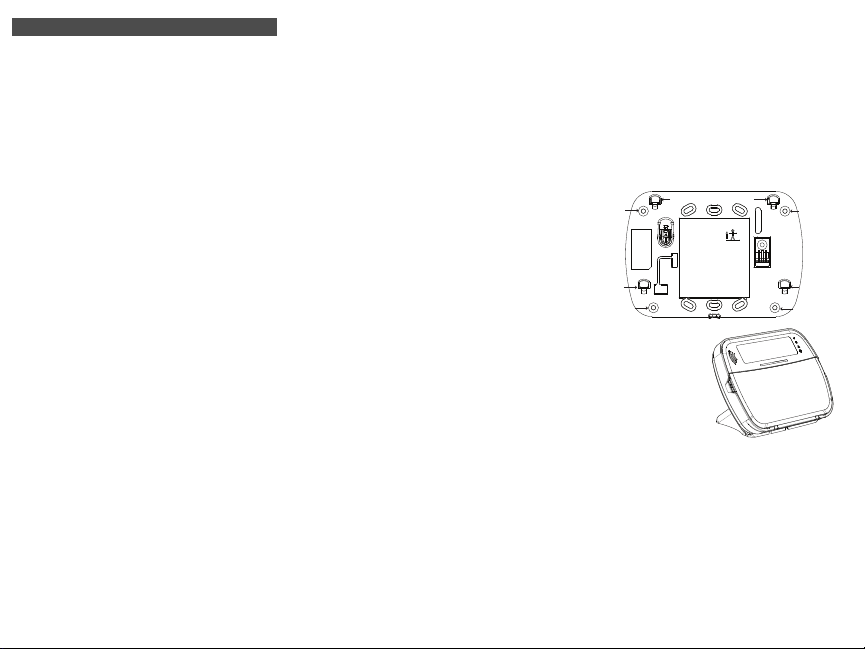
Wall Mounting Plate
1.Locate the screw holes (4) at each corner of the
mounting plate.
2.Use the four screws provided to affix the mounting plate to the wall; ensure the mounting tabs
are facing you (see following diagram). If the
keypad is to be mounted on drywall, use plastic
anchors.
3.Once the batteries are installed, align the four
mounting slots in the HS2LCDWF housing with
the four mounting tabs protruding from the
mounting plate.
4.Firmly but carefully snap the keypad down onto
the mounting plate.
Screw hole
Mounting tab
Screw hole
Desk Stand HS2LCDWFDMK
(Optional)
1.Insert the four rubber feet (found in
the hardware pack)
into the indentations
provided in the bottom of the desk
stand.
2.Place the desk stand on a secure, uncluttered surface.
3.Align the four mounting slots in the HS2LCDWF
housing with the four mounting tabs protruding
from the desk stand.
4.Slide the keypad into place. Firmly but carefully
snap the keypad down onto the desk stand.
5.To fasten the keypad securely onto the desk
stand, locate the hole in the center of the bottom
of the desk stand. Using the screws provided,
screw the keypad to the desk stand.
Mounting tab
Mounting tab
Screw hole
Mounting tab
Screw hole

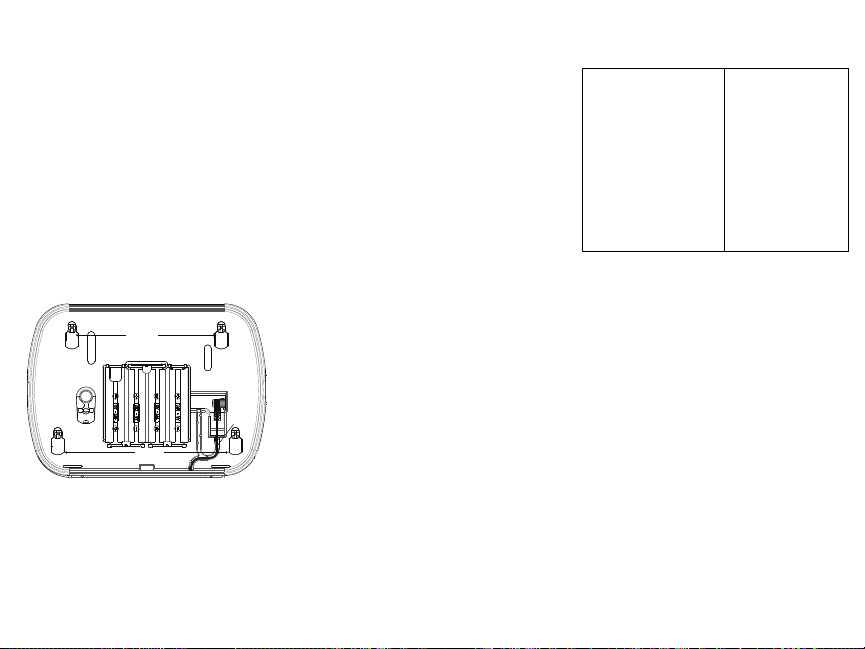
Apply Battery Power
1.If required, slide the keypad up and out from the
mounting plate/desk stand (removing the screws
first if required). The bay for the four AA batteries is open and visible at the back of the keypad.
2.Insert the batteries as directed on the back of the
keypad. Ensure the correct polarity is observed.
3.Replace the keypad on the mounting plate/desk
stand.
CAUTION: Do not mix old batteries with new ones.
Mounting
Holes
Plug
Wire
channel
Mounting
Holes
Apply AC Power
CAUTION: The socket-outlet in which the direct
plug-in adaptor is inserted must be close to the keypad, easily accessible, and have unobstructed access.
The plug of the adaptor serves as a means of disconnection from the supply mains.
1.Slide the keypad up and out from the mounting
plate/desk stand.
2.Locate the power adaptor jack at the back of the
keypad housing.
3.Place the adaptor plug in the housing indentation,
perpendicular to the keypad. Insert the adaptor
plug firmly into the jack.
4.Pivot the adaptor plug downwards so that it fits
flush with the housing. Guide the AC wire along
the channel provided in the keypad housing; the
wire will extend through the bottom of the housing.
5.Replace the keypad on the mounting plate/desk
stand (in the latter case, a further channel is provided in the bottom of the desk stand. Guide the
AC wire along this channel; the wire will extend
through an opening in the back of the stand).
6.Plug the adaptor into a wall outlet.
Only use the power adaptor (9.0VDC, @1.25A,
2.25W, limited power supply for models: HK-XX11U09N (UL) and HK-XX11-U09NC (ULC).
Program the Keypad
There are several programming options available for
the keypad (see the following table). Programming
the keypad is similar to programming the rest of the
system. The installer menu is a text driven flow. For
information on programming the rest of your security
system, refer to your system’s installation manual.
1.Press [*][8][Installer Code].
2.Use the [<][>] keys to navigate through the
menus or jump directly to a specific section by
entering the section number.
Language Programming
To enter language programming, enter [000]>[000].
Then enter the two-digit number that corresponds to
the language desired:
01 = English (default)
02 = Spanish
03 = Portuguese
04 = French
05 = Italian
06 = Dutch
07 = Polish
08 = Czech
09 = Finnish
10 = German
11 = Swedish
12 = Norwegian
13 = Danish
14 = Hebrew
15 = Greek
Enroll HSM2HOST
The HSM2HOST wireless transceiver or HS2LCDRF/HS2ICNRF keypad must be enrolled onto the
alarm panel before any wireless devices can be
enrolled. When the alarm system is powered up for
the first time, the first keypad or the HSM2HOST (if
using a wireless keypad as the first keypad) can be
enrolled. To do this:
1.Once the HSM2HOST is wired to the alarm panel
and power has been applied, power up a wireless
keypad.
2.Press any button on the keypad to enroll it on the
HSM2HOST. The HSM2HOST is then automatically enrolled on the alarm panel.
16 = Turkish
17 = FFU
18 = Croatian
19 = Hungarian
20 = Romanian
21 = Russian
22 = Bulgarian
23 = Latvian
24 = Lithuanian
25 = Ukrainian
26 = Slovakian
27 = Serbian
28 = Estonian
29 = Slovenian
Enroll Keypad
1. Press [*][8][Installer Code] and then [804][000].
2.When prompted, either activate the device to
enroll immediately or enter a device serial number. Do the latter to pre-enroll devices then enroll
them later at the customer site.
3.Use the [<][>] keys or enter the corresponding
number to select an option.
4.Scroll through the available selections and enter a
number or enter text as appropriate.
5.Press [*] to accept and move to the next option.
6.Once all options are configured, the system
prompts you to enroll the next device.
7.Repeat this process until all wireless devices are
enrolled.
NOTE: For UL/ULC Residential Fire applications,
HS2LCDWF9, HS2LCDWFP9, HS2LCDWFPV9
keypads must be set up for 200 seconds wireless
supervision, by enabling toggle option 4 (200s Fire
Supv), in section [804][810].
Delete Keypad
1. Press [*][8][Installer Code] and then [804][905].
2.Use the [<][>] keys to select the keypad or press
[#] to exit.
3.Press [*] to delete. The screen will read “Keypad
deleted”.
Program Labels
Use this section to assign a meaningful name (e.g.,
Front Door, Hallway, etc.) to each zone.
1.Press [*][8] [Installer code].
2.Press [*]
3.Scroll to the zone label to be programmed and
4.Scroll to the desired character’s location using the
5.Enter the number of the corresponding character
[1] - A, B, C, 1 [4] - J, K, L, 4 [7] - S, T, U, 7 [0] - Space
[2] - D, E, F, 2 [5] - M, N, O, 5 [8] - V, W, X, 8 [*] - Select
[3] - G, H, I, 3 [6] - P, Q, R, 6 [9] - Y, Z, 9,0 [#] - Escape
and use the [<][>] keys to scroll to Zone
Labels and press [*] again. The first zone is displayed. Alternatively, enter [000][001].
press [*] or enter the zone number (e.g., 001 for
zone label 1).
[<][>] keys.
group until the desired character is displayed (see
the following table).Example: Press the “2” key 3
times to enter the letter “F”. Press the “2” key 4
times to enter the number “2”.

6.To save the label, press [#], and the label is automatically saved. To delete a
character, use the [<][>] keys to move the cursor under the character, then
press [0]. If any key other than [<] or [>] is pressed before [0], the cursor
moves one space to the right and deletes that character.
ASCII Characters
Label Library
The Label Library is a database of words commonly used when programming
labels. Individual words can be combined as needed (e.g., Front + Door). Each
line of the display supports a maximum of 14 characters. If a word will not fit on
a line, scroll right until the cursor appears at the first character of the second line
then add the word
To program a custom label using the Label Library:
1.Press [*][8][Installer Code][000][001] (to program the label for zone 01).
2.Press [*] to open the menu.
3.Press [*] again to select the “Word Entry” option.
4.Enter the 3-digit number corresponding to a word (see Words Library) or
use the scroll keys [<][>] to view words in the library.
5.Press [*] to select the word.
6.To add another word, repeat the previous procedure from step 2.
7.To add a space, press the right scroll key [>].
8.To clear characters, select “Clear to End” or “Clear Display” from the
“Select Options” menu.
9.To save the label, press [#], and the label is automatically saved.
Broadcast LCD Labels
If more than one LCD keypad is present on the system, labels programmed at
one keypad will be broadcast to all other LCD keypads right after the change is
confirmed.
Voice Prompt/Voice Chime
Voice Prompt Control (for wireless keypads only)
Menu: [*][6][access code] > Voice Prompt
This function is used to change the volume level of keypad voice prompts, for
example, “User arming in progress.” The voice prompt speaks the zone labels
programmed for zone openings/closings. Use the scroll keys [<][>] to increase
or decrease the volume from levels 0-10. Selecting 00 turns off keypad voice
prompts.
Voice Chime Control
Menu: [*][6][access code] > Chime Control
This function is used to change the keypad voice chime volume level. Use the
scroll keys [<][>] to increase or decrease the volume from levels 0-10. Selecting
00 turns off voice chime.
.
Change Brightness/Contrast/Buzzer/
LCD Keypads
1.Press [*][6][Master Code].
2.Use the [<][>] keys to scroll to either Bright Control, Contrast Control,
Buzzer Control.
3.Press [*] to select the setting you want to adjust.
4. a) Brightness/LED Bar Control: There are 15 backlighting levels. Use the
[<][>] keys to scroll to the desired level. Changing this level adjusts the
LED bar accordingly.
b) Contrast Control: There are 15 different display contrast levels. Use the
[<][>] keys to scroll to the desired contrast level.
c) Buzzer Control: There are 15 different buzzer control levels. Use the [<][>]
keys to scroll to the desired buzzer level.
Keypad LED Symbols
Symbol Description
Ready Light (Green) If Ready light is ON, the system is ready to arm.
Armed Light (Red)
System Trouble (Yel-
low)
AC (Green) ON - Indicates that AC is present at the keypad.
Proximity Tags (HS2LCDWFP, HS2LCDWFPV only)
The proximity tag can be used to perform any keypad function that would normally require a user access code. The tag is to be presented to the center left face
of the keypad. While the keypad is running off AC, the transceiver is always on
to detect any prox tag approaching. While the keypad is running on battery and
in sleep mode, the user can press any key to wake the keypad, then present the
prox tag.
Enroll Proximity Tags
Enrolling a tag on one keypad will enroll it automatically to all HS2LCDWFP
or HS2LCDWFPV keypads enrolled on the system. Master code (code 1) cannot have a prox. tag assigned to it.
1.Press [*][5][Master Code].
2. Use the [<][>] keys to scroll to the applicable user and press [*].
3. Use the [<][>] keys to scroll to Prox Tag and press [*]. The screen displays:
“Present Tag”.
4.Pass the enrolled tag near the tag reader on the keypad. A prox tag can only
be assigned to one user at a time.
5.If enrollment is successful, acknowledgment beeps will sound and the keypad LCD will read ‘Tag Enrolled Successfully’. If enrollment is unsuccessful, an error tone will sound and the keypad will read ‘Invalid Tag Not
Enrolled’. If the tag has been enrolled previously, an error tone will sound
and the keypad will read ‘Duplicate Tag Not Enrolled’.
If Armed light is ON/Flashing, the system has
been armed successfully.
ON - Indicates that a system trouble is active.
Flashing - Keypad low battery.

Delete Proximity Tags
Delete the prox tags from the system when they are lost or no longer needed.
1.Press [*][5][Master Code].
2.The keypad displays the user number and includes the letter ‘T’ if a prox tag
is programmed.
3.Use the [<][>] keys to locate the desired user and press [*]. Scroll to Prox
Tag and press [*].
4.The keypad reads ‘Press [*] To Delete Tag’. After pressing [*], the message
‘Tag Deleted Successfully’ appears.
Keypad Function Key Programming 2
To program a function key:
1.Press [*][8][Installer Code].
2.Enter [861] for keypad programming. Section [860] is read-only and shows
the slot number of the keypad being accessed.
3.Enter [001]-[005] for function keys 1-5.
4.Enter a 2-digit number to assign a function key operation - [00]-[68]. See
the following tables.
5.Continue from step 3 until all function keys are programmed.
6.Press [#] twice to exit Installer Programming.
[001]-[005] Function Key Assignment
Function
Section
Key
[001] 1 00 - 68 03 Stay Arm I_______I_______I
[002] 2 00 - 68 04 Away Arm I_______I_______I
[003] 3 00 - 68 06
[004] 4 00 - 68 22
[005] 5 00 - 68 16
Keypad Function Keys
Please see your system installation manual for more details on the function key
options.
[00]
- Null [17] - Arm Interior [39] -Trouble Display
[02]
- Instant Stay Arm [21] - Command Output 1 [40] - Alarm Memory
[03]
- Stay Arm [22] - Command Output 2 [61] - Partition Select 1
[04]
- Away Arm [23] - Command Output 3 [62] - Partition Select 2
[05]
- [*][9]
[06]
[07]
[09]
No-Entry Arm
- Chime ON/OFF [29] - Bypass Group Recall [64] - Partition Select 4
- System Test [31] - Local PGM Activate [65] - Partition Select 5
- Night Arm [32] - Bypass Mode [66] - Partition Select 6
Valid
Button
Default Function
Range
Chime ON/
OFF
Command
Output 2
Quick
Exit
[24] - Command Output 4 [63] - Partition Select 3
I_______I_______I
I_______I_______I
I_______I_______I
[12]
- Global Stay Arm [33] - Bypass Recall [67] - Partition Select 7
[13]
- Global Away Arm [34] - User Programming [68] - Partition Select 8
[14]
- Global Disarming [35] - User Functions
[16] - Quick Exit [37] -Time and Date Program
Keypad Programming
Press [*][8][Installer Code]
[860] Keypad Slot Number
This is not for programming; the two-digit slot number is displayed for informational purposes only.
[861]-[876] Keypad Programming Sections
Sections [861]-[876] apply to keypad slot numbers 1-16 accordingly. After
selecting the appropriate keypad section number, the following programming
options are available:
[000] Address of Partition
On selecting [000], a 2-digit entry is required to assign the keypad to a partition.
Entering 00 assigns the keypad as global. Valid entries are 00-08. The default is
01.
[001]-[005] Function Key 1- 5 Assignment
[011] Keypad Input/Output Programming
Zone or PGM
Number
Default
00
I_____I_____I_____I
[012] Local PGM Output Pulse Activation Time
Minutes (00-99)
I_____I_____I
Seconds (00-99)
I_____I_____I
[021] First Keypad Options
Default Opt. ON OFF
ON I______I 1
ON I______I 2
ON I______I 3
ON I______I 4
OFF
I______I
OFF
I______I
OFF
I______I
OFF
I______I
Fire Key Enabled Fire Key Disabled
Medical Key Enabled Medical Key Disabled
Panic Key Enabled Panic Key Disabled
Display Access Code
When Programming
5 For Future Use For Future Use
6 For Future Use For Future Use
7 For Future Use For Future Use
8 For Future Use For Future Use
Display X’s When Programming Access
Codes

[022] Second Keypad Options
Default Opt. ON OFF
ON I______I 1
OFF I______I 2
ON I______I 3
OFF I______I 4
OFF I______I 5
ON I______I 6
ON I______I 7
OFF I______I 8
[023] Third Keypad Options
Default Opt. ON OFF
OFF I______I
ON I______I
OFF I______I
NOTE: Programming options indicated in GREY are required for systems com-
pliant with EN50131-1 and EN50131-3 standards. Section [023]: 1=OFF
Local Clock Display ON
Local Clock Displays 24-
hr Time
Auto Alarm Scroll ON
For Future Use For Future Use
Power LED Enabled Power LED Disabled
Power LED Indicates AC
Present ON
Alarms Displayed While
Armed
Auto-Scroll Open Zones ONAuto-Scroll Open
Armed LED On in
1
Sleep Mode
Keypad Status Shows
2
Stay Arm
Temperature Display
7
Enabled
Local Clock Display
OFF
Local Clock Displays
AM/PM
Auto Alarm Scroll
OFF
Power LED Indicates
AC Present OFF
Alarms Not Displayed
While Armed
Zones OFF
Armed LED Off in Sleep
Mode
Keypad Status Shows Stay/
Away Arm
Temperature Display Disabled
[030] LCD Message
I_____I_____I_____I_____I_____I_____I_____I_____I_____I_____I_____I_____I_____I_____I_____I_____|
I_____I_____I_____I_____I_____I_____I_____I_____I_____I_____I_____I_____I_____I_____I_____I_____|
[031] Downloaded LCD Message Duration
Default: 000 I_____I_____I_____I (Valid entries are 000-255), 000=Unlimited Message Display. This number represents the number of times the downloaded
message must be cleared before it is permanently removed.
Press any key to delete message.
[041] Indoor Temperature Zone Assignment
Default: 000
[042] Outdoor Temperature Zone Assignment
Default: 000
I______I______I______I
I______I______I______I
(Valid entries are 000-128)
(Valid entries are 000-128)
[101]-[228] Door Chime for Zones 1-128
The keypad can be programmed to make up to four different chime
sounds for individual zones. (e.g., for Zone 1, enter Section [101], for
Zone 2 enter Section [102]).
I___I___I
Default: 01
Option
01 6 beeps
02 Bing-Bing tone
03 Ding-Dong tone
04 Alarm tone (4 second duration)
05 Zone name
[991] Reset Keypad Programming to Factory Defaults
1.Press [*][8][Installer Code].
2.Enter [991].
3.Use the [<][>] keys to scroll to the applicable keypad.
4.Press [*] to select the keypad.
5.Re-enter [Installer Code].
6.Press [*] to reset the selected keypad to factory defaults.

Word Library
Item # Text Item # Text Item # Text Item # Text Item # Text Item # Text
001 Aborted 042 Control 083 Garage 124 Motion 165 Shock 206 D
002 AC 043 Date 084 Gas 125 No 166 Shop 207 E
003 Access 044 Daughter’s 085 Glass 126 North 167 Side 208 F
004 Active 045 Degrees 086 Goodbye 127 Not 168 Siren 209 G
005 Activity 046 Delay 087 Gym 128 Now 169 Sliding 210 H
006 Alarm 047 Den 088 Hallway 129 Number 170 Smoke 211 I
007 All 048 Desk 089 Heat 130 Off 171 Son’s 212 J
008 AM 049 Detector 090 Hello 131 Office 172 Sound 213 K
009 Area 050 Dining 091 Help 132 OK 173 South 214 L
010 Arm 051 Disarmed 092 High 133 On 174 Special 215 M
011 Armed 052 Door 093 Home 134 Open 175 Stairs 216 N
012 Arming 053 Down 094 House 135 Opening 176 Stay 217 O
013 Attic 054 Download 095 In 136 Panic 177 Sun 218 P
014 Auxiliary 055 Downstairs 096 Install 137 Partition 178 Supervisory 219 Q
015 Away 056 Drawer 097 Interior 138 Patio 179 System 220 R
016 Baby 057 Driveway 098 Intrusion 139 Pet 180 Tamper 221 S
017 Back 058 Duct 099 Invalid 140 Phone 181 Temperature 222 T
018 Bar 059 Duress 100 Is 141 Please 182 Test 223 U
019 Basement 060 East 101 Key 142 PM 183 Time 224 V
020 Bathroom 061 Energy 102 Kids 143 Police 184 To 225 W
021 Battery 062 Enter 103 Kitchen 144 Pool 185 Touchpad 226 X
022 Bedroom 063 Entry 104 Latchkey 145 Porch 186 Trouble 227 Y
023 Bonus 064 Error 105 Laundry 146 Power 187 Unbypass 228 Z
024 Bottom 065 Exercise 106 Left 147 Press 188 Unit 229 Space
025 Breezeway 066 Exit 107 Level 148 Program 189 Up 230 ,
026 Building 067 Exterior 108 Library 149 Progress 190 West 231 027 Bus 068 Factory 109 Light 150 Quiet 191 Window 232 _ (Underscore)
028 Bypass 069 Failure 110 Lights 151 Rear 192 Zone 233 *
029 Bypassed 070 Family 111 Living 152 Receiver 193 0 234 #
030 Cabinet 071 Father’s 112 Load 153 Report 194 1 235 :
031 Canceled 072 Feature 113 Loading 154 RF 195 2 236 /
032 Car 073 Fence 114 Low 155 Right 196 3 237 ?
033 Carbon 074 Fire 115 Lower 156 Room 197 4
034 Central 075 First 116 Main 157 Safe 198 5
035 Chime 076 Floor 117 Master 158 Saver 199 6
036 Closed 077 Force 118 Mat 159 Schedule 200 7
037 Closet 078 Foyer 119 Medical 160 Screen 201 8
038 Closing 079 Freeze 120 Memory 161 Second 202 9
039 Code 080 Front 121 Menu 162 Sensor 203 A
040 Communicator 081 Furnace 122 Monoxide 163 Service 204 B
041 Computer 082 Gallery 123 Mother’s 164 Shed 205 C

Limited Warranty
Digital Security Controls (DSC) warrants that for a period of 12 months from the date of purchase, the product shall be free of defects in materials and workmanship under normal use and
that in fulfillment of any breach of such warranty, DSC shall, at its option, repair or replace the
defective equipment upon return of the equipment to its repair depot. This warranty applies only
to defects in parts and workmanship and not to damage incurred in shipping or handling, or
damage due to causes beyond the control of DSC such as lightning, excessive voltage,
mechanical shock, water damage, or damage arising out of abuse, alteration or improper application of the equipment. The foregoing warranty shall apply only to the original buyer, and is
and shall be in lieu of any and all other warranties, whether expressed or implied and of all other
obligations or liabilities on the part of DSC. DSC neither assumes responsibility for, nor authorizes any other person purporting to act on its behalf to modify or to change this warranty, nor to
assume for it any other warranty or liability concerning this product. In no event shall DSC be
liable for any direct, indirect or consequential damages, loss of anticipated profits, loss of time
or any other losses incurred by the buyer in connection with the purchase, installation or operation or failure of this product. WARNING: DSC recommends that the entire system be com-
pletely tested on a regular basis. However, despite frequent testing, and due to, but not limited
to, criminal tampering or electrical disruption, it is possible for this product to fail to perform as
expected. Important Information: Changes or modifications not expressly approved by DSC
could void the user’s authority to operate this equipment.
EN50131-1 Grade 2, Class 2, EN50131-6 Type B
Important Information
the user’s authority to operate this equipment.
IMPORTANT - READ CAREFULLY: DSC Software purchased with or without Products and
Components is copyrighted and is purchased under the following license terms:
• This End-User License Agreement (“EULA”) is a legal agreement between
company, individual or entity who acquired the Software and any related Hardware) and
Digital Security Controls, a division of Tyco Safety Products Canada Ltd.
manufacturer of the integrated security systems and the developer of the software and any
related products or components (“HARDWARE”) which You acquired.
• If the DSC software product (“SOFTWARE PRODUCT” or “SOFTWARE”) is intended to
be accompanied by HARDWARE, and is NOT accompanied by new HARDWARE, You may
not use, copy or install the SOFTWARE PRODUCT. The SOFTWARE PRODUCT includes
computer software, and may include associated media, printed materials, and “online” or
electronic documentation.
• Any software provided along with the SOFTWARE PRODUCT that is associated with a
separate end-user license agreement is licensed to You under the terms of that license
agreement.
• By installing, copying, downloading, storing, accessing or otherwise using the SOFTWARE PRODUCT, You agree unconditionally to be bound by the terms of this EULA, even if
this EULA is deemed to be a modification of any previous arrangement or contract. If You do
not agree to the terms of this EULA, DSC is unwilling to license the SOFTWARE PRODUCT
to You, and You have no right to use it.
SOFTWARE PRODUCT LICENSE
The SOFTWARE PRODUCT is protected by copyright laws and international
copyright treaties, as well as other intellectual property laws and treaties. The
SOFTWARE PRODUCT is licensed, not sold.
1. GRANT OF LICENSE This EULA grants You the following rights:
(a) Software Installation and Use - For each license You acquire, You may have only one
copy of the SOFTWARE PRODUCT installed.
(b) Storage/Network Use - The SOFTWARE PRODUCT may not be installed, accessed,
displayed, run, shared or used concurrently on or from different computers, including a workstation,
terminal or other digital electronic device (“Device”). In other words, if You have several workstations,
You will have to acquire a license for each workstation where the SOFTWARE will be used.
(c) Backup Copy - You may make back-up copies of the SOFTWARE PRODUCT, but You may
only have one copy per license installed at any given time. You may use the back-up copy solely for
archival purposes. Except as expressly provided in this EULA, You may not otherwise make copies of
the SOFTWARE PRODUCT, including the printed materials accompanying the SOFTWARE.
2. DESCRIPTION OF OTHER RIGHTS AND LIMITATIONS
(a) Limitations on Reverse Engineering, Decompilation and Disassembly - You may not
reverse engineer, decompile, or disassemble the SOFTWARE PRODUCT, except and only to the extent
that such activity is expressly permitted by applicable law notwithstanding this limitation. You may not
make any changes or modifications to the Software, without the written permission of an officer of
DSC. You may not remove any proprietary notices, marks or labels from the Software Product. You
shall institute reasonable measures to ensure compliance with the terms and conditions of this EULA.
(b)
Separation of Components
product. Its component parts may not be separated for use on more than one HARDWARE
unit.
(c)
Single INTEGRATED PRODUCT
then the SOFTWARE PRODUCT is licensed with the HARDWARE as a single integrated
product. In this case, the SOFTWARE PRODUCT may only be used with the HARDWARE as
set forth in this EULA.
: Changes/modifications not expressly approved by DSC could void
- The SOFTWARE PRODUCT is licensed as a single
- If You acquired this SOFTWARE with HARDWARE,
(d)
make it available to others or post it on a server or web site.
(e)
as part of a permanent sale or transfer of the HARDWARE, provided You retain no copies,
You transfer all of the SOFTWARE PRODUCT (including all component parts, the media and
printed materials, any upgrades and this EULA), and provided the recipient agrees to the
terms of this EULA. If the SOFTWARE PRODUCT is an upgrade, any transfer must also
include all prior versions of the SOFTWARE PRODUCT.
(f)
You fail to comply with the terms and conditions of this EULA. In such event, You must
destroy all copies of the SOFTWARE PRODUCT and all of its component parts.
g)
trademarks or service marks of DSC or its suppliers.
3. COPYRIGHT
PRODUCT (including but not limited to any images, photographs, and text incorporated into
the SOFTWARE PRODUCT), the accompanying printed materials, and any copies of the
SOFTWARE PRODUCT, are owned by DSC or its suppliers. You may not copy the printed
materials accompanying the SOFTWARE PRODUCT. All title and intellectual property rights
in and to the content which may be accessed through use of the SOFTWARE PRODUCT are
the property of the respective content owner and may be protected by applicable copyright
or other intellectual property laws and treaties. This EULA grants You no rights to use such
content. All rights not expressly granted under this EULA are reserved by DSC and its
suppliers.
4. EXPORT RESTRICTIONS
PRODUCT to any country, person, or entity subject to Canadian export restrictions.
5. CHOICE OF LAW
Province of Ontario, Canada.
You
(the
6. ARBITRATION
by final and binding arbitration in accordance with the Arbitration Act, and the parties agree to
(“DSC”), the
be bound by the arbitrator’s decision. The place of arbitration shall be Toronto, Canada, and
the language of the arbitration shall be English.
7. LIMITED WARRANTY
(a) NO WARRANTY
DOES NOT WARRANT THAT THE SOFTWARE WILL MEET YOUR REQUIREMENTS OR THAT
OPERATION OF THE SOFTWARE WILL BE UNINTERRUPTED OR ERROR-FREE.
(b) CHANGES IN OPERATING ENVIRONMENT -
caused by changes in the operating characteristics of the HARDWARE, or for problems in
the interaction of the SOFTWARE PRODUCT with non-DSC-SOFTWARE or HARDWARE
PRODUCTS.
(c) LIMITATION OF LIABILITY; WARRANTY REFLECTS ALLOCATION OF RISK - IN ANY
EVENT, IF ANY STATUTE IMPLIES WARRANTIES OR CONDITIONS NOT STATED IN THIS LICENSE
AGREEMENT, DSC’S ENTIRE LIABILITY UNDER ANY PROVISION OF THIS LICENSE AGREEMENT
SHALL BE LIMITED TO THE GREATER OF THE AMOUNT ACTUALLY PAID BY YOU TO LICENSE THE
SOFTWARE PRODUCT AND FIVE CANADIAN DOLLARS (CAD$5.00). BECAUSE SOME
JURISDICTIONS DO NOT ALLOW THE EXCLUSION OR LIMITATION OF LIABILITY FOR
CONSEQUENTIAL OR INCIDENTAL DAMAGES, THE ABOVE LIMITATION MAY NOT APPLY TO YOU.
(d) DISCLAIMER OF WARRANTIES - THIS WARRANTY CONTAINS THE ENTIRE WARRANTY AND
SHALL BE IN LIEU OF ANY AND ALL OTHER WARRANTIES, WHETHER EXPRESSED OR IMPLIED
(INCLUDING ALL IMPLIED WARRANTIES OF MERCHANTABILITY OR FITNESS FOR A PARTICULAR
PURPOSE) AND OF ALL OTHER OBLIGATIONS OR LIABILITIES ON THE PART OF DSC. DSC MAKES
NO OTHER WARRANTIES. DSC NEITHER ASSUMES NOR AUTHORIZES ANY OTHER PERSON
PURPORTING TO ACT ON ITS BEHALF TO MODIFY OR TO CHANGE THIS WARRANTY, NOR TO
ASSUME FOR IT ANY OTHER WARRANTY OR LIABILITY CONCERNING THIS SOFTWARE PRODUCT.
(e) EXCLUSIVE REMEDY AND LIMITATION OF WARRANTY - UNDER NO CIRCUMSTANCES
SHALL DSC BE LIABLE FOR ANY SPECIAL, INCIDENTAL, CONSEQUENTIAL OR INDIRECT DAMAGES
BASED UPON BREACH OF WARRANTY, BREACH OF CONTRACT, NEGLIGENCE, STRICT LIABILITY,
OR ANY OTHER LEGAL THEORY. SUCH DAMAGES INCLUDE, BUT ARE NOT LIMITED TO, LOSS OF
PROFITS, LOSS OF THE SOFTWARE PRODUCT OR ANY ASSOCIATED EQUIPMENT, COST OF
CAPITAL, COST OF SUBSTITUTE OR REPLACEMENT EQUIPMENT, FACILITIES OR SERVICES, DOWN
TIME, PURCHASERS TIME, THE CLAIMS OF THIRD PARTIES, INCLUDING CUSTOMERS, AND INJURY
TO PROPERTY.
completely tested on a regular basis. However, despite frequent testing, and
due to, but not limited to, criminal tampering or electrical disruption, it is
possible for this SOFTWARE PRODUCT to fail to perform as expected.
FCC Compliance Statement
Caution: Changes or modifications not expressly approved by Digital Security Controls could
void your authority to use this equipment.
This equipment generates and uses radio frequency energy and if not installed and used
properly, in strict accordance with the manufacturer’s instructions, may cause interference to
radio and television reception.
It has been type tested and found to comply with the limits for Class B device in accordance with
the specifications in Subpart “B” of Part 15 of FCC Rules, which are designed to provide
Rental
- You may not rent, lease or lend the SOFTWARE PRODUCT. You may not
Software Product Transfer
Termination
Trademarks
- You may transfer all of Your rights under this EULA only
- Without prejudice to any other rights, DSC may terminate this EULA if
- This EULA does not grant You any rights in connection with any
- All title and intellectual property rights in and to the SOFTWARE
- You agree that You will not export or re-export the SOFTWARE
- This Software License Agreement is governed by the laws of the
- All disputes arising in connection with this Agreement shall be determined
- DSC PROVIDES THE SOFTWARE “AS IS” WITHOUT WARRANTY. DSC
DSC shall not be responsible for problems
WARNING: DSC recommends that the entire system be
reasonable protection against such interference in any residential installation. However, there is
no guarantee that interference will not occur in a particular installation. If this equipment does
cause interference to television or radio reception, which can be determined by turning the
equipment off and on, the user is encouraged to try to correct the interference by one or more of
the following measures: (i) Re-orient the receiving antenna; (ii) increase the separation between
the equipment and receiver; (iii) connect the equipment into an outlet on a circuit different from
that to which the receiver is connected. If necessary, the user should consult the dealer or an
experienced radio/television technician for additional suggestions. The user may find the
following booklet prepared by the FCC helpful: “How to Identify and Resolve Radio/Television
Interference Problems”. This booklet is available from the U.S. Government Printing Office,
Washington, D.C. 20402, Stock # 004-000-00345-4.
This Class B digital apparatus complies with Canadian ICES-003.
Cet appareil numérique de la classe B est conforme à la norme NMB-003 du Canada. IC:160AHS2LCDWF The term IC before the radio certification number signifies that the Industry Canada
technical specifications were met.
The trademarks, logos, and service marks displayed on this document are registered in the
United States [or other countries]. Any misuse of the trademarks is strictly prohibited and Tyco
International Ltd. will aggressively enforce its intellectual property rights to the fullest extent of
the law, including pursuit of criminal prosecution wherever necessary. All trademarks not owned
by Tyco International Ltd. are the property of their respective owners, and are used with
permission or allowed under applicable laws. Product offerings and specifications are subject to
change without notice. Actual products may vary from photos. Not all products include all
features. Availability varies by region; contact your sales representative.
+HUHE\ '6& GHFODUHV WKDW WKLV GHYLFH LV LQ FRPSOLDQFH ZLWK WKH HVVHQWLDO
UHTXLUHPHQWVDQGRWKHUUHOHYDQWSURYLVLRQVRI'LUHFWLYH(&
7KH FRPSOHWH 577( 'HFODUDWLRQ RI &RQIRUPLW\ FDQ EH IRXQG DW
KWWSZZZGVFFRPOLVWLQJVBLQGH[DVS[
&=( '6& MDNR Y¿UREFH SURKODģXMH ŀH WHQWR Y¿UREHN MH Y VRXODGX VH YģHPL
UHOHYDQWQ¯PLSRŀDGDYN\VPÝUQLFH(&
'$1'6&HUNO¨UHUKHUYHGDWGHQQHNRPSRQHQWHQRYHUKROGHUDOOHYLNWLJHNUDY VDPW
DQGUHEHVWHPPHOVHUJLWWLGLUHNWLY(&
'87+LHUELM YHUNODDUW'6& GDWGLW WRHVWHOLQ RYHUHHQVWHPPLQJLV PHWGH HLVHQHQ
EHSDOLQJHQYDQULFKWOLMQ(&
),1'6&YDNXXWWDDODLWWHHQW¦\WW¦Y¦QGLUHNWLLYLQ(&ROHQQDLVHWYDDWLPXNVHW
)5(3DU ODSU«VHQWH '6&G«FODUH TXH FHGLVSRVLWLI HVWFRQIRUPH DX[H[LJHQFHV
HVVHQWLHOOHVHWDXWUHVVWLSXODWLRQVSHUWLQHQWHVGHOD'LUHFWLYH(&
*(5+LHUGXUFKHUNO¦UW'6&GD¡GLHVHV*HU¦WGHQHUIRUGHUOLFKHQ%HGLQJXQJHQ XQG
9RUUDXVHW]XQJHQGHU5LFKWOLQLH(&HQWVSULFKW
*5(˂˜˞˱ˬ˲ ˭˞ˮ˹˪˱ˬ˯ˤ'6& ˡˤ˨˻˪ˢ˦˹˱˦˞˲˱˛ ˤ˰˲˰˧ˢ˲˛ˢ˜˪˞˦ ˰˺˩˳˶˪ˤ˩ˢ˱˦˯
ˬ˲˰˦˻ˡˤ˯˞˭˞˦˱˛˰ˢ˦˯˧˞˦˩ˢ˹˨ˢ˯˱˦˯˙˨˨ˢ˯˰˴ˢ˱˦˧˚˯˞˪˞˳ˬˮ˚˯˱ˤ˯ˍˡˤˠ˜˞˯(&
,7$ &RQOD SUHVHQWH OD 'LJLWDO 6HFXULW\ &RQWUROVGLFKLDUD FKH TXHVWR SURGRWWR ª
FRQIRUPH DL UHTXLVLWLHVVHQ]LDOL HG DOWUH GLVSRVL]LRQL ULOHYDQWL UHODWLYH DOOD 'LUHWWLYD
&(
125'6&HUNO¨UHUDWGHQQH HQKHWHQHULVDPVYDUPHGGH JUXQQOHJJHQGHNUDYRJ
ºYULJHUHOHYDQWHNUDYLGLUHNWLY()
32/'6&RĝZLDGF]DľHXU]ÇG]HQLHMHVWZ]JRGQRĝFL]]DVDGQLF]\PLZ\PDJDQLDPL
RUD]SR]RVWDĄ\PLVWRVRZQ\PLSRVWDQRZLHQLDPL'\UHNW\Z\:(
3253RUHVWH PHLRD'6&GHFODUD TXHHVWHHTXLSDPHQWRHVW£ HPFRQIRUPLGDGH
FRP RV UHTXLVLWRV HVVHQFLDLV H RXWUDV GHWHUPLQD©·HV UHOHYDQWHV GD 'LUHFWLYD
(&
63$3RU ODSUHVHQWH'6& GHFODUDTXH HVWHHTXLSR HVW£HQFRQIRUPLGDG FRQORV
UHTXLVLWRVHVHQFLDOHV\RWURVUHTXLVLWRVUHOHYDQWHVGHOD'LUHFWLYD(&
6:('6&EHNU¦IWDU K¦UPHGDWW GHQQDDSSDUDWXSSI\OOHU GHY¦VHQWOLJDNUDYHQ RFK
DQGUDUHOHYDQWDEHVW¦PPHOVHUL'LUHNWLYHW(&
This installation sheet applies to the following models:
HS2LCDWF, HS2LCDWFP, and HS2LCDWFPV.
CAUTION: Do not dispose of the waste battery as
unsorted municipal waste. Consult your local rules and/or
laws regarding recycling of this battery.
© 2014 Tyco International Ltd. and its Respective Companies. All Rights Reserved. Toronto, Canada •
www.dsc.com • Tech Support: 1-800-387-3630 (Canada,
US), 905-760-3000

Instructions d'installation
Ces instructions doivent être utilisées conjointement
au manuel d'installation de la centrale avec laquelle
il est prévu d'utiliser cet équipement. Les
instructions de fonctionnement doivent rester
disponibles pour l'utilisateur
Le pavé numérique sans fil HS2LCDWF est
compatible avec les émetteurs-récepteurs sans fil
HSM2HOST et les pavés numériques HS2LCDRF.
Caractéristiques techniques
• Plage de Température : de -10°C à +55°C (de
14°F à 131°F) UL/ULC: de 0°C à +49°C (de
32°F à 120°F)
• Humidité (MAX) : 93% du taux d'humidité
relative, sans condensation
• Degré de protection du boîtier plastique : IP30,
IK04
• Tension de sortie de l'adaptateur d'alimentation :
9,0 VCC à 1,25 A. Modèle : États Unis/Amérique
Latine : HK-XX11-U09N (UL), Canada : HKXX11-U09NC (ULC), Union Européenne : HKXX11-U09EU, Royaume-Uni : HK-XX11U09NGB, Australie/Nouvelle-Zélande, Chine :
HK-XX11-U09NAU à alimentation limitée,
acceptable pour l'autorité compétente
REMARQUE: Des restrictions sont appliquées
pour les installations UL.
REMARQUE: Ce produit ne doit pas être connecté
à une prise électrique commandée par un
interrupteur.
• Batterie. 4 batteries de type AA, 1,5V, Energizer
alcaline, grand public (E91)
• Signal de batterie faible : 4,5V
• Courant absorbé HS2LCDWF : 30mA(min)/
100mA(max)
• Contact anti-sabotage à montage mural (connecté
pour les installations commerciales UL
• 5 touches de fonctions programmables
• Voyant lumineux « Prêt » (vert), « Armé »
(rouge), Problème/Interférence RF (rouge/jaune),
Alimentation secteur (vert)
• Fréquence : 433 MHz (Brésil, Chine, Australie
(CE), Nouvelle-Zélande (NA), Afrique du sud
(ICASA), MEA, Inde (WPC)
• Fréquence : 868 MHz (EN + Local, MEA (CE))
• Fréquence : 912 - 919 MHz (NA/LATAM,
Argentine)
REMARQUE: Pour les installations commerciales
UL, les contacts anti-sabotage sont activés.
Contenu de l'emballage
Le coffret du pavé numérique HS2LCDWF est
disponible en trois configurations.
Le pavé numérique dispose d'une technologie
brevetée pour la balise de proximité (Prox).
HS2LCDWF : montage
mural
• 1 pavé numérique
HS2LCDWF
• 1 support mural
HS2LCDWF
• 1 manuel d'installation • 1 manuel d'installation
• 1 autocollant pour
porte intérieure
• 4 batteries de type AA • 4 batteries de type AA
• 1 ensemble matériel • 1 ensemble matériel
HS2LCDWFPV : balise
de proximité avec
annonceur vocal
• 1 support mural
HS2LCDWFBRK
• 1 manuel d'installation
• 1 autocollant pour
porte intérieure
• 1 adaptateur
d'alimentation
• 4 batteries de type AA
• 1 ensembles matériels
• 1 balise de proximité
HS2LCDWFP : balise
de proximité
• 1 pavé numérique
HS2LCDWF
• 1 support mural
HS2LCDWF
• 1 autocollant pour porte
intérieure
• 1 balise de proximité
Fixation
Installez le pavé numérique où il est accessible aux
points désignés d'entrée et de sortie. Une fois un
endroit sec et sûr choisi, réalisez les opérations
suivantes pour installer le pavé numérique.
Plaque de fixation murale
1.Localisez les trous de vis (4) à chaque coin de la
plaque de fixation.
2.Utilisez les quatre vis fournies pour serrer la
plaque de fixation au mur, vérifiez que les
onglets de fixation font face vers vous (voir
schéma ci-dessous). Si le pavé numérique doit
être installé sur une cloison sèche, utilisez des
chevilles en plastique (non fournies).
3.Une fois l'alimentation secteur et les batteries
installées, alignez les quatre fentes de montage
du boîtier HS2LCDWF avec les quatre onglets
de fixation en saillie de la plaque de fixation.
4.Montez fermement mais avec soin le pavé
numérique sur la plaque de fixation.
Onglet de fixation
Trou de vis
Onglet de
fixation
Trou de vis
Support de
bureau :
HS2LCDWFDMK
1.Insérez les quatre
pieds en caoutchouc
(voir ensemble
matériel) dans les
renfoncements
prévus au bas du
support de bureau.
2.Placez le support de
bureau sur une surface stable et dégagée.
Onglet de fixation
Trou de vis
Onglet de
fixation
Trou de vis
3.Alignez les quatre fentes de montage du boîtier
HS2LCDWF avec les quatre onglets de fixation
en saillie du support de bureau.
4.Faites glisser le pavé numérique en place. Montez
fermement mais avec soin le pavé numérique sur
le support de bureau.
5.Pour fixer en toute sécurité le pavé numérique sur
le support de bureau, localisez le trou en bas et au
milieu de celui-ci. À l'aide des vis fournies, vissez
le pavé numérique au support de bureau.
Alimentation par batterie
1.Si nécessaire, faites glisser le pavé numérique
vers le haut et hors de la plaque de fixation ou le
support de bureau (retirez d'abord les vis si
nécessaire). Le logement des quatre batteries AA
est ouvert et visible à l'arrière du pavé numérique.
2.Insérez les batteries dans le sens indiqué sur
l'arrière du pavé numérique. Veillez à respecter
les polarités.
3.Remontez le pavé numérique sur la plaque de
fixation ou le support de bureau.
ATTENTION: Ne mélangez pas les batteries usées et
les nouvelles.
Trous de
fixation
Fiche
Passage
du câble
Trous de
fixation
Alimentation par secteur
ATTENTION: La prise électrique dans laquelle la
prise directe de l'adaptateur est insérée doit être à
proximité du pavé numérique, facilement accessible et
dégagée de tout obstacle. La fiche de l'adaptateur sert
de moyen de déconnexion de l'alimentation secteur.
1.Si nécessaire, faites glisser le pavé numérique
vers le haut et hors de la plaque de fixation ou du
support de bureau.
2.Localisez la prise de l'adaptateur d'alimentation à
l'arrière du boîtier du pavé numérique.
3.Placez la prise de l'adaptateur dans le
renfoncement du boîtier, de façon perpendiculaire
au pavé numérique. Insérez fermement la fiche de
l'adaptateur dans la prise.
4.Faites pivoter la fiche de l'adaptateur vers le bas
de façon qu'il soit à ras du boîtier. Guidez le
cordon secteur le long du passage intégré dans le
boîtier du pavé numérique.
5.Remontez le pavé numérique sur la plaque de
fixation ou le support de bureau (dans ce dernier
cas, un passage supplémentaire est présent au bas
du support de bureau. Guidez le cordon secteur le
long du passage, le cordon se prolongera à travers
l'ouverture sur l'arrière du support).
6.Branchez l'adaptateur dans la prise murale.
Utilisez exclusivement l'adaptateur d'alimentation
(9,0 V CC, 1,25 A, 2,25W, à puissance électrique
limitée pour les modèles : HK-XX11-U09N (UL) et
HK-XX11-U09NC (ULC) fourni avec le kit.
Programmation du pavé
numérique
Plusieurs options de programmation sont disponibles
sur le pavé numérique (voir le tableau ci-dessous). La
programmation du pavé numérique est identique à la
programmation du reste du système. Le menu de
l'installateur est à défilement de texte. Pour plus
d'informations sur la programmation du reste de votre
système de sécurité, veuillez consulter le manuel
d'installation de votre système.
1.Tapez [*][8]>[Code de l'installateur].
2.Utilisez les touches [<][>] pour parcourir les
menus ou passez directement à une section
donnée en tapant le numéro de section.
Programmation de la langue
Pour accéder au réglage de la langue, saisissez [000]
> [000]. Ensuite, entrez le numéro à deux chiffres qui
correspond à la langue souhaitée :
01 = Anglais (par défaut)
02 = Espagnol
03 = Portugais
04 = Français
05 = Italien
06 = Néerlandais
07 = Polonais
08 = Tchèque
09 = Finlandais
10 = Allemand
11 = Suédois
12 = Norvégien
13 = Danois
14 = Hébreu
15 = Grec
Attribution du HSM2HOST
L'émetteur-récepteur sans fil HSM2HOST ou les
pavés numériques HS2LCDRF/HS2ICNRF doivent
être attribués sur la centrale d'alarme avant que tout
dispositif sans fil puisse être attribué. Quand le
système d'alarme est mis sous tension pour la
première fois, le premier pavé numérique ou le
HSM2HOST (si vous utilisez un pavé numérique
sans fil comme premier pavé) peut être attribué. Pour
cela, effectuez les opérations suivantes :
1.Une fois le HSM2HOST relié à la centrale
d'alarme et alimenté, mettez sous tension un pavé
numérique sans fil.
2.Appuyez sur un bouton quelconque du pavé
numérique pour l'attribuer sur le HSM2HOST. Le
HSM2HOST est alors automatiquement attribué
sur la centrale.
Attribution du pavé numérique
1.Tapez [*][8][Code de l'installateur] puis [804] >
[000].
2.Quand vous y êtes invité, activez le dispositif
pour l'attribuer immédiatement ou entrez le
numéro de série du dispositif. Effectuez cette
dernière opération pour pré-attribuer les
dispositifs puis attribuez-les plus tard sur le site
du client.
3.Utilisez les touches [<][>] ou entrez le numéro
correspondant à l'option choisie.
4.Faites défiler les options disponibles, saisissez un
numéro ou entrez les valeurs si nécessaire.
16 = Turque
17 = Utilisation future
18 = Croate
19 = Hongrois
20 = Roumain
21 = Russe
22 = Bulgare
23 = Letton
24 = Lituanien
25 = Ukrainien
26 = Slovaque
27 = Serbe
28 = Estonien
29 = Slovène
 Loading...