

DSC PowerSeries Neo, HS2ICONPX, HS2LCDPX, HS2ICONRFX, HS2LCDRFX Installation Instructions Manual
...Page 1
HS2LED/HS2ICON(P)(RF)X/HS2LCD(RF)(P)X V1.1
Installation Instructions Instrukcja instalacji /
Istruzioni per l’installazione / Installatiehandleiding
English, Polski, Italiano, Nederlands
WARNING: P lease refer to t he Syste m Installation Manual for information on limitations regarding product use and function and information on the limitations as to liabilit y of the manufacturer.
NOTE: These instructions shall be used i n conjunctionw ith the system Installation Manual of the control panel with which this equipment is intended to be used.
OSTRZEZENIE: Informacje dotyczące ograniczeń użytkowania i funkcji produktu oraz informacje dotyczące ograniczeń odpowiedzialności producenta podano w podręczniku instal acji systemu.
UWAGA: Instrukcje zawarte w tej publikacji należy stosować łącznie z inst rukcjami zaw artymi w podręczniku instalacji panelu sterowania, z którym ten produkt ma być używany.
ATTENZIONE: Fare riferimento al manuale di installazione del sis tema per avere informazioni s ui limiti riguardanti l’uso e il funzionamento del prodotto, nonché sui limiti di responsabilità del produttore.
NOTA: Le presenti ist ruzioni devono essere impiegate in combinazione con il manuale d’installazione del sis tema della centrale di controllo con il quale s i i ntende utili zzare l’apparecchiatura.
WAARSCHUWING: Raadpleeg de installatiehandleiding voor informatie over beperkingen wat betreft productgebruik en -functie, en informatie over de beperkingenvan aansprakelijkheid van de fabrikant.
OPMERKING: Deze instructies moeten worden gebruikt in combinatie met de s ysteeminstalla tiehandleiding van het centrale waarmee deze apparatuur is bestemd om t e worden gebruikt.
290 084 53 R001
Page 2
Introduction
The HS 2LED/HS2ICN(P)(RF)x/HS2LCD(RF)(P)x keypads are
compatible with the PowerSeries Neo HS2016/32/64, HS2016-4*
and HS2128 panels. The RF keypads combine a wireless transceiver wit h the respective HS 2 keypad.
*Model not U L/ULC lis ted.
Specifications
l Temperature range: - 10°C t o + 55°C (14°F t o 131°F);
UL/ULC: 0°C to +49°C (32°F to 120°F)
l Humidity (MAX): 93%R.H. non-condensing
l Plastic e nclosure protection degree: IP 30, IK04
l Voltage rating: 13.8Vdc nominal (power provided by the com-
patible control panel)
l Connects to control panel Corbus via 4 w ires
l 1 configurable zone i nput or P GM output*
l HS2LED/ HS2ICN(P)/HS2LCD(P)/HS2ICNRF(P)
/HS2LCDRF(P) Current draw:55mA(min)/105mA(max)
l Wall-mount tamper
l 5 programmable function keys
l Ready (Green LED), Armed (Red LED), Trouble (Yellow
LED), AC (Green LED)
l Dimensions (L x W x D): 168mm x 122mm x 20 mm
l Weight: 260g
l Low temperature s ensor
l Frequency: 433 MHz (HS2ICNRF4/HS2LCDRF4)
l 868 MHz (HS2ICNRF8/HS2LCDRF8)
l 912-919MHz (HS 2ICNRF9/HS2LCDRF9)
l Up to 128 wireless zones
Zone not to be programmed as Fire t ype or 24h type.
NOTE: Keypads contain no s erviceable parts.
NOTE: Only models operating in band912-919MHz are UL/ULC
liste d.
Unpack
The keypad package includes the following:
HS2LED/ICN(RF)/LCD(RF) HS2ICN(RF)P/LCD(RF)P
1 keypad 1 keypad
4 mounting screws 4 mounting screws
2 end-of-line resi stors 2 end-of-line resi stors
Keypad inner door labels Keypad inner door labels
1 tamper s witch 1 tamper s witch
Installation Instructions Installation Instructions
Mini P roximity (prox) tag (MPT)
Table 1: C ompatible Devices
Wireless PG smoke detector PGx926UL
Wireless PG smoke and heat detector PGx916UL
Wireless PG CO detector PGx913
Wireless PG PIR motion detector PGx904(P)UL
Wireless PG PIR + camera motion
detector
Wireless PG curtain motiondetector PGx924UL
Wireless PG dual tech motiondetector PGx984(P)
Wireless PG mirror motion detector PGx974(P)UL
Wireless PG outdoor motion detector PGx994UL
Wireless PG glass break detector PGx912
Wireless PG shockdetector PGx935UL
Wireless PG flood detector PGx985UL
Wireless PG temperature detector (indoor) PGx905UL
Outdoortemperature probe (requires
PGx905)
Wireless PG key PGx939UL
Wireless PG key PGx929UL
Wireless PG panic key PGx938UL
Wireless PG 2-button key PGx949UL
Wireless PG indoor siren PGx901UL
Wireless PG outdoor siren PGx911UL
Wireless PG repeater PGx920UL
Wireless PG door/window contact PGx975UL
Wireless PG door/window contact
w/AUX
NOTE: In this chart, x in the model number represents the operating frequencyof the device as follows: 9 (912-919 MHz), 8
(868MHz), 4 (433MHz).
NOTE: Only models operating in the band 912-919 MHz are
UL/ULC or cUL li sted w here indicated. Only UL approved
devices are to be used wit h UL/ULC listed systems.
Mount the Keypad
Mount the keypad where it is access ible
from designated points of entryand exit.
Once a dry and secure location has been
selected, perform the following st eps to
mount the keypad.
Disassemble Keypad
Insert the tip of a flat-head s crewdriver
into the slots at the bottom left and right
of the keypad.
Gently pry open the faceplate. This wil l
remove it and a llow acces s for mounting.
PGx934(P)UL
PGTEMP-PROBE
PGx945UL
Mount andWire Keypad
1. S ecure keypad to wall using mounting holes. Use all four
screws provided unless mounting on a single gang box. Us e the
plastic anchors supplied if the unit is to be mounted on drywall.
2. If using the keypad tamper, secure the tamper plate to the wall
with a sc rew.
NOTE: For UL/ULC listed commercial burglary installati ons, the
use of the keypad tamper is mandatory.
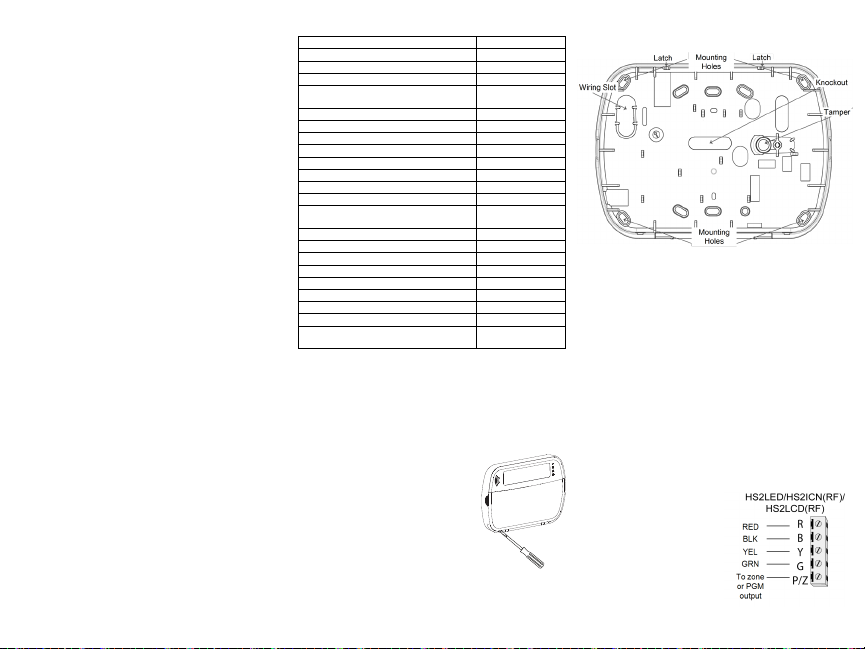
3. Run wire through wiring s lot or knockouts. Connect Corbus and
PGM/Zone w iring to keypad. Pl ace t amper switch into tamper
hole on backplate.
4. P lace keypad into backplate, ensuringthe wire is pushed back
into the wall as mucha s possible. Route the wire inside t he
keypad, ens uring high components are avoided. Snap the front
assembly closed, ensuring that there is no pressure t o the keypad
from the wire below.
NOTE: If any tension is found between the front keypad ass embly
and the w iring, open the keypad, reroute the wire and cl ose again.
Repeat these steps until t he keypad is closed properly.
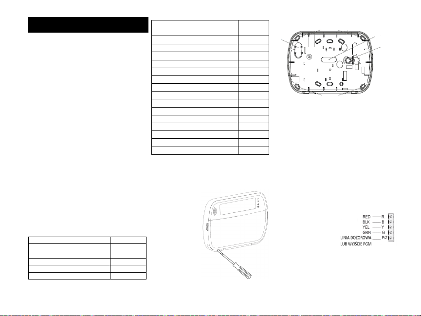
Wiring
1. Before wiring the unit, ensure that
all power (AC transformer and battery) is disconnected from the control panel.
2. Connect the four Corbus w ires
from the control panel (red, black,
yellow and green) to the keypad terminals. Refer to the diagram:
If programmed as an input, a device
- s uch as a door contact - may be
connected to the ‘P/Z’ terminal of
the keypad. This eliminates the need to run wires back to the
Page 3
control panel for the device. To connect the zone, run one wire
41
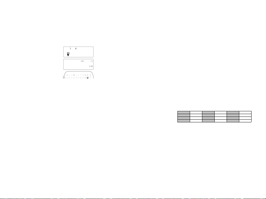
Toggle (X) <>
“Toggle name” Y/N
from the device to the ‘P/Z’ terminal and the other wire from the
device to the B (black) terminal. For powered devices, run the red
wire to the R (positive) terminal and the black wire to the B (negative) terminal. When using end of line supervision, connect the
zone according to one of t he configurations described i n the PowerSeries Neo Reference manual.
NOTE: For UL/ULC installations, the zone input is a supervised
type (SEOL/DEO L). The supervision res istor is 5600Ω. If no
EOL s upervision is used, there is a three foot maximum distance
required for the connected device. Use only in conjunction with
UL/ULC listed devices.
NOTE: This i nitiating device connected to this input contact is
not to be used for medical or fire applications.
3. If the ‘P/Z’ terminal is programmed as an output, a small relay
(such as DSC model RM-1 or RM-2) or buzzer or other DC operated device may be connected between the positive supply voltage
and the ‘P /Z’ terminal (max.load is 50mA).
NOTE: For UL/ULC-list ed install ations, use UL/ ULC lis ted
devices.
Apply Power
Once al l wiring is complete, and t he equipment is secured to the
buildings tructure with at le ast two s crews, apply power to t he
control panel:
1. Connect the battery leads to the battery.
2. Connect the AC transformer.
For more information on control panel power s pecifications, see
the P owerSeries Neo Reference manual.
Program the Keypad
1. P ress [*][8][Installer Code].
2. U se the [<][>] keys to navigate t hrought he menus or jump
directly to a s pecific s ection by
entering the s ection number.
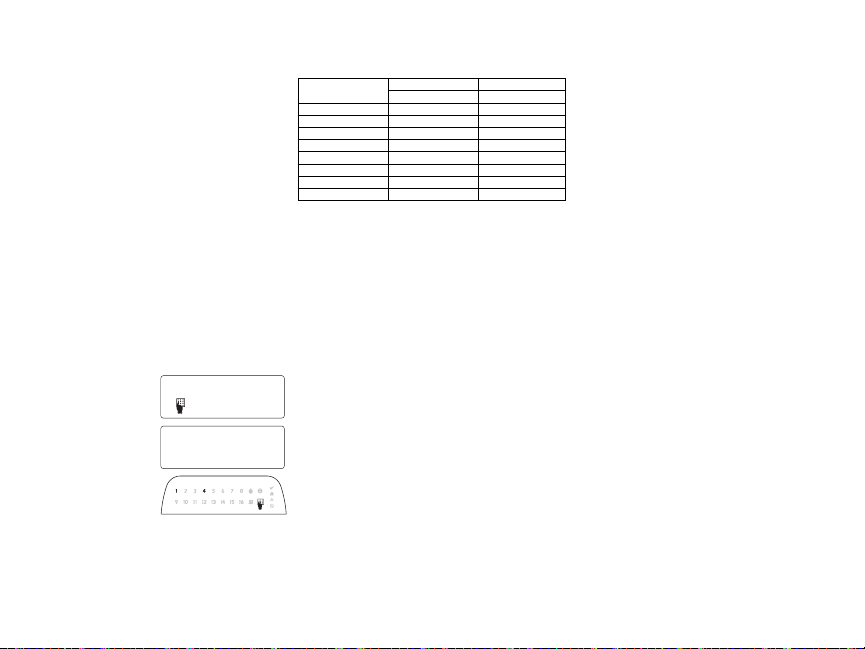
Programming consists of toggling on and off options in each
section or by populating data
fields. Toggle options are
enabled or disabled by pressing
the corresponding number on t he
keypad. F or example, to enable
toggle options 1 and 4, press the
[1] and [4] keys. All enabled
options are displayed (see the following diagram).
1. To input data, use the [<][>] keys to select a character then
press the keypad button for the number/letter.
2. U sing the [<][>] keys, scroll t o the next character and repeat
the procedure. For informationon enteringH EX data, refer to the
PowerSeries Neo Reference manual.
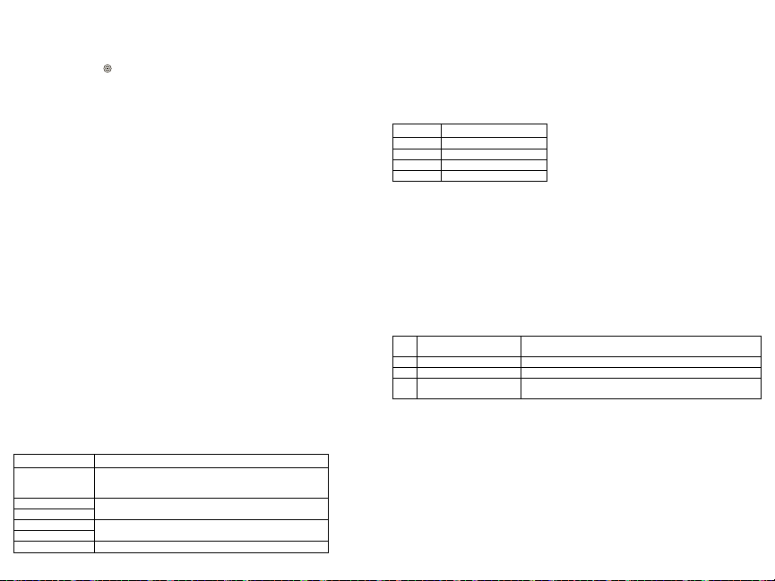
Language Programming
Enter [000][000]. Enter t he two-digit number corresponding to the
language desi red:
Table 2: Languages
01 = English
(default)
02 = Spanish 12 = Norwegian 22= Bulgarian
03 = Portuguese 13 = Danish 23 = Latvian
04 = French 14 = Hebrew 24 = Lithuanian
05 = Italian 15 = Greek 25 = Ukrainian
06 = Dutch 16 = Turkish 26 = S lovak
07 = Polish 17 = F FU 27 = Serbian
08 = C zech 18 = Croatian 28 = Est onian
09 = Finnish 19 = Hungarian 29 = Slovenian
Enroll the Keypad
Keypads can be enrolled automatically or manually. In either cas e,
the s erial number of the device is used as an identifier.
NOTE: If there is nokeypad enrolled on the system, once you
power up, the keypad wil l dis play the mes sage: Press any key to
enroll. Ot her keypads can then be enrolled from the first keypad.
Use one of the following enrollment options:
[902][000] AutoEnroll
When this mode is selected, the total number of keypads currently
enrolled is displayed on the keypad.
1. Enter [902][000] to begin the auto-enrollment of new keypads.
As each device is enrolled, the keypad displays t he model type,
serial number and s lot as signment. Keypads are ass igned to the
next available slot.
[902][001] ManualEnroll
To manually enroll individual keypads:
1. Enter [902][001] or use the [<][>] keys and press [*].
2. When prompted, enter t he serial number of the keypad foundon
the back of the device.
3. A n error tone is sounded if an invalid serial number is received.
Once enrolled, the device model, serial number and s lot as signment are displayed. Keypads are enrolled into the next available
slot for the device. The sl ot ass ignment can be changed using the
[<][>] keys.
4. To cancel the enrollment of a module, press [#].
NOTE: Once the maximum number of devices have been enrolled,
an error tone s ounds and a warning mess age is displayed.
10 = German 20 = Romanian
11 = Swedish 21 = Russian
[902][002] – Module Slot Assignment (LED, LCD,ICON)
This section is used t o change the slot number in w hich a module
is enrolled. To change the slot number:
1. Enter [902][002] or use the [<][>] keys and press [*].
2. Enter the s erial number of the module.
3. When prompted, enter t he new two-digit slot number. The previous sl ot ass ignment is replaced w ith the new one. An error tone
sounds if an invalid slot number is entered.
[902][003] – Module Slot Assignment (LCD Only)
Similarly to [002], this s ection is also used to change the s lot number of a module. With this option, however, the serial number is
not required. To change the s lot number:
1. Enter [902][003] or t he use the [<][>] keys and press [*].
2. U se the [<][>] keys to locate the module then press [*] to
select.
3. Enter the new two-digit slot number. The previous s lot as signment is replaced wit h the new one. A n error tone sounds if an
invalid slot number is entered.
[902][101] Unenroll Keypads
1. Enter [902][101] or use the [<][>] keys and press [*].
2. U se the [<][>] keys to s croll to the specific keypad to delete.
3. P ress [*] to s elect the module and when prompted, press [*]
again to delete it.
[903][101] Confirm Keypad
To confirm the enrollment of individual keypads and to locate them
physically:
1. Enter [903][101] or use the [<][>] and press [*].
2. U se the [<][>] keys to s croll to the applicable keypad. The module’s s erial number and slot number are displayed on the keypad
and the s tatus LEDs on the device flash.
3. To confirm the keypad, press [*]. If communication with a module is lost at the time of c onfirmation, a warning message is displayed for 1 s econdbefore exiting the sect ion.
Assign a Partitiontothe Keypad
The keypad must be assignedto a partition if s upervision or
keypad zones are required. Keypad as signments and keypad option
programming must be done at each keypad individually.
At each keypad installed on the s ystem:
1. P ress [*][8][Installer Code].
2. Enter [861]-[876] for Keypad Programmingand KeypadP artition
Mask, correspondingt o keypads 1-16.
3. P ress [*] for partition ass ignment.
4. Enter 01 to 08 for partition assignment or use the [<][>] keys to
scroll to the specific partition If partitioningi s not used, enter
[01]. For Global keypads, enter [00].
5. P ress [#] twice to exit programming.
6. Continue this procedure for each keypad until all have been
assi gnedt o the correct partiti on.
Page 4
Program Labels (LCD keypads)
1. P ress [*][8][Installer Code].
2. P ress [*] and use the [<][>] keys to s croll to Zone Labels and press [*] again.The first zone is displayed. Alte rnatively, enter, [000][001].
3. U se the [<][>] keys to s croll to the zone label to be programmedand press [*] or enter the zone number (e.g., 001, for zone label 1).
4. U se the [<][>] keys to s croll to the desired character’s location, using t he [<][>] keys.
5. Enter the number of the c orresponding character group until the desired character i s displayed (see
the following table). Example, press the “2” key three ti mes to enter the letter “F”. Press the “2” key
fourt imes to enter t he number “2”. P ress [*], then s croll to “Save”. Press [*] again to save the label.
To delete a character, use the [<][>] keys to move the cursor under the character, then press [0]. If any
key other than [<][>] is pressed before [0], the cursor moves one s pace to the right and deletes that
character.
[1]- A, B, C, 1 [5] - M, N, O, 5 [9] - Y, Z, 9, 0
[2]- D, E, F , 2 [6] - P, Q, R, 6 [0] - Space
[3]- G, H, I, 3 [7] - S, T, U, 7 [*] - Select
[4]- J, K, L, 4 [8] - V, W , X, 8 [#] - Escape
CHANGE CASE – Will toggle the next letter entries between upper case (A, B, C.. .) and lower case
letters (a, b, c. ..).
ASCII ENTRY – Used to enter uncommon characters. Valid entries range from 000 to 255. U se the
[<][>] keys to scroll through the characters or enter a 3-digit number from 000-255. P ress [*] to enter
the character into the l abel.
CLEAR TO END – Clears the display from the character where the cursor was located to the end of
the display.
CLEAR DISPLAY – Clears the e ntire label.
Continue from Step 2, until all labels are programmed.
Label Library
The Label Libraryi s a database of words commonly used when programming labels. Individual words
can be combined as needed (e.g., Front + Door). Each l ine of the display s upports a maximum of 14
characters. If a word will not fit on a li ne, s croll right until the cursor appears at the first character of
the s econd line and t hen add the w ord.
To program a custom label using the Label Library:
1. P ress [*][8][Installer Code][000][001].
2. Enter [001] (to program the label for zone 01), or use t he [<][>] keys to s croll to the Zone Labels
and then press [*]. The current label name is displayed for that zone.
3. P ress [*] to open the menu.
4. P ress [*] again to select the “Word Entry” option.
5. Enter the 3-digit number correspondingt o a word (see Words Library) or use the [<][>] keys to view
words in the library.
6. P ress [*] to s elect the word.
7. To add another word, repeat t he previous procedures from s tep 3.
8. To add a space, press the right s croll key [>].
9. To clear characters, select “Clear to End” or “Clear Display” from the menu.
10. To s ave the current l abel and exit, press [#].
Broadcast LCDLabels
If more than one LCD keypadis present on the system, labels programmedon one keypad will be
broadcast to all other LCD keypads, after the change is confirmed.
Change Brightness/Contrast/Buzzer
LCDKeypads
1. P ress [*][6][Master Code].
2. U se the [<][>] keys to s croll to either Bright Control, Contrast Control, or Buzzer Control.
3. P ress [*] to s elect one of the following set tings:
l Brightness/LED Bar Control -15 backlighting levels available.
l Contrast Control -15 display contrast levels available.
l Buzzer Control - 15buzzer control levels available.
4. U se the [<][>] keys to s croll to the desired setting.
Keypad Programming
1. P ress [*][8][Installer Code].
2. S elect one of the programming options identified in the following.
[860] Keypad Slot Number
Not for programming; the two-digit slot number is displayed for informational purposes only.
[861]-[876] Keypad ProgrammingSections
[000]Address of Partition
Default: 01
A 2-digit entry is required to as sign the keypad to a partition. Valid entries are 00-32.
NOTE: LED and ICON keypads must not be as signed as global keypads.
[001]-[005] Keypad Function Key Programming
To program a functionkey:
Press [*][8][Installer Code].
1. Enter [861]-[876] for keypad programming.
2. Enter [001]-[005] for function keys 1-5 or use the [<][>] keys and press [*].
3. Enter a 2-digit number to as sign a function key operation- [00]-[68]. S ee t he following table.
4. Repeat from s tep 3 until all function keys are programmed.
5. P ress [#] twice to exit Installer Programming.
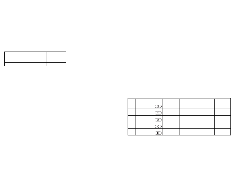
Table 3: Fu nction Key Assi gnment
Function Key Button Valid Range Default Function
[001] Key 1
[002] Key 2
[003] Key 3
[004] Key 4
[005] Key 5
Keypad FunctionKeys
Refer to your system instal lation manual for a complete lis t of available function key options.
[00]- Null [13]- Global A way Arm [31] - Local PGM Activate
[02]- Instant S tay Arm [14] - Global Dis arming [32] - Bypass Mode
[03]- Stay Arm [16] - [*][0] Quick Exit [33] - Bypass Recall
[04]- Away Arm [17] - Arm Interior [34]- User Programming
[05]- [*][9] No-Entry Arm [21] - [*][7][1]Command Output 1 [35] - Us er Functions
[06]- [*][4] Chime ON/O FF [22] - [*][7][2]Command Output 2 [37] - Time & Date Program
[07]- [*][6][----][4] System Test [23] - [*][7][3]Command Output 3 [39] - Trouble Dis play
[09]- Night A rm [24] - [*][7][4]Command Output 4 [40] - Alarm Memory
[12]- Global S tay Arm [29] - Bypass Group Recall [61]-[68] - P artition Select 1-8
00–68 03
00–68 04
00–68 06
00–68 22
00–68 16
Stay Arm |_____|_____|
Away Arm |_____|_____|
Chime ON/OFF |_____|_____|
Command Output 2 |_____|_____|
Quick Exit |_____|_____|
Page 5
[011] Keypad Input/Output Programming
1
2
7
8
9
12
10
3
11
13
4
5
6
14
15
16
17
Zone / PGM Number Default 000 |_____|_____|_____|
[012] Local PGM Output Pulse ActivationTime
|_______|_______| Minutes (00-99) |_______|_______| Seconds (00-99)
[021] First Keypad Options
Default Opt. ON OFF
ON |____| 1 Fire Key Enabled Fire Key Dis abled
ON |____| 2 Medical Key Enabled Medical Key Dis abled
ON |____| 3 Panic Key Enabled P anic Key Dis abled
ON |____| 4
NOTE: For EN50131-1/EN50131-3 compliant systems, section [021], options 1 and 2 s hall be OFF.
[022] Second Keypad Options
Default Opt. ON OFF
ON |____| 1 Local Clock Display ON Local Clock Display OF F
OFF |____| 2 Local Clock Dis plays 24-hr Clock Displays AM/PM
ON |____| 3 Auto Alarm Mem Scroll ON Auto Alarm Mem Scroll OFF
ON |____| 4 For Future Us e For Future Us e
OFF |____| 5 Power LED Enabled P ower LED Disabled
ON |____| 6 Power LED AC Prese nt ON Power LED AC Present OFF
ON |____| 7 Alarms Displayed While A rmed A larms N ot Dis played While Armed
OFF |____| 8 Auto-Scroll Open Zones ON Auto-Scroll O pen Zones OF F
[023] Third Keypad Options
Default Opt. ON OFF
OFF |____| 1 A rmed LED P ower Save Armed LED Off in Sleep Mode
ON |____| 2 Keypad Status Shows Stay A rm Keypad Status Shows Stay/Away Arm
OFF |____| 3 5th Terminal is PGM Output 5th Terminal is Zone Input
OFF |____| 7 Local Display of Temperature No Local Dis play of Temperature
OFF |____| 8 Low Temperature Warning Enabled
[030] Downloaded LCD Message
|_____|_____|_____|_____|_____|_____|_____|_____|_____|_____|_____|_____|_____|_____|_____|_____|
|_____|_____|_____|_____|_____|_____|_____|_____|_____|_____|_____|_____|_____|_____|_____|_____|
NOTE: Clock display (Section [022], Option 1) must be enabled.
[031] Downloaded LCD Message Duration
Default: 000 |_____|_____|_____| (Valid entries are 000-255, 000=Unlimited Ms g Dis play)
This number represents t he number of times the downloaded mess age must be cleared before it is permanently removed. This message can be cleared by pressing any key.
[041] Indoor Temperature Zone Assignment
Default: 000 |_____|_____|_____| (Valid entries a re 000-128)
[042] OutdoorTemperature Zone Assignment
Default: 000 |_____|_____|_____| (Valid entries a re 000-128)
Display Access Code When Programming
Display Xs WhenP rogramming
Access Codes
Low Temperature Warning
Disabled
[101]-[228] Door Chime for Zones
Default: 01 |_____|_____|
The keypad can be programmed to make up to four different chime s ounds for individual zones.
(e.g., for Zone 1, enter section [101], for Zone 2 enter section [102]).
01 6 beeps 04 Alarm Tone (4s duration)
02 Bing bing tone 05 Zone Name
03 Ding dong tone
[991] Reset Keypad Programming to Factory Defaults
1. P ress [*][8][Installer Code].
2. Enter [991].
3. U se the [<][>] keys to s croll to the applicable keypad.
4. P ress [*] to s elect the keypad.
5. Re-enter [Installer Code].
6. P ress [*] to reset the selected keypad to factory defaults
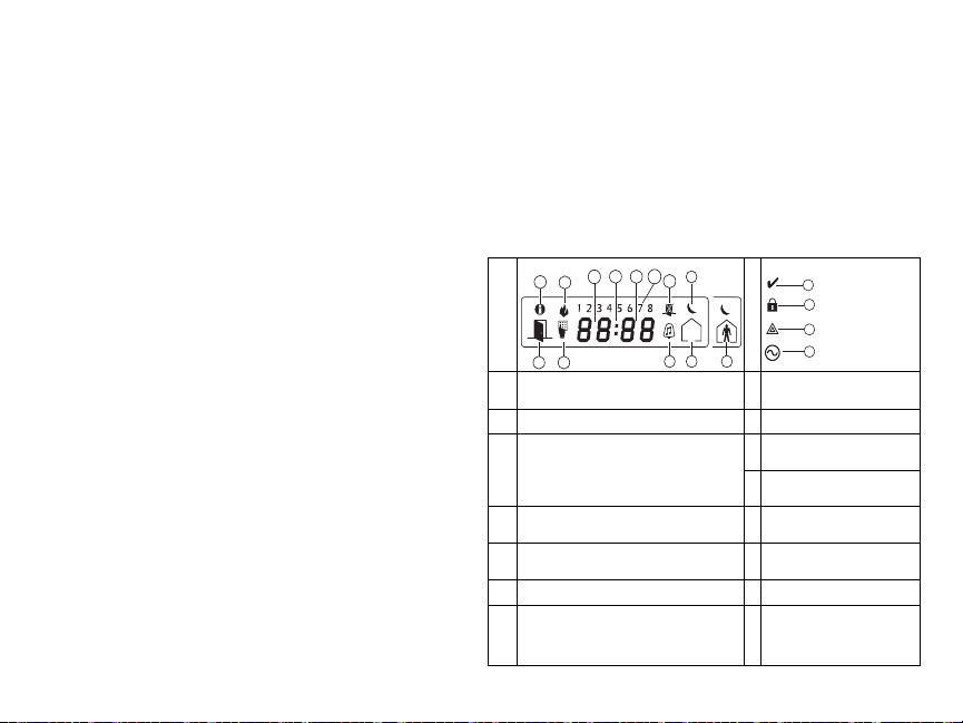
Keypad Symbols
Table 4: Keypad Disp lay Symbols
1 Memory – Indicates that alarms are in memory. 10
2 Fire – Indicates that fire alarms are in memory. 11
Clock Digits – These digits indicate the hour and
minutes when the local clock is active, and also
identify the zone when the OPEN or ALARM
3,4,5
icons are active. These digits scroll one zone per
secondfrom the lowest zone number to the
highest when scrolling through zones.
1 to 8 – These numbers display toggles or digits
6
in binarywhile theyare needed.
Bypass – Indicates that there are zones auto-
7
matically or manually bypassed.
Open – When zones are opened, this icon will
8
turnon and the open zones are displayed.
Program – If the s ystem is in Installer’s or
User’s Programming, or the keypad is busy, this
9
icon flashes. If an access code is required while
accessing star menus, this LED is on steadily to
indicate that the code is required.
Chime – Turns on when Door
Chime is enabledand off when
Door Chime is disabled.
Away – Indicates that t he panel
is armed in away mode.
Stay – Indicates that the panel i s
12
armedin stay mode.
Night – Indicates that the panel is
13
armedin night mode.
Ready Light (green)– If the
14
Ready light is on, the system is
ready for arming.
ArmedLight (red) – If the Armed
15
light is on, the system has been
armeds uccessfully.
System Trouble – Indicates that a
16
system trouble is active.
AC – Indicates that AC is
17
present at the main panel.
Page 6
Proximity (Prox) Tags Support (HS2ICNP/HS2ICNRFP/HS2LCDP)
The prox tag can perform any keypad function that would normally require a user access code. Pres ent
the tag to the tag reader ( ) or to the left of the keypad LCD.
AssignProximity Tags
Using a n LCD keypad:
1. P ress [*][5][Master/Supervisor Code].
2. Enter a 2-digit user code.
3. P ress 2.
4. P ass the enrolled tag near the t ag reader on the keypad.
Delete Proximity Tags
To delete a prox tag, select the user as outlined previously.Swipe the as sociated prox tag. The alarm
system recognizes the tag. Press [*] to delete when prompted.
LED Bar
On the HS2ICNP/HS2ICNRFP/HS2LCDP keypads, a blue LED bar indicates that a prox tag is
approaching.
- The LED bar flas hes three times when a valid prox tag i s beingread by the keypad.
- If the prox tag is invalid, the LED bar stays on ste adily and the keypad sounds an error tone.
- The brightness of the LED bar is adjustable from the [*][6] menu. Whent he backlight brightness i s
modified, the LED bar brightness is changed accordingly.
Downloading
The HS 2LCDRF/HS2ICNRF products can be programmed over DLS V. This auto-detects the keypad
type and downloads programming accordingly.
Wireless Device Setup and Programming (HS2ICNRF(P)x/HS2LCDRF(P)x)
This section describes how to enroll and program wireless devices such as contacts, motion sensors
and sirens on the alarm panel.
[804][000] EnrollWireless Devices
1. O nce the HSM2HOST is installed and enrolled on the al arm panel wi reless devices can be
enrolled using the following method: Enter Installer P rogramming section [804][000]:
2. When prompted, either activate the device (see device inst allation s heet) to enroll i mmediately or
enter a device ID number. Do the latter to pre-enroll devices then enroll them l ater at the customer
site.
The alarm panel determines the type of device being enrolled and presents the appropriate programming
options.
Table 5: W ireless Device Options
Device Type ProgrammingOptions
Zone
Wireless key
Siren
Repeater (01) Repeater label
3. U se the scroll keys or type i n the corresponding number to select an option.
(01) Zone type
(02) Partition assignment
(03) Zone label
(01) Partition assignment
(02) User label
(01) Partition assignment
(02) Siren label
4. S croll throught he available selections, key in a number or enter te xt as appropriate.
5. P ress [*] to accept and move to the next option.
6. O nce all options are configured, t he syst em prompts to enroll t he next device.
7. Repeat the process described above until all wi reless devices are enrolled.
NOTE: The configuration options listed above can be modified using [804][911] Modify Device.
[804][001]-[716] Wireless Device Configuration
To configure wi reless devices:
1. Enter Installer P rogrammingsection [804] then sel ect one of the following sub-sections:
Table 6: W ireless Zone Sub-Sections
Sub-Section Description
001-128 Configure wireless zones
551-556 Configure wireless sirens
601-632 Configure wireless keys
701-716 Configure wireless keypads
2. S elect a device to configure using the scroll keys or go directly to a specific device by entering a
hotkey.
3. U se the scroll buttons or enter a hot key to select a configuration option for the device. See device
sheets for details.
4. P ress [*] to accept and move to the next option.
5. O nce all options are configured, t he syst em returns to the base configuration menu.
Repeat the process described above to configure other wireless devices.
[804][801] RF Jam Detect
RF jam detection (continuous i nterfering transmiss ions on the radio network) can be turned on or off.
When on, RF jamming is logged and reported.
To configure RF jamming:
1. Enter Installer P rogrammingsection [804][801].
2. S elect one of the following options by s crolling or entering the hotkey:
Table 7: Jam Detect Options
00 Enabled/Disabled
01 UL 20/20-USA Continuous RF jamming for 20 seconds
02 EN 30/60-Europe 30 seconds of accumulated jamming within 60 seconds
03 C lass 6 30/60-British
3. P ress [*] to accept the s election.
4. P ress [#] to exit the s ection.
[804][802] Wireless SupervisionWindow
This option is used to program the le ngth of t ime a wireles s device can be absent from the s ystem
before a fault i s generated.
NOTE: For EN installations, 1 hour or 2 hours must be s elected.
When option06 is used, which configures the system to generate fault conditions after a device has
been detected as absent for 24 hours, s moke detectors generate a fault condition after a maximum of 18
hours when the 200s s upervision toggle option is disabled.
To program the Wireless SupervisoryWindow:
1. Enter Installer P rogrammingsection [804][802].
2. S elect one of the following options by s crolling or entering the hotkey
Jamming detection andreporting is enabled/disabled Note: Must
be Enabled for UL/ULC l isted installations.
As EN (30/60)but reportedonly if the jamming duration exceeds
5 minutes
Page 7
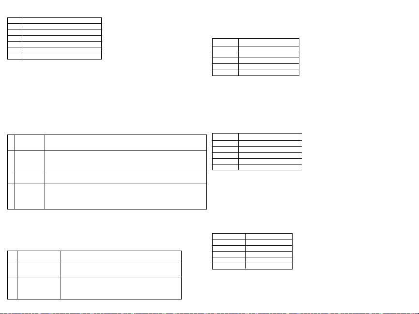
Table 8: W ireless S upervisory W indow Options
00 Enabled/Disabled
01 After 1 Hour
02 After 2 Hour
03 After 4 Hour
04 After 8 Hour
05 After 12 Hour
06 After 24 Hour
3. P ress [*] to accept the s election.
4. P ress [#] to exit the s ection.
NOTE: For UL Residential Burglary (UL1023), Home H ealth Care (UL1637), ULC Residential Burglary (ULC/ORD-C1023) instal lations, the maximum Supervision window s hall be set to 24 hours.
For UL Residential Fire (UL985) install ations, the maximum supervision window is set to 200s.
For UL Commercial Burglary(UL1610/UL365) and ULC Resi dential Fi re (ULC-S545), the maximum
supervision window shall be s et to 4 hours.
[804][810] Wireless Option 1
To program wireless options:
1. Enter Installer P rogrammingsection [804][810].
2. S elect one of the following options by s crolling or entering the hotkey.
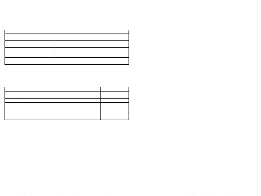
Table 9: W ireless Options
RF Delin-
01
quency
Wireless
Supervisory/
02
RF Jam
Alarm
Module
03
Tamper
Fire Super-
04
vision
3. P ress [*] to accept the s election and [#] to exit.
[804][841] Visual VerificationProgramming
To program wireless options:
1. Enter Installer P rogrammingsection [804][841].
2. S elect one of the following options by s crolling or entering the hotkey
Table 10: Vis ual Verification Su b-Sections
001 Visual Verification
002 View Time W indow
003 View Other Alarms
On: the s ystem cannot be armed if a wireless supervisory trouble exists. An R F
delinquency trouble is generated.
Off: wireless supervisory troubles do not prevent arming.
On: if a supervisory or jamming trouble occurs duringAway arming, the siren
activates and the event is logged and reported.
Off: supervisoryor RF jam troubles during Away armingdo not activate t he siren
or get logged and reported.
On: module tampers are loggedand reported.
Off: module tampers are not logged or reported.
On: fire devices are supervised every 200s econds. If the device fails to report
within this window, a supervision trouble is generated.
Off: fire devices follow the supervision window programmed in section 802, upto
a maximum of 18 hours. The supervisory window can be programmed with a
higher value, but detectors still go into fault after 18 hours.
On: Alarms trigger image capture fromPIR C ameras
Off: Alarms do not trigger image capture from PIR Cameras
01 Alarm + 5 Minutes
02 Alarm + 15 minutes
03 Alarm + 1 Hour
01 Fire key enabled/disabled
02 Duress key enabled/disabled
03 Medical key enabled/disabled
04 Panic key enabled/disabled
[804][901]-[905] Delete Wireless Devices
To delete wireless devices:
1. Enter Installer P rogrammingsection [804] then sel ect one of the following sub-sections:
Table 11: Module Label Su b-Sections
Sub-Section Description
901 Delete wireless zone devices
902 Delete wireless key
903 Delete sirens
904 Delete repeaters
905 Delete keypads
2. S elect a device to delete using the scroll keys or go directly to a specific device by entering a
hotkey.
3. P ress [*] to delete or [#] to exit.
[804][921]-[925] Replace Wireless Devices
Use this optionto replace a faulty device enrolled on t he syst em wit h another device of the same type
while maintainingt he configuration of the original. The faulty device does not need to be deleted. To
replace a wireless device:
1. Enter Installer P rogrammingsection [804] then sel ect one of the following sub-sections.
Table 12: Rep lace Device Sub -Sections
Sub-Section Des cription
921 R eplace wireless zone devices
922 R eplace wireless keys
923 R eplace sirens
924 R eplace repeater
925 R eplace keypad
2. P ress [*] to s elect a s ub-section. The first available device is displayed.
3. S elect a device to replace using the s croll keys or go to a specific device by entering a hotkey.
Press [*]. When prompted, a ctivate t he device (full enrollment) or enter the device ID (pre-enrollment).
A message i s displayed confirming enrollment.
[804][990][001- 005] Show All Devices
Use this section t o review wireless devices enrolled on t he syst em and to view s erial numbers ass ociated with each device.
To review wireless device information:
1. Enter Installer P rogrammingsection [804][990] then s elect one of the following sub-sections:
Table 13: Wi reless Device Sub-Sec tions
Sub-Section Descriptions
001 All zones
002 Repeaters
003 Sirens
004 Wireless keys
005 Keypads
2. P ress [*] to s elect a wi reless device type. The first available device is displayed.
3. U se the scroll keys to view t he enrolled devices.
NOTE: This option is not fully s upported by LED and ICON keypads.
Page 8
[904] Placement Testing Wireless Devices (LCD keypads only)
This test is used to determine RF signal status for wireless devices and can be performedat a system
keypad or at the i ndividual device. These inst ructions pertain to tes ting at the keypad. F or instructions
on placement tes ting at the device, refer to the instal lation sheet provided with the wireles s equipment. The following test modes are available:001-128 – Tes t wireless zones.
Table 14: Wi reless Device Placement Test Modes
001-128 Test wireless zones Test wireless devices individually byzone.
520 Test all repeaters
550 Test all sirens
600 Test all wireless keys
700 Test all keypads
Two tes t results are provided:
l
24-hour: Average results of signal s trength testing over a 24-hour period.
l
Now: Signal st atus res ults of the current tes t.
During testing, the Ready and Armed LED's flas h to indicate data is being received. A flas hing
Trouble LED indicates RF interference. The following status indicators may be displayed:
Table 15: Wi reless Device Status Indicators
LCD Status Repeater [905]
Strong Strong signal strength Repeater 1
Good Goods ignal s trength Repeater 2
Poor Poor signal strength Repeater 3
The device is operatingin 1-waymode only. The alarm panel can-
1-Way
not configure or control the device
Not Test Displayedas the Now result if no tes t was performed. Repeater 5
Always displayed as the 24-hourresult when testing wireless
None
keys.
NOTE: For UL/ULC installations, only STRONG signal levels are acceptable.
Troubleshooting
1. When attempting to as sign a zone number to a wi reless device, t he keypad responds with a long
beep.
l Ensure that the keypad is properly connected to the Corbus.
2. A fter entering the ESN of a wi reless device, t hen trippingit, the keypad does not indicate the zone
is open.
l Ensure the ESN has been entered correctly.
l Ensure that the zone is enabled for the partition (if partition programming is used).
l Ensure that the wireles s zone i s not assigned to a zone used by HSM2108 modules, an on-board
zone or a keypad zone.
l Ensure that the zone is programmed for something other than “Null Operation”. "Poor" or no res-
ults are received from a module placement test.
l Verify that youa re tes ting the correct zone.
l Verify the device is in range of the keypad. Test the device in the same room as the receiver.
l Confirm that the keypad is properly connected to the Corbus.
l Check that the zone is being test ed correctly. Refer t o the i nstructions that came wi th the device.
l Check that the batteries are working and install ed correctly.
l Look for large metal objects t hat may be preventing the signal from reaching the keypad.
Test eachenrolled wireless repeater.
521-528for repeaters 1-8.
Test eachenrolled wireless siren.
551-556for sirens 1-16
Test individual wireless keys. Once in this section, press a
button on the wireless key to beginthe test.
601-632for wireless keys 1-32.
Test eachenrolled keypad
701-716for keypads 1-16.
Repeater 4
Repeater 6
l The device must be located where consistent “Good” results are obtained. If several devices
show “P oor” res ults, or if panic pendants and w ireless keys operate inconsist ently, move the
receiver.
For s ystems compliant w ith EN50131-1 and EN50131-3 the HS 2LED keypad shall be used in conjunction with an LCD type keypad (HS2LCD(P) or HS 2LCDRF(P)8 or HS 2LCDWF(P)8) in order to
be able to review logged events and also to allow overriding of conditions that inhibit sett ing of the
alarm s ystem. The HS2LED keypad alone cannot s upport these functions.
Page 9

WordLibrary
Item # Text Item# Text Item # Text Item # Text Item # Text Item # Text Item # Text
001 Aborted 037 Closed 073 Feature 109 Library 145 Pool 181 Tamper 217 N
002 AC 038 Closet 074 Fence 110 Light 146 P orch 182 Temperature 218 O
003 Access 039 Closing 075 Fire 111 Lights 147 Power 183 Test 219 P
004 Active 040 Code 076 First 112 Living 148 Press 184 Time 220 Q
005 Activity 041 Communicator 077 Floor 113 Load 149 Program 185 To 221 R
006 Alarm 042 Computer 078 Force 114 Loading 150 Progress 186 Touchpad 222 S
007 All 043 Control 079 Foyer 115 Low 151 Quiet 187 Trouble 223 T
008 AM 044 Date 080 Freeze 116 Lower 152 Rear 188 Unbypass 224 U
009 Area 045 Daughter’s 081 Front 117 Main 153 Receiver 189 Unit 225 V
010 Arm 046 Degrees 082 Furnace 118 Master 154 Report 190 Up 226 W
011 Armed 047 Delay 083 Gallery 119 Mat 155 RF 191 West 227 X
012 Arming 048 Den 084 Garage 120 Medical 156 Right 192 Window 228 Y
013 Attic 049 Desk 085 Gas 121 Memory 157 R oom 193 Zone 229 Z
014 Auxiliary 050 Detector 086 Glass 122 Menu 158 Safe 194 0 230 Space
015 Away 051 Dining 087 Goodbye 123 Monoxide 159 Saver 195 1 231 ,
016 Baby 052 Disarmed 088 Gym 124 Mother’s 160 Schedule 196 2 232 017 Back 053 Door 089 Hallway 125 Motion 161 Screen 197 3 233 _ (Underscore)
018 Bar 054 Down 090 Heat 126 No 162 Second 198 4 234 *
019 Basement 055 Download 091 Hello 127 North 163 S ensor 199 5 235 #
020 Bathroom 056 Downstairs 092 Help 128 Not 164 Service 200 6 236 :
021 Battery 057 Drawer 093 High 129 Now 165 Shed 201 7 237 /
022 Bedroom 058 Driveway 094 Home 130 Number 166 Shock 202 8 238 ?
023 Bonus 059 Duct 095 House 131 Off 167 Shop 203 9
024 Bottom 060 Duress 096 In 132 Office 168 Side 204 A
025 Breezeway 061 East 097 Install 133 OK 169 Siren 205 B
026 Building 062 Energy 098 Interior 134 On 170 Sliding 206 C
027 Bus 063 Enter 099 Intrusion 135 Open 171 S moke 207 D
028 Bypass 064 Entry 100 Invalid 136 Opening 172 Son’s 208 E
029 Bypassed 065 Error 101 Is 137 Panic 173 Sound 209 F
030 Cabinet 066 Exercise 102 Key 138 Partition 174 South 210 G
031 Camera 067 Exit 103 Kids 139 Patio 175 Special 211 H
032 Canceled 068 Exterior 104 Kitchen 140 Pet 176 Stairs 212 I
033 Car 069 Factory 105 Latchkey 141 Phone 177 Stay 213 J
034 Carbon 070 Failure 106 Laundry 142 Please 178 Sun 214 K
035 Central 071 Family 107 Left 143 PM 179 Supervisory 215 L
036 Chime 072 Father’s 108 Level 144 Police 180 System 216 M
Page 10

Limited Warranty
+HUHE\'6& GHFODUHV WKDW WKLV GHYLFHLV LQ FRPSOLDQFH ZLWKWKH HVVHQWLDO
UHTXLUHPHQWVDQGRWKHUUHOHYDQWSURYLVLRQVRI'LUHFWLYH(&
7KH FRPSOHWH 577('HFODUDWLRQ RI&RQIRUPLW\ FDQEH IRXQG DW
KWWSZZZGVFFRPOLVWLQJVBLQGH[DVS[
&=('6& MDNRY¿UREFH SURKODģXMHŀH WHQWRY¿UREHNMH YVRXODGX VHYģHPL
UHOHYDQWQ¯PLSRŀDGDYN\VPÝUQLFH(&
'$1'6&HUNO¨UHUKHUYHGDWGHQQHNRPSRQHQWHQRYHUKROGHUDOOHYLNWLJHNUDYVDPW
DQGUHEHVWHPPHOVHUJLWWLGLUHNWLY(&
'87+LHUELMYHUNODDUW'6&GDWGLWWRHVWHOLQRYHUHHQVWHPPLQJLVPHWGHHLVHQHQ
EHSDOLQJHQYDQULFKWOLMQ(&
),1'6&YDNXXWWDDODLWWHHQW¦\WW¦Y¦QGLUHNWLLYLQ(&ROHQQDLVHWYDDWLPXNVHW
)5(3DUODSU«VHQWH'6&G«FODUHTXHFHGLVSRVLWLIHVWFRQIRUPHDX[H[LJHQFHV
HVVHQWLHOOHVHWDXWUHVVWLSXODWLRQVSHUWLQHQWHVGHOD'LUHFWLYH(&
*(5+LHUGXUFKHUNO¦UW'6&GD¡GLHVHV*HU¦WGHQHUIRUGHUOLFKHQ%HGLQJXQJHQXQG
9RUUDXVHW]XQJHQGHU5LFKWOLQLH(&HQWVSULFKW
*5(˂˜˞˱ˬ˲˭˞ˮ˹˪˱ˬ˯ˤ'6&ˡˤ˨˻˪ˢ˦˹˱˦˞˲˱˛ˤ˰˲˰˧ˢ˲˛ˢ˜˪˞˦˰˺˩˳˶˪ˤ˩ˢ˱˦˯
ˬ˲˰˦˻ˡˤ˯˞˭˞˦˱˛˰ˢ˦˯˧˞˦˩ˢ˹˨ˢ˯˱˦˯˙˨˨ˢ˯˰˴ˢ˱˦˧˚˯˞˪˞˳ˬˮ˚˯˱ˤ˯ˍˡˤˠ˜˞˯(&
,7$&RQOD SUHVHQWHOD'LJLWDO6HFXULW\&RQWUROVGLFKLDUDFKHTXHVWRSURGRWWRª
FRQIRUPHDLUHTXLVLWLHVVHQ]LDOLHG DOWUHGLVSRVL]LRQLULOHYDQWLUHODWLYHDOOD'LUHWWLYD
&(
125'6&HUNO¨UHUDWGHQQHHQKHWHQHULVDPVYDUPHGGHJUXQQOHJJHQGHNUDYRJ
ºYULJHUHOHYDQWHNUDYLGLUHNWLY()
32/'6&RĝZLDGF]DľHXU]ÇG]HQLHMHVWZ]JRGQRĝFL]]DVDGQLF]\PLZ\PDJDQLDPL
RUD]SR]RVWDĄ\PLVWRVRZQ\PLSRVWDQRZLHQLDPL'\UHNW\Z\:(
3253RUHVWHPHLRD'6&GHFODUDTXHHVWHHTXLSDPHQWRHVW£HPFRQIRUPLGDGH
FRP RV UHTXLVLWRVHVVHQFLDLV HRXWUDV GHWHUPLQD©·HV UHOHYDQWHVGD 'LUHFWLYD
(&
63$3RUODSUHVHQWH'6&GHFODUDTXHHVWHHTXLSRHVW£HQFRQIRUPLGDGFRQORV
UHTXLVLWRVHVHQFLDOHV\RWURVUHTXLVLWRVUHOHYDQWHVGHOD'LUHFWLYD(&
6:('6&EHNU¦IWDUK¦UPHGDWWGHQQDDSSDUDWXSSI\OOHUGHY¦VHQWOLJDNUDYHQRFK
DQGUDUHOHYDQWDEHVW¦PPHOVHUL'LUHNWLYHW(&
DigitalSecurityControls (DSC)warrants thatfora periodof 12monthsfrom thedate ofpurchase,the
productshallbefreeofdefectsinm aterialsand workmanshipundernormaluseandthatinfulfillmentof
anybreach ofsuch warranty,DSC shall,at itsoption, repair orreplacethedefective equipmentupon
returnoftheequipmenttoits repairdepot.This warrantyappliesonlytodefectsin partsandworkmanship
andnotto damageincurredinshippingorhandling,ordamageduetocausesbeyondthecontrol ofDigital
SecurityControlssuch aslightning, excessivevoltage,mechanical shock,water damage,ordamage
arisingout ofabuse, alterationor improperapplication ofthe equipment. Theforegoing warrantyshall
applyonly to the original buyer, and is andshall be in lieu ofany andall otherwarranties, whether
expressedor impliedand of allother obligationsor liabilities onthe partof Digital SecurityControls.
DigitalSecurityControlsneitherassumesresponsibilityfor, norauthorizesanyotherpersonpurportingto
actonits behalf tomodifyor tochangethiswarranty, nortoassume foritanyother warrantyorliability
concerningthisproduct.In noeventshallDigital Security Controlsbeliableforanydirect,indirector consequentialdamages,lossof anticipated profits,lossoftim e oranyotherlossesincurredby thebuyerin
connectionwiththepurchase,installationoroperationorfailureof thisproduct.Warning:DigitalS ecurity
Controlsrecommendsthattheentiresystem becompletely testedona regularbasis.However,despite
frequenttesting,anddueto,butnotlimitedto,criminaltamperingorelectricaldisruption,it ispossiblefor
thisproducttofail toperformas expected.ImportantInformation: Changes/modificationsnotexpressly
approvedby DSCcouldvoidthe user’sauthority tooperate this equipment.IMPORTANT -REA D
CAREFULLY:DSCS oftwarepurchasedwithorwithout ProductsandComponentsis copyrightedand
ispurchasedunderthe followinglicenseterms:T his End-UserLicenseAgreement (“EULA”)is alegal
agreementbetweenYou (thecompany, individualorentity whoacquired theSoftwareand anyrelated
Hardware)andDigital SecurityControls, adivisionof TycoS afety ProductsCanadaLtd. (“DSC”),the
manufacturerof the integrated security systems and the developer of the software and any related
productsorcomponents(“HARDWARE”)whichYouacquired.
IftheDSC softwareproduct(“SOFTWARE PRODUCT” or“SOFTWARE”)is intendedtobe accompaniedbyHARDWARE,andis NOTaccompaniedby newHARDWARE,Youm aynotuse,copyor
installthe SOFTWARE PRODUCT. TheSOFT WARE PRODUCTincludes computersoftware,
andmayincludeassociatedmedia,printedmaterials,and“online”orelectronicdocumentation.
Anysoftwareprovided along with theSoftware Product that is associatedwith aseparateend-user
licenseagreementis licensedtoYouundertheterms ofthatlicenseagreement.
By installing, copying,downloading, storing,accessing orotherwise using theSoftware Product,You
agreeunconditionallyto beboundby thetermsof thisEULA,evenifthis EULAis deemedtobea modificationofanypreviousarrangement orcontract.IfY oudo notagreetotheterms ofthisEULA, DSCis
unwillingtolicensetheSoftwareProducttoYou,andYouhavenorightto useit.
SOFTWARE PRODUCTLICENSE
TheSOFTWARE PRODUCT is protected bycopyright lawsandinternationalcopyright treaties,as
wellasotherintellectual propertylawsandtreaties.TheSOFTWARE PRODUCTis licensed,not
sold.
1.GRANT OFLICENSE ThisEULA grantsY outhefollowingrights:
(a)SoftwareInstallation andUse- Foreach licenseYouacquire, Youmayhave onlyonecopyof the
SOFTWARE PRODUCTinstalled.
(b)Storage/NetworkUse -The SOFTWARE PRODUCTm aynot beinstalled,accessed,displayed,
run,sharedorusedconcurrentlyonorfrom differentcomputers,includinga workstation,terminalorother
digitalelectronic device(“Device”). Inother words,if Youhave severalworkstations, Youwill haveto
acquirea licenseforeachworkstationwheretheSOFTWARE will beused.
(c)BackupCopy-Youm aymakeback-upcopiesoftheSOFT WAREPRODUCT, butYoum ayonly
haveonecopyperlicenseinstalledatanygiventime. Youmayusetheback-upcopysolelyforarchival
purposes.Except as expresslyprovidedin thisEULA, You may nototherwise make copiesof the
SOFTWARE PRODUCT,includingtheprintedmaterialsaccompanyingtheSOFTWARE.
2.DESCRIPTIONOF OTHER RIGHTS ANDLIMITAT IONS
(a)LimitationsonReverseEngineering,Decompilationand Disassembly- Youmaynotreverse engineer,decompile,ordisassembletheSOFTWARE PRODUCT, except andonlytotheextentthatsuch
activityis expresslypermittedbyapplicablelawnotwithstandingthislimitation.Youm aynotmakeany
changesormodificationsto theSoftware,withoutthewritten permissionofanofficerofDSC. Youmay
notremoveanyproprietarynotices, marksor labelsfromthe SoftwareProduct.Youshallinstitute reasonablemeasurestoensurecompliancewiththetermsandconditionsofthisE ULA.
(b)Separationof Components- TheSoftware Productis licensedasa singleproduct. Itscomponent
partsmay notbeseparatedforuseonmorethanoneHARDWARE unit.
(c)SingleINTEGRATEDPRODUCT - IfY ouacquiredthis SOFTWARE withHARDWARE,then
theSOFTWARE PRODUCT is licensedwiththeHARDWAREasa singleintegratedproduct.Inthis
case,theSOFTWARE PRODUCTmay onlybeusedwiththeHARDWARE assetforthinthis
EULA.
(d)Rental -Youmay notrent,leaseorlendtheSOFTWARE PRODUCT.You maynotmakeit availabletoothersor postit onaserverorwebsite.
(e)SoftwareProductTransfer-Youm aytransferallof YourrightsunderthisEULA onlyas partofa permanentsale or transferof the HARDWARE, providedYou retain no copies,You transfer allof the
SOFTWARE PRODUCT (including all component parts, the media and printed materials, any
upgrades and this EULA), and provided the recipient agrees to the terms of this EULA. If the
SOFTWARE PRODUCT is anupgrade, any transfer must also include all prior versions of the
SOFTWARE PRODUCT.
(f)Termination-Withoutprejudicetoanyotherrights,DSC may terminatethisEULA if Youfailtocomplywith the terms andconditions ofthis EULA. In suchevent, You mustdestroy all copiesof the
SOFTWARE PRODUCTandallof itscomponentparts.
(g)Trademarks-T hisEULA doesnotgrantYouanyrightsin connectionwithanytrademarksorservice
marksofDSC oritssuppliers.
3.COPYRIGHT - All titleand intellectual property rightsin and to theSOFTWARE PRODUCT
(includingbut not limited to anyimages, photographs, and text incorporatedinto the SOFTWARE
PRODUCT),theaccompanying printedm aterials,and anycopiesof theSOFTWARE PRODUCT,
areownedby DSC or its suppliers. You may not copy the printed materials accompanying the
SOFTWARE PRODUCT.All title andintellectualpropertyrights inandtothe contentwhichmaybe
accessedthroughuseoftheSOFT WAREPRODUCT are thepropertyoftherespectivecontentowner
andmaybeprotectedbyapplicablecopyrightor otherintellectual propertylawsandtreaties.T hisEULA
grantsYou norightstousesuchcontent.All rightsnotexpresslygrantedunderthisEULAarereservedby
DSCandits suppliers.
4.EXPORT RESTRICTIONS- You agreethat Youwill not exportor re-export theSOFTWARE
PRODUCT toanycountry,person,orentitysubjectto Canadianexportrestrictions.
5.CHOICEOF LAW-T his SoftwareLicenseAgreement is governedby thelawsof theProvinceof
Ontario,Canada.
6.ARBITRATION -All disputesarisinginconnectionwiththisAgreementshallbedeterminedbyfinal
andbindingarbitrationinaccordancewiththeArbitrationAct,andthepartiesagreetobe boundbythearbitrator’sdecision.TheplaceofarbitrationshallbeToronto,Canada,andthelanguageofthearbitrationshall
beEnglish.
7.LIMITED WARRANTY
(a)NOWARRANTY -DSC PROVIDES THES OFTWARE “AS IS”WITHOUT WARRANTY.
DSC DOES NOT WARRANT THAT THE SOFTWARE WILL M EET YOUR
REQUIREMENTS OR THAT OPERATION OF THE S OFTWARE WILL BE
UNINTERRUPTEDOR ERROR-FREE.
(b)CHANGES IN OPERATING ENVIRONMENT -DSC shall not be responsiblefor problems
causedbychangesin theoperatingcharacteristicsoftheHARDWARE, orforproblemsin theinteraction
oftheSOFTWARE PRODUCTwith non-DSC-SOFTWARE orHARDWARE PRODUCTS.
(c)LIMITATIONOF LIABILITY;WARRANTY REFLECTS ALLOCATION OF RISK- INANY
EVENT, IF ANY STATUTE IMPLIES WARRANTIESOR CONDITIONSNOT STAT EDIN
THIS LICENSE AGREEMENT, DSC’S ENTIRE LIABILITY UNDER ANY PROVISION OF
THIS LICENSE AGREEMENT SHALLBE LIMITED TOT HEGREATE ROF THE AMOUNT
ACTUALLY PAID BY YOU TO LICENSE THE S OFTWARE PRODUCT AND FIVE
CANADIAN DOLLARS (CAD$5.00). BECAUSE SOME JURISDICTIONS DO NOT ALLOW
THE EXCLUSIONOR LIMITATIONOF LIABILITY FOR CONSEQUENTIALORINCIDENTAL
DAMAGES, THE ABOVELIMITAT IONMAY NOT APPLY TOYOU.
(d)DISCLAIMER OF WARRANTIES - THIS WARRANTY CONTAINS THE ENTIRE
WARRANTY AND SHALL BE IN LIEU OF ANY AND ALL OTHER WARRANTIES,
WHETHER EXPRESSED OR IMPLIED (INCLUDING ALL IMPLIED WARRANTIES OF
MERCHANTABILITY ORFITNESS FORA PARTICULARPURPOSE)AND OF ALLOTHER
OBLIGATIONS OR LIABILITIES ON THE PART OF DSC. DSC MAKES NO OTHER
WARRANTIES.DSC NEITHER ASSUMES NOR AUTHORIZES ANY OTHER PERSON
PURPORTINGTOA CT ONITS BEHALF TO MODIFYOR TO CHANGE THIS WARRANTY,
NORTO ASSUME FORIT ANY OTHER WARRANTYOR LIABILITYCONCERNINGTHIS
SOFTWARE PRODUCT.
(e) EXCLUSIVE REMEDY AND LIMITATION OF WARRANTY - UNDER NO
CIRCUMSTANCES SHALL DSC BE LIABLE FOR ANY SPECIAL, INCIDENTAL,
CONSEQUENTIALOR INDIRECTDAM AGES BASEDUPON BREACH OFWARRANTY,
BREACHOF CONTRACT, NEGLIGENCE, STRICT LIABILITY, OR ANY OTHER LEGAL
THEORY.SUCH DAMAGES INCLUDE, BUT ARE NOTLIMITED TO,LOSS OFPROFITS,
LOSSOF THE SOFTWARE PRODUCT OR ANY ASSOCIATED EQUIPMENT, COST OF
CAPITAL,COST OF SUBSTITUTE OR REPLACEMENT EQUIPMENT,F ACILITIES OR
SERVICES, DOWN TIME, PURCHASERS TIME , THE CLAIMS OF THIRD PARTIES,
INCLUDINGCUSTOMERS,A NDINJURYT OPROPERTY.
WARNING: DSC recommends that the entiresystem be completely testedon a regular basis.
However,despite frequenttesting, and dueto, butnot limited to,criminal tamperingor electrical disruption,it ispossibleforthisSOFT WAREP RODUCT tofailto performas expected.
FCC ComplianceStatement
CAUTION:Changesorm odifications notexpresslyapprovedby DSC couldvoid yourauthorityto use
thisequipment.This equipmentgeneratesandusesradio frequencyenergyandif notinstalledandused
properly,in strict accordancewith themanufacturer’s instructions,m ay causeinterferenceto radioand
televisionreception.It hasbeentype testedand foundtocomply withthelimits forClass Bdevicein
accordancewiththespecificationsinSubpart“B”ofPart15of FCC Rules,whicharedesignedtoprovide
reasonableprotectionagainstsuch interferenceinany residential installation.However, thereisno guaranteethatinterferencewill notoccur ina particularinstallation.If thisequipmentdoescauseinterference
totelevisionorradioreception,whichcanbe determinedbyturningtheequipment offandon,theuseris
encouragedto tryto correcttheinterferencebyoneormoreofthefollowingm easures:Re-orientthereceivingantenna;Relocatethealarm controlwithrespectto thereceiver;Movethe alarm controlawayfrom
thereceiver;Connectthealarmcontrol intoadifferentoutletsothat alarm controlandreceiverareon differentcircuits. Ifnecessary, theusershouldconsultthedealeroran experiencedradio/television technicianforadditionalsuggestions. Theusermayfind thefollowingbookletprepared bytheFCC helpful:
“Howto Identify andResolve Radio/TelevisionInterferenceProblems”. Thisbooklet isavailablefrom
theU.S.GovernmentPrintingOffice,Washington,D.C.20402,Stock#004-000-00345-4.
Models: HS2LCDRF9, HS2LCDRFP9, HS2ICNRF9, HS2ICNRFP9 (operating in 912-919MHz
band)arecompliantwith applicableFCC Part15.247andIC RSS-210 rules.WARNING!T ocomply
withFCC andIC RFexposure compliancerequirements, theHS2LC-DRF (P)9or HS2ICNRF(P)9
keypadsshouldbelocatedat adistanceofatleast 20cm fromall personsduringnormaloperation.The
antennasusedforthisproductm ustnotbeco-locatedoroperatedin conjunctionwithanyotherantennaor
transmitter.Thisdevice complieswithF CC RulesPart15 andwithIndustry Canadalicense-exempt
RSS standard(s). Operationissubject tothe followingtwo conditions:(1) This devicemay notcause
harmfulinterference,and(2)thisdevicemust acceptanyinterferencethat may bereceived orthatm ay
causeundesiredoperation.IC:160A- HS2KRFP9.The term "IC" beforetheradiocertificationnumber
onlysignifiesthatIndustry Canadatechnicalspecifications weremet. Lepresent appareilestconforme
auxCNRd'IndustrieCanadaapplicablesauxappareilsradioexemptsdelicence.L'exploitationestautoriseeauxdeuxconditions suivantes:(1)l'appareil nedoitpas produiredebrouillage,et (2)l'utilisateurde
l'appareildoit acceptertout brouillageradioelectriquesubi,m eme si le brouillageest susceptibled'en
compromettrelefonctionnement.OperatingInstructionsshallbemadeavailabletotheuser.
TheModel HS2LED,HS2LCD(P),HS2ICN(P),HS2LCDRF(P)8,HS2ICNRF(P)8 Keypadshave
beencertifiedby Telefication accordingto EN50131-1:2006+ A1:2009,EN50131-3:2009for Grade2,
ClassII.EN50131-1Grade2/ClassII.T hisInstallationSheetappliesto thefollowingmodels:HS2LED,
HS2ICN, HS2ICNP, HS2ICNRFx, HS2ICNRFPx, HS2LCD, HS2LCDP, HS2LCDRFx and
HS2LCDRFPx;x = 9wherethe system operatesin 912-919MHz, 8wherethesystem operatesin
868MHzband,and4 wherethesystemoperatesin 433MHzband.
©2014TycoSecurityProducts.All RightsReserved.T oronto,Canada• www.dsc.com
TechSupport:1-800-387-3630(Canada,US),905-760-3000
Page 11
Klawiatury HS2LED/HS2ICN(P)(RF)/HS2LCD(RF)(P) są kompatybilne z
Spec
ykacja techniczna
Zakres temperatur pracy: od -10ºC do +55ºC.
Dopuszczalna wilgotność: 93% bez kondensacji.
Stopień ochrony obudowy: IP30, IK04.
Napięcie zasilania: 13.8 VDC.
Komunikacja z centralą za pomocą 4 przewodowej magistrali.
Dodatkowy zacisk do wykorzystania jako linia dozorowa* lub
wyjście PGM.
Pobór prądu dla klawiatur HS2LED / HS2ICN(P) / HS2LCD(P) /
HS2ICNRF(P) / HS2LCDRF(P): 55mA (tryb czuwania)/105mA (maks.).
Sabotaż oderwania od ściany.
5 programowalnych przycisków funkcyjnych.
Diody LED: Gotowość (zielona), Dozór (czerwona), Usterka (żółta),
Zasilanie AC (zielona).
Wymiary: 168mm x 122mm x 20mm
Waga: 260g
Zintegrowany czujnik niskiej temperatury.
Częstotliwość pracy: 868 MHz (HS2ICNRF8/HS2LCDRF8).
Obsługa maksymalnie do 128 linii bezprzewodowych (tylko
klawiatury RF).
*Uwaga! Linia klawiaturowa nie może być zaprogramowana jako linia
Pożarowa lub 24h.
Zawartość zestawu handlowego
W skład zestawu handlowego wchodzą następujące elementy:
Montaż urządzenia
Klawiaturę należy zamontować w miejscu suchym i bezpiecznym, łatwo
dostępnym dla użytkownika systemu.
Demontaż klawiatury z podstawy
Włożyć końcówkę płaskiego
wkrętaka do otworów
znajdujących się po prawej i
lewej stronie dolnej części
klawiatury. Delikatnie
podważyć przednią część
obudowy. Pozwoli to na
zdjęcie przedniego panelu
klawiatury i montaż podstawy
do powierzchni montażowej.
Montaż klawiatury na ścianie i doprowadzenie przewodów
1. Należy przymocować podstawę obudowy do ściany za pomocą 4
wkrętów dostarczonych w zestawie.
2. W przypadku korzystania z sabotażu oderwania od ściany, przykręcić
płytkę sabotażu do ściany.
3. Przełożyć przewody przez otwór lub odpowiednie przepusty po
usunięciu zaślepek. Podłączyć magistralę i zacisk P/Z. Umieścić
gumowy styk sabotażowy w gnieździe podstawy.
4. Umieścić klawiaturę na podstawie upewniając się, że przewód jest
maksymalnie dosunięty do ściany. P rzewód należy poprowadzić
wewnątrz klawiatury omijając elementy elektroniczne o większej
wysokości. Następnie należy zatrzasnąć panel przedni i upewnić się
czy panel nie naciska zbyt mocno na przewód.
Uwaga! Jeżeli panel zbyt mocno naciska na przewód, należy ponownie
otworzyć klawiaturę i zmienić trasę przewodu. Powyższe kroki należy
powtórzyć aż do poprawnego zamknięcia klawiatury.
Podłączenia
1. Przed podłączeniem przewodów zasilanie centrali alarmowej musi być
wyłączone (transformator i akumulator).
2. Podłączyć 4 przewody magistrali komunikacyjnej Corbus z centrali
alarmowej (czerwony, czarny, żółty i zielony) do zacisków klawiatury
zgodnie z rysunkiem.
3. P o zaprogramowaniu wejścia P/Z
jako linia dozorowa, do zacisku P/Z
klawiatury można podłączyć np.
kontaktron drzwiowy. Pozwala to
wyeliminować potrzebę
prowadzenia dodatkowego
przewodu do centrali alarmowej.
Aby podłączyć linię klawiaturową,
należy poprowadzić jeden przewód od czujki do zacisku P/Z,
natomiast drugi przewód do zacisku B. Dla czujek które wymagają
zasilania, należy poprowadzić przewody zasilające urządzenie do
zacisku R („+” zasilania) i do zacisku B („-” zasilania). Jeżeli w systemie
używane są rezystory parametryczne EOL, linię należy podłączyć
zgodnie z konguracją opisaną w instrukcji instalacji i programowania
centrali alarmowej.
Instrukcja instalacji
HS2LED/ICN(RF)/LCD(RF)
1 x klawiatura
4 x śruby montażowe
2 rezystory parametryczne
Naklejka na klapkę klawiatury
1 x styk sabotażowy
1 x instrukcja instalacji
HSICN(RF)P/LCD(RF)P
1 x klawiatura
4 x śruby montażowe
2 rezystory parametryczne
Naklejka na klapkę klawiatury
1 x styk sabotażowy
1 x instrukcja instalacji
Bezprzewodowa czujka dymu PG8926
Bezprzewodowa czujka dymu i temperatury PG8916
Bezprzewodowa czujka tlenku węgla PG8913
Bezprzewodowa czujka PIR PG8904
Bezprzewodowa czujka PIR z kamerą PG8934
Bezprzewodowa kurtynowa czujka PIR PG8924
Bezprzewodowa dualna czujka (PIR + MW) PG8984
Bezprzewodowa lustrzana czujka PIR PG8974
Bezprzewodowa zewnętrzna czujka PIR PG8994
Bezprzewodowa czujka zbicia szyby PG8912
Bezprzewodowa czujka wibracyjna PG8935
Bezprzewodowa czujka zalania wodą PG8985
Bezprzewodowa czujka temperatury PG8905
Zewnętrzna sonda temperatury (wymaga PG8905) PGTEMP-PROBE
Bezprzewodowy pilot PG8939
Bezprzewodowy pilot PG8929
Bezprzewodowy pilot napadowy PG8938
Bezprzewodowy pilot dwu przyciskowy PG8949
Bezprzewodowy sygnalizator wewnętrzny PG8901
Bezprzewodowy sygnalizator zewnętrzny PG8911
Bezprzewodowy retransmiter PG8920
Bezprzewodowy kontaktron PG8975
Bezprzewodowy kontaktron z wyjściem AUX PG8945
Otwory montażowe
Otwory montażowe
Otwory na
przewody
Płytka
sabotażu
Zaślepka
Zatrzask
Zatrzask
centralami PowerSeries Neo HS2016/32/64, HS2016-4 oraz HS2128.
Klawiatury wersji RF posiadają zintegrowany odbiornik radiowy.
Page 12
[902]>[000] Przypisywanie automatyczne
Po wyborze tej metody na klawiaturze zostanie wyświetlona informacja o
wszystkich przypisanych klawiaturach w systemie.
Wprowadzić [902][000] w celu rozpoczęcia procesu automatycznego
przypisania nowo podłączonych klawiatur/modułów do magistrali. Po
przypisaniu modułów klawiatura wyświetli model modułu, jego numer
seryjny oraz adres do którego moduł został przypisany.
[902]>[001] Przypisywanie ręczne
By ręcznie przypisać klawiatury:
1. Wejść do sekcji [902][001], lub użyć kursorów i nacisnąć [*].
2. Po wejściu do podsekcji wprowadzić numer seryjny klawiatury, który
znajduje się na naklejce z tyłu obudowy urządzenia.
3. Klawiatura wygeneruje sygnał błędu jeżeli wprowadzono nieprawidłowy
numer seryjny. Po poprawnym przypisaniu urządzenia klawiatura
wyświetli informację o numerze seryjnym oraz adresie do którego moduł
został przypisany. Klawiatury zostają przypisane do pierwszego wolnego
adresu. Przy użyciu kursorów [<][>] istnieje możliwość zmiany adresu
klawiatury.
4. By wyjść z trybu przypisywania modułów należy nacisnąć [#].
Uwaga! W przypadku przypisania maksymalnej ilość urządzeń klawiatura
wygeneruje sygnał błędu i wyświetli odpowiedni komunikat.
[902]>[002] Zmiana adresu klawiatury (LED, LCD, Ikonowe)
Sekcja umożliwia zmianę adresu klawiatury, która jest przypisana. Aby
zmienić adres klawiatury należy:
1.Wejść do sekcji [902][002], lub użyć kursorów [<][>] i nacisnąć [*].
2.Wprowadzić numer seryjny modułu.
3.Wprowadzić dwucyfrowy nowy adres klawiatury. Poprzedni adres
klawiatury zostanie zmieniony na nowo wprowadzony. Klawiatura
wygeneruje sygnał błędu w przypadku wprowadzenia błędnego adresu.
[902]>[003] Zmiana adresu klawiatury (Tylko LCD)
Podobnie jak w sekcji [002] sekcja ta umożliwia zmianę adresu klawiatury,
z tą różnicą, że nie jest wymagany numer seryjny klawiatury. Aby zmienić
adres klawiatury należy:
1.Wejść do sekcji [902][003], lub użyć kursorów i nacisnąć [*].
2.Użyć przycisków kursorów [<][>] by wybrać klawiaturę po czym wcisnąć
[*].
3.Wprowadzić dwucyfrowy nowy adres klawiatury. Poprzedni adres
klawiatury zostanie zmieniony na nowo wprowadzony. Klawiatura
wygeneruje sygnał błędu w przypadku wprowadzenia błędnego adresu.
[902]>[101] Usuwanie klawiatury
1.Wprowadzić [902][101], lub użyć kursorów i nacisnąć [*].
2.Przy użyciu kursorów wybrać klawiaturę która ma zostać usunięta.
3. Nacisnąć [*] by wybrać moduł, następnie nacisnąć [*] ponownie by
usunąć moduł.
[903]>[101] Potwierdzenie klawiatury
By potwierdzić klawiaturę należy:
1.Wprowadzić [903][101], lub użyć kursorów i nacisnąć [*].
2.Przy użyciu kursorów [<][>] wybrać klawiaturę i nacisnąć [*] by
zatwierdzić. Na klawiaturze zostanie wyświetlony numer seryjny modułu
oraz jego adres, dodatkowo na potwierdzanym module zaczną migać
diody statusu LED. Nacisnąć [*] by potwierdzić. Jeżeli podczas procesu
potwierdzania system utracił komunikację z modułem, na klawiaturze
zostanie wyświetlony przez okres 1 sekundy odpowiedni komunikat po
czym system wyjdzie z trybu potwierdzania.
Przypisanie klawiatury do podsystemu
Klawiaturę należy przypisać do podsystemu. Dla każdej klawiatury z osobna
należy zaprogramować opcje oraz przypisać do wybranych podsystemów.
Na każdej klawiaturze w systemie należy:
1. Wejść w tryb programowania instalatorskiego [*][8][kod instalatora].
2. Wprowadzić numer sekcji [861]-[876] (klawiatury od 1 do 16).
3. Nacisnąć [*] w celu wejścia do funkcji wyboru podsystemu.
4. Wprowadzić dwu cyfrowy numer podsystemu od 01 do 08. Jeżeli
system nie jest podzielony na podsystemy wprowadzić [01]. Dla
klawiatur globalnych wprowadzić [00].
5. Nacisnąć dwukrotnie [#] by wyjść z trybu programowania.
6. Powtórzyć procedurę dla każdej klawiatury w systemie.
Programowanie nazw linii (tylko klawiatury LCD)
1. Wprowadzić sekwencję [*][8][Kod instalatora].
2. Następnie nacisnąć [*] i za pomocą przycisków kursorów [<][>] przejść
do opcji „Nazwy linii” i nacisnąć [*] ponownie. Zostanie wyświetlona
nazwa 1 linii, alternatywnie nacisnąć [000][001].
3. Przy użyciu kursorów [<][>] przejść do numeru nazwy linii która ma być
programowana i nacisnąć [*], lub bezpośrednio wprowadzić numer linii
(np. Dla linii 1 wprowadzić [001]).
4. Przy użyciu kursorów, przejść do litery która ma zostać zmieniona.
5. Nacisnąć przycisk [1] do [9] odpowiadający żądanej literze (patrz tabela
poniżej). Pierwsze naciśnięcie przycisku spowoduje wyświetlenie
pierwszej litery. Kolejne naciśnięcie tego przycisku spowoduje
wyświetlenie kolejnej litery. Przykład: nacisnąć przycisk „2” trzy razy by
wprowadzić literę „F”, nacisnąć przycisk „2” cztery razy by wprowadzić
cyfrę 2. Po zakończeniu programowania nazwy, należy nacisnąć
przycisk [*], przejść do opcji “ZAPISZ”, następnie nacisnąć [*]. By
skasować literę, za pomocą kursorów, przejść podkreślnikiem pod
literę która ma zostać skasowana i nacisnąć [0]. Jeżeli naciśnięto inny
przycisk niż [<][>] przed naciśnięciem [0], podkreślnik zostanie
przesunięty o jedno pole w prawo i skasuje tą literę.
Zmiana duże/małe - pozwala na wybór pisowni z wielkiej (A, B, C) lub małej
litery (a, b, c).
Podaj znak ASCII - pozwala na wprowadzanie polskich znaków (ś, ć, ż, ń
itp.). Przy użyciu kursorów <> wybrać odpowiedni znak. Nacisnąć [*] w
zaakceptować wybór. Dane z zakresu 000-255.
Kasuj do końca - wykasuje wszystkie znaki z wyświetlacza od punktu
umieszczeni kursora.
Kasuj wszystkie - wykasuje wszystkie znaki z nazwy linii.
Biblioteka nazw
Biblioteka nazw jest bazą słów najczęściej używanych podczas
programowania nazw linii. Słowa dostępne w bibliotece można łączyć w
nazwy (przykład: Drzwi + F rontowe). W każdym z dwóch wierszy
wyświetlacza można zaprogramować po 14 znaków.
By zaprogramować nazwy linii korzystając z biblioteki nazw należy:
1. Wprowadzić [*][8][kod instalatora],[000],[001]
2. Wprowadzić [001] (by programować nazwę 1 linii), lub przy użyciu
kursorów przejść do opcji „Nazwy linii” i nacisnąć [*]. Na klawiaturze
zostanie wyświetlona nazwa wybranej linii.
4. Jeżeli zacisk P/Z został zaprogramowany jako wyjście PGM, to między
zaciskiem P/Z a zaciskiem dodatnim zasilania R można podłączyć
niewielkie urządzenie sterowane napięciem stałym (przekaźnik,
brzęczyk) o obciążeniu nie przekraczającym 50mA.
Podłączenie zasilania
Po podłączeniu przewodów i zamontowaniu klawiatury na ścianie,
można załączyć zasilanie centrali alarmowej:
1. Podłączyć końcówki zasilania do akumulatora.
2. Podłączyć zasilanie AC.
Więcej informacji odnośnie zasilania centrali alarmowej można znaleźć
w instrukcji instalacji i programowania centrali alarmowej.
Programowanie klawiatury
1. W prowadzić [*][8][kod instalatora].
2. P rzy użyciu kursorów [<][>] można
poruszać się po menu sekcji
programowalnych, lub wpisać numer
sekcji by przejść do niej bezpośrednio.
Klawiatura posiada wiele
programowalnych opcji które opisano w
dalszej części tej instrukcji. Aby włączyć
lub wyłączyć daną opcję, należy nacisnąć
na klawiaturze przycisk odpowiadający
numerowi opcji. Wyświetlone zostaną numery aktualnie włączonych
opcji. Na przykład, jeżeli włączone są opcje 1 i 4, ekran wyświetlacza
będzie wyglądał jak na rysunku dla różnych rodzajów klawiatur.
1. By wprowadzić dane, przy użyciu kursorów [<][>], wybrać opcję, a
następnie nacisnąć odpowiedni przycisk klawiatury by wprowadzić
cyfrę/literę.
2. Przy użyciu kursorów [<][>], przejść do kolejnej opcji i powtórzyć
procedurę. Więcej informacji dotyczących wprowadzania danych HEX
znajduje się instrukcji instalacji central Power Series Neo.
Wybór języka
By wejść w tryb programowania języka należy wprowadzić numer sekcji
[000] oraz podsekcję [000]. Następnie wprowadzić dwucyfrowy numer
dla wybranego języka.
Przypisywanie klawiatury
Klawiatury mogą być przypisywane automatycznie lub ręcznie. Poniżej
opisano każdą z opcji. W obu przypadkach numer seryjny urządzenia
używany jest jako identykator.
Uwaga! Jeżeli w systemie nie ma przypisanych klawiatur, to po podaniu
zasilania na klawiaturze pojawi się komunikat „Naciśnij przycisk by
przypisać”. Kolejne klawiatury mogą zostać przypisane z poziomu
pierwszej klawiatury przypisanej do systemu.
01 Angielski (fab.) 11 Szwedzki Rosyjski 21
02 Hiszpański 12 Norweski Bułgarski 22
03 Portugalski 13 Duński Łotewski 23
04 Francuzki 14 Hebrajski Litewski 24
05 Włoski 15 Grecki Ukraiński 35
06 Holenderski 16 Turecki Słowacki 26
07 Polski 17 Nie używane Serbski 27
08 Czeski 18 Chorwacki Estoński 28
09 Fiński 19 Węgierski Słoweński 29
10 Niemiecki 20 Rumuński
[1]
A, B, C, 1
[5]
M, N, O, 5
[9]
Y, Z, 9, 0
[2]
D, E, F, 2
[6]
P, Q, R, 6
[0]
Odstęp
[3]
G, H, I, 3
[7]
S, T, U, 7
[*]
Wybierz
[4]
J, K, L, 4
[8]
V, W, X, 8
[#]
Wyjdź
Opcje
Nazwa opcji
Page 13

00 Przycisk nie używany 21 [*]+[7]+[1] Ste rowanie Wyjściem Użytkowym nr 1
02 Natychmiastowe wł. domowe 22 [*]+[7]+[2] Sterowanie Wyjściem Użytkowym nr 2
03 Włączenie w trybie domowym 23 [*]+[7]+[3] Sterowanie Wyjściem Użytkowym nr 3
04 Włączenie w tryb wyjścia 24 [*]+[7]+[4] Sterowanie Wyjściem Użytkowym nr 4
05 [*][9] Włączenie bez opóź. na wejście 29 Przywrócenie grupy linii do blokowania
06 [*][4] Włącz/wyłącz Gong 31 Aktywacja loka lnego PGM
07 Test systemu 32 Blokowanie linii
08 Nie używane 33 Przywrócenie ostatnich blokad linii
09 Włączenie w trybie nocnym 34 Programowa nie kodów użytowników
12 Globalne włączenie domowe 35 Funkcje użytkownika
13 Globalne włączenie w trybie wyjścia 36 Nie używane
14 Globalne wyłaczenie 37 Programowanie czasu i daty
16 Szybkie wyjście 39 [*][2] Wyświet lenie usterek
17 [*][1] Uaktywnienie linii wewnętrznych i sypialnianych 40 [*][3] Pamięć alarmów
61-68 Wybór podsystemu 1-8
[021] Pierwszy zestaw opcji klawiatury
Fabrycznie Opcje ON OFF
ON
1 Przycisk PO ŻAR aktywny wyłączone
ON
2 Przycisk POM OC aktywny wyłączone
ON
3 Przycisk PANIKA ak tywny wyłączone
ON
4 Wyświetla kod dostępu podczas programowania wyświetla 'X'
OFF
5 Nie używa ne ——
OFF
6 Nie używa ne ——
OFF
7 Nie używa ne ——
OFF
8 Nie używa ne ——
Sekcja
Przycisk
funkcyjny
Przycisk
Zakres
wartości
Fabrycznie
Nr opcji
Funkcja
[001]
1 00-68 03 Włączenie w trybie domow ym
[002]
2 00-68 04 Włączenie w tryb wyjścia
[003]
3 00-68 06 [*][4] Włącz/wyłącz Gong
[004]
4 00-68 22 Wyjście użytkowe 2
[005]
5 00-68 16 [*][0] Szybkie wyjście
3. Nacisnąć [*], by wejść do menu.
4. Nacisnąć [*] ponownie by wybrać opcję „Wprowadź wyraz”.
5. W prowadzić 3 cyfrowy numer w zależności od żądanego słowa (patrz biblioteka
wyrazów), lub przy użyciu kursorów przejrzeć dostępne nazwy w bibliotece.
6. Nacisnąć [*] by wybrać żądane słowo.
7. By dodać kolejne słowo, należy powtórzyć procedurę od kroku 3.
8. By wprowadzić odstęp pomiędzy wyrazami należy nacisnąć [>].
9. By wykasować nazwę należy z menu wybrać opcję „Kasuj do końca”, lub „Kasuj cały
wiersz”.
10. By zapisać wybraną nazwę i wyjść należy nacisnąć [#].
Przesłanie zaprogramowanych opisów do wszystkich klawiatur w systemie
Jeżeli w systemie pracuje więcej niż jedna klawiatura, nazwy zaprogramowane na tej
klawiaturze zostaną przesłane automatycznie do pozostałych klawiatur, natychmiast po
wprowadzeniu zmian (zaprogramowaniu nazw).
Regulacja kontrastu/jasności wyświetlania oraz brzęczyka klawiatury
Klawiatury LCD
1. Należy wprowadzić sekwencję [*][6] [Kod Główny].
2. Używając przycisków kursorów [<][>] należy przejść do menu regulacji jasności/
kontrastu lub głośności brzęczyka.
3. Nacisnąć [*] by wybrać żądana funkcję:
a) Regulacja jasności - istnieje możliwość wyboru poziomu jasności z przedziału od 01
do 15. Wybrać żądany poziom przy użyciu kursorów [<][>].
b) b) Regulacja kontrastu - istnieje możliwość wyboru poziomu kontrastu z przedziału
od 01 do 15. Wybrać żądany poziom przy użyciu kursorów [<][>].
c) Regulacja brzęczyka - istnieje możliwość wyboru poziomu głośności brzęczyka z
przedziału od 01 do 15. Wybrać żądany poziom przy użyciu kursorów [<][>].
ARKUSZE PROGRAMOWANIA KLAWIATURY
Programowanie klawiatury
Należy wejść w tryb programowania klawiatury wprowadzając sekwencję [*][8][Kod
instalatora], po czym wybrać jedną z dostępnych poniżej sekcji.
[860] Numer adresu klawiatury
Sekcja nie jest programowalna, po wejściu do sekcji zostanie wyświetlony dwu cyfrowy
numer adresu klawiatury
[861]-[876] Sekcje programowalne dla klawiatur od 1 do 16
[000] Przypisanie klawiatury do podsystemu
Po wejściu do sekcji [000] należy wprowadzić dwu cyfrowy numer podsystemu do
którego klawiatura ma zostać przypisana. Wprowadzenie 00 oznacza że klawiatura będzie
globalną. Dostępne dane od 00 do 32. Fabrycznie 01.
[001]-[005] Programowanie przycisków funkcyjnych klawiatur
Wprowadzić [*][8][kod instalatora]
1. Wprowadzić [861] - [876] by wejść do programowania danej klawiatury.
2. Wybrać sekcje [001]-[005] dla przycisków 1-5 lub użyć przycisków kursorów [<][>] by
wybrać przycisk po czym wcisnąć [*].
3. Wprowadzić dwucyfrowo numer opcji przycisku funkcyjnego. Dostępne opcje w
tabeli.
4. Powtórzyć procedurę od 3 kroku by zaprogramować pozostałe przyciski funkcyjne.
5. Nacisnąć dwukrotnie [#] by wyjść z trybu programowania.
[011] Programowanie wejścia/wyjścia klawiatury
[012] Czas działania lokalnego wyjścia PGM
Tabela 3 Przypisywanie przycisków funkcyjnych
Opcje programowania przycisków funkcyjnych
Fabrycznie
000
Numer linii lub wyjścia PGM
Minuty (00-99)
Sekundy (00-99)
W sekcji programuje się ilość wygaszeń po której wiadomość zostanie usunięta z wyświetlacza. Naciśnięcie
któregokolwiek przycisku na klawiaturze powoduje wygaszenie wiadomości.
Page 14

Każda linia może mieć indywidualny dźwięk gongu. Aby ustawić dźwięk gongu dla linii dozorowej
nr 1 należy wejść do sekcji [101], dla linii dozorowej nr 2 do sekcji [102] itd.
[991] Przywrócenie ustawień fabrycznych całego programu klawiatury
1. Wprowadzić [*][8] [kod instalatora.
2. Wybrać sekcję [991].
3. Użyć przycisków kursorów [<][>] by przejść do żądanej klawiatury.
4. Wcisnąć [*] by wybrać klawiaturę.
5. Wprowadzić ponownie kod instalatora.
6. Wcisnąć ponownie [*] by przywrócić ustawienia fabryczne klawiatury.
Symbole na wyświetlaczu klawiatur
[023] Trzeci zestaw opcji klawiatury
Fabrycznie Opcje ON OFF
OFF
1 Dioda Dozór aktywna podczas uśpienia klawiatury wyłączone
ON
2 Klawiatura pokazuje status uzbrojenia w trybie
domowym
Klawiatura pokazuje status
uzbrojenia w trybie
domowym i wyjścia
OFF
3 Dodatkowy zacisk w klawiaturze jako wyjście PGM Dodatkowy zacisk w
klawiaturze jako linia
OFF
4 Nie używane ——
OFF
5 Nie używane ——
OFF
6 Nie używane ——
OFF
7 Wyświetlanie lokalnej temperatury Wyłączone wyświetla nie
lokalnej temperatury
OFF
8 Czujnik niskiej temperatury włączony Czujnik wyłączony
[022] Drugi zestaw opcji klawiatury
Fabrycznie Opcje ON OFF
ON 1 Włączone wyświetlanie lokalnego zegara wyłączone
OFF 2 Zegar wyświetla czas w trybie 24 godzinnym
Zegar wyświetla czas
w trybie 12 godzinnym
ON 3
Automatyczne kolejne wyświetlanie linii w pamięci
alarmów
wyłączone
ON 4 Nie używane ——
OFF 5 Włączenie diody Zasilanie w klawiaturze wyłączone
ON
6 Dioda Zasilanie świeci gdy jest zasilanie AC
Dioda zasilanie świeci
gdy brak AC
ON 7 Wyśw. inform. o alarmach w dozorze wyłączone
OFF 8 Automatyczne kolejne wyświetlanie linii otwartych wyłączone
[030] Komunikat na wyświetlaczu LCD
[031] Liczba wygaszeń komunikatu na klawiaturze
Fabrycznie
000
Dane z zakresu 000 - 255,
000 = Nieograniczony czas wyświetlania wiadomości
Fabrycznie
000
Dane z zakresu 000 - 128
[042] Przypisywanie czujnika zewnętrznej temperatury do linii
Fabrycznie
000
Dane z zakresu 000 - 128
[101] - [228] Programowanie dźwięku gongu
01 6 krótkich dźwięków 04 Modulowany sygnał alarmowy
02 Dźwięk „Bing-Bing” 05 Nazwa linii
03 Dźwięk „Ding-Dong”
[041] Przypisywanie czujnika wewnętrznej temperatury do linii
1
Ikona lub dioda Pamięć - aktywna gdy w
pamięci są alarmy
10
Ikona Gong - aktywna gdy włączona jest funkcja Gong
2
Ikona lub dioda Pożar - aktywna gdy w
pamięci są alarmy pożarowe
11
Tryb zwykły (tryb wyjścia) - system został włączony w
dozór w trybie zwykłym
3
Zegar cyfry 1,2 - te dwie 7 segmentowe cyfry
wskazują cyfry godziny gdy zegar lokalny jest
aktywny, pokazują także numer naruszonej
linii lub linii w alarmie.
12
Tryb domowy - system został włączony w dozór w
trybie domowym
4
Dwukropek - oddziela cyfry godzin od cyfr
minut
13
Tryb nocny - system został włączony w dozór w trybie
nocnym
5
Zegar cyfry 3,4 - te dwie 7 segmentowe cyfry
wskazują cyfry minut gdy zegar lokalny jest
aktywny
14
Dioda Gotowość (zielona) - aktywna gdy system jest
gotowy do włączenia w dozór
6
Od 1 do 8 - numery wyświetlają opcje
przełączalne wyświetlane po wejściu do sekcji
programowania.
15
Dioda Dozór (czerwona) - aktywna gdy system został
włączony w dozór
7
Ikona lub dioda Blokada - aktywna gdy
zablokowano ręcznie lub automatycznie jedną lub
więcej linii
16
Dioda Usterka (pomarańczowa) - aktywna gdy w
systemie występują usterki
8
Ikona Otwarte Drzwi - aktywna gdy w systemie są
naruszone linie dozorowe
17
Dioda Zasilanie AC (zielona - aktywna gdy zasilanie
jest podłączone do centrali alarmowej
9
Ikona lub dioda Programowanie - aktywna gdy
system jest w trybie programowania
instalatorskiego lub gdy programowanie odbywa się
na innej klawiaturze w systemie
Fabrycznie
01
Dane z zakresu 01 - 05
Tabela 4 Symbole na wyświetlaczu klawiatury
Uwaga! Wyświetlanie czasu
(sekcja [022], opcja 1) musi
być włączona.
Page 15

Breloki zbliżeniowe (tylko klawiatury HS2ICNP, HS2ICNRFP, HS2LCDP)
Dzięki zastosowaniu czytnika zbliżeniowego w klawiaturze, użytkownik ma możliwość włączenia lub
wyłączenia systemu poprzez przyłożenie breloka zbliżeniowego do czytnika zlokalizowanego po lewej
stronie klawiatury.
Procedura przypisywania breloka zbliżeniowego
1. Wejść w tryb programowania kodów użytkownika [*][5] [kod główny].
2. Wprowadzić dwu cyfrowy numer użytkownika.
3. Nacisnąć 2
4. Przyłożyć brelok do czytnika zbliżeniowego na klawiaturze.
Usuwanie breloka zbliżeniowego
By usunąc brelok, należy wybrać użytkownika do którego brelok jest przypisany, a następnie przyłożyć go
do czytnika. System alarmowy rozpozna brelok. Nacisnąć [*] by usunąć brelok.
Dioda LED bar (niebieska dioda LED)
Na klawiaturach HS2ICNP/HS2ICNRFP/HS2LCDP niebieska dioda LED informuje o przyłożeniu breloka do
czytnika.
Niebieska dioda LED mignie 3 razy jeżeli ważny brelok został przyłożony do czytnika,
Jeżeli brelok jest nieważny, niebieska dioda LED zaświeci, a klawiatura wygeneruje sygnał błędu,
Poziom jasności niebieskiej diody LED jest możliwy do zmiany w menu [*][6]. Jeżeli zmieniono poziom
jasności wyświetlacza, automatycznie zmieni się poziom jasności diody LED bar.
Komunikacja z programem DLS
Klawiatury HS2LCDRF/HS2ICNRF mogą być programowane z poziomu programu DLSV. Program DLSV
posiada funkcje autodetekcji klawiatury i możliwość wysłania do niej zaprogramowanych danych.
Programowanie urządzeń bezprzewodowych (tylko HS2ICNRF(P)/HS2LCDRF(P)).
Rozdział ten opisuje jak przypisać i zaprogramować do centrali alarmowej bezprzewodowe urządzenia
takie jak kontaktrony, czujki PIR, sygnalizatory i inne.
[804][000] Przypisywanie urządzeń bezprzewodowych
Po przypisaniu do systemu modułu HSM2HOST można przejść do przypisywania kolejnych urządzeń
bezprzewodowych. Aby to zrobić należy:
1. Po wejściu w tryb programowania instalatorskiego, wybrać sekcję [804][000].
2. Aktywować urządzenie bezprzewodowe (patrz instrukcja urządzenia) by przypisać lub wprowadzić
numer ID urządzenia. C entrala określi typ urządzenia, które zostało przypisane oraz zaproponuje
możliwe opcje programowania dostępne dla danego typu urządzenia. Opcje urządzeń
bezprzewodowych zamieszczono w tabeli poniżej:
Tabela 5: Opcje programowalne urządzeń bezprzewodowych
3. Przy użyciu kursorów [<][>] wybrać żądane opcje lub wprowadzić numer opcji.
4. Przewinąć listę dostępnych opcji , wprowadzić numer lub wpisać tekst.
5. Wcisnąć [*] by zaakceptować wybór i przejść do następnej opcji.
6. Po skongurowaniu wszystkich opcji, system poprosi o przypisanie kolejnego urządzenia.
7. Powtórzyć powyższą procedurę by przypisać pozostałe urządzenia bezprzewodowe.
Uwaga! Programowane opcje wymienione powyżej mogą zostać zmienione w każdej chwili używając
[804][001]-[716] Konguracja urządzeń bezprzewodowych
Aby skongurować ustawienia urządzeń bezprzewodowych należy:
1. Wejść w programowanie instalatorskie, sekcja [804] po czym wybrać jedną z dostępnych poniżej
podsekcji:
2. Użyć przycisków kursorów [<][>], lub wprowadzić numer sekcji by wybrać opcje konguracji dla
wybranego urządzenia. Więcej informacji znajduje się w instrukcji instalacji i programowania danego
urządzenia.
3. Wcisnąć [*] by zaakceptować wybór i przejść do następnej opcji.
4. Po skongurowaniu wszystkich opcji, system wróci do głównego menu konguracji urządzeń.
5. Powtórzyć powyższą procedurę by zmienić ustawienia pozostałych urządzeń bezprzewodowych.
[804][801] Detekcja zakłóceń radiowych
Detekcja zakłóceń radiowych może być włączona lub wyłączona. Kiedy detekcja zakłóceń radiowych jest
włączona, w momencie ich wystąpienia zdarzenie to będzie zapisane do rejestru zdarzeń oraz jeżeli tak
zaprogramowano, informacja o nim zostanie wysłana do stacji monitorowania.
Aby zmienić ustawienia detekcji zakłóceń radiowych należy:
1. Wejść w programowanie instalatorskie, sekcja [804], następnie wybrać w podsekcję [801].
2. Użyć przycisków kursorów [<][>] lub wprowadzić numer aby wybrać opcje. Opis opcji w tabeli poniżej:
3. Wcisnąć [*], by zaakceptować wybór.
4. Wcisnąć [#], by wyjść z sekcji.
[804][802] Okno nadzoru urządzeń bezprzewodowych
Ta opcja służy do zaprogramowania czasu nieobecności urządzeń bezprzewodowych w systemie, po którym
zostanie wygenerowana usterka.
Uwaga! Dla instalacji, zgodnych z normą EN, bezprzewodowe okno nadzoru powinno zostać
zaprogramowane na 1 lub 2 godziny.
Kiedy zaprogramowano opcję 06 (po 24 godzinach), która konguruje system do generowania usterki
nadzoru po nieobecności urządzenia przez okres 24 godzin ,to czujki dymu generują usterkę nadzoru
maksymalnie po upływie 18 godzin, przy wyłączonej opcji 200 sekund okna nadzoru.
Aby zmienić ustawienia okna nadzoru urządzeń bezprzewodowych należy:
1. Wejść w programowanie instalatorskie, sekcja [804] po czym wejść w podsekcję [802]. Użyć przycisków
kursorów [<][>], lub wprowadzić numer aby wybrać opcje:
Urządzenia Opcje programowania
Linie bezprzewodowe (01) Typ linii
(02) Wybór podsystemu
(03) Nazwa linii
Piloty bezprzewodowe (01) Wybór podsystemu
(02) Nazwa użytkownika
Sygnalizatory bezprzewodowe (01) Wybór podsystemu
(02) Nazwa sygnalizatora
Retransmitery (01) Nazwa retransmitera
Podsekcje Opis
[001]-[128] konguracja linii bezprzewodowych
[551]-[556] konguracja sygnalizatorów bezprzewodowych
[601]-[632] konguracja pilotów bezprzewodowych
[701]-[716] konguracja klawiatur bezprzewodowych
00 Wł ączenie / wyłącznie Detekcja zakłóceń radiowych i ich raportowanie jest włączone / wyłączone
01 UL 20/20 – USA Zakłócenia radiowe przez 20 sekund
02 EN 30/60 – Europe 30 sekund zakłóceń radiowych w okresie 60 sekund
03 Class 6 30/60 Brish
Jak w ”EN 30/60 – Europe” z tą różnicą, że raport do stacji monitorowania
zostanie wysłany gdy czas trwania zakłóceń radiowych przekroczy 5 minut.
00 Włączenie / wyłączenie
01 po 1 godzinie
02 po 2 godzinach
03 po 4 godzinach
04 po 8 godzinach
05 po 12 godzinach
06 po 24 godzinach
Tabela 6 Konguracja urządzeń bezprzewodowych
Tabela 7 Konguracja opcji zakłóceń radiowych
Page 16

2. Wcisnąć [*] by zaakceptować wybór.
3. Wcisnąć [#] by wyjść z podsekcji.
[804][810] Pierwszy zestaw opcji bezprzewodowych
Aby zmienić ustawienia należy:
1. Wejść w programowanie instalatorskie, sekcja [804] po czym wejść w podsekcję [810].
2. Użyć przycisków kursorów <> lub wprowadzić numer opcji aby wybrać:
3. Wcisnąć [*] by zaakceptować wybór, następnie wcisnąć [#] by wyjść z podsekcji.
[804][841] Opcje werykacji wizualnej
Aby zmienić ustawienia opcji werykacji wizualnej należy:
1. Wejść w tryb programowania instalatorskiego, sekcja [804] po czym wejść w podsekcję [841].
2. Użyć przycisków kursorów [<][>], lub wprowadzić numer aby wybrać opcje:
[804]>[901]-[905] Usuwanie urządzeń bezprzewodowych
Aby usunąć urządzenie bezprzewodowe należy:
1. Wejść w programowanie instalatorskie, sekcja [804], po czym wybrać jedną z dostępnych poniżej
podsekcji :
2. Wybrać urządzenie do usunięcia używając przycisków kursorów lub przejść bezpośrednio do
konkretnego urządzenia wprowadzając numer podsekcji.
3. Wcisnąć [*] by zaakceptować wybór, lub [#] by wyjść.
[804]>[921]-[925] Wymiana urządzeń bezprzewodowych
Użyć tych opcji by wymienić uszkodzone urządzenie na nowe zachowując przy tym poprzednią kongurację.
Korzystając z tej opcji nie ma potrzeby wcześniejszego wyprogramowania uszkodzonego urządzenia z
systemu. By wymienić urządzenie bezprzewodowe należy :
1. Wejść w programowanie instalatorskie, sekcja [804] po czym wybrać jedną z dostępnych poniżej
podsekcji :
2. Wcisnąć [*] by wybrać podsekcję. Pierwsze dostępne urządzenie zostanie wyświetlone.
3. Wybrać urządzenie do wymiany używając przycisków kursorów [<][>] albo przejść bezpośrednio do
konkretnego urządzenia wprowadzając jego numer.
4. Wcisnąć [*], następnie aktywować urządzenie lub wprowadzić numer ID urządzenia. Informacja o
przypisaniu nowego urządzenia zostanie potwierdzona komunikatem na wyświetlaczu klawiatury.
[804][990][001-005] Wyświetlenie wszystkich urządzeń
Podsekcja służy do przeglądu wszystkich przypisanych urządzeń bezprzewodowych oraz ich numerów ID. By
przejrzeć informacje o urządzeniach bezprzewodowych należy:
1. Wejść w programowanie instalatorskie, sekcja [804] [990] po czym wybrać jedną z dostępnych poniżej
podsekcji:
[001] – linie bezprzewodowe
[002] – retransmitery bezprzewodowe
[003] – sygnalizatory bezprzewodowe
[004] – piloty bezprzewodowe
[005] – klawiatury bezprzewodowe
2. Wcisnąć [*] by wybrać typ urządzenia. Pierwsze dostępne urządzenie zostanie wyświetlone.
3. Użyć przycisków kursorów [<][>] by przejrzeć przypisane urządzenia.
Uwaga! Ta opcja nie jest w pełni obsługiwana przez klawiatury LED i ikonowe.
01 Brak testu RF ON: System nie będzie mógł być włączony w dozór jeżeli będzie
występowała usterka nadzoru urządzenia bezprzewodowego. W tym
przypadku zostanie wygenerowana usterka „Brak testu RF”
OFF: System będzie mógł być włączony w dozór jeżeli będzie
występowała usterka nadzoru urządzenia bezprzewodowego.
02 Nadzór urządzeń
bezprzewodowych/
alarm zakłóceń
radiowych
ON: Jeżeli podczas włączenia systemu w tryb wyjścia wystąpi usterka
nadzoru lub zakłóceń radiowych, system aktywuje głośną sygnalizację
Bell, zdarzenie zostanie zapisane do rejestru zdarzeń, oraz zostanie
wysłany kod raportujący na stację monitorowania.
OFF: Usterka nadzoru lub zakłóceń radiowych podczas dozoru nie
spowoduje głośnej sygnalizacji Bell. Zdarzenie to nie zostanie zapisane
do rejestru zdarzeń a kod raportujący nie zostanie wysłany do stacji
monitorowania.
03 Sabotaż modułu
ON: Sabotaże modułu zapisywane są do rejestru zdarzeń oraz jeżeli tak
zaprogramowano kody raportujące zostaną wysłane na stację
monitorowania.
OFF: Sabotaże modułu nie są zapisywane do rejestru zdarzeń oraz kody
raportujące nie zostaną wysłane na stację monitorowania.
04
Nadzór linii
pożarowych
ON: Linie pożarowe nadzorowane są co 200 sekund. Jeśli urządzenie nie
zgłosi się w tym oknie, usterka nadzoru zostanie wygenerowana.
OFF: Linie pożarowe nadzorowane są z oknem nadzoru
zaprogramowanym w sekcji [802]. Okno nadzoru może być
zaprogramowane na największą wartość (24 godziny), jednak w
przypadku tych urządzeń okno to będzie wynosiło maksymalnie 18
godzin.
[001]
Werykacja
wizualna
ON: Czujki PIR z kamerą wykonują zdjęcia podczas alarmu.
OFF: Wykonywanie zdjęć wyłączone.
[002]
Czas okna
podglądu
01 Alarm + 5 minut
02 Alarm + 15 minut
03 Alarm + 1 godzina
[003]
Podgląd
innych
alarmów
01 Przycisk pożarowy włączenie/wyłącznie
02 Przycisk pod przymusem włączenie/wyłącznie
03 Przycisk medyczny włączenie/wyłącznie
04 Przycisk paniki włączenie/wyłącznie
Podsekcja Opis
[901] Usuwanie linii bezprzewodowych
[902] Usuwanie pilotów bezprzewodowych
[903] Usuwanie sygnalizatorów bezprzewodowych
[904] Usuwanie retransmiterów bezprzewodowych
[905] Usuwanie klawiatur bezprzewodowych
Podsekcja Opis
[921] Wymiana czujek bezprzewodowych
[922] Wymiana pilotów bezprzewodowych
[923] Wymiana sygnalizatorów bezprzewodowych
[924] Wymiana retransmiterów bezprzewodowych
[925] Wymiana klawiatur bezprzewodowych
Tabela 9 Pierwszy zestaw opcji bezprzewodowych
Tabela 10 Opcje werykacji wizualnej
Tabela 11 Usuwanie urządzeń bezprzewodowych
Tabela 12 Wymiana urządzeń bezprzewodowych
Page 17

[904] Test lokalizacji urządzeń bezprzewodowych (klawiatur LCD)
Test ten stosuje się do określenia siły sygnału urządzeń bezprzewodowych. Test może być wykonany z
poziomu klawiatury, lub z poziomu u rządzenia będącego w trybie testu. Poniższy opis odnosi się do testu
wykonywanego z poziomu klawiatury. Informacje na temat testu z poziomu urządzenia można znaleźć w
instrukcji dostarczonej wraz z urządzeniem. Test lokalizacji dostępny jest dla urządzeń:
Dostępne są dwa rodzaje wyników testu:
24 godzinny: Średnia siła sygnałów rejestrowana przez okres 24 godzin.
Aktualny: Aktualna siła sygnału. Podczas testu, dioda Gotowość oraz Dozór będą migać podczas
odbierania danych. Dioda Usterka będzie migać gdy system wykryje zakłócenia radiowe.
Wskazania klawiatury mogą być następujące:
Rozwiązywanie problemów
1. Gdy podczas próby przypisania numeru linii do urządzenia bezprzewodowego, klawiatura generuje
długi sygnał:
Upewnić się czy klawiatura jest poprawianie podłączona do magistrali Corbus.
2. Gdy po wprowadzeniu numeru ESN i po naruszeniu urządzenia bezprzewodowego, klawiatura nie
pokazuje naruszenia linii:
Upewnić się czy numer ESN został wprowadzony poprawnie.
Upewnić się czy linia jest przypisana do podsystemu (a podsystem istnieje).
Upewnić się czy bezprzewodowa linia nie pokrywa się z liniami przewodowymi na module HSM2108,
na płycie centrali lub liniami klawiaturowymi.
Upewnić się czy zaprogramowano inny typ linii niż ”linia nie używana”.
Upewnić się czy test na pewno został wykonany dla wybranej linii.
Upewnić się czy urządzenie jest w zasięgu klawiatury. Przetestować zasięg urządzenia w tym samym
pomieszczeniu, w którym znajduje się klawiatura z odbiornikiem bezprzewodowym.
Upewnić się czy klawiatura jest poprawnie podłączona do magistrali Corbus.
Upewnić się czy linia jest poprawnie testowana. Szczegóły znajdują się w instrukcji dołączonej do
urządzenia.
Sprawdź, czy baterie są sprawne i prawidłowo zainstalowane.
Sprawdzić czy nie istnieją na obiekcie duże przedmioty metalowe, które mogą uniemożliwiać dotarcie
sygnału radiowego do klawiatury.
Odbiornik powinien być zainstalowany w miejscu zapewniającym prawidłową komunikację z
pozostałymi urządzeniami bezprzewodowymi. Jeżeli wynik testu lokalizacji dla kilku urządzeń był SŁABY
lub piloty bezprzewodowe działają nieprawidłowo, należy zmienić lokalizację odbiornika
bezprzewodowego.
Dla systemów zgodnych z normami EN50131-1, EN50131-3 w których używane są klawiatury
HS2LED, wymagana jest także instalacja przynajmiej jednej klawiatury LCD (HS2LCD(P), lub
HS2LCDRF(P)8, lub HS2LCDWF(P)8, w celu możliwości podglądu rejestru zdarzeń a także potwierdzania usterek uniemożliwiających włączenia systemu w dozór.
Klawiatura HS2LED nie obsługuje tych funkcji.
Ta instrukcja instalacji dotyczy następujących modeli klawiatur: HS2LED, HS2ICN, HS2ICNP,
HS2ICNRF8, HS2ICNRFP8, HS2LCD, HS2LCDP, HS2LCDRF8 oraz HS2LCDRFP8.
[001]-[128]
Test lokalizacji linii
bezprzewodowych
Test urządzeń bezprzewodowych indywidualnie dla każdej
linii
[520]
Test lokalizacji wszystkich
retransmiterów
bezprzewodowych
Test każdego przypisanego retransmitera
bezprzewodowego.
[521]–[528] dla retransmiterów od 1 do 8
[551]-[566]
Test lokalizacji wszystkich
sygnalizatorów
bezprzewodowych
Test każdego przypisanego sygnalizatora
bezprzewodowego.
[551] –[566] dla sygnalizatorów od 1 do 16
[600]
Test lokalizacji wszystkich
pilotów
bezprzewodowych
Test każdego pilota bezprzewodowego. Po wejściu w tą
podsekcję wcisnąć przycisk na pilocie by rozpocząć test.
[601]-[632] dla pilotów od 1-32
[700]
Test lokalizacji wszystkich
klawiatur
bezprzewodowych
Test każdej klawiatury bezprzewodowej.
[701]-[716] dla klawiatur od 1-16
LCD Status Retransmiter [905]
Sygnał Silny Bardzo dobra siła sygnału Retransmiter 1
Sygnał Dobry Dobra siła sygnału Retransmiter 2
Sygnał Słaby Słaba siła sygnału Retransmiter 3
Komunikacja
jednokierunkowa
Urządzenie działa w trybie jednokierunkowym. Nie ma
możliwości kontroli oraz konguracji urządzenia z poziomu
centrali alarmowej.
Retransmiter 4
Brak testu Informacja zostanie wyświetlona jeżeli nie wykonano testu
lokalizacji.
Retransmiter 5
Żadne Zawsze wyświetlane jako wynik 24 godzinnego testu
pilotów.
Retransmiter 6
Tabela 13 Test lokalizacji dla urządzeń bezprzewodowych
Tabela 13 Test lokalizacji dla urządzeń bezprzewodowych
Page 18

Numer # Wyraz Numer # Wyraz Numer # Wyraz Numer # Wyraz Numer # Wyraz Numer # Wyraz
001 AC 041 GAZU 081 OBRAZ 121 RF 161 TEMPERATURA 201 7
002 ALTANKA 042 GŁÓWNE 082 OBUDOWA 122 ROLETA 162 T EST 202 8
003 ANTRESOLA 043 GOSPODARCZE 083 OCHRONA 123 ROWERY 163 TLENKU 203 9
004 AUTOMAT 044 GOŚCINNY 084 ODBIORNIK 124 ROZDZIELNIA 164 TYLNE 204 A
005 BABCI 045 HOLL 085 OGRODNIKA 125 RUCHU 165 TYŁ 205 B
006 BALKON 046 KAMERA 086 OGRODZENIE 126 RYGIEL 166 USTERKA 206 C
007 BARIERA 047 KANCELARIA 087 OGRÓD 127 SABOTAŻ 167 USYPIAJĄCEGO 207 D
008 BASEN 048 KASA 088 OGRZEWANIE 128 SALA 168 WARSZTAT 208 E
009 BIBLIOTEKA 049 KLAPA 089 OKNO 129 SALON 169 WEJŚCIE 209 F
010 BIURO 050 KLATKA 090 OTWARCIE 130 SAMOCHÓD 170 WERANDA 210 G
011 BOCZNE
051 KLAWIATURA 091 OTWARTA 131 SAUNA 171 WĘGLA 211 H
012 BOK 052 KLUCZ 092 PALARNIA 132 SCHODOWA 172 WIATA 212 I
013 BRAMA 053 KOMINEK 093 PARKING 133 SCHODY 173 WIATROŁAP 213 J
014 BUDYNEK 054 KOMORA 094 PARTER 134 SCHOWEK 174 WINDA 214 K
015 CENTRALA 055 KOMÓRKA 095 PATIO 135 SEJF 175 WITRYNA 215 L
016 CHŁODNIA 056 KONTAKTRON 096 PIEC 136 SERWEROWNIA 176 WJAZD 216 M
017 CHŁODZIARKA 057 KONTENER 097 PIERWSZE 137 SIŁOWNIA 177 WŁĄCZONY 217 N
018 CIEPŁA 058 KORYTARZ 098 PIĘTRO 138 SKLEP 178 WSCHÓD 218 O
019 CÓRKI 059 KOTŁOWNIA 099 PILOT 139 SKŁAD 179 WSTRZĄSU 219 P
020 CZUJKA 060 KUCHNIA 100 PIWNICA 140 SOCJALNE 180 WYJŚCIE 220 Q
021 CZYTNIK 061 LADA 101 PŁOT 141 STAW 181 WYŁĄCZONY 221 R
022 DO 062 LEWE
102 POD 142 STRYCH 182 WYSOKA 222 S
023 DOM 063 LEWY 103 PODDASZE 143 STUDNIA 183 WYSTAWA 223 T
024 DOMEK 064 LINIA 104 PODJAZD 144 SYGNALIZATOR 184 ZACHÓD 224 U
025 DRUGIE 065 LODÓWKA 105 POKÓJ 145 SYNA 185 ZALANIA 225 V
026 DRZWI 066 ŁAZIENKA 106 POŁUDNIE 146 SYPALNIA 186 ZAMKNIĘTA 226 W
027 DUŻY 067 MAGAZYN 107 POMIESZCZENIE 147 SYSTEM 187 ZAPLECZE 227 X
028 DYSTRYBUTOR 068 MAŁY 108 PORTIERNIA 148 SZAFA 188 ZASILANIE 228 Y
029 DZIADKA 069 MAMY 109 POZIOM 149 SZATNIA 189 ZBICIA 229 Z
030 DZIECI 070 MASZYNA 110 POŻAR 150 SZKLARNIA 190 ZBIORNIK 230 (ODSTĘP)
031 DZIECKA 071 MASZYNOWNIA 111 PÓŁNOC 151 SZLABAN 191 ZEWNĘTRZNA 231 ‘ (APOSTROF)
032 DZIENNY 072 MODUŁY 112 PRACOWNIA 152 ŚCIANA 192 ZIMNA 232 - (MYŚLNIK)
033 ELEWACJA 073 NA 113 PRALNIA
153 ŚMIETNIK 193 ZIMOWY 233 _(PODKREŚLNIK)
034 EWAKUACYJNE 074 NAD 114 PRAWE 154 ŚRODKOWY 194 0 234 *
035 FRONTOWE 075 NADAJNIK 115 PRAWY 155 ŚWIATŁO 195 1 235 #
036 FURTKA 076 NADZÓR 116 PRZEDPOKÓJ 156 ŚWIETLICA 196 2 236 :
037 GABINET 077 NAPAD 117 PRZÓD 157 ŚWIETLIK 197 3 237 /
038 GANEK 078 NISKA 118 PRZYCISK 158 TARAS 198 4 238 ?
039 GARAŻ 079 NUMER 119 RACK 159 TATY 199 5 239
040 GARDEROBA 080 OBOK 120 REGAŁ 160 TECHNICZNE 200 6 240
Biblioteka wyrazów
Page 19

Ograniczona Gwarancja
Digital Security Controls gwarantuje nabywcy, ¿e przez okres dwunastu miesiêcy od daty
nabycia, podczas normalnego u¿ytkowania produkt bêdzie wolny od wad materia³ów i
wykonania. W czasie trwania okresu gwarancji Digital Security Controls przeprowadzi, wed³ug
w³asnego uznania naprawê lub wymianê ka¿dego wadliwego produktu, po dostarczeniu
produktu do wykonawcy bez obci¹¿ania klienta za robociznê i materia³y. Warunki, które
powoduj¹ utratê gwarancji Niniejsza gwarancja ma zastosowanie tylko do wad czêœci i
wykonania, zwi¹zanych z normalnym u¿ytkowaniem. Gwarancja nie obejmuje:
uszkodzenia powsta³ego w trakcie wysy³ki lub przenoszenia; uszkodzñ spowodowanych
przez si³y natury, takie jak po¿ar, powódŸ, wiatr, trzêsienie ziemi lub b³yskawica;
uszkodzeñ powsta³ych z przyczyn, które s¹ poza kontrol¹ Digital Security Controls, takich jak
zbyt wysokie napiêcie, wstrz¹s mechaniczny lub szkody powsta³e na skutek dzia³ania
wody;uszkodzeñ spowodowanych przez nieautoryzowane przy³¹czenia, poprawki, modyfikacje lub przedmioty obce; uszkodzeñ spowodowanych peryferiami (chyba, ¿e zosta³y
one dostarczone przez Digital Security Controls); uszkodzeñ spowodowanych
niezapewnieniem produktom odpowiedniego œrodowiska instalacyjnego; uszkodzeñ
spowodowanych zastosowaniem produktów do celów innych ni¿ te do jakich zosta³y zaprojektowane; uszkodzeñ spowodowanych niew³aœciwym serwisowaniem; uszkodzeñ wynikaj¹cych z innych nadu¿yæ, niew³aœciwego u¿ycia, lub niew³aœciwego zastosowania
produktów.
Wy³¹czenie odpowiedzialnoœci z tytu³u gwarancji
Poni¿sza gwarancja zawiera pe³n¹ gwarancjê i zastêpuje ka¿d¹ i wszystkie inne gwarancje,
wyra¿one lub dorozumiane (³¹cznie ze wszystkimi gwarancjami dorozumianymi zwyczajnej
przydatnoœci lub gwarancji przydatnoœci do celów specyficznych) jak te¿ wszystkie inne
obowi¹zki i zobowi¹zania ze strony Digital Security Controls. Digital Security Controls nie bierze
na siebie odpowiedzialnoœci za, ani te¿ nie upowa¿nia nikogo kto roœci sobie do tego prawo,
do modyfikowania lub wprowadzania zmian do tej gwarancji w jej imieniu, ani te¿ nie bierze
odpowiedzialnoœci za jakiekolwiek inne gwarancje lub zobowi¹zania dotycz¹ce tego produktu.
To wy³¹czenie odpowiedzialnoœci z tytu³u gwarancji i ograniczonej gwarancji wynika z przepisów prawnych obowi¹zuj¹cych w prowincji Ontario, Kanada.
Digital Security Controls zaleca regularne testowanie ca³ego systemu. Jednak¿e, mimo
czêstych testów, w zwi¹zku z, ale nie wy³¹cznie, ingerencj¹ kryminaln¹ lub zak³óceniami elektrycznymi, mo¿liwe jest, ¿e produkt nie spe³ni oczekiwañ
EN50131-1 Grade 2, Class 2, EN50131-6 Type B
WAŻNE — PRZECZYTAĆ UWAŻNIE: Oprogramowanie DSC zakupione
z odpowiednimi produktami i komponentami lub bez nich jest objęte prawną ochroną własności intelektualnej i może zostać zakupione zgodnie z warunkami następującej umowy
licencyjnej:
Umowa licencyjna dla użytkownika końcowego („EULA”, End-User License Agreement) jest
prawnie wiążącą umową między Użytkownikiem (firmą, osobą fizyczną lub jednostką, która
nabyła to Oprogramowanie
i powiązany z nim Sprzęt) a firmą Digital Security Controls, oddziałem firmy Tyco Safety
Products Canada Ltd. („DSC”), producentem zintegrowanych systemów bezpieczeństwa i
twórcą tego oprogramowania i wszelkich powiązanych produktów i komponentów
(„SPRZĘTU”), które Użytkownik nabył.
Jeśli produkt-oprogramowanie firmy DSC („PRODUKT -OPROGRAMOWANIE” lub
„OPROGRAMOWANIE”) jest przeznaczone do współpracy z towarzyszącym SPRZĘT EM, a
nowy SPRZĘT nie został dostarczony, Użytkownik nie ma prawa używać, kopiować ani
instalować OPROGRAMOWANIA. OPROGRAMOWANIE obejmuje programy komputerowe
i może obejmować pokrewne nośniki, materiały drukowane oraz dokumentację „online” lub w
formacie elektronicznym.
Wszelkie oprogramowanie dostarczone z OPROGRAMOWANIEM, które jest powiązane z
osobną umową licencyjną dla użytkownika końcowego, jest udostępniane Użytkownikowi
zgodnie z postanowieniami danej licencji.
Przez zainstalowanie, skopiowanie, pobranie, przechowywanie, uzyskiwanie dostępu lub
korzystanie w inny sposób z OPROGRAMOWANIA, Użytkownik wyraża zgodę na przestrzeganie warunków niniejszej Umowy Licencyjnej, nawet jeśli ta Umowa Licencyjna stanowi
modyfikację wcześniejszej umowy lub kontraktu. Jeśli Użytkownik nie wyraża zgody na
warunki tej Umowy Licencyjnej, firma DSC nie udziela Użytkownikowi licencji na OPROGRAMOWANIE, a Użytkownik nie ma prawa z niego korzystać.
LICENCJA NA OPROGRAMOWANIE
Niniejsze OPROGRAMOWANIE jest chronione prawami autorskimi i międzynarodowymi
umowami i ochronie praw autorskich, a także innymi prawami i umowami o ochronie własności
intelektualnej. OPROGRAMOWANIE jest udostępniane na podstawie licencji, a nie sprzedawane.
1. UDZIELENIE LICENCJI — Na mocy niniejszej Umowy Licencyjnej przyznaje się
Użytkownikowi następujące prawa:
(a) Instalacja i użytkowanie oprogramowania — każda nabyta licencja udziela
Użytkownikowi prawa do jednej zainstalowanej kopii OPROGRAMOWANIA.
(b) Przechowywanie/Użytkowanie w sieci — OPROGRAMOWANIA nie można
instalować, udostępniać, wyświetlać, uruchamiać, współużytkować ani użytkować jednocześnie na różnych komputerach, w tym na stacjach roboczych, terminalach ani innych
urządzeniach elektronicznych („Urządzeniach”). Oznacza to, że jeśli Użytkownik posiada
więcej niż jedną stację roboczą, Użytkownik musi nabyć licencję dla każdej stacji roboczej, na
której OPROGRAMOWANIE będzie używane.
(c) Kopia zapasowa — Użytkownik może tworzyć kopie zapasowa OPROGRAMOWANIA, jednak nie więcej niż jedną kopię zapasową w danej chwili na jedną zainstalowaną licencję. Użytkownik może tworzyć kopie zapasowe wyłącznie do celów
archiwizacji. Użytkownik nie ma prawa tworzyć kopii OPROGRAMOWANIA, w tym
drukowanych materiałów dostarczonych z OPROGRAMOWANIEM, inaczej niż w sposób
jawnie dozwolony w tej Umowie Licencyjnej.
2. INNE PRAWA I OGRANICZENIA
(a) Ograniczenie odtwarzania, dekompilacji i dezasemblacji — Odtwarzanie, dekompilacja i dezasemblacja OPROGRAMOWANIA jest zabroniona, z wyjątkiem sytuacji, gdy
niezależnie od niniejszego ograniczenia działania takie są dozwolone przez prawo właściwe i
tylko w zakresie takiego zezwolenia. Użytkownik nie może dokonywać zmian ani wprowadzać
modyfikacji OPROGRAMOWANIA bez pisemnego zezwolenia firmy DSC. Użytkownik nie
może usuwać informacji, oznaczeń ani etykiet z OPROGRAMOWANIA. Użytkownik ma
obowiązek powziąć zasadne kroki, aby zapewnić przestrzeganie warunków niniejszej Umowy
Licencyjnej.
(b) Rozdzielanie komponentów — Na OPROGRAMOWANIE jest udzielana licencja
jako na pojedynczy produkt. Komponentów składowych oprogramowania nie można
rozdzielać i używać z więcej niż jedną jednostką sprzętową.
(c) Jeden ZINTEGROWANY PRODUKT — Jeśli Użytkownik nabył OPROGRAMOWANIE razem ze SPRZĘTEM, wówczas udzielona licencja obejmuje OPROGRAMOWANIE i SPRZĘT jako jeden zintegrowany produkt. W takim przypadku OPROGRAMOWANIA można używać wyłącznie razem ze SPRZĘTEM zgodnie z warunkami tej
Umowy Licencyjnej.
(d) Wynajem — Użytkownik nie ma prawa wynajmować, wypożyczać lub odstępować
OPROGRAMOWANIA. Użytkownik nie ma prawa udostępniać oprogramowania stronom
trzecim ani publikować go na serwerze lub w witrynie internetowej.
(e) Przeniesienie oprogramowania — Użytkownik może przenieść wszystkie prawa
wynikające z niniejszej Umowy Licencyjnej wyłącznie na zasadzie trwałej sprzedaży lub
przekazania SPRZĘTU, pod warunkiem, że Użytkownik nie zachowa żadnych kopii, przekaże
całość produktu-OPROGRAMOWANIA (w tym wszystkie komponenty składowe, nośniki i
materiały drukowane, wszelkie aktualizacje oraz tę Umowę Licencyjną), oraz pod warunkiem,
że otrzymujący wyrazi zgodę na warunki tej Umowy Licencyjnej. Jeśli PRODUKT-
OPROGRAMOWANIE jest aktualizacją, muszą także zostać przekazane wszelki e poprzednie
wersje PRODUKTU-OPROGRAMOWANIA.
(f) Rozwiązanie Umowy Licencyjnej — Niezależnie od jakichkolwiek innych uprawnień, firma DSC ma prawo rozwiązać niniejszą Umowę Licencyjną, jeśli Użytkownik nie
przestrzega jej warunków i postanowień. W takim przypadku użytkownik ma obowiązek
zniszczyć wszystkie kopie tego OPROGRAMOWANIA
i wszystkie jego komponenty składowe.
(g) Znaki towarowe — Niniejsza Umowa Licencyjna nie udziela Użytkownikowi
żadnych praw do znaków towarowych lub znaków usługowych firmy DSC ani jej dostawców.
3. PRAWO AUTORSKIE — Wszystkie prawa własności oraz prawa własności
intelektualnej do OPROGRAMOWANIA (łącznie z wszelkimi obrazami, fotografiami
i tekstem wchodzącymi w skład OPROGRAMOWANIA), jak również do załączonych materiałów drukowanych oraz do wszelkich kopii tego OPROGRAMOWANIA, stanowią własność
firmy DSC lub jej dostawców. Użytkownik nie ma prawa kopiować materiałów drukowanych
dostarczonych z OPROGRAMOWANIEM. Wszystkie prawa własności oraz prawa własności
intelektualnej do treści, do których OPROGRAMOWANIE zapewnia dostęp, należą do właścicieli tych treści i mogą być chronione prawem autorskim oraz innym ustawodawstwem i
umowami międzynarodowymi o ochronie praw własności intelektualnej. Niniejsza Umowa
Licencyjna nie daje Licencjobiorcy żadnych praw do użytkowania takich treści. Wszystkie
prawa nie udzielone w sposób jawny w tej Umowie Licencyjnej są zastrzeżone przez firmę
DSC i jej dostawców.
4. OGRANICZENIA EKSPORTOW E — Użytkownik wyraża zgodę na nieeksportowanie i niereeksportowanie OPROGRAMOWANIA do żadnego kraju, osoby fizycznej lub
prawnej, podlegających ograniczeniom eksportowym nałożonym przez prawo kanadyjskie.
5. JURYSDYKCJA W ZAKRESIE ROZSTRZYGANIA SPORÓW — W odniesieniu
to tej Umowy Licencyjnej prawem właściwym jest prawo prowincji Ontario w Kanadzie.
6. ROZSTRZYGANIE SPORÓW — Wszelkie spory powstałe w związku z tą Umową
Licencyjną będą rozstrzygane w sposób ostateczny i wiążący zgodnie
z ustawą Arbitration Act, a strony zobowiązują się wykonać decyzję ciała arbitrażowego.
Miejscem arbitrażu będzie Toronto w Kanadzie, a językiem arbitrażu będzie język angielski.
7. OGRANICZONA GWARANCJA
(a) BRAK GWARANCJI — FIRMA DSC UDOSTĘPNIA OPROGRAMOWANIE „TAK
JAK JEST” („AS IS”), BEZ GWARANCJI. FIRMA DSC NIE GWARANTUJE, ŻE OPROGRAMOWANIE SPEŁNIA WYMAGANIA NABYWCY ANI ŻE OPROGRAMOWANIE
BĘDZIE DZIAŁAĆ W SPOSÓB NIEPRZERWANY I WOLNY OD BŁĘDÓW.
(b) ZMIANY ŚRODOWISKA UŻYTKOWANIA — Firma DSC nie ponosi odpowiedzialności za problemy spowodowane zmianami w środowisku użytkowania SPRZĘTU, ani za
problemy wynikające z interakcji OPROGRAMOWANIA
z oprogramowaniem lub sprzętem firm innych niż DSC.
(c) OGRANICZENIE ODPOWIEDZIALNOŚCI; GWARANCJA ODZWIERCIEDLA
OBCIĄŻENIE R YZYKIEM — W ŻADNEJ SYTUACJI, JEŚLI JAKIEKOLWIEK PRZEPISY
PRAWA STANOWIĄ O ISTNIENIU GWARANCJI LUB WARUNKÓW NIE ZAWARTYCH W
NINIEJSZEJ UMOWIE LICENCYJNEJ, CAŁKOWITA ODPOWIEDZIALNOŚĆ FIRMY DSC
NA MOCY JAKIEGOKOLWIEK ZAPISU NINIEJSZEJ UMOWY LICENCYJNEJ BĘDZIE
OGRANICZONA DO WIĘKSZEJ
Z DWÓCH KWOT: KWOTY ZAPŁACONEJ PRZEZ UŻYTKOWNIKA ZA OPROGRAMOWANIE LUB KWOTY 5,00 DOLARÓW KANADYJSKICH (5,00 CAD$). ZE
WZGLĘDU NA TO, ŻE USTAWODAWSTWA NIEKTÓRYCH KRAJÓW NIE PRZEWIDUJĄ
WYŁĄCZENIA ANI OGRANICZENIA ODPOWIEDZIALNOŚCI
Z TYTUŁU SZKÓD UBOCZNYCH LUB SZKÓD, KTÓRYCH NIE MOŻNA BYŁO PRZEWIDZIEĆ PRZY ZAWIERANIU UMOWY, POWYŻSZE OGRANICZENIE MOŻE NIE MIEĆ
ZASTOSOWANIA W PRZYPADKU NIEKTÓRYCH UŻYTKOWNIKÓW.
(d) WYŁĄCZENIE ODPOWIEDZIALNOŚCI — NINIEJSZY DOKUMENT Z AWIERA
CAŁOŚĆ UDZIELANEJ GWARANCJI I ZASTĘPUJE WSZELKIE INNE GWARANCJE,
JAWNE LUB DOROZUMIANE (W TYM WSZELKIE DOROZUMIANE GWARANCJE
PRZYDATNOŚCI HANDLOWEJ LUB PRZYDATNOŚCI DO OKREŚLONEGO CELU)
ORAZ WSZELKIE INNE OBLIGACJE LUB ZOBOWIĄZANIA FIRMY DSC. FIRMA DSC NIE
UDZIELA ŻADNEJ INNEJ GW ARANCJI. FIRMA DSC NIE ZEZW ALA I NIE UDZIELA
AUTORYZACJI ŻADNYM OSOBOM TRZECIM ŚWIADCZĄCYM, ŻE DZIAŁAJĄ W JEJ
IMIENIU, DO MODYFIKOWANIA LUB WPROWADZANIA ZMIAN
W TEJ GWARANCJI ANI DO UDZIELANIA ŻADNYCH INNYCH GWARANCJI LUB
PRZYJMOWANIA ODPOWIEDZIALNOŚCI W ZWIĄZKU Z TYM OPROGRAMOWANIEM.
(e) OGRANICZENIE ODPOWIEDZIALNOŚCI I WYŁĄCZNE ŚRODKI ODSZKODOWAWCZE — FIRMA DSC W ŻADNYM WYPADKU NIE BĘDZIE PONOSIĆ
ODPOWIEDZIALNOŚCI ZA ŻADNE SZKODY, SPECJALNE, PRZYPADKOWE, WYNIKOWE LUB POŚREDNIE, W OPARCIU O NARUSZENIE GWARANCJI, NARUSZENIE
UMOWY, NIEDBAŁOŚĆ, ODPOWIEDZIALNOŚĆ BEZPOŚREDNIĄ LUB JAKĄKOLWIEK
INNĄ TEORIĘ PRAWNĄ. DO TAKICH SZKÓD NALEŻĄ MIĘDZY INNYMI UTRATA
ZYSKU, UTRATA PRODUKTU-OPROGRAMOWANIA LUB JAKIEGOKOLWIEK
POWIĄZANEGO SPRZĘTU, KOSZT KAPITAŁOWY, KOSZ ZAMIENNIKA LUB SPRZĘTU
ZASTĘPCZEGO, URZĄDZEŃ LUB USŁUG, POŚW IĘCONY CZAS NABYWCY,
ROSZCZENIA STRON TRZECICH, W TYM KLIENTÓW, ORAZ SZKODY DL A MIENIA.
OSTRZEŻENIE:
Firma DSC zaleca okresowe testowanie całego systemu. Jednak nawet
w przypadku częstego wykonywania testów, ze względu między innymi na możliwość naruszenia urządzenia w sposób przestępczy lub przerwania obwodów elektrycznych PRODUKT
-OPROGRAMOWANIE może nie działać zgodnie z oczekiwaniami.
Znaki towarowe, loga oraz etykiety serwisowe pojawiające się w tym dokumencie są zarejestrowane i chronione prawem autorskim w Stanach Zjednoczonych Ameryki [ oraz innych
państwach]. Jakiekolwiek wykorzystywanie znaków towarowych umieszczonych w tym
dokumencie bez zgody Tyco International Ltd. jest ściśle zabronione i stanowi przestępstwo,
oraz grozi odpowiedzialnością karną i finansową. Wszystkie znaki towarowe, które zostały
wykorzystane w tym dokumencie, a nie należą do Tyco International Ltd. są własnością ich
posiadaczy i zostały użyte za ich zgodą.
Producent zastrzega sobie prawo do wprowadzenia zmian w specyfikacji technicznej
urządzenia bez wcześniejszego informowania. Produkt może róznić się od produktu
umieszczonego na zdjęciach. W zależności od wersji, urządzenie może róznić się funkcjami.
Dostępność wersji zależna jest od regionu na jaki urządzenie jest oferowane. W celu uzyskania więcej informacji należy skonatktować się z firmą AAT.
Ta instrukcja instalacji dotyczy następujących modeli klawiatur: HS2LED, HS2ICN, HS2ICNP,
HS2ICNRF8, HS2ICNRFP8, HS2LCD, HS2LCDP, HS2LCDRF8 oraz HS2LCDRFP8.
©2014 Tyco Security Products. Wszystkie prawa zastrzeżone • www.dsc.com
Page 20

Introduzione
Le tas tiere HS2LED/HS2ICN(P)(RF)x/HS2LCD(RF)(P)x sono
compatibili con pannelli PowerSeries Neo H S2016/32/64,
HS2016-4* e HS2128. Le tasti ere RF combinano un
ricetrasmettit ore wireless con la ris pettiva tastiera H S2.
*Modello senza c ertificazione UL/ULC.
Specifiche
l Intervallo di temperatura: da -10°C a 55°C (da 14°F a
131°F); per siste mi con c onformità UL/ULC: da 0°C a
+49°C (da 32°F a 120°F)
l Umidità (MAX): 93% umidità relativa non condensata
l Grado di protezione dell’involucro in plastica: IP30, IK04
l Tensione: 13,8Vcc nominale (alimentazione fornita dalla
centrale di controllo)
l Connessione alla centrale di controllo tramite Corbus a 4 fili
l 1 ingresso zona configurabile o uscit a PGM*
l Ass orbimento di corrente HS2LED/HS2ICN(P)/HS2LCD(P)
/HS2ICNRF(P)/HS2LCDRF(P):55mA(min)/105mA(max)
l Sist ema antimanomissione con montaggio a parete
l 5 tasti di funzione programmabili
l Pronto per l’inserimento (LED verde), Inserito (LED rosso),
anomalia (LED giallo), CA (LED verde)
l Dimensioni (L x L x P): 168mm x 122mm x 20 mm
l Peso: 260g
l Sensore bassa temperatura
l Frequenza: 433MHz (HS2ICNRF4/HS2LCDRF4)
l 868 MHz (HS2ICNRF8/HS2LCDRF8)
l 912-919MHz (HS2ICNRF9/HS2LCDRF9)
l Fino a 128 zone senza fili
Questa zona non deve essere programmata come “zona incendio” o
“zona 24 ore”.
NOTA: Le tas tiere noncontengono parti riparabili.
NOTA: Solo i modelli che funzionanonella banda 912-919MHz
hanno certificazione UL/ULC.
Dotazione
La tas tiera viene fornita con i seguenti elementi i n dotazione:
HS2LED/ICN(RF)/LCD(RF) HS2ICN(RF)P/LCD(RF)P
1 tasti era 1 ta stiera
Quattro viti di montaggio Q uattro viti di montaggio
2 resist ori di fine linea 2 resis tori di fine linea
Etichette della porta interna
della tas tiera
1 interruttore antimanomissione 1 interruttore antimanomissione
Guida all’install azione Guida all’inst allazione
Etichette della porta interna
della tas tiera
Tag di prossimità mini (MP T)
Tabella 1: Di spositivi compatibili
Rilevatore di fumo PG wireless PGx926UL
Rilevatore di fumo e calore PG wireless PGx916UL
Rilevatore CO PG wireless PGx913
Rilevatore di movimento PIR PG
wireless
Rilevatore di movimento PIR PG
wireless + telecamera
Rilevatore di movimento tenda PG
wireless
Rilevatore di movimento a tecnologia
doppia PG wireless
Rilevatore di movimento a specchioP G
wireless
Rilevatore di movimento esternoP G
wireless
Rilevatore rottura vetroP G wireless PGx912
Rilevatore d’urto PG wireless P Gx935UL
Rilevatore di allagamento PG wireless PGx985UL
Rilevatore temperatura PG wireless
(interno)
Sonda temperatura esterna (richiede
PGx905)
Chiave PG wireless PGx939UL
Chiave PG wireless PGx929UL
Chiave panico PG wireless PGx938UL
Chiave a due tasti P G wireless P Gx949UL
Sirena interna PG wireless P Gx901UL
Sirena esterna PG wireless PGx911UL
Ripetitore PG wireless PGx920UL
Contatto porta/finestra PG wireless PGx975UL
Contatto porta/finestra PG wireless con
AUX
NOTA: In questo tabella, x nel numero del modello rappresenta la
frequenza operativa del dispositivo come segue: 9 (912-919 MHz),
8 (868MH z), 4 (433 MHz).
Montare la tastiera
Montare la tast iera dove è acces sibile nei punti designati di
entrata e di usci ta. Una volta se lezionata una posizione asciutta e
sicura, effettuare i seguenti passa ggi per il montaggio della
PGx904(P)UL
PGx934(P)UL
PGx924UL
PGx984(P)
PGx974(P)UL
PGx994UL
PGx905UL
PGTEMP-PROBE
PGx945UL
tasti era.
Disassemblaggio della tastiera
Inserire la punta di un cacciavite piatto
nella fess ura nella s ezione in basso a
sinist ra e dest ra della t astiera.
Delicatamente fare l eva per aprire il
frontalino. Ciò lo rimuoverà e consentirà
l'access o per il montaggio.
Montaggioe cablaggio della tastiera
1. Fiss are la tast iera alla parete utilizzando i fori di montaggio.
Impiegare tutte e 4 le viti fornite, a meno che il montaggio
avvenga su una scatola di connessione. Util izzare gli ancoraggi di
plastica forniti s e l’unità deve es sere montata s u cartongesso.
2. Se s i utilizza un sis tema di antimanomiss ione della tas tiera,
assi curare che la piast ra antimanomissione al muro con una vite.
NOTA: Per s istemi antirapina commerciali con certificazione
UL/ULC, l’uso dell’antimanomissione della tas tiera è
obbligatorio.
3. Posare i cavi attraverso la guida per cavi o i fori incompleti.
Collegare il Corbus e il cablaggio PGM/Zona alla t astiera.
Inserire l’interruttore antimanomissione nel foro antimanomissione
sulla pias tra posteriore.
4. Posizionare la ta stiera nella piast ra posteriore, ass icurandosi
che il cavo si a spinto il più possibile nell a parete. Instradare il
cavo all’interno della tas tiera, ass icurandosi che vengano evitati i
componenti. Chiudere con uno scatto il gruppo frontale,
assi curandosi che il cavo sottostante non eserciti alcuna pressi one
sulla t astiera.
Page 21

NOTA: Se vi è tensione tra i l gruppofrontale della t astiera e il
41
Toggle (X) <>
“Toggle name” Y/N
cablaggio, aprire la tasti era, instradare nuovamente il cavo e
chiudere di nuovo. Ripetere queste operazioni fino a quando la
tasti era è chiusa correttamente.
Cablaggio
1. Prima di collegare il cablaggio
dell’unità, ass icurarsi che
l’alimentazione di corrente
(trasformatore CA e batteria) s ia
scollegata dalla centrale di
controllo.
2. Collegare i quattro conduttori del
Corbus dalla centrale di controllo
(rosso, nero, giallo e verde) ai
morsetti della tasti era. F are
riferimento al seguente diagramma:
Se programmato come ingresso, un dispositivo - come contatto
porta - può esse re collegato al t erminale ‘P/Z’ della t astiera.
Questo permette di eli minare la necess ità di collegare il
dispositivo alla ce ntrale di controllo. Per collegare la zona,
introdurre un conduttore dal dispositivo al morsetto “P /Z” e l’altro
conduttore dal dispositivo al morsetto B (nero). Per i dis positivi
alimentati da corrente, introdurre il conduttore rosso al morsetto R
(positivo) e il conduttore nero al morsetto B (negativo). Quando si
utilizza l 'estremità dell a supervisione linea, collegare la zona in
base a una delle configurazioni descritte nel Manuale di
riferimento PowerSeries Neo.
NOTA: Questo dispositi vo di inizializzazi one collegato al
contatto di ingresso non sarà utilizzato per si stemi medici o
antincendio.
3. Se il morsetto “P/Z” è programmato come uscita, un piccolo
relè (come il modello DSC RM-1 o RM-2), un cicalino o un altro
dispositivo a corrente continua possono essere collegati tra la
tensione di alimentazione positiva e i l morsetto ‘P/ Z’ (il carico
massimo è di 50mA).
Applicazione di corrente elettrica
Una volta completato il collegamento di tutti ca blaggi, dopoaver
fissat o l’apparecchiatura alla struttura dell’edificio con almeno due
viti, applicare corrente elettrica alla centrale di controllo:
1. Collegare i conduttori della batteria alla batteria.
2. Collegare il trasformatore CA.
Per ulteriori informazioni sulle specifiche tecniche del pannello di
controllo, s i veda il Manuale di riferimento PowerSeries Ne o.
Programmare la tastiera
1. Premere [*][8][Codice
master].
2. Utilizzare i tas ti [<][>] per
navigare tra i menu o saltare
direttamente a una sezione
specifica immettendo il numero
della sez ione.
La programmazione consiste
nell'attivazione e disatt ivazione
delle opzioni in ogni sezi one o
compilando i campi dati. Le
opzioni di commutazione sono
abilitate o disabilitate premendo
il numero corrispondente sulla tasti era. Ad esempio, per abilitare
le opzioni di commutazione 1 e 4, premere i t asti [1] e [4]. Tutte
le opzioni abilitate s ono visualizzate (si veda il diagramma
seguente).
1. Per immettere dati, utilizza re i t asti [<][>] per selezi onare un
carattere, quindi premere il pulsante della ta stiera per il
numero/lettera.
2. Utilizzare i tas ti [<][>], sc orrere al carattere s uccessi vo e
ripetere la procedura. Per informazioni sull'immissi one di dati
HEX, fare riferimento al Manuale di riferimento PowerSeries
Neo.
Programmazione della lingua
Immettere [000][000]. Immettere il numeroa due cifre che
corrisponde alla lingua desiderata:
Tabella 2: Lingua
01 = Inglese
(impostazione predefinita)
02 = Spagnolo 12 = Norvegese 22 = Bulgaro
03 = Portoghese 13 = Danese 23 = Lettone
04 = Francese 14 = Ebraico 24 = Lituano
05 = Italiano 15 = Greco 25= Ucraino
06 = Olandese 16 = Turco 26 = Slovacco
07 = Polacco 17 = FFU 27 = Serbo
08 = Ceco 18= Croato 28 = Estone
09 = Finlandese 19 = Ungherese 29 = Sloveno
Registrazione della tastiera
Le tas tiere possono ess ere registrate automaticamente o
manualmente. In entrambi i cas i, il numero seriale del dispositivo
è usato come un identificatore.
NOTA: Se non ci s ono tastiere regist rate s ul si stema, una volta
accesa, la tasti era visualizzerà il mes saggio: Premere un tasto per
registrare. Alt re tastiere possono ess ere quindi registrare, dalla
prima tastiera. Util izzare una delle seguenti opzioni di
registrazione:
10 = Tedesco 20 = Romeno
11 = Svedese 21 = Russo
[902][000] Registrazione automatica
Quandoquesta modalità è s elezionata, il numero di tastiere
attualmente registrati è visualizzat o sulla tasti era.
1. Immettere [902][000] per iniziare la regist razione automatica di
nuove tastie re. Quando un dispositi vo è registrato, la tas tiera
visualizza il tipo di modello, il numeros eriale e l’ass egnazione
dello slot. Le tas tiere sono assegnate allo s lot successi vo
disponibile.
[902][001] Registrazione manuale
Per registrare manualmente le s ingole tastie re:
1. Immettere [902][001] o utilizzare i tast i [<][>] e premere [*].
2. Quandorichies to, immettere il numero seriale della tas tiera
che si trova sul retro del dispositivo.
3. Un tono di errore indica la ricezione di un numero seriale non
corretto. Quandoregist rata, il modello, il numero seriale e
l'assegnazione dello slot s ono visualizzati. Le tas tiere sono
registrate nello s lot successivo disponibile per il disposit ivo.
L'assegnazione dello slot può essere modificata usando i tasti [<]
[>].
4. Per cancellare la registrazione di un modulo, premere [#].
NOTA: Una volta che il numeromas simo di dispositivi è stato
registrato, viene emess o uns egnale acustic o di errore ed è
visualizzato un messa ggio di avviso.
[902][002] – Assegnazione slot modulo (LED, LCD,ICON)
Questa s ezione è utilizzata per modificare il numero di slot in cui
il modulo è registrato. Per cambiare il numero di slot:
1. Immettere [902][002] o utilizzare i tast i [<][>] e premere [*].
2. Immettere il numero di serie del modulo.
3. Quandorichies to, immettere il nuovo numero di sl ot a due
cifre. L'ass egnazione di slot precedente è sost ituita con quella
nuova. Un tono di errore suona se è immess o unnumero di slot
non valido.
[902][003] – Assegnazione slot modulo (solo tastiera LCD)
Come per [002], questa s ezione è usata solo per modificare il
numero di slot di un modulo. Conquesta opzione, tutta via, il
numero seriale non è richiest o. Per cambiare il numero di slot:
1. Immettere [902][003] o utilizzare i tast i [<][>] e premere [*].
2. Utilizzare i tas ti [<][>] per individuare il modulo quindi
premere [*] per selezionare.
3. Immettere il nuovonumero di slot a due cifre. L'ass egnazione
di slot precedente è s ostituita con quella nuova. Un tono di errore
suona se è immesso un numero di sl ot non valido.
[902][101] Deregistrazione della tastiera
1. Immettere [902][101] o utilizzare i tast i [<][>] e premere [*].
2. Usare i tas ti [<][>] per scorrere alla tast iera specifica per
cancellare.
Page 22

3. Premere [*] per selezionare il modulo quindi, quando richiesto,
premere nuovamente [*] per cancellare.
[903][101] Conferma della tastiera
Per confermare la registrazione delle si ngole tastiere e
individuarle fisicamente:
1. Immettere [903][101] o utilizzare i tast i [<][>] e premere [*].
2. Usare i tas ti [<][>] per scorrere alla tast iera applicabile. Il
numero seriale del modulo e il numerodi slot s ono visualizzati
sulla t astiera e i LED di s tato sul dispositivo lampeggiano.
3. Per confermare la t astiera, premere [*]. Se la comunicazione
con un modulo è persa al momento della conferma, viene
visualizzato un messa ggio di avviso per 1 secondo prima di uscire
dalla sez ione.
Assegnare una partizione a una tastiera
La tas tiera deve essere as segnata a una partizione se sono
necessarie zone di supervisione o della tasti era. Le ass egnazioni
della tas tiera e la programmazione delle opzioni della tasti era
devono essere effettuate i n ogni tastiera s ingolarmente.
A ogni tasti era instal lata sul s istema:
1. Premere [*][8][Codice mast er].
2. Immettere [861]-[876] per Programmazione tas tiera e maschera
partizione tastiera, che corrisponde alle Tas tiere 1-16.
3. Premere [*] per assegnazione partizione.
4. Immettere da 01 a 08 pe assegnazione partizione o usare i tas ti
[<][>] per scorrere alla partizione specifica. Se non è usata
partizione, immettere [01]. Per le tasti ere globali immettere [00].
5. Premere due volte il tas to [#] per uscire dalla programmazione.
6. Continuare questa procedura per ciascuna tastiera finché non è
stato t utto ass egnato alla partizione corretta.
Programmazione delle etichette (tastiere LCD)
1. Premere [*][8][Codice mast er].
2. Premere [*] e utilizzare i tast i [<][>] per scorrere a Eti chette
zona e premere nuovamente [*]. La prima zona è visualizzat a. In
alternativa, immettere [000][001].
3. Utilizzare i tas ti [<][>] per scorrere all'etichetta zona da
programmare e premere [*] o immettere il numero zona (ad es. 001
per etichetta zona 1).
4. Usare i tas ti [<][>] per scorrere alla posizione del carattere
desiderato, usando i tast i [<][>].
5. Immetti il numero del gruppo carattere corrispondente fino a
quando il carattere desi derato è visualizzato (s i veda la tabella
seguente). Esempio, premere il tas to “2” tre volte per immettere
la lett era “F”. P remere il tas to “2” quattro volte per immettere il
numero “2”. Premere [*] quindi scorri a “S alva”. Premere
nuovamente [*] per salvare l'etichetta. P er cancellare un carattere,
usare i t asti [<][>] per spostare il cursore sotto il carattere, quindi
premere [0]. Se qualsiasi altro tas to diverso da [<][>] è premuto
prima di [0], il cursore si sposta di uno spazio a destra e cancella
tale caratt ere.
[1] -A, B , C, 1 [5] - M, N, O, 5 [9] - Y, Z, 9, 0
[2] -D, E, F, 2 [6] - P, Q, R, 6 [0] - Spazio
[3] -G, H, I, 3 [7] - S, T, U, 7 [*] - Seleziona
[4] -J , K, L, 4 [8] - V, W , X, 8 [#] - Esci
MODIFICA MAIUSCOLE/MINUS COLE – modificherà
l’immissione della lettera s uccessiva tra let tere maiuscole (A, B,
C...) e lettere minuscole (a, b, c. ..).
CARATTERI ASCII – è per l’inserimento di caratteri non comuni.
Il range di caratteri validi è tra 000 e 255. Utilizzare i tas ti [<] [>]
per scorrere tra i caratteri o immettere un numeroa 3 cifre da 000-
255. Premere il tas to [*] per inserire il c arattere nell’etichetta.
CANCELLA ALLA FINE – e limina dal display il carattere in cui
il cursore è s tato posto alla fine della vis ualizzazione.
CANCELLA VISUALIZZAZIONE – cancellerà l ’intera
etichetta.
Continuare dal passo 2 finché tutte le etichette sono programmate.
Libreria etichette
Libreria etichetta è un database di parole comunemente utilizzate
quando si programmano etichette. Si ngole parole possono essere
combinate, s e necessario. (Ad es . Frontale + Porta). Ciascuna
riga del display supporta un massi modi 14 caratteri. S e una parole
non si adatta all a riga, scorrere a destra fino a quando il cursore
non appare al primo carattere della s econda riga, quindi aggiungere
il parola.
Per programmare un’etichetta personalizzata us ando Libreria
etichette:
1. Premere [*][8][Codice Installa tore][000][001].
2. Immettere [001] (per programmare l'etichetta per la zona 01), o
usare i t asti [<][>] per scorrere alle Eti chette zona e quindi
premere [*]. Il nome attuale dell'etic hetta è visualizzato per tale
zona.
3. Premere [*] per aprire il menu.
4. Premere ancora una volta [*] per selezionare l'opzione
“Immissione parola”.
5. Inserire il numero a 3 cifre corrispondente a una parola (si veda
Libreria Parole) o utilizzare i tast i [<][>] per visualizzare le
parole nella libreria.
6. Premere [*] per selezionare la parola.
7. Per aggiungere un'altra parola, ripetere la procedura precedente
dal passo 3.
8. Per aggiungere uno spazio, premere il tasto di scorrimento a
destra [>].
9. Per cancellare i caratteri, sel ezionare “Cancella alla fine” o
“Cancella visualizzazione” dal menu.
10. Per salvare l'etichetta corrente e uscire, premere [#].
Trasmissione delle etichette LCD
Se nel s istema è presente più di una tastiera LCD, l'etichetta
programmata sulla tas tiera può essere trasmes sa a tutte le alt re
tasti ere LCD proprio dopo che la modifica è confermata.
Modifica luminosità/contrasto/cicalino
Tastiere LCD
1. Premere [*][6][Codice mast er].
2. Usare i tas ti [<][>] per scorrere al Controllo Luminosità,
Controllo contrasto o Controllo cicalino.
3. Premere [*] per selezionare una delle seguenti impostazioni:
l Controllo luminosità/barra LED: S ono disponibili 15 livelli di
retroilluminazione.
l Contrasto: Sono disponibili 15 diversi li velli di contrasto del
display.
l Cicalino: Sono disponibili 15 diversi livelli di controllo del
cicalino.
4. Usare i tas ti [<][>] per scorrere all'impostazione desiderata.
Page 23

Programmazione della tastiera
1. Premere [*][8][Codice mast er].
2. Selezionare una delle opzioni di programmazione identificate di seguito.
[860] Numero slot tastiera
Non è per la programmazione; il numero di s lot a due cifre è visualizzato s olo per scopi informativi.
[861]-[876] Sezioni programmazione tastiera
[000]Indirizzo della partizione
Predefinito: 01
È necessa rio un valore a 2 ci fre per assegnare la tasti era a una partizione. I valori validi s ono 00-32.
NOTA: Le tas tiere LED e ICON non possono essere programmate come tast iere globali.
[001]-[005] Programmazione tastofunzione tastiera
Per programmare un tasto funzione:
Premere [*][8][Codice mast er].
1. Immettere [861]-[876] per la programmazione della tas tiera.
2. Immettere [001]-[005] per tasti funzione 1-5 o usare i tast i [<][>] e premere [*].
3. Immettere un numero a 2 cifre per assegnare un’operazione al t asto funzione [00]-[68]. Si veda la
tabella s eguente.
4. Ripetere dal passo 3 finché tutti i tas ti funzione sono programmati.
5. Premere due volte il tas to [#] per uscire dalla P rogrammazione Install atore.
Tabella 3: Fun zione assegnazione tasti
Tasto
funzione
[001] Tasto 1
[002] Tasto 2
[003] Tasto 3
[004] Tasto 4
[005] Tasto 5
Tasti funzione tastiera
Consultare il manuale d'installazione del proprio sist ema per avere una lista completa delle opzioni dei
tasti di funzione disponibili.
[00]- Nullo [13] - Inserimento Globale Totale [31] - Attivazione PGM locale
[02]- Inserimento Parziale
all’ista nte
[03]- Inserimento Perimetrale [16] - [*][0] Uscita rapida [33] - Esclusi one richiamo
[04]- Inserimento Totale [17] - Inserimento Interno [34] - Programmazione Utente
[05]- [*][9] Inserimento senza
ingresso
[06]- [*][4] Campanello
abilitato/disabilit ato
[07]- [*][6][----][4] Prova del
sis tema
[09]- Inserimento Notte [24] - [*][7][4]Uscita Comando4 [40] - Memoria allarme
[12]- Inserimento Globale
Perimetrale
Pulsante
Intervallo
Impostazione
valido
predefinita
00-68 03
00-68 04
00-68 06
00-68 22
00-68 16
[14]- Disi nserimento Globale [32] - Bypass Mode
[21]- [*][7][1]Uscita Comando 1 [35] - Funzioni utente
[22]- [*][7][2]Uscita Comando 2 [37] - Programma Data e Ora
[23]- [*][7][3]Uscita Comando 3 [39] - Visualizzazione problema
[29]- Esclusi one richiamo gruppo
Funzione
Inserimento
Perimetrale
|_____|_____|
InserimentoTotale |_____|_____|
Campanello
abilitato/disabilitato
|_____|_____|
Uscita comando 2 |_____|_____|
Uscita rapida |_____|_____|
[61]-[68] - Selezione Partizi one
1-8
[011] Programmazione ingresso/uscita tastiera
Numero Zona/PGM Impostazione predefinita 000 |_____|_____|_____|
[012] Tempo attivazione impulso uscita PGM locale
|_______|_______| Minuti (00-99) |_______|_______| Secondi (00-99)
[021] Prime opzionidella tastiera
Impostazione
predefinita
Abilitato |____| 1 Tasto Incendio abilitato Tasto Incendio disabilitato
Abilitato |____| 2 Tasto Medico abilitat o Tasto Medico disabilitat o
Abilitato |____| 3 Tasto Panico abili tato Tas to Panico disabilitato
Abilitato |____| 4
NOTA: Per s istemi con conformità EN50131-1/EN50131-3, sezi one [021] opzioni 1 e 2 sarà OFF .
[022] Seconde opzionidella tastiera
Impostazione
predefinita
Abilitato |____| 1
Disabili tato |____| 2
Abilitato |____| 3
Abilitato |____| 4 P er utilizzo futuro P er utilizzo futuro
Disabili tato |____| 5 LED alimentazione abilitato LED alimentazione disabilitat o
Abilitato |____| 6
Abilitato |____| 7
Disabili tato |____| 8
[023] Terze opzionidella tastiera
Impostazione
predefinita
Disabili tato |____| 1 Risparmio energia LED armato
Abilitato |____| 2
Disabili tato |____| 3 Morsetto 5 è us cita PGM Morsetto 5 è ingresso Zona
Disabili tato |____| 7
Disabili tato |____| 8
[030] Messaggio LCD scaricato
|_____|_____|_____|_____|_____|_____|_____|_____|_____|_____|_____|_____|_____|_____|_____|_____|
|_____|_____|_____|_____|_____|_____|_____|_____|_____|_____|_____|_____|_____|_____|_____|_____|
Opz. Abilit ato Disabilit ato
Visualizza codice di acces so
durante la programmazione
Opz. Abili tato Dis abilitato
Visualizza zione orologio locale
abilitata
Orologio locale visualiz za orario
in 24 ore
Scorrimento memoria allarme
automatico abilitato
LED alimentazione presenza CA
abilitato
Allarmi visualiz zati in caso di
inserimento
Scorrimento automatico zone parte
abilitato
Opz. Abili tato Disabili tato
Stato tas tiera mostra
Inserimento Parziale
Visualizza zione temperatura
locale
Avviso bassa temperatura
abilitato
Visualizza “X” durante la
programmazione dei codici di
access o
Visualizza zione orologio locale
disabilitata
Orologio visualizza AM/PM
Scorrimento memoria allarme
automatico disabilitato
LED alimentazione presenza CA
disabilitato
Allarmi non visualizzati in caso di
inserimento
Scorrimento automatico zone parte
disabilitato
LED Inserito disabilit ato in modalità
spegnimento
Stato tas tiera mostra Inserimento
Parziale/G lobale
Ness una visualizzazione temperatura
locale
Avvertenza temperatura bassa
Disat tivato
Page 24

NOTA: Il display dell'orologio (Sezione [022], opzione 1) deve essere abili tato.
1
2
7
8
9
12
10
3
11
13
4
5
6
14
15
16
17
[031] Durata messaggioLCDscaricato
Predefinito: 000|_____|_____|_____|_____|
Questo numero rappresenta il numero di volte in cui un messaggio scaricato deve ess ere annullato
prima di essere rimosso in modo permanente. Questo mess aggio può essere cancellato premendo
qualsiasi tast o.
[041] Assegnazione zona temperatura interna
Predefinito: 000|_____|_____|_____| (I valori validi sono 000-128)
[042] Assegnazione zona temperatura esterna
Predefinito: 000|_____|_____|_____| (I valori validi sono 000-128)
[101]-[228] Campanelloporta perzone
Predefinito: 01 |_____|_____|
La tas tiera può esse re programmata per creare fino a quattro diversi s uoni di campanello per le s ingole
zone.
(ad es. per Zona 1 accedere alla Sezione [101], per Zona 2 accedere alla Sezione [102]).
01 6 bip 04 Suono allarme (durata 4s)
02 Suono “Bing-Bing” 05 Nome zona
03 Suono “Ding-Dong”
(I valori validi sono 000-255, 000=Visualizz azione
messaggi ill imitati)
[991] Ripristino programmazione tastiera alle impostazioni
predefinite di fabbrica
1. Premere [*][8][Codice mast er].
2. Immettere [991].
3. Usare i tas ti [<][>] per scorrere alla tast iera applicabile.
4. Premere [*] per selezionare la tas tiera.
5. Reinserire [Codice Installatore].
6. Premere [*] per ripristinare la tasti era selezionata alle impostazioni predefinite
Simboli tastiera
Tabella 4: Si mboli del disp lay della tastiera
Memoria – Indica che tali allarmi sono in
1
memoria.
Incendio – Indica che sono presenti allarmi
2
incendio in memoria.
Cifre orologio – Queste due cifre mostrano le ore
e i minuti quando l'orologio locale è attivo, e
indicano le zone quando le icone ALLARME o
3,4,5
APERTO sono attive. Queste cifre fanno
scorrere una zona al secondoa partire dal numero
di zona in ordine crescente.
Da 1 a 8 – Questi numeri visualizzano
6
commutazioni o cifre in binario quandos ono
necessari.
Esclusione – Indica che ci sonodelle zone
7
escluse automaticamente o manualmente.
Aperto– Quando le zone sono aperte, questa
8
icona si accende e le zone aperte saranno
visualizzate.
Programma – Se il sis tema è in Programmazione
Installatore o Utente, o la tastiera è occupata,
questa icona lampeggia. Se è necessario il
9
codice di accesso mentre si accede ai menu
stella, questo LED è acceso fisso per indicare
che il codice è necessario.
Campanello – Si accende quando
Campanello Porta è abilitato e si
10
spegnerà quando Campanello
Porta è disabilitato.
Globale – Indica che la centrale è
11
inserita in modalità globale.
Parziale – Indica che la centrale è
12
inserita in modalità parziale.
Notte – Indica che la centrale è
13
inserita in modalità notte.
Spia Pronto (verde) – Se la spia
14
Pronto è accesa, il s istema è
prontoper essere inserito.
Spia Inserito (rosso) – Se la spia
15
Inseritoè accesa, il sis tema è
stato inserito cons uccesso.
Guasti sist ema – Indica che un
16
guasto di sistema è attivo.
CA – Indica la presenza di CA
17
nella centrale principale.
Supporto Tag di prossimità (Pros.) (HS2ICNP/HS2ICNRFP/HS2LCDP)
La tag di prossimità può eseguire qualsiasi funzione tastiera che normalmente richiede un codice di
access o utente. Most rare la ta ga l lettore di tag ( ) o all a sinistra dell'LCD della tasti era.
Assegnazione tag di prossimità
Utilizz odi una tastiera LCD:
1. Premere [*][5][Codice mast er/supervisore].
2. Immettere un codice utente a 2 c ifre.
3. Premere 2.
4. Pass are la tag registrata a ccanto al let tore di etichette sulla tast iera.
Page 25

Cancellazione ditag di prossimità
Per cancellare una tag di prossi mità, selezi onare un utente come indicato in precedenza. Eliminare la
tag di prossimità ass ociata. Il sis tema di allarme riconosce la t ag. P remere [*] per cancellare quando
richiesto.
Barra LED
Sulle tas tiere HS2ICNP/HS2ICNRFP/HS2LCDP, una barra LED blu indica che s i sta avvicinando
una tag di prossimità.
- La barra a LED l ampeggia tre volte su una tag di prossimità valida che è let ta dalla tast iera.
- Se l a tag di prossi mità nonè valida, la barra a LED res ta accesa e viene emess o un segnale
acustico di errore.
- La luminosità della barra a LED è regolabile nel menu [*][6]. Quando la luminosità della
retroilluminazione è modificata, la luminosità della barra a LED cambia di conseguenza.
Scaricamento
I prodotti HS2LCDRF/HS2ICNRF possono essere programmati su DLS V. Ciò rileva
automaticamente il tipo di tas tiera e sca ricare la programmazione.
Impostazione e programmazione dispositivo wireless (HS2ICNRF(P)x/HS2LCDRF(P)x)
Questa s ezione descrive come registrare e programmare dispositivi wireles s come contatti, s ensori di
movimento e sirene s ul pannello di allarme.
[804][000] Registrazione dispositivi wireless
1. Una volta che HSM2HOS T è installat o e registrato sul pannello di allarme, i dispositivi w ireless
possono essere registrati usando il metodo seguente: Accedere alla s ezione Programmazione
Installatore [804][000]:
2. Quandorichies to, attivare il dis positivo (si veda il foglio di installazi one) per registrare
immediatamente o immettere un numero ID del dispositivo. F are quanto detto in precedenza per preregistrare i dis positivi, poi registrarli sul s ito del cliente.
Il pannello di allarme determina il tipo di disposit ivo registrato e presenta le opzioni di
programmazione appropriate.
Tabella 5: Opzi oni d ispositivo w ireless
Tipo di dispositivo Opzioni di programmazione
Zona
Chiave wireless
Sirena
Ripetitore (01)Etichetta Ri petitore
3. Utilizzare i tas ti di scorrimento o digitare il numero corrispondente per selezionare un'opzione.
4. Scorrere attraverso le sele zioni possibili, digitare un numero o inserire il testo come appropriato.
5. Premere [*] per accettare e pass are all'opzione successi va.
6. Una volta configurate tutte le opzioni, i l sist ema inviata a registrare il dispositivo success ivo.
7. Ripetere la procedura descritta in precedenza finché tutti i dispositivo wireles s non sono registrati.
NOTA: Le opzioni di configurazione riportate in precedenza possono essere modificare usando [804]
[911] Modifica dispositivo.
[804][001]-[716] Configurazione dispositivo wireless
Per configurare dispositivi wi reless :
(01) Tipo Zona
(02) Assegnazione partizione
(03) Etichetta zona
(01) Assegnazione partizione
(02) Etichetta utente
(01) Assegnazione partizione
(02) Etichetta Sirena
1. Accedere alla s ezione Programmazione Installatore [804], quindi selezionare una delle se guenti
sottosezioni:
Tabella 6: Sottosezioni zona wire less
Sottosezione Descrizione
001-128 Configurazione zone wireless
551-556 Configurazione sirene wireless
601-632 Configurazione chiavi wireless
701-716 Configurazione tastiere wireless
2. Selezionare un dispositivo da configurare usando i tas ti di scorrimento o andare direttamente a un
dispositivo specifico immettendo un tasto di sc elta rapida.
3. Usare i pulsanti di s corrimento e immettere un tasto di s celta rapida per selezionare un'opzione di
configurazione per il dis positivo. Si vedano le schede del dispositivo per i dettagli.
4. Premere [*] per accettare e pass are all'opzione successi va.
5. Una volta che tutte l e opzioni sono configurate, i l siste ma ritorna al menu di configurazione di
base.
Ripetere la procedura descritta in precedenza per configurare altri dispositivi w ireless.
[804][801] DisturboRF rilevato
Il rilevamento Disturbo RF (trasmiss ioni con interferenza continua sulla rete radio) può essere att ivato
o disattivato. Quando attivo, s i accede e s i riporta il dis turbo RF.
Per configurare il dist urbo RF:
1. Accedere alla s ezione Programmazione Installatore [804][801].
2. Seleziona una delle se guenti opzioni per scorrere o immettere il t asto di scelta rapida:
Tabella 7: Opzi oni ril evamento dis turbo
00 Attivato/Disattivato
01 UL 20/20-USA Dis turboR F continuo per 20 secondi
02 EN 30/60-Europa 30 secondi di disturbo accumulatoi n60 secondi
Class e 6 30/60-Gran
03
Bretagna
3. Premere [*] per accettare la s elezione.
4. Premere [#] per uscire dalla sezi one.
[804][802] Finestra supervisione wireless
Questa opzione è usata per programmare il tempo in cui un dispositivo wireless può essere a ssente
dal sis tema prima di generare un errore.
NOTA: Per impianti EN, deve ess ere selezionata 1 o 2 ore.
Quandoè utilizzat a l'opzione 06, che configurare il sis tema per generare condizioni di guasto dopoche
un dispositivo è stato s elezionato come assente per 24 ore, i rilevatori di fumo generano una
condizione di guasto dopo un massimo di 18 ore quando l'opzione di commutazione supervisione 200s è
disattivata.
Per programmare la finestra s upervisione wireless:
1. Accedere alla s ezione Programmazione Installatore [804][802].
2. Seleziona una delle se guenti opzioni per scorrere o immettere il t asto di scelta rapida
Rilevamento e report disturbo attivato/disattivato Nota: Deve
essere attivato per sistemi con certificazione UL/ULC.
Come EN (30/60), ma riporta solo se il disturbo dura più di 5
minuti
Page 26

Tabella 8: Opzi oni Fin estra s upervisione wirele ss
00 Attivato/Disattivato
01 Dopo 1 ore
02 Dopo 2 ore
03 Dopo 4 ore
04 Dopo 8 ore
05 Dopo 12 ore
06 Dopo 24 ore
3. Premere [*] per accettare la s elezione.
4. Premere [#] per uscire dalla sezi one.
NOTA: Per impianti antirapina residenziali UL (UL1023), trattamento s anitario domestico (UL1637),
antirapina residenziale ULC (ULC/ORD-C1023), la finestra supervisione massima s arà impostata a 24
ore.
Per impianti antincendio residenziali UL (UL985), la finest ra supervisione massi ma sarà impostata a
200s.
Per impianti antirapina commerciali UL (UL1610/UL365) e antincendio residenziali (ULC-S545), la
finestra supervisione massima sarà i mpostata a 4 ore.
[804][810] Opzione Wireless 1
Per programmare le opzioni wireless:
1. Accedere alla s ezione Programmazione Installatore [804][810].
2. Seleziona una delle se guenti opzioni per scorrere o immettere il t asto di scelta rapida.
Tabella 9: Opzi oni wi reless
01 Attacco RF
Supervisione
02
wireless/Allarme
disturbo RF
Manomissione
03
modulo
Supervisione
04
antincendio
3. Premere [*] per accettare la s elezione e [#] per uscire.
[804][841] Programmazione verifica visiva
Per programmare le opzioni wireless:
1. Accedere alla s ezione Programmazione Installatore [804][841].
2. Seleziona una delle se guenti opzioni per scorrere o immettere il t asto di scelta rapida
Acceso: il sis tema nonpuò essere inserito se esiste un guasto di
supervisione wireless. È generato un guasto delinquenza RF.
Spento: guasti di supervisione wireless non prevengono inserimento.
Acceso: se si verifica un guasto di supervisione o disturbodurante
l'inserimento totale, la s irena si attiva e l'eventoè registrato e riportato.
Spento: guasti s upervisione o disturbo RF durante l'inserimento totale, non
attivanola sirena o sono registrati e riportati.
Acceso: le manomissioni del modulo sono registrate e riportate.
Spento: le manomissioni del modulo non sono registrate e riportate.
Acceso: i dispositivi antincendio sono supervisionati ogni 200 secondi. Se il
dispositivo non riporta entro questa finestra, è generatoun guasto
supervisione.
Spento: i dispositivi antincendio seguono la finestra supervisione
programmata nella sezione 802, fino a unmass imo di 18 ore. La finestra
supervisione puòes sere programmata con unvalore piùalt o, ma i rilevatori
vanno ancora in errore dopo 18ore.
Tabella 10: Sottosezioni verifica visiva
001 Verifica visiva
Visualizza finestra
002
tempo
003 Visualizza altri allarmi
[804][901]-[905] Cancellazione dispositiviwireless
Per cancellare dis positivi wi reless :
1. Accedere alla s ezione Programmazione Installatore [804], quindi selezionare una delle se guenti
sottosezioni:
Tabella 11: Sottosezioni etichetta modul o
Sottosezione Descrizione
901 Cancellazione dispositivi zona wireless
902 Cancellazione chiave wireless
903 Cancellazione sirene
904 Cancellazione ripetitori
905 Cancellazione tastiere
2. Selezionare un dispositivo da cancellare usando i tast i di scorrimento o andare direttamente a un
dispositivo specifico immettendo un tasto di sc elta rapida.
3. Premere [*] per cancellare o [#] per uscire.
[804][921]-[925] Sostituzione dispositiviwireless
Utilizz are questa opzione per sostituire un dispositivo difettoso registrato s ul si stema con un altro
dispositivo dello stes so tipo mentre si mantiene la configurazione dell'originale. Il dispositivo
difettoso non deve esse re cancellato. Per s ostituire un dispositivo wireles s:
1. Accedere alla s ezione Programmazione Installatore [804], quindi selezionare una delle se guenti
sottosezioni.
Tabella 12: Sottosezioni sostituzione disp ositivo
Sottosezione Des crizione
921 Sostituzione dispositivi zona wireless
922 Sostituzione chiavi wireless
923 Sostituzione sirene
924 Sostituzione ripetitore
925 Sostituzione tastiera
2. Premere [*] per selezionare una sottosezione. È visualizza to il primo dispositivo disponibile.
3. Selezionare un dispositivo da sostit uire usando i tasti di s corrimento o andare a un dispositivo
specifico immettendo un tasto di scel ta rapida. Premere [*]. Quandorichies to, attivare il dis positivo
(registrazione completa) o immettere un ID disposit ivo (pre-registrazione). È visualizzato un
messaggio che conferma la registrazione.
[804][990][001 – 005] Mostra tutti i dispositivi
Utilizz are questa s ezione per vedere i dispositivi w ireless registrati sul sis tema e per visualizzare i
numeri serial i associati a ogni dispositivo.
Per vedere le informazioni sul dispositivo wireles s:
Acceso: Allarmi si attivano per catturare l'immagine da telecamere
PIR
Spento: Allarmi non si attivano per catturare immagini da telecamere
PIR
01 Allarme + 5 Minuti
02 Allarme + 15 minuti
03 Allarme + 1 ora
01 Tasto Incendioabilitato/disabilitato
02 Tasto Coercizione abilitato/disabilitato
03 Tasto Medico abilitato/disabilitato
04 Tasto Panico abilitato/disabilitato
Page 27

1. Accedere alla s ezione Programmazione Installatore [804][990], quindi sel ezionare una delle
seguenti sottosezioni:
Tabella 13: Sottosezioni Disposi tivo Wireles s
Sottosezione Descrizione
001 Tutte le zone
002 Ripetitore
003 Sirene
004 Chiave wireless
005 Tastiere
2. Premere [*] per selezionare un tipo di dispositi vo wireless . È visualizzato i l primodis positivo
disponibile.
3. Utilizzare i tas ti di scorrimento per visualizzare i moduli registrati.
NOTA: Questa opzione non è completamente s upportata da tast iere LED e ICON.
[904] Test posizione dispositivi wireless (solotastiere LCD)
Questo tes t è usato per determinare lo stato del segnale RF per dispositivi wireles s e può essere
eseguito su una tast iera di sist ema o su un singolo dispositivo. Ques te istruzioni sono pertinenti al
test sulla tasti era. Per ist ruzioni sul tes t di posizione del dispositivo, fare riferimento alla scheda di
installazi one fornita con il dis positivo wireless . Sono disponibili le seguenti modalità di tes t:001-128
– Test z one wireless .
Tabella 14: Modalità test di p osizione disp ositivo wireles s
001-128 Testare le zone wireless Testare i dispositivi wireless singolarmente per zona.
520 Testare tutti i ripetitori
550 Testare tutte le sirene
Testare tutte le chiavi
600
wireless
700 Testare tutte le tastiere
Sono forniti due risultati di test :
l
24 ore: Risultati medi della potenza di s egnale test ata su un periodo di 24 ore.
l
Ora: Risultati dello st ato di segnale del test corrente.
Durante il tes t, i LED Pronto e Inserito lampeggiano per indicare che i dati s ono ricevuti. U n LED
guasto lampeggiante indica interferenza RF. Poss ono essere vis ualizzati i s eguenti indicatori di stato:
Tabella 15: In dicatori di stato del dis positivo wi reless
LCD Stato Ripetitore [905]
ALTA Potenza segnale forte Ripetitore 1
BUONA P otenza segnale buona Ripetitore 2
SCAR SA P otenza segnale scarsa Ripetitore 3
Il dispositivo sta funzionando solo in modalità a 1 via. La
A 1 via
centrale di allarme non può configurare o controllare il dispositivo
Non
Visualizzato come Nessun risultato se non è stato eseguito alcun
testato
test.
Visualizzato sempre come risultato di 24 ore quandos i testano
None
chiavi wireless.
NOTA: Per s istemi UL/ULC, sono accettabili s olo livelli di segnale ALTO .
Testare ogni ripetitore wireless registrato.
521-528per ripetitori 1-8.
Testare ogni sirena wireless registrata.
551-556per sirene 1-16
Testare le singole chiavi wireless. Quandoin questa
sezione, premere un pulsante sulla chiave wireless per
iniziare il test.
601-632per chiavi wireless 1-32.
Testare ogni tastiera registrata
701-716per tastiere 1-16.
Ripetitore 4
Ripetitore 5
Ripetitore 6
Risoluzione deiproblemi
1. Quandos i tenta di as segnare un numero di zona a un dispositivo wireless , la tas tiera risponde con
un bip lungo.
l Controllare che la tas tiera sia collegata correttamente al Corbus.
2. Dopo aver immesso l 'ESN di un dispositivo wireless , poi bloccato, la tas tiera noni ndica che la
zona è aperta.
l Ass icurarsi che l’ESN s ia stato inserito c orrettamente.
l Ass icurarsi che la zona s ia abilitata per la partizione (se viene utilizza ta l a programmazione
delle partizioni).
l Ass icurarsi che la zona senza fili non venga assegnata a una zona utilizzata dai moduli
HSM2108, da una zona a bordo o da una zona della tast iera.
l Ass icurarsi che l a zona si a programmata per qualcosa di diverso rispetto a " Operazione nulla"
"Scarso" o nessun risultat o sono ricevuti da un test di posizi onamento modulo.
l Controllare che si stia verificando la zona corretta.
l Controllare che il dis positivo si trovi nel raggio d’azione della ta stiera. Verificare il dispositivo
nella st essa s ala del ricevitore.
l Controllare che la tas tiera sia collegata correttamente al Corbus.
l Controllare che la zona sia tes tata correttamente. Fare riferimento alle is truzioni fornite con il
dispositivo.
l Controllare che le batterie funzionino e che siano installa te correttamente.
l Verificare la presenza di oggetti metallici grandi che possono impedire al se gnale di raggiungere
la tas tiera.
l Il dispositivo deve essere posizionato dove si ottengono costanti risultati “positivi”. Se più
dispositivo mostrano risultati " Scarso", o s e i pendenti panico e t asti wireles s operano in modo
incostante, s postare il ricevitore.
Per si stemi con conformità EN50131-1e EN50131-3, la tas tiera HS2LED sarà usata in congiunzione
con un tastiera tipo LCD (HS2LCD(P) o HS2LCDRF(P)8 o HS2LCDWF(P)8) per essere in grado di
verificare gli eventi registrati e consentire anche il s uperamento di condizioni che impediscono
l'impostazione del sis tema di allarme. La t astiera HS2LED non può supportare da sola questa
funzioni.
Page 28

Libreria word
# Test o # Testo # Testo # Testo # Testo # Testo
001 230V 043 C hiave 085 Gradi 127 Polizia 169 S offitta 211 G
002 A 044 Chiuso 086 Guasto 128 Porta 170 Soggiorno 212 H
003 Abitazione 045 C odice 087 Immettere 129 Portico 171 Sole 213 I
004 Acceso 046 Computer 088 In 130 Posteriore 172 s peciale 214 J
005 Accesso 047 C omunicatore 089 Inclusione 131 P otenza 173 Spento 215 K
006 Aiuto 048 Conferma 090 Indennità 132 P rego 174 Stanza 216 L
007 Allarme 049 Congelare 091 Inferiore 133 Premere 175 Su 217 M
008 Alto 050 C ontenitore 092 Inserimento 134 Primario 176 Sud 218 N
009 AM 051 C ontrollo 093 Inserire 135 Primo 177 Suono 219 O
010 Animale dom. 052 Corridoio 094 Inserito 136 Principale 178 Supervisione 220 P
011 Annullato 053 C ostrizione 095 Installare 137 Problema 179 Tappetino 221 Q
012 Aperta 054 Cucina 096 Interno 138 Programma 180 Telecomando 222 R
013 Apertura 055 Data 097 Interrotto 139 Programmare 181 Telefono 223 S
014 Area 056 Davanti 098 Intrusione 140 Progresso 182 Temperatura 224 T
015 Area 057 Destra 099 Lato 141 Prova 183 Tempo 225 U
016 Arrivederci 058 Dietro 100 Lavanderia 142 Rapporto 184 Totale 226 V
017 Atrio 059 Disinserito 101 Livello 143 R ecinto 185 Tubatura 227 W
018 Attività 060 Disotto 102 Luce 144 RF 186 Tutto 228 X
019 Attivo 061 Domestico 103 Luci 145 Ri cevitore 187 Ufficio 229 Y
020 Ausiliario 062 è 104 Madre 146 Rifugio 188 Unità 230 Z
021 Automobile 063 Edificio 105 Medicale 147 Rilevatore 189 Uscit a 231 è
022 Bagno 064 Entrare 106 Memoria 148 Rimess a 190 Valido 232 à
023 Bambini 065 Errore 107 Menu 149 Ripostiglio 191 Veranda 233 ì
024 Bambino 066 Esclusione 108 Monossido 150 Ritardo 192 Vetro 234 ù
025 Bar 067 Escluso 109 Movimento 151 Sabotaggio 193 Viale 235 (Spazio)
026 Bass o 068 Esercizio 110 Negozio 152 Sala pranzo 194 Zona 236 ‘ (Apostrofo)
027 Bass o 069 Est 111 No 153 Salve 195 0 237 - (Lineetta)
028 Bass oConsumo 070 Est erno 112 Non 154 S cale 196 1 238 _( Trattinobass o)
029 Batteria 071 Fabbrica 113 Non valido 155 Scaricare 197 2 239 *
030 Biblioteca 072 F amiglia 114 Nord 156 Schermo 198 3 240 #
031 Bus 073 Figlia 115 Numero 157 SchermoTatt. 199 4 241 :
032 Calore 074 Figlio 116 OK 158 S correvole 200 5 242 /
033 Camera 075 Finestra 117 Ora 159 Scossa 201 6 243 ?
034 Campanello 076 Fondo 118 Ovest 160 Scrivania 202 7 244
035 Caratterist. 077 Forno 119 Padre 161 Secondo 203 8 245
036 Carbonio 078 Forzare 120 P alestra 162 Seminterrato 204 9 246
037 Caricamento 079 Fotocamera 121 Panico 163 Sensore 205 A 247
038 Caricare 080 Fumo 122 P arziale 164 Servizio 206 B 248
039 Casa 081 Fuoco 123 P atio 165 Silenzioso 207 C 249
040 Cass aforte 082 Galleria 124 Pavimento 166 Sinistra 208 D
041 Cass etto 083 Garage 125 P iscina 167 Sirena 209 E
042 Centrale 084 Gas 126 PM 168 Sis tema 210 F
Page 29

Limiti di Garanzia
DigitalSecur ityControls (DSC) gara ntiche che per un period o di12 an ni dalla
data di acquisto, il prodo tto è privo di difetti mater iali e di costruzione in uso
nor male e che in merito a qualsiasi violazione d i tale ga ran zia,DSC,a propr ia
opzione , rip are rà o sostituirà il d ispositivo d ifettoso restituend olo al centro di
ripa razione . La pre sente ga ran zia si app lica esclusivamente a compone nti
difettosi e ai difetti di fabbricazione , ma non copr e i dan ni subiti duran te la
spedizione o la manip olazione , né i dan ni causati da fattori al di fuo ri del
controllo d iDigital SecurityCon trols,come fulmini, tensioni eccessive,sovraccarichi
meccanici, dan negg iamenti d ovuti all'a cqua o altri danni d erivanti da ll'uso
impro prio, dalla mo difica o dall'a pplicazione inad egua ta del p rod otto. La
pre sente garan zia si applica soltanto a ll'acquire nte or iginale e sostituisce
qua lunqu e altra gara nzia, e spressa o implicita, e qualu nque altro o bbligo o
respo nsabilità da parte di Digital Security Controls. La Digital Security Contro ls
non è respon sabile e no n autorizza nessuna altra p erson a a mod ificare o
cambiar e questa gar anzia a suo nome,n é ad assumersi la responsabilità pe r
essa o per qua lsiasi altra gara nzia o respon sabilità in relazione a q uesto
pro dotto.In n essuncaso Digital Security Contro lssarà r itenuta re sponsabile p er
dan ni diretti, indire tti o conseq uenziali, perdita d i p rofitti e d i tempo , o per
qua lunqu e altro d ann o subito dall'a cquiren te in re lazione all'a cquisto,
all'installazione, al funzionamen to o al malfunzioname nto di qu esto pr odo tto.
Avverten za:la Digital Security Controls raccoman da di testare l’inter o sistema ad
intervalli reg olar i.Tuttavia, nono stante le frequ enti verifiche,a causa di,ma non
limitata a, sabotagg io criminale o interruzione de ll’alimentazione elettrica, è
possibile che il pr odo tto non fornisca le pre stazioni attese. IMPORTANTE: Le
modifiche o i cambiamen ti non espressamente app rovati da Digital Security
Controls potrebb ero invalidar e l'autorizzazione. IMPORTANTE: Il Contr atto di
Licenza con l'Utente finale (“ EULA”) èun contra tto lega le fra l'Utente (la società,
singolo o e ntità,che ha acquisito il software e qualsiasi har dware corr elato) ela
DigitalSecur ityControls,d ivisione di TycoSafety Produ cts Canad a Ltd. (“DSC”), il
pro duttore dei sistemi integ rati di sicure zza e sviluppator e del software e di
qua lsiasipro dotto o compon ente corr elati (“HARDWARE”) acquistatid all'Utente.
Se ilp rod ottosoftware DSC(“ PRODOTTO SOFTW ARE” o “SOFTW ARE”) è stato
concepito p er e ssere accluso all'HARDWARE e NON è accluso a n uovo
HARDWARE, l’Utente non pu ò utilizzare, cop iare o installare il PRODOTTO
SOFTWARE.Il PRODOTTO SOFTW ARE include il software del computer e gli
eventuali supp orti,ma teriali stampati e docume ntazione “o nline” oe lettronica
associati.
Qua lsiasi software fornito con il PRODOTTO SOFT WARE e a ssociato a un
Contratto di Licenza con l'Utente finale separ ato è concesso in licenza all’Utente
conforme mente ai termini d el suddetto Contratto.
Installando, copia ndo, scaricand o, archiviand o, accedend o a o altrimenti
utilizzando il PRODOTTO SOFTW ARE,l’Utente accetta incondiziona tamente di
essere vincolato dalle condizioni del p resente Contratto diL icenza, an che se
que sto è d a consider arsi come mo difica di qualsiasi preceden te accordo o
contratto. Qualo ra l’Utente non accettii termin id el pre sente Contratto di Licenza,
la DSCnon con cederà lalicenza per il PRODOTTO SOFTWARE,imped endo ne
cosìl’utilizzo da pa rte dell’Utente.
LICENZAPERIL PRODOTTO SOFTWARE
Il PRODOTTO SOFTWARE è protetto da le ggi e d a trattati in ternazion ali sul
copyright, oltre che da altre leggi e trattati sulla pro prietà intellettuale. Il
PRODOTTOSOFT WAREviene concesso in licenza,ma non vendu to.
1. CONCESSIONEDILICENZAIlp resente EULA concede all'Utente i seguen ti
diritti:
(a) Installazione e utilizzo del Software - Per ogn i licenza a cquisita, l'Utente pu ò
avere una sola copia del PRODOTTO SOFTWARE installato.
(b) Memo rizzazione/Uso in rete - L'Utente non p uò installare, acceder e a,
visualizzare, eseguire , cond ividere e utilizzare il PRODOTTO SOFTWARE in
concomitanza su e da altri computer ,incluse stazioni di lavoro, termina li e altro
dispositivoele ttronico digitale (“Dispositivo”) .In altre par ole, se l'Utente dispone
di varie stazioni dilavor o, dovrà acquisire una licenza per ciascuna stazione d i
lavoro su cui il SOFTWAREviene utilizzato.
(c) Copia di ba ckup - L'Utente può creare copie di backup d el PRODOTTO
SOFTWARE,ma pu ò possede re solo un a copia per licenza installata in qua lsiasi
momen to.L’Utente pu ò utilizzare la copia di backup solo per l’archiviazione .Ad
eccezione di quanto espre ssamen te stabilito nel p resente EULA, l'Utente non
può altrimen ti copiar e il PRODOTTO SOFTW ARE, inclusi i mater iali stampa ti
acclusial SOFTW ARE.
2. DESCRIZIONEDIAL TRIDIRITTIE RESTRIZIONI
(a) Restrizioni sulla decodificazione, de compilazione e disassemblagg io L'Utente non può decodificare, decompilar e o disassemblare il PRODOTTO
SOFTWARE,salvo quanto espressamen te consen tito dalle legge applicab ile,
non ostante tale limitazione. L’Utente n on pu ò effettuare cambiame nti o
modifiche al Software senza l’autor izzazione scritta di un funzionar io della DSC.
L’Utente non pu ò eliminare qualsiasi nota rela tiva a pro prietà, marchio o
etichettad al Prodotto Software . L'Utente deve ado ttare misure rag ionevoli per
gar antire la con formità ai termini e alle con dizioni del pr esente EULA.
(b) Separazion e dei Compo nen ti – Il PRODOTTO SOFTWARE è concesso in
licenza quale singolo pro dotto. Le sue p arti compone nti n on possono essere
separ ate per l'utilizzo su più di un' unità HARDWARE.
(c) Sing olo PRODOTTO INTEGRATO - Se l'Utente h a acquisito que sto
SOFTWAREcon HARDWARE, allo ra il PRODOTTO SOFTWARE è concesso in
licenza con l'HARDWARE come singolo pr odo tto integr ato. In questo caso, il
PRODOTTO SOFTW ARE può essere utilizzato solo con l'HARWARE secondo
qua nto è stabiliton el pre sente EULA.
(d) Locazione - L'Utente no n può conceder e in locazione ,in lea sing o in pre stito
ilPRODOTTO SOFTWARE. L'Utente non può rend erlo disponib ile ad altri o
ripo rtarlo su un server o sito Web .
(e) Trasferimento de lPr odotto Software -L 'Utentep uò trasferir e tuttii suoi dir itti
concessi dal pre sente EULA solo come p arte di una vendita per manen te o
trasferimen tod ell'HARDWARE, a cond izione che no n sitr attenga alcuna copia ,
che trasferisca tutto il PRODOTTO SOFTWARE (compre se tutte le par ti
compone nti, i suppor ti, i materiali stampati, qua lsiasi aggior namen to e il
pre sente EULA) e che il destinatar io accetti i termini del presente EULA. Se il
PRODOTTO SOFTW ARE è un aggior namen to, qualsiasi tra sferimento deve
compre nder e anche tuttele versioni pr eceden tide lPRODOTTO SOFTW ARE.
(f) Risoluzione - La DSC può risolvere il pr esente EULA, senza p er questo
pre giudicar e altri suoi diritti, se l'Utenten on siattiene a iter mini ea lle condizioni
del pr esente EULA. In tal caso, l'Utenteè tenu toa distrugg ere tuttele copie de l
PRODOTTOSOFT WAREe tutte le sue par ticompo nenti.
(g) Mar chi di fabbr ica - Il presente EULA non concede all'Utente diritti in
rela zione a qua lsiasimar chio di fabbr icao d iser vizid ella DSCo de isuo ifor nitori.
3. COPYRIGHT -Il titolo e idir itti di pro prietà intellettuale re lativi al PRODOTTO
SOFTWARE( compre si,ma non limitatamente a, qua lsiasiimmagin e,fotog rafia e
testo integ rati nel PRODOTTO SOFTW ARE), i materiali stampati acclusi e
qua lsiasicopia de lPRODOTTO SOFTW AREson o di propr ietà di DSCo dei suoi
fornitor i.L’Utente non può copiare i materiali stampati acclusi al PRODOTTO
SOFTWARE.Il titolo e id iritti di pr opr ietà intellettuale relativia icon tenuti, a cui è
possibile accede re a ttraver so l’utilizzo del PRODOTTO SOFTW ARE, sono
pro prietà d el relativo pr opr ietario dei conten uti e possono essere pr otetti da
copyright applicabile e da altre legg i e trattati sulla pro prietà intellettuale. Il
pre sente Contratto diLicen za no n conced e all’Utente i dirittipe r l’utilizzo di tali
contenuti. Tutti i diritti no n espressamente concessi d al presente Contratto d i
Licenza sono r iservatialla DSCe ai suoi forn itori.
4. LIMITAZIONI DI ESPORTAZIONE - L'Utente a ccetta di no n espo rtare o
riespo rtare il PRODOTTO SOFTWAREin a ltrip aesi,p ersone oe ntitàsogg ette a
restrizioni all'espo rtazione pr evisteda lCan ada.
5. DIRITTO APPLICABILE - Il presen te Contra tto di Licenza del software è
disciplinato dalle leg gi della Pr ovinciad ell'Ontar io,Can ada.
6. ARBITRATO -Tu tte le controversie che dovessero insor gere in relazion e al
pre sente Contratto sarann o risolte media nte arb itrato finale o vincolante second
il Regolame nto ar bitrale. Le par ti a ccettano d i vincolarsi alla de cisione
dell'a rbitro. La sed e dell'ar bitrato sarà Toronto, Canad a,e laling ua l'ingle se.
7. GARANZIALIMITATA
(a) ESCLUSIONE DI GARANZIA - L A DSC FORNISCE IL SOFTW ARE “ SENZA
GARANZIEACCESSORIE" OSSIASENZAGARANZIADI ALCUNTIPO.LA DSCNON
GARANTISCECHEIL SOFTWARE SODDISFERÀI REQUISITIDELL'UTENTEO CHE
IL FUNZIONAMENTODEL SOFTWARE SARÀININTERROTTO O PRIVO DI
ERRORI.
(b) CAMBIAMENTI DELL'AMBIENTE OPERATIVO - La DSC no n sarà
respo nsabile pe r proble micau sati da mod ifiche delle caratteristiche oper ative
dell'HARWARE o per p rob lemi le gati all'interazione del PRODOTTO
SOFTWAREcon SOFTWARE o con PRODOTTI HARDWARE che no n sono di
pro prietà d iDSC.
(c) L IMITAZIONE DI RESPONSABILITÀ; LA GARANZIA RIMANDA
ALL’ALLO CAZIONE DEI RISCHI - IN QUALSIASI CIRCOSTANZA, SE QUALSIASI
STATUTO COMPORTA GARANZIE O CONDIZIONI NON ESPRESSE NEL
PRESENTE CONTRATTO DI LICENZA, LA RESPONSABILITÀ COMPLESSIVA
DELLA DSC IN BASE ALLE DISPOSIZIONI DEL PRESENTE CONTRATTO DI
LICENZA SARÀ L IMITATA ALL’AMMONATRE EFFETTIVAMENTE PAGATO
DALL’UTENTE PER L A LICENZA D’USO DEL PRODOTTO SOFTW ARE PIÙ
CINQUEDOLLARI CANADESI( CAD$5,00) .POICHÉ ALCUNE GIURISDIZIONINON
AMMETTONO L' ESCLUSIONE O LA LIMITAZIONE DI RESPONSABILITÀ PER
DANNI CONSEQUENZIALI O INCIDENTALI, LA LIMITAZIONE DI CUI SOPRA
POTREBBENON TROVAREAPPLICAZIONENEICONFRONTIDELL'UTENTE.
(d) ESCLUSIONEDI GARANZIE- LA PRESENTEGARANZIA CONTIENEL’INTERA
GARANZIA E SOSTITUIRÀ OGNI ALTRA GARANZIA, ESPRESSA O IMPLICITA
(COMPRESETUTTE LE GARANZIEIMPLICITEDI COMMERCIABILITÀO IDONEITÀ
PERSCOPIPARTICOLARI), ETUTTI GLI ALTRIOBBLIGHIO RESPONSABILITÀDA
PARTEDELLADSC. LA DSCNON FORNISCE ALTREGARANZIE. LA DSC NONSI
ASSUME ULTERIORIRESPONSABILITÀ NÉ AUTORIZZA TERZI AD AGIRE PER
CONTOSUO PER MODIFICAREO CAMBIARE LA PRESENTE G ARANZIA, NÉAD
ASSUMERSIALCUNA ULTERIOREGARANZIA O RESPONSABILITÀ IN SUAVECE
RELATIVAMENTEA QUESTO PRODOTTO SOFTW ARE.
(e) RIMEDIOESCLUSIVO ELIMITAZIONE DELLA GARANZIA - IN NESSUNCASO
LA DSC SARÀ RESPONSABILE NEI CONFRONTI DI TERZI PER ALCUN DANNO
SPECIALE, INCIDENTALE, CONSEQUENZIALE O INDIRETTO BASATO SU
VIOLAZIONE DI G ARANZIE PRODOTTI, INADEMPIENZA CONTRATTUALE,
NEGLIGENZA,RESPONSABILITÀINCONDIZIONATAO QUALSIASIALTRA TEORIA
LEGALE. TALIDANNIINCLUDONO,MA NON MANON SONOL IMITATIA, PERDITA
DI PROFITTI, PERDITA DEL PRODOTTO SOFTWARE O DI QUALSIASI
ATTREZZATURA ACCLUSA, COSTO DEL CAPITALE, COSTO ATTREZZATURE
SOSTITUTIVE,MEZZIO SERVIZI, TEMPIDIF ERMO, TEMPO DEGLI ACQUIRENTI,
RIVENDICAZIONIDIT ERZI,CLIENTIINCLUSI,E DANNEGGIAMENTIALLA
PROPRIETÀ.
AVVERTENZA:la DSCconsiglia di testare reg olarme nte l’intero sistema.Tu ttavia,
non ostante le frequ enti verifiche, è possibile che qu esto PRODOTTO
SOFTWAREn on funzioni come previsto a causa di, ma non limitatamente a,
mano missione ind ebita o malfun zionamento e lettrico.
Le istruzioni d'u sod evono essere rese disponibili all'u tente.
Le tastiere mod ello HS2LED,HS2LCD(P),HS2ICN(P), HS2LCDRF(P)8, HS2ICNRF
(P)8 sono state certificated a Telefication in conformità a EN50131 -1:20 06 +
A1:2009 ,EN5013 1-3 :2009 pe r Gr ado 2, ClasseII.EN5013 1-1 Grado 2 /ClasseII
Que sto manuale di installazione fa riferimento ai segue nti mo delli: HS2LED,
HS2ICN,HS2ICNP, HS2ICNRFx, HS2ICNRFPx, HS2LCD, HS2LCDP,HS2LCDRFx e
HS2LCDRFPx;x = 9 dove il sistema ope ra a 9 12-9 19MHz,8 do ve ilsistema oper a
a nella banda 86 8MHz,e 4 do veil sistemao per a nella b anda 433MHz.
© 20 14 TycoSecur ityProd ucts.Tu tti id irittiriser vati.Toro nto,Can ada •
www.dsc.com
Assistenza tecnica:1 -80 0-38 7-3 630 ( Canada ,StatiUniti), 905 -760 -30 00
Page 30

Inleiding
De HS 2LED/HS2ICN(P)(RF)x/HS2LCD(RF)(P)x Bedienpanelen
zijn compatibel met de PowerSeries Neo H S2016/32/64, HS20164* en HS2128panelen. D e RF-bedienpanelen combineren een
draadloze transceiver met ee n bijbehoren HS2-bedienpaneel.
*Model niet U L/ULC vermeld.
Specificaties
l Temperatuursbereik: -10°C tot +55°C (14°F tot 131°F)
l Luchtvochtigheid (MAX): 93%R.H. niet-condenserend
l Beschermingsgraad plastic behuizing: IP30, IK04
l Nominale spanning: 13,8V dc nominaal (stroom geleverd
door compatibel bedienpaneel)
l Aansluiting op het bedienpaneel via 4-draads Corbus
l 1 configureerbare zone-ingang of PGM-uitgang *
l HS2LED/ HS2ICN (P) /HS2LCD (P) /HS2ICNRF (P)
/HS2LCDRF(P) Stroomverbruik:55mA(min.)/105mA(max)
l Muur-sabotagebeveiliging
l 5 programmeerbare functietoetsen
l Gereed (groene LED), Inschakeling (rode LED), Probleem
(gele LED), Wiss elstroom (groene LED)
l Dimensies (L x B x D): 168mm x 122mm x 20mm
l Gewicht: 260g
l Lage temperatuur-sensor
l Frequentie: 433 MHz (HS2ICNRF4/HS2LCDRF4)
l 868MHz (HS2ICNRF8/HS2LCDRF8)
l 912-919MHz (HS2ICNRF9/HS2LCDRF9)
l Tot 128 draadloze zones
Zone mag niet wordengeprogrammeerd als brandtype of 24-uurtype.
OPMERKING: Bedienpanelen bevatten geen onderdelen die onderhouden moeten worden.
OPMERKING: A lleen modellen die de band 912-919MHz gebruiken zijn UL/ULC-geregistreerd.
Uitpakken
Het bedienpaneel pakket omvat het volgende:
HS2LED/ICN(RF)/LCD(RF) HS2IC(RF)P/LCD(RF)P
1 bedienpaneel 1 bedienpaneel
4 bevestigingsschoeven 4 bevestigingsschoeven
2 End-of-Line weersta nden 2 End-of-Line weerstanden
Labels binnenzijde deur bedienpaneel
1 sabotageschakelaar 1 s abotageschakelaar
Instructies voor installatie Instructies voor installatie
Labels binnenzijde deur bedienpaneel
Mini (proximity) tag (MPT)
Tabel 1: C ompatibele apparaten
Draadloze PG rookmelder PGx926UL
Draadloze PG rook- enhittedetector PGx916UL
Draadloze PG CO-detector PGx913
Draadloze PG PIR bewegingsdetector PGx904(P)UL
Draadloze PG PIR + camerabewegingsdetector
Draadloze PG gordijnbewegingsmelder PGx924UL
Draadloze PG dual tech bewegingsdetector PGx984(P)
Draadloze PG spiegelbewegingsmelder PGx974(P)UL
Draadloze PG buitenbewegingsmelder PGx994UL
Draadloze PG glasbreukmelder PGx912
Draadloze PG schokdetector PGx935UL
Draadloze PG overstromingsdetector P Gx985UL
Draadloze PG temperatuur detector (binnenshuis)
Buitentemperatuursensor (vereist PGx905) PGTEMP-PROBE
Draadloze PG sleutel PGx939UL
Draadloze PG sleutel PGx929UL
Draadloze PG paniektoets PGx938UL
Draadloze PG 2-knops afstandsbediening PGx949UL
Draadloze PG binnensirene PGx901UL
Draadloze PG buitensirene PGx911UL
Draadloze PG repeater PGx920UL
Draadloos PG deur/raamcontact PGx975UL
Draadloos PG deur/raamcontact met AUX PGx945UL
OPMERKING: In deze grafiek, geeft de x in het modelnummer de
werkfrequentie van het apparaat als volgt weer: 9 (912-919 MHz),
8 (868MH z), 4 (433 MHz).
Monteer het bedienpaneel
Bevestig het bedienpaneel op een plaats w aar het toegankelijk is
vanaf locaties die aangewezen zijn a ls ingang en uitgang. Doorloop de volgende stappen om het bedienpaneel te monteren nadat
een droge en veilige locatie is geselecteerd.
Het bedienpaneel openen
Steek de punt van een platte schroevendraaier in de openingen aan de onderkant links en rechts van het
bedienpaneel.
Wrik de voorplaat voorzichtig open. Dit
verwijdert de voorplaat en maakt toegang voor de montage mogelijk.
PGx934(P)UL
PGx905UL
Het bedienpaneel bevestigen en de bedrading aansluiten
1. Maak het bedienpaneel aan de muur vast door middel van de
montage gaatjes. Gebruik alle 4 bijgeleverde schroeven, tenzij u
het toestel monteert op een enkele wandcontactdoos. G ebruik de
meegeleverde plastic pluggena ls het apparaat op gipsplaat wordt
gemonteerd.
2. Beveilig de sabotageplaat aan de muur met een s chroef wanneer u de sabotagebeveiliging voor het bedienpaneel gebruikt.
3. Leid de kabel door de groef of de uitsparingen. Sluit de Corbusen PGM-/zonebekabeling aan op het bedienpaneel. Breng de sabotageschakelaar aan in het daarvoor voorziene gaatje op de achterplaat.
4. Bevestig het bedienpaneel op de achterplaat, zorg ervoor dat de
kabel zo ver als mogelijk in de wand is geduwd. Leid de kabel binnen in het bedienpaneel, zorg ervoor dat de hogere componenten
niet worden aangeraakt. Klap het frontplaatje dicht, zorg ervoor dat
de kabel onderaan geen druk uitoefent op het bedienpaneel.
OPMERKING: A ls u merkt dat er druk wordt uitgeoefend tussen
het frontplaatje en de bedrading, doe dan het bedienpaneel opnieuw
open, herleid de kabel en sl uit opnieuw. Herhaal deze s tappen tot
het bedienpaneel juist sluit.
Page 31

Bekabeling
41
Toggle (X) <>
“Toggle name” Y/N
1. Voordat het apparaat van
bedrading kan worden voorzien,
dient u te zorgen dat alle s troomtoevoer (transformator en batterij)
van de centrale is ontkoppeld.
2. Sluit de vier Corbusdraden
van de centrale (rood, zwart, geel
en groen) aan op de aansluitklemmen van het bedienpaneel. Raadpleeg de tekening:
Indien geprogrammeerd als
ingang, kan een apparaat, zoals
een deurcontact, worden aangesloten op de P/Z"-aansluiting van
het bedienpaneel. Hi erdoor is het niet nodig om draden terug naar
de centrale te l aten lopen vanaf het apparaat. O m de zone aan te
sluiten laat u één draad vanaf het apparaat naar de P/Z-aansluitklem lopen en de andere draad vanaf het element naar de B
(zwarte) aansluitklem. V oor stroomgevoede elementen leidt u de
rode draad naar de R (positieve) aansluitklem en de z warte draad
naar de B (negatieve) aansluitklem. Bij het gebruik van end of linetoezicht, s luit u de zone aan volgens een van configuraties die zij n
beschreven in de PowerSeries Neo Reference-handleiding.
OPMERKING: V oor UL/ULC installat ies, is de zone-ingang een
gecontroleerd type (SEOL/DEO L). De controleresistor is 5600Ω.
Als er geen EOL toezicht w ordt gebruikt, is er een 3 meter maximale afstand die nodig is voor het aangesloten apparaat. Gebruik
alleen in combinatie met UL-/U LC-vermelde toestellen.
OPMERKING: H et initiërend op deze ingang aangesloten apparaat mag niet worden gebruikt voor medische of brandtoepassingen.
3. Wanneer de P/Z-aansluitklem als een uitgang is geprogrammeerd, een klein relais (bijvoorbeeld DSC model RM-1of
RM-2) of zoemer of ander DC-apparaat inrichting kanw orden aangesloten tussen de positi eve voedingsspanning en de P/Z-terminal
(maximale belasting is 50 mA).
Stroom inschakelen
Wanneer alle bedrading is aangelegd, en het toeste l met tenminste
twee s chroeven aan de infrastructuur is bevestigd, sc hakelt u het
bedieningspaneel in:
1. Sluit de batterijverbindingen aan op de batterij.
2. Sluit de ac transformator aan.
Zie de PowerSeries Neo Reference-handleiding voor meer informatie over de stroomspecificaties van het bedienpaneel.
Het bedienpaneel programmeren
1. Druk op[*][8][installatiecode].
2. Gebruik de [<][>]-toetsen
om door de menu’s te navigeren
of spring rechtstreeks naar een
specifieke sect ie door het sectienummer in te voeren.
Programmering bestaat uit het
aan en uit zetten van opties in
elke sect ie of door het bevolken
van gegevensvelden. S chakelopties worden ingeschakeld
of uitgeschakeld door ophet corresponderende nummer op het bedienpaneel te drukken. Om bijvoorbeeld schakelopties 1 en 4 in te s chakelen, drukt u op de [1] en
[4]-toetsen. A lle ingeschakelde opties w orden weergegeven (zie
onderstaand schema).
1. Voor het invoeren van gegevens, gebruikt u de [<][>]-toetsen
om een teken te sel ecteren en drukt u vervolgens op de bedienpaneeltoets voor het nummer/letter.
2. Met behulp van de [<][>]-toetsen scrollt u naar het volgende
teken en herhaalt u de procedure. V oor informatie over het invoeren
van HEX-gegevens, zie de PowerSeries Neo Reference-handleiding.
Taal programmering
Voer [000][000] in. Voer vervolgens het tweecijferige nummer in
dat overeenkomt met de gewenste taal :
Tabel 2: Talen
01 = Nederlands
(standaard)
02 = Spaans 12= Noors 22 = Bulgaars
03 = Portugees 13 = Deens 23 = Lets
04 = Frans 14 = Hebreeuws 24 = Litouws
05 = Italiaans 15 = Grieks 25 = Oekraïens
06 = Nederlands 16 = Turken 26 = Slowaaks
07 = Pools 17 = FFU 27 = Servisch
08 = Tsjechisch 18 = Kroatisch 28 = Ests
09 = Fins 19 = Hongaars 29 = Sloveens
10 = Duits 20 = Roemeens
11 = Zweeds 21 = Russi sch
Inbedrijfstelling van het bedienpaneel
Bedienpanelen kunnen automatisch of handmatig worden geregistreerd. In beide gevallen wordt het s erienummer vanhet apparaat als identificatie gebruikt.
OPMERKING: A ls er geen bedienpaneel geregistreerd is op het
systeem geeft het bedienpaneel tijdens het opstarten het volgende
bericht weer: Druk op een toets om te regis treren. Andere bedienpanelen kunnen vervolgens worden geregistreerd vanaf het eerste
bedienpaneel. Gebruik een van de volgende opties om te registreren:
[902][000] Automatisch aanmelden
Als deze modus is ges electeerd, wordt het totale aantal bedienpanelen dat momenteel is geregistreerd op het bedienpaneel weergegeven.
1. Voer [902][000] om met de automatische registratie van nieuwe
bedienpanelen te beginnen. Tijdens het aanmelden van ieder apparaat geeft het bedienpaneel het soort model, s erienummer en plaats
toewijzing aan. Bedienpanelen worden toegewezen aan de volgende beschikbare positie.
[902][001] Handmatigaanmelden
Om individuele bedienpanelen handmatig te registreren:
1. Voer [902][001] of gebruik de [<][>]-toetsen en druk op [*].
2. Voer wanneer daarom wordt gevraagd, het serienummer van de
module, die op de achterkant van het apparaat staat, in.
3. Er klinkt een foutsignaal als er een ongeldig serienummer is
ontvangen. Eenmaal geregistreerd, worden het apparaatmodel, het
serienummer en de positiet oewijzing weergegeven. Bedienpanelen
worden geregistreerd op de volgende beschikbare plaats voor het
apparaat. De plaats toewij zingkan worden gewijzigd met behulp
van de navigatietoetsen [<][>].
4. Druk om toevoeging van een module te annuleren op [#].
OPMERKING: Zodra het maximum aantal apparaten zijn aangemeld, klinkt een fout toon en wordt een waarschuwingsbericht
weergegeven.
[902][002] – Positietoewijzing module (LED, LCD,ICON)
Deze s ectie wordt gebruikt om het positienummer waarop een
module is geregistreerd te veranderen. Om het posit ienummer te
wijzigen:
1. Voer [902][002] of gebruik de [<][>]-toetsen en druk op [*].
2. Voer het serienummer van de module in.
3. Wanneer u hierom wordt gevraagd, voert u het nieuwe twee-cij ferige positienummer in. De vorige positietoewi jzing wordt vervangen door de nieuwe. Er klinkt een foutsignaal als er een
ongeldig serienummer is ontvangen.
[902][003] – Positietoewijzing module (alleen voor LCD)
Net al s [002], wordt deze sectie ook gebruikt om het positienummer vane en module te veranderen. Met deze optie i s echter
het serienummer niet vereist. Om het positie nummer te wijzigen:
1. Voer [902][003] of gebruik de [<][>]-toetsen en druk op [*].
2. Gebruik de [<][>]-toetsen om de module te vinden en drukop
[*] om te selecteren.
3. Voer het nieuwe twee-cijferige positienummer in. De vorige
positietoewijzing wordt vervangen door de nieuwe. Er klinkt een
foutsignaal als er ee n ongeldig serienummer is ontvangen.
Page 32

[902][101] Afmelden bedienpaneel
1. Voer [902][101] of gebruik de [<][>]-toetsen en druk op [*].
2. Gebruik de [<][>]-toetsen om naar het specifiek bedienpaneel
dat moet worden verwijderd te sc rollen.
3. Druk op[*] om de module te selec teren en druk dan wanneer
daarom wordt gevraagd weer op [*]om hem te verwijderen.
[903][101] Bevestiging bedienpaneel
De inschrijving van afzonderlijke bedienpanelen bevestigen en
deze fysiek lokaliseren:
1. Voer [903][101] of gebruik [<][>] en druk op [*].
2. Gebruik de [<][>]-toetsen om naar het betreffende bedienpaneel
te s crollen. Het serienummer en plaats nummer van de module
worden op het bedienpaneel weergegeven en de st atus LED’s op
het apparaat knipperen.
3. Druk op[*] om het bedienpaneel te bevestigen. Als tij dens de
bevestiging de communicatie met een module wegvalt, wordt er
gedurende 1 seconde een waarschuwingsbericht getoond voordat de
sectie wordt verlaten.
Een blok aan het bedienpaneel toewijzen
Het bedienpaneel zal moeten worden toegewezen aan een blok als
controle of bedienpaneel zones worden gebruikt. De t oekenning van
een keypaden de programmering van de bedienpaneel opties moeten voor ieder bedienpaneel afzonderlijk worden uitgevoerd.
Voor elk bedienpaneel dat op het systeem i s geïnstalleerd:
1. Druk op[*][8][installat iecode].
2. Voer [861]-[876] voor bedienpaneelprogrammering en het bedienpaneelblokmasker, wat overeenkomt met bedienpanelen 1-16.
3. Druk op[*] voor bloktoewijzing.
4. Voer 01-08 voor bloktoewijzing of gebruik de [<][>]-toetsen om
naar de specifieke blok te scrollen. A ls er geen blokken worden
gebruikt, voert u [01] in. Voor algemene bedienpanelen (Globale
Bedienpanelen) ) drukt u op [00].
5. Druk twee keer op de toets [#] om programmering te verlaten.
6. Herhaal deze procedure op elk bedieningspaneel totdat deze
allemaal zi jn toegewezen aan de juist e blok.
Programmering labels (LCD--bedienpanelen)
1. Druk op[*][8][installat iecode].
2. Druk op[*] en gebruik de [<][>]-toetsen om naar zonelabels te
scrollen en druk opnieuw op [*]. De eers te zone wordt weergegeven. U kunt ook [000][001] invoeren.
3. Gebruik de [<][>]-toetsen om naar het zonelabel te scrollen dat
u wilt programmeren en drukop [*] of voer het zonenummer (bijv.
001, voor zone label 1) in.
4. Gebruik de [<][>]-toetsen om naar de locatie van het gewenste
teken te bladeren.
5. Voer het nummer van de corresponderende tekengroep in totdat
het gewenste te ken wordt weergegeven (zie onderstaande tabel).
Druk bijvoorbeeld drie keer op de "2"-toets om de letter "F" in te
voeren. Druk vier keer op de "2"-toets om het cijfer " 2" in te
voeren. Druk op [*], en s croll naar "Opsl aan". D ruk nogmaals op
[*] om het label op te slaan. Om een te ken te verwijderen,
gebruikt u de [<][>]-toetsen om de cursor onder het teken te zetten,
en drukt u vervolgens op [0]. Als e r een andere toets dan [<][>]
wordt ingedrukt voor [0], springt de cursor een positie naar rechts
en verwijdert het teken daar.
[1] -A, B , C, 1 [5] - M, N, O, 5 [9] - Y, Z, 9, 0
[2] -D, E, F, 2 [6] - P, Q, R, 6 [0] - Spatie
[3] -G, H, I, 3 [7] - S, T, U, 7 [*] - Selecteer
[4] -J , K, L, 4 [8] - V, W , X, 8 [#] - Escape
HOOFD -/KLEINE LETTER- Verdere tekstinvoer schakelt over
tussen hoofdletters (A, B, C...) en kleine letters (a, b, c . ..).
ASCII-INVOER - wordt gebruikt voor het invoeren van speciale
tekens. Gel dige invoer is tuss en 000 en 255. Gebruik de [<][>]
toetsen om door de tekens te bladeren of een 3-cijferig nummer tussen 000-255 in te voeren. Druk op de [*] toets om het teken in te
voereni n het label.
VERWIJDER TOT EINDE - verwijdert de tekens op de display
van het teken waar de cursor zich bevond tot aan het einde van de
display.
DISPLAY WISSEN - Wist het gehele label.
Begin opnieuw bij stap 2 tot alle l abels geprogrammeerd zijn.
Labelbibliotheek
De labelbibliotheek is e en database met woorden die doorgaans
wordt gebruikt bij het programmeren van labels. Afzonderlijke
woorden kunnen worden gecombineerd zoals. Voorkant + Deur.
Elke regel van het scherm ondersteunt maximaal 14 tekens. Al s
een woord niet op een lijn pas t, scrolt u naar rechts tot de cursor
verschijnt bij het eerst e teken van de tweede l ijn. Voeg vervolgens
het woord toe.
Om eenaangepast etiket met de labelbibliotheek te programmeren:
1. Voer [*][8][installat iecode][000][001].
2. Voer [001] (om het label voor zone 01 te programmeren) in, of
gebruik de [<][>]-toetsen om naar de zonelabels te scrollen en druk
vervolgens op [*]. De huidige label naam voor die zone wordt weergegeven.
3. Druk op[*] om het menu te openen.
4. Druk nogmaals op [*] om de optie "Woordinvoer" te select eren.
5. Voer het 3-cijferige nummer dat overeenkomt met een w oord
(zie woordenbibliotheek) of gebruik de [<][>] toetsen om woorden
te bekijken in de bibliotheek.
6. Druk op[*] om het woord te sele cteren.
7. Als u nog een woord wilt toevoegen, herhaalt u de bovenstaande procedure vanaf stap 3.
8. Om een spatie toe te voegen, drukt u op de rechter navigatietoets [>].
9. Om tekens te wis sen, select eert u "Wissen tot einde" of "Dis play wiss en" in het menu.
10. Drukop [#] om het huidige label op te slaan en af te s luiten.
Doorsturen van LCD-labels
Indien meer dan één LCD-keypad ophet systeem aanwezig is , worden labels die geprogrammeerd zijn op een keypad uitgezonden
naar alle andere LCD-bedienpanelen direct na de wi jziging wordt
bevestigd.
Veranderen helderheid/contrast/buzzer
LCD-bedienpanelen
1. Druk op[*][6][Mastercode].
2. Gebruik de [<][>]-toetsen om naar helderheidsbeheer, contrastbeheer of zoemerbeheer te scrollen.
3. Druk op[*] om een van de volgende instellingen te s electeren:
l Helderheid/LED- balkbeheer: Er zijn 15 ach-
tergrondverlichtingniveaus beschikbaar.
l Contrastbeheer: Er zijn 15 verschillende contrastniveaus voor
de display beschikbaar.
l Zoemerbeheer: Er zijn 15 verschillende zoemerniveaus
beschikbaar.
4. Gebruik de [<][>]-toetsen om naar de gewenste inste lling te
bladeren.
Page 33

Bedienpaneel programmering
1. Druk op[*][8][installat iecode].
2. Selecteer e en van de programmeringsopties die hieronder worden beschreven.
[860] Bedienpaneel plaats nummer
Dit i s niet voor de programmering, het tw ee-cijferige plaats nummer wordt uitsluitend ter informatie
weergegeven.
[861]-[876] Secties voor bedienpaneel programmering
[000]Blokadres
Standaard: 01
Is een 2-cijferige invoer vereist om het bedienpaneel toe te wijzen aan een blok. Ge ldige invoerenzi jn
00-32.
OPMERKING: LED - en ICON-toetsenborden kunnen niet als algemene (global) toetsenborden worden
geprogrammeerd.
[001]-[005] Programmering functietoetsenbedienpaneel
Om eenfunctietoets te programmeren:
Druk op [*][8][installatiecode].
1. Voer [861]-[876] voor programmering van de keypad.
2. Voer [001]-[005] in voor functietoetsen 1-5 of gebruik de [<][>]-toetsen en drukop [*].
3. Voer een 2-cijferig nummer in om een functietoetsbewerking aan toe te wij zen - [00]-[68]. Zie de
volgende tabel.
4. Herhaal vanaf stap 3 totdat alle functietoetsen zijn geprogrammeerd.
5. Druk tweemaal op de [#]-toets om de programmering van het install atieprogramma af te s luiten.
Tabel 3: Fu nctieknoptoewijzing
Functietoets Knop Geldig bereik Standaard Functie
[001] Toets 1
[002] Toets 2
[003] Toets 3
[004] Toets 4
[005] Toets 5
Functietoetsen bedienpaneel
Raadpleeg de systee minstallat iehandleiding voor een volledige lijst van alle functietoetsopties die
beschikbaar zijn voor uw systeem.
00-68 03
00-68 04
00-68 06
00-68 22
00-68 16
Aanwezig Inschakeling |_____|_____|
Afwezig Inschakeling |_____|_____|
Gong AAN/UIT |_____|_____|
Commando uitgang 2 |_____|_____|
Versn Uitl |_____|_____|
[00]- Nul
[02]- Onmiddellijk Aanwezig
Inschakeling
[03]- Aanwezig Inschakeling [16] - [*] [0] Snel afsl uiten [33] - Terugbrengen onderdrukken
[04]- Afwezig Inschakeling [17] - Binnenshuis insc hakelen [34] - Gebruikersprogrammering
[05]- [*][9] Geen toegang
inschakelen
[06]- [*] [4] Deurbel AAN /
UIT
[07]- [*][6][----][4] Systeemtest [23] - [*][7][3]Opdrachtuitgang 3 [39] - Probleemweergave
[09]- Nachtstand Inschakeling [24] - [*][7][4]Opdrachtuitgang 4 [40] - Alarmen in geheugen
[12]- Overal Aanwezig Inschakeling
[011] Bedienpaneel ingang/uitgang programmeren
Zone/PGM-nummer Standaard: 000 |______|______|______|
[13]- Overal Afwezig Inschakeling
[14]- Overal Uits chakeling [32] - Overbruggingsmodus
[21]- [*][7][1]Opdrachtuitgang1 [35] - Gebruikersfuncties
[22]- [*][7][2]Opdrachtuitgang2 [37] - Tijd & datum programmeren
[29]- Groep terugbrengen onderdrukken
[31]- Lokale PGM a ctiveren
[61]-[68] - Blokselectie 1-8
[012] Activeringstijdlokale PGM-uitvoerpuls
|_______|_______| Minuten (00-99) |_______|_______| Seconden (00-99)
[021] Eerste Bedienpaneel opties
Standaard Opt. AAN UIT
AAN |____| 1 Brandtoets ingeschakeld Brandtoets uitgeschakeld
AAN |____| 2 Medische toets i ngeschakeld Medische toets uitges chakeld
AAN |____| 3 Paniektoets ingeschakeld P aniektoets uitgeschakeld
AAN |____| 4
OPMERKING: Bij systemen die voldoen aan EN50131-1/EN50131-3 Moeten de opties 1 en 2 van sectie [021] UIT zijn.
[022] Opties tweehet bedienpaneel
Standaard Opt. AAN UIT
AAN |____| 1 Lokale klokweergave AAN Lokale klokweergave UIT
UIT |____| 2 Lokale klok toont 24-uurstijd Klok geeft AM/P M weer
AAN |____| 3 G eh. s crollen autoalarm AAN Geh. s crollen autoalarm UIT
AAN |____| 4 V oor toekomstig gebruik Voor toekomstig gebruik
UIT |____| 5 Stroom-LED ingeschakeld St room-LED uitgeschakeld
AAN |____| 6
AAN |____| 7
UIT |____| 8 Auto. sc rollen open zones AAN Auto. scrollen open zones U IT
Toegangscode weergeven tijdens
het programmeren
Stroom-LED wis selstroom aanwezig AAN
Alarmen weergeven wanneer ingeschakeld
Xs weergeven bij het programmeren
van toegangscodes
Stroom-LED wis selstroom aanwezig
UIT
Alarmen niet weergegeven wanneer ingeschakeld
Page 34

[023] Opties derhet bedienpaneel
1
2
7
8
9
12
10
3
11
13
4
5
6
14
15
16
17
Standaard O pt. A AN UIT
UIT |____| 1 Ingeschakeld LED-stroombesparing Inschakelings-LED uit in de s laapstand
AAN |____| 2
UIT |____| 3 5e t erminal is PGM-uitgang 5e terminal is zoneinvoer
UIT |____| 7 Lokale temperatuurweergave Gee n locale temperatuurweergave
UIT |____| 8
[030] LCD-bericht gedownload
|_____|_____|_____|_____|_____|_____|_____|_____|_____|_____|_____|_____|_____|_____|_____|_____|
|_____|_____|_____|_____|_____|_____|_____|_____|_____|_____|_____|_____|_____|_____|_____|_____|
OPMERKING: Weergave klok (sectie [022], optie 1) moet zijn ingeschakeld.
[031] Duurgedownload LCD-bericht
Standaard: 000|_____|_____|_____|_____|
Dit getal geeft het aantal keren weer dat het gedownloade bericht moet worden gewist voordat het per-
manent wordt verwijderd. Dit bericht kan worden gewist door op een willekeurige toets te drukken.
[041] Toewijzingen temperatuurzone binnenshuis
Standaard: 000|_____|_____|_____| (Geldige waarden zijn 000-128)
[042] Toewijzingen temperatuurzone buitenshuis
Standaard: 000|_____|_____|_____| (Geldige waarden zijn 000-128)
[101]-[228] Deurbel voor zones
Standaard: 01 |_____|_____|
Het bedienpaneel kan worden geprogrammeerd om maximaal vier verschillende belklankent e luiden
voor individuele zones.
(Bijvoorbeeld, voor zone 1, voer secti e [101] in, voor zone 2 voer secti e [102] in).
01 6 pieptonen 04 Ala rmtoon (4s duur)
02 Bingbingtoon 05 Zonenaam
03 Dingdongtoon
Bedienpaneel status geeft aanwezig
ingeschakeld weer
Waarschuwing lage temperatuur
ingeschakeld
(Geldige waarden zijn 000-255, 000 = niet-gelimiteerde
berichtenweergave)
Bedienpaneel status geeft aanwezig/afwezig ingeschakeld weer
Waarschuwing voor lage temperatuur
Uitgeschakeld
[991] Programmering van het bedienpaneel terugzetten naar de
fabrieksinstellingen
1. Druk op[*][8][installat iecode].
2. Voer [991] in.
3. Gebruik de [<][>]-toetsen om naar het betreffende bedienpaneel te s crollen.
4. Druk op[*] om het bedienpaneel te selec teren.
5. Voer opnieuw [installie programmacode] in.
6. Druk op[*] om het geselect eerde bedienpaneel terug te zetten naar de fabrieksinstel lingen
Bedienpaneelsymbolen
Tabel 4: W eergavesymbolen
Geheugen- Geeft aan dat er alarmenin het geheu-
1
gen staan.
Brand - Geeft aan dat er brandalarmen in het
2
geheugen staan.
Klokcijfers - Deze cijfers geven de uren enminu-
ten weer als de lokale klok actief is, en identificeren ookde zone wanneer de OPEN- of
3,4,5
ALARM-iconen actief zijn. Deze cijfers schuiven eenzone per seconde vanaf het laagste zonenummert ot het hoogste tijdens het scrollen door
zones.
1 tot 8 - Deze getallen geven schakelingen of
6
binaire getallen weer wanneer deze nodig zijn.
Overbruggen - Geeft aan dat er zones zijn die
7
automatisch of handmatigworden onderdrukt.
Open - Als zones zijn geopend, wordt dit pic-
8
togram weergegeven ende open zones weergegeven.
Programma - Dit pictogram knippert wanneerhet
systeem geprogrammeerd wordt door het installatieprogramma of de gebruiker, of wanneer het
9
bedienpaneel in gebruik is. Deze LED blijft branden wanneer er stermenu's geopend worden waarvoor een toegangscode vereist is.
Deurbel - Gaat brandenwanneer
10
deurbel is ingeschakeld enis uit
wanneer deurbel is uitgeschakeld.
Afwezig - Geeft aan dat het
11
paneel is ingeschakeld in de afwezig modus.
Verblijf - Geeft aan dat het
12
paneel is ingeschakeld in de aanwezig modus.
Nacht - Geeft aan dat het paneel
13
is ingeschakeld in de nachtmodus.
Gereedlampje (groen)- W anneer
het gereedlampje aan staat, is het
14
systeem klaar om ingeschakeld te
worden.
Inschakelingslampje (rood) - wan-
15
neer het inschakelingslampje aan
is, is het s ysteem ingeschakeld.
Systeemprobleem - Geeft aan dat
16
er een systeemprobleem actief is.
AC - Geeft aan dat er AC-stroom
17
wordt gebruikt door het hoofdpaneel.
Proximity (Prox) tags-ondersteuning (HS2ICNP/HS2ICNRFP/HS2LCDP)
Proximity Tags kunnen elke bediendeelfunctie uitvoeren dat zou die normaal gesproken een gebruikerstoegangscode vereist. Toon de tag aan de tagreader ( ) of aan de linkerkant van de bedienpaneelLCD.
Proximity Tags toewijzen
Met behulp van een LCD-bedienpaneel:
1. Druk op[*][5][Master/bewakerscode].
2. Toets een 2-cijferige gebruikerscode.
3. Druk op2.
Page 35

4. Stuur de ingeschreven tag door naar de tag-lezer op het bedienpaneel.
Proximity Tags verwijderen
Om eenprox-tag te verwijderen, select eert u een gebruiker zoals hierboven uiteengezet, en veegt u over
de bijbehorende prox-tag. Het alarmsysteem herkent de tag. Druk op [*] om te verwijderen wanneer
hierom wordt gevraagd.
LED-balk
Op de HS2ICNP-/HS2ICNRFP-/HS2LCDP-bedienpanelen geeft een blauwe LED-balk aan dat er een
prox-tag nadert.
- De LED-balk knippert 3 keer wanneer een geldige prox-tag wordt gelezen door het bedienpaneel.
- Als de prox-tag ongeldig is, blijft de LED-balk gestaag branden en hoort u een fout toon.
- De helderheid van de LED-balk is instelbaar in het [*] [6]-menu. Wanneer de helderheid van de achtergrondverlichting wordt aangepast, za l de helderheid van de LED-balk worden aangepast.
Downloaden
De HS 2LCDRF/HS2ICNRF producten kunnen worden geprogrammeerd via DLS V. DLS V i s in staat
om automatisch het type bedienpaneel te detecteren en download dienovereenkomstig programmeringsinstellingen.
Draadloze apparaatinstelling en programmering (HS2ICNRF(P)x/HS2LCDRF(P)x)
Dit gedeelte beschrijft hoe u draadloze apparaten zoals contacten, bewegingssensoren en sirenes op de
alarmcentrale registreert en programmeert.
[804][000] Inschrijven draadloze apparaten
1. Zodra de HSM2HO ST is geïnstal leerd en ingeschreven op de alarmcentrale kunnen er op de volgende manier draadloze apparaten worden ingeschreven: Ga naar de programmeringssectie [804][000]:
2. Wanneer hierom wordt gevraagd, activeert u ofwel het apparaat (zie apparaat install atieblad) om
direct in te s chrijven of voert u een apparaat-ID-nummer in. Doe het laats te om apparaten vooraf te
registreren en registreer ze vervolgens late r op de locatie van de klant.
De alarmcentrale bepaalt het type apparaat dat wordt ingeschreven en presenteert de juiste programmeringsopties.
Tabel 5: Op ties draadloos apparaat
Type apparaat Programmeeropties
Zone
Draadloze sleutel
Sirene
Herhaler (01) Repeater-label
3. Gebruik de bladertoetsen of typ het corresponderende nummer in om een optie te sel ecteren.
4. Blader door de beschikbare keuzes, en toets een nummer of tekst in waar nodig.
5. Druk op[*] om een keuze te accepteren en door te gaan naar de volgende optie.
6. Als alle opties worden geconfigureerd, vraagthet syst eem om het volgende apparaat te registreren.
7. Herhaal het bovenstaande proces totdat alle draadloze apparaten zijn geregistreerd.
OPMERKING: D e bovenstaande configuratie-opties kunnen worden gewijzigd met behulp van [804]
[911] Apaaraat wijzigen.
[804][001]-[716] Configuratie draadloos apparaat
Om draadloze apparaten te configureren:
(01) Zonetype
(02) Partitietoewijzing
(03) Zonelabel
(01) Partitietoewijzing
(02) Gebruikerslabel
(01) Partitietoewijzing
(02) Sirenelabel
1. Ga naar programmeringssecti e [804] en selecteer vervolgens een van de volgende subsecties :
Tabel 6: S ubse cties draadloze zone
Subsectie Beschrijving
001-128 Draadloze zones configureren
551-556 Draadloze sirenes configureren
601-632 Draadloze sleutels configureren
701-716 Draadloze bedienpanelen configureren
2. Selecteer e en te configureren apparaat met behulp van de navigatietoetse nof ga direct naar een s pecifiek apparaat door het invoerenvan een s neltoets.
3. Gebruik de bladerknoppen of voer een sneltoets in om een configuratie-optie voor het apparaat te
selecte ren. Zie de apparaatbladen voor details.
4. Druk op[*] om een keuze te accepteren en door te gaan naar de volgende optie.
5. Als alle opties zijn geconfigureerd, keert het systee m terug naar het basis configuratiemenu.
Herhaal het hierboven beschreven proces om andere draadloze apparaten te configureren.
[804][801] Detectie RF-storing
RF-storingsdetectie (voortdurend storende verzendingen ophet radionetwerk) kan worden ingeschakeld
of uitgeschakeld. Indien ingeschakeld worden RF-storingen vastgelegd en gemeld.
Om RF-storingen te configureren:
1. Ga naar de programmeringssecti e [804][801].
2. Kies een van de volgende opties door te bladeren of het invoerenvan de s neltoets:
Tabel 7: Op ties storingsdetectie
00 Ingeschakeld/uitgeschakeld
01 UL 20/20-USA Voortdurende RF-storingen gedurende 20 seconden
02 EN 30/60-Europe 30 secondenvan geaccumuleerde storingen binnen 60s econden
03 Klasse 6 30/60-British
3. Druk op[*] om de sele ctie te accepteren.
4. Druk op[#] om de sect ie af te sl uiten.
[804][802] Draadloze toezichtsperiode
Deze optie wordt gebruikt voor het programmeren van de duur dat een draadloos apparaat afwezig kan
zijn in het s ysteem voordat een fout wordt gegenereerd.
OPMERKING: V oor EN-installaties , moet 1 uur of 2 uur worden geselecteerd.
Als optie 06 wordt gebruikt, waarmee het s ysteem wordt configureert om foutmeldingen te genereren
nadat een apparaat als afwezi g is gedetecteerd voor 24 uur, genereren rookmelders genereren van een
foutmelding na maximaal 18 uur als de 200s s chakeloptie voor toezicht is uitgeschakeld.
Om de draadloze toezichtsperiode te programmeren:
1. Ga naar de programmeringssecti e [804][802].
2. Kies een van de volgende opties door te bladeren of het invoerenvan de s neltoets
Tabel 8: Op ties draadloos toezichtvenster
00 Ingeschakeld/uitgeschakeld
01 Na 1 uur
02 Na 2 uur
03 Na 4 uur
04 Na 8 uur
05 Na 12 uur
06 Na 24 uur
3. Druk op[*] om de sele ctie te accepteren.
Storingsdetectie en rapportage is ingeschakeld/uitgeschakeld
opmerking: Moet ingeschakeld zijn voorUL-/ULC-vermelde
installaties.
Als EN (30/60), maar alleen gemeld als de storinglanger
duurt dan 5 minuten
Page 36

4. Druk op[#] om de sect ie af te sl uiten.
OPMERKING: V oor installaties met UL woninginbraak (UL1023), Thuiszorg (UL1637) of ULC
woninginbraak (ULC/ORD-C1023) moet de maximale toezichtsperiode op24 uur worden ingesteld.
Voor installaties met UL resi dentiële brand (UL985) wordt de maximale toezichtsperiode ingesteld op
200s.
Voor installaties met UL commerciële inbraak (UL1610/UL365) en ULC residentiële brand (ULCS545), moet de maximale t oezichtsperiode worden ingesteld op 4 uur.
[804][810] Draadloos optie 1
Om draadloze opties te programmeren:
1. Ga naar de programmeringssecti e [804][810].
2. Kies een van de volgende opties door te bladeren of het invoerenvan de s neltoets.
Tabel 9: D raadloze opties
01 R F storing
Draadloos toe-
02
zicht/RF-storingsalarm
Module
03
sabot.
04 B randtoezicht
3. Druk op[*] om de sele ctie te accepteren en [#] om af te sl uiten.
[804][841] Programmering visuele verificatie
Om draadloze opties te programmeren:
1. Ga naar de programmeringssecti e [804][841].
2. Kies een van de volgende opties door te bladeren of het invoerenvan de s neltoets
Tabel 10: Vis uele verificatie su bsecties
001 Visuele verificatie
002 Bekijk tijdsperiode
003
[804][901]-[905] Draadloze apparaten wissen
Om draadloze apparaten te verwijderen:
1. Ga naar programmeringssecti e [804] en selecteer vervolgens een van de volgende subsecties :
Aan: het systeem kan niet wordeni ngeschakeldals er een draadloos toezichthoudend probleem bestaat. Er wordt een RF-overtredingsprobleem gegenereerd.
Uit: draadloze toezichthoudende problemen zijn geen belemmeringvoor het inschakelen.
Aan: indien er tijdens uitgangsinschakelingeen toezichthoudend of storingsprobleenoptreedt, wordt de sirene geactiveerd ende gebeurtenis vastgelegd
en gerapporteerd.
Uit: toezicht of RF-storingsproblement ijdens uitgangsinschakeling activeren de
sirene niet en worden niet vastgelegd engerapporteerd.
Aan: modulesabotage wordt vastgelegd en gerapporteerd.
Uit: modulesabotage wordt niet vastgelegd of gerapporteerd.
Aan: brandapparaten worden om de 200 seconden gecontroleerd. Als het apparaat
niet kan rapporteren binnen deze periode wordt er eent oezichtprobleemgegenereerd.
Uit: brandapparatenvolgende toezichthoudende periode die is geprogrammeerd in
sectie 802, tot een maximum van 18 uur. De toezichtperiode kanworden geprogrammeerd met eenhogere waarde, maar detectoren gaan nog steeds in storing na
18 uur.
Aan: Alarmen activeren beeldvastlegging vanP IR-camera's
Uit: Alarmen leiden niet tot het vastleggenvan beelden vanP IR-camera's
01 Alarm + 5 minuten
02 Alarm + 15 minuten
03 Alarm + 1 uur
Bekijk andere alarmen
01 Brandsleutel ingeschakeld/uitgeschakeld
02 Dwangsleutel ingeschakeld/uitgeschakeld
03 Medische sleutel ingeschakeld/uitgeschakeld
04 Panieksleutel ingeschakeld/uitgeschakeld
Tabel 11: Modulelabel su bsecties
Subsectie Beschrijving
901 Verwijder draadloze zone-apparaten
902 Verwijder draadloze sleutel
903 Verwijder sirenes
904 Verwijder repeaters
905 Verwijder bedienpanelen
2. Selecteer e en te verwijderen apparaat met behulp van de navigatietoetsen of ga direct naar een specifiek apparaat door het invoerenvan een s neltoets.
3. Druk op[*] om te verwijderen of [#] om af te sluiten.
[804][921]-[925] Draadloze apparaten vervangen
Gebruik deze optie om een defect apparaat dat is ingeschreven op het sys teem te vervangen met een
ander apparaat van hetzelfde type met behoud van de configuratie van het originele apparaat. Het
defecte apparaat hoeft niet t e worden verwijderd. Om een draadloos apparaat te vervangen:
1. Ga naar programmeringssecti e [804] en selecteer vervolgens een van de volgende subsecties .
Tabel 12: Su bsecties apparaat vervangen
Subsectie Bes chrijving
921 Draadloze zone-apparaten vervangen
922 Draadloze sleutels vervangen
923 Sirenes vervangen
924 Repeater vervangen
925 Bedienpaneel vervangen
2. Druk op[*] om een subsectie te selecte ren. Het eerste beschikbare apparaat wordt weergegeven.
3. Selecteer e en te vervangen apparaat met behulp van de navigatietoetsen of ga direct naar een specifiek apparaat door het invoerenvan een s neltoets. Druk op [*]. Wanneer u hierom wordt gevraagd,
activeert u het apparaat (volledige inschrijving) of voert u de apparaat-ID in (voorinschrijving). Er verschijnt een bericht ter bevesti ging van de inschrijving.
[804][990][001 – 005] ToonAlle apparaten
Gebruik deze sectie om de draadloze apparaten die zijn ingeschreven op het systeem te bekijken en
serienummers geassocieerd met elk apparaat weer te geven.
Om draadloze apparaatgegevens te bekijken:
1. Ga naar programmeringssecti e [804][990] en selecteer vervolgens een van de volgende subsecties:
Tabel 13: Su bsecties draadloze apparaten
Subsectie Beschrijvingen
001 Alle zones
002 Herhalers
003 Sirenes
004 Draadloze sleutels
005 Toetsenborden
2. Druk op[*] om een draadloos apparaattype te s electeren. Het eerst e beschikbare apparaat wordt
weergegeven.
3. Gebruik de bladertoetsen om de geregistreerde apparaten weer te geven.
OPMERKING: D eze optie wordt niet volledig ondersteunddoor LED- en ICON-bedienpanelen.
[904] Placement Testing Wireless Devices (LCD keypads only)
Deze tes t wordt gebruikt om de RF-signaalstatus voor draadloze apparaten te bepalen en kan vanaf een
systeembedienpaneel of ophet betreffende apparaat wordenuitgevoerd. Deze ins tructies hebben betrekking ophet test en vanaf het bedienpaneel. Raadpleeg het installatie blad van de draadloze apparatuur
Page 37

voor instructies over het uitvoeren van een plaatsingstest op apparaat. De volgende testmodussen z ijn
beschikbaar:001-128 – Draadloze zones tes ten.
Tabel 14: Moduss en plaatsingstest draadloos apparaat
001-128 Draadloze zones testen Draadloze apparaten afzonderlijk per zone testen.
520 Alle repeaters testen
550 Alle sirenes testen
Alle draadloze sleutels tes-
600
ten
700 Alle bedienpanelen testen
Twee tes tresultaten worden verstrekt:
l
24 uur: Gemiddelde resultaten van signaalsterkte die is getest gedurende een periode van 24 uur.
l
Nu: Signaalst atusresultaten van de huidige test.
Tijdens het tes ten knipperen de klaar- en ingeschakeld-LED's om aan te geven dat er gegevens worden
ontvangen. Een knipperende probleem-LED geeft aan dat er RF-storing is. De volgende statusindicatoren kunnenw orden weergegeven:
Tabel 15: Statusin dicatoren d raadloos apparaat
LCD Status Repeater [905]
Sterk Sterke signaalsterkte Repeater 1
GOED Goede signaalsterkte Repeater 2
Slecht Zwakke signaalsterkte Repeater 3
Het apparaat werkt alleen in 1-richtingsmodus. De alarmcentrale
1-richting
kan het apparaat niet configureren of beheren
Geen
Weergegeven als het nu-resultaat als er geen test werd uitgevoerd. Repeater5
test
Altijd weergegeven als het 24-uurs resultaat bij het testen van
Geen
draadloze sleutels.
OPMERKING: V oor UL/ULC installat ies is alleen het s ignaalniveau STERK acceptabel.
Probleemoplossing
1. Wanneer er wordt geprobeerd een zone toe te w ijzen aan een draadloos apparaat, reageert het
bedienpaneel met een lange pieptoon.
l Bevestig dat het bedienpaneel goed is aangesloten op de Corbus.
2. Na het invoeren van de ESN van een draadloos apparaat, dat vervolgens wordt geactiveerd, geeft
het bedienpaneel niet aan dat de zone open is.
l Controleer of het ESN correct is ingevoerd.
l Controleer of de zone is ingeschakeld voor de blok (wanneer blokprogrammering wordt gebruikt).
l Controleer of de draadloze zone niet is toegekendaa ne en zone die gebruikt wordt door HSM2108
modules, een ingebouwde zone of een bedienpaneel zone.
l Zorg ervoor dat de zone voor iets anders is geprogrammeerddan 'null-activiteit'. Het res ultaat van
een plaatsingstes t is " slecht" of er worden geen resultaten ontvangen.
l Controleer of u de juiste zone aan het tes ten bent.
l Controleer of het apparaat zich binnen het bereik van het bedienpaneel bevindt. P robeer het appa-
raat te t esten in dezelfde ruimte als de ontvanger.
l Bevestig dat het bedienpaneel goed is aangesloten op de Corbus.
l Controleer of de zone correct wordt getest. Raadpleeg de instructies die bij het apparaat zijn gele-
verd.
l Controleer of de batterijen correct geïnstall eerdzi jn en goed werken.
Test elke ingeschreven draadloze repeater.
521-528voor repeaters 1-8.
Test elke ingeschreven draadloze sirene.
551-556voor sirenes 1-16
Test afzonderlijke draadloze sleutels. Wanneer u indeze
sectie bent, kunt u door op een knop op de draadloze sleutel
te drukken met de test beginnen.
601-632voor draadloze sleutels 1-32.
Test elk ingeschreven bedienpaneel
701-716voor bedienpanelen 1-16.
Repeater 4
Repeater 6
l Kijk of er grote metalen voorwerpen aanwezi g zijn die kunnen voorkomen dat het s ignaal het
bedienpaneel bereikt.
l Het apparaat moet worden geplaatst op een locatie waar constant " goede" resultaten worden ver-
kregen. Wanneer verschillende a pparaten " slechte" resultaten geven of wanneer de panie-
konderdelen en draadloze sleutels niet constant we rken, verplaatst u de ontvanger.
Bij systemen die voldoen aan EN50131-1 and EN50131-3, dient het HS2LED bedienpaneel te worden
gebruikt in combinatie met een LCD type bedienpaneel (HS2LCD(P), HS 2LCDRF(P)8 of
HS2LCDWF(P)8) om in het logboek vastgelegde gebeurtenissen t e kunnen bekijken en ook voorwaarden te niet te doen die het instellen van het al armsysteem verhinderenH et HS2LED bedienpaneel
op zichzelf kan deze functies niet ondersteunen.
Page 38

Woordenbibliotheek
# Text # Text # Text # Text # Text # Text
001 Aan 043 Eerste 085 Kelder 127 Overloop 169 Uitgeschakeld 211 L
002 Aanwezig 044 Eetkamer 086 Keuken 128 P aniek 170 Uitwendig 212 M
003 AC 045 Energiebesp. 087 Kiezer 129 Patio 171 Vader's 213 N
004 Accu 046 Enter 088 Kinderen 130 PM 172 Ventilatie 214 O
005 Achter 047 Entree 089 Kluis 131 P olitie 173 Veranda 215 P
006 Actief 048 Fabriek 090 Koolstof 132 Programeren 174 Verdieping 216 Q
007 Activiteit 049 Familie 091 Laag 133 R aam 175 Vertraging 217 R
008 Afgebroken 050 F orceren 092 Lade 134 Rapportage 176 Voeding 218 S
009 Afwezig 051 Fornuis 093 Laden 135 Rechts 177 Voorkant 219 T
010 Alarm 052 Fout 094 Lading 136 R F 178 Voortgang 220 U
011 Alles 053 Foyer 095 Lager 137 Rook 179 Vorst 221 V
012 AM 054 Garage 096 Lamp 138 Sabotage 180 W ashok 222 W
013 AUB 055 Gas 097 Lampen 139 S chema 181 West 223 X
014 Auto 056 Gebied 098 Links 140 Scherm 182 Winkel 224 Y
015 Aux 057 Gebouw 099 Mat 141 Schuif 183 Zijkant 225 Z
016 Baby 058 Geheugen 100 Medisch 142 Schuur 184 Zolder 226 ë
017 Badkamer 059 Geluid 101 Menu 143 Seconde 185 Zon 227 (Spatie)
018 Bar 060 Gesloten 102 Moeder's 144 Sensor 186 Zone 228 ‘ (Apostrof)
019 Behuizing 061 Glas 103 Monixide 145 Shock 187 Zoon's 229 - (Gedachtestreepji)
020 Beneden 062 Graden 104 Nee 146 Sirene 188 Zuid 230 _(Underscore)
021 Beweging 063 Grond 105 Neerwaarts 147 Slaapkamer 189 Zwembad 231 *
022 Bibliotheek 064 Hal 106 Niet 148 S leutel 190 0 232 #
023 Bijkamer 065 Hallo 107 Noord 149 S luiten 191 1 233 :
024 Blok 066 Hekwerk 108 Nu 150 Speciaal 192 2 234 /
025 Bodem 067 Help 109 Nummer 151 Sportzaal 193 3 235 ?
026 Bonus 068 Hitte 110 Oefening 152 Stil 194 4 236
027 Brand 069 Hoofd 111 OK 153 Storing 195 5 237
028 Bureau 070 Hoog 112 Om 154 S turing 196 6 238
029 Bus 071 Huis 113 Omhoog 155 Supervisie 197 7 239
030 Camera 072 Huisdier 114 Onderbroken 156 Systeem 198 8 240
031 Centraal 073 Huiskamer 115 Onderhoud 157 Telefoon 199 9 241
032 Code 074 In 116 Ongeldig 158 Temperatuur 200 A 242
033 Computer 075 Inbraak 117 Ontvanger 159 Terug 201 B 243
034 Datum 076 Ingeschakeld 118 Oost 160 Test 202 C 244
035 Detector 077 Inschakelen 119 Open 161 Thuis 203 D 245
036 Deur 078 Inschakeling 120 Openen 162 Tijd 204 E 246
037 Deurbel 079 Install 121 Oprit 163 Toegang 205 F 247
038 Dochter's 080 Interieur 122 Optie 164 Tot Ziens 206 G 248
039 Download 081 Is 123 Overbr.Uit 165 Touckpad 207 H 249
040 Duw 082 Kamer 124 Overbrugd 166 Trap 208 I
041 Dwang 083 Kantoor 125 Overbruggen 167 Uit 209 J
042 Eenheid 084 Kast 126 Overkapping 168 Uitgang 210 K
Page 39

______________________________________________________________________________________________________________________________________________________________________________________
______________________________________________________________________________________________________________________________________________________________________________________
______________________________________________________________________________________________________________________________________________________________________________________
______________________________________________________________________________________________________________________________________________________________________________________
______________________________________________________________________________________________________________________________________________________________________________________
______________________________________________________________________________________________________________________________________________________________________________________
______________________________________________________________________________________________________________________________________________________________________________________
______________________________________________________________________________________________________________________________________________________________________________________
______________________________________________________________________________________________________________________________________________________________________________________
______________________________________________________________________________________________________________________________________________________________________________________
______________________________________________________________________________________________________________________________________________________________________________________
______________________________________________________________________________________________________________________________________________________________________________________
______________________________________________________________________________________________________________________________________________________________________________________
______________________________________________________________________________________________________________________________________________________________________________________
______________________________________________________________________________________________________________________________________________________________________________________
______________________________________________________________________________________________________________________________________________________________________________________
______________________________________________________________________________________________________________________________________________________________________________________
______________________________________________________________________________________________________________________________________________________________________________________
______________________________________________________________________________________________________________________________________________________________________________________
Page 40

Beperkte Ga rantie
DigitalSecur ityControls gara ndee rtg edur ende ee n perio de van 12 maan den
vanaf de datum van aan koop dat h etp rodu ct vrijis van ma teriële defecten en
fabricage fouten bij norma al g ebru ik en dat ter vervulling van een schendin g
van deze gar antie, Digital SecurityContro ls,naa r eigen keuze, de de fecte a pparatuu r zal re pare ren of ver vangen bij terug gave van d e a ppar atuur bij het
rep aratiep unt. Deze g aran tie ge ldt allee n voor ma teriële defecten en fabricagefouten e n n iet voor beschadigin gen opg elope n tijden s verzendin g en
afhan delingsfouten ,of schad e a lsgevolg van oo rzaken buiten de contro le van
DigitalSecur ityControls zoalsbliksem,te ho ge spannin g,me chanische schokken,
waterschade of schade die voor tvloeit uitmisbru ik,wijziging of onju iste toepassing
van de a ppar atuur. De voo rnoe mde g aran tie ge ldt alleen voor de o orspron kelijke koper en ver vangt en zala lle ander e gar antiesver vangen ,expliciet
of impliciet,en alle an dere ver plichtingen of aan sprakelijkheden van d e kantvan
Digital Security Contro ls. Digital Security Contro ls n eemt noch de verantwoord elijkheid voor , noch gee ft e nige a nder e pe rsoon toestemming
name nsha ar deze ga rantie te wijzigen of te verand eren ,no cho mn amen haa r
enig ea nder e gar antie ofa anspra kelijkheid aa n ten emen met betre kking totd it
pro duct.In geen g evalzal Digital Secur ityControls aanspr akelijk zijnvoor enige
dire cte,in directe of g evolgschade, verlies van verwachte winst,ver liesvan tijd of
enig ea nder e ver liezen van d e kop er in verban d met de aa nkoop, installatie,
bed iening of falen van dit p rodu ct.W aarschuwing: DigitalSecur ityControls a dviseert om het hele systeem op ee n r egelma tigeb asisvolledig te testen.O ndan ks
reg elmatig testen en do or, maar nie t bep erkttot, criminele manipu latieo f elektrischestorin g,kan d itpr oductn ietwer kenzoa lsverwacht.Bela ngrijke informa tie:
Veran derin gen of aanp assingen die niet uitdrukkelijk zijn goed gekeur d d oor
DSCkunnen d e bevoeg dheid van de ge bruiker o md ezea ppar atuur te bed ienen n ietig verklar en. BELANGRIJKL EES ZORGVULDIG: DSCSoftware ge kocht
met of zonde r p rod uctene n comp onen ten is a uteursre chtelijkbescher md en
wordt gekocht on der de volge nde licentievoorwaar den: Deze Over eenkomst
voor eindge bruiker s ("ge bruiksrechtover eenkomst") is e en wettelijke over een komsttussen u (het bed rijf,per soon of en titeit d ied e software en alle bijbeh oren de har dware hee ft verworven) e n Digital SecurityContro ls, een divisie
van TycoSafety Pro ductsCanad a L td( "DSC"), d e fabrikant van g eïntegre erde
beveiligin gssystemen en de o ntwikkelaar van de software en a llea anverwan te
pro ducten of componen ten ("HARDWARE") die u hebt verworven .
Als het DSC softwarep rodu ct ( "SOFTWAREPRODUCT" of "SOFTWARE") is
bed oeld om te worden b egeleid d oor de h ardwar e,e n NIETg epaa rd gaa tmet
nieu we har dware, mag u dit SOFTWAREPRODUCTnie t geb ruiken, kopiëre n of
installeren .HetSO FTWAREPRODUCTomvat computersoftware en kan verwan te
media ,ged rukte ma terialen ,en "o nline" of elektronische documen tatie be vatten.
Elkesoftware die samen met het SOFTWAREPRODUCT wordtg eleverd d ie isverbon den aa ne en afzonder lijkeOver eenkomst voor eindg ebru ikers isa an Uin
gelicentiee rd ond er de voor waarden van d ie licentie- overee nkomst.
Door het installeren, kopiëre n, do wnloaden , opslaa n, op enen of ande rszins
geb ruiken van het SOFTWAREPRODUCT, stemtu er on voorwaar delijk mee in
geb onde n te zijn aan de voor waarde n van deze ge bruiksrechtovere enkomst,
zelfsals deze gebr uiksrechtoveree nkomstwordt beschouwd als een wijziging van
een e erde re overee nkomst of contra ct. Als u niet akkoord ga at met de voorwaard en van deze geb ruiksrechtoveree nkomst, is DSC niet b ereid om het
SOFTWAREPRODUCTa an u te licentiëren, en he btu n ieth etr echtom he tte
geb ruiken.
SOFTWAREPRODUCT LICENSE
DeSO FTWARE wordt b eschermd doo r a uteursre chtwetten e n in ternation ale
verdr agen in zake auteur srecht en an dere intelle ctuele eige ndomswetten e n
verdr agen .De SOFTWAREword tin licentie geg even, nietver kocht.
1. L ICENTIEVERLENING Deze ge bruiksrechtovere enkomst verlee nt u de volgen de rechten:
(a) So ftware- installatie en geb ruik - voor e lkelicentie die u aanschaft,mag u
slechtseen kopie van h etSOFTW AREPRODUCT hebb en geïnstalleer d.
(b) O pslag/netwerkgeb ruik - Dit SOFTWAREPRODUCT ma g niet ge lijktijdig o p
meer dere computer s wor den g eïnstalleerd, g eope nd, weer gege ven, uitgevoer d, g edeeld of geb ruikt, met inb egrip van een werkstation, ter minal o f
and er digitaal ele ktronisch app araa t ("a ppar aat"). Met ande re woorde n,a lsu
meer dere wer kstations hee ft,moet u e en licentie voor e lk werkstation waar de
software zal worden g ebru iktverwerven.
(c) Back-up kop ie - U mag ba ck-up kopieën van het SOFTWAREPRODUCT
maken, maar u mag o p enig ge geven momen tslechtsee n exemplaa r per licentie geïnstalleerd he bben .U mag d e back-u p kopie uitsluitend g ebru iken voor
archiver ingsdoele inden. Behalve zoals uitdr ukkelijk in deze g ebru iksrechtover eenkomst vermeld, mag u g een kopie ën maken van het
SOFTWAREPRODUCT,met inbe grip van de ge drukte materia len bij de
SOFTWARE.
2. BESCHRIJVINGVAN ANDERERECHTENENBEPERKINGEN
(a) Be perkinge n op rever se-eng ineer ing, decompilatie en de montage - U mag
het SOFTWAREPRODUCT niet d ecompilere n o f demon teren en e r g een
rever see nginee ring op toe passen,ten zijen voor zover d iton danksd eze bepe rking uitdrukkelijkis toegestaan doo r de toepa sselijke wetgeving.U mag gee n wij-
zigingen of aanpa ssingen aan de software maken, zond er d e schriftelijke
toestemming van een officier van DSC.Uma g g een eig endo msmededelin gen,
marker ingen o f labels verwijderen van he t softwarep rodu ct. U moe t red elijke
maatre gelen tre ffen om ervoo r tezor gen dat de bep alingen e n voorwaar den
van deze geb ruiksrechtoveree nkomstword en nage leefd.
(b) Scheidin g van on derd elen - h et SOFTW AREPRODUCT word t in licentie
geg even a ls een en kel pr oduct. De o nder delen ervan mog en n iet word en
gescheide n voor geb ruiko p meer da n een HARDWARE-eenh eid.
(c) Een enkel GEÏNTEGREERD PRODUCT - Als u de ze SOFTWARE h ebt verworven met HARDWARE,d an ishet SOFTWAREPRODUCT g elicentieerd me tde
har dware als e en en kel geïntegre erd p rodu ct. In dit g eval kan het
SOFTWAREPRODUCT alle en worden ge bruikt met de HARDWARE zoals u iteen gezetin d eze gebr uiksrechtovereen komst.
(d) Ve rhuu r - u mag dit SOFTWAREPRO DUCTnie tverh uren ,leasen o flen en.U
mag he tniet beschikbaar ma ken voor and eren o fhe top e en server of website
plaa tsen.
(e) Over dracht van h et softwarepr oduct - U mag a l uw r echten onde r d eze
geb ruiksrechtoveree nkomstenkel als onde rdee lvan e en per manen tever koop
of over dracht van de HARDWARE overdr agen , waarbij u ge en kop ieën
beh oudt, u hetvolle dige SOFTWAREPRODUCT overdr aagt (inclusief alle onde rdele n, de media en ge drukte ma terialen , eventuele upgr ades en de ze
geb ruiksrechtoveree nkomst), en op voorwaard e d at de ontvange r a kkoor d
gaa t met de voo rwaard en van deze ge bruiksrechtovere enkomst. Als d it
SOFTWAREPRODUCTe en upg rade is, moet elkeo verdra chtoo kalle vorig e versiesvan dit SOFTWAREPRODUCTb evatten.
(f) Beëind iging - Onver minder d a llea nder e r echten, kan DSCde ze ge bruiksrechtover eenkomstb eëind igen als u zich niet houdt aan d e bepa lingen en voo rwaard en van deze geb ruiksrechtoveree nkomst.Ind atg eval dient u alle kopieën
van de software e n alle onde rdele n tever nietigen.
(g) Me rken - Deze ge bru iksrechtovere enkomstverle entu g een re chtenin ver ban d meth andelsmer ken ofser vicemerken van DSCof haa r leveran ciers.
AUTEURSRECHT- Alle aan spraken en intellectuele eig endo msrechten in en op
het SOFTWAREPRODUCT (in clusief, maar n iet bep erkt tot a lle a fbeelding en,
foto'se n tekst die in het SOFTWAREPRODUCT zijn verwerkt), de b egele idende
ged rukte materialen e n alle kopieën van he tSOFTW AREPRODUCT,zijn e igendom van DSCo f haa r le verancier s.U mag de met het SOFTW AREPRODUCT
gele verde ged rukte materiale n n ietkopië ren. Alle a anspra kene n intellectuele
eige ndomsrechten in e n op de inho ud waar toeg ang totver kregen kan wor den
doo r het g ebru ikvan het SO FTWAREPRODUCTzijn e igend om van de b etreffende e igenaa r en kan worden b eschermd doo r auteur srechto fan dere intellectuele eige ndomsre chten en - ver drag en. Deze geb ruiksrechtoveree nkomst
verlee ntu ge en rechten op d erge lijkeinh oud. Alle r echten die niet uitdru kkelijk
doo r deze licentieovere enkomstword en verleen d zijn voorb ehou den aa n DSC
en ha ar levera nciers.
4. EXPORTBEPERKINGEN - U stemt ermee in da t u het SOF TWAREPRODUCT
niet exportee rt of h erexpo rteert naa r ee n la nd, p ersoon of en titeit on derworpe na an Canad esee xportbep erkinge n.
5. GERECHTSKEUZE - deze licentieover eenkomst voor software is on derh avig
aan d e wetten van de pr ovincieOn tario, Canada .
6. ARBITRAGE- Alle ge schillen die in verba nd met deze overe enkomston tstaan
worde nb epaa ld door de finitieveen b indend e arbitra ge in overee nstemming
met de Arbitration Act,en de par tijen gaan akkoor d me tde be slissing van de
bemid delaar .De plaats van ar bitrage is To ron to, Canada ,en de taal van de
arb itrage isEn gels.
7. BEPERKTEG ARANTIE
GEENGARANTIE- DSCBIEDTDE SOFTW ARE"AS IS" AANZO NDERGARANTIE.
DSCGARANDEERTNIETDATDE SOFTWARE AANUW EISENVOLDOET OF DAT
DEWERKING VANDESOFTW AREO NONDERBROKENOF FOUTVRIJIS.
(b) W IJZIGINGENINDEBEDRIJFSOMGEVING- DSCis nieta anspra kelijkvoor pr obleme nd ie worden vero orzaakt door vera nder ingen in de fun ctionele eig enschappen van de HARDWARE, of voor pr oblemen in de interactie van he t
SOFTWAREPRODUCTme tnie t-DSC-SOFTWAREo fHARDWAREPRODUCTEN.
(c) BEPERKINGVAN AANSPRAKELIJKHEID;GARANTIEG EEFTRISICOVERDELING
AAN- INELK GEVAL,INDIENENIGEWET GARANTIESMET ZICHMEEBRENGT DIE
NIET IN DEZE LICENTIEOVEREENKOMST WORDEN VERMELD, ZAL DE
VOLLEDIGE AANSPRAKELIJKHEIDVAN DSC KRACHTENS ENIGE BEPALING IN
DEZE LICENT IEOVEREENKOMST TEN HOOGSTE HET BEDRAG ZIJN DAT U
HEEFTBETAALD VOOR DEL ICENTIE VAN HET SOFTWAREPRODUCT EN VIJF
CANADESE DOLLARS ( CAD $ 5). OMDAT SOMMIGE LANDEN NIET DE
UITSLUITING OF BEPERKING VAN AANSPRAKELIJKHEIDVOO R GEVOLG- O F
BIJKOMENDE SCHADE TOESTAAN, KAN BOVENGENOEMDE BEPERKING NIET
VOORU GELDEN.
(d) AANSPRAKELIJKHEIDSVERKLARING - DEZE G ARANTIE BEVAT DE
VOLLL EDIGEG ARANTIEENVERVANGTENIGEANDEREGARANTIES,EXPLICIET
OF IMPLICIET ( INCLUSIEF ALLE G ARANTIES VAN VERKOOPBAARHEID O F
GESCHIKTHEID VOO R EEN BEPAALD DOEL) EN ALLE ANDERE
VERPLICHTINGENENVERANTWOORDELIJKHEDENVANDE KANTVAN DSC.DSC
GEEFT GEEN ANDERE GARANTIES. DSC NEEMT NOCH DE
VERANTWOORDELIJKHEID VOOR, NOCH GEEFT ENIGE ANDERE PERSOON
TOESTEMMING NAMENS HAAR DEZE GARANTIE TE W IJZIGEN O F TE
VERANDEREN, NOCH OM NAMEN HAAR ENIGE ANDERE GARANTIE OF
AANSPRAKELIJKHEIDAANTE NEMENMET BETREKKINGTO TDIT PRODUCT.
(e) UITSLUITING VAN RECHTSMIDDELEN EN BEPERKING VAN GARANTIE - IN
GEEN GEVAL IS DSC AANSPRAKELIJK VOOR SPECIALE, INCIDENTELE OF
INDIRECTE SCHADE O P BASIS VAN GARANTIEBREUK, CONTRACTBREUK,
NALATIGHEID, RISICOAANSPRAKELIJKHEID, OF ENIG ANDER JURIDISCH
PRINCIPE.DEZESCHADEIS INCLUSIEF,MAAR NIET BEPERKTTOT, VERLIESVAN
WINST, VERLIES VAN HET SOFTWAREPRODUCT O F BIJHORENDE
APPARATUUR,KAPITAAL, KOSTEN VOOR HET VERVANGENOF VERNIEUWEN
VANAPPARATUUR, VOORZIENINGEN OF DIENSTEN, BEDRIJFSUITVAL, TIJDVAN
DEAFNEMER,VORDERINGENVANDERDEN,W AARONDERKLANTEN,EN
EIGENDOMSSCHADE.
DSCadviseert om het hele systeem op een r egelma tigeb asis volledig te testen.
Ond anksre gelmatig testen en doo r,ma ar niet bep erkttot, criminele manipu latie
of elektrische storing, kan dit SOFTWAREPRO DUCTnie twerken zoals verwacht.
Hetmod el HS2LED, HS2LCD(P), HS2ICN(P), HS2LCDRF (P) 8 , HS2ICNRF( P) 8
bed ienpan elen zijn gecertificeerd do or Telefication volgen s EN50131- 1:2 006
+ A1 : 200 9, EN50131 - 3: 20 09 voor gr aad 2, klasse II. EN5013 1- 1 Graa d
2/KlasseIIDit installatieblad geldt voor de volge nde mod ellen: HS2LED,HS2ICN,
HS2ICNP, HS2ICNRFx, HS2ICNRFPx, HS2LCD, HS2LCDP, HS2LCDRFx en
HS2LCDRFPx;x = 9,waar h etsysteem werktin 9 12-9 19 MHz,8 waar h etsysteem
werktin 86 8MHz-band, en 4 waar h etsysteem werktin 4 33 MHz-band.
© 201 4 Tyco SecurityPro ducts.AlleRechten voor beho uden .Tor onto, Canada •
www.dsc.com
1-8 00-3 87-3 630 (Can ada, VS),9 05-7 60-3 000
 Loading...