

Page 1
CO
2
V
ol
%
O
2
Vol
%
CH
4
%UEG
CO
ppm
H
2
S
ppm
NH
3
ppm
Dräger X-am® 5600
approved as type MQG 01**
Multi-Gas Monitor
Technical Handbook
Page 2

Content
Content
For Your Safety . . . . . . . . . . . . . . . . . . . . . . . . . . . . . . . . . . . . . . . . . . . . . . . . . . . . . .4
Intended Use . . . . . . . . . . . . . . . . . . . . . . . . . . . . . . . . . . . . . . . . . . . . . . . . . . . . . . . .4
Tests and Approvals . . . . . . . . . . . . . . . . . . . . . . . . . . . . . . . . . . . . . . . . . . . . . . . . . .5
Intended operating area and operating conditions . . . . . . . . . . . . . . . . . . . . . . . . . . . .5
Safety instructions . . . . . . . . . . . . . . . . . . . . . . . . . . . . . . . . . . . . . . . . . . . . . . . . . . . . .6
What is What . . . . . . . . . . . . . . . . . . . . . . . . . . . . . . . . . . . . . . . . . . . . . . . . . . . . . . . .7
Front panel . . . . . . . . . . . . . . . . . . . . . . . . . . . . . . . . . . . . . . . . . . . . . . . . . . . . . . . . . .7
Rear panel . . . . . . . . . . . . . . . . . . . . . . . . . . . . . . . . . . . . . . . . . . . . . . . . . . . . . . . . . .7
Display . . . . . . . . . . . . . . . . . . . . . . . . . . . . . . . . . . . . . . . . . . . . . . . . . . . . . . . . . . . . .7
Special symbols . . . . . . . . . . . . . . . . . . . . . . . . . . . . . . . . . . . . . . . . . . . . . . . . . . . . . .8
Configuration . . . . . . . . . . . . . . . . . . . . . . . . . . . . . . . . . . . . . . . . . . . . . . . . . . . . . . .9
Standard gas configuration . . . . . . . . . . . . . . . . . . . . . . . . . . . . . . . . . . . . . . . . . . . . . .9
Standard instrument configuration . . . . . . . . . . . . . . . . . . . . . . . . . . . . . . . . . . . . . . .10
Operation . . . . . . . . . . . . . . . . . . . . . . . . . . . . . . . . . . . . . . . . . . . . . . . . . . . . . . . . . .12
Switching on the instrument . . . . . . . . . . . . . . . . . . . . . . . . . . . . . . . . . . . . . . . . . . . .12
Switching off the instrument . . . . . . . . . . . . . . . . . . . . . . . . . . . . . . . . . . . . . . . . . . . .13
Before entering the workplace . . . . . . . . . . . . . . . . . . . . . . . . . . . . . . . . . . . . . . . . . .13
During operation . . . . . . . . . . . . . . . . . . . . . . . . . . . . . . . . . . . . . . . . . . . . . . . . . . . . .14
Calling the Info Mode . . . . . . . . . . . . . . . . . . . . . . . . . . . . . . . . . . . . . . . . . . . . . . . . .15
Calling the Info-Off Mode . . . . . . . . . . . . . . . . . . . . . . . . . . . . . . . . . . . . . . . . . . . . . .15
Calling the Quick Menu . . . . . . . . . . . . . . . . . . . . . . . . . . . . . . . . . . . . . . . . . . . . . . . .16
Possible functions of the quick menu . . . . . . . . . . . . . . . . . . . . . . . . . . . . . . . . . .16
Quick menu "Delete peak values" . . . . . . . . . . . . . . . . . . . . . . . . . . . . . . . . . . . . . . . .17
Calling the Calibration Menu . . . . . . . . . . . . . . . . . . . . . . . . . . . . . . . . . . . . . . . . . . . .18
Calibration menu functions . . . . . . . . . . . . . . . . . . . . . . . . . . . . . . . . . . . . . . . . . .18
Identifying Alarms . . . . . . . . . . . . . . . . . . . . . . . . . . . . . . . . . . . . . . . . . . . . . . . . . . .19
Concentration pre-alarm A1 . . . . . . . . . . . . . . . . . . . . . . . . . . . . . . . . . . . . . . . . . . . .19
Concentration main alarm A2 . . . . . . . . . . . . . . . . . . . . . . . . . . . . . . . . . . . . . . . . . . .19
STEL / TWA exposure alarm . . . . . . . . . . . . . . . . . . . . . . . . . . . . . . . . . . . . . . . . . . .20
Battery pre-alarm . . . . . . . . . . . . . . . . . . . . . . . . . . . . . . . . . . . . . . . . . . . . . . . . . . . .20
Battery main alarm . . . . . . . . . . . . . . . . . . . . . . . . . . . . . . . . . . . . . . . . . . . . . . . . . . .20
Instrument alarm . . . . . . . . . . . . . . . . . . . . . . . . . . . . . . . . . . . . . . . . . . . . . . . . . . . . .20
Operation with pump . . . . . . . . . . . . . . . . . . . . . . . . . . . . . . . . . . . . . . . . . . . . . . . .21
Configuring the Instrument . . . . . . . . . . . . . . . . . . . . . . . . . . . . . . . . . . . . . . . . . . .24
Read Database and Display Graphically . . . . . . . . . . . . . . . . . . . . . . . . . . . . . . . .27
Faults, Cause and Remedy . . . . . . . . . . . . . . . . . . . . . . . . . . . . . . . . . . . . . . . . . . .28
Warning messages . . . . . . . . . . . . . . . . . . . . . . . . . . . . . . . . . . . . . . . . . . . . . . . . . . .28
Fault messages . . . . . . . . . . . . . . . . . . . . . . . . . . . . . . . . . . . . . . . . . . . . . . . . . . . . . .32
2
Page 3

Content
Maintenance . . . . . . . . . . . . . . . . . . . . . . . . . . . . . . . . . . . . . . . . . . . . . . . . . . . . . . . 38
Maintenance intervals . . . . . . . . . . . . . . . . . . . . . . . . . . . . . . . . . . . . . . . . . . . . . . . . 38
H
added signal . . . . . . . . . . . . . . . . . . . . . . . . . . . . . . . . . . . . . . . . . . . . . . . . . . . . 39
2
Carry out manual bump test . . . . . . . . . . . . . . . . . . . . . . . . . . . . . . . . . . . . . . . . . . . . 41
Manual implementation without the documentation of results in the instrument mem-
ory . . . . . . . . . . . . . . . . . . . . . . . . . . . . . . . . . . . . . . . . . . . . . . . . . . . . . . . . . . . . 41
Menu implementation with the documentation of results in the instrument memory
. . . . . . . . . . . . . . . . . . . . . . . . . . . . . . . . . . . . . . . . . . . . . . . . . . . . . . . . . . . . . . . 43
Automatic implementation with the Bump Test Station . . . . . . . . . . . . . . . . . . . . 45
Calibrating/adjusting the instrument . . . . . . . . . . . . . . . . . . . . . . . . . . . . . . . . . . . . . . 47
Carrying out the fresh air calibration/zero-point calibration . . . . . . . . . . . . . . . . . 48
Carrying out 1-button calibration/adjustment . . . . . . . . . . . . . . . . . . . . . . . . . . . . 50
Calibrating/adjusting the sensitivity for an individual measuring channel . . . . . . 53
Example 1: Span calibration for Dräger Sensor IR Ex. . . . . . . . . . . . . . . . . . . . . 54
Example 2: Calibration routine for Dräger Sensor DUAL IR CO
IR CO
Replacing the batteries / rechargeable batteries . . . . . . . . . . . . . . . . . . . . . . . . . . . . 58
2 . . . . . . . . . . . . . . . . . . . . . . . . . . . . . . . . . . . . . . . . . . . . . . . . . . . . . . . . . . . . . . . . . . . . . . . . 56
and Dräger Sensor
2
Charging the rechargeable batteries . . . . . . . . . . . . . . . . . . . . . . . . . . . . . . . . . . . . . 59
Charging with the multiple charging station . . . . . . . . . . . . . . . . . . . . . . . . . . . . . 59
Charging with charging module and plug-in power pack or vehicle charging adapter
. . . . . . . . . . . . . . . . . . . . . . . . . . . . . . . . . . . . . . . . . . . . . . . . . . . . . . . . . . . . . . . 61
Replacing the Sensors . . . . . . . . . . . . . . . . . . . . . . . . . . . . . . . . . . . . . . . . . . . . . . 62
Cleaning . . . . . . . . . . . . . . . . . . . . . . . . . . . . . . . . . . . . . . . . . . . . . . . . . . . . . . . . . . 64
Storage . . . . . . . . . . . . . . . . . . . . . . . . . . . . . . . . . . . . . . . . . . . . . . . . . . . . . . . . . . . 64
Technical Data . . . . . . . . . . . . . . . . . . . . . . . . . . . . . . . . . . . . . . . . . . . . . . . . . . . . . 65
Order List . . . . . . . . . . . . . . . . . . . . . . . . . . . . . . . . . . . . . . . . . . . . . . . . . . . . . . . . . 66
Accessories . . . . . . . . . . . . . . . . . . . . . . . . . . . . . . . . . . . . . . . . . . . . . . . . . . . . . . . . 67
3
Page 4
For Your Safety
General safety statements
Before using this product, carefully read the associated Instructions for Use. This
document does not replace the Instructions for Use.
Definitions of alert icons
The following alert icons are used in this document to provide and highlight areas of the
associated text that require a greater awareness by the user. A definition of the
meaning of each icon is as follows:
WARNING
Indicates a potentially hazardous situation which, if not avoided, could result in death
or serious injury.
CAUTION
Indicates a potentially hazardous situation which, if not avoided, could result in
physical injury, or damage to the product or environment. It may also be used to alert
against unsafe practices.
NOTICE
Indicates additional information on how to use the product.
Intended Use
Portable gas detection instrument for the continuous monitoring of the concentration of
several gases in the ambient air within the working area and in explosion-hazard areas.
X-am 5600, depending on the instrument type and configuration of DrägerSensors:
independent measurement of one up to six gases.
4
Page 5

Tests and Approvals
Copies of the name plate and the declaration of conformity are provided in the
enclosed supplementary documentation (order no. 90 33 890).
The BVS 10 ATEX E 080 X technical suitability test is based on the adjustment with the
target gas.
Do not stick anything on the name plate on the gas detector.
The technical suitability tests are valid for the X-am 5600 gas detector and the
calibration cradle. The explosion-protection approvals are only valid for the X-am 5600
gas detector; the calibration cradle must not be used in the Ex zone.
Intended operating area and operating conditions
Areas subject to explosion hazards, classified by zones (MQG 01**)
The instrument is intended for the use in explosion-hazard areas of Zone 0, Zone 1 or
Zone 2 or in mines at risk due to fire damp. It is intended for use within a temperature
range of –20 °C to +50 °C, and for areas in which gases of explosion groups IIA, IIB or
IIC and temperature class T3 or T4 (depending on the batteries and rechargeable
battery) may be present. If used in mines, the instrument is only to be used in areas
known to have a low risk of mechanical impact.
Areas subject to explosion hazards, classified by divisions
The instrument is intended for use in explosion-hazard areas according to Class I&II,
Div. 1 or Div. 2 within a temperature range of –20 °C to +50 °C, and for areas where
gases or dusts of groups A, B, C, D, E, F, G and temperature class T3 or T4 may be
present (depending on the rechargeable battery and batteries).
It is intended for use in a temperature range
when using power pack ABT 0100:
of –20 °C to +50 °C or –20 °C to +40 °C depending on the batteries used
when using power pack HBT 0000/HBT 0100:
from –20 °C to +50 °C
and for gases of temperature class T3 or T4 (depending on the batteries and
rechargeable battery).
For applications in accordance with CSA (Canadian Standards Association), the
following should be observed:
Only the performance of the detector part of this instrument for flammable gases has
been tested. The instrument has not been approved for use in mines by the CSA.
WARNING
Only applicable to Class II certification. CSA Std. C22.2 No 152 does not have any
requirement for Class II hazardous locations and therefore this device has not been
performance tested by CSA for Class II. The sensor may become clogged and not
detect gas properly or warn the user of its inability to detect gas.
5
Page 6
Safety instructions
WARNING
To reduce the danger of explosion, do not mix new batteries with old batteries and do
not mix batteries made by different manufacturers.
WARNING
Always disconnect the instrument from the power pack before carrying out any
maintenance operations.
WARNING
Substitution of components may impair intrinsic safety.
CAUTION
Not tested in an oxygen-enriched atmosphere (>21 % O
CAUTION
Only the combustible gas detection portion of this instrument has been assessed by
CSA for performance. The instrument is not classified by CSA for use in mines.
WARNING
CSA requirement: A sensitivity test should be conducted before each use at a
concentration between 25 and 50 % of the maximum concentration of the measured
gas. The accuracy here must be between 0 and +20 % of the actual value. The
accuracy can be corrected via calibration.
).
2
WARNING
High off-scale readings may indicate an explosive concentration.
WARNING
Only use power packs ABT 0100 (83 22 237), HBT 0000 (83 18 704) or HBT 0100
(83 22 244). See marking on power pack for approved batteries and related
temperature class.
WARNING
Increased hydrogen concentrations within the measuring range of the Dräger Sensor
XXS H2 HC may result in false alarms due to the additive effect on the Dräger
sensors XXS H2S, and XXS CO, XXS H2S (LC) and XXS CO (LC) as well as due to
the negative effect on the Dräger Sensor XXS O2.
6
Page 7
What is What
00233072_01.eps
0
1
2
6
5
4
3
2
X-am 5600
00333072_01.eps
2
1
4
6
3
5
456
ch4
O2
CO
%LEL
Vol %
ppm
123
CO2
Vol %
O
2
Vol %
ch4
%LEL
CO
ppm
H
2S
ppm
NH
3
ppm
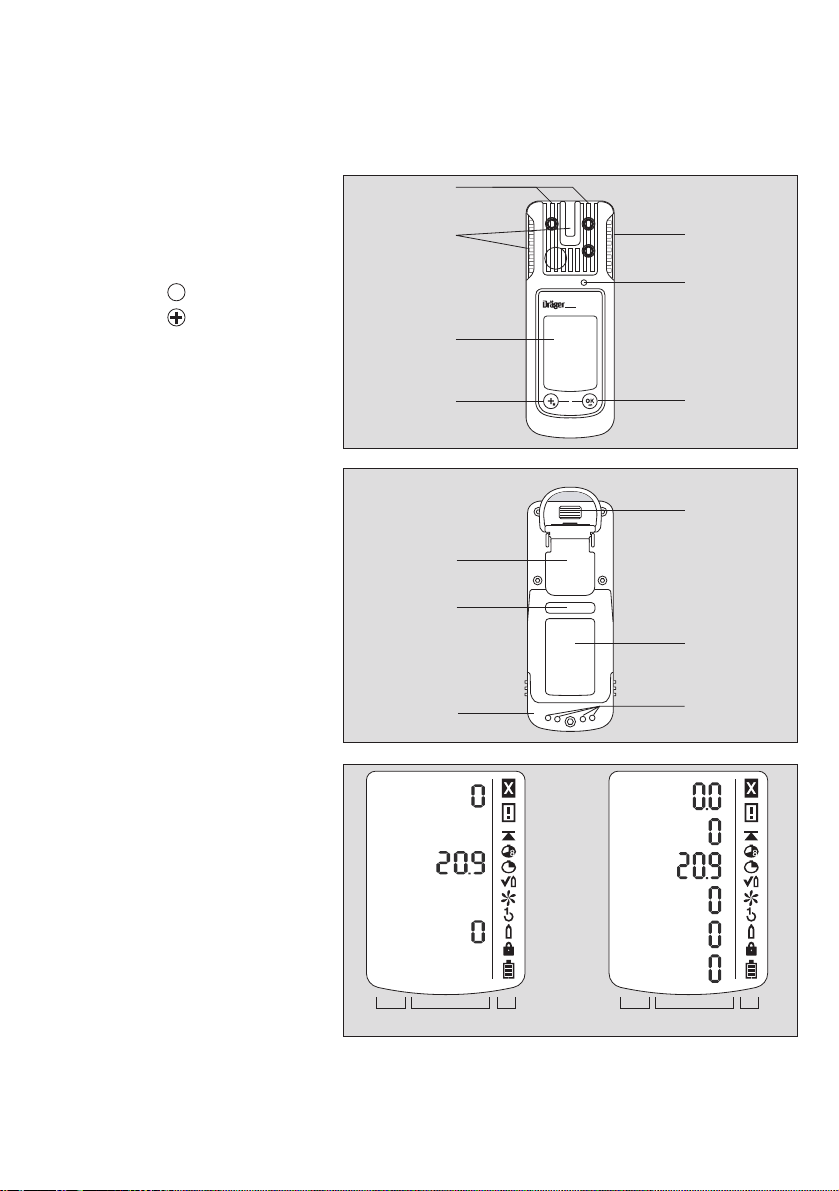
Front panel
1 Gas entry
2 Alarm LED
3 Buzzer
OK
4 key
5 key
6 Display
Rear panel
1 IR interface
2 Fastening clip
3 Type plate
4 Charging contacts
5 Power pack
6 Serial no.
Display
for 1 to 4 measuring
channels:
1 Measured gas
display
2 Measured gas
display with unit
3 Special symbols
for 5 and 6 measuring
channels:
4 Measured gas
display with unit
5 Measured gas
display
6 Special symbols
The following only shows the instrument version with 6 measuring channels.
7
Page 8

Special symbols
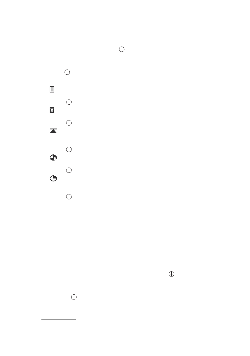
Fault message, refer to page 15
Warning message, refer to page 15
The peak value display for all measuring gases, refer to page 15
The exposure evaluation display (TWA) for measuring gases, e.g., H
refer to page 15
The exposure evaluation display (STEL) for measuring gases, e.g., H
refer to page 15
The instrument is set to function test with gas (bump test),
refer to page 41
The instrument is set to the fresh air calibration function,
refer to page 48
The instrument is set to the 1-button calibration/adjustment function,
refer to page 50
The instrument is set to the single gas calibration function,
refer to page 53
The function for password entry is active, refer to page 18
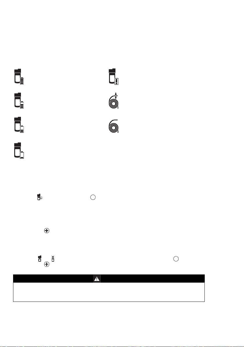
Battery / rechargeable battery 100 % full
Battery / rechargeable battery 2/3 full
Battery / rechargeable battery 1/3 full
Battery / rechargeable battery empty
Marking offset channels:
Feature Reading on the display
ToxicTwins HCN+
CO H
compensation CO+
2
H
offsetting ch4+
2
S and CO,
2
S and CO,
2
8
Page 9
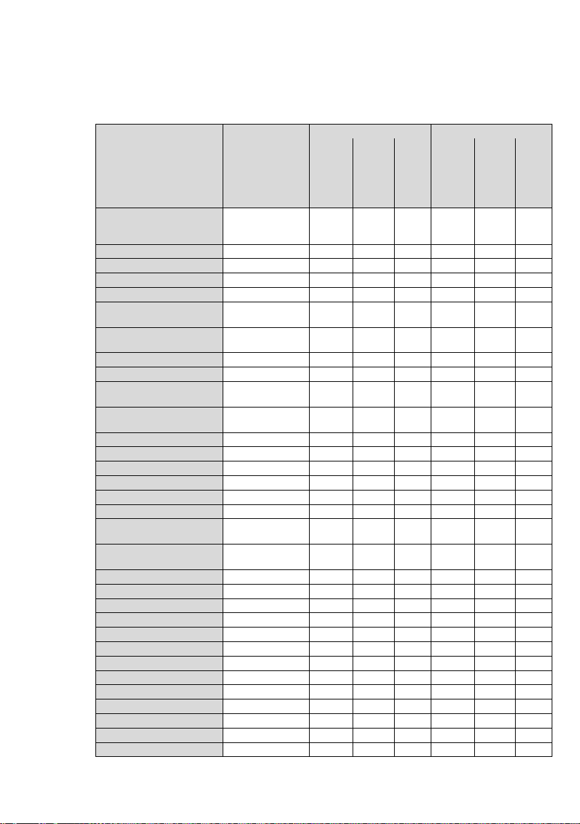
Configuration
Standard gas configuration
DrägerSensor
Measuring
1)
range
Alarm A1
1)
Alarm A2
1)
DUAL IR Ex/CO2:
DUAL IR-Ex [%LEL]
DUAL IR-CO
[vol. %]
2
0 to 100
0 to 5
threshold
20
0.5
can be
acknowledged
self-latching
threshold
Yes
YesNoNo401.0NoNo
can be
acknowledged
Ye s
Ye s
IR-Ex [%LEL] 0 to 100 20 Yes No 40 No Ye s
IR-CO2 [vol. %] 0 to 5 0.5 Ye s No 1.0 No Ye s
XXS O2 [vol. %] 0 to 25 19
XXS O2 100 [vol. %] 0 to 100 18
XXS O2 LS/CO-LC
[vol.-%], [ppm]
XXS O2 / H2S-LC
[vol%], [ppm]
0 to 25 O
0 to 2000 CO
0 to 25 O
0 to 100 H2S
2
2
2)
No Ye s 23 No Ye s
2)
No Ye s 24 No Ye s
19 O
30 CO
19 O
5 H2SNoYes
No
2
Yes
2
YesNo23 O
60 CO
YesNo23 O
10 H2SNoNo
2
2
NoNoYe s
Ye s
Ye s
Ye s
XXS CO [ppm] 0 to 2000 30 Yes No 60 No Ye s
XXS CO LC [ppm] 0 to 2000 30 Ye s No 60 No Yes
XXS CO-LC/H2S-LC
[ppm]
XXS CO-LC/O2 [ppm],
[vol.-%]
0 to 2000 CO
0 to 100 H
0 to 2000 CO
0 to 25 O
2
2
30 CO
5 H
S
30 CO
19 O
S
2
2
Yes
YesNoNo
YesNoNo
Yes
60 CO
10 H
60 CO
23 O
S
2
2
NoNoYe s
Ye s
NoNoYe s
Ye s
XXS CO HC [ppm] 0 to 10,000 600 Ye s No 1.200 No Ye s
XXS CO H2-CP [ppm] 0 to 2,000 30 Ye s No 60 No Ye s
XXS H2 [ppm] 0 to 2,000 200 Ye s No 400 No Ye s
XXS H2S [ppm] 0 to 200 5 Ye s No 10 No Ye s
XXS H2S LC [ppm] 0 to 100 5 Ye s No 10 No Ye s
XXS H2S HC [ppm] 0 to 1,000 10 Ye s No 20 No Ye s
XXS H2S/CO [ppm]
XXS H2S-LC/CO-LC
[ppm]
0 to 200 H2S
0 to 2,000 CO
0 to 100 H2S
0 to 2000 CO
5 H2S
30 CO
5 H2S
30 CO
Yes No
Yes
YesNoNo
10 H2S
60 CO
10 H2S
60 CONoNo
No Ye s
Ye s
Ye s
XXS NO [ppm] 0 to 200 25 Yes No 50 No Ye s
XXS NO2 [ppm] 0 to 50 5 Ye s No 10 No Ye s
XXS SO2 [ppm] 0 to 100 0,5 Ye s No 1 No Ye s
XXS PH3 [ppm] 0 to 20 0.1 Ye s No 0.2 No Ye s
XXS PH3 HC [ppm] 0 to 1,000 5 Yes No 10 No Ye s
XXS HCN [ppm] 0 to 50 1,9 Ye s No 3,8 No Ye s
XXS HCN PC [ppm] 0 to 50 5 Ye s No 10 Ye s No
XXS NH3 [ppm] 0 to 300 20 Ye s No 40 No Ye s
XXS CO2 [vol. %] 0 to 5 0.5 Ye s No 1 No Ye s
XXS Cl2 [ppm] 0 to 20 0.5 Ye s No 1 No Ye s
XXS H2 HC [vol. %] 0 to 4 0.8 Ye s No 1.6 No Ye s
XXS OV [ppm] 0 to 50 10 Ye s No 20 No Ye s
XXS OV A [ppm] 0 to 50 10 Ye s No 20 No Ye s
self-latching
9
Page 10
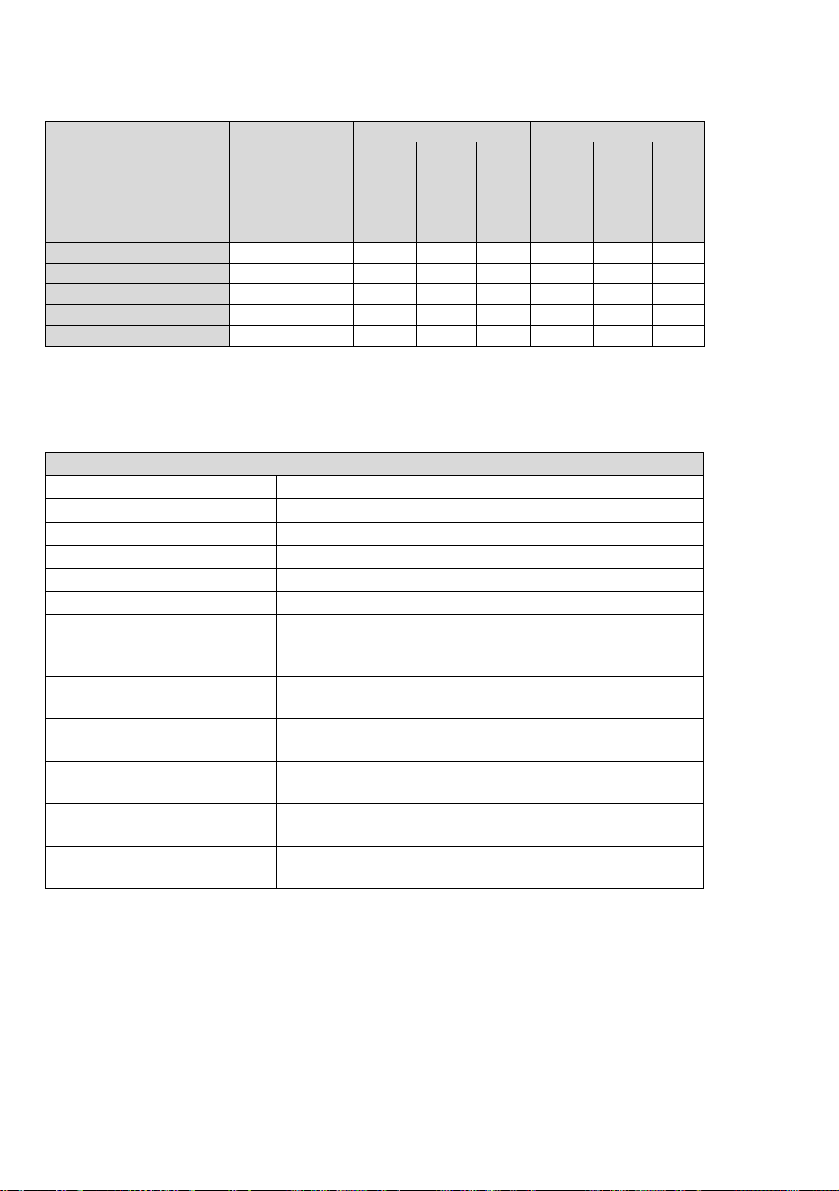
DrägerSensor
Measuring
1)
range
Alarm A1
1)
Alarm A2
1)
threshold
can be
acknowledged
self-latching
threshold
can be
acknowledged
self-latching
XXS Odorant [ppm] 0 to 40 10 Yes No 20 No Ye s
XXS Amine [ppm] 0 to 100 10 Yes No 20 No Ye s
XXS COCI2 [ppm] 0 to 10 0,1 Ye s No 0,2 No Yes
XXS O3 [ppm] 0 to 10 0,1 Ye s No 0,2 Ye s No
XXS NO2 LC [ppm] 0 to 50 0,5 Ye s No 1,0 Ye s No
1) Different settings can be selected to meet customer requirements on delivery. The current setting can
be checked and changed with the Dräger CC Vision software. A version of Dräger CC Vision which can
be used for Dräger X-am 5600 is supplied with the instrument on CD.
2) In the case of O2 A1 is the lower alarm threshold: an alarm is triggered if the value is too low.
Standard instrument configuration
Dräger X-am 5600
Bump test mode
Fresh air calibration 2)
Hydrogen offset
Operating signal
Capture range On
Switch off
LEL factor
ch
4
H
2
STEL
2)
2)
2) 6) 7)
(short-term average)
2) 7) 8)
TWA
(shift average)
Alarm A1
9)
Alarm A1 at O
Alarm A2
1) X-am® is a registered trademark of Dräger.
2) Different settings can be selected by the customer on delivery. The current setting can be
3) The fresh air calibration/zero-point calibration is not supported by the DrägerSensor DUAL IR
4) With activated DrägerSensor XXS H2 HC (68 12 025) and activated Ex-channel of the
5) A periodic short flashing indicates the operating capacity of the instrument. If there is no
6) STEL: average value of an exposure over a short period, generally 15 minutes.
7) Interpretation only if the sensor is designed for this.
8) TWA: shift averages are workplace limit values for generally eight hours per day of exposure for
9) Latching and acknowledgement of alarms A1 and A2 can be configured with the Dräger CC
9)
checked and changed with the Dräger CC Vision software.
CO
, DrägerSensor IR CO2 or the DrägerSensor XXS O3.
2
DrägerSensor DUAL IR Ex/CO2 (68 11 960) or DrägerSensor IR Ex (68 12 180).
operating signal, correct operation cannot be guaranteed.
five days a week during a working life.
Vision PC software.
2)
4)
2) 5)
sensor
2
1)
Extended bump test
3)
On
On
On
blocked at A2
4.4 vol. % (4.4 vol. % corresponds to 100 %LEL)
4.0 vol. % (4.0 vol. % corresponds to 100 %LEL)
STEL function - disabled
Average value duration = 15 minutes
TWA function - disabled
Average value duration = 8 hours
can be acknowledged, non-latching, pre-alarm,
rising flank
9)
cannot be acknowledged, latching, like main alarm,
falling flank
cannot be acknowledged, latching, main alarm,
rising flank
10
Page 11
By activating the H
DrägerSensor XXS H
activated DrägerSensor DUAL IR Ex/CO
IR Ex (6812180) and shown on the display at the position of the IR Ex display.
added signal, the LEL gas concentration of the activated
2
HC (6812025) is added to the LEL gas concentration of the
2
(6811960) or of the activated DrägerSensor
2
NOTICE
Previously set alarm thresholds are preserved so that in the presence of hydrogen
(H2) the alarm of the IR Ex channel could be triggered earlier.
Changing the configuration: see “Configuring the Instrument” on page 24.
WARNING
After a basic initialization has been carried out with the PC software Dräger
CC Vision, individual alarm settings may have been changed.
Selecting or disabling the capture ranges (only applies for the measuring mode):
The capture range is selected in the measuring mode (factory setting) and permanently
disabled in calibration mode.
The CC-Vision PC software can be used to select or disable the capture ranges for the
measuring mode.
11
Page 12
Operation
OK
OK
Before using the instrument for the first time, insert a charged NiMH T4 power pack
or batteries approved by Dräger, see "Changing the batteries" on page 58.
The instrument is now ready for operation.
WARNING:
To reduce the risk of ignition of a flammable or explosive atmosphere, strictly adhere
to the following warning statements:
Only use power pack types ABT 01xx, HBT 00xx or HBT 01xx. See the marking on
the rechargeable battery for permitted rechargeable batteries and the corresponding
temperature class.
Substitution of components may impair intrinsic safety.
Switching on the instrument
Press and hold the key for approx. 3 seconds until the countdown »3.2.1«
shown in the display has elapsed.
— All the display segments, including the visual, audible and vibration alarms, are
activated for a short time.
— The software version is displayed.
— The instrument performs a self test.
— The next sensor which is next due for calibration is displayed with the days
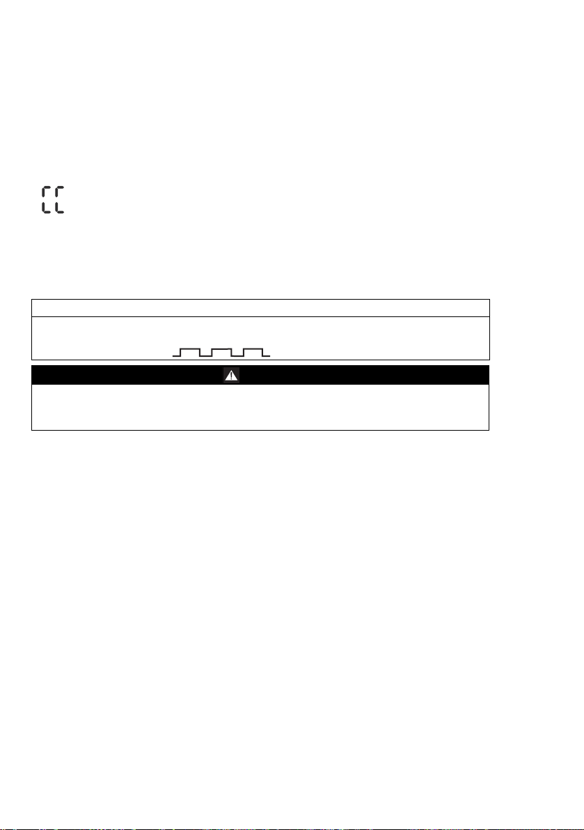
remaining until the next calibration/adjustment, e.g., »ch
— The time until the bump test interval elapses is displayed in days, e.g., »bt2«.
— All A1 and A2 alarm thresholds and if applicable »« (TWA)
for all toxic gases (e. g. H
— During the sensor warm-up phase:
S or CO) are displayed consecutively.
2
— The display for the measured value flashes
— The special symbol »« is displayed.
— No alarms are issued during the warm-up phase.
— The red LEDs flash.
— The gas detector is ready to measure when the measured values no longer flash
and the red LEDs are no longer illuminated. The special symbol »« may continue
to be displayed if corresponding warnings (e.g. not yet ready for calibration) are
active (to view the warnings, see the technical manual).
Press the key to cancel the display of the activation sequence.
%LEL CAL 123 «.
4
1)
and »« (STEL)1)
1) Only when activated in the instrument configuration. Delivery condition: not activated.
12
Page 13
Switching off the instrument
Press and hold the key and key at the same time until the countdown
»3.2.1« shown in the display has elapsed.
— Before the instrument is switched off, the visual, audible and vibration alarms are
activated for a short time.
OK
Before entering the workplace
WARNING
Before any measurements relevant to safety are made, check the adjustment with a
bump test, adjust if necessary and check all alarm elements. If national regulations
apply, a bump test must be performed according to the national regulations. Faulty
adjustment may result in incorrect measuring results, with possible serious
consequences.
WARNING
In an oxygen enriched atmosphere (>21 vol. % O
be guaranteed; remove instrument from the Ex area.
NOTICE
If the gas detector is used for offshore applications, a distance of 5 m to a compass
must be complied with.
Switch on the instrument. The current measured values are shown in the display.
Observe any warning » « or fault messages » «.
The instrument can be operated normally. If the warning message does not go
out automatically during operation, the instrument must be maintained after the
end of use.
), the explosion protection cannot
2
The instrument is not ready to measure and requires maintenance.
— If one of these special symbols is displayed, appropriate measures, refer to page 28
to page 32, must be taken.
Check that the gas inlet opening on the instrument is not covered and/or dirty.
13
Page 14
During operation
— During operation, the measured values for every measured gas are displayed.
— In the event of an alarm, the corresponding displays, including the visual, audible
and vibration alarms, are activated. See section "Identifying Alarms"
— If a measuring range is exceeded or not reached, the following displays are shown
instead of the measured value display:
»« (measuring range exceeded) or
»« (measuring range not reached).
— After the measuring range of the TOX measuring channels has been exceeded
temporarily (up to one hour), checking the measuring channels is not necessary.
— Following an extreme impact load, the display for the Ex- and the CO
range of the IR Sensor must be checked and adjusted with zero gas and span gas
if necessary.
NOTICE
Special states in which there is no measuring operation (quick menu, calibration
menu, warm-up of sensors, password input) are indicated by a visual signal (slow
flashing of the alarm LED ).
WARNING
When using an IR Sensor in the Dräger X-am 5600, the zero point and sensitivity
must be adjusted after an impact load that causes a display other than zero for the
IR sensor when the instrument is at fresh air.
measuring
2
14
Page 15
Calling the Info Mode
OK
OK
OK
OK
OK
OK
OK
In measuring mode, press the key for approx. 3 seconds.
If any warning or fault messages exist, the corresponding information or error codes
are displayed (page 28 to page 35).
Press the key successively for the next display.
The peak values and the exposition values TWA
Warning messages are displayed. Numerical codes of warning messages:
see page 28.
key
Fault messages are displayed. Numerical codes of fault messages:
see page 32.
key
The peak values = the maximum measured values in the case of, e.g., CO,
H
S, ... or the minimum measured values in the case of O2 within the storage
2
interval are displayed
key
The average values of the exposures based on a shift of, e.g., 8 hours (TWA)
of all the active sensors for the exposure evaluation are displayed
key
The short-term values (STEL) = average values of the concentrations over
the average value duration of all the active sensors for the exposure
evaluation are displayed
key
The instrument is in measuring mode again
OK
1)
and STEL1) are displayed.
— If no key is pressed for 10 seconds, the instrument returns automatically to
measuring mode.
Calling the Info-Off Mode
When the instrument is in a deactivated state, press the key.
The name of the gas, measuring unit and measuring range limit value are displayed for
all channels.
Pressing the key again exits the Info Off mode (or via timeout).
1) Only when activated in the instrument configuration. Delivery status: not activated.
15
Page 16
Calling the Quick Menu
— Only the fresh air calibration/zero-point calibration is activated in the quick menu on
delivery. The PC software Dräger CC Vision can be used to activate the bump test
for the quick menu and/or the function for displaying and deleting peak values.
In measuring mode, press the key three times.
If no functions have been activated in the quick menu, the instrument remains in
measuring mode.
— You can select the activated functions of the quick menu by pressing the key.
Press the key to call the selected function.
Possible functions of the quick menu
Press the key to cancel the active function and to switch to measuring mode.
— If no key is pressed for 60 seconds, the instrument returns automatically to
measuring mode.
OK
Function test with gas (bump test), refer to page 41.
Fresh air calibration, refer to page 48.
1)
Delete peak values, refer to page 17.
Display pump information, refer to page 21.
Activate or deactivate pump, refer to page 21.
______________________________________________
1) Fresh air calibration / zero-point calibration is not supported by the DrägerSensor DUAL IR CO2,
the DrägerSensor IR CO2 or the DrägerSensor XXS O3. A zero-point calibration / adjustment of
these sensors can be conducted using the Dräger CC-Vision PC software. To do so, a suitable
zero gas that is free of carbondioxide and ozone (e.g. N
) should be used.
2
16
Page 17
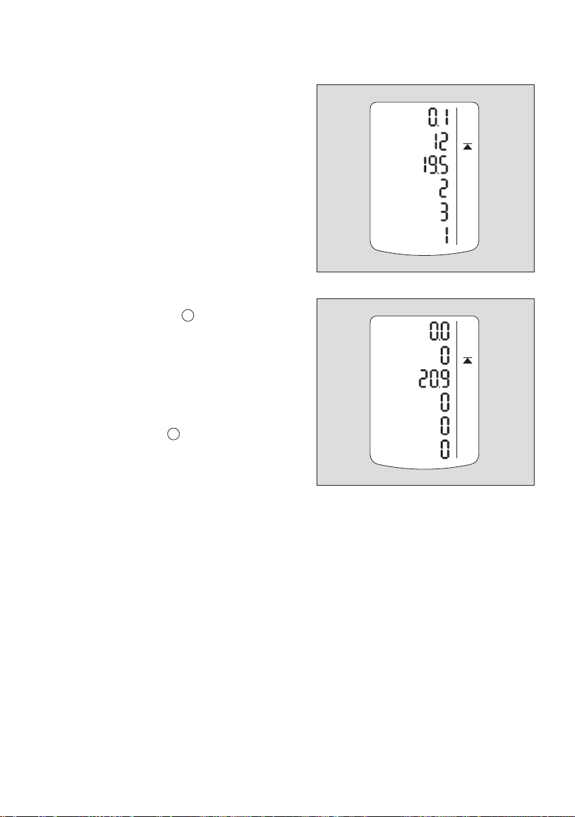
Quick menu "Delete peak
OK
OK
values"
After the function has been selected, the
current peak values are displayed; the
peak values special symbol appears in
the display at the same time.
The peak values can be deleted by
pressing the key for 5 sec. The
adjacent display appears.
Press the key to end the function.
CO
2
Vol %
ch
4
%LEL
2
O
Vol %
CO
ppm
2
S
H
ppm
3
NH
ppm
CO
Vol %
ch
4
%LEL
2
O
Vol %
CO
ppm
2
S
H
ppm
NH
3
ppm
04833072_01_en.eps
2
04933072_01_en.eps
17
Page 18
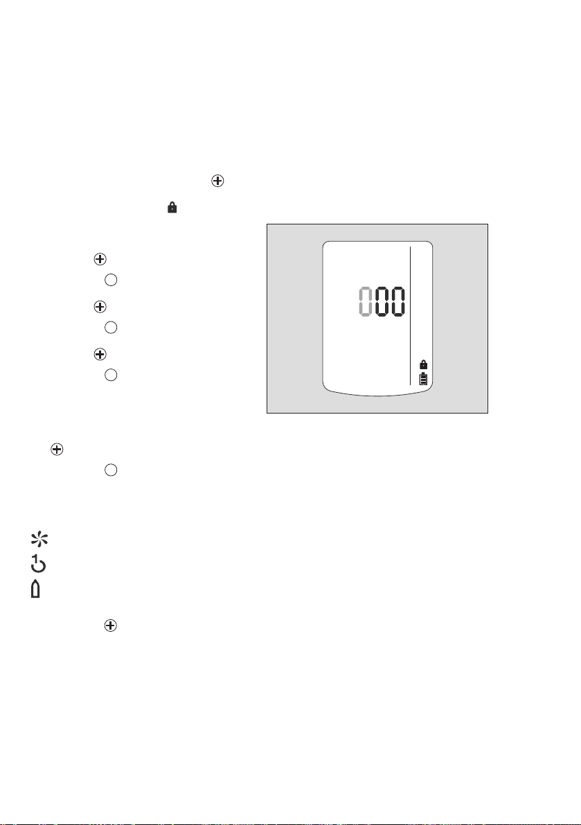
Calling the Calibration Menu
02333072_01.eps
— The calibration menu can only be accessed by entering a password.
Password on delivery: »001«
— The default password on delivery can be changed using the PC software Dräger
CCVision.
In measuring mode, press the key for at least 4 seconds.
— The function for entering the password is selected.
— The special symbol » « (for the "enter password" function) is displayed.
— The display shows »000«, with the
first digit flashing.
Use the key to set the flashing digit.
Press the key, the second digit
starts flashing.
Use the key to set the flashing digit.
Press the key, the third digit starts
flashing.
Use the key to set the flashing digit.
Press the key to confirm the
password once it has been set
completely.
— The calibration menu functions can
now be selected by pressing the
key.
Press the key to call the selected
function.
OK
OK
OK
OK
Calibration menu functions
Fresh air calibration, refer to page 48.
1)
1-button calibration/adjustment, refer to page 50.
Single gas calibration/adjustment, refer to page 53.
Press the key to cancel the active function.
— If no key is pressed for 10 minutes, the instrument automatically returns to
measuring mode.
______________________________________________
1) Fresh air calibration / zero-point calibration is not supported by the DrägerSensor DUAL IR CO2,
the DrägerSensor IR CO
these sensors can be conducted using the Dräger CC-Vision PC software. To do so, a suitable
zero gas that is free of carbondioxide and ozone (e.g. N2) should be used.
or the DrägerSensor XXS O3. A zero-point calibration / adjustment of
2
18
Page 19
Identifying Alarms
An alarm is displayed visually, audibly and through vibration in a specific pattern.
NOTICE
At low temperatures the legibility of the display can be improved by switching on the
backlight.
Concentration pre-alarm A1
The alarm is indicated by an intermittent alarm message:
Display »A1« and measured value alternating: not for O
— The pre-alarm A1 is not self-latching and stops when the concentration has dropped
below the alarm threshold A1.
— In the case of A1 a single tone is audible and the alarm LED flashes.
Acknowledging the pre-alarm:
Press the key. Only the audible alarm and the vibration alarm are switched off.
OK
Concentration main alarm A2
The alarm is indicated by an intermittent alarm message:
Display »A2« and measured value alternating:
In the case of A2 a double tone is audible and the alarm LED flashes
twice.
: »A1« and measured value alternating = oxygen deficiency
For O
2
» A2 « and measured value alternating = oxygen surplus
!
2
WARNING
Danger to life! Leave the area immediately. A main alarm is selflatching and cannot be acknowledged or cancelled.
After leaving the area, if the concentration is less than the alarm threshold A2:
Press the key. The alarm messages are switched off.
OK
WARNING
The measuring range 0 to 100 vol. % CH
mixtures in the measuring range of 0 to 100 %LEL.
is not suitable for monitoring explosive
4
19
Page 20
STEL / TWA exposure alarm
The alarm is indicated by an intermittent alarm message:
Display »A2« and »« (TWA) or » « (STEL) and measured
value alternating:
WARNING
Risk to health! Leave the area immediately.
After this alarm, the deployment of personnel is subject to the relevant national
regulations.
NOTICE
The STEL alarm can be triggered with a maximum delay of one minute.
— STEL and TWA alarms cannot be acknowledged or cancelled.
Switch off the instrument. The values for the exposure evaluation are deleted after
the instrument is switched on again.
Battery pre-alarm
The alarm is indicated by an intermittent alarm message:
Flashing special symbol »« on the right side of the display:
Acknowledging the pre-alarm:
Press the key. Only the audible alarm and the vibration alarm are switched off.
— The battery still lasts approx. 20 minutes after the first battery pre-alarm.
OK
Battery main alarm
The alarm is indicated by an intermittent alarm message:
Flashing special symbol »« on the right side of the display:
The battery main alarm cannot be acknowledged or cancelled:
— The instrument is automatically switched off again after 10 seconds.
— Before the instrument is switched off, the visual, audible and vibration alarms are
activated for a short time.
Instrument alarm
The alarm is indicated by an intermittent alarm message:
Special symbol » « on the right side of the display:
— The instrument or one or several sensor channels are not ready for operation.
— For remedies, refer to page 28 to page 35.
If necessary, commission the Dräger Safety Service Center to eliminate the error.
20
Page 21

Operation with pump
Observe the following when performing measurements using the pump
Perform visual inspection of the probe, if necessary.
Wait for the flushing time to end.
Flush the Dräger sampling hose or Dräger probes prior to each measurement with
the air sample to be measured.
The flushing phase is necessary to minimize or eliminate any effects associated with
the use of a sampling hose or a probe, e.g. memory effects, dead volume.
The duration of the flushing phase depends on factors such as type and concentration
of the gas or vapour to be measured, material, length, diameter and age of the
sampling hose or probe. As a rule of thumb, a typical flushing time of 3 seconds per
metre can be assumed for a sampling hose (factory-new, dry, clean). This flushing time
applies in addition to the sensor response time (see instructions for use of the gas
detector used).
Example:
The flushing time for a 10 m hose is approx. 30 seconds. The sensor response time is
approx. 60 seconds in addition. The overall time before reading the gas detector
therefore is approx. 90 seconds.
The flow alarm is delayed by 10 to 30 seconds, depending on the hose length.
Performing a measurement with Dräger Pump X-am 1/2/5000
Required accessories (see "Accessories" on page 67):
Dräger Pump X-am 1/2/5000
Sampling hose and probes
Commissioning and performing the measurement:
See instructions for use of Dräger Pump X-am 1/2/5000.
21
Page 22
Performing a measurement with the Dräger X-am Pump
OK
Required accessories (see "Accessories" on page 67):
Dräger X-am Pump
Sampling hose and probes
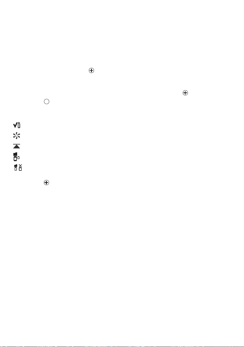
Pump symbols:
Pump battery 100 % charged Warning for pump
(Gas detector can no longer detect
pump.)
Remaining charge of pump
battery: 2/3
Remaining charge of pump
battery: 1/3
Leak test:
Block suction inlet
Leak test:
Release suction inlet
Pump battery discharged
Commissioning and performing the measurement:
See instructions for use of the Dräger X-am Pump.
Viewing pump information:
Open the quick menu (see "Calling the Quick Menu" on page 16).
Select and confirm with the button.
OK
The following pump information will be displayed:
— serial number
— pump runtime (current operation)
— pump battery charge
Press the button to return to measuring mode.
Activating or deactivating the pump:
Open the quick menu (see "Calling the Quick Menu" on page 16).
Select or and activate or deactivate the pump by pressing the button.
Press the button to return to measuring mode.
WARNING
No measurement!
If the pump is connected but deactivated, the gas detector is not ready to measure.
The red LEDs on the gas detector flash.
22
Page 23

WARNING
Impairment of accuracy!
After measuring high concentrations of nonane (>20 %LEL), the accuracy for
measuring nonane is impaired.
The pump is not suitable for long-term measurement of high concentrations of
nonane.
Performing a measurement with a manual pump adapter and rubber ball pump
Required accessories (see "Accessories" on page 67):
Manual pump adapter
Rubber ball pump
Sampling hose
Probes
Commissioning and performing the measurement:
See instructions for use of the accessories used.
23
Page 24

Configuring the Instrument
IR
Calibration cradle (order no. 83 18 752)
with inserted
USB DIRA with USB cable (order no. 83 17 409)
USB DIRA with USB cable
(order no. 83 17 409)
E-Cal module Dräger X-am 125
(order no. 83 18 754)
USB 2.0
USB 2.0
USB 2.0 / COM
01433072_01_en.eps
Dräger
CC-Vision
Dräger
CC-Vision
Dräger
CC-Vision
E-Cal
0
0
0
X-am 5600
To individually configure a instrument with standard configuration, the instrument must
be connected with a PC.
The installed PC software Dräger CC Vision is used for configuration.
Observe the documentation and online help of the software.
24
Page 25

Device settings
NOTICE
Only trained personnel are permitted to make changes to the device configuration.
The following changes can be made to the device parameters for a device:
Designation Field
Password Numeric field (3-figure)
Operating signal LED
Operating signal horn
1)
1)
Yes/ No
Yes/ No
Switch-off mode “Switch off permitted” or
“Switch off prohibited” or
“Switch off prohibited at A2”
Shift length (TWA)
2)
(in minutes) 60 - 14400
(setting for exposure alarm)
Short-term exposure limit (STEL)
minutes)
3) 4)
(in
0 - 15
(setting for exposure alarm)
User ID(12 characters) Alphanumeric field
Switch database on or off On/Off
Overwrite database Yes/No
Database mode Peak/Average
Database interval 1 s / 10 s / 30 s / 1 min / 2 min / 5 min /
10 min / 30 min
Date (date on the PC)
Time (time on the PC)
Warning after expiry of calibration interval Yes/No
Error after expiry of calibration interval Yes/No
Delay until error after expiry of calibration
0 - 10
interval (days)
Automatic detection of Bump Test Station Yes/No
Activate span calibration following
negative bump test
Yes/No (relates only to a device
connected to the Dräger Bump Test
Station)
Bump test mode “extended bump test” or “quick bump test”
or “bump test deactivated”
Warning after expiry of bump test interval Yes/No
Error after expiry of bump test interval
Yes/ No
(if warning activated)
Capture range Yes / No
Remote configuration Yes / No
Bump test interval (days) 1 - 732
25
Page 26

Delay until error after expiry of cal. interval
0-10
(days)
Activate user service life Yes/No
User service life (days)
0 - 999
(if activated)
Running in Yes/No
LEL category “---” or “PTB” or “IEC” or “NIOSH”
(if this is changed, the LEL factor will be
altered to match)
ToxicTwins (HCN) Yes/No
1) At least one of the two operating signals must be switched on.
2) Corresponds to the averaging time and is used to calculate the exposure value TWA.
3) Only evaluated if the sensor is provided for the purpose.
4) Corresponds to the averaging time and is used to calculate the exposure value STEL.
Sensor settings
The following changes can be made to the sensor parameters for the sensors:
Designation Field
Alarm threshold A1 (in measurement unit) 0 - A2
Alarm threshold A2 (in measurement unit) A1 – Measuring range limit value
Type of evaluation
Alarm threshold STEL
(in measurement unit)
Alarm threshold TWA
(in measurement unit)
1)
1)
1)
Inactive, TWA, STEL, TWA+STEL
0 – Measuring range limit value
0 – Measuring range limit value
Calibration interval (days) 0 - 180 (sensor-dependent)
Unit (sensor-dependent) Vol%, %UEG, %LEL, %LIE, ppm, mbar,
ppb, mg/m
3
Gas name: “Ex” (IR-Ex channel only) Yes/No
1) Only evaluated if the sensor is provided for the purpose.
Testing the parameters
In order to ensure that the values have been correctly transferred to the gas measuring
device:
Press the touch button Data from X-am 1/2/5x00
Check parameters.
26
Page 27

Read Database and Display Graphically
IR
Calibration cradle (order no. 83 18 752)
with inserted
USB DIRA with USB cable (order no. 83 17 409)
USB DIRA with USB cable
(order no. 83 17 409)
E-Cal module Dräger X-am 125
(order no. 83 18 754)
USB 2.0
USB 2.0
USB 2.0 / COM
01833072_01_en.eps
Dräger
GasVision
Dräger
GasVision
Dräger
GasVision
E-Cal
0
0
0
X-am 5600
To read the database of the instrument and display it graphically, the instrument must
be connected with a PC.
The installed PC software Dräger GasVision is used for reading and displaying the
database.
Observe the documentation and online help of the software.
27
Page 28

Faults, Cause and Remedy
Fault Cause Remedy
Not possible to switch on
the instrument
Not possible to switch off
the instrument
Display »––« Measuring range calibrated/
To display the numerical codes of the warning and fault messages in the info mode,
page 15.
Warning messages
Discharge the power pack Charge the power pack,
Discharge the alkaline
batteries
The instrument is not set to
measuring mode
The instrument is
configured to "Disable
prohibited"
adjusted incorrectly
Electronics or sensors
defective
page 59.
Insert new alkaline batteries,
page 58.
Select measuring mode.
Configure the instrument to
"Disable allowed" with Dräger
CC Vision.
Recalibrate/adjust the
measuring range, page 47.
Must be repaired by Service.
Special symbol
» « and displayed
numerical code:
152 Customersservicelifecounter
153 Database 90 % full Read the database soon and
154 Database full Read the database and clear
155 Interval for the function test
159 Calibration/adjustment not
28
Cause Remedy
abouttoelapse'
with gas (bump test) elapsed
possible. The menu function
cannot be carried out
because of a message which
is preventing the function
(e.g., sensors in warm-up
phase).
Reset the service life counter
using Dräger CC Vision.
clear memory afterwards.
memory.
Carry out the function test,
page 41.
Determine the message code
via the info menu and switch it
off, if necessary.
Page 29

Special symbol
» « and displayed
numerical code:
351 DrägerSensor XXS EC1 in
352 DrägerSensor XXS EC1 in
353 EC1 concentration has
354 The temperature is too high Operate the instrument within
355 The temperature is too low Operate the instrument within
356 The calibration interval for
357 Alarm setpoint A2 setting is
Cause Remedy
the warm-up phase
the warm-up phase
drifted into the negative
range
DrägerSensor XXS EC1 has
elapsed
greater than 60 %LEL
Wait until warm-up time is
complete.
Wait until warm-up time is
complete.
Carry out fresh air calibration/
zero-point calibration, page 48.
the allowed temperature range.
the allowed temperature range.
Carry out span calibration/
adjustment for DrägerSensor
XXS EC1, page 53.
Set alarm setpoint to less than
60 %LEL.
451 DrägerSensor XXS EC2 in
the warm-up phase
452 DrägerSensor XXS EC2 in
the warm-up phase
453 EC2 concentration has drifted
into the negative range
454 The temperature is too high Operate the instrument within
455 The temperature is too low Operate the instrument within
456 The calibration interval for
DrägerSensor XXS EC2 has
elapsed
457 Alarm setpoint A2 setting is
greater than 60 %LEL
551 DrägerSensor XXS EC3 in
the warm-up phase
552 DrägerSensor XXS EC3 in
the warm-up phase
Wait until warm-up time is
complete.
Wait until warm-up time is
complete.
Carry out fresh air calibration/
adjustment, page 48.
the allowed temperature range.
the allowed temperature range.
Carry out span calibration for
DrägerSensor XXS EC 3,
page 53.
Set alarm setpoint to less than
60 %LEL.
Wait until warm-up time is
complete.
Wait until warm-up time is
complete.
29
Page 30
Special symbol
Cause Remedy
» « and displayed
numerical code:
553 EC3 concentration has drifted
into the negative range
Carry out fresh air calibration/
zero-point calibration, page 48.
554 The temperature is too high Operate the instrument within
the allowed temperature range.
555 The temperature is too low Operate the instrument within
the allowed temperature range.
556 The calibration interval for
DrägerSensor XXS EC3 has
elapsed
557 Alarm setpoint A2 setting is
greater than 60 %LEL
575 Calibration interval for the
compensation channel has
Carry out span calibration for
DrägerSensor XXS EC 3,
page 53.
Set alarm setpoint to less than
60 %LEL.
Adjust the sensitivity of the
compensation channel.
elapsed
576 Calibration required because
of overgassing.
Adjust the sensitivity of the
compensation channel.
651 DrägerSensor XXS EC 4 in
the warm-up phase
652 DrägerSensor XXS EC 4 in
the warm-up phase
653 EC 4 concentration has
drifted into the negative
Wait until warm-up time is
complete.
Wait until warm-up time is
complete.
Carry out fresh air calibration/
zero-point calibration, page 48.
range
654 The temperature is too high Operate the instrument within
the allowed temperature range.
655 The temperature is too low Operate the instrument within
the allowed temperature range.
656 The calibration interval for
DrägerSensor XXS EC 4 has
elapsed
657 Alarm setpoint A2 setting is
greater than 60 %LEL
751 DrägerSensor IR CO
warm-up phase
752 DrägerSensor IR CO
warm-up phase
in the
2
in the
2
Carry out span calibration for
DrägerSensor XXS EC 4,
page 53.
Set alarm setpoint to less than
60 %LEL.
Wait until warm-up time is
complete.
Wait until warm-up time is
complete.
30
Page 31

Special symbol
Cause Remedy
» « and displayed
numerical code:
753 IR CO
concentration has
2
drifted into the negative
Carry out zero-point calibration,
page 48.
range
754 The temperature is too high Operate the instrument within
the allowed temperature range.
755 The temperature is too low Operate the instrument within
the allowed temperature range.
756 The calibration interval for
DrägerSensor IR CO
elapsed
has
2
781 Unstable signal from
DrägerSensor IR CO
2
Carry out span calibration/
adjustment for DrägerSensor IR
, page 53.
CO
2
The warning will reset itself
once the sensor has stabilised.
851 DrägerSensor IR Ex in the
warm-up phase
852 DrägerSensor IR Ex in the
warm-up phase
853 IR Ex concentration has
drifted into the negative range
Wait until warm-up time is
complete.
Wait until warm-up time is
complete.
Carry out fresh air calibration/
zero-point calibration, page 48.
854 The temperature is too high Operate the instrument within
the allowed temperature range.
855 The temperature is too low Operate the instrument within
the allowed temperature range.
856 The calibration interval for
DrägerSensor IR Ex has
elapsed
857 Alarm setpoint A2 setting is
greater than 60 %LEL
881 Unstable signal from
DrägerSensor IR Ex
Carry out span calibration/
adjustment for DrägerSensor IR
Ex, page 53.
Set alarm setpoint to less than
60 %LEL.
The warning will reset itself
once the sensor has stabilised.
31
Page 32

Fault messages
Special symbol
»« and displayed
numerical code:
102 The customers service
103 The instrument is defective The instrument must be
104 Check sum error program
105 The bump test interval has
106 The calibration interval has
107 Bump test error (at least 1
108 The instrument is defective The instrument must be
109 The menu function cannot be
111 Failed alarm element test:
112 Failed alarm element test:
113 Failed alarm element test:
114 Defective parameter check Correct parameters and repeat
115 Device is disabled by X-dock. Activate device with X-dock.
116 Failed software update. The device must be repaired by
117 User parameters not feasible Check configuration of user
118 Flow alarm of X-am Pump Check the gas circuit for
Cause Remedy
lifecounter has elapsed
code
elapsed
elapsed (at least 1 calibration
interval has elapsed)
channel has a bump test
error)
carried out because of an
error.
alarm light.
alarm horn.
Vibration motor.
Reset the service life counter
using Dräger CC Vision.
repaired by Service.
The instrument must be
repaired by Service.
Carry out bump test, page 45.
Carry out span calibration/
adjustment, page 50 or
page 53.
Carry out bump test, page 45 or
carry out span calibration/
adjustment, page 50 or page 53.
repaired by Service.
Determine the error code via the
info menu and switch it off, if
necessary.
Repeat alarm element test with
Dräger X-dock.
Repeat alarm element test with
X-dock.
Repeat alarm element test with
X-dock.
test using X-dock
DrägerService.
parameters and adjust
obstructions and replace filters if
necessary.
32
Page 33

Special symbol
»« and displayed
numerical code:
119 Battery pre-alarm of X-am
120 Battery alarm of X-am Pump Charge pump.
Cause Remedy
Charge pump.
Pump
301 The zero-point calibration/
adjustment of DrägerSensor
XXS EC1 is not valid
302 The span calibration/
adjustment of DrägerSensor
XXS EC1 is not valid
303 The measured value of
DrägerSensor XXS EC 1 is in
the negative range
304 DrägerSensor XXS EC1 is
not inserted or defective
305 Error during the function test
with gas (bump test) of the
DrägerSensor XXS EC1
307 Failed rise time test. Repeat rise time test with
308 User parameters not feasible Check configuration of user
326 Error during warm-up
acceleration DrägerSensor
XXS EC1
401 The zero-point calibration/
adjustment of DrägerSensor
XXS EC2 is not valid
402 The span calibration/
adjustment of DrägerSensor
XXS EC2 is not valid
403 The measured value of
DrägerSensor XXS EC 2 is in
the negative range
404 DrägerSensor XXS EC2 is
not inserted or defective
Carry out fresh air calibration/
zero-point calibration, page 48.
Carry out span calibration,
page 53 or carry out fresh air
calibration, page 48.
Carry out fresh air calibration/
zero-point calibration, page 48.
Check DrägerSensor XXS EC1,
page 62.
Repeat function test. Calibrate
or replace DrägerSensor XXS
EC1, if necessary page 62.
X-dock.
parameters and adjust
Disconnect and reconnect
power pack or replace the
sensor. Sensor must not be
loaded with gas within the first
5minutes.
Carry out fresh air calibration/
zero-point calibration, page 48.
Carry out span calibration/
adjustment, page 53.
Carry out fresh air calibration/
zero-point calibration, page 48.
Check DrägerSensor XXS EC2,
page 62.
33
Page 34

Special symbol
»« and displayed
numerical code:
405 Error during the function test
406 Failed filter test. Repeat filter test with X-dock.
407 Failed rise time test. Repeat rise time test with
408 User parameters not feasible Check configuration of user
426 Error during warm-up
Cause Remedy
with gas (bump test) of
DrägerSensor XXS EC2
acceleration DrägerSensor
XXS EC2
Repeat function test. Calibrate
or replace DrägerSensor XXS
EC2, if necessary page 62.
X-dock.
parameters and adjust
Disconnect and reconnect
power pack or replace the
sensor. Sensor must not be
loaded with gas within the first
5minutes.
501 The zero-point calibration/
adjustment of DrägerSensor
XXS EC3 is not valid
502 The span calibration/
adjustment of DrägerSensor
XXS EC3 is not valid
503 The measured value of
DrägerSensor XXS EC3 is in
the negative range
504 DrägerSensor XXS EC3 is
not inserted or defective
505 Error during the function test
with gas (bump test) of the
DrägerSensor XXS EC3
506 Failed filter test. Repeat filter test with X-dock.
507 Failed rise time test. Repeat rise time test with
508 User parameters not feasible Check configuration of user
525 The span calibration for the
compensation channel is not
valid
Carry out fresh air calibration/
zero-point calibration, page 48.
Carry out span calibration/
adjustment, page 53.
Carry out fresh air calibration/
zero-point calibration, page 48.
Check DrägerSensor XXS EC3,
page 62.
Repeat function test. Calibrate
or replace DrägerSensor XXS
EC3, if necessary page 62.
X-dock.
parameters and adjust
Adjust the sensitivity of the
compensation channel.
34
Page 35

Special symbol
Cause Remedy
»« and displayed
numerical code:
526 Error during warm-up
acceleration DrägerSensor
XXS EC3
Disconnect and reconnect
power pack or replace the
sensor. Sensor must not be
loaded with gas within the first
5minutes.
601 The zero-point calibration/
adjustment of DrägerSensor
Carry out fresh air calibration/
zero-point calibration, page 48.
XXS EC 4 is not valid
602 The span calibration/
adjustment of the
Carry out span calibration/
adjustment, page 53.
DrägerSensor XXS EC 4 is
not valid
603 The measured value of
DrägerSensor XXS EC 4 is in
Carry out fresh air calibration/
zero-point calibration, page 48.
the negative range
604 DrägerSensor XXS EC 4 is
not inserted or defective
605 Error during the function test
with gas (bump test) of
DrägerSensor XXS EC 4
Check DrägerSensor XXS EC
4, page 62.
Repeat function test. Calibrate
or replace DrägerSensor XXS
EC 4, if necessary page 62.
606 Failed filter test. Repeat filter test with X-dock.
607 Failed rise time test. Repeat rise time test with
X-dock.
608 User parameters not feasible Check configuration of user
parameters and adjust
626 Error during warm-up
acceleration DrägerSensor
XXS EC4
Disconnect and reconnect
power pack or replace the
sensor. Sensor must not be
loaded with gas within the first
5minutes.
701 The zero-point calibration/
adjustment of Dräger
Sensors IR CO
is not valid
2
702 The span calibration/
adjustment of Dräger
Sensors IR CO
is not valid
2
Carry out zero-point calibration,
page 48.
Carry out span calibration,
page 53 or carry out fresh air
calibration, page 48.
35
Page 36

Special symbol
Cause Remedy
»« and displayed
numerical code:
703 The measured value of
Dräger Sensors IR CO
the negative range
704 Dräger Sensor IR CO
inserted
2
is not
2
705 Error during the function test
with gas (bump test) of the
Dräger Sensors IR CO
2
Carry out zero-point calibration,
is in
page 48.
Check Dräger Sensor IR CO2,
page 62.
Repeat function test. Calibrate
or replace Dräger Sensor IR
, if necessary, page 62.
CO
2
706 Failed filter test. Repeat filter test with X-dock.
707 Failed rise time test. Repeat rise time test with X-
dock.
708 User parameters not feasible Check configuration of user
parameters and adjust
731 Error in Dräger Sensor IR
CO
2
732 Error in Dräger Sensor IR
CO
2
733 Unstable signal from
DrägerSensor IR CO
2
734 Zero-point calibration of
DrägerSensor IR CO
failed
2
735 Span calibration of
DrägerSensor IR CO
failed
2
Check Dräger Sensor IR CO2,
page 62.
Check Dräger Sensor IR CO2,
page 62.
The error will reset itself once
the sensor has stabilised.
Repeat zero-point calibration.
Repeat span calibration.
801 The zero-point calibration/
adjustment of Dräger Sensor
IR Ex is not valid
802 The zero-point calibration/
adjustment of Dräger Sensor
IR Ex is not valid
803 The measured value of
Dräger Sensors IR Ex is in
the negative range
804 Dräger Sensor IR Ex is not
inserted
805 Error during the function test
with gas (bump test) of the
Dräger Sensors IR Ex
36
Carry out fresh air calibration/
zero-point calibration, page 48.
Carry out span calibration,
page 53 or carry out fresh air
calibration, page 48.
Carry out fresh air calibration/
zero-point calibration, page 48.
Check Dräger Sensor IR Ex,
page 62.
Repeat function test. Calibrate
or replace Dräger Sensor IR Ex,
if necessary, page 62.
Page 37

Special symbol
»« and displayed
numerical code:
806 Failed filter test. Repeat filter test with X-dock.
807 Failed rise time test. Repeat rise time test with X-
808 User parameters not feasible Check configuration of user
831 Error in Dräger Sensor IR Ex Check Dräger Sensor IR Ex,
832 Error in Dräger Sensor IR Ex Check Dräger Sensor IR Ex,
833 Unstable signal from
834 Zero-point calibration of
835 Span calibration of
Cause Remedy
dock.
parameters and adjust
page 62.
page 62.
DrägerSensor IR Ex
DrägerSensor IR Ex failed
DrägerSensor IR Ex failed
The error will reset itself once
the sensor has stabilised.
Repeat zero-point calibration.
Repeat span calibration.
37
Page 38

Maintenance
Maintenance intervals
The instrument should be inspected and maintained by suitably qualified persons
annually. Comparisons:
EN 60079-29-2 – Gas detectors - Selection, installation, use and maintenance of
detectors for flammable gases and oxygen
EN 45544-4 – Electrical apparatus used for the direct detection and direct
concentration measurement of toxic gases and vapours - Part 4: Guide for selection,
installation, use and maintenance
National regulations
Recommended calibration interval for measuring channels O
CO: 6 months.
Recommended calibration interval for the measuring channel IR Ex/CO
, H2S, H2, SO2, NO2 and
2
: 12 months.
2
NOTICE
Calibration interval of other gases: see Instructions for Use for the respective
Dräger sensors.
Depending on instrument configuration:
Replace the alkaline batteries or charge the battery – refer to page 58 to page 59 –
after each use, at the latest after the battery alarm has been triggered or after
2weeks.
Calibrating/adjusting the instrument – page 47.
— In regular intervals, according to the sensors used and the operating conditions. For
sensor-specific calibration data, refer to the Instructions for Use/data sheets of the
Dräger sensors used
1)
.
— Before you carry out safety-related relevant measurements, the zero point and
sensitivity of the instruments should be tested in accordance with national
regulations.
Inspection by suitably qualified persons – every year.
— The inspection intervals must be established in each individual case and shortened
if necessary, depending on technical safety considerations, engineering conditions
and the technical requirements of the equipment.
— We recommend that a service agreement be concluded with Dräger Safety and that
repairs also be carried out by them.
Replace the sensors, page 62 – if necessary, when it is not possible to calibrate/
adjust the sensors anymore.
1) The Instructions for Use/data sheets of the sensors used are supplied with the instrument on CD.
See also attached Instructions for Use and Data Sheets of the sensors used.
The Instructions for Use/data sheets of the sensors used can also be downloaded from the
following Internet address: www.draeger.com
38
Page 39

H2 added signal
WARNING
After activating or deactivating the H
In the case of a manual function test the effect of the H
into account accordingly.
The functionality of the H2 added signal is only supported provided a Dräger
Sensor XXS H
or a Dräger Sensor IR Ex sensor in the Dräger X-am 5600. Both units must be set to
HC is operated in conjunction with a Dräger Sensor DUAL IR Ex/CO2
2
LEL.
An added signal can be activated and deactivated via the Dräger CC-Vision PC
software.
added signal check the set alarm thresholds.
2
WARNING
added signal must be taken
2
If the H
By activating the H
Sensor XXS H2 HC (68 12 025) is added to the LEL gas concentration of the activated
Dräger Sensor DUAL IR Ex/CO
(68 12 180) and shown on the display at the position of the IR Ex display.
added signal feature is activated, ch4+ appears in the measured value display.
2
added signal, the LEL gas concentration of the activated Dräger
2
(68 11 960) or of the activated Dräger Sensor IR Ex
2
NOTICE
Maintain the set alarm thresholds as they are to ensure that in the presence of
hydrogen (H
) the alarm of the IR Ex Channel is triggered earlier if required.
2
NOTICE
A potentially activated H
during a manual calibration, a PC calibration or an automatic Bump Test for the
added signal is automatically temporarily deactivated
2
relevant duration.
39
Page 40

ToxicTwins
When the ToxicTwins feature is activated, the measuring channels of the XXS CO
sensor and the XXS HCN sensor are offset against each other in such a manner that
the device issues an alarm before the respective A1 alarm threshold is reached if both
gases are detected at the same time.
Prerequisites:
— The XXS CO and XXS HCN sensors are installed.
— The ToxicTwins feature is activated (using the Dräger CC-Vision PC software).
If the ToxicTwins feature is activated, HCN+ appears in the measured value display.
CO H2 compensation
Carbon monoxide (CO) and hydrogen (H2) can occur simultaneously in workplaces in
the steel industry, refineries, sewage works, etc. Hydrogen affects the CO signal in
ordinary commercially available sensors, which leads to false alarms. The XXS CO
-CP sensor uses two sensing electrodes. One of these electrodes measures CO and
H
2
, the other one measures only H2. The difference between the two signals is
H
2
calculated, so that only the CO value will be displayed. For example, a hydrogen
concentration of 1000 ppm (2.5 %LEL) will only result in a maximum of 15 ppm CO
being displayed, but the CO alarm will not be triggered.
This feature is automatically available and activated if the XXS CO H
installed. Deactivation is not possible.
Prerequisites:
—XXS CO H
-CP sensor is installed.
2
If this feature is used, CO+ appears in the measured value display.
40
-CP sensor is
2
Page 41

Carry out manual bump test
WARNING
In the case of a manual function test the effect of the H
into account accordingly.
NOTICE
A potentially activated H
manual calibration, a PC calibration or an automatic Bump Test for the relevant duration.
added signal is automatically temporarily deactivated during a
2
Manual implementation without the documentation of results in the instrument memory
Prepare a test gas cylinder, the
volume flow must be 0.5 l/min and the
gas concentration must be higher than
the alarm threshold concentration to
be tested.
Example:
test gas cylinder 68 11 132 = mixed gas
with 50 ppm CO, 15 ppm H
, 2.5 vol. % CH4, 18 vol. % O
%CO
2
S, 2 vol.
2
2
test gas cylinder 68 11 130 = mixed
gas with 50 ppm CO, 15 ppm H
2.5 vol. % CH
, 18 vol. % O
4
S,
2
2
Connect the test gas cylinder with the
calibration cradle (83 18 752).
Vent the test gas into a fume cupboard
or into the open air (with a hose
connected to the second connector of
the calibration cradle).
added signal must be taken
2
0.5 L/min
CO2
Vol%
ch4
%LEL
2
O
Vol%
CO
ppm
2S
H
ppm
3
NH
ppm
0
00533072_01_en.eps
CAUTION
Risk to health! Do not inhale the test gas.
Observe the hazard warnings of the relevant Safety Data Sheets.
Switch on the instrument and insert it into the calibration cradle – press downwards
until it engages.
Open the test gas cylinder valve to let test gas flow over the sensors.
41
Page 42

Wait until the instrument displays the test gas concentration with sufficient tolerance:
e. g.
IR Ex: ±20 %
IR CO2: ±20 %
: ±0.6 vol. %
O
2
TOX: ±20 % 1) of test gas concentration
1) Upon application of the Dräger mixed gas (order no. 68 11 130) the displays should be within
this range.
1)
of test gas concentration
1)
of test gas concentration
1)
If the alarm thresholds are exceeded, the instrument displays the gas concentration
in alternation with »A1« or »A2« depending on the test gas concentration.
Close the test gas cylinder valve and remove the instrument from the calibration
cradle.
— If the concentration has now fallen under the A1 alarm threshold:
Acknowledge the alarm.
If the displays are outside of the above-mentioned ranges:
Calibrating/adjusting the instrument, refer to page 47.
NOTICE
To check the measured value response times, apply t90 test gas to the X-am via the
calibration cradle. Check the results in accordance with the information in the table in
the enclosed supplementary documentation (order no. 90 33 890) until 90 % of the
end display is reached.
NOTICE
After the bump test, the display shows a printer icon even if there is no printer
connected to the bump test station.
42
Page 43

Menu implementation with the documentation of results in the instrument memory
The setting whether the bump test is to be carried out manually or automatically is
made using the PC software Dräger CC Vision.
The "Quick bump test" or the "Extended bump test" is selected using the Dräger CC
Vision PC software.
The "Quick bump test" checks whether the gas concentration has exceeded the Alarm
1 threshold (with oxygen, the check is whether the concentration has fallen below the
Alarm 1 threshold).
In the case of the “Extended bump test”, a check is made as to whether the gas
concentration has reached the set bump test concentration within a tolerance window.
Setting on delivery: Extended bump test.
Prepare a test gas cylinder, the
volume flow must be 0.5 l/min and the
0.5 L/min
gas concentration must be higher than
the alarm threshold concentration to
be tested.
Example:
test gas cylinder 68 11 132 = mixed
gas with 50 ppm CO, 15 ppm H
2vol. %CO
18 vol. % O
, 2.5 vol. % CH4,
2
2
test gas cylinder 68 11 130 = mixed
gas with 50 ppm CO, 15 ppm H
2.5 vol. % CH
, 18 vol. % O
4
Connect the test gas cylinder with the
S,
2
CO2
S,
2
2
Vol%
ch4
%LEL
2
O
Vol%
CO
ppm
2S
H
ppm
3
NH
ppm
0
calibration cradle (83 18 752).
Vent the test gas into a fume cupboard
or into the open air (with a hose
connected to the second connector of
the calibration cradle).
00533072_01_en.eps
WARNING
Risk to health! Do not inhale the test gas.
Observe the hazard warnings of the relevant Safety Data Sheets.
43
Page 44

Switch on the instrument and insert it into the calibration cradle – press downwards
02433072_01_en.eps
CO2
Vol %
O
2
Vol %
ch4
%LEL
CO
ppm
H
2S
ppm
NH
3
ppm
OK
until it engages.
Call the quick menu and select the function test with gas (bump test), page 16.
— The current gas concentration values
and the special symbol » «
(for bump test) flash.
Press the key to start the function
test with gas.
Open the test gas cylinder valve to let
test gas flow over the sensor.
— If gas concentration exceeds the
alarm thresholds A 1 or A 2 the
corresponding alarm will occur.
Exit the function test with gas:
After the preset bump test concentration
is reached or a gas alarm is triggered
(with the "Quick bump test"):
— The display containing the current
gas concentration changes with the
display »OK«.
— The bump test that was carried out is
documented with the result and date
in the instrument memory.
Close the test gas cylinder valve and
remove the instrument from the
CO2
Vol %
4
ch
%LEL
2
O
Vol %
CO
ppm
2S
H
ppm
3
NH
ppm
calibration cradle.
— If the concentration values have now
fallen under the A1 alarm thresholds,
the instrument returns to the
measuring mode.
02533072_01_en.eps
— If the set bump test concentration is not reached within the specified time, the alarm
mode is activated to indicate failure.
44
Page 45

— The fault message » « appears
02633072_01_en.eps
CO2
Vol %
O
2
Vol %
ch4
%LEL
CO
ppm
H
2S
ppm
NH
3
ppm
and » « is displayed instead of
the measured value on the faulty
measuring channel.
In this case, repeat the function test
with gas or calibrate/adjust the
instrument, page 47.
The function test with gas can also be
carried out automatically.
The "Bump Test Station" is required for
this function, refer to page 45.
Automatic implementation with the Bump Test Station
Prerequisite:
The instrument must first be configured for the automatic function test with gas
(bump test) using the PC software Dräger CC Vision.
— Activating the instrument for the automatic function test.
— Adjust the test gas concentration (mixed gas) with the Dräger CC-Vision PC
software if it deviates from the following default values – standard on delivery:
50 ppm CO, 15 ppm H
— Define which measuring channels should participate in the automatic function test.
S, 2.5 vol. % CH4, 18 vol. % O
2
2
All measuring channels participate in the function test by default.
Prepare the Bump Test Station according to the instructions.
Switch on the instrument and insert it into the receptacle of the Bump Test Station
until it engages.
CO2
Vol%
ch4
%UEG
2
O
Vol%
CO
ppm
2S
H
ppm
3
NH
ppm
— The function test with gas is started automatically. The special symbol » «
(for bump test) flashes.
0
03833072_01.eps
45
Page 46

Next:
02533072_01_en.eps
CO2
Vol %
O
2
Vol %
ch
4
%LEL
CO
ppm
H
2S
ppm
NH
3
ppm
02633072_01_en.eps
CO2
Vol %
O
2
Vol %
ch4
%LEL
CO
ppm
H
2S
ppm
NH
3
ppm
— If a gas alarm (Quick bump test) is
triggered and the preset bump test
concentration (Extended bump test)
is reached within the specified time,
the display shows the current gas
concentration, alternating with
»OK«.
Remove the instrument from the
Bump Test Station.
— If the concentration values have now
fallen under the A1 alarm thresholds,
the instrument returns to the
measuring mode.
— An error will be triggered if during the function test no alarm occurs and the current
measured values do not reach the set target concentration (only extended bump
test).
— The fault message » « appears
and » « is displayed instead of
the measured value on the faulty
measuring channel.
In this case, repeat the function test
with gas or calibrate/adjust the
instrument, page 47.
The function test with gas can also be carried out manually, refer to page 41 and
page 43.
The PC software Dräger CC Vision can be used to enable the "Automatic calibration
after incorrect bump test" option.
After the bump test, the display shows a printer icon even if there is no printer
connected to the bump gas station.
NOTICE
46
Page 47

Calibrating/adjusting the instrument
NOTICE
A potentially activated H
during a manual calibration, a PC calibration or an automatic Bump Test for the
relevant duration.
Dräger recommends using the extended bump test for cross calibrations
(Dräger X-dock technical manual).
Calibration may not be possible due to instrument and channel errors.
Allow the sensors to warm up before the calibration!
Warm-up time: refer to the Instructions for Use/data sheets of the Dräger Sensors
installed (on CD).
Calibration interval:
— Observe the relevant specifications in the Instructions for Use/data sheets of the
Dräger Sensors installed.
— For critical applications, observe the recommendations in EN 60079-29-2
EN 45544-4
2)
and national regulations. We recommend that you calibrate the
channels after 6 months.
Risk to health! Do not inhale the test gas.
Observe the hazard warnings of the relevant Safety Data Sheets.
— Improve the zero point accuracy – carry out the fresh air calibration/zero-point
calibration, page 48.
— Set the sensitivity of all sensors to the value of the test gas – carry out the 1-button
calibration, page 50.
— Set the sensitivity of a sensor to the value of the test gas – span calibration/
adjustment, page 53.
added signal is automatically temporarily deactivated
2
NOTICE
WARNING
1)
or
1) EN 60079-29-2 – Guidelines for selection, installation, use and maintenance of instruments for
the detection and measurement of flammable gases and oxygen.
2) EN 45544-4 – Electrical instruments for the direct detection and direct concentration
measurement of toxic gases and vapours – Part 4: Guidelines for selection, installation, use and
maintenance.
47
Page 48

Carrying out the fresh air calibration/zero-point calibration
03133072_01_en.eps
O2
Vol %
ch4
%LEL
CO
ppm
H
2S
ppm
NH
3
ppm
OK
To improve the zero point accuracy, you can carry out a fresh air calibration/zero-point
calibration.
NOTICE
If none of the sensors fitted permits calibration with fresh air (e.g. only O
), fresh air calibration is not offered as a menu function.
IR-CO
2
, only
3
— Calibrate the instrument to fresh air calibration/zero-point calibration, free of
measured gases or other interfering gases.
— All sensors are included in the fresh air calibration/zero-point calibration.
1)
Sensors which have not warmed up or which are faulty prevent a calibration/
adjustment.
In the case of sensors which are in the warm-up phase, the message » 159 « is
displayed with the special symbol » « (for warning message).
In the case of a sensor or instrument error, the message » 109 « is displayed with
the special symbol » « (for a fault message).
The message is cleared after 5 sec. and the function is available again in the menu.
— During the fresh air calibration /zero-point calibration, the zero point of all sensors (with
the exception of the DrägerSensors XXSO
In the case of the DrägerSensor XXS O
, DUAL IR CO2 and IR CO2) is set to 0.
2
, the display is set to 20.9 vol.-%.
2
Switch on the instrument.
Depending on instrument configuration:
Call the quick menu and select the
Fresh Air Calibration/zero-point
calibration function, page 16.
or
Call the calibration menu and select
the Fresh Air Calibration /zero-point
calibration function, page 18.
— The current gas concentration values
flash.
When the measured values have
stabilized:
Press the key to perform the fresh
air calibration/zero-point calibration.
1) Fresh air calibration / zero-point calibration is not supported by the DrägerSensor DUAL IR CO2,
the DrägerSensor IR CO
these sensors can be conducted using the Dräger CC Vision software. To do so, a suitable zero
gas that is free of carbondioxide and ozone (e.g. N2) should be used.
or the DrägerSensor XXS O3. A zero-point calibration / adjustment of
2
48
Page 49

— The display containing the current
03233072_01_en.eps
O2
Vol %
ch
4
%LEL
CO
ppm
H
2S
ppm
NH
3
ppm
03333072_01_en.eps
O2
Vol %
ch4
%LEL
CO
ppm
H
2S
ppm
NH
3
ppm
gas concentration changes with the
display »OK«.
Press the key to confirm the
OK
calibration/adjustment or wait for
approx. 5 seconds.
If a fault occurred during the fresh air
calibration/zero-point calibration:
— The fault message » « appears
and » « is displayed for the
respective sensor instead of the
measured value.
In this case, repeat the fresh air
calibration/zero-point calibration.
NOTICE
Automatic surrogate calibration
If the corresponding gas combination and the sensor are approved to do so, an
automatic surrogate calibration and tests can be performed using the PC software
Dräger CC-Vision
1)
.
A gas for the bump test, for the adjustment and the measured gas can be set in the
gas change wizard in Dräger CC-Vision.
Conversions are performed automatically and no longer need to be made manually.
The settings are also used by the Dräger X-dock.
1) The free of charge PC software Dräger CC-Vision can be downloaded from the following
web address: www.draeger.com/software
49
Page 50

Carrying out 1-button calibration/adjustment
NOTICE
If no sensors are approved for the 1-button adjustment via the PC software Dräger
CC-Vision, the 1-button adjustment menu function will not be available.
— All the sensors which can be calibrated/adjusted are included in the 1-button
calibration.
— In the case of the 1-button calibration,
the sensitivity of all sensors is set to
0,5 L/min
the value of the test gas.
When using the test gas cylinder:
68 11 132 = mixed gas with
50 ppm CO, 15 ppm H
2vol.%CO
18 vol. % O
— When using the test gas cylinder:
, 2.5 vol.-% ch4,
2
.
2
S,
2
68 11 130 = mixed gas with 50 ppm
CO, 15 ppm H
18 vol. % O
If a mixed gas with another
composition is used, the specified
concentration values in the
instrument must be changed to the
target values of the mixed gas used
S, 2.5 vol. % ch4,
2
2
CO2
Vol%
ch4
%LEL
2
O
Vol%
CO
ppm
2S
H
ppm
3
NH
ppm
0
using the PC software Dräger
CC Vision.
Connect the test gas cylinder with the
calibration cradle.
Vent the test gas into a fume cupboard or into the open air (with a hose connected
to the second connector of the calibration cradle).
WARNING
Risk to health!
Do not inhale the test gas.
Observe the hazard warnings of the relevant Safety Data Sheets.
02733072_01en.eps
50
Page 51

Switch on the instrument and insert it into the calibration cradle until it engages.
02833072_01_en.eps
CO2
Vol %
O
2
Vol %
ch4
%LEL
CO
ppm
H
2S
ppm
NH
3
ppm
OK
02933072_01_en.eps
CO2
Vol %
O
2
Vol %
ch
4
%LEL
CO
ppm
H
2S
ppm
NH
3
ppm
Call the calibration menu, enter the password and select the 1-button calibration/
adjustment function, page 18.
Press the key to start the 1-button calibration/adjustment.
OK
Open the test gas cylinder valve to let
test gas flow over the sensor.
— The currently displayed measured
values start to flash.
The flashing stops after a static
measured value has been reached.
— The calibration/adjustment is now
carried out automatically.
— The displayed measured values
change to the values according to the
gas supplied.
— The automatic stability monitoring
can be overridden by pressing the
OK
key. A calibration then takes place
immediately. If it is detected that no
test gas has been applied, the 1button calibration will be aborted. The channels will then indicate » n/a «. If only one
sensor is taking part in the 1-button calibration, a calibration will be performed in
each case when the key is pressed.
When the calibration/adjustment is
completed and the displayed
measured values have stabilized:
— The display containing the current
gas concentration changes with the
display »OK«.
Press the key or wait for 5
OK
seconds to quit the calibration/
adjustment.
— The instrument changes to the
measuring mode
Close the test gas cylinder valve and
remove the instrument from the
calibration cradle.
51
Page 52

If a fault occurred during the 1-button
03033072_01_en.eps
CO2
Vol %
O
2
Vol %
ch4
%LEL
CO
ppm
H
2S
ppm
NH
3
ppm
calibration/adjustment.
— The fault message » « appears
and » « is displayed for the
respective sensor instead of the
measured value.
In this case, repeat the 1-button
calibration/adjustment or carry out a
single gas calibration/adjustment,
refer to page 53.
If necessary, replace the sensor,
page 62.
52
Page 53
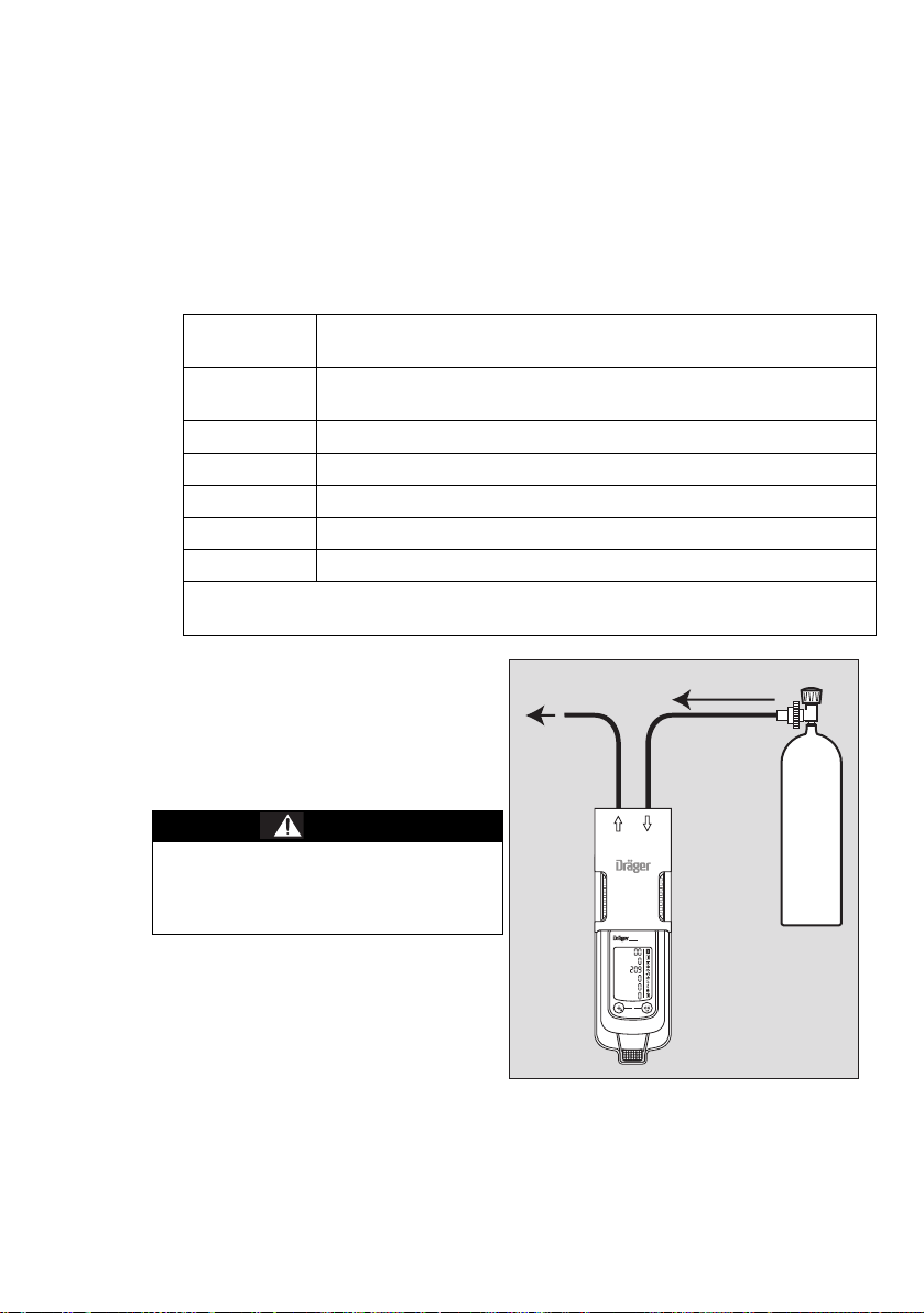
Calibrating/adjusting the sensitivity for an individual measuring channel
0
0,5 L/min
X-am 5000
CO2
Vol%
O
2
Vol%
ch4
%LEL
CO
ppm
H
2S
ppm
NH
3
ppm
— The span calibration/adjustment can be carried out specifically for individual
sensors.
— In the case of the span calibration/adjustment, the sensitivity of the selected sensor
is set to the value of the test gas used.
— Use a standard test gas.
Allowed test gas concentration:
DUAL IR Ex
IR Ex
DUAL IR CO
IR CO
2
O
2
20 to 100 %LEL
2
0.05 to 5 vol.-%
10 to 25 vol.-%
1)2)
/ 5 to 100
2)
1)2)
vol. %
CO: 20 to 999 ppm
H
S: 5 to 99 ppm
2
HC 0,5 to 4,0 vol.-%
H
2
NO
2
5 to 99 ppm
Test gas concentration of other gases:
see Instructions for Use for the respective Dräger sensors.
Connect the test gas cylinder with the
calibration cradle.
Vent the test gas into a fume
cupboard or into the open air (with a
hose connected to the second
connector of the calibration cradle).
WARNING
Risk to health!
Do not inhale the test gas.
Observe the hazard warnings of the
relevant Safety Data Sheets.
_________________________________
1) Depending on the selected data set.
2) Depending on the measuring range and the measuring accuracy.
53
Page 54

Switch on the instrument and insert it
03533072_01_en.eps
ch4
%LEL
OK
OK
OK
into the calibration cradle.
Press the key and keep it pressed
for 5 seconds to call the calibration
menu.
Enter the password with the key
and confirm with the key.
Use the button to select the single
gas calibration/adjustment function
and confirm with the button.
— The display flashes the gas of the first
measuring channel, e.g. » ch
%LEL« (see example 1, page 54).
4
NOTICE
The CO
calibration menu can also be used to adjust the zero point (see example 2, page 56).
Press the key to carry out the calibration/adjustment of this measuring channel,
channel accepts a special setting during the calibration routine, since the
2
OK
or use the key to select another measuring channel (e. g. O
CO - ppm or another toxic sensor).
vol. %, H2S - ppm,
2
There are two examples for the calibration of individual measuring channels below.
Example 1: Span calibration for Dräger Sensor IR Ex.
Press the key to carry out the calibration/adjustment of the selected measuring
OK
channel.
— The calibration gas concentration is displayed
Press the key to confirm the calibration gas concentration or use the key to
OK
change the calibration gas concentration and complete the process by pressing the
key.
— The measurement value flashes.
Open the test gas cylinder valve to let test gas flow over the sensor.
— The displayed, flashing measurement value changes to the value according to the
supplied test gas.
54
Page 55

When the displayed measurement
03633072_01_en.eps
ch4
%LEL
03733072_01_en.eps
ch4
%LEL
value has stabilized:
Press the key to carry out the
OK
calibration.
— The display containing the current
gas concentration changes with the
display »OK«.
Press the key or wait for approx.
OK
5 seconds to quit the calibration/
adjustment of this measuring
channel.
— The next measuring channel appears
for calibration.
— After the calibration/adjustment of the
last measuring channel, the
instrument changes to the measuring
mode.
Close the test gas cylinder valve and remove the instrument from the calibration
cradle.
If a fault occurred during the span
calibration.
— The fault message » « appears
and » « is displayed for the
respective sensor instead of the
measured value.
In this case, repeat the calibration/
adjustment.
If necessary, replace the sensor,
page 62.
55
Page 56

Example 2: Calibration routine for Dräger Sensor DUAL IR CO
OK
Sensor IR CO
Select »CO
— The display shows » 100 vol% N2 « flashing.
2
vol.-% « as measuring channel and confirm with key.
2
and Dräger
2
Zero-point calibration:
Press key to implement the zero-point calibration or use the key to select the
OK
span calibration.
— The calibration gas concentration is displayed.
Press key to confirm the calibration gas concentration 100 vol. % N2 (cannot be
OK
changed).
— The measurement value flashes.
Open the test gas cylinder valve to let test gas flow over the sensor.
— The displayed, flashing measurement value changes to the value according to the
supplied test gas.
When the displayed measurement
value has stabilized:
Press the key to carry out the
OK
calibration.
— The display containing the current
CO2
Vol %
100 Vol% N2
gas concentration changes with the
display »OK«.
Press the key or wait for approx.
OK
5 seconds to quit the zero-point
calibration of this measuring channel.
— The display changes automatically to
span calibration.
Close the test gas cylinder valve and
remove the instrument from the
calibration cradle or, if necessary,
change to test gas for the span
calibration.
— » xx Vol% CO2 « flashes.
Span calibration:
Press the key to carry out the span calibration or press the key for the span
OK
calibration for the next measuring channel.
— The calibration gas concentration is displayed.
Press the key to confirm the calibration gas concentration or use the key to
change the calibration gas concentration and complete by pressing the key.
OK
OK
— The measurement value flashes.
06133072_01_de.eps
Open the test gas cylinder valve to let test gas flow over the sensor.
— The displayed, flashing measurement value changes to the value according to the
supplied test gas.
56
Page 57

When the displayed measurement
06333072_01_de.eps
CO2
Vol %
xx Vol% CO2
06233072_01_de.eps
CO2
Vol %
value has stabilized:
Press the key to carry out the
OK
calibration.
— The display containing the current
gas concentration changes with the
display »OK«.
Press the key or wait for approx.
OK
5 seconds to quit the calibration/
adjustment of this measuring
channel.
— The next measuring channel appears
for calibration.
— After the calibration/adjustment of the
last measuring channel, the
instrument changes to the measuring
mode.
Close the test gas cylinder valve and remove the instrument from the calibration
cradle.
If a fault occurred during the span
calibration.
— The fault message » « appears
and » « is displayed for the
respective sensor instead of the
measured value.
In this case, repeat the calibration/
adjustment.
If necessary, replace the sensor,
page 62.
57
Page 58

Replacing the batteries / rechargeable batteries
1
2a
2b
–
+
–
+
OK
WARNING
Explosion hazard! To reduce the risk of flammable or explosive atmospheres igniting,
it is essential that the warning notices below are observed:
Do not throw used batteries into fire or try to open them by force.
Do not replace or charge batteries in areas at risk of an explosion hazard.
Do not mix new batteries with used batteries, and do not mix batteries from different
manufacturers or of different types.
Remove batteries before maintenance work.
Batteries / rechargeable batteries are part of the Ex approval. Only the following types
may be used:
— Alkaline batteries – T3 – (not rechargeable!)
Panasonic LR6 Powerline
Varta Type 4106
Varta Type 4006
— Alkaline batteries – T4 – (not rechargeable!)
Duracell Procell MN1500
— NiMH rechargeable batteries – T3 – (rechargeable)
GP 180AAHC
1) Not subject to BVS10 ATEX E 080X and PFG 10 G 001X performance approval.
Switching off the instrument:
Press and hold the key and the
key at the same time.
1 Loosen the screw (2.0 mm hexagon
socket) on the power pack and
remove the power pack.
2a For the battery holder
(order no. 83 22 237):
Danger of explosion!
The Dräger X-am 5600 must only be
operated with battery holder ABT 0100
(X-am 5600), identified with a silver
sticker.
Replace alkaline batteries or NiMH
rechargeable batteries. Ensure
correct polarity.
2b Completely replace the power pack T4/T4 HC (with sealed rechargeable batteries,
order no. 83 18 704/83 22 244).
Insert the power pack into the instrument and tighten the screw, the instrument
switches on automatically.
1)
(power one) oder
1)
(industrial)
1)
, Duracell Plus Power MN1500
1)
(1800) max. 40 °C ambient temperature.
WARNING
1)
After replacing the power pack T4/T4 HC, it is recommended that a complete charging
is carried out.
58
Page 59

After the batteries have been replaced:
— The settings and data are stored when the battery is replaced. The sensors warm
up again.
Charging the rechargeable batteries
WARNING
Explosion hazard! To reduce the risk of flammable or explosive atmospheres igniting,
it is essential that the warning notices below are observed:
Do not charge underground or in explosion-hazard areas! Danger of explosion!
The chargers are not designed in accordance with the regulations for firedamp and
explosion protection.
Charge the type HBT 0000 or HBT 0100 power pack using the relevant Dräger
charger. Charge NiMH rechargeable batteries for battery holder ABT 0100 in
accordance with the manufacturer's specifications. Ambient temperature during the
charge process: 0 to +40 °C. See marking on power pack for approved batteries and
related temperature class.
Even if the instrument is not used, we recommend that you store the instrument in the
charger (Charging module X-am 1/2/5000, order no. 83 18 639)!
To maintain the lifetime of the batteries, charging is temperature controlled and only
performed in a temperature range of 5 to 35 °C.
When this temperature range is left, the charging process is automatically interrupted
and automatically continued after the temperature range has been reached again.
The charging time is typically 4 hours.
A new NiMH power pack reaches its full capacity after three complete charging/
discharging cycles. Never store the instrument for extended periods without being
connected to a power source (maximum of 2 months) because the internal buffer
battery will drain.
Charging with the multiple charging station
— A maximum of 20 instruments can be charged at the same time on the power pack
(order no. 83 18 805) of the multiple charging station.
When attaching the charging modules, disconnect the power pack from the mains
supply!
59
Page 60

Attaching charging modules
0
2
1
0
2
1
0
2
1
1
CO2
Vol%
ch
4
%LEL
O
2
Vol%
CO
ppm
H
2S
ppm
NH
3
ppm
CO2
Vol%
ch
4
%LEL
O
2
Vol%
CO
ppm
H
2S
ppm
NH
3
ppm
CO2
Vol%
ch
4
%LEL
O
2
Vol%
CO
ppm
H
2S
ppm
NH
3
ppm
X-am 5600 X-am 5600 X-am 5600
1 Turn the slots of the interlock into a horizontal position by using a screwdriver or
coin.
2 Insert the projecting tongue of the charging module (at the same time, current entry)
until it engages.
1 Close the interlock with a quarter turn (slot is positioned vertically).
Attach additional charging modules in the same way.
— Always connect or disconnect the charging modules individually and not in groups
in order to prevent the charging station from becoming damaged. During
transportation, the power pack and the charging modules should also always be
handled individually and without inserted instruments.
Position the instrument on an even and level surface.
Connecting the power pack to the
mains.
1 The green "Mains" LED lights.
Insert the instrument into the charging
module.
2 Display LED on the charger:
Charge
Fault
Full
If a fault occurs:
Remove the instrument from the
13 2
X-am 5600
CO2
Vol%
CH
4
%LEL
O
2
Vol%
CO
ppm
H
2S
ppm
NH
3
ppm
0
charging module and insert it again.
If the fault still occurs, have the charging
module repaired.
It takes approx. 4 hours to fully charge an
empty rechargeable battery.
A short circuit of the charging contacts in the charging modules, e.g., by metallic
objects that have fallen in, does not result in damage to the charging station. It should,
however, be avoided due to possible heating hazards and incorrect displays on the
charging module.
00833072_01_en.eps
60
Page 61

In the event of a short circuit or if the power pack is overloaded:
00933072_01_en.eps
83 16 994 (100 ... 240 V)
or
83 15 635 (100 ... 240 V)
83 17 754
0
CO2
Vol%
CH
4
%LEL
O
2
Vol%
CO
ppm
H
2S
ppm
NH
3
ppm
X-am 5600
3 The red "Overload" LED lights, and an audible alarm sounds.
— After the fault has been corrected, the alarm is switched off automatically and the
charging process is restarted.
— In the event of a power failure, the instruments already charged will be protected
from discharging.
Charging with charging module and plug-in power pack or vehicle charging adapter
— When using the power pack (order no. 83 16 994), up to 5 instruments can be
charged at the same time, with power pack (order no. 83 15 635) up to 2 instruments.
— The power pack contained in the rechargeable battery and charging set (order
no. 83 18 785) is suitable for charging an instrument.
— When using the vehicle charging adapter (order no. 83 17 754) it is recommended
that you supply every charging module separately.
The charging process is carried out analogue to charging with the multiple charging
station.
61
Page 62

Replacing the Sensors
IR
Calibration cradle (order no. 83 18 752)
with inserted
USB DIRA with USB cable (order no. 83 17 409)
USB DIRA with USB cable
(order no. 83 17 409)
E-Cal module Dräger X-am 125
(order no. 83 18 754)
USB 2.0
USB 2.0
USB 2.0 / COM
01433072_01_en.eps
Dräger
CC-Vision
Dräger
CC-Vision
Dräger
CC-Vision
E-Cal
0
0
0
X-am 5600
CAUTION
Damage to components!
There are components in the instrument that are sensitive to electric charge. Before
opening the instrument to replace the sensor, ensure that the person performing the
work is earthed to avoid damage to the device. Earthing can be safely ensured, e. g.
via an ESD workstation (electrostatic discharge).
NOTICE
To open the instrument, unfasten the casing screws using a screwdriver (Torx T6).
To replace the sensors of the instrument, connect the instrument with a PC.
Replace the sensors using the PC program Dräger CC Vision.
With each replacement of the DrägerSensors DUAL IR Ex/CO
the foam ring located above the sensor should also be exchanged.
, IR Ex or IR CO2,
2
62
Page 63

Next:
Carry out a fresh air calibration/zero-point calibration, page 48.
and then:
Calibrate/adjust the sensitivity:
either
carry out 1-button calibration/adjustment, page 50
or
calibrate/adjust the sensitivity, page 53.
Disposing of electrochemical sensors
WARNING
Do not throw into fire,
Do not force open. Acid burn risk!
Sensors of type XXS O
and XXS NO2 LC contain small quantities of nanomaterials.
3
Like batteries, only dispose of as special waste,
in accordance with local waste disposal regulations. Further information can be
obtained from the relevant local authority and from appropriate waste disposal
companies.
Disposing of infrared sensors
The DrägerSensors DUAL IR Ex/CO
electronic waste.
In accordance with EU Directive 2002/96/EC, this product must not be
disposed of as household waste. This is indicated by with the adjacent icon.
You can return this product to Dräger free of charge. For information please
contact the national marketing organisations and Dräger.
, IR Ex and IR CO2 should be disposed of as
2
63
Page 64

Disposal
Cleaning
The instrument does not need any special care.
Dirt and deposits can be removed from the instrument by washing it with cold water.
A sponge can be used for wiping if necessary.
NOTICE
Abrasive cleaning implements (brushes etc.), cleaning agents and cleaning solvents
can destroy the dust and water filters.
Carefully dab dry the instrument using a cloth.
Storage
Dräger recommends storing the instrument in the charger module (order no.
83 18 639).
Dräger recommends checking the charge of the power supply at least every
three weeks if the instrument is not stored in the charger module.
Disposal
64
This product must not be disposed of as municipal waste. This is indicated by
the adjacent icon. You can return this product to Dräger free of charge. For
information please contact the national sales organisations and Dräger.
Batteries and rechargeable batteries must not be disposed of as municipal
waste. This is indicated by the adjacent icon. Collect and dispose of batteries
and rechargeable batteries at battery collection centres, in accordance with
applicable regulations.
Page 65

Technical Data
Ambient conditions:
during operation and storage Temperature class T4 (–20 to +50 °C):
Temperature range over a short
period (ATEX & IECEx only)
Air pressure 700 to 1300 hPa
Humidity 10 to 90 % (up to 95 % short-term) rel. hum.
Storage time
X-am 5600
Sensors
Instrument data
Position of use any
Protection class IP 67 for instruments with sensors
Alarm volume Typically 90 dB (A) in 30 cm distance
Operation time
Alkaline battery/NiMHy
rechargeable batteries
(battery holder ABT 0100
(X-am 5600))
- NiMH rechargeable batteries
T4 (HBT 0000)
T4 HC (HBT 0100)
Dimensions approx. 130 mm x 48 mm x 44 mm (H x W x D)
Weight approx. 220 g to 250 g
Refresh interval for display and
signals
1) Not part of the BVS 10 ATEX E 080 X and PFG 10 G 001 X technical suitability tests.
NiMH power packs type: HBT 0000, HBT 0100
Power pack type: ABT 0100
with alkaline single cell type:
Duracell Procell MN 1500
Duracell Plus Power MN 1500
1)
,
1)
Temperature class T3 (–20 to +40 °C):
Power pack type: ABT 0100
with NiMH single cell type: GP 180AAHC
with alkaline single cell type:
Panasonic LR6 Powerline
Temperature class T3 (0 to +40 °C):
Power pack type: ABT 0100
with alkaline single cell type: Varta 4006
Varta 4106
–40 to +50 °C
1)
Maximum of 15 minutes with NiMH power pack T4
:
(HBT 0000) or T4 HC (HBT 0100)
1)
Prerequisite: storage of the instrument at room
temperature (+20 °C) for at least 60 minutes in
advance.
1 year
1 year
Typically 9 hours under normal conditions
Typically 9 hours under normal conditions
Typically 10,5 hours under normal conditions
1s
1)
Disposal
1)
,
65
Page 66

Disposal
Order List
Name and description Order no.
Dräger X-am 5600
Unlimited multi gas detector for 1 to 6 gases with
replaceable sensors.
Dräger X-am 5600 ATEX, IECEx
With selectable special calibration.
With default alarm thresholds that can be adjusted
specifically for each country.
Dräger X-am 5600 Basic ATEX, IECEx 83 21 373
Dräger X-am 5600 Basic CSA C US 83 22 930
Power supply units:
NiMH power pack T4 83 18 704
NiMH power pack HBT 0100 T4 HC (X-am 5600) 83 22 244
Battery holder ABT 0100 (X-am 5600),
1)
(without alkaline batteries)
Alkaline batteries T3 (2x)
Alkaline batteries T4 (2x)
1)
1)
Battery and charger set (includes NiMH power pack T4,
charger module for Dräger X-am 1/2/5000 and plug-in
power supply unit)
HC battery and charger set (X-am 5600)
(includes NiMH power pack HBT 0100 T4 HC,
charger module for Dräger X-am 1/2/5000 and plug-in
power supply unit)
83 21 050
83 22 237
83 22 239
83 22 240
83 18 785
83 22 785
Chargers:
Charging adapter for Dräger X-am 1/2/5000 83 26 101
Charger module for Dräger X-am 1/2/5000 83 18 639
Power supply unit with cable (worldwide)
83 15 805
for max. 20 Dräger X-am 1/2/5000 charger modules
Plug-in power supply unit (worldwide)
83 16 994
for max. 5 Dräger X-am 1/2/5000 charger modules
Plug-in power supply unit (worldwide)
83 15 635
for max. 2 Dräger X-am 1/2/5000 charger modules
Vehicle connection, 12 V/24 V
45 30 057
for Dräger X-am 1/2/5000 charger module
Vehicle mount
83 18 779
for 1 Dräger X-am 1/2/5000 charger module
1) Not part of the BVS10 ATEX E 080X and PFG 10 G 001X technical suitability test.
66
Page 67

Disposal
Name and description Order no.
Accessories
The accessories are not part of BVS10 ATEX E 080X and PFG 10 G 001X technical
suitability tests.
Pump accessories:
Dräger Pump X-am 1/2/5000 83 19 400
Case for Dräger Pump X-am 1/2/5000 83 19 385
Dräger X-am Pump 83 27 100
Case for Dräger X-am Pump 83 27 104
USB power supply unit (for Dräger X-am Pump) 83 27 102
USB cable (for Dräger X-am Pump) 83 24 992
Rubber ball pump 68 01 933
Manual pump adapter 83 19 195
Filter set for X-am 1/2/5000 83 19 364
Extension hoses and probes (excerpt):
Measuring probe1), 0.5 m 64 08 238
Measuring probe1), 1.5 m 64 08 239
Telescopic probe1), plug-in 68 01 954
Telescopic probe1) 100 with accessories 83 16 530
Telescopic probe1) 150 stainless steel 83 16 533
Bar probe1) 90 83 16 532
Floating probe with accessories
(transparent)
Fluoroelastomer hose
(5 mm), sold by the metre, specify length when ordering
Hose (not suitable for H2S)
CR-NR (rubber, 5 mm), sold by the metre, specify length
when ordering
3 mm tube connection set
2)
5 mm tube connection set 83 27 642
Floating probe (3 mm), EPP, 3 m hose
Floating probe (3 mm), EPP, 10 m hose
Fluoroelastomer hose (3 mm) incl. adapter, 5 m
Fluoroelastomer hose (3 mm) incl. adapter, 10 m
Fluoroelastomer hose (3 mm) incl. adapter, 20 m
2)
2)
2)
2)
2)
Fluoroelastomer hose3) (3 mm), sold by the metre,
specify length when ordering
83 18 371
12 03 150
11 80 681
83 27 641
83 25 831
83 25 832
83 25 705
83 25 706
83 25 707
83 25 837
67
Page 68

Disposal
Name and description Order no.
Hose (3 mm), PVC, sold by the metre,
83 25 838
specify length when ordering
Hose (rubber, 3 mm), CR-NR, sold by the metre,
83 25 839
specify length when ordering
Accessories for recording the measured values and for
configuration:
Dräger CC-Vision (free full version available at
www.draeger.com/software)
Dräger GasVision licence key
83 25 646
(to upgrade from trial version to full version)
USB DIRA with USB cable (USB infrared adapter for
83 17 409
communication between Dräger X-am 1/2/5000 and PC)
Calibration accessories:
Dräger X-dock, e.g. X-dock 5300 X-am 125 83 21 880
Bump test station, incl. mixed-gas cylinder 83 19 130
E-Cal module for Dräger X-am 1/2/5000 83 18 754
Calibration cradle for Dräger X-am 1/2/5000 83 18 752
Mixed-gas cylinder
15 ppm H
S, 50 ppm CO, 2.5 vol.% CH4, 18 vol.% O2
2
Mixed-gas cylinder
15 ppm H
18 vol.% O
S, 50 ppm CO, 2 vol.% CO2, 2.5 vol.% CH4,
2
2
68 11 130
68 11 132
Test gas cylinder, propane, 0.9 vol.% C3H8 in air 68 11 118
Test gas cylinder, hydrogen, 2 vol.% H2 in air 68 10 388
On-demand controller 83 16 556
Standard controller 68 10 397
Other accessories:
Protective sleeve for Dräger X-am 1/2/5X00 83 21 506
Carrying bag 83 18 755
68
Page 69

Disposal
Name and description Order no.
Spare parts
DrägerSensor DUAL IR Ex/CO
2
DrägerSensor IR Ex 68 12 180
DrägerSensor IR CO
DrägerSensor XXS O2, 0 to 25 vol.%
2
4)
DrägerSensor XXS O2 100, 0 to 100 vol.% 68 12 385
DrägerSensor XXS CO, 0 to 2000 ppm
DrägerSensor XXS H2S, 0 to 200 ppm
DrägerSensor XXS NO2, 0 to 500 ppm
DrägerSensor XXS SO2, 0 to 100 ppm
DrägerSensor XXS CO-LC, 0 to 2000 ppm
5)
2)
2)
2)
2)
Other DrägerSensors upon request
1) The filter set for X-am 1/2/5000 (order no. 83 19 364) includes a 5 mm tube connection set to connect
the probe to the pump.
2) This accessory is optimised for the Dräger X-am Pump (market launch in 2017) (for hoses with 3 mm
inner diameter).
3) 3 mm tube connection set (order no. 83 27 641) required.
4) Expected sensor life time: O2, CO and H2S >5 years.
5) Not part of the BVS10 ATEX E 080X and PFG 10 G 001X technical suitability test.
6) Data sheets for all sensors that may be used with the device can be downloaded from the product
page of the X-am 5600 on the following website: www.draeger.com.
68 11 960
68 12 190
68 10 881
68 10 882
68 10 883
68 10 884
68 10 885
68 13 210
6)
69
Page 70

Page 71

Page 72

Dräger Safety AG & Co. KGaA
Revalstraße 1
D-23560 Lübeck
Germany
Phone +49 451 8 82- 0
Fax +49 451 8 82- 20 80
www.draeger.com
90 33 072 - TH 4638.220 en
© Dräger Safety AG & Co. KGaA
Edition 14 - January 2018
(Edition 01 - September 2009)
Subject to alteration
 Loading...