


Technical Documentation IPM
Savina 300
Intensive Care Ventilator
Warning
All servicing and/or test procedures on the device require detailed knowledge of this documentation. Use of the device requires detailed knowledge and observance of the relevant Instructions for Use.

– This page has been intentionally left blank –
<![if ! IE]><![endif]>No.1309-0000001227_Publication
2 |
Savina 300 |

|
Table of contents |
Table of contents |
|
General |
5 |
General notes . . . . . . . . . . . . . . . . . . . . . . . . . . . . . . . . . . . . . . . . . . . . . . . . . . . . . . . |
. . . . . . . 6 |
Function descriptions |
9 |
Block diagram and functional principle . . . . . . . . . . . . . . . . . . . . . . . . . . . . . . . . . . . . |
. . . . . . . 10 |
Electronic assembly . . . . . . . . . . . . . . . . . . . . . . . . . . . . . . . . . . . . . . . . . . . . . . . . . . . |
. . . . . . 12 |
Control panel with TFT colour display . . . . . . . . . . . . . . . . . . . . . . . . . . . . . . . . . . . . . |
. . . . . . 18 |
Pneumatic assembly. . . . . . . . . . . . . . . . . . . . . . . . . . . . . . . . . . . . . . . . . . . . . . . . . . . |
. . . . . . 20 |
Maintenance instructions |
31 |
Disassembling/assembling the device . . . . . . . . . . . . . . . . . . . . . . . . . . . . . . . . . . . . . |
. . . . . . 32 |
Replacing the microfilter . . . . . . . . . . . . . . . . . . . . . . . . . . . . . . . . . . . . . . . . . . . . . . . . |
. . . . . . 38 |
Replacing the dust filters . . . . . . . . . . . . . . . . . . . . . . . . . . . . . . . . . . . . . . . . . . . . . . . |
. . . . . . 40 |
Replacing the O2 sensors . . . . . . . . . . . . . . . . . . . . . . . . . . . . . . . . . . . . . . . . . . . . . . |
. . . . . . 42 |
Replacing the diaphragm of the expiratory valve . . . . . . . . . . . . . . . . . . . . . . . . . . . . . |
. . . . . . 47 |
Replacing the internal batteries . . . . . . . . . . . . . . . . . . . . . . . . . . . . . . . . . . . . . . . . . . |
. . . . . . 50 |
Replacing the external batteries . . . . . . . . . . . . . . . . . . . . . . . . . . . . . . . . . . . . . . . . . . |
. . . . . . 54 |
Replacing the consumables in the O2 gas inlet . . . . . . . . . . . . . . . . . . . . . . . . . . . . . . |
. . . . . . 65 |
Annex |
71 |
<![endif]>No.1309_0000001227_Publication
Savina 300 |
3 |

– This page has been intentionally left blank –
<![if ! IE]><![endif]>No.1309-0000001227_Publication
4 |
Savina 300 |

General
This chapter contains general notes and definitions that are important for the use of this documentation.
General notes .................................................................................................................................... |
6 |
<![endif]>No.1309_0000001227_Publication
Savina 300 |
5 |

General
General notes
General notes
Notes on use
Copyright and other protected rights
Read through the following notes thoroughly before applying this documentation.
Dräger reserves the right to make changes to the device and/or to this documentation without prior notice. This documentation is intended solely as an information resource for experts.
The content of this documentation, in particular its design, text, software, technical drawings, configurations, graphics, images, data and their selection and its composition and any amendments to it ("content") are protected by copyright. The content must not (in whole or in part) be modified, copied, distributed, reproduced, republished, displayed, transmitted or sold without the prior written consent of Dräger.
Definitions
WARNING!
A WARNING statement provides important information about a potentially hazardous situation which, if not avoided, could result in death or serious injury.
CAUTION
A CAUTION statement provides important information about a potentially hazardous situation which, if not avoided, may result in minor or moderate injury to the user or patient or in damage to the medical device or other property.
NOTE
A NOTE provides additional information intended to avoid inconvenience during operation and/or servicing.
Inspection |
= Identification of actual condition |
Maintenance |
= Measures to maintain the speci- |
|
fied condition |
Repair |
= Measures to restore specified |
|
condition |
Servicing |
= Inspection, maintenance, repair |
<![endif]>No.1309_0000001227_Publication
6 |
Savina 300 |

<![endif]>No.1309_0000001227_Publication
General
General notes
General safety precautions Read through each section thoroughly before beginning servicing. Always use the correct tools and the specified test equipment. Otherwise the device may not work correctly or may be damaged.
WARNING!
Improper servicing
If the medical product is not properly serviced, the safety of the patient and/or the operator may be put at risk.
–Have the medical product checked and maintained on a regular basis by appropriately qualified experts, otherwise the proper functioning of the device may be compromised.
–Have repairs to the medical product carried out only by personnel who have undergone product-specific Dräger training.
NOTE
Dräger recommends entering into a service contract with DrägerService and having all repairs likewise carried out by DrägerService.
WARNING!
Replacement parts not certified by Dräger standards
Dräger cannot guarantee or confirm the operational safety of third-party replacement parts used on the device.
–Use only replacement parts certified to Dräger standards for servicing of the device, otherwise the proper functioning of the device may be compromised.
–Pay attention to the „Servicing“ section of the Instructions for Use.
WARNING!
Non-conforming test values
If test values do not conform to specifications, the safety of the patient may be put at risk.
–Do not put the device into operation if test values do not conform to specifications.
–Contact your local service organization.
WARNING!
Impermissible modifications to the device
If impermissible modifications are made to the device, the safety of the patient may be put at risk.
–Do not modify the device without Dräger's permission.
WARNING!
Risk of infection
The device may transmit pathogens following use on the patient.
–Before carrying out any servicing, ensure that the device and its components have been handed over by the user cleaned and disinfected.
–Service only cleaned and disinfected devices and device components.
Savina 300 |
7 |

General
General notes
WARNING!
Risk to patients
–Ensure that no patient is connected to the device before starting maintenance or repair work.
NOTE
Where reference is made to legislation, regulations and standards, in respect of devices used and serviced in Germany they are based on the laws of Germany. Users and technicians in other countries must comply with their national laws and/or international standards.
<![if ! IE]><![endif]>No.1309_0000001227_Publication
8 |
Savina 300 |

Function descriptions
|
This chapter contains descriptions of the device's technical functions. |
Block diagram and functional principle |
.............................................................................................. 10 |
Electronic assembly ........................................................................................................................... |
12 |
Control panel with TFT colour display................................................................................................ |
18 |
Pneumatic assembly.......................................................................................................................... |
20 |
<![endif]>No.1309_0000001227_Publication
Savina 300 |
9 |

Function descriptions
Block diagram and functional principle
Block diagram and functional principle
Introduction |
The following text sets out the block diagram and the functional principle of |
|
the Savina 300. |
Block diagram
Fig. 1 Block diagram Savina 300
<![if ! IE]><![endif]>No.1309_0000001227_Publication
10 |
Savina 300 |
Function descriptions
Block diagram and functional principle
Functional principle
The blower generates the necessary compressed air for ventilation. A controllable valve (non-return valve) is switched in parallel with the blower to regulate the pre-set ventilation parameter. The non-return valve opens or closes according to the pre-set ventilation parameters.To increase the oxygen concentration in the ventilation gas, an external oxygen source can be connected to the device. Sensors, the electronics and the valve block meter the oxygen concentration.
Main components
The device consists of the following main components:
–Elektronic assembly
–Control unit
–Pneumatic assembly
<![endif]>No.1309_0000001227_Publication
Savina 300 |
11 |

Function descriptions
Electronic assembly
Electronic assembly
Introduction |
The electronic assembly contains the following subassemblies: |
|||||
|
|
|
– |
Power supply unit |
||
|
|
|
– |
Central Control Board |
||
|
|
|
– |
Motor actuator |
||
|
|
|
– |
O2 Valve PCB |
||
|
|
|
– |
O2 Diaphragm PCB |
||
|
|
|
– |
Fan |
|
|
|
|
|
|
|
|
|
Power supply unit |
The power supply unit delivers the supply voltages for the device. The input |
|||||
|
|
|
voltage range is 100 V to 240 V AC and 50 Hz to 60 Hz. The power supply |
|||
|
|
|
unit can also be operated with an external rechargeable battery (12 V or |
|||
|
|
|
24 V). |
|
||
|
|
|
The connection to the alternating voltage is made by a power cable. The con- |
|||
|
|
|
nection for the external rechargeable battery is made by an encoded connec- |
|||
|
|
|
tor. |
|
|
|
|
|
|
The power supply unit actuates the „Mains power“, „External battery or on- |
|||
|
|
|
board power supply“ and „Internal battery“ LEDs. The LEDs are mounted on |
|||
|
|
|
the membrane keypad of the control panel and indicate the respective operat- |
|||
|
|
|
ing status. |
|
||
|
|
|
The device includes two internal rechargeable batteries (2 x 12 V) which |
|||
|
|
|
enable uninterrupted operation in the event of a mains power failure. The |
|||
|
|
|
internal rechargeable batteries supply the O2 sensors with power even when |
|||
|
|
|
the device is switched off. When the device is switched on the valid O2 val- |
|||
|
|
|
ues are present. |
|
||
|
|
|
The power supply unit generates the following supply voltages: |
|||
|
|
|
– |
+5 V |
|
|
|
|
|
– |
-15 V |
|
|
|
|
|
– |
+15 V |
|
|
|
|
|
– |
+24 V |
|
|
|
|
|
– |
+48 V |
|
|
|
|
|
The output voltages are short-circuit-proof and stable at no-load. |
|||
|
|
|
The output voltages are generated according to the following priority, depen- |
|||
|
|
|
dent on the input voltages: |
|||
|
|
|
|
|
|
|
|
Input voltage |
|
|
Priority |
Action |
|
|
|
|
|
|
|
|
|
|
|
|
|
|
|
|
AC voltage |
|
|
1 |
Charge external and internal batteries, and maintain the |
|
|
|
|
|
|
|
charge. |
|
|
|
|
|
||
|
External battery/batteries |
|
2 |
Charge internal batteries, and maintain the charge. |
||
|
|
|
|
|
|
|
|
Internal batteries |
|
|
3 |
- |
|
|
|
|
|
|
|
|
<![endif]>No.1309_0000001227_Publication
12 |
Savina 300 |
Function descriptions
Electronic assembly
The fan cools the power pack.
Central Control Board
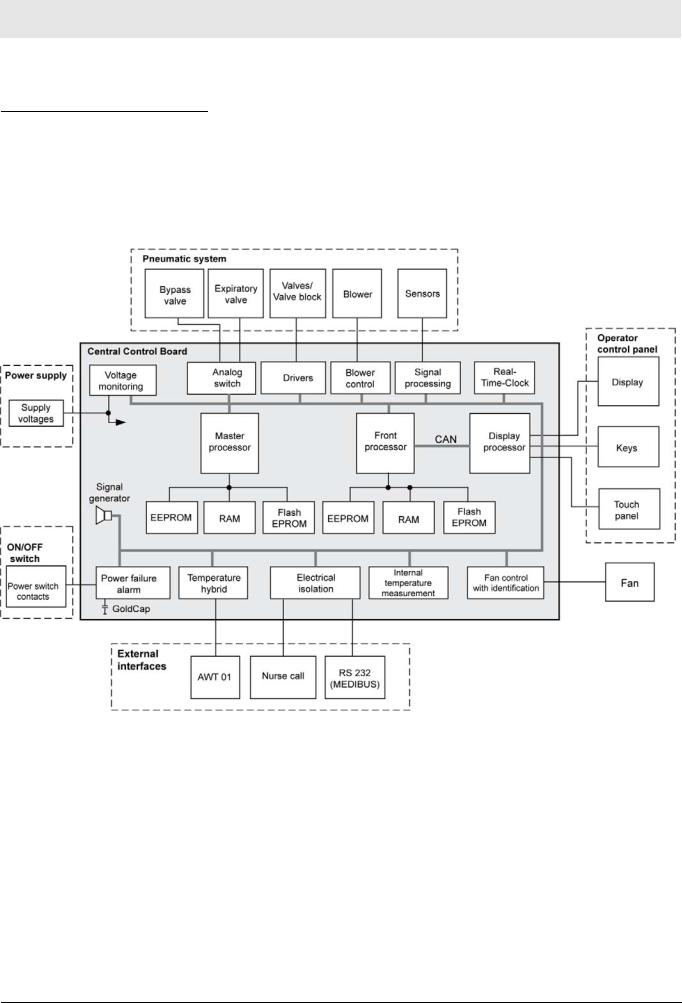
The Central Control Board is the device's central „control and monitoring unit“. It has three separate processor systems (master processor, front processor and display processor).
Three processor systems save the changeable, non-volatile data to EEPROMs.
<![endif]>No.1309_0000001227_Publication
Fig. 2 Block diagram of the Central Control Board
Master processor
The master processor has the following tasks:
–Activation of the actuators (valves, valve block, blower)
–Reading of the measured values from the sensors
–Control of the ventilation
–Monitoring of the front processor
The master processor data are cached in the RAM.
The EEPROM of the master processor system stores the calibration data of the sensors and set values such as volume.
Savina 300 |
13 |

Function descriptions
Electronic assembly
Front processor
The front processor has the following tasks:
–Interface with the display processor
–Monitoring of the master processor and display processor
–Monitoring of the input logic and the data e.g. the pixel sum
The RAM caches data from the front processor.
The EEPROM with socket of the front processor stores safety parameters, set values such as volume, software options and the operating hours.
Display processor
The display processor has the following tasks:
–Presentation of curves and parameters on the display, LEDs
–Input and operator data (keyboard, rotary encoder, touchscreen)
–Collation of data such as the pixel sum.
The EEPROM of the display processor stores user-specific display settings, such as measured value positions.
Flash EEPROMs
The device's operating system program (software) is stored in Flash
EEPROMs (rewritable memory modules).
Real-time clock
The real-time clock generates the time and date information. The real-time clock has an internal battery.
The Central Control Board incorporates the following functions:
–Processing of the signals from the sensors (O2, flow, pressure, temperature)
–Control of the blower and valves
–Monitoring of the unit functions and the supply voltages
–Actuation of the displays
–Keypad interpretation
–Provision of the internal and external interfaces
–Set values such as the volume
Mains power failure alarm
If the mains power fails, the device switches to the internal batteries which supply the device with power. If the internal batteries are discharged and the device has no external batteries, an acoustic alarm is sounded with a GoldCap and a horn.
<![endif]>No.1309_0000001227_Publication
14 |
Savina 300 |

Function descriptions
Electronic assembly
Temperature hybrid
Motor actuator
The temperature hybrid reads the data of the AWT01 sensor and converts these into digital signals. An electrical isolation occurs in this process.
Internal temperature measurement
The internal temperature measurement is a safety function. In the event of overheating (if the internal temperature of the device is too high), an alarm is sounded.
Fan actuation and fans
The fan rotates quickly after the device has been switched on to remove any residual oxygen from the device. The rotation of the fan is detected and controlled in three stages (slow, medium and fast).
Three temperature sensors control the fan.
CAN
The CAN interface is a fast, serial interface. Via the CAN interface the control unit can communicate with the electronic and pneumatic assemblies. The transmission rate is 800 kbit/s.
The motor actuator controls the blower motor. The motor actuator is located in a self-contained housing. The supply voltage for the motor actuator is +48 V and is protected by a fuse (6.3AT).
The input voltage range of the motor actuator is 12 to 52.5 V. The rotation speed is set by the Central Control Board. The control voltage for the rotation speed is 0 V to +5.00 V, corresponding to a rotation speed of 0 to 12,000 rpm. The rotation speed range is 4,000 to 12,000 rpm.
The motor actuator acquires the „actual speed signal“ and forwards it to the Central Control Board. The „actual value signal“ is 6 pulses per rotation. In the event of discrepancies in the rotation speed the Central Control Board adjusts the speed according to the deviation.
<![endif]>No.1309_0000001227_Publication
Fig. 3 Block diagram of the motor actuator
Savina 300 |
15 |
Function descriptions
Electronic assembly
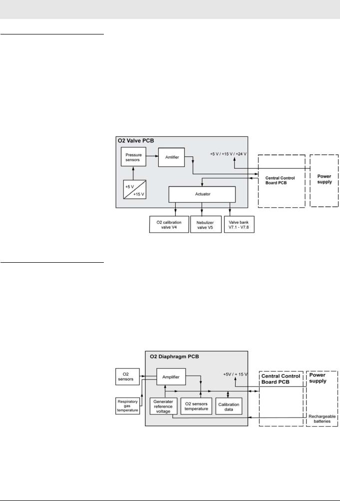
O2 Valve PCB
The O2 Valve PCB holds the pressure sensors (absolute pressure S6 and S7 and O2 supply pressure S5), the actuator for the O2 calibrating valve and the nebulizer valve and the actuator for the valve block.
The signals of the pressure sensors are amplified and routed to the Central Control Board. The supply voltage (+5 V) for the pressure sensors is generated by the O2 Valve PCB.
The valve block valves, the O2 calibrating valve and the nebulizer valve can be operated separately by an electronic switch. They are actuated by the Central Control Board.
O2 Diaphragm PCB
Fig. 4 Block diagram of the O2 Valve PCB
The O2 Diaphragm PCB amplifies the signals from the O2 sensors and measures the temperature of the O2 sensors and of the respiratory gas in the inspiration block. The temperature of the O2 sensors is required to compensate for the temperature-sensitive O2 measurements. The EEPROM on the Central Control Board stores the calibration data of the sensors. The reference voltage for the O2 sensors is generated from the voltage of the rechargeable batteries.
The supply voltages for the O2 Diaphragm PCB are +5 V and +15 V.
Fig. 5 O2 Diaphragm PCB block diagram
<![endif]>No.1309_0000001227_Publication
16 |
Savina 300 |

|
Function descriptions |
|
Electronic assembly |
|
|
Fan |
The fan takes in ambient air through the cooler and cools the blower motor. |
|
The air flow removes excess oxygen from the device. |
|
The supply voltage for the fan is +24 V. The Central Control Board regulates |
|
the speed of the fan. |
Fig. 6 |
Fan control |
|
|
|
|
|
Item |
Designation |
|
|
|
1 |
|
Supply voltage |
|
|
|
2 |
|
Target speed |
|
|
|
3 |
|
Speed signal |
|
|
|
4 |
|
Sensor supply voltage |
|
|
|
5 |
|
Ground |
|
|
|
<![endif]>No.1309_0000001227_Publication
Savina 300 |
17 |

Function descriptions
Control panel with TFT colour display
Control panel with TFT colour display
Control unit
The control panel is the interface between the unit and the user. The control panel is used to enter and display the ventilation parameters.
Membrane keypad
TFT colour display
Rotary encoder
Fig. 7 Block diagram of the control panel with TFT colour display
The keypad features the control keys and the associated LEDs.
The 12.1” TFT colour display comprises the actual display and the backlight converter. The TFT colour display has a resolution of 800 x 600 pixels.
The backlight converter generates a high voltage for the display backlighting.
The rotary knob is used to set and acknowledge the ventilation parameters. The shaft encoder transmits square signals to the processor system as it rotates, and the signals are then evaluated by the Central Control Board. The voltage supply is +5 V.
<![endif]>No.1309_0000001227_Publication
18 |
Savina 300 |

Function descriptions
Control panel with TFT colour display
Touch-panel |
Analog-resistive touch-screen |
Fig. 8 Analog-resistive touch-screen
Analog systems consist of two opposing conductive indium tin oxide (ITO) layers (x and y layer) which are actuated with a constant direct voltage. Indium tin oxide is a transparent semiconducting material.
Between the two ITO layers there are a large number of small, barely visible so-called spacer dots which ensure the two layers are kept separate.
In 8-wire systems the touch-screen has eight wires routed to the controller – four for each axis.
When the touch-screen is touched at a certain point where the two ITO layers are located an electrical contact is produced. The resistance of this contact results in a different voltage at each point. The change in voltage is then used to define the x and y coordinates.
The Central Control Board controls the communication between the processor system and the touch-screen. The correct position is determined with the aid of the relevant software drivers. The analog touch-screen works very precisely, and provides a high resolution.
<![if ! IE]><![endif]>No.1309_0000001227_Publication
Savina 300 |
19 |

Function descriptions
Pneumatic assembly
Pneumatic assembly
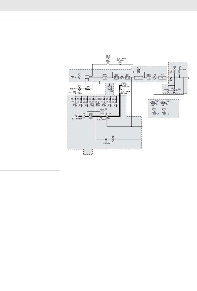
Functional diagram
Fig. 9 |
Functional diagram |
|
|
|
|
|
|
|
|
Item |
Designation |
|
|
|
|
|
|
F1 |
Micro-filter (AIR) |
|
|
|
|
|
|
F2 |
Filter (O2) |
|
|
|
|
|
|
F4 |
Filter (inspiratory flow sensor) |
|
|
|
|
|
|
F5 |
Filter (Filter element) |
|
|
|
|
|
|
Volume |
Mixing chamber |
|
|
|
|
|
|
SD1 |
Suction sound insulator |
|
|
|
|
|
|
SD2 |
Sound insulator |
|
|
|
|
|
|
DR1 |
Supply pressure regulator (Oxygen) |
|
|
|
|
|
|
Gebläse |
Blower |
|
|
|
|
|
|
Kühler |
Cooler |
|
|
|
|
|
|
V1 |
Reduction valve |
|
|
|
|
|
|
V3 |
Expiratory valve |
|
|
|
|
|
|
|
|
<![endif]>No.1309_0000001227_Publication
20 |
Savina 300 |
<![endif]>No.1309_0000001227_Publication
Function descriptions
Pneumatic assembly
|
Item |
|
|
Designation |
|
|
|
|
|
|
|
|
V4 |
|
Switching valve (oxygen compensation) |
|
|
|
|
|
|
|
|
|
V5 |
|
Switching valve (nebulizer) |
|
|
|
|
|
|
|
|
|
V6.1 |
|
Calibration valve (inspiratory airway pressure sensor) |
|
|
|
|
|
|
|
|
|
V6.2 |
|
Calibration valve (expiratory airway pressure sensor) |
|
|
|
|
|
|
|
|
|
V7.1 - V7.8 |
|
Oxygen metering valves |
|
|
|
|
|
|
|
|
|
V8 |
|
Pilot valve for emergency vent valve |
|
|
|
|
|
|
|
|
|
V9 |
|
Emergency vent valve |
|
|
|
|
|
|
|
|
|
S1 |
|
Inspiratory flow sensor |
|
|
|
|
|
|
|
|
|
S2 |
|
Expiratory flow sensor |
|
|
|
|
|
|
|
|
|
S3.1 |
|
O2 sensor 1 (measurement and control) |
|
|
|
|
|
|
|
|
|
S3.2 |
|
O2 sensor 2 (Monitoring) |
|
|
|
|
|
|
|
|
|
S4.1 |
|
Inspiratory airway pressure sensor (located in inspiratory branch) |
|
|
|
|
|
|
|
|
|
S4.2 |
|
Expiratory airway pressure sensor (located in expiratory branch) |
|
|
|
|
|
|
|
|
|
S5 |
|
Supply pressure sensor (oxygen) |
|
|
|
|
|
|
|
|
|
S6 |
|
Pressure sensor 1 (absolute pressure) |
|
|
|
|
|
|
|
|
|
S7 |
|
Pressure sensor 2 (absolute pressure) |
|
|
|
|
|
|
|
|
|
D1 |
|
Safety pressure-limitting valve (passive, approx. 120 mbar) |
|
|
|
|
|
|
|
|
|
D2 |
|
Emergency air valve (-3 mbar to -6 mbar) |
|
|
|
|
|
|
|
|
|
D3 |
|
Expiratory non-return valve |
|
|
|
|
|
|
|
|
|
D4 |
|
Inspiratory non-return valve |
|
|
|
|
|
|
|
|
|
D5 |
|
Flush flow non-return valve |
|
|
|
|
|
|
|
|
|
D6 |
|
Non-return valve (LPO) |
|
|
|
|
|
|
|
|
|
R1 |
|
Flush flow metering unit (0,1 L/min at 30 mbar) |
|
|
|
|
|
|
|
|
|
R2 |
|
O2 calibration metering unit for (0,1 L/min, integrated in valve block) |
|
|
|
|
|
|
|
|
|
R3 |
|
Metering unit for O2 measurement (0,2 L/min at 30 mbar, Sensor 3.1) |
|
|
|
|
|
|
|
|
|
R4 |
|
Metering unit for nebulizer (10 L/min, integrated in valve block) |
|
|
|
|
|
|
|
|
|
R5.1 - R5.8 |
|
Metering units for the oxygen metering valves |
|
|
|
|
|
|
|
|
|
R6 |
|
Metering unit for O2 measurement (0,2 L/min at 30 mbar, Sensor 3.2) |
|
|
|
|
|
|
|
|
|
|
|
|
|
|
Main components |
|
The pneumatic assembly consists of the following components: |
|
||
|
|
|
– Plug-in unit |
|
|
|
|
|
– |
Valve block |
|
|
|
|
– |
Inspiratory block |
|
|
|
|
– |
Pressure measuring block |
|
|
|
|
– |
Patient system |
|
|
|
|
– |
Flow sensors |
|
|
|
|
|
|
|
|
|
|
|
Savina 300 |
21 |
Function descriptions
Pneumatic assembly
Device functions
Ventilation function |
When the device is switched on the power supply unit supplies the blower |
|
motor with operating voltage. The blower motor draws in ambient air through |
|
the microfilter F1, the volume and the sound insulators SD1 and SD3. The |
|
blower motor compresses the gas intake to an overpressure up to max. 140 |
|
mbar at a delivery rate of up to 180 L/min. The air compressed by the blower |
|
motor passes through the sound insulator SD4, the cooler, the sound insula- |
|
tor SD2, the filter F4 and the inspiratory flow sensor S1 to the inspiratory non- |
|
return valve D4. The controller operates the blower motor during a breath at a |
|
constant speed. The bypass valve regulates the inspiratory pressure. The |
|
combination of the blower motor and bypass valve V1 provides a pressure |
|
source. |
Fig. 10 Detail view of functional diagram; ventilation function
The sound insulators SD1 and SD2 on the inlet and outlet sides of the blower motor reduce the sound level.
The bypass valve V1 is operated such that the desired respiratory pressure is applied to the blower outlet, and thus to the patient. If the patient needs a high flow during the inspiratory phase, the gas flows in part or in its entirety from the blower motor outlet to the patient and the gas flow through the bypass valve V1 is reduced. During the expiratory phase all the blower gas flows through the bypass valve V1.
The cooler reduces the respiratory gas temperature down to a permissible range.
<![if ! IE]><![endif]>No.1309_0000001227_Publication
22 |
Savina 300 |
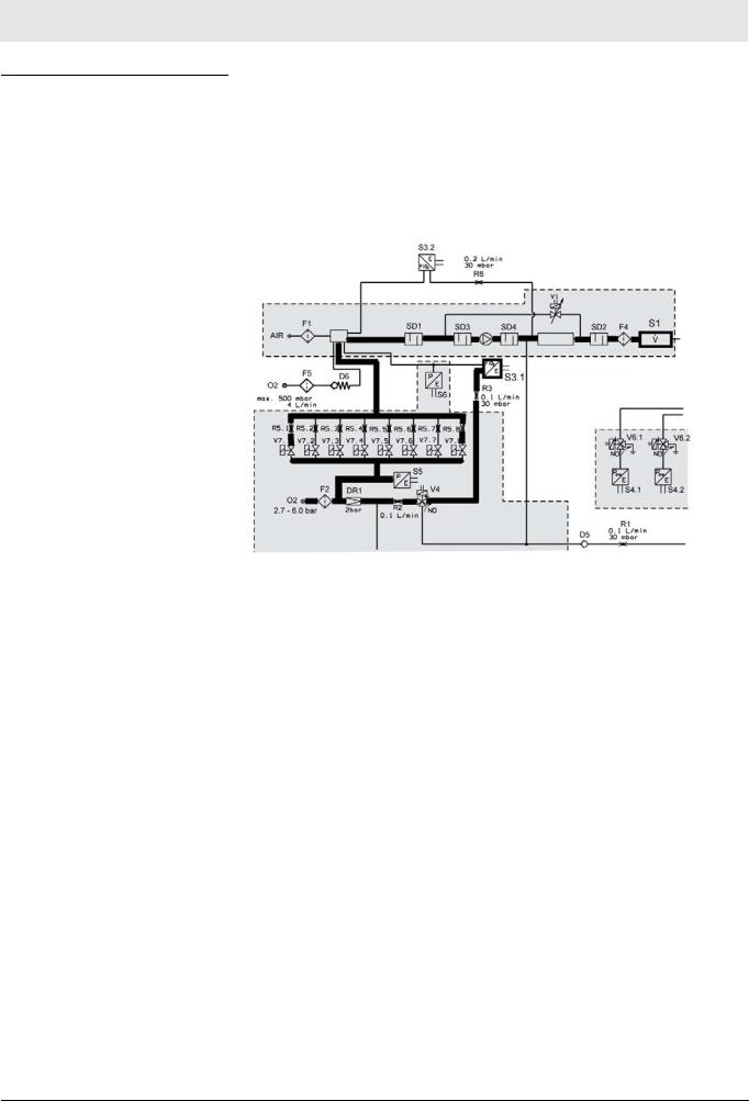
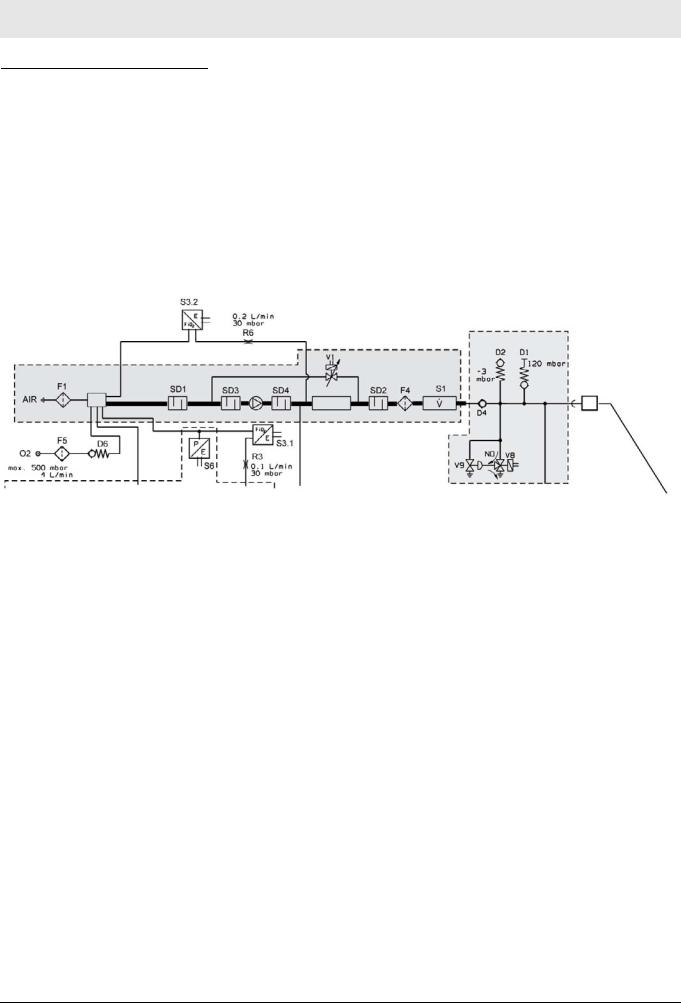
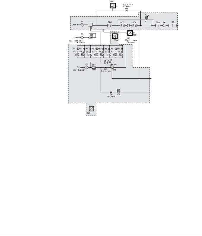
O2 mixture with O2 high pressure
Function descriptions
Pneumatic assembly
In order to be able to ventilate with an increased O2 concentration, the unit must be supplied with 2.7 to 6.0 bar O2. The oxygen is filtered by the filter F2. With the aid of the digital valve block consisting of 8 digital solenoid valves, oxygen is metered into the volume (mixing chamber). The amount of metered oxygen depends on the pre-set O2 concentration and on the inspiratory flow rate measured by the flow sensor S1. The oxygen is metered in a closed control loop. In the process, the inspiratory O2 concentration is measured by the O2 sensor S 3.1.
Fig. 11 Detail view of functional diagram; O2 mixture with O2 high pressure
<![if ! IE]><![endif]>No.1309_0000001227_Publication
Savina 300 |
23 |

Function descriptions
Pneumatic assembly
O2 mixture with O2 low pressure („LPO“ option)
NOTE
Connect only O2 low pressure sources without humidifier to the device!
An O2 low pressure source without humidifier feeds the oxygen into the “LPO” connection on the back of the unit. The filter (filter element) F5 protects the non-return valve D6 from coarse particles. The oxygen flows from the non-return valve D6 into the volume (mixing chamber). In the volume (mixing chamber) it is mixed with the drawn-in and filtered fresh air.
Fig. 12 Detail view of functional diagram; O2 mixture with O2 low pressure
When no O2 low pressure source is connected to the unit, the non-return valve D6 prevents gas from escaping during normal operation.
NOTE
In „LPO“ mode, the valve block in the O2 supply is not actuated.
<![if ! IE]><![endif]>No.1309_0000001227_Publication
24 |
Savina 300 |
Function descriptions
Pneumatic assembly
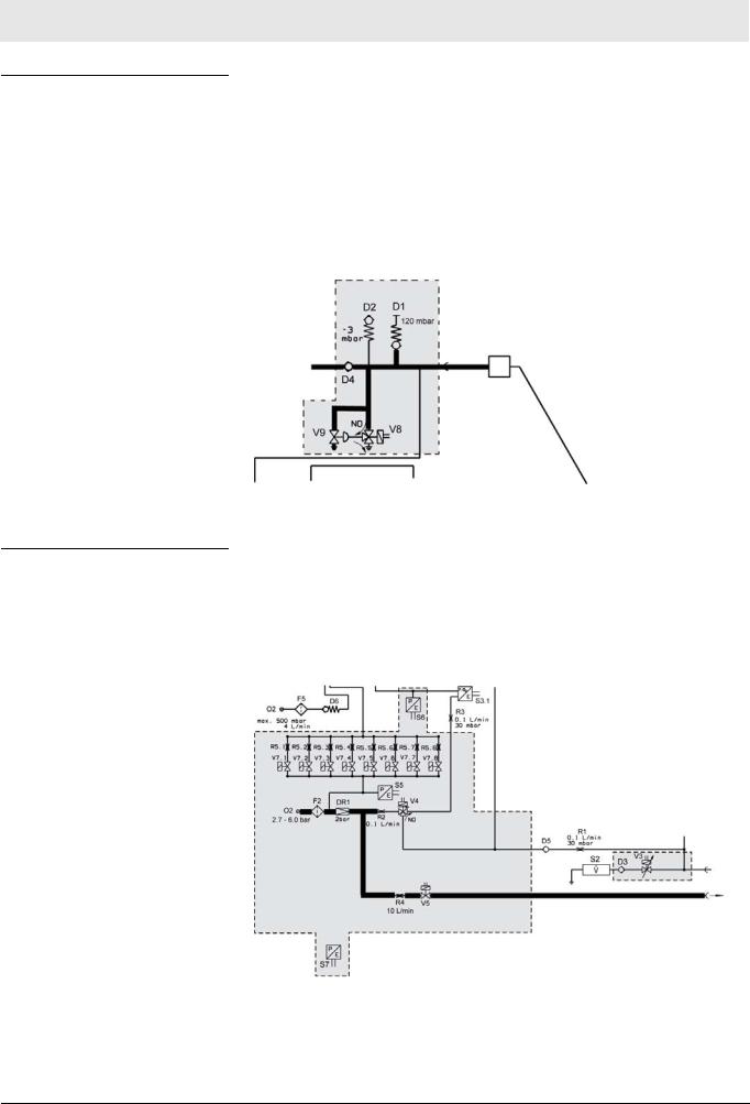
Pneumatic safety devices
The pneumatic safety valve D1 ensures that the ventilation pressure cannot rise above 120 mbar. In the event of inspiratory stenosis the pressure is limited by opening the expiratory valve. The mechanical vacuum valve D2 ensures (except in the case of inspiratory stenosis) that the patient can breathe ambient air in case of a fault.
The pneumatic emergency vent valve V9 relieves the pressure in the breathing system in a case of expiratory stenosis if the pressure cannot be relieved through the expiratory valve. To do so, the electric emergency vent valve (pilot valve) V8 actuates the emergency vent valve V9 accordingly.
Drug nebulizer
Fig. 13 Detail view of functional diagram; pneumatic safety devices
The drug nebulizer is operated with 100% oxygen. The pressure regulator DR1 ensures in the case of widely varying supply pressure (2.7 to 6.0 bar) that the pneumatic drug nebulizer receives a constant supply pressure of
2 bar.During the nebulizing phase the solenoid valve V5 operates in an “inspiration” (open position) and “expiration” (closed position) cycle. When the nebulizer function is inactive the nebulizer switching valve V5 is closed.
<![endif]>No.1309_0000001227_Publication
Fig. 14 Detail view of functional diagram; drug nebulier
Savina 300 |
25 |
Function descriptions
Pneumatic assembly
O2 calibration function
During operation, the switching valve (oxygen compensation) V4 is set to “measurement” – that is, the connection between the inspiratory side and the oxygen sensor is open. During oxygen sensor calibration oxygen passes to the oxygen sensor. This layout permits “online” calibration of the oxygen sensor S3.1 during ventilation. The oxygen sensor S3.2 must be calibrated manually (patient disconnected).
O2 sensor detection
Fig. 15 Detail view of functional diagram; O2 calibration function
The device has an oxygen sensor detector which is necessary for the „LPO“ option.
<![endif]>No.1309_0000001227_Publication
26 |
Savina 300 |
|
Function descriptions |
|
Pneumatic assembly |
|
|
Sensors |
The pressure sensor (absolute pressure) S6 measures the atmospheric pres- |
|
sure necessary for oxygen measurement and for volume application. The |
|
pressure sensor (absolute pressure) S7 monitors the pressure sensor (abso- |
|
lute pressure) S6.The oxygen sensor S3.1 generates the signal for the dis- |
|
played „FiO2“ measured value and the signal to control the inspiratory |
|
oxygen concentration. The oxygen sensor S3.2 monitors the oxygen sensor |
|
S3.1 |
Fig. 16 Detail view of functional diagram; pressure sensors and oxygen sensor
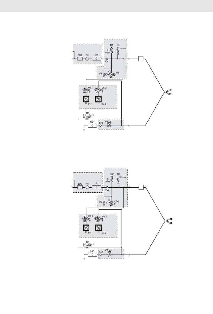
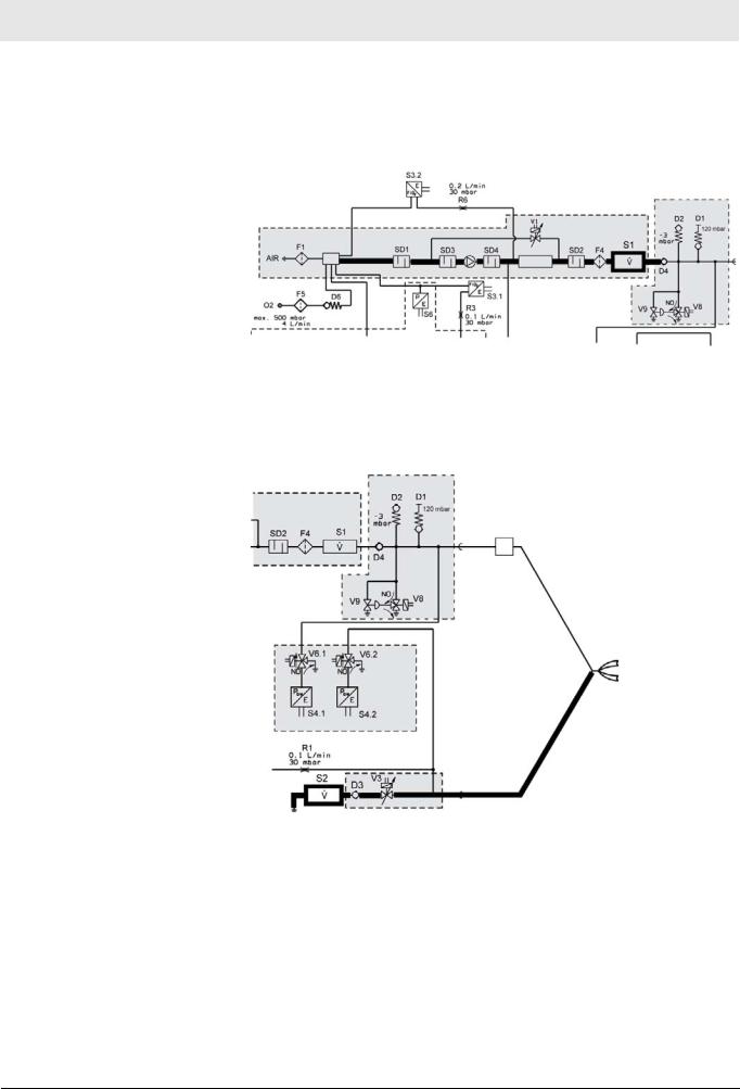
The airway pressure sensor S4.1 measures the pressure in the inspiratory branch. The airway pressure sensor S4.2 measures the pressure in the expiratory branch. The output signals of the airway pressure sensors are needed
<![if ! IE]><![endif]>No.1309_0000001227_Publication
Savina 300 |
27 |
Function descriptions
Pneumatic assembly
to determine the airway pressure and for control and monitoring purposes. The airway pressure is measured on the basis of the measured value from the airway pressure sensor in the respective no-flow branch.
Fig. 17 Detail view of functional diagram; airway pressure sensors
The calibration valves V6.1 and V6.2 enable calibration of the inspiratory and expiratory airway pressure sensors. During calibration, the corresponding calibration valve interrupts the connection to the ventilation circuit and switches the airway pressure sensor to ambient pressure.
Fig. 18 Detail view of functional diagram; calibration valves
<![if ! IE]><![endif]>No.1309_0000001227_Publication
28 |
Savina 300 |
<![endif]>No.1309_0000001227_Publication
Function descriptions
Pneumatic assembly
Flow sensor S1 measures the inspiratory gas flow. The measurement variable is used to calculate the necessary oxygen flow and to actuate the oxygen metering valves V7.1 to V7.8 in order to control the breaths and monitor the device functions. The flow sensor includes a temperature measurement function to measure the inspiratory gas temperature.
Fig. 19 Detail view of functional diagram; flow sensor
The flow sensor S2 measures the gas flow through the expiratory valve. The flow sensor is a temperature-compensated hot-wire anemometer with no flow direction detector. With this signal the patient is monitored (e.g. the minute volume).
Fig. 20 Detail view of functional diagram; flow sensor
Expiration is executed with the directly actuated expiratory valve V3.
The expiratory valve has the following functions:
–PEEP control during the expiratory phase
–Close the breathing system during the inspiratory phase.
Savina 300 |
29 |

– This page has been intentionally left blank –
<![if ! IE]><![endif]>No.1309-0000001227_Publication
30 |
Savina 300 |
 Loading...