

Page 1
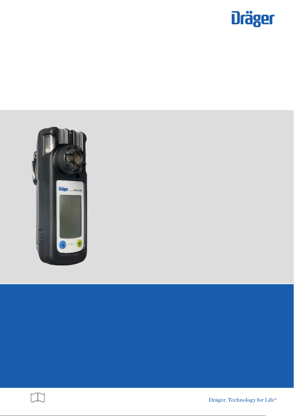
Dräger X-am® 5100
Visit: www.thesafetyequipmentstore.com or besafe@thesafetyequipmentstore.com for sales and service.
(MQG 0020)
Technical Manual
Page 2

Page 3

Contents
1 For Your Safety . . . . . . . . . . . . . . . . . . . . . . . . . . . 4
1.1 Follow the Instructions for Use . . . . . . . . . . . . . . . . 4
1.2 Maintenance . . . . . . . . . . . . . . . . . . . . . . . . . . . . . . 4
1.3 Accessories . . . . . . . . . . . . . . . . . . . . . . . . . . . . . . . 4
1.4 Safe coupling with electrical devices . . . . . . . . . . . . 4
1.5 Use in areas subject to explosion hazards . . . . . . . 4
1.6 Safety symbols used in this Technical Manual . . . . 4
2 Description . . . . . . . . . . . . . . . . . . . . . . . . . . . . . . 5
2.1 Product overview . . . . . . . . . . . . . . . . . . . . . . . . . . . 5
2.2 Intended Use . . . . . . . . . . . . . . . . . . . . . . . . . . . . . . 5
2.3 Intended operating area and operating conditions . 5
2.4 Tests and Approvals . . . . . . . . . . . . . . . . . . . . . . . . 6
3 Use . . . . . . . . . . . . . . . . . . . . . . . . . . . . . . . . . . . . . 7
3.1 Preparations for use . . . . . . . . . . . . . . . . . . . . . . . . 7
3.2 Configuration . . . . . . . . . . . . . . . . . . . . . . . . . . . . . 10
3.3 Performing the bump test . . . . . . . . . . . . . . . . . . . 11
3.4 During use . . . . . . . . . . . . . . . . . . . . . . . . . . . . . . . 12
3.5 Identifying Alarms . . . . . . . . . . . . . . . . . . . . . . . . . 12
4 Menu functions . . . . . . . . . . . . . . . . . . . . . . . . . . 13
4.1 Calling the Info Mode . . . . . . . . . . . . . . . . . . . . . . 13
4.2 Calling the Info-Off Mode . . . . . . . . . . . . . . . . . . . 13
4.3 Quick Menu . . . . . . . . . . . . . . . . . . . . . . . . . . . . . . 13
4.4 Adjustment menu . . . . . . . . . . . . . . . . . . . . . . . . . 14
5 Calibrating the instrument . . . . . . . . . . . . . . . . . 15
5.1 Adjustment interval: . . . . . . . . . . . . . . . . . . . . . . . . 15
5.2 Performing a fresh air adjustment . . . . . . . . . . . . . 15
5.3 Performing a sensitivity adjustment . . . . . . . . . . . 16
6 Replacing the Sensors . . . . . . . . . . . . . . . . . . . . 18
7 Troubleshooting . . . . . . . . . . . . . . . . . . . . . . . . . 19
7.1 Warning messages . . . . . . . . . . . . . . . . . . . . . . . . 19
7.2 Fault messages . . . . . . . . . . . . . . . . . . . . . . . . . . . 20
8 Maintenance . . . . . . . . . . . . . . . . . . . . . . . . . . . . 21
8.1 Maintenance intervals . . . . . . . . . . . . . . . . . . . . . . 21
8.2 Cleaning . . . . . . . . . . . . . . . . . . . . . . . . . . . . . . . . 21
9 Disposal . . . . . . . . . . . . . . . . . . . . . . . . . . . . . . . . 22
9.1 Disposal of electrical and electronic appliances . . 22
9.2 Electrochemical sensors . . . . . . . . . . . . . . . . . . . . 22
10 Technical Data . . . . . . . . . . . . . . . . . . . . . . . . . . . 23
11 Ordering list . . . . . . . . . . . . . . . . . . . . . . . . . . . . . 24
12 Declaration of Conformity . . . . . . . . . . . . . . . . . 25
Contents
Dräger X-am 5100 3
Page 4
For Your Safety
1 For Your Safety
1.1 Follow the Instructions for Use
Any use of the instrument requires full understanding and strict
observation of the Instructions for Use supplied with the
instrument. The instrument is only to be used for the purposes
specified here.
1.2 Maintenance
The maintenance intervals and measures specified in this
Technical Manual as well as the specifications in the
Instructions for Use/data sheets
sensors used must be carefully observed. Repairs to the
instrument may only be carried out by trained service
personnel.
1.3 Accessories
Only the accessories specified in the ordering list may be used.
1.4 Safe coupling with electrical devices
Devices which are not mentioned in the Instructions for Use or
in this Technical Manual can only be coupled electronically
after consultation with the manufacturers or an expert.
1.5 Use in areas subject to explosion hazards
Devices or components for use in explosion-hazard areas,
which have been tested and approved according to national,
European or international Explosion Protection Regulations,
may only be used under the conditions explicitly specified in
the approval and with consideration of the relevant legal
regulations. Devices and components must not be altered.
The use of faulty or incomplete parts is forbidden.
The applicable regulations must be observed at all times when
carrying out repairs on these devices or components.
1
for the DrägerSensor
® 2
1.6 Safety symbols used in this Technical Manual
This Technical Manual contains a number of warnings for risks
and hazards which might occur when using the instrument.
These warnings contain signal words to alert you to the degree
of hazard you may encounter. These signal words and
corresponding hazards are as follows:
WARNING
!
Death or serious physical injury may occur as
a result of a potential hazard situation if appropriate
precautionary measures are not taken.
CAUTION
!
Indicates a potentially hazardous situation which, if not
avoided, could result in injury or damage to property or
to the environment. Can also be used to warn against
any wanton actions.
NOTICE
i
i
Additional information on the use of the product.
1 Instructions for Use/data sheets for the utilized sensors and the PC software
CC-Vision for Dräger X-am 5100 can be downloaded on the product page
of the X-am 5100 at the following Internet address: www.draeger.com. See
also the enclosed Instructions for Use and data sheets for the sensors used.
2 DrägerSensor
4 Dräger X-am 5100
®
is a registered trademark of Dräger.
Page 5
Description
2 Description
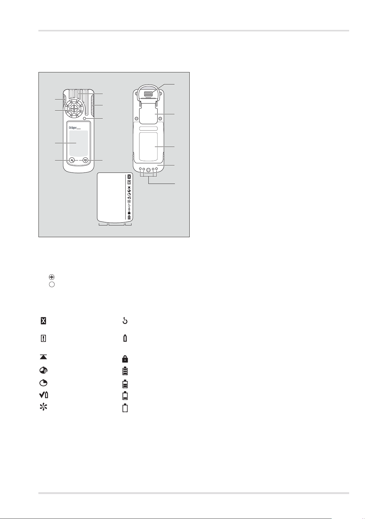
2.1 Product overview
1
2
X-am 5100
3
45
0
1
1
6
0.0
HCl ppm
7
8
9
10
11
2.2 Intended Use
Portable single gas detection instrument for the continuous
monitoring of the concentration of HCl, HF, H
in the ambient air within the working area and in explosionhazard areas.
or hydrazine
2O2
2.3 Intended operating area and operating conditions
2.3.1 Hazardous areas classified by zones
This instrument is intended for use in hazardous areas
classified as Zone 0, Zone 1 or Zone 2, or in mines in which
there is a danger of firedamp, in a temperature range of -20 °C
to +50 °C, and in areas where gases of explosion groups IIA,
IIB or IIC and temperature class T3 or T4 (depending on
batteries and rechargeable battery) may be present.
In mines, the instrument may only be used in areas with a low
risk of mechanical influence.
12 13 14
00133279.eps
1 Alarm LED 8 Fastening clip
2 Gas entry 9 Type plate
3 Display 10 Power pack
4 key 11 Charging contacts
OK
5 key 12 Measured gas display
6 Buzzer 13 Measured gas display
7 IR interface 14 Special symbols
Special symbols:
Fault message 1-button sensitivity
Warning message Standard sensitivity
Display peak value Password required
Show TWA Battery 100 % full
Show STEL Battery 2/3 full
Bump test mode Battery 1/3 full
Fresh air adjustment Battery empty
adjustment
adjustment
Dräger X-am 5100 5
Page 6
Description
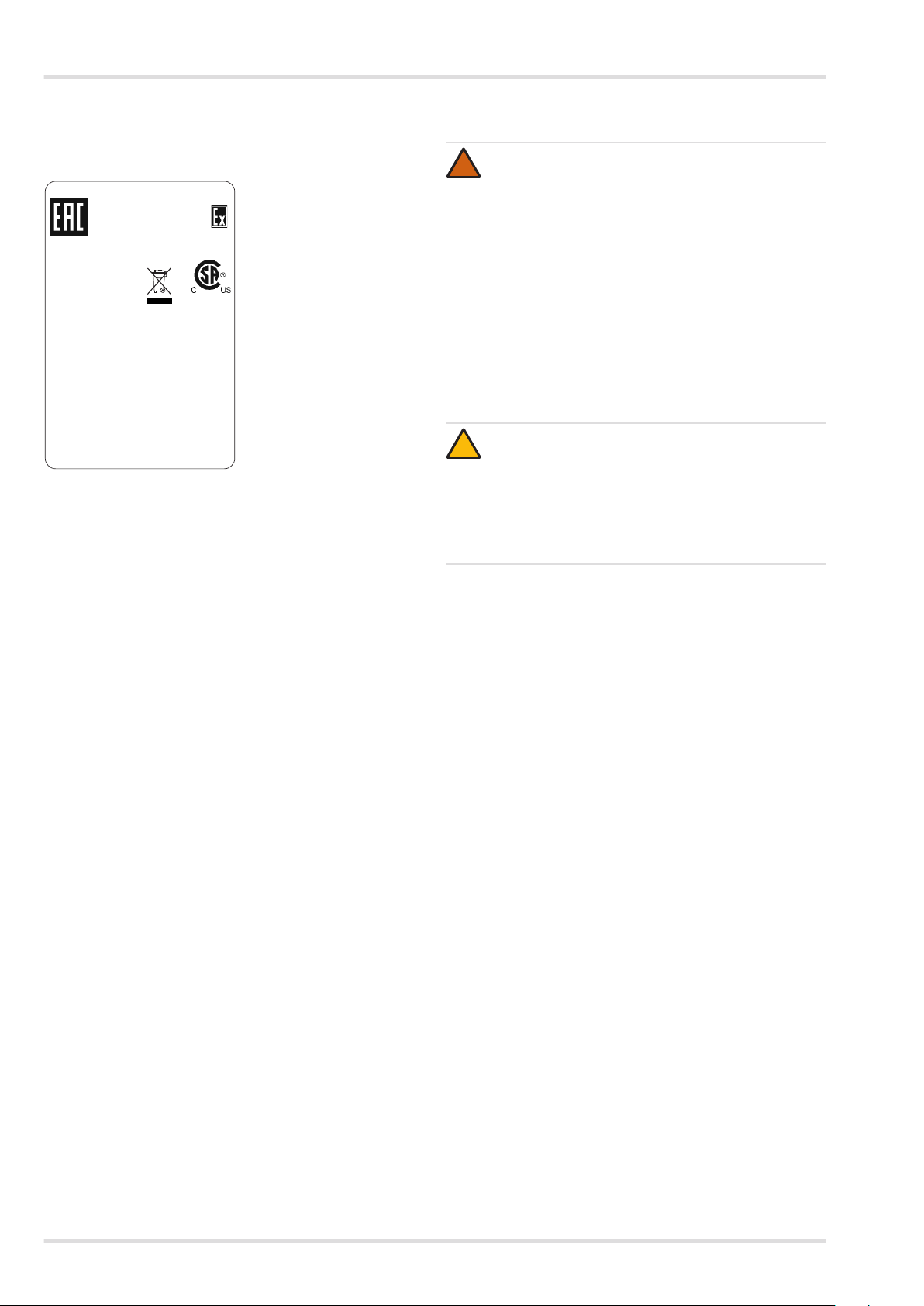
2.4 Tests and Approvals
2.4.1 Marking
TC RU C-DE.ГБ06.В.00095
PO Ex ia l X
0 Ex ia IlC T4/T3 X
Dräger Safety Type: MQG 0020
23560 Lübeck, Germany
`
C
I M1/II 1G
Ex ia I/IIC T4/T3 Ma/Ga Um=4.6V Im=1.3A
BVS 10 ATEX E 080X IECEx BVS 10.0053X
Intrinsically safe Ex ia, CSA 11 1800517
CSA: Class I, Div. 1, Groups A,B,C,D TC T4/T3
-20°C Ta +50/+40°C: see Battery Pack!
For TC T4/T3: see Battery Pack!
Warning: Read manual for safety precautions.
Do not change or charge batteries in haz loc.
Serial No.
2.4.2 Permissible power packs
Power pack 83 22 237,
approved as Type ABT 0100
Temperature class T4
-20 °C ≤ Ta ≤ +50 °C
use with alkaline batteries
Duracell Procell MN1500
0158
Class I, Zone 0, A/Ex ia IIC T4/T3 /Ga
≤ ≤
1
on a separate label
2.4.3 Safety instructions
WARNING
!
Read the safety measures in the Instructions for Use.
Do not replace or charge batteries in potentially
explosive areas. Danger of explosion!
To reduce the danger of explosion, do not mix new
batteries with old batteries and do not mix batteries
made by different manufacturers.
Always disconnect the instrument from the power pack
before carrying out any maintenance operations.
Substitution of components may impair intrinsic safety.
High off-scale readings may indicate an explosive
concentration.
CAUTION
!
Not tested in oxygen enriched atmospheres (>21 % O2).
Only use power packs ABT 0100 (Order No,
83 22 237), HBT 0000 (Order No. 83 18 704) or
HBT 0100 (Order No. 83 22 244). See marking on
power pack for approved batteries and related
temperature class.
Temperature class T3
-20 °C Ta +40 °C
use with NiMH batteries
GP 180AAHC (1800 mAh)
use with alkaline batteries
Varta Powerone 4006
Varta Powerone 4106
Panasonic Powerline LR6
Power pack 83 18 704;
approved as HBT 0000
Temperature class T4
-20 °C ≤ Ta ≤ +50 °C
Power pack 83 22 244;
approved as HBT 0100
Temperature class T4
-20 °C ≤ Ta ≤ +50 °C
1 The year of manufacture is coded by the third capital letter of the serial number:
Y = 2007, Z = 2008, A = 2009, B = 2010, C = 2011, D = 2012, E = 2013, etc.
Example: Serial No. ARCH-0054: the third letter is C, so the year of
manufacture is 2011.
6 Dräger X-am 5100
Page 7
3 Use
Use
3.1 Preparations for use
Before using the instrument for the first time, the
enclosed batteries or a charged T4 NiMH power pack
(Order No. 83 18 704 / 83 22 244) must be inserted,
see "Replacing the batteries / rechargeable batteries" on
page 8.
The X-am-5100 is ready for operation.
3.1.1 Charging the rechargeable batteries
WARNING
!
Danger of explosion!
Do not charge underground or in explosion-hazard
areas!
The chargers are not designed in accordance with the
regulations for firedamp and explosion protection.
Charge power packs type HBT 0000 or HBT 0100 with
the appropriate Dräger charger. Charge single NiMH
cells for battery holder ABT 0100 in accordance with the
manufacturer's specifications. Ambient temperature
during the charging procedure: 0 to +40 °C.
NOTICE
i
i
Even if the instrument is not in use, Dräger
recommends that you store it in the charger
(chargermodule X-am 1/2/5000, Order No. 83 18 639).
To maintain the lifetime of the batteries, charging is only
performed within a temperature range of 5 to 35 °C.
Outside this temperature range, the charging is
automatically interrupted and resumes automatically after
the temperature is within the range again.
The charging time is typically 4 hours.
A new NiMH power pack reaches its full capacity after three
complete charging/discharging cycles.
Never store the instrument for extended periods without
being connected to a power source (maximum of 2 months)
because the internal buffer battery will drain.
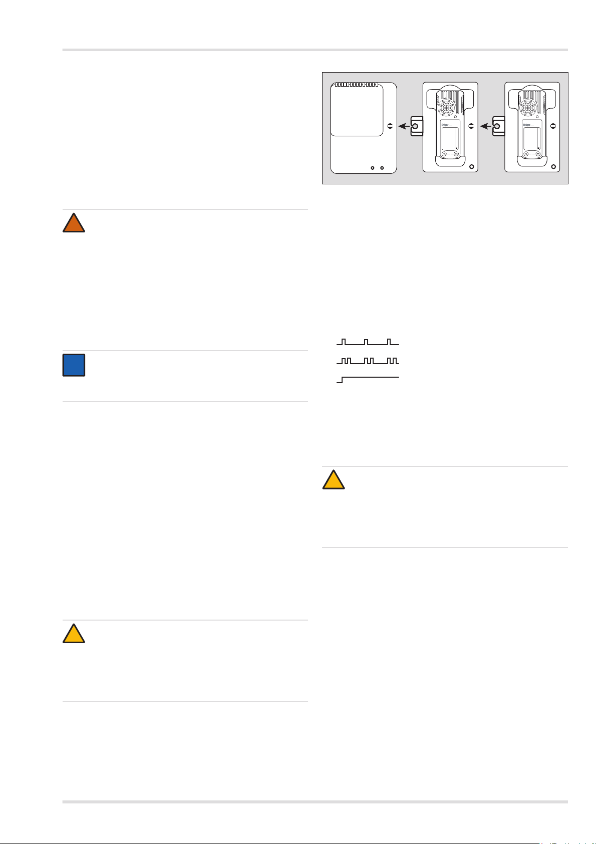
Charging with the multiple charging station
A maximum of 20 instruments can be charged at the same
time on the power pack (Order No. 83 18 805) of the
multiple charging station.
When attaching the charging modules, disconnect the
power pack from the mains supply!
CAUTION
!
Always connect or disconnect the charging modules
individually and not in groups in order to prevent the
charging station from becoming damaged. During
transportation, the power pack and the charging
modules should also always be handled individually
and without inserted instruments.
2
1
34 5 5
Position the instrument on an even and level surface.
X-am 5100
0.0 0.0
HCl ppm
0
2
1
HCl ppm
X-am 5100
0
1
00733280.eps
1. Turn the slots of the interlock into a horizontal position by
using a screwdriver or coin.
2. Insert the projecting tongue (2) of the charging module
(doubles as power feed) until it engages.
3. Close the lock (1) with a quarter turn (slot is positioned
vertically).
4. Attach additional charging modules in the same way.
5. Connect the power pack to the mains.
The green "Mains" LED (1) lights.
6. Insert the switched-off instrument into the charging module.
LED indicator (5) on the charger:
Charge
Fault
Full
If a fault occurs:
Remove the instrument from the charging module and
insert it again.
If the fault still occurs, have the charging module repaired.
It takes approx. 4 hours to fully charge an empty
rechargeable battery.
CAUTION
!
A short circuit of the charging contacts in the charging
modules, e.g., by metallic objects that have fallen in,
will not result in damage to the charging station.
It should, however, be avoided due to possible heating
hazards and incorrect displays on the charging
module.
In the event of a short circuit or if the power pack is
overloaded:
The red "Overload" LED (3) lights, and an audible alarm
sounds.
After the fault has been corrected, the alarm is switched
off automatically and the charging process is restarted.
In the event of a power failure, the instruments already
charged will be protected from discharging.
Dräger X-am 5100 7
Page 8
Use
Charging with charger module and plug-in power pack or
vehicle charging adapter
–
+
2
+
–
83 16 994 (100 ... 240 V)
83 15 635 (100 ... 240 V)
HCl ppm
X-am 5100
0.0
0
45 30 057
00933280.eps
When the power pack is used (Order No. 83 16 994) up to
5 instruments, or with power pack (Order No. 83 15 635),
up to 2 instruments can be charged at the same time.
The power pack contained in the rechargeable battery and
charging set (Order No. 83 18 785) is suitable for charging
one instrument.
When the vehicle charging adapter is used (Order
No. 45 30 057) it is recommended that each charging
module is supplied separately.
The charging process is carried out analogue to charging
with the multiple charging station.
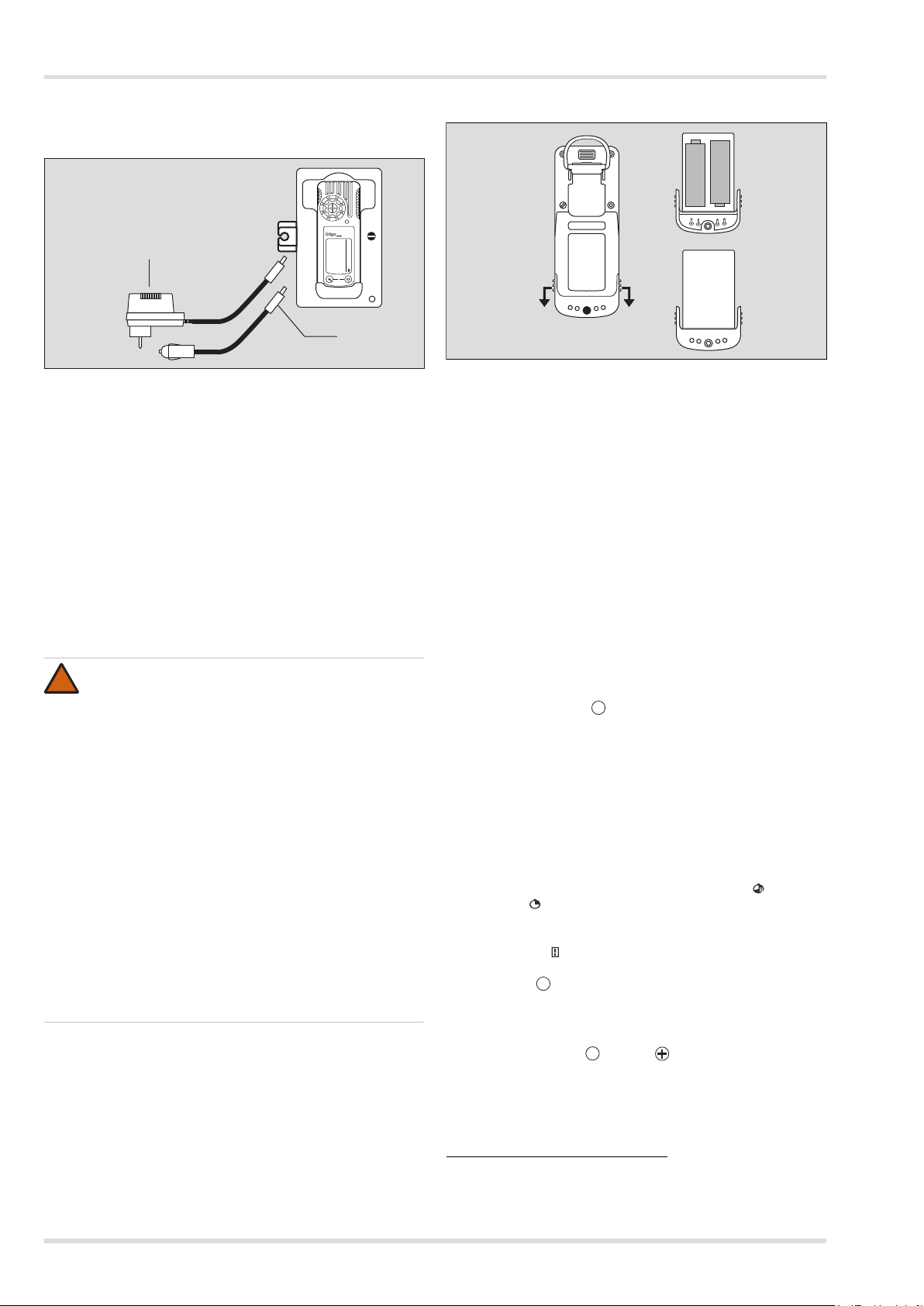
3.1.2 Replacing the batteries / rechargeable batteries
WARNING
!
Danger of explosion!
Do not replace the batteries / rechargeable batteries in
areas where there is a danger of explosion.
Do not throw used batteries into fire or try to open them
by force. Dispose of the batteries in accordance with
national regulations.
Batteries / rechargeable batteries are part of the Ex
approval.
Only the following types may be used:
Alkaline batteries – T4 – (not rechargeable)
Duracell Procell MN1500
Alkaline batteries – T3 – (not rechargeable)
Varta Powerone 4006
Varta Powerone 4106
Panasonic Powerline LR6
NiMH rechargeable batteries – T3 – (rechargeable)
GP 180AAHC (1800)
max. 40 °C ambient temperature.
3
1
00633280.eps
1. Switch off the instrument if necessary (see "Switching off
the instrument" on page 8).
2. Loosen the screw (2.0 mm hexagon socket) on the power
pack and remove the power pack.
3. Replace the alkaline batteries with new ones or the
rechargeable NiMHy batteries with charged ones – ensure
correct polarity.
4. Completely replace the T4 power pack (with sealed
rechargeable batteries, Order No. 83 18 704 / 83 22 244).
5. Insert the power pack into the instrument and tighten the
screw, the instrument switches on automatically.
After replacing the power pack T4, it is recommended that
a complete charging is carried out.
After the batteries have been replaced:
The settings and data are stored when the battery is
replaced. The sensors warm up again.
3.1.3 Switching on the instrument
1. Press and hold the key for approx. 3 seconds until the
countdown » 3 . 2 . 1 « shown in the display has elapsed.
All the display segments, including the visual, audible
and vibration alarms, are activated for a short time.
The software version is displayed.
The instrument performs a self test.
The next sensor to be calibrated is shown, together
with the days remaining until the next calibration, e.g.
» HCl ppm CAL 20 «.
The time until the bump test interval elapses is
displayed in days, e.g., » bt 123 «.
All alarm thresholds A1 and A2 as well as » « (TWA)
and » « (STEL)1, are displayed consecutively.
During the sensor warm-up period, the respective
display of the measured value flashes and the special
symbol » « (for warning) is displayed. No alarms are
issued during the sensor warm-up period.
2. Press the key to cancel the display of the activation
OK
sequence.
3.1.4 Switching off the instrument
1. Press and hold the key and key at the same time until
the countdown » 3 . 2 . 1 « shown in the display has
elapsed.
Before the instrument is switched off, the visual, audible
and vibration alarms are activated for a short time.
OK
OK
1
1 Only when activated in the instrument configuration. Delivery status: not
activated.
8 Dräger X-am 5100
Page 9

3.1.5 Before entering the workplace
WARNING
!
Before safety-related measurements, check the
calibration and recalibrate if necessary. A bump test
must be carried out in accordance with the national
regulations.
1. Switch on the instrument. The current measured values are
shown in the display.
Observe any warning » « or fault messages » «.
The instrument can be operated normally. If the warning
message does not disappear automatically during
operation, the instrument must be serviced after the end
of use.
The instrument is not ready to measure and requires
maintenance.
2. Check that the gas inlet opening on the instrument is
not covered.
Use
Dräger X-am 5100 9
Page 10

Use
3.2 Configuration
3.2.1 Standard gas configuration
Alarm A1
1
Alarm A2
1
DrägerSensor Measuring range
XS EC HF/HCI [ppm]
2
XS EC H2O2 [ppm]
XS EC N2H4 [ppm]
1 Different settings can be selected to meet customer requirements on delivery. The current setting can be checked and changed with the Dräger CC Vision
software. A version of the CC-Vision software that can be used for Dräger X-am 5100 is available for download from the product page for the X-am 5100 at the
following web address: www.draeger.com
2 Valid for HCl.
0 to 30 5 Yes No 10 No Yes
0 to 20 1 Yes No 2 No Yes
0 to 3 0.1 Yes No 0.2 No Ye s
3.2.2 Standard instrument configuration
1
threshold
1
3.2.3 Configuring the instrument
can be acknowledged
self-latching
threshold
can be acknowledged
To customise its configuration, the instrument must be
Dräger X-am 5100
Bump test mode Quick bump test
connected to a PC with the USB-DIRA adapter (Order
No. 83 17 409). Dräger CC-Vision PC software is used to
perform the configuration.
Fresh air adjustment On
Life signs (visual only) On
Disabling permitted / blocked for A2
Averaging time 15 minutes for STEL
8 hours for TWA
0
IR
X-am 5100
USB 1.1
self-latching
1 Different settings can be selected to meet customer requirements on
delivery. The current setting can be checked and changed with the
Dräger CC Vision software.
00433280.eps
Changing the standard configuration
The installed Dräger CC Vision PC software is used for
configuration.
Observe the documentation and online help of the software.
A version of the CC-Vision software that can be used for
Dräger X-am 5100 is available for download from the
product page for the X-am 5100 at the following web
address: www.draeger.com.
Reading the database and displaying it Graphically
The installed PC software Dräger GasVision is used for
reading and displaying the database.
Observe the documentation and online help of the software.
Changing the configuration: See “Troubleshooting” on
page 19.
WARNING
!
After a basic initialization has been carried out with
the Dräger CC Vision PC software, individual alarm
settings may have been changed.
10 Dräger X-am 5100
Page 11

Use
3.3 Performing the bump test
3.3.1 Manual testing without documentation of results in
1. Prepare a test gas source (e.g., cylinder, permeation oven);
2. Fit the calibration adapter
3. Connect the test gas
4. Vent the test gas into
5. Switch on the instrument.
6. Open the valve on the test gas source to let test gas flow
7. Recommendation: Wait until the instrument displays the
8. Close the valve on the test gas source.
If the concentration has now fallen under the A1 alarm
If the displays are outside of the above-mentioned ranges:
3.3.2
The "Quick bump test" or the "Extended bump test" is
Setting on delivery: Quick bump test.
the instrument memory
NOTICE
i
i
Sensor-specific features affecting the bump test are
described in the respective sensor data sheets.
the volume flow must be 0.5 L/min and the gas
concentration must be higher than the alarm threshold
concentration to be tested.
(68 06 291) to the sensor
cap.
source to the calibration
adapter.
a fume cupboard or into
0
x-am 5100
the open air (with a hose
connected to the second
connector of the calibration
adapter).
00533280.eps
WARNING
!
Never inhale the test gas. Danger to health!
Observe the hazard warnings in the relevant Safety
Data Sheets.
over the sensor.
test gas concentration with sufficient tolerance.
However, wait at least until alarm threshold A1 or A2 has
been exceeded.
If the alarm thresholds are exceeded, the instrument
displays the gas concentration in alternation with » A1 «
or » A2 « depending on the test gas concentration.
threshold:
Acknowledge the alarm.
Calibrate the instrument, see "Calibrating the instrument"
on page 15.
Bump test with documentation of results in the instrument memory.
selected using the Dräger CC Vision PC software. The
"Quick bump test" checks whether the gas concentration
has exceeded the Alarm 1 threshold (with oxygen, the
check is whether the concentration has fallen below the
Alarm 1 threshold). The "Extended bump test" checks
whether the gas concentration has exceeded the Alarm 1
threshold (with oxygen, the check is whether the
concentration has fallen below the Alarm 1 threshold) and
whether the gas concentration has reached the preset
bump test concentration.
1. Prepare a test gas source (e.g., cylinder, permeation oven);
the volume flow must be 0.5 L/min and the gas
concentration must be higher than the alarm threshold
concentration to be tested.
2. Fit the calibration adapter
(68 06 291) to the sensor
cap.
3. Connect the test gas
source to the calibration
adapter.
4. Vent the test gas into
a fume cupboard or into
0
x-am 5100
the open air (with a hose
connected to the second
connector of the calibration
adapter).
00533280.eps
WARNING
!
Never inhale the test gas. Danger to health!
Observe the hazard warnings in the relevant Safety
Data Sheets.
5. Switch on the instrument.
6. Call up the Quick Menu and select the bump test,
see "Quick Menu" on page 13.
The current gas
concentration values
and the special symbol
» « (for bump test)
flash.
7. Press the key to start
the bump test.
OK
HCl ppm
8. Open the valve on the test
gas source to let test gas
flow over the sensor.
If gas concentration
exceeds the alarm
thresholds A 1 the
10433280.eps
corresponding alarm will
occur.
If a gas alarm (Quick
bump test) is triggered or
the preset bump test
concentration (Extended
bump test) is reached
within the specified time:
The display containing the
OK
HCl ppm
current gas concentration
changes with the display
» OK «.
The bump test that was
carried out is documented
with the result and date in
10533280.eps
the instrument memory.
9. Close the valve on the test
gas source.
If the concentration has now fallen below the A1 alarm
threshold, the instrument returns to the measuring mode.
If the set bump test concentration is not reached after a
sensor-specific time interval, an instrument error is
generated.
Dräger X-am 5100 11
Page 12

Use
3.4 During use
CAUTION
!
To ensure correct measurement operation, the gas
inlet opening on the instrument must not be covered
or dirty.
The sensor cap must not be twisted.
During operation, the measured values for the measured
gas are displayed.
If a measuring range is exceeded or a negative drift occurs,
the following displays are shown instead of the measured
value display:
» «
» «
In the event of an alarm, the corresponding displays,
including the visual, audible and vibration alarms, are
activated, see "Identifying Alarms" on page 12.
i
i
(Too high concentration) or
(Negative drift).
NOTICE
Special states in which there is no measuring
operation (quick menu, calibration menu, warm-up of
sensors, password input) are indicated by a visual
signal (slow flashing of the alarm LED
).
In the case of A2, a double tone is audible and the alarm
LED flashes twice.
After leaving the area, if the concentration is less than the
alarm threshold A2:
Press the key. The alarm messages are switched off.
OK
3.5.3 STEL / TWA exposure alarm
WARNING
!
Leave the area immediately. After this alarm,
the deployment of personnel is subject to the relevant
national regulations.
The alarm is indicated by an intermittent alarm
message:
Display » A2 « and » « (STEL) or » « (TWA) and
measured value alternating:
The STEL and TWA alarm cannot be acknowledged
or cancelled.
Switch off the instrument. The values for the exposure
evaluation are deleted after the instrument is switched
on again.
3.5.4 Battery pre-alarm
The alarm is indicated by an intermittent alarm
message:
Flashing special symbol » « on the right
side of the display:
3.5 Identifying Alarms
An alarm is displayed visually, audibly and through vibration in
a specific pattern.
3.5.1 Concentration pre-alarm A1
The alarm is indicated by an intermittent alarm
message:
Display » A1 « and measured value alternating.
The pre-alarm A1 is not self-latching and stops when the
concentration has dropped below the alarm threshold A1.
In the case of A1 a single tone is audible and the alarm
LED flashes.
Acknowledging the pre-alarm:
Press the key. Only the audible alarm and the vibration
alarm are switched off.
3.5.2 Concentration main alarm A2
!
The alarm is indicated by an intermittent alarm
message:
Display » A2 and measured value alternating.
OK
WARNING
Danger to life! Leave the area immediately. A main
alarm is self-latching and cannot be acknowledged or
cancelled.
Acknowledging the pre-alarm:
Press the key. Only the audible alarm and the vibration
OK
alarm are switched off.
The battery lasts for at least another 20 minutes after the
first battery pre-alarm.
3.5.5 Battery main alarm
The alarm is indicated by an intermittent alarm
message:
Flashing special symbol » « on the right side
of the display:
The battery main alarm cannot be acknowledged or cancelled:
The instrument is automatically switched off again after
10 seconds.
Before the instrument is switched off, the visual, audible
and vibration alarms are activated for a short time.
3.5.6 Instrument alarm
The alarm is indicated by an intermittent alarm
message:
Special symbol » « displayed on the right
side of the display:
The instrument is not ready for operation.
For remedies, see "Troubleshooting" on page 19 to page 20.
Commission maintenance personnel or DrägerService to
rectify the error.
12 Dräger X-am 5100
Page 13

Menu functions
4 Menu functions
4.1 Calling the Info Mode
In measuring mode, press the key for approx. 3 seconds.
If any warning or fault messages are present, the
corresponding information or error codes are displayed
(see "Troubleshooting" on page 19 to page 20).
Press the key successively for the next display.
The peak values and the exposure values TWA
STEL
OK
1
are displayed.
Warning messages are displayed. Numerical codes
of warning messages: see "Warning messages" on
page 19.
OK
key
Fault messages are displayed. Numerical codes of
fault messages: see "Fault messages" on page 20.
OK
key
The peak values = the maximum measured values
are displayed.
OK
key
The average values of the exposures based on
a shift of, e.g., 8 hours (TWA) are displayed
OK
key
The short-term values (STEL) = average values of
the concentrations over the average value duration
are displayed
OK
key
The instrument is in measuring mode again
If no key is pressed for 10 seconds, the instrument reverts
automatically to measuring mode.
OK
1
and
4.3 Quick Menu
4.3.1 Quick menu functions
Bump test, see "Performing the bump test" on page 11.
Fresh air adjustment, see "Performing a fresh air
adjustment" on page 15.
Display and deletion of the peak values, see "Quick
menu "Displaying and deleting peak values"" on
page 13.
4.3.2 Calling the Quick Menu
The fresh air adjustment and the bump test are activated in the
quick menu on delivery. The function for displaying and
deleting peak values can additionally be activated with the
Dräger CC Vision PC software.
1. In measuring mode, press the key three times.
If functions in the quick menu have been activated using
the Dräger CC-Vision PC software, you can select these
functions using the key. If no functions have been
activated in the quick menu, the instrument remains in
measuring mode.
2. You can select the activated functions of the quick menu by
pressing the key.
Press the key to call the selected function.
Press the key to cancel the active function and to
switch to measuring mode.
If no key is pressed for 60 seconds, the instrument
reverts automatically to measuring mode.
4.3.3 Quick menu "Displaying and deleting peak values"
After the function has been
selected, the current peak
values are displayed;
the special peak values
symbol appears in the
display at the same time.
OK
12
HCl ppm
4.2 Calling the Info-Off Mode
When the instrument is in a deactivated state, press the
key.
The name of the gas, measuring unit and measuring
range limit value are displayed.
Pressing the key again exits the Info Off mode (or via
OK
timeout).
1. The peak values can be
deleted by pressing the
OK
key for 5 seconds.
The next display appears.
2. Press the key to end
OK
the function.
HCl ppm
1 Only when activated in the instrument configuration. Delivery status:
not activated.
Dräger X-am 5100 13
10133280.eps
0
10233280.eps
Page 14

Menu functions
4.4 Adjustment menu
4.4.1 Functions of the adjustment menu
Fresh air adjustment, see "Performing a fresh air
adjustment" on page 15
1-button sensitivity adjustment
Standard sensitivity adjustment
4.4.2 Calling the adjustment menu
The adjustment menu can only be accessed by entering
a password.
Password on delivery: » 001 «
The default password on delivery can be changed using
the PC software Dräger CCVision.
1. In measuring mode, press the key for at least 5 seconds.
The function for entering the password is selected.
The special symbol » « (for the "Enter password"
function) is displayed.
The display shows » 000 «, with the first digit flashing.
2. Use the key to set the
flashing digit.
3. Press the key, the
second digit starts flashing.
4. Use the key to set the
flashing digit.
5. Press the key, the third
digit starts flashing.
6. Use the key to set the
flashing digit.
7. Press the key to
confirm the password once
it has been set completely.
OK
000
OK
OK
10333280.eps
8. The adjustment menu
functions can now be selected by pressing the key.
Press the key to call the selected function.
Press the key to cancel the active function.
If no key is pressed for 10 minutes, the instrument
OK
reverts automatically to measuring mode.
14 Dräger X-am 5100
Page 15

Calibrating the instrument
5 Calibrating the instrument
WARNING
!
Always adjust the zero point first, before the sensitivity.
Otherwise the adjustment will be incorrect!
Adjustment may not be possible due to instrument and
channel errors.
Allow the sensor to warm up before the adjustment.
Warm-up time: see Instructions for Use/data sheet for the
installed DrägerSensor.
5.1 Adjustment interval:
Observe the relevant specifications in the Instructions for
Use/data sheet for the DrägerSensor installed.
For critical applications according to EN 60079-29-2
EN 45544-4
Improvement of zero point accuracy – perform a fresh air
2
and national regulations.
adjustment, see "Performing a fresh air adjustment" on
page 15.
5.2 Performing a fresh air adjustment
A fresh air adjustment can be performed to improve the zero
point accuracy.
Calibrate the instrument to fresh air, free of measured
gases or other interfering gases.
The zero point of the sensor is set to 0 during the fresh
air calibration.
Sensors that are faulty or not warmed-up will prevent the
adjustment.
In the case of sensors which are in the warm-up phase,
the message » 159 « is displayed with the special
symbol » « (for warning message).
In the case of a sensor or instrument error, the
message » 109 « is displayed with the special symbol
» « (for a fault message).
The message is cleared after 5 seconds and the
function is available again in the menu.
1. Switch on the instrument.
2. Depending on instrument configuration:
Call up the Quick Menu and select the fresh air
adjustment function » «, see "Quick Menu" on
page 13.
or
Call up the Adjustment menu and select the fresh air
adjustment function » «, see "Adjustment menu" on
page 14.
1
or
The measured values
flash.
When the measured
values have stabilized:
3. Press the key to
OK
carry out the fresh air
adjustment.
The display containing the
current gas concentration
changes with the display
» OK «.
4. Press the key to exit
OK
the calibration or wait for
approx. 5 seconds.
If a fault has occurred
during the fresh air adjustment:
The fault message » «
appears and » « is
displayed for the respective
sensor instead of the
measured value.
In this case, repeat the
fresh air adjustment.
If necessary, replace the
sensor, see "Replacing
the Sensors" on page 18.
HCl
ppm
0.0
OK
HCl ppm
HCl ppm
--
10733280.eps
10833280.eps
10933280.eps
1 EN 60079-29-2 – Guidelines for selection, installation, use and maintenance
of instruments for the detection and measurement of flammable gases and
oxygen.
2 EN 45544-4 – Electrical instruments for the direct detection and direct
concentration measurement of toxic gases and vapors – Part 4:
Guidelines for selection, installation, use and maintenance.
Dräger X-am 5100 15
Page 16

Calibrating the instrument
5.3 Performing a sensitivity adjustment
The sensitivity adjustment can optionally be performed by the
standard or by the 1-button method.
5.3.1 Standard sensitivity adjustment
CAUTION
!
Never inhale the test gas. Danger to health!
Observe the hazard warnings of the relevant Safety
Data Sheets.
NOTICE
i
i
To minimise adsorption effects, keep the length of the
hose as short as possible (maximum hose length: 1 m).
Dräger recommends using PTFE hoses.
During the sensitivity calibration, the sensitivity of the sensor is
set to the value of the test gas.
1. Fit the calibration adapter
(68 06 291) to the sensor
cap.
2. Connect the test gas
source to the calibration
adapter.
3. Vent the test gas into
a fume cupboard or into
0
the open air (with a hose
connected to the second
connector of the calibration
adapter).
4. Switch on the instrument.
5. Call up the adjustment menu, enter the password
and select the standard sensitivuty adjustment » «,
see Chapter 4.4.2 on page 14.
6. Press the key to start
the sensitivity calibration.
The name of the gas
OK
HCl
ppm
flashes.
7. Confirm with the key.
The calibration gas
OK
concentration is
displayed.
8. Press the key to
OK
confirm the calibration
gas concentration or use
the key to change
the calibration gas
concentration and
complete the process by pressing the key.
The set calibration gas concentration flashes.
9. Press the key to confirm the set value.
OK
10. Open the valve on the test gas source to let test gas flow
over the sensor.
The currently displayed measured values start to flash.
The displayed measured values change to the values
according to the gas supplied.
x-am 5100
00533280.eps
0.0
11033280.eps
OK
When the calibration is complete:
The display of the
current gas concentration
alternates with the » OK «
display.
12. Press the key or wait
for 5 seconds to quit the
calibration.
The instrument
OK
OK
HCl ppm
changes to the
measuring mode.
13. Close the valve on the test
gas source.
11133280.eps
If a fault has occurred during the sensitivity calibration:
The fault message » «
appears and » « is
displayed for the respective
sensor instead of the
measured value.
In this case, repeat the
sensitivity adjustment.
If necessary, change the
HCl ppm
--
sensor, see "Changing
sensors" on page 18.
11233280.eps
When the measured value is stabilized:
11. Press the key to carry out the calibration.
OK
16 Dräger X-am 5100
Page 17

Calibrating the instrument
5.3.2 1-button sensitivity adjustment
CAUTION
!
Never inhale the test gas. Danger to health!
Observe the hazard warnings of the relevant Safety
Data Sheets.
NOTICE
i
i
To minimise adsorption effects, keep the length of the
hose as short as possible (maximum hose length: 1 m).
Dräger recommends using PTFE hoses.
During the 1-button sensitivity adjustment, the sensitivity of the
sensor is set to the value of the test gas.
Using the Dräger CC Vision PC software, the preset
concentration values of the test gas cylinder used must be
changed in the instrument to the target values of the mixed
gas used.
1. Fit the calibration adapter
(68 06 291) to the sensor
cap.
2. Connect the test gas
source to the calibration
adapter.
3. Vent the test gas into
a fume cupboard or into
0
x-am 5100
the open air (with a hose
connected to the second
connector of the calibration
adapter).
00533280.eps
4. Switch on the instrument.
5. Call the calibration menu, enter the password and select
the 1-button sensitivity adjustment function » «,
see Chapter 4.4.2 on page 14.
6. Press the key to start
the sensitivity calibration.
7. Open the valve on the test
OK
HCl
ppm
0.0
gas source to let test gas
flow over the sensor.
The currently displayed
measured values start
to flash.
The flashing stops after
a static measured value
has been reached.
The adjustment is
now carried out
11333280.eps
automatically.
The displayed measured values change to the values
according to the gas supplied.
The automatic stability monitoring can be terminated by
pressing the key. A calibration then takes place
OK
immediately.
When the calibration is complete and the displayed
measured values have stabilized:
The display of the current
gas concentration
alternates with the » OK «
display.
8. Press the key or wait
for 5 seconds to quit the
calibration.
The instrument
OK
OK
HCl ppm
changes to the
measuring mode.
9. Close the valve on the test
gas source.
If a fault has occurred during the 1-button sensitivity
adjustment:
The fault message » «
appears and » « is
displayed for the respective
sensor instead of the
measured value.
In this case, repeat the
sensitivity adjustment.
If necessary, change the
HCl ppm
--
sensor, see "Changing
sensors" on page 18.
11433280.eps
11533280.eps
Dräger X-am 5100 17
Page 18

Replacing the Sensors
6 Replacing the Sensors
1. Connect the instrument to the PC with the USB-DIRA
adapter (Order No. 83 17 409).
0
X-am 5100
IR
USB 1.1
00433280.eps
2. Deactivate the slot using the CC-Vision PC software.
3. 4 screws on the lower shell should now be unfastened.
4. Carefully release the upper shell upwards from the
lower shell. Do not tilt the upper shell when doing this.
00133280.eps
NOTICE
i
i
When the upper shell is being released, it is possible
that the DrägerSensor will be pulled out of its mount at
the same time and remain in the upper shell.
5. Follow the remaining instructions in the CC Vision PC
software.
18 Dräger X-am 5100
Page 19

Troubleshooting
7 Troubleshooting
Fault Cause Remedy
Not possible to switch on
the instrument
Not possible to switch off
the instrument
Display » – – « Measuring range calibrated incorrectly Recalibrate the measuring range,
To display the numerical codes of the warning and fault messages in the info mode, see "Calling the Info Mode" on page 13.
7.1 Warning messages
Discharge the power pack Charge the power pack, see "Charging the
Discharge the alkaline batteries Insert new alkaline batteries, see "Replacing
The instrument is not set to measuring
mode
The instrument is configured to "Disable
prohibited"
Electronics or sensors defective Must be repaired by DrägerService.
rechargeable batteries" on page 7.
the batteries / rechargeable batteries" on
page 8.
Select measuring mode.
Configure the instrument to "Disable allowed"
with Dräger CC Vision.
see "Calibrating the instrument" on page 15.
Special symbol » « and
displayed numerical code:
152
153
154
155
159
351
352
353
354
355
356
Cause Remedy
Customer's service life counter about
to elapse
Database 90 % full Read the database soon and then clear
Database full Read the database and clear memory.
Interval for the bump test has elapsed Carry out the bump test, see "Performing the
Adjustment not possible. The menu
function cannot be carried out because
of a message which is preventing the
function (e.g., sensors in warm-up phase).
DrägerSensor XS EC1 in the warm-up
phase
DrägerSensor XS EC1 in the warm-up
phase
EC1 concentration has drifted into the
negative range
The temperature is too high Operate the instrument within the allowed
The temperature is too low Operate the instrument within the allowed
The calibration interval for DrägerSensor
XS EC1 has elapsed
Reset the service life counter using
Dräger CC Vision.
the memory.
bump test" on page 11.
Identify the message code via the info menu
and switch off, if necessary.
Wait until warm-up time is complete.
Wait until warm-up time is complete.
Perform a fresh air calibration,
see "Performing a fresh air adjustment" on
page 15.
temperature range.
temperature range.
Perform a sensitivity adjustment for
DrägerSensor XS EC1, see "Calibrating the
instrument" on page 15.
Dräger X-am 5100 19
Page 20

Troubleshooting
7.2 Fault messages
Special symbol » « and
displayed numerical code:
102 The customer's service life counter
103 The instrument is defective The instrument must be repaired by
104 Check sum error program code The instrument must be repaired by
105 The bump test interval has elapsed Carry out the bump test, see "Calibrating the
106 The calibration interval has elapsed
107 Bump test error Perform bump test, see "Performing the
108 The instrument is defective The instrument must be repaired by
109 The menu function cannot be carried out
301 No valid zero point adjustment of the
302 No valid sensitivity adjustment of the
303 The measured value of DrägerSensor XS
304 Dräger Sensor XS EC1 not inserted or
305 Error during bump test of Dräger Sensor
326 Error during accelerated warm-up of
Cause Remedy
has elapsed
(at least 1 calibration interval has elapsed)
because of an error.
Dräger Sensor XS EC1
Dräger Sensor XS EC1
EC 1 is in the negative range
defective
XS EC1
Dräger Sensor XS EC1
Reset the service life counter using Dräger
CC Vision.
DrägerService.
DrägerService.
instrument" on page 15.
Perform a sensitivity adjustment,
see "Calibrating the instrument" on page 15.
bump test" on page 11, or snsitivity
adjustment, see "Calibrating the instrument"
on page 15.
DrägerService.
Identify the error code via the info menu
and switch off, if necessary.
Perform a fresh air calibration,
see "Performing a fresh air adjustment" on
page 15.
Perform sensitivity adjustment or fresh air
adjustment, see "Calibrating the instrument"
on page 15.
Perform a fresh air calibration,
see "Performing a fresh air adjustment" on
page 15.
Check DrägerSensor XS EC1,
see "Replacing the Sensors" on page 18.
Repeat bump test. If necessary, adjust or
replace the Dräger Sensor XS EC1,
see "Replacing the Sensors" on page 18.
Remove the power pack and insert it again or
replace the sensor. Sensor must not be
exposed to gas during the first 5 minutes.
20 Dräger X-am 5100
Page 21

8 Maintenance
8.1 Maintenance intervals
The instrument should be inspected and maintained by
suitably qualified persons annually (consult: EN 45544-4 –
Electrical apparatus used for the direct detection and direct
concentration measurement of toxic gases and vapours - Part
4: Guide for selection, installation, use and maintenance and
national regulations).
Calibration intervals: see Instructions for Use for the respective
DrägerSensors.
Depending on instrument configuration:
Replace the alkaline batteries, see "Replacing the
batteries / rechargeable batteries" on page 8 or charge
the battery see "Charging the rechargeable batteries"
on page 7 – after each use, at the latest after the battery
alarm has been triggered or after 2 weeks.
Calibrate the instrument – see "Calibrating the instrument"
on page 15.
In regular intervals, according to the sensors used and
the operating conditions. For sensor-specific calibration
data, refer to the Instructions for Use/data sheets for the
Dräger sensors used
Before you carry out safety-related relevant
measurements, the zero point and sensitivity of the
instruments should be tested in accordance with
national regulations.
Inspection by suitably qualified persons – every year.
The inspection intervals must be established in each
individual case and shortened if necessary, depending
on safety related considerations, engineering conditions
and the technical requirements of the equipment.
Dräger recommend that a service agreement be
concluded with Dräger Service and that repairs also be
carried out by them.
Replace the sensors, see "Replacing the Sensors" on
page 18 – if necessary, when it is no longer possible to
adjust them.
1
.
Maintenance
8.2 Cleaning
CAUTION
!
Abrasive cleaning implements (brushes etc.), cleaning
agents and cleaning solvents can destroy the dust and
water filters.
The instrument does not need any special care.
If the instrument is very dirty, clean it with a cloth.
1 Instructions for Use/data sheets for the utilized sensors and the PC software
CC-Vision for Dräger X-am 5100 can be downloaded on the product page
of the X-am 5100 at the following Internet address: www.draeger.com. See
also the enclosed Instructions for Use and data sheets for the sensors used.
Dräger X-am 5100 21
Page 22

Disposal
9 Disposal
9.1 Disposal of electrical and electronic
appliances
This product must not be disposed of as municipal waste.
This is indicated by the adjacent icon.
You can return this product to Dräger free of charge. For
information please contact the national sales organisations
and Dräger.
Batteries and rechargeable batteries must not be disposed of
as municipal waste. This is indicated by the adjacent icon.
Collect and dispose of batteries and rechargeable batteries at
battery collection centres, in accordance with applicable
regulations.
9.2 Electrochemical sensors
WARNING
!
Acid burn risk!
Do not throw them into fires or use force to open them.
As for batteries, only dispose of as special waste in
accordance with local waste disposal regulations.
Further information can be obtained from the relevant
local authority and from appropriate waste disposal
companies.
22 Dräger X-am 5100
Page 23

10 Technical Data
Ambient conditions:
During operation and storage -20 to +50 °C
Instrument data
Protection class IP 54 for instruments with sensors
Alarm volume Typically 90 dB (A) in 30 cm distance
Operation time (with 24 hours' use per day, 1 minute alarm per day)
Alkaline battery
(Order No.
83 20 240 / 83 22 239)
NiMH rechargeable battery
(Order No. 83 18 704)
NiMH HC rechargeable battery
(Order No. 83 22 244)
Dimensions approx. 130 mm x 48 mm x 61 mm (H x W x D)
Weight approx. 220 g to 250 g
CE markings Electromagnetic compatibility (Directive 2004/108/EC)
Approvals: See “Description” on page 5.
Sensor data: See data sheets for the sensors used.
(-20 to +40 °C for NiMH Type 180AAHC single cells and T3 alkaline batteries)
700 to 1300 hPa
10 to 90 % (short-term up to 95 %) relative humidity
Typically 180 hours
Typically 150 hours
Typically 180 hours
Explosion protection (Directive 94/9/EC)
Technical Data
Dräger X-am 5100 23
Page 24

Ordering list
11 Ordering list
Name and Description
Order No.
Dräger X-am 5100 83 22 750
Power supply units:
NiMH power pack T4 83 18 704
NiMH power pack HC T4 83 22 244
Alkaline power pack T3/T4
(without alkaline batteries)
Alkaline batteries T4 (2 ea.)
1
83 22 237
83 20 240
for alkaline power pack
Alkaline batteries T3 (2 ea.)
83 22 239
for alkaline power pack
Rechargeable battery and charging set
83 18 785
(includes NiMH T4 power pack,
charging module for Dräger
X-am 1/2/5000 and plug-in power pack)
Chargers:
Charging module for Dräger X-am 1/2/5000 83 18 639
Power pack with connecting cord (worldwide)
83 15 805
for a maximum of 20 Dräger
X-am 1/2/5000 charging modules)
Plug-in power pack (worldwide)
83 16 994
for a maximum of 5 Dräger
X-am 1/2/5000 charging modules)
Plug-in power pack (worldwide)
83 15 635
for a maximum of 2 Dräger
X-am 1/2/5000 charging modules)
Vehicle connecting line 12 V/24 V
45 30 057
for Dräger X-am 1/2/5000 charging module
Vehicle installation set
83 18 779
for 1 Dräger X-am 1/2/5000 charging module
Additional strap for vehicle mounting bracket 83 18 788
1 The T3/T4 alkaline power pack (Order No. 83 18 703) is not a subject of the
BVS 08 ATEX G 002 X and PFG 08 G 001 certificates.
Name and Description
Order No.
Accessories for measured value
acquisition and configuration:
Dräger GasVision 83 14 034
Dräger CC Vision 64 08 515
PC communications set for 1 Dräger
83 18 761
X-am 1/2/5000 with USB port and
Dräger CC Vision
PC communications set for 2 Dräger
83 18 762
X-am 1/2/5000 with USB port,
Dräger CC Vision and bar code reader
USB DIRA with USB cable (USB infrared
83 17 409
adaptor for communication Dräger X-am
1/2/5000 – PC)
Calibration/adjustment accessories:
Test gas cylinder 10 ppm HCl 68 12 107
Test gas cylinder 10 ppm SO
2
68 10 645
On demand controller 83 16 556
Standard controller 68 10 397
Calibration adapter 68 06 291
Sensors:
DrägerSensor XS EC HF/HCl 68 09 140
DrägerSensor XS EC H2O
DrägerSensor XS EC N2H
2
4
68 09 170
68 09 190
24 Dräger X-am 5100
Page 25

12 Declaration of Conformity
Declaration of Conformity
Dräger X-am 5100 25
Page 26

Page 27

Page 28

Dräger Safety AG & Co. KGaA
Visit: www.thesafetyequipmentstore.com or besafe@thesafetyequipmentstore.com for sales and service.
Revalstraße 1
23560 Lübeck, Germany
Tel +49 451 882 0
Fax +49 451 882 20 80
www.draeger.com
90 33 280 - TH 4638.230
© Dräger Safety AG & Co. KGaA
Edition 04 - April 2014 (Edition 01 - July 2011)
Subject to alteration
 Loading...