

Page 1
Instructions for Use
Air-Shields Resuscitaire
WARNING
To properly use this medical device, the user must
obtain a full understanding of the performance
characteristics of this medical device prior to use
by carefully reading these Instructions for Use.
Radiant Warmer Products
Models WBR82, RW82, and WMRW82
International Version
Page 2

This page intentionally left blank.
Page 3

Trademarks
AutoBreath™ is a trademark of Draeger Medical Systems, Inc.
Care-For-Me™ is a trademark of Draeger Medical Systems, Inc.
Critter Covers® is a registered trademark of Draeger Medical Systems, Inc.
Nylok® is a registered trademark of Nylok Fastener Corporation.
Resuscitaire® is a registered trademark of Draeger Medical Systems, Inc.
VentStar™ is a trademark of Draeger Medical Systems, Inc.
Page 4

This page intentionally left blank.
Page 5

PROPRIETARY AND CONFIDENTIAL DRAFT 5 Feb 04
Table of Contents
Section 1: Symbol Definition and Intended Use
Symbol Definition. . . . . . . . . . . . . . . . . . . . . . . . . . . . . . . . . . . . . . . . . . . . . . . . . . . . . . . . . . . . . . . 1-1
Dictionary of Common Terms . . . . . . . . . . . . . . . . . . . . . . . . . . . . . . . . . . . . . . . . . . . . . . . . . . . . . 1-4
Intended Use . . . . . . . . . . . . . . . . . . . . . . . . . . . . . . . . . . . . . . . . . . . . . . . . . . . . . . . . . . . . . . . . . . . 1-6
Section 2: Introduction, Features, and Specifications
Introduction. . . . . . . . . . . . . . . . . . . . . . . . . . . . . . . . . . . . . . . . . . . . . . . . . . . . . . . . . . . . . . . . . . . . 2-1
Warmer Module . . . . . . . . . . . . . . . . . . . . . . . . . . . . . . . . . . . . . . . . . . . . . . . . . . . . . . . . . . . . . 2-1
Cart/Bassinet (Resuscitaire Birthing Room Warmer (WBR82) and Cart only). . . . . . . . . . . . . 2-1
Bassinet (Resuscitaire Radiant Warmer (RW82) only) . . . . . . . . . . . . . . . . . . . . . . . . . . . . . . . 2-1
Controller . . . . . . . . . . . . . . . . . . . . . . . . . . . . . . . . . . . . . . . . . . . . . . . . . . . . . . . . . . . . . . . . . . 2-1
Blender Module (Optional). . . . . . . . . . . . . . . . . . . . . . . . . . . . . . . . . . . . . . . . . . . . . . . . . . . . . 2-2
Resuscitation Module (Optional) . . . . . . . . . . . . . . . . . . . . . . . . . . . . . . . . . . . . . . . . . . . . . . . . 2-2
Resuscitation Module without Autobreath™ Infant Resuscitator . . . . . . . . . . . . . . . . . . . . 2-3
Resuscitation Module with AutoBreath™ Infant Resuscitator . . . . . . . . . . . . . . . . . . . . . . 2-5
Suction . . . . . . . . . . . . . . . . . . . . . . . . . . . . . . . . . . . . . . . . . . . . . . . . . . . . . . . . . . . . . . . . . 2-7
Suction Line Filter . . . . . . . . . . . . . . . . . . . . . . . . . . . . . . . . . . . . . . . . . . . . . . . . . . . . . . . . 2-8
Gas Supply Module (Optional). . . . . . . . . . . . . . . . . . . . . . . . . . . . . . . . . . . . . . . . . . . . . . . . . . 2-8
Apgar Timer . . . . . . . . . . . . . . . . . . . . . . . . . . . . . . . . . . . . . . . . . . . . . . . . . . . . . . . . . . . . . . . . 2-8
Weigh Scale . . . . . . . . . . . . . . . . . . . . . . . . . . . . . . . . . . . . . . . . . . . . . . . . . . . . . . . . . . . . . . . . 2-8
Alarms. . . . . . . . . . . . . . . . . . . . . . . . . . . . . . . . . . . . . . . . . . . . . . . . . . . . . . . . . . . . . . . . . . . . . 2-9
High Temperature . . . . . . . . . . . . . . . . . . . . . . . . . . . . . . . . . . . . . . . . . . . . . . . . . . . . . . . . . 2-9
Check Patient . . . . . . . . . . . . . . . . . . . . . . . . . . . . . . . . . . . . . . . . . . . . . . . . . . . . . . . . . . . . 2-9
Probe . . . . . . . . . . . . . . . . . . . . . . . . . . . . . . . . . . . . . . . . . . . . . . . . . . . . . . . . . . . . . . . . . . . 2-9
Baby Temperature. . . . . . . . . . . . . . . . . . . . . . . . . . . . . . . . . . . . . . . . . . . . . . . . . . . . . . . . . 2-9
Power Failure . . . . . . . . . . . . . . . . . . . . . . . . . . . . . . . . . . . . . . . . . . . . . . . . . . . . . . . . . . . . 2-9
System Failure . . . . . . . . . . . . . . . . . . . . . . . . . . . . . . . . . . . . . . . . . . . . . . . . . . . . . . . . . . . 2-9
Blender Differential Bypass (Optional) . . . . . . . . . . . . . . . . . . . . . . . . . . . . . . . . . . . . . . . 2-10
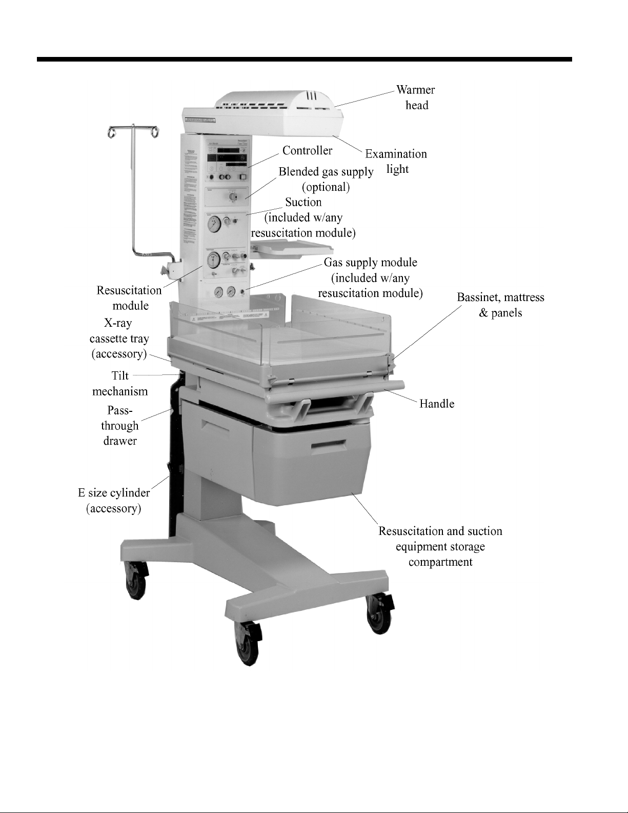
Features of the Resuscitaire Birthing Room Warmer (WBR82) . . . . . . . . . . . . . . . . . . . . . . . . . . 2-11
Features of the Resuscitaire Radiant Warmer (RW82). . . . . . . . . . . . . . . . . . . . . . . . . . . . . . . . . . 2-12
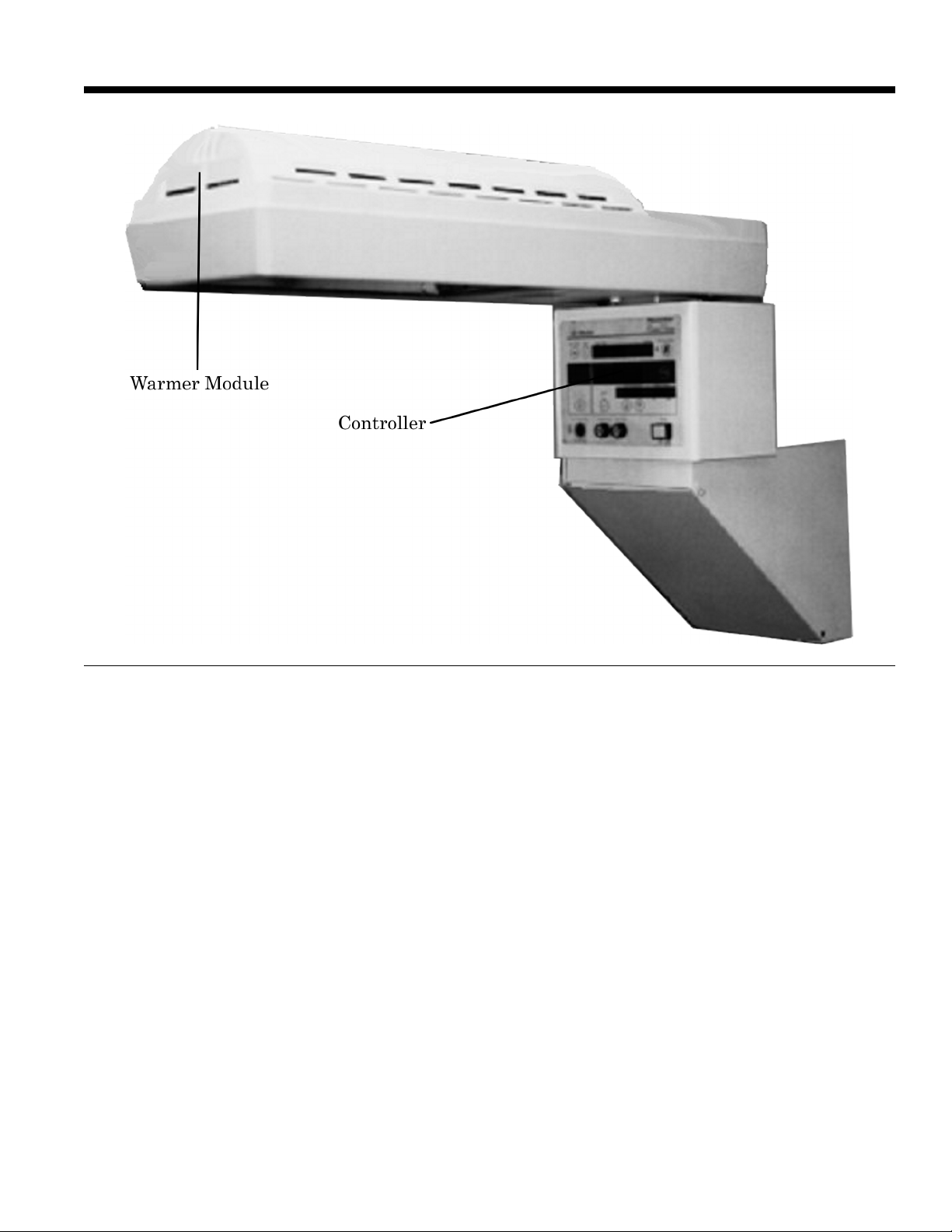
Features of the Resuscitaire Wall Mounted Radiant Warmer (WMRW82). . . . . . . . . . . . . . . . . . 2-13
Standard Features . . . . . . . . . . . . . . . . . . . . . . . . . . . . . . . . . . . . . . . . . . . . . . . . . . . . . . . . . . . 2-13
Bassinet (Resuscitaire Birthing Room Warmer (WBR82) and Resuscitaire Radiant
Warmer (RW82) only) . . . . . . . . . . . . . . . . . . . . . . . . . . . . . . . . . . . . . . . . . . . . . . . . . . . . 2-13
Warmer Module . . . . . . . . . . . . . . . . . . . . . . . . . . . . . . . . . . . . . . . . . . . . . . . . . . . . . . . . . 2-13
Controller . . . . . . . . . . . . . . . . . . . . . . . . . . . . . . . . . . . . . . . . . . . . . . . . . . . . . . . . . . . . . . 2-13
Optional Features (Resuscitaire Birthing Room Warmer (WBR82) and Resuscitaire
Radiant Warmer (RW82) only) . . . . . . . . . . . . . . . . . . . . . . . . . . . . . . . . . . . . . . . . . . . . . . . . 2-14
i
Page 6

PROPRIETARY AND CONFIDENTIAL DRAFT 5 Feb 04
Accessories . . . . . . . . . . . . . . . . . . . . . . . . . . . . . . . . . . . . . . . . . . . . . . . . . . . . . . . . . . . . . . . . 2-14
Specifications . . . . . . . . . . . . . . . . . . . . . . . . . . . . . . . . . . . . . . . . . . . . . . . . . . . . . . . . . . . . . . . . . 2-16
Standard Features . . . . . . . . . . . . . . . . . . . . . . . . . . . . . . . . . . . . . . . . . . . . . . . . . . . . . . . . . . . 2-16
Optional Features (Resuscitaire Birthing Room Warmer (WBR82) and Resuscitaire
Radiant Warmer (RW82) only) . . . . . . . . . . . . . . . . . . . . . . . . . . . . . . . . . . . . . . . . . . . . . . . . 2-18
Accessories (WBR82 and RW82 only) . . . . . . . . . . . . . . . . . . . . . . . . . . . . . . . . . . . . . . . . . . 2-20
Alarms. . . . . . . . . . . . . . . . . . . . . . . . . . . . . . . . . . . . . . . . . . . . . . . . . . . . . . . . . . . . . . . . . . . . 2-20
Regulations, Standards, and Codes. . . . . . . . . . . . . . . . . . . . . . . . . . . . . . . . . . . . . . . . . . . . . . 2-21
Device Classification (EN60601 Medical Electrical Equipment Part I: General
Requirements for Safety) . . . . . . . . . . . . . . . . . . . . . . . . . . . . . . . . . . . . . . . . . . . . . . . . . . 2-21
Electromagnetic Compatibility (EMC) Guidance and Manufacturer’s Declarations. . . . . 2-22
Section 3: Precautions and Safety Tips
Precautions . . . . . . . . . . . . . . . . . . . . . . . . . . . . . . . . . . . . . . . . . . . . . . . . . . . . . . . . . . . . . . . . . . . . 3-1
Electrical Precautions . . . . . . . . . . . . . . . . . . . . . . . . . . . . . . . . . . . . . . . . . . . . . . . . . . . . . . . . . 3-4
Explosion Precautions. . . . . . . . . . . . . . . . . . . . . . . . . . . . . . . . . . . . . . . . . . . . . . . . . . . . . . . . . 3-4
Oxygen Precautions . . . . . . . . . . . . . . . . . . . . . . . . . . . . . . . . . . . . . . . . . . . . . . . . . . . . . . . . . . 3-4
Low-Flow Microblender Precautions . . . . . . . . . . . . . . . . . . . . . . . . . . . . . . . . . . . . . . . . . . . . . 3-6
Resuscitation Precautions . . . . . . . . . . . . . . . . . . . . . . . . . . . . . . . . . . . . . . . . . . . . . . . . . . . . . . 3-7
AutoBreath™ Infant Resuscitator Precautions. . . . . . . . . . . . . . . . . . . . . . . . . . . . . . . . . . . . . . 3-9
Suction Precautions. . . . . . . . . . . . . . . . . . . . . . . . . . . . . . . . . . . . . . . . . . . . . . . . . . . . . . . . . . 3-11
System Precautions . . . . . . . . . . . . . . . . . . . . . . . . . . . . . . . . . . . . . . . . . . . . . . . . . . . . . . . . . . 3-11
Electromagnetic Compatibility Precautions . . . . . . . . . . . . . . . . . . . . . . . . . . . . . . . . . . . . . . . 3-12
Safety Tips . . . . . . . . . . . . . . . . . . . . . . . . . . . . . . . . . . . . . . . . . . . . . . . . . . . . . . . . . . . . . . . . . . . 3-13
Warning Labels. . . . . . . . . . . . . . . . . . . . . . . . . . . . . . . . . . . . . . . . . . . . . . . . . . . . . . . . . . . . . 3-16
Section 4: Installation and Assembly
Installation . . . . . . . . . . . . . . . . . . . . . . . . . . . . . . . . . . . . . . . . . . . . . . . . . . . . . . . . . . . . . . . . . . . . 4-1
Assembly of the Resuscitaire Birthing Room Warmer (WBR82) . . . . . . . . . . . . . . . . . . . . . . . . . . 4-2
Warmer . . . . . . . . . . . . . . . . . . . . . . . . . . . . . . . . . . . . . . . . . . . . . . . . . . . . . . . . . . . . . . . . . . . . 4-2
Cart and Bassinet . . . . . . . . . . . . . . . . . . . . . . . . . . . . . . . . . . . . . . . . . . . . . . . . . . . . . . . . . . . . 4-5
Assembly of the Resuscitaire Radiant Warmer (RW82) . . . . . . . . . . . . . . . . . . . . . . . . . . . . . . . . . 4-6
Warmer . . . . . . . . . . . . . . . . . . . . . . . . . . . . . . . . . . . . . . . . . . . . . . . . . . . . . . . . . . . . . . . . . . . . 4-6
Assembly of the Resuscitaire Wall Mounted Radiant Warmer (WMRW82). . . . . . . . . . . . . . . . . 4-10
Mounting of the Resuscitaire Wall Mounted Radiant Warmer (WMRW82). . . . . . . . . . . . . . 4-12
Operational Checkout Procedure . . . . . . . . . . . . . . . . . . . . . . . . . . . . . . . . . . . . . . . . . . . . . . . 4-14
Controller . . . . . . . . . . . . . . . . . . . . . . . . . . . . . . . . . . . . . . . . . . . . . . . . . . . . . . . . . . . . . . 4-14
Mechanical Operation. . . . . . . . . . . . . . . . . . . . . . . . . . . . . . . . . . . . . . . . . . . . . . . . . . . . . 4-16
Resuscitation Equipment (Optional). . . . . . . . . . . . . . . . . . . . . . . . . . . . . . . . . . . . . . . . . . 4-19
Resuscitation Module (Optional) . . . . . . . . . . . . . . . . . . . . . . . . . . . . . . . . . . . . . . . . . . . . 4-22
ii
Page 7

PROPRIETARY AND CONFIDENTIAL DRAFT 5 Feb 04
Resuscitation Module with AutoBreath™ Infant Resuscitator (Optional). . . . . . . . . . . . . 4-24
Blended Gas Supply (Optional) . . . . . . . . . . . . . . . . . . . . . . . . . . . . . . . . . . . . . . . . . . . . . 4-25
Section 5: Instructions for Use
Instructions for Use. . . . . . . . . . . . . . . . . . . . . . . . . . . . . . . . . . . . . . . . . . . . . . . . . . . . . . . . . . . . . . 5-1
Controls, Indicators, and Connectors (Resuscitaire Birthing Room Warmer
(WBR82) shown) . . . . . . . . . . . . . . . . . . . . . . . . . . . . . . . . . . . . . . . . . . . . . . . . . . . . . . . . . . . . 5-1
Resuscitation Module . . . . . . . . . . . . . . . . . . . . . . . . . . . . . . . . . . . . . . . . . . . . . . . . . . . . . . . . 5-12
Controller . . . . . . . . . . . . . . . . . . . . . . . . . . . . . . . . . . . . . . . . . . . . . . . . . . . . . . . . . . . . . . . . . 5-13
Pre-Warm Mode . . . . . . . . . . . . . . . . . . . . . . . . . . . . . . . . . . . . . . . . . . . . . . . . . . . . . . . . . 5-13
Manual Mode . . . . . . . . . . . . . . . . . . . . . . . . . . . . . . . . . . . . . . . . . . . . . . . . . . . . . . . . . . . 5-13
Baby Mode . . . . . . . . . . . . . . . . . . . . . . . . . . . . . . . . . . . . . . . . . . . . . . . . . . . . . . . . . . . . . 5-15
Examination Light . . . . . . . . . . . . . . . . . . . . . . . . . . . . . . . . . . . . . . . . . . . . . . . . . . . . . . . . . . 5-17
Cart and Bassinet . . . . . . . . . . . . . . . . . . . . . . . . . . . . . . . . . . . . . . . . . . . . . . . . . . . . . . . . . . . 5-18
End and Side Panels . . . . . . . . . . . . . . . . . . . . . . . . . . . . . . . . . . . . . . . . . . . . . . . . . . . . . . 5-18
Bassinet Tilt Control. . . . . . . . . . . . . . . . . . . . . . . . . . . . . . . . . . . . . . . . . . . . . . . . . . . . . . 5-18
Vari-tilt Control . . . . . . . . . . . . . . . . . . . . . . . . . . . . . . . . . . . . . . . . . . . . . . . . . . . . . . . . . 5-19
Docking and Undocking (Resuscitaire Birthing Room Warmer (WBR82) only) . . . . . . . 5-19
X-Ray Cassette Tray Accessory (optional) . . . . . . . . . . . . . . . . . . . . . . . . . . . . . . . . . . . . . . . 5-20
Universal Cylinder Bracket (Optional). . . . . . . . . . . . . . . . . . . . . . . . . . . . . . . . . . . . . . . . . . . 5-20
Section 6: Cleaning, Maintenance, Replacement Parts, and Storage and Handling
Cleaning . . . . . . . . . . . . . . . . . . . . . . . . . . . . . . . . . . . . . . . . . . . . . . . . . . . . . . . . . . . . . . . . . . . . . . 6-1
General Cleaning . . . . . . . . . . . . . . . . . . . . . . . . . . . . . . . . . . . . . . . . . . . . . . . . . . . . . . . . . . . . 6-2
Cleaning Agents . . . . . . . . . . . . . . . . . . . . . . . . . . . . . . . . . . . . . . . . . . . . . . . . . . . . . . . . . . . . . 6-2
Steam Cleaning . . . . . . . . . . . . . . . . . . . . . . . . . . . . . . . . . . . . . . . . . . . . . . . . . . . . . . . . . . . . . . 6-2
Cleaning Difficult to Access Areas . . . . . . . . . . . . . . . . . . . . . . . . . . . . . . . . . . . . . . . . . . . . . . 6-2
Cleaning Painted Surfaces . . . . . . . . . . . . . . . . . . . . . . . . . . . . . . . . . . . . . . . . . . . . . . . . . . . . . 6-2
Cleaning Clear Plastic and Acrylic Surfaces . . . . . . . . . . . . . . . . . . . . . . . . . . . . . . . . . . . . . . . 6-2
Cleaning Metal Surfaces. . . . . . . . . . . . . . . . . . . . . . . . . . . . . . . . . . . . . . . . . . . . . . . . . . . . . . . 6-3
Cleaning Wood Surfaces . . . . . . . . . . . . . . . . . . . . . . . . . . . . . . . . . . . . . . . . . . . . . . . . . . . . . . 6-3
Cleaning the Reusable Skin Temperature Probe . . . . . . . . . . . . . . . . . . . . . . . . . . . . . . . . . . . . 6-3
Cleaning the Reusable Suction Bottle . . . . . . . . . . . . . . . . . . . . . . . . . . . . . . . . . . . . . . . . . . . . 6-3
Cold or Gas (Ethylene Oxide) Sterilization . . . . . . . . . . . . . . . . . . . . . . . . . . . . . . . . . . . . . . . . 6-4
Disassembly for Cleaning. . . . . . . . . . . . . . . . . . . . . . . . . . . . . . . . . . . . . . . . . . . . . . . . . . . . . . 6-4
Assembly After Cleaning . . . . . . . . . . . . . . . . . . . . . . . . . . . . . . . . . . . . . . . . . . . . . . . . . . . . . . 6-6
Maintenance . . . . . . . . . . . . . . . . . . . . . . . . . . . . . . . . . . . . . . . . . . . . . . . . . . . . . . . . . . . . . . . . . . . 6-7
Calibration . . . . . . . . . . . . . . . . . . . . . . . . . . . . . . . . . . . . . . . . . . . . . . . . . . . . . . . . . . . . . . . . . 6-7
Pneumatic System. . . . . . . . . . . . . . . . . . . . . . . . . . . . . . . . . . . . . . . . . . . . . . . . . . . . . . . . . . . . 6-7
Replacement Parts. . . . . . . . . . . . . . . . . . . . . . . . . . . . . . . . . . . . . . . . . . . . . . . . . . . . . . . . . . . . . . . 6-8
iii
Page 8

PROPRIETARY AND CONFIDENTIAL DRAFT 5 Feb 04
Storage and Handling . . . . . . . . . . . . . . . . . . . . . . . . . . . . . . . . . . . . . . . . . . . . . . . . . . . . . . . . . . . 6-10
Storage . . . . . . . . . . . . . . . . . . . . . . . . . . . . . . . . . . . . . . . . . . . . . . . . . . . . . . . . . . . . . . . . 6-10
Transport. . . . . . . . . . . . . . . . . . . . . . . . . . . . . . . . . . . . . . . . . . . . . . . . . . . . . . . . . . . . . . . 6-10
Operation . . . . . . . . . . . . . . . . . . . . . . . . . . . . . . . . . . . . . . . . . . . . . . . . . . . . . . . . . . . . . . 6-10
Disposal . . . . . . . . . . . . . . . . . . . . . . . . . . . . . . . . . . . . . . . . . . . . . . . . . . . . . . . . . . . . . . . . . . . . . 6-10
Section 7: Troubleshooting
Troubleshooting . . . . . . . . . . . . . . . . . . . . . . . . . . . . . . . . . . . . . . . . . . . . . . . . . . . . . . . . . . . . . . . . 7-1
System Fail Error Codes . . . . . . . . . . . . . . . . . . . . . . . . . . . . . . . . . . . . . . . . . . . . . . . . . . . . . . . . . . 7-3
iv
Page 9
PROPRIETARY AND CONFIDENTIAL DRAFT 5 Feb 04
Section 1
Symbol Definition
and Intended Use
Symbol Definition
This manual contains different typefaces and icons designed to improve readability and increase
understanding of its content. Note the following examples:
• Standard text—used for regular information.
• Boldface text—emphasizes a word or phrase.
• NOTE:—sets apart special information or important instruction clarification.
• The symbol below highlights a WARNING or CAUTION:
Warning and Caution
– A WARNING identifies situations or actions that may affect patient or user safety. Disregarding a
warning could result in patient or user injury.
– A CAUTION points out special procedures or precautions that personnel must follow to avoid
equipment damage.
• The symbol below highlights an ELECTRICAL SHOCK HAZARD WARNING:
Electrical Shock Hazard Warning
• The symbol below indicates Attention: Consult accompanying documents:
Attention: Consult Accompanying Documents
This product contains different icons designed to increase understanding. Note the following examples:
• The symbol below indicates Type B equipment with an F-type isolated (floating) applied part:
Type B Equipment with an F-Type Isolated (Floating) Applied Part
1 - 1
Page 10

PROPRIETARY AND CONFIDENTIAL DRAFT 5 Feb 04
• The symbol below indicates a disposable suction bottle:
Disposable Suction Bottle
• The symbol below indicates a reusable suction bottle with suction line filter:
Reusable Suction Bottle
• The symbol below indicates a patient:
Patient
• The symbol below indicates the Suction Line Filter:
Suction Line Filter
• The symbol below indicates the Power On/Off key:
Power On/Off Key
• The symbol below indicates the Celsius/Fahrenheit Selection key:
Celsius/Fahrenheit Selection Key
• The symbol below indicates the Temperature Override Mode (>37°C) key:
Temperature Override Mode (>37°C) Key
• The symbols below indicates the Set Temperature keys:
1 - 2
Set Temperature Keys
Page 11

PROPRIETARY AND CONFIDENTIAL DRAFT 5 Feb 04
• The symbol below indicates the Apgar Timer keys:
Apgar Timer Keys
• The symbol below indicates the Procedural Silence indicator:
Procedural Silence Indicator
• The symbol below indicates the Silence/Reset key:
Silence/Reset Key
• The symbol below indicates the Mode Select key:
Mode Select Key
• The symbol below indicates the Keypad Lock key:
Keypad Lock Key
• The symbol below indicates the Examination Light key:
Examination Light Key
1 - 3
Page 12

PROPRIETARY AND CONFIDENTIAL DRAFT 5 Feb 04
Dictionary of Common Terms
This manual contains some terms that could be confused or can be used interchangeably. This section is
designed to increase understanding of its content. Note the following examples:
Alarm: may require user intervention, usually includes an audible beep or series of beeps
Alert: system information update, may consist of a text message on the display or an audible beep
AAP: American Academy of Pediatrics
Absolute humidity: pressure exerted by water pressure in the air, measured in mmHG (millimeters of
mercury) like blood pressure, independent of air temperature
ACOG: American College of Obstetrics and Gynecology
Apgar: named for Dr. Virginia Apgar. After birth, the infant is rated and assessed according to
Appearance, Pulse, Grimace, Airway, and Respiration
Apnea: cessation of breathing. Central apnea means the infant stops breathing. Obstructive apnea means
that something is preventing the infant from breathing
Average Db: decibel measurements smoothed to represent consistent sound measurement in the acoustic
environment (averaged over 1 minute)
Baby Mode: warmer temperature control mode whereby heater output is determined by baby
temperature via a skin temperature sensor attached to the baby's skin
NOTE:
Baby Mode, Skin Mode, and Servo Mode can be used interchangeably
Conduction: heat transfer between a surface colder or hotter than itself by direct contact
Convection: heat transfer due to warm or cold air currents
Core temperature: infant’s internal temperature
Decibel (Db): numerical expression of the relative loudness of a sound
ELBW: Extremely Low Birth Weight, micro-preemie
Evaporation: conversion of a liquid to a vapor which causes thermal dissipation when body heat is
consumed by the process
Flow Rate and Flow Rate (LPM): flow meter, LPM = liters per minute as measured by a flow meter
Foot Candle: measurement of light and the relative illumination of a surface
Hyperthermia: patient is too hot (hyper = too much; thermia = heat)
Hypothermia: patient is too cold (hypo = not enough; thermia = heat)
Hypoxia: lack of oxygen
IR: infrared, primary method of heat gain from warmer heating elements
Keratin: component of epidermal skin layer in mature skin. Premature skin has lower levels of keratin in
the epidermal (outer) skin layer, which is why premature babies have higher evaporative heat losses. This
layer normally develops about 2 weeks after birth.
LBW: Low Birth Weight (term for premature babies)
Lux: measurement of light and illumination of a surface
1 - 4
Page 13

PROPRIETARY AND CONFIDENTIAL DRAFT 5 Feb 04
Manual Mode: warmer temperature control mode where users determine the heater output to the infant
manually
Non-shivering Thermogenesis: Premature infants do not shiver. Term infants do, however, have rich
mitochondrial areas in brown adipose tissue called "brown fat" which creates heat for the infant
metabolically when required. The "brown fat" is used up in the process.
Peak Decibel: decibel measurements showing continual, meaning maximum, sound level measurement,
more reflective of subtle changes to acoustic environment
Preemie: premature infant, born <37 weeks gestation
Pre-Warm mode: Pre-Warm mode is typically associated with radiant warmers. The system will enable
the overhead heaters at 100% for 3 min, then reduces to 60% for 12 min, and then reduces again to 30%.
Thus, when the patient is admitted to the bed, it is already warm and the heating elements can respond
quickly to user or patient requirements.
Relative Humidity: amount of water vapor present in the air, expressed as a percentage and temperature
dependent
RT: Respiratory Therapist, someone who provides ventilator, resuscitation, and other pulmonary support
for patients
Radiation: heat transfer to a warm or cold surface NOT in contact
Servo Mode: closed loop systems that automatically maintain set levels based on feedback to a source.
For example, Baby mode temperature control is a servo system that controls heat processes to the patient
based on that infant's temperature.
NOTE:
Baby Mode, Skin Mode, and Servo Mode can be used interchangeably
Skin temperature: evaluation of patient temperature as measured on the skin. All of our probes are skin
measurement probes, and are attached to the skin via probe covers. Typically, there is a difference of
approximately 0.50C between skin temperature and core temperature.
Thermoneutral Zone: temperature at which an infant's temperature is regulated such that metabolic
processes are minimized, oxygen consumption is optimized, and temperature losses are minimized
Thermoregulation: ability to control and balance heat processes (convection, conduction, radiation, and
evaporation) to minimize infants’ heat losses and encourage growth
Trendelenburg: elevating one end of the mattress
UV: ultraviolet light, a component of the normal spectrum of white light
VLBW: Very Low Birth Weight baby
1 - 5
Page 14

PROPRIETARY AND CONFIDENTIAL DRAFT 5 Feb 04
Intended Use
This manual provides instructions for installation, use, operator maintenance, and troubleshooting of the
Resuscitaire® Birthing Room Warmer (WBR82), the Resuscitaire Radiant Warmer (RW82), and the
Resuscitaire Wall Mounted Radiant Warmer (WMRW82). Dräger Medical cannot be responsible for the
performance of the equipment if the user does not operate the equipment in accordance with the
instructions, fails to follow the maintenance recommendations, or makes repairs with unauthorized
components. Only qualified service personnel should calibrate or repair the unit as indicated in the
service manual. Service manuals are available from technical support.
The Resuscitaire Birthing Room Warmer (WBR82) is designed especially for labor and delivery use. It
consists of a detachable cart and bassinet and a freestanding warmer that provides heat control and
monitors skin temperature and includes an Apgar timer. The Resuscitaire Birthing Room Warmer also
includes an optional resuscitation package with suction and oxygen delivery. Other options include a
reserve gas supply and blender.
The Resuscitaire Radiant Warmer (RW82) is designed for use during labor and delivery. The Resuscitaire
Radiant Warmer consists of a bassinet, warmer, and a controller module that provides heat control,
monitoring of the skin temperature, and Apgar timing. The Variable Height (VHA) Resuscitaire Radiant
Warmer provides an adjustable mattress height. The Resuscitaire Radiant Warmer also includes the same
optional resuscitation package with suction and oxygen delivery that is available with the Resuscitaire
Birthing Room Warmer.
The Resuscitaire Wall Mounted Radiant Warmer (WMRW82) is designed specifically for labor, delivery,
and birthing room use. The Resuscitaire Wall Mounted Radiant Warmer consists of a warmer and a
controller module that provide heat control, monitoring of the skin temperature, and an Apgar timer. The
Resuscitaire Wall Mounted Radiant Warmer is installed permanently and, therefore, is not portable. There
are no resuscitation options available with this product.
All personnel who work with the equipment should read, thoroughly understand, and have ready access
to this user manual. When not in use, store the manual with the equipment. If there is anything you do not
understand, please contact your technical support representative for further information.
1 - 6
Page 15

PROPRIETARY AND CONFIDENTIAL DRAFT 5 Feb 04
Section 2
Introduction, Features,
and Specifications
Introduction
There are three versions of the Resuscitaire Radiant Warmer product: the Resuscitaire Birthing Room
Warmer (WBR82), the Resuscitaire Radiant Warmer (RW82), and the Resuscitaire Wall Mounted
Radiant Warmer (WMRW82).
Warmer Module
A controller provides Pre-Warm Mode, Manual Mode, or Baby Mode (servo skin temperature control) to
control the warmer. An examination light provides additional illumination of the mattress area. A warmer
head pivot allows the warmer to be pivoted to either side for x-ray procedures. Additionally, when the
warmer is pivoted, it continues to provide heat.
Cart/Bassinet (Resuscitaire Birthing Room Warmer (WBR82) and Cart only)
The bassinet is designed to provide maximum function and utility to aid in the care of the newborn. It is
detachable so you can transport the infant to the NICU, the general nursery, or another area of the
hospital. The side and front panels fold down to permit access to the infant. The mattress tilts at a 0°, 5°,
or 10° angle. Openings are provided on each side of the bassinet for the insertion of the accessory x-ray
cassette tray. A writing surface is available; when the writing surface is closed, it is not visible. Each cart
has a pass-through drawer and a locking front access drawer. The cart locks in place when used with a
warmer.
Bassinet (Resuscitaire Radiant Warmer (RW82) only)
The bassinet is designed to provide maximum function and utility to aid in the care of the newborn. You
may fold the side and front panels down to gain access to the infant. The mattress tilts at a 0°, 5°, or 10°
angle. Openings are provided on each side of the bassinet for the insertion of the accessory x-ray cassette
tray. A push-through drawer is supplied standard on every unit.
Controller
At power-up, the microprocessor within the controller performs a series of diagnostic tests to confirm the
proper operation of the system. During this time, all display and indicators light, except for Power Fail,
and a tone sounds.
When powered-up, the system initializes in Pre-Warm Mode, the controller starts the heater at 100%
power and maintains that setting for 3 min, reduces to 60% for 12 min, and then reduces the heater power
to 30%. During the low heat setting, the unit continues to provide heat with no low limit alarms enabled.
When operating the controller in Manual Mode, you can adjust the heater power from 0% to full power in
10% increments. After 10 min of operation in Manual Mode, the Check Patient alarm occurs. To silence
2 - 1
Page 16

PROPRIETARY AND CONFIDENTIAL DRAFT 5 Feb 04
the alarm for 10 minutes, verify the infant’s temperature, and press the Silence/Reset key. Failure to
acknowledge the Check Patient alarm by pressing the Silence/Reset key within the next 5 min causes
the heater to shut down, and an alarm occurs.
When operated in Baby Mode, the controller uses a skin temperature probe, connected between the
controller input and the infant, to automatically adjust the heater output of the warmer module to maintain
a selected set temperature.
The Apgar Timer displays the elapsed time and sounds an alert tone at 1, 5, and 10 minutes.
The Keypad Lock key, when pressed, enables or disables the Up/Down arrows, the Select Mode key,
and the >37°C key.
A procedural silence timer blocks out Low Baby Temp audible alarms for 5 minutes during routine
procedures.
Blender Module (Optional)
The blender module provides blended gas from 21% to 100% to the patient outlet on the resuscitation
module.
Resuscitation Module (Optional)
The resuscitation module contains pneumatic outlets necessary for infant resuscitation. Controls and
displays for the module are located above the bassinet on the warmer column.
Two variations of resuscitation modules exist: Resuscitation Module without Autobreath™ Infant
Resuscitator and Resuscitation Module with Autobreath™. The Resuscitation Module has an adjustable
airway pressure relief.
NOTE:
When pressure in the hose delivering gas to the patient falls below -0.4 kPa (-4 cm H2O), the one-way
valve installed at the Patient Outlet connection opens. In the unlikely failure of the gas supply, the oneway valve allows patient to inspire room air.
The resuscitation modules consist of the factory-installed components discussed on the following pages.
2 - 2
Page 17

PROPRIETARY AND CONFIDENTIAL DRAFT 5 Feb 04
Resuscitation Module without Autobreath™ Infant Resuscitator
• Patient Outlet (Resuscitation Module only)—Use the
Patient Outlet to provide continuous gas flow to the
patient. Controls are provided for Airway Pressure Relief
(maximum pressure) and Flow Rate (circuit flow
delivering 100% oxygen or blended gas). The adjustable
Airway Pressure Relief control is always operative when
used with the 15 mm tubing provided. Pressure relief is
adjustable and ranges from 0 to 4.9 kPa (0 to 50 cm
H2O/mbar). The fixed internal safety relief valve is always
operable and provides redundant maximum pressure relief
at 5.9 kPa (60 cm H2O/mbar) ± 20% and allows the patient
to inspire room air in the event of gas supply failure. The
fixed internal safety relief valve provides a maximum
pressure relief at 4.9 kPa (50 cm H2O/mbar) ± 20%.
• Airway Pressure—The airway pressure gauge monitors
the airway pressure when externally connected to patient
circuits. (UK and other local variants are connected
internally and may not have this fitting.)
• Blender—The optional blender supplies blended gas only to the Patient Outlet in the Resuscitation
Module. During operation, the resuscitation module alarms if both oxygen or air pressures are low.
• Auxiliary Outlet—The Auxiliary Outlet supplies 100% oxygen through the Auxiliary Flow control to
the auxiliary outlet connector. It is intended for oxygen enrichment of a manual bag resuscitator, for
supplemental delivery to the patient, mother, or a second neonate, such as a twin. The Auxiliary Flow
control adjusts the flow rate from 0 LPM to 15 LPM. An internal pre-set relief valve limits the
auxiliary outlet pressure to 15.7 kPa (160.1 cm H2O/mbar). For the UK only: This internal pre-set
relief valve limits the Aux Outlet pressure to 3.9 kPa (40 cm H2O/mbar).
NOTE:
The Auxiliary Outlet oxygen percentage is not adjustable. It always supplies 100% oxygen.
2 - 3
Page 18
PROPRIETARY AND CONFIDENTIAL DRAFT 5 Feb 04
WARNING:
The internal adjustable airway pressure relief is not functional with a self-inflating bag because
the patient supply is connected to the fresh gas reservoir on the self-inflating bag rather than
directly to the patient airway. When using a self-inflating bag, always use a suitable external
airway pressure relief valve connected to the patient airway. To obtain maximum flow, turn the
adjustable airway pressure relief knob to the Max. position. Failure to do so could result in infant
injury
WARNING:
Using a breathing circuit other than the one supplied may inadvertently restrict the gas flow
such that the indication of the gas flow and the adjustable airway pressure relief may be
inaccurate. Infant injury could occur.
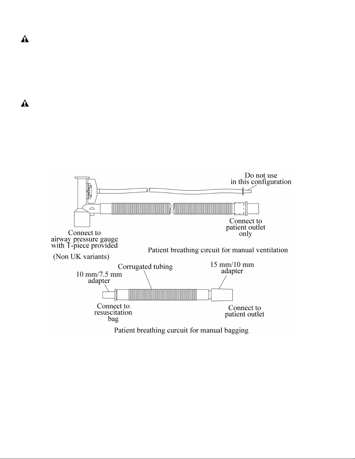
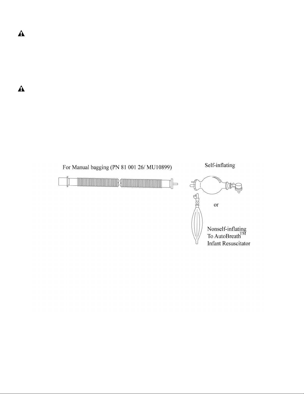
• Patient breathing and supply circuits—Use the disposable patient supply circuit (PN 81 001 27/
MU10900) for manual bagging on the Resuscitation Module.
2 - 4
Page 19
PROPRIETARY AND CONFIDENTIAL DRAFT 5 Feb 04
Resuscitation Module with AutoBreath™ Infant Resuscitator
WARNING:
Always use an airway pressure monitor if the AutoBreath™ Infant Resuscitator is to be used
unattended. Failure to do so could result in patient injury.
• AutoBreath™ Infant Resuscitator—Use the
AutoBreath™ Infant Resuscitator in conjunction with the
continuous gas flow provided by the Patient Supply submodule. The AutoBreath™ Infant Resuscitator circuit is a
gas-powered, time-cycled, continuous flow, pressurelimited resuscitator. It has a Rate (BPM) control and a fixed
I/E ratio of 1:2 nominal. An On/Off switch allows the
timing circuit to be turned on and off as needed. A PEEP
control adjusts the Positive End Expiratory Pressure in the
patient circuit.
• Patient Gas Supply—The patient gas supply circuit may be
used with the AutoBreath™ Infant Resuscitator turned on or
off to provide continuous gas flow to the patient. Controls
are provided for Airway Pressure Relief (maximum
pressure) and Flow Rate (LPM) (circuit flow delivering
100% oxygen or blended gas). The adjustable Airway
Pressure Relief control is always operative. A fixed internal
safety valve is also provided and is also always operable.
This valve provides redundant maximum pressure relief at 4.9 ± 1.0 kPa (50 cm H2O/mbar) and also
allows the patient to inspire room air in the event of gas supply failure. Negative pressure is not
available in the expiratory phase.
NOTE:
Flow Rate (LPM) is equivalent to flow meter.
• Auxiliary Outlet—The auxiliary outlet supplies 100% oxygen through the Auxiliary Flow control to
the auxiliary outlet connector. It is intended for oxygen enrichment of a manual bag resuscitator, for
supplemental delivery to the patient, mother or second neonate, such as a twin. The Auxiliary Flow
control adjusts the flow rate from 0 LPM to 15 LPM. An internal pre-set relief valve limits the
auxiliary outlet pressure to 15.7 kPa (160.1 cm H
O/mbar). This internal pre-set relief valve limits the
2
Aux Outlet pressure to 3.9 kPa (40 cm H2O/mbar).
NOTE:
Increasing back pressure may develop as the length of oxygen circuit tubing increases and tubing
diameter decreases. Install oxygen delivery tubing as intended in a clinical situation and verify through
flow measurement that approximately 15 LPM (maximum) can be achieved.
NOTE:
The Auxiliary Outlet oxygen percentage is not adjustable. It always supplies 100% oxygen.
2 - 5
Page 20
PROPRIETARY AND CONFIDENTIAL DRAFT 5 Feb 04
WARNING:
The internal adjustable airway pressure relief is not functional with a self-inflating bag because
the patient supply is connected to the fresh gas reservoir on the self-inflating bag rather than
directly to the patient airway. When using a self-inflating bag, always use a suitable external
airway pressure relief valve connected to the patient airway. To obtain maximum flow, turn the
adjustable airway pressure relief knob to the Max. position. Failure to do so could result in infant
injury.
WARNING:
Using a breathing circuit other than the AutoBreath™ Infant Resuscitator Breathing Circuit
(PN 81 000 19/ MU10850) may inadvertently restrict the gas flow such that the indication of the
gas flow and the adjustable airway pressure relief may be inaccurate. Infant injury could occur.
• Patient Breathing Circuits—Use the patient breathing circuit (PN 81 000 19/ MU10850) in
conjunction with the AutoBreath™ Infant Resuscitator. Additionally, a patient supply circuit for
manual bagging, or blow-by, (PN 81 001 26/ MU10899) may be used.
2 - 6
Page 21
PROPRIETARY AND CONFIDENTIAL DRAFT 5 Feb 04
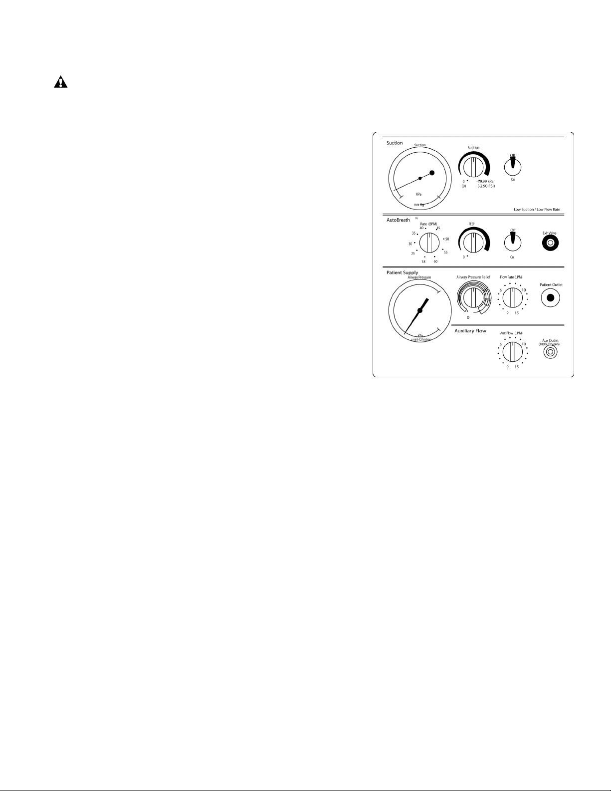
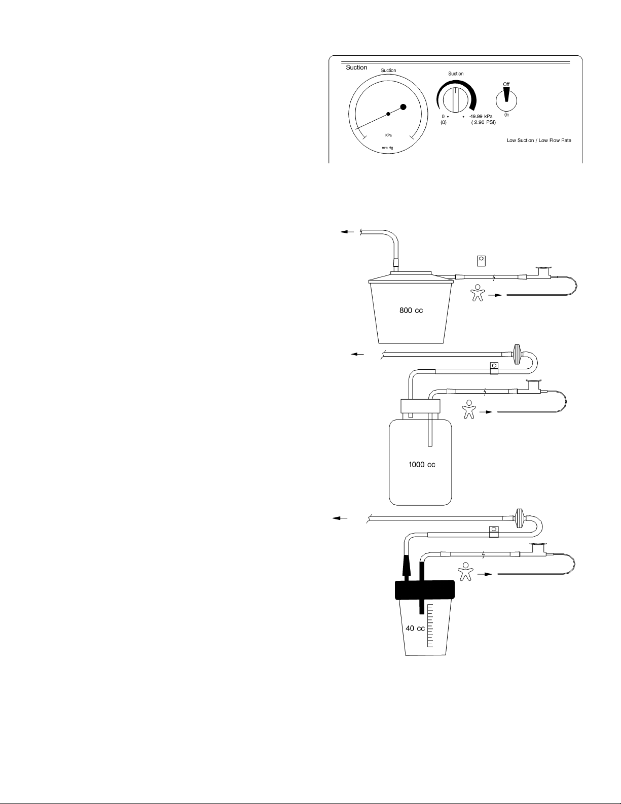
Suction
A gas-powered, venturi-generated vacuum drives
the suction circuit, which provides a negative
pressure for suctioning the patient’s airway. This
suction device is specifically intended for removal
of mucus from neonates post delivery. The suction
negative pressure is indicated on the suction gauge.
Adjust suction with the Suction control, and turn it
on or off with the On/Off switch. A fixed relief valve limits the maximum suction pressure to 150 mm
Hg (80" H2O/mbar). This suction module contains an On/Off switch and a suction control knob for
suction adjustment between 0 to 19.99 kPa (0 to 2.90 psi), minimum of 15.7 LPM at maximum.
NOTE:
The disposable suction bottle has a built-in filter.
Disposable suction bottle (PN 81 001 49/
MU10918) and the associated filter (PN 81 001 46/
MU10915)
Reusable suction bottle (PN 81 001 50/ MU10919)
and the associated filter and tubing (PN 81 001 54/
MU10923)
Reusable micro-volume suction bottle
(PN 81 001 44/ MU10913) and the associated filter
(PN 81 001 36/ MU10907), or box of 10 disposable
micro-volume suction bottles (PN 81 001 48/
MU10917), or reusable micro-volume suction kit
(PN 81 001 47/ MU10916)
2 - 7
Page 22
PROPRIETARY AND CONFIDENTIAL DRAFT 5 Feb 04
Suction Line Filter
The Suction Line Filter is a hydrophobic bacterial filter with
extension tubing. It is connected in line with the supply
connection to the suction bottle. The extension tubing connects
to the suction bottle outlet port.
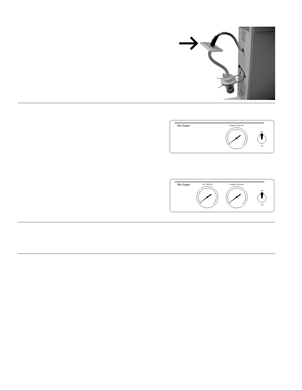
Gas Supply Module (Optional)
The gas supply module includes an On/Off switch that
controls the pipeline and cylinder gas supply to the
resuscitation module. The basic resuscitation module
includes an oxygen cylinder pressure gauge.
NOTE:
When both wall and tank gas sources are turned on, the
system may not always pull gas from the wall source. It will
pull from the source with the highest pressure. Check tank gauges to determine gas source.
On units equipped with the blender module, oxygen and air
pressure gauges are provided.
NOTE:
The Blender Module option changes the Resuscitation
Module to add the air pipeline, the tank connections, and
also adds an air gauge to the Gas Supply Module.
Apgar Timer
When the Apgar Timer is enabled, the Apgar Timer display shows elapsed minutes and seconds up to
59:59, and an alert sounds at the 1, 5, and 10 min intervals.
Weigh Scale
The scale consists of a Display Module and Weighing Platform. A microcomputer is used to determine
the weight of infants in the Resuscitaire Birthing Room Warmer and the Resuscitaire Radiant Warmer.
The infant weight remains on the digital display for several minutes. Refer to the User Manual that
accompanies the scale for additional information.
2 - 8
Page 23

PROPRIETARY AND CONFIDENTIAL DRAFT 5 Feb 04
Alarms
All alarm indicators are displayed in the upper right corner of the controller panel and illuminate when
activated.
High Temperature
When the skin temperature probe is attached to the infant and the skin temperature exceeds 39°C (102°F),
the heater automatically turns off, the High Temp indicator flashes, and the alarm sounds continuously.
To silence the alarm for 2 min, press the Silence/Reset key. After you correct the alarm condition or the
infant’s temperature falls below 38.5°C (101.3°F), the alarm automatically resets. If the skin probe
detects a temperature of 39.5°C (103.1°F), the unit shuts down, and a System Fail alarm activates.
Check Patient
After 10 min of operation in Manual Mode, the Chk Patient indicator illuminates, and the alarm sounds.
Thereafter, the Chk Patient indicator remains illuminated, and the alarm sounds every 30 s for 5 min. To
silence the alarm for 10 min, check the infant’s temperature, and press the Silence/Reset key. If the alarm
has not been acknowledged after a total of 15 additional min, the heater shuts down, and a continuous
ramping alarm sounds. To activate the heater, check the infant’s temperature, and press the Silence/Reset
key.
Probe
If the skin temperature probe fails (short- or open-circuits), or if the controller is in Baby Mode and there
is no skin temperature probe connected to the controller, the Probe indicator flashes and a ramping alarm
sounds. Additonally, the word “Lo” displays in the baby temperature display due to the baby skin
temperature probe reading <18° C ambient temperature. After correcting the alarm condition, the alarm
automatically resets.
Baby Temperature
When the temperature sensed by the skin temperature probe is 1°C above or below the Set Temperature
display setting in Baby Mode, the Baby Temp indicator flashes, and an alarm sounds, first at a low level,
then at a medium level, and then at a high level. Additionally, if the temperature is 0.2°C above the Set
Temperature display, the heater turns off automatically. To silence the alarm for 10 min, check the
infant’s temperature, and press the Silence/Reset key.
Power Failure
NOTE:
Turning off the power switch keeps the controller and heater from starting automatically when power is
returned to the unit. The settings are retained in memory.
When AC power to the unit is interrupted while the controller is on, the Power Fail indicator flashes, and
the alarm beeps. To silence the alarm, press the ON/STBY switch. When power is restored to the unit, the
alarm automatically resets, and all the settings are retained.
System Failure
If an internal malfunction is detected, the System Fail indicator flashes, and the alarm beeps. In addition,
the Baby Temperature display shows an error code, such as Er01 to Er023. A prolonged brown-out,
such as 5 min or longer, also causes this alarm. This alarm is not resettable. Refer the unit to qualified
service personnel. See “System Fail Error Codes” on page 7-3 for error codes.
2 - 9
Page 24

PROPRIETARY AND CONFIDENTIAL DRAFT 5 Feb 04
Blender Differential Bypass (Optional)
The factory-installed, optional, blender module alarms whenever the pressure differential between the
oxygen and air supplies exceed 207 kPa (30 psi) ± 14 kPa (2 psi). When this condition occurs, the blender
continues to supply whichever gas has the higher pressure: either 100% air or 100% oxygen. This is an
audible alarm only; there are no visual indicators. If a blender is present, both sources of air and oxygen
must be connected and turned on and present to prevent the Differential Bypass alarm from activating.
NOTE:
Because this alarm is pneumatically powered, either O2 or air must be present for the alarm to sound.
2 - 10
Page 25
PROPRIETARY AND CONFIDENTIAL DRAFT 5 Feb 04
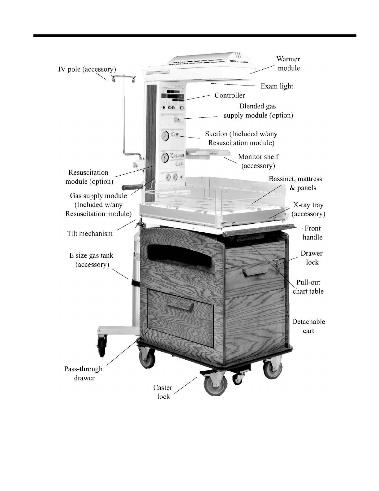
Features of the Resuscitaire Birthing Room Warmer (WBR82)
NOTE:
Suction bottle not shown. It is located on the lower right side of the warmer column.
2 - 11
Page 26
PROPRIETARY AND CONFIDENTIAL DRAFT 5 Feb 04
Features of the Resuscitaire Radiant Warmer (RW82)
2 - 12
Page 27
PROPRIETARY AND CONFIDENTIAL DRAFT 5 Feb 04
Features of the Resuscitaire Wall Mounted Radiant Warmer (WMRW82)
Standard Features
Bassinet (Resuscitaire Birthing Room Warmer (WBR82) and Resuscitaire Radiant
Warmer (RW82) only)
The bassinet provides maximum visibility and access to the infant. The bassinet tilts up in the rear to 5°
and 10°, and allows insertion of an accessory x-ray cassette tray. Vari-tilt models are continually
adjustable at ±10°.
Warmer Module
The warmer module houses a heating element and an examination light for special procedures.
Controller
The controller provides pre-warm, manual heat control, and automatic skin temperature servo-control,
and contains an Apgar Timer, skin temperature display, heater power indication, ambient temperature
sensing, diagnostic modes, alarms, keypad lock, and probe connection. All units include a reusable probe.
2 - 13
Page 28

PROPRIETARY AND CONFIDENTIAL DRAFT 5 Feb 04
Optional Features (Resuscitaire Birthing Room Warmer (WBR82) and
Resuscitaire Radiant Warmer (RW82) only)
The following factory-installed options are available:
Resuscitation module which contains connections for suction, patient or primary gas delivery (blended
air/oxygen or oxygen), auxiliary oxygen delivery, and airway pressure gauge. Two variations of
resuscitation modules exist: Resuscitation Module without Autobreath™ Infant Resuscitator and
Resuscitation Module with Autobreath™. The Resuscitation Module has an adjustable airway pressure
relief.
• Precision blender
• Oxygen pipeline and cylinder gas supply module (included on all variants)
• Oxygen/Air pipeline and cylinder gas supply module (included on blender variants only)
• Vari-tilt bassinet
• Anti-static casters
CAUTION:
Casters do not control all the Electro Static Discharge (ESD) characteristics of the device on
which they are mounted. They do, however, help prevent the build up of charge on the casters
from friction during motion.
ESD is a product of the environment and only the user/owner can control the ESD in that
environment by maintaining a conductive floor, equipping employees with ESD clothing and
control devices, etc.
Accessories
The following field-installed accessories are available (refer to Perinatal Care Accessories P/N 90 50 360
for additional parts):
Description
Organizer Tray for Air-Shields Resuscitaire slide through drawer
Optional X-Ray cassette tray below mattress, accessible from either side
Optional instrument trays available for either side of the bed
Monitor trays fit either side
IV pole fit either side
Microvolume kit (40ml)
Hydrophobic filters (package of 10)
Micro volume suction bottle (package of 10)
800 ml suction bottle (package of 20)
Reusable 750 ml (each)
Filter for reusable suction bottle (package of 25)
Reusable temperature probes (skin probe)
Disposable breathing circuit 15mm without exhalation valve for use with breathing bag (pack-
age of 25)
Disposable breathing circuit 15mm with exhalation valve (package of 25)
2 - 14
Page 29

PROPRIETARY AND CONFIDENTIAL DRAFT 5 Feb 04
Description
Optional instrument trays available for either side of the bed
Monitor shelf assembly, birthing room warmer
Insert, Drawer
Basket assembly
Rod, moounting, basket
2 - 15
Page 30

PROPRIETARY AND CONFIDENTIAL DRAFT 5 Feb 04
Specifications
Standard Features
Feature Dimension
POWER REQUIREMENTS
100V Models 100V, 50/60 Hz, 750W (non-VHA), 1300W
(VHA)
230V Models 230V, 50/60 Hz, 750W (non-VHA), 1300W
(VHA)
OVERLOAD PROTECTION
100V Models Dual Circuit Breakers 6A (non-VHA), 10A (VHA)
230V Models Dual Circuit Breakers 3A (non-VHA), 5A (VHA)
CHASSIS LEAKAGE CURRENT
100V and 120V Models 300 μA maximum
230V Models 500 μA maximum
EXAMINATION LIGHT
DISPLAYS
Skin Temperature Display Range 18 to 43°C (64.4 to 109.4°F)
Skin Temperature Display Accuracy ± 0.2°C for 31°C to 38°C (88°F to 100.4°F)
Skin Temperature Display Resolution 0.01°C (0.1°F)
Apgar Timer Display Range 0:00 to 59:59 (mins:secs)
Apgar Timer Display Accuracy 0 ± 1 s
Apgar Timer Display Resolution 1 s
MANUAL HEAT CONTROL Adjustable in 10% increments from zero to full
Heater Element Life Expectancy 1000 hours of operation
DATA PORT 2400 bits/s fixed baud rate, RS-232C compatible
MATTRESS TILT (WBR82 and RW82 only) 0, 5, and 10 degrees
BASSINET TILT- Vari-tilt (if so equipped)
(WBR82 and RW82 only)
DIMENSIONS AND WEIGHT
Mattress Height (from floor) 100 cm ± 1 cm (39.4" ± 0.4")
Mattress Height w/VHA (RW82 only) (from
floor)
Mattress Length 66.0 cm (26”)
Mattress Width 53.3 cm (21”)
Mattress Thickness 2.54 cm (1”)
Height (WBR82) 188 cm (74")
Height (RW82) 190.5 cm (75") *UK Variant add (5 cm)
Height w/VHA (RW82) 171 cm to 200.7 cm (67" to 79")
Height w/VHA and Vari-tilt option (RW82) 205.7 cm (81")
>100 Foot Candles (0.11 lumens/cm2) (50W
Quartz bulb)
power (100%).
± 10 degrees from horizontal
89.2 cm to 109.2 cm ± 1 cm (35.1" to 43" ± 0.4")
2 - 16
Page 31

PROPRIETARY AND CONFIDENTIAL DRAFT 5 Feb 04
Feature Dimension
Width (Side-to-Side) (WBR82) 71.1 cm (28")
Width (Side-to-Side) (RW82) 74.9 cm (29.5")
Depth (Front-to-Back) (WBR82) (with cart) 121.9 cm (48")
Depth (Front-to-Back) (RW82) 114.3 cm (45")
Weight w/Warmer and Cart (WBR82) 145.1 kg (320 lbs.)
Weight (RW82) 90.7 - 117.9 kg (220 - 260 lbs.)
Weight w/VHA (RW82) 100.0 - 127.3 kg (220 - 280 lbs.)
Weight w/Bracket (WMRW82) 18.1 kg (40 lbs.)
Warmer Head Rotation ±90°
ENVIRONMENTAL
Operating Temperature Range 18°C to 30°C (64.4°F to 86°F) ambient
Storage Temperature Range - 40°C to + 70°C (-40°F to + 158°F) ambient
Relative Humidity Operating Range 5% RH to 95% RH, non-condensing
2 - 17
Page 32

PROPRIETARY AND CONFIDENTIAL DRAFT 5 Feb 04
Optional Features (Resuscitaire Birthing Room Warmer (WBR82) and
Resuscitaire Radiant Warmer (RW82) only)
Feature Dimension
Wall Supply Pressure 40 psi (276 kPa) to 75 psi (517 kPa)
Cylinder Pressure 3000 psi (20684 kPa) maximum
Cylinder Length (with VHA) 70 cm (27.5")
Cylinder Length (with VHA and Spacer) ♦ 76 cm (30")
Cylinder Diameter 12 cm (4.7") maximum
Patient Gas Supply Airway Pressure Limit,
Operator Adjustable
Fixed Airway Pressure Limit, Preset (81 400
73T/ MU11369)
Primary Outlet Flow Control Range Supply
Pressure Limit
Primary Outlet Flow Control Range 0 LPM to 15 LPM
Auxiliary Supply Pressure Limit (w/o Auto-
Breath™ Infant Resuscitator feature)
Auxiliary Flow Circuit Flow Range 0 LPM to 15 LPM
Fixed Airway Pressure Limit, Preset (81 400
70/ MU11360)
Fixed Airway Pressure Limit, Preset (P/N 81
400 73T/ MU11369)
Auxiliary Supply Pressure Limit (81 400 70/
MU11360)
RESUSCITATION (w/AutoBreath™ Infant
Resuscitator feature, PN 81 400 80T/
MU11373 and 81 400 81T/ MU11375)
Wall Supply Pressure 40 psi (276 kPa) to 75 psi (517 kPa)
Cylinder Pressure 3000 psi (20684 kPa) maximum
Cylinder Length (with VHA) 70 cm (27.5")
Cylinder Length (with VHA and Spacer) 76 cm (30")
Cylinder Diameter 12 cm (5") maximum
Patient Gas Supply Airway Pressure Limit,
Operator Adjustable
Fixed Airway Pressure Limit, Preset (81 400
80T/ MU11373)
Fixed Airway Pressure Limit, Preset (81 400
81T/ MU11375)
Primary Outlet Supply Pressure Limit 160.1 cm H2O (15.7 kPa) ± 20%
0 to 50 cm H2O (0 to 4.9 kPa) ± 10%
60 cm H
O ± 10% (5.9 kPa) ± 10%
2
160.1 cm H2O (15.7 kPa) ± 20%
160.1 cm H
O (15.7 kPa) ± 10% maximum
2
50 cm H2O (4.9 kPa) ± 20%
160.1 cm H2O (15.7 kPa) ± 10%
40 cm H2O (3.9 kPa) ± 10%
0 to 50 cm H2O (0 to 4.9 kPa) ± 10%
50 cm H2O ± 20% (4.9 kPa)
60 cm H2O ± 20% (5.9 kPa)
Primary Outlet Flow Range 0 LPM to 15 LPM
Auxiliary Supply Pressure Limit (81 400 81T/
160.1 cm H2O (15.7 kPa) ± 10% maximum
MU11375)
2 - 18
Page 33

PROPRIETARY AND CONFIDENTIAL DRAFT 5 Feb 04
Feature Dimension
Auxiliary Supply Pressure Limit (81 400 80T/
40 cm H2O (3.9 kPa) ± 10% maximum
MU11373)
Auxiliary Flow Circuit Flow Range 0 LPM to 15 LPM
Auxiliary Flow Circuit Pressure 40 cm H2O (3.9 kPa) ± 10% maximum
AutoBreath™ Infant Resuscitator feature
(not available in the U.S.)
(Factory Installed Option)
I:E Ratio Fixed at 1:2 ± 20%
PEEP 0 to 18 cm H2O (0 to 1.77 kPa) ± 10%
Adjustable breath rate range 18 to 60 BPM ± 10% of setting
Adjustable Airway Pressure Relief (range of
0 to 50 ± 5 cm H2O (4.9 ± 0.5 kPa)
working pressure)
Fixed Maximum Pressure
50 cm H2O ± 10% (5.0 kPa ± 10%)
(P Lim max)
Fixed Minimum Pressure
0 kPa
(P Lim min)
Gas Supply, O2 consumption 5 LPM
System oxygen consumption 50 LPM maximum
Suction
Suction Circuit Adjustable Suction Intensity 0 kPa (0 mm Hg) to 19.99 kPa (150 mm Hg)
± 0.53 kPa (3.98 mm Hg)
Suction Circuit Maximum Vacuum -19.99 kPa (-2.90 psi) ± 0.53 kPa (0.08 psi)
Suction Circuit Maximum Flow Rate < 20 LPM (minimum of 16 LPM at maximum)
NOTE:
Suction will be driven by a 20 psi regulated
100% O2 source.
Tubing 6 mm (0.25") inner diameter by 1.8 m (6') with
sure-grip female molded connector
Total Flow Resistance (without attachments,
≤ 2 cm H
O @ 15 LPM
2
subassemblies, or components added to the
breathing system)
Total Flow Resistance (with attachments, sub-
≤ 6 cm H
O @ 5 LPM
2
assemblies, or components added to the breathing system)
Blender Module Oxygen Concentration,
% - 100 O2 %
21 O
2
Adjustable
♦ Data Tag Reference RW82VHA Cart Assembly Part Numbers:
8201081 (MU12014) Cart Assembly, VHA, 240V, UK
8201180 (MU12041) Cart Assembly, VHA, Vari-tilt, 230V
8201182 (MU12043) Cart Assembly, VHA, Vari-tilt, 240V, No Resuscitation
2 - 19
Page 34

PROPRIETARY AND CONFIDENTIAL DRAFT 5 Feb 04
Accessories (WBR82 and RW82 only)
Feature Dimension
Infusion pump/IV pole weight capacity 2.2 kg (4.5 lb) maximum
Monitor shelf weight limit capacity 4.5 kg (10 lb) maximum
Monitor shelf dimensions 35.6 cm (14.0") x 30.5 cm (12.0")
Xray cassette tray weight limit capacity 2.2 kg (4.5 lb) maximum
Xray cassette tray dimentions 36.8 cm (14.5”) x 27.9 cm (11.0”) x 1.9 cm (0.75”)
Instrument tray dimentions 33.0 cm (13”) x 22.8 cm x (9.0”)
Instrument tray weight limit capacity 2.2 kg (4.5 lb)
Alarms
Feature Specification
High temperature Activates if the skin temperature probe is attached and the skin
temperature sensor reaches 39.0°C ±0.2°C (102.2°F). Resets at
38.5°C (101.3°F).
Check patient Activates in Manual Mode after 10 min. Remains on with audi-
ble alarm every 30 seconds for 5 min for a total of 15 min. The
heater then turns off.
Apgar timer Activates at the 1 min, 5 min, and 10 min Apgar timer intervals.
Power fail Activates when there is a loss of power. Stays activated for >10
min.
Probe fail Activates if the skin temperature probe fails (open or short).
System fail Indicates a system failure. Refer the unit to service immediately.
Baby temperature Activates if the baby temperature fluctuates 1°C above or below
the setpoint.
Electrical module, audio ramping
alarms (80 dBa maximum for infant)
Blender module, pneumatic audio
alarm type
Tone frequency: 1.2 KHz maximum with a three-stage sound
level: 15 seconds low, 15 seconds medium, and then high.
Vibrating reed, pneumatically powered.
2 - 20
Page 35

PROPRIETARY AND CONFIDENTIAL DRAFT 5 Feb 04
Regulations, Standards, and Codes
The Air-Shields Resuscitaire Radiant Warmers comply with the following safety standards and
performance standards:
• EN 60601-1—1990, Medical Electrical Equipment, Part 1: General Requirements for Safety,
including Amendments 1 and 2
• EN 60601-1-2—2001, Collateral Standard: Electromagnetic Compatibility—Requirements and
Tests
• EN 60601-2-21—1994, Particular Requirements for the Safety of Radiant Warmers, including
Amendment 1
• UL 60601-1—2003, Medical Electrical Equipment, Part 1: General Requirements for Safety
• C22.2 No. 601.1.1—1994, Medical Electrical Equipment, Safety Requirements for Medical electrical
Systems
• Directive 2002/96/EC of the European Parliament and of the Council of 2003-01-27 on Waste
Electrical and Electronic Equipment (WEEE) Annex IV, prEN 50419
The Resuscitaire Birthing Room Warmer (WBR82) and the Resuscitaire Radiant Warmer (RW82) meet
the following regulations, standards, and codes:
• EN794-1:1997, Lung ventilators, Part 1: Particular requirements for critical care ventilators, including
Amendment 1: 2000
• EN10079-1:1996 or 1999, Medical suction equipment - Part 1: Electrically powered suction equipment
- Safety requirements (ISO 10079-1:1991, including technical corrigendum 1:1992 and technical
corrigendum 2:1993)
• EN12342: 1998, Breathing tubes intended for use with anaesthetic apparatus and ventilators
NOTE:
These regulations, standards, and codes do not apply to the Resuscitaire Wall Mounted Radiant Warmer
(WMRW82) only because it is not equipped with resuscitation or suction equipment.
Device Classification (EN60601 Medical Electrical Equipment Part I: General
Requirements for Safety)
The Air-Shields Resuscitaire Radiant Warmers meet the requirements for the following classifications:
• Class I
• Type BF
• IPX0—ordinary equipment
• Not AP
• Continuous operation
2 - 21
Page 36

PROPRIETARY AND CONFIDENTIAL DRAFT 5 Feb 04
Electromagnetic Compatibility (EMC) Guidance and Manufacturer’s Declarations
Guidance and Manufacturer’s Declaration—Electromagnetic Emissions
The Air-Shields Resuscitaire Radiant Warmers are intended for use in the electromagnetic environment
specified below. The customer or user of the unit should ensure that the unit is used in such an environment.
Emissions Test Compliance Electromagnetic Environment—Guidance
Radio frequency (RF)
emissions—CISPR 11
Group 1 The Air-Shields Resuscitaire Radiant Warmers
use RF energy only for its internal function.
Therefore, its RF emissions are very low and are
not likely to cause interference with nearby electronic equipment.
RF emissions—CISPR 11Class A The Air-Shields Resuscitaire Radiant Warmers
are suitable for use in all establishments other
Harmonic Emissions—
IEC 61000-3-2
Voltage fluctuations/
Not applicable
Not applicable
than domestic and those directly connected to the
public low-voltage power supply network that
supplies buildings used for domestic purposes.
flicker emissions—IEC
61000-3-3
2 - 22
Page 37

PROPRIETARY AND CONFIDENTIAL DRAFT 5 Feb 04
Guidance and Manufacturer’s Declaration—Electromagnetic Immunity
Air-Shields Resuscitaire Radiant Warmers are intended for use in the electromagnetic environment specified
The
below. The customer or user of the unit should ensure that the unit is used in such an environment.
Immunity Test
Electrostatic
discharge (ESD)—
IEC 61000-4-2
Electrical fast
transient/burst—IEC
61000-4-4
Surge—IEC 610004-5
Voltage dips, short
interruptions, and
voltage variations on
power supply input
lines—IEC 61000-411
Power frequency
(50/60 Hz)
magnetic field—IEC
61000-4-8
IEC 60601 Test
Level
± 6 kV contact
± 8 kV air
± 2 kV for power
supply lines
± 1 kV for input/ output lines
± 1 kV
differential mode
± 2 kV common
mode
< 5% U
in U
40% U
U
T
70% U
U
T
< 5% U
in U
(> 95% dip
T
) for 0.5 cycles
T
(60% dip in
T
) for 5 cycles
(30% dip in
T
) for 25 cycles
(> 95% dip
T
) for 5 seconds
T
Compliance Level
± 6 kV contact
± 8 kV air
± 2 kV for power
supply lines
± N/A for input/output lines
± 1 kV
differential mode
± 2 kV common
mode
< 5% U
in U
40% U
U
T
70% U
U
T
< 5% U
in U
(> 95% dip
T
) for 0.5 cycles
T
(60% dip in
T
) for 5 cycles
(30% dip in
T
) for 25 cycles
(> 95% dip
T
) for 5 seconds
T
3 A/m 3 A/m The power frequency magnetic fields
Electromagnetic Environment—
Guidance
The floors should be wood, concrete, or
ceramic tile. If floors are covered with
synthetic material, the relative humidity
should be at least 30%.
Mains power quality should be that of a
typical commercial or hospital
environment.
There are no I/O cables for this product.
Mains power quality should be that of a
typical commercial or hospital
environment.
Mains power quality should be that of a
typical commercial or hospital
environment. If the user of the unit
requires continued operation during power
mains interruptions, it is recommended
that the unit be powered from an
uninterruptable power supply or battery.
should be at levels characteristic of a
typical location in a typical commercial or
hospital environment.
NOTE:
UT is the AC mains voltage prior to the application of the test level.
2 - 23
Page 38

PROPRIETARY AND CONFIDENTIAL DRAFT 5 Feb 04
Guidance and Manufacturer’s Declaration—Electromagnetic Immunity
The Air-Shields Resuscitaire Radiant Warmers are intended for use in the electromagnetic environment specified below.
The customer or user of the unit should ensure that the unit is used in such an environment.
Immunity
Test
Conducted
RF—IEC
61000-4-6
Radiated
RF—IEC
61000-4-3)
IEC 60601
Test Level
3 Vrms
150 kHz to 80
MHz outside
ISM bands
10 Vrms
150 kHz to 80
MHz in ISM
bands
10 V/m 10 V/m
80 MHz to
2.5 GHz
Compliance
Level
3 Vrms
10 Vrms
Electromagnetic Environment—Guidance
Recommended Separation Distance
Portable and mobile RF communication equipment should be used no
closer to any part of the Air-Shields
including cables, than the recommended separation distance calculated
from the equation applicable to the frequency of the transmitter.
Recommended Separation Distance
d 1.2 P=
d 1.2 P=
d 1.2 P=
d 2.3 P=
where P is the maximum output power rating of the transmitter in watts
(W) according to the transmitter manufacturer and d is the recommended
separation distance in meters (m).
Field strengths from fixed RF transmitters, as determined by an
electromagnetic site survey, should be less than the compliance level in
each frequency range.
Interference may occur in the vicinity of equipment marked with the following symbol:
80 MHz to 800 MHz
800 MHz to 2.5 GHz
Resuscitaire Radiant Warmers,
2 - 24
NOTE:
At 80 MHz and 800 MHz, the higher frequency range applies.
NOTE:
These guidelines may not apply in all situations. Electromagnetic propagation is affected by absorption and reflection
from structures, objects, and people.
Page 39

PROPRIETARY AND CONFIDENTIAL DRAFT 5 Feb 04
Recommended Separation Distances Between Portable and Mobile RF Communications
Equipment and the Air-Shields Resuscitaire Radiant Warmers
Air-Shields Resuscitaire Radiant Warmers are intended for use in the electromagnetic environment in which
The
radiated RF disturbances are controlled. The customer or user of the unit can help prevent electromagnetic interference (EMI) by maintaining a minimum distance between portable and mobile RF communications equipment
(transmitters) and the unit as recommended, according to the maximum output power of the communications
equipment.
Separation Distance According to the Frequency of the Transmitter (m)
Rated Maximum
Output Power of
the Transmitter
(W)
0.01 W 0.12 m 0.12 m 0.12 m 0.23 m
0.1 W 0.38 m 0.38 m 0.38 m 0.73 m
1 W 1.2 m 1.2 m 1.2 m 2.3 m
10 W 3.8 m 3.8 m 3.8 m 7.3 m
100 W 12 m 12 m 12 m 23 m
For transmitters rated at a maximum output not listed above, the recommended separation distance (d)
in meters (m) can be determined using the equation applicable to the frequency of the transmitter, where
P is the maximum output power rating of the transmitter in watts (W), according to the transmitter’s
manufacturer.
NOTE:
At 80 MHz and 800 MHz, the higher frequency range applies.
NOTE:
The industrial, scientific, and medical (ISM) bands between 150 kHz and 80 MHz are 6765 MHz to 6795
MHz; 13553 MHz to 13567 MHz; 26957 MHz to 27283 MHz; and 4066 MHz to 4070 MHz.
NOTE:
An additional factor of 10/3 is used in calculating the recommended separation distance for transmitters in the
ISM frequency bands between 150 kHz and 80 MHz and in the frequency range 80 MHz to 2.5 GHz to
decrease the likelihood that mobile/portable communications equipment could cause interference if it is
inadvertently brought into patient areas.
NOTE:
These guidelines may not apply in all situations. Electromagnetic propagation is affected by absorption and
reflection from structures, objects, and people.
150 kHz to
80 MHz Outside
ISM Bands
d 1.2 P=
150kHz to 80 MHz
in ISM Bands
d 1.2 P= d 1.2 P= d 2.3 P=
80 MHz to
800 MHz
800 MHz to
2.5 GHz
2 - 25
Page 40

PROPRIETARY AND CONFIDENTIAL DRAFT 5 Feb 04
This page intentionally left blank.
2 - 26
Page 41

PROPRIETARY AND CONFIDENTIAL DRAFT 8 Jan 04
Section 3
Precautions and Safety Tips
Precautions
Federal law restricts the sale of this device to or on the order of a physician.
Latex may cause an allergic reaction in some patients and caregivers. This product contains no latex
components.
WARNING:
Only properly trained personnel, as directed by an appropriately qualified physician aware of
currently known risks, should use infant radiant warmers. Use by untrained or unsupervised
personnel could result in infant injury or equipment damage.
WARNING:
Perform the functional checkout procedure before each use. If the unit does not perform
properly, do not use it and refer it to qualified service personnel. Failure to do so could result in
infant injury or equipment damage.
WARNING:
During calibration, inspect the secondary reflector directly under the warmer heater element for
particles. If particles are present, replace the heater element. Failure to do so could result in
patient injury or equipment damage.
WARNING:
Do not use the bassinet ends or the side panels to push or pull the Resuscitaire Radiant
Warmer. Infant injury, personal injury, or equipment damage could occur.
WARNING:
When the front and side panels are folded down, do not leave the infant unattended in the
bassinet. Infant injury could occur.
WARNING:
To avoid overheating or underheating, continuously monitor, and manually or automatically
control the infant’s skin temperature. Never use rectal temperature to control the skin
temperature. Infant injury could occur.
WARNING:
To avoid overheating or underheating when in Manual Mode, constantly observe the infant, and
monitor infant temperature. Failure to do so could result in infant injury.
3 - 1
Page 42

PROPRIETARY AND CONFIDENTIAL DRAFT 8 Jan 04
WARNING:
For effective heating, ensure that the warmer module is centered above the patient. Failure to
do so could result in personal injury.
WARNING:
Check the infant’s condition at least every 15 min for correct sensor attachment and for signs of
overheating. Failure to do so could result in personal injury.
WARNING:
Disposable probes are for single-patient use and should be disposed of after use. Failure to do
so could result in infant injury.
WARNING:
Always use a reflective probe cover. Failure to do so could result in infant injury.
WARNING:
To prevent false temperature indications, place the skin temperature probe at least 3.8 cm (1½")
from any transcutaneous monitor (TcPO2 or TcPCO2) probe, and cover the skin temperature
probe with a reflective probe cover. Do not place the skin temperature probe on an area
previously used by a TcPO2 or TcPCO2 probe. Infant injury could occur.
WARNING:
To avoid overheating the infant’s skin, position the skin temperature probe so the skin around
the probe is in direct line with the radiation from the warmer. Remove anything, such as
blankets, clothing, or equipment that may interfere with the radiation from the warmer, from
between the radiant warmer and the infant. Failure to do so could result in infant injury or
equipment damage.
WARNING:
Phototherapy units located too close to the bassinet can interfere with the radiant heater and
may increase an infant’s temperature. Infant injury could occur.
WARNING:
The warmer is intended for use with infants in the cart and bassinet. If the warmer is used to
warm the infant held by the mother immediately after delivery, follow all warnings and
instructions, with a particular regard to heater-to-mattress distance and skin probe location.
Avoid placing objects near the mother that can absorb heat and become hot to the touch. Injury
to the mother could occur.
WARNING:
To avoid risk of fire or overheating the warmer, never place objects, such as blankets, clothing,
diapers, or sterile packs, on top of the warmer. These objects can interfere with the proper
cooling of the warmer head and can fall onto the mattress. Infant injury or equipment damage
could occur.
WARNING:
Do not place objects between the infant and the warmer module that block heat transfer and
absorb heat. The heater will directly heat the objects instead of the patient. Infant injury could
occur.
3 - 2
Page 43

PROPRIETARY AND CONFIDENTIAL DRAFT 8 Jan 04
WARNING:
Air currents across the bassinet area may affect patient thermal balance. Avoid placing the
warmer near heating or air conditioning ducts that may blow air across the bassinet. Infant
injury could occur.
WARNING:
Radiant warming increases insensible water loss. Consider appropriate measures to maintain
proper infant fluid balance. Failure to do so could result in infant injury.
WARNING:
The warmer cannot differentiate between an increase in the core temperature and cold skin
(fever) and low core temperature (hypothermia). Monitor the patient core temperature with a
separate calibrated thermometer. Failure to do so could result in infant injury.
WARNING:
The use of equipment not complying with the equivalent safety requirements of this equipment
may lead to a reduced level of the unit’s safety. Infant injury or equipment damage could occur.
WARNING:
Do not remove the back cover; a high-pressure source is inside. Refer servicing to qualified
personnel. Personal injury or equipment damage could occur.
WARNING:
The heater assembly may be hot enough to cause burns. Before cleaning or touching the
warmer head, allow 30 minutes for the unit to sufficiently cool after removing power from the
unit. Failure to do so could result in personal injury.
WARNING:
Do not use warmer near other sources of radiant heat, such as windows, to avoid over- or
under-heating the patient. Infant injury could occur.
WARNING:
When lowering the upper post of the variable height warmer to its minimum height, ensure that
the gas tanks, if installed, are secured and do not touch the floor. Personal injury or equipment
damage could occur.
WARNING:
For optimum stability, always lower the Variable Height Resuscitaire Radiant Warmer to its
lowest position prior to transport. Ensure that items placed on the shelves are properly secured.
Failure to do so could result in infant injury, personal injury, or equipment damage.
WARNING:
When rotating the warmer head, push the unit by touching only the plastic housing. Do not
touch the heater guard or heater reflector. Failure to do so could result in personal injury.
3 - 3
Page 44

PROPRIETARY AND CONFIDENTIAL DRAFT 8 Jan 04
WARNING:
When raising or lowering the upper post of the variable height warmer, ensure that any attached
cables, tubing, or hoses are not compromised. Failure to do so could result in injury to the
infant, personal injury or in equipment damage.
CAUTION:
To avoid accidental lifting or crushing of objects prior to raising or lowering the VHA mattress,
ensure the area around the warmer is clear. Failure to do so could cause equipment damage.
Electrical Precautions
SHOCK HAZARD:
An electrical shock hazard exists within the warmer module and controller. Any substitution of
components within the controller or warmer module may impair the intrinsic safety of the unit.
Qualified personnel should service the unit. Failure to do so could result in infant injury,
personal injury, or equipment damage.
SHOCK HAZARD:
Plug the power cord only into a properly grounded wall receptacle approved for hospital use and
of the correct voltage. Do not use extension cords or an AC receptacle box for this device.
Personal injury or equipment damage could occur.
SHOCK HAZARD:
Use only the power cords supplied with the unit. Failure to do so could result in personal injury
or equipment damage.
Explosion Precautions
WARNING:
When performing cleaning and maintenance procedures, confirm that the oxygen supply is
turned off and that the equipment is disconnected from the oxygen supply. A fire and explosion
hazard exists when performing cleaning and maintenance procedures in an oxygen-enriched
environment. Personal injury or equipment damage could occur.
WARNING:
Do not use the equipment in the presence of flammable anesthetics. Personal injury or
equipment damage could occur.
Oxygen Precautions
WARNING:
Improper use of supplemental oxygen may be associated with serious side effects, including
blindness, brain damage, and death. The risks vary with each infant. The attending physician
should prescribe all clinical practices with regard to oxygen administration.
3 - 4
Page 45

PROPRIETARY AND CONFIDENTIAL DRAFT 8 Jan 04
WARNING:
Compressed gas cylinders, such as oxygen cylinders, can become hazardous projectiles if the
gas is released rapidly. Securely fasten cylinders. Failure to do so could result in personal injury
and/or equipment damage.
WARNING:
There are potential hazards associated with the delivery of supplemental oxygen. If it is
necessary to administer oxygen, notify the attending physician immediately. Failure to do so
could result in infant injury.
WARNING:
The oxygen concentration inspired by an infant does not predictably determine the partial
pressure of oxygen (PO
measure the blood PO2 using accepted clinical techniques. Failure to do so could result in infant
injury.
WARNING:
Due to supplemental tubing or equipment, oxygen flow rates are not an accurate indication of
oxygen concentrations. Measure oxygen concentrations with a calibrated oxygen analyzer at
intervals directed by the attending physician. Failure to do so could result in infant injury.
) in the blood. When deemed advisable by the attending physician,
2
WARNING:
Keep matches, lit cigarettes, and all other sources of ignition out of the room in which the
equipment is located. Textiles, oil, and other combustibles are easily ignited and burn with great
intensity in air enriched with oxygen. Infant injury, personal injury, or equipment damage could
occur.
WARNING:
Although oxygen-compatible materials are used in the oxygen delivery system, take special
care when high pressure oxygen, such as found in a medical oxygen cylinder, is used. Violent
ignition of oil, grease, greasy substances, small particles of dust, dirt, or other particulate
contaminants, such as small particles of metal, can occur in the presence of high pressure
oxygen if their ignition temperature is reached. If the oxygen cylinder valve is opened too
rapidly, an instantaneous increase in temperature can occur due to friction, particle
acceleration, or adiabatic compression. Serious infant injury, personal injury, or equipment
damage could occur.
WARNING:
Keep oil, grease, greasy substances, dust, dirt, and other particulate contaminants away from
oxygen regulators, cylinder valves, tubing, and all other oxygen equipment. Failure to do so
could result in infant injury, personal injury, or equipment damage.
WARNING:
On high pressure oxygen cylinders, use only pressure regulators or reducing valves approved
for oxygen service. Do not use oxygen pressure regulators or reducing valves for air or gases
other than oxygen as they may be hazardous. Operate such devices in strict accordance with
the manufacturer’s recommendations. Failure to do so could result in personal injury or
equipment damage.
3 - 5
Page 46

PROPRIETARY AND CONFIDENTIAL DRAFT 8 Jan 04
WARNING:
When new or replacement oxygen cylinders are to be installed, clear their outlet ports by
cracking the cylinder valve momentarily before attaching them to the equipment. Failure to do
so could result in personal injury or equipment damage.
WARNING:
Cylinder heights may vary. When replacing a gas cylinder, ensure that the tank does not exceed
the maximum tank height specification. Also, prior to placing the cylinder, confirm that there is
sufficient clearance between the bottom of the tank and the floor when the Resuscitaire VHA is
in its lowest position prior to placement. After these checks have been completed, raise the
VHA to its maximum height and install/remove the cylinder. Failure to do so could result in
personal injury or equipment damage.
WARNING:
Ensure oxygen tanks are securely mounted and connected before use. Failure to do so could
result in equipment damage or personal injury.
CAUTION:
Close cylinders while unit is connected to pipeline supply. Failure to do so could result in
depletion of the cylinder’s contents.
WARNING:
Maintain auxiliary gas pressure at or below 15.7 kPa (160.1 cm H2O). The auxiliary gas has a
separate pressure limiting valve that limits the maximum pressure at 15.7 kPa (160.1 cm H2O).
Failure could result in patient injury.
Low-Flow Microblender Precautions
WARNING:
If either the air or oxygen gas source pressure is reduced, creating a pressure differential of 207
kPa (30 psi), the microblender alarm sounds. This condition can alter the FiO2 and flow output
from the microblender. Infant injury could occur.
WARNING:
Always operate the system with medical-grade gases. Failure to do so could result in infant
injury or equipment damage.
WARNING:
Use air inlet water filters with the low-flow microblender. Replace them in accordance with the
manufacturer’s recommendation. Failure to do so could result in infant injury or equipment
damage.
WARNING:
Monitor the concentration of oxygen provided and the partial pressure of oxygen in the patient’s
blood (PaO2). Failure to do so could result in infant injury.
3 - 6
Page 47

PROPRIETARY AND CONFIDENTIAL DRAFT 8 Jan 04
WARNING:
If the blender option is included, confirm that the oxygen/air blender control of the blended gas
supply module is correctly set prior to use. Failure to do so could result in infant injury.
WARNING:
Should any of the control knobs on the resuscitation module or the blender come loose for any
reason, do not attempt to refasten them. The calibration of these controls depends on the
position of the knob on the shaft. If knobs come loose, qualified service personnel must
calibrate the unit. Failure to do so could result in infant injury or equipment damage.
Resuscitation Precautions
WARNING:
Always monitor the airway pressure and set appropriate pressure relief during infant
resuscitation. Failure to do so could result in infant injury.
WARNING:
Only qualified clinical personnel should use the optional resuscitation module. Before using the
equipment, read the instructions. Failure to do so could result in infant injury.
WARNING:
Always operate the system with medical-grade gases. Failure to do so could result in infant
injury or equipment damage.
WARNING:
If the blender option is included, confirm that the oxygen/air blender control of the blended gas
supply module is correctly set prior to use. Failure to do so could result in infant injury.
WARNING:
Prior to use, confirm that the patient circuit contains all the parts needed. Failure to do so could
result in infant injury.
WARNING:
Ensure that the patient breathing circuit connections are secure and free of obstructions. Failure
to do so could result in infant injury.
WARNING:
The Auxiliary Outlet does not provide adjustable pressure limiting. Its gas supply pressure is
always 100% O2 and is internally limited to 15.7 kPa (160.1 cm H2O). Always use a patient
resuscitation circuit that includes appropriate pressure relief. Failure to do so could result in
personal injury.
WARNING:
The auxiliary gas has a different setting that limits the maximum pressure at 3.9 kPa (40 cm
H
O).
2
3 - 7
Page 48

PROPRIETARY AND CONFIDENTIAL DRAFT 8 Jan 04
WARNING:
When using the Resuscitation Module Patient Outlet, use the manufacturer’s patient circuit
provided. Failure to do so could result in infant injury.
WARNING:
When using the Patient Outlet, use the 10 mm tubing offered by the manufacturer, or use infant
resuscitation bags with built-in pressure relief during infant resuscitation. Failure to do so could
result in infant injury.
WARNING:
Using a breathing circuit other than the one supplied may inadvertently restrict the gas flow
such that the indication of the gas flow and the adjustable airway pressure relief may be
inaccurate. Infant injury could occur.
WARNING:
Always keep the oxygen and air gas supplies clean and dry. Use water trap-filters in the supply
lines if necessary. Failure to do so could result in infant injury or equipment damage.
WARNING:
Securely fasten all hoses to fittings. Hand-tighten to avoid damaging the fittings. Failure to do so
could result in infant injury or equipment damage.
WARNING:
Require wall gas supplies at 276 kPa (40 psi) to 517 kPa (75 psi). Failure to operate at this
range could result in infant injury or equipment damage.
WARNING:
Do not place flow restrictions, such as flowmeters or valves, in the supply line. Infant injury or
equipment damage could occur.
WARNING:
If a compressor is used as the air source, take steps to filter, cool, and dehumidify the
compressed room air before introducing it into the gas supply or primary supply module. Failure
to do so could result in infant injury or equipment damage.
WARNING:
Do not place a humidifier in the supply line. If used, place a humidifier between either the
Patient or Primary Outlet connections and the patient. Infant injury or equipment damage
could occur.
WARNING:
Gas going to the patient should not be super-saturated, as evidenced by excessive
condensation in the tubing. Infant injury or equipment damage could occur.
WARNING:
To ensure proper levels of ventilation, periodically measure the blood gas. Failure to do so could
result in infant injury.
3 - 8
Page 49

PROPRIETARY AND CONFIDENTIAL DRAFT 8 Jan 04
WARNING:
In the event of a gas failure, the patient may only get room air from the two-way relief valve on
the Patient Supply Resuscitation Module. Breathing room air through the two-way relief valve
requires extra effort. If this condition occurs, correct the gas failure as soon as possible. Failure
to do so could result in infant injury.
WARNING:
The internal adjustable airway pressure relief is not functional with a self-inflating bag because
the patient supply is connected to the fresh gas reservoir on the self-inflating bag rather than
directly to the patient airway. When using a self-inflating bag, always use a suitable external
airway pressure relief valve connected to the patient airway. To obtain maximum flow, turn the
adjustable airway pressure relief knob to the Max. position. Failure to do so could result in infant
injury.
AutoBreath™ Infant Resuscitator Precautions
WARNING:
Auxiliary Gas Supply Pressure is internally limited to 3.9 KPa (40 cm H2O). Always use a
patient resuscitation circuit that includes appropriate pressure relief. Failure to do so could
result in personal injury or equipment damage.
WARNING:
The AutoBreath™ Infant Resuscitator (option) is intended for use by qualified clinical personnel
only. These instructions should be read before using the equipment. Failure to do so could
result in patient injury or equipment damage.
WARNING:
Any humidifier used with the AutoBreath™ Infant Resuscitator must be the “flow-through” type
having a low pressure drop. Use of a humidifier with a bubbler tube or pressure jet renders the
safety relief valve ineffective. Do not use a pressure jet nebulizer or unmodified bubbler
humidifier. Infant injury or equipment damage could occur.
WARNING:
When setting the Flow Rate (LPM) control for optimum repeatability, turn the knob in a
clockwise direction to approach the desired setting. Failure to do so could result in infant injury.
WARNING:
The humidifier has low series flow resistance. Do not place it between the exhalation valve and
the patient airway. Infant injury could occur.
WARNING:
When setting the PEEP control, always start with the knob fully counterclockwise to avoid
setting the PEEP above the maximum pressure limit. Failure to do so could result in patient
injury.
WARNING:
Always use an airway pressure monitor if the AutoBreath™ Infant Resuscitator is to be used
unattended. Failure to do so could result in patient injury.
3 - 9
Page 50

PROPRIETARY AND CONFIDENTIAL DRAFT 8 Jan 04
WARNING:
Do not super-saturate the gas going to the patient. Super-saturation appears as excessive
condensation in the tubing, while some condensation droplets on the inner walls of the tubing
are normal. Failure to do so could result in patient injury.
WARNING:
Periodically measure blood gases to ensure proper levels of ventilation. Failure to do so could
result in personal injury.
WARNING:
Always confirm the airway pressure relief valve setting before patient use. Failure to do so could
result in patient injury.
WARNING:
Prior to use, confirm that the oxygen/air blender control of the blended gas supply module is
correctly set. Failure to do so could result in patient injury.
WARNING:
Prior to use, confirm that the patient circuit contains all the parts needed. Failure to do so could
result in patient injury.
WARNING:
Ensure that the patient breathing circuit connections are secure and free of obstructions. Failure
to do so could result in patient injury.
WARNING:
Ensure gas supplies are clean and dry. Use Water/Trap filters in the supply lines if necessary.
Replace according to the manufacturer’s labeling. Failure to do so could result in patient injury.
Securely fasten all hoses to fittings. Hand-tighten to avoid damaging the fittings. Failure to do so
could result in infant injury or equipment damage.
WARNING:
Do not place flow restrictions, such as flowmeters or valves, in the supply line. Failure to do so
could result in equipment damage or patient injury.
WARNING:
A one-way valve is installed at the Patient Outlet connection. This valve opens when pressure
in the hose delivering the gas to the patient falls below -0.4 kPa (-0.06 psi).
WARNING:
Do not use antistatic or electrically conductive hoses or tubing. Infant injury could occur.
3 - 10
Page 51

PROPRIETARY AND CONFIDENTIAL DRAFT 8 Jan 04
WARNING:
Ensure that flow resistance does not exceed 6 cm H2O at 5 LPM when adding attachments,
components, or subassemblies to the breathing system. Failure to do so could cause infant
injury.
WARNING:
When the AutoBreath™ Infant Resuscitator is in use, an alternate ventilation method must be
available. Failure to do so could result in infant injury.
WARNING:
Excessive air pressure could cause injury to the patient’s lungs. Always monitor the airway
pressure, and provide appropriate pressure relief during resuscitation.
WARNING:
For prolonged ventilation, use a heat and moisture exchanger or heated humidification. Failure
to do so could result in infant injury.
WARNING:
If the resuscitation module is used at altitudes significantly above sea level, ensure that all
resuscitation controls are properly calibrated. Failure to do so could result in infant injury.
Suction Precautions
WARNING:
Only qualified clinical personnel should use the suction capability provided on the Resuscitaire
Radiant Warmer. Before using the equipment, read the instructions. Failure to do so could result
in patient injury.
System Precautions
Accessory equipment connected to the analog and digital interfaces must be certified according
to the respective IEC standards (e.g. IEC950 for data processing equipment and IEC601-1 for
medical equipment). Furthermore, all configurations shall comply with the systems standard
IEC601-1-1. Any person who connects additional equipment to the signal input or output
configures a medical system, and is therefore responsible for ensuring that the system complies
with the system standard IEC601-1-1. If in doubt, consult technical service or your local
representative.
3 - 11
Page 52

PROPRIETARY AND CONFIDENTIAL DRAFT 8 Jan 04
Electromagnetic Compatibility Precautions
General information on electromagnetic compatibility (EMC) according to the
international EMC standard IEC 60601-1-2: 2001
Pins of connectors identified with the ESD warning symbol shall not be touched and not be
connected unless ESD precautionary procedures are used. Such precautionary procedures may include antistatic clothing and shoes, the touch of a ground stud before and during connecting the pins or the use of electrically isolating and antistatic gloves. All staff
involved in the above shall receive instruction in these procedures.
NOTE:
Portable and mobile RF communications equipment can affect medical electrical equipment.
NOTE:
Medical electrical equipment needs special precautions regarding electromagnetic compatibility (EMC)
and needs to be installed and put into service according to the EMC information provided in the technical
documentation available from Dräger Service upon request.
WARNING:
This product has been validated with the accessories and options listed in this manual and
found to comply with all relevant safety and performance requirements applicable to the device.
It is therefore the responsibility of that person or organization who makes an unauthorized
modification, or incorporates an unapproved attachment to the device, to ensure that the
system still complies with those requirements. [IHA036]
WARNING:
Do not use equipment adjacent to other devices unless verification of normal operation in the
configuration in which it is to be used can be achieved. Infant injury, personal injury, or
equipment damage could occur.
CAUTION:
Casters do not control all the Electro Static Discharge (ESD) characteristics of the device on
which they are mounted. They do, however, help prevent the build up of charge on the casters
from friction during motion.
ESD is a product of the environment and only the user/owner can control the ESD in that
environment by maintaining a conductive floor, equipping employees with ESD clothing and
control devices, etc.
3 - 12
Page 53

PROPRIETARY AND CONFIDENTIAL DRAFT 8 Jan 04
Safety Tips
WARNING:
To prevent injury or damage to the warmer, employ two persons of sufficient strength to
adequately control the warmer during transport. Use the handle when moving the equipment.
Failure to do so could result in personal injury.
WARNING:
Use two persons of sufficient strength to lift the upper post. Failure to do so could result in
personal injury or equipment damage.
WARNING:
Using a breathing circuit other than the one supplied for the Patient Outlet or one that has
tubing with a inner diameter smaller than 10 mm may inadvertently restrict the gas flow such
that the indication of the gas flow and the adjustable airway pressure relief may be inaccurate.
Infant injury could occur.
WARNING:
Inspect the infant’s skin for reddened areas, which may result from heating of materials, such as
plastic diapers or pins, in contact with the skin or from removing a layer of skin when removing
the probe cover. Failure to do so could result in infant injury.
WARNING:
A minor change in heater power output does not result in an immediate change in the baby’s
temperature. A major change in the heater power output causes a more rapid change in the
baby’s temperature. Wait for the results. Failure to do so could result in infant injury.
WARNING:
Dressing the infant or swaddling with a blanket during radiant warming could cause skin
temperature variations and set point temperature alarms. To prevent excessive skin
temperature variations, always uncover or undress the infant during radiant warming. Failure to
do so could result in infant injury.
WARNING:
Use only the skin temperature probes with reflective probe covers supplied by the
manufacturer, and ensure they are properly positioned. Failure to do so could result in infant
injury or equipment damage.
WARNING:
Protect the infant’s eyes from strong light from the examination lamp. Failure to do so could
result in infant injury.
WARNING:
All panels must be erect and secure during transport. Failure to do so could result in infant
injury.
3 - 13
Page 54

PROPRIETARY AND CONFIDENTIAL DRAFT 8 Jan 04
WARNING:
When transporting the infant in the cart and bassinet, place the mattress in the horizontal
position. Failure to do so could result in infant injury.
WARNING:
For patient safety and effective heating, properly dock and latch the cart to ensure correct
bassinet positioning.
WARNING:
Follow the product manufacturer’s instructions. Failure to do so could result in infant injury,
personal injury, or equipment damage.
WARNING:
Only facility-authorized personnel should perform preventive maintenance or troubleshooting
on the Resuscitaire Radiant Warmer. Refer to the Resuscitaire Radiant Warmer Service Manual
for additional information. Preventive maintenance or troubleshooting performed by
unauthorized personnel could result in personal injury or equipment damage.
SHOCK HAZARD:
The potential for electrical shock exists with electrical equipment. Establish policies and
procedures to educate your staff on the risks associated with electrical equipment.
SHOCK HAZARD:
If the controller or other parts of the equipment fail to function properly, do not use the warmer. A
potential shock hazard exists within the warmer module. Refer service to qualified personnel.
Failure to do so could result in personal injury or equipment damage.
WARNING:
When the warmer module is swiveled and radiating heat, objects, such as monitors, located on
the optional monitor shelf may overheat or become hot to the touch. Personal or infant injury or
equipment damage could occur.
SHOCK HAZARD:
For servicing or transport, unplug the unit from its power source. Failure to do so could result in
personal injury or equipment damage.
SHOCK HAZARD:
Do not expose the unit to excessive moisture. Personal injury or equipment damage could
occur.
CAUTION:
When removing the equipment from the carton, use care not to scratch or otherwise damage
unprotected surfaces.
CAUTION:
Always use the specified filter between the suction canister and the suction tube coming from
the column. Failure to do so could result in equipment damage.
3 - 14
Page 55

PROPRIETARY AND CONFIDENTIAL DRAFT 8 Jan 04
CAUTION:
To keep the suction tube from being blocked or damaged when installing a disposable suction
bottle, position the outlet port parallel to the plate. Make sure the tubing is not kinked.
CAUTION:
When using AC power, secure the line cord to the back cover to prevent it being removed from
the controller chassis. Failure to do so could result in equipment damage.
CAUTION:
Do not use harsh cleansers/detergents such as scouring pads and heavy-duty grease
removers. Equipment damage could occur.
CAUTION:
Do not steam autoclave warmer parts when disassembling for cleaning. Gas sterilization
temperature should not exceed 54.4°C (129.9°F). Equipment damage could occur.
CAUTION:
Do not expose plastic and acrylic to direct radiation from germicidal lamps. Ultraviolet radiation
from these sources could cause cracking of gasket surfaces, fading of paint, and crazing of
plastic and acrylic.
CAUTION:
Do not use alcohol, acetone, or any organic solvents for cleaning. Alcohol can cause crazing of
plastic and acrylic. Equipment damage could occur.
CAUTION:
Do not pull on the tip of the skin temperature probe when cleaning or drying. Probe damage
could occur.
CAUTION:
This product is designed to comply with Electromagnetic Compatibility requirements. However,
potential electromagnetic or other interference may exist. If interference is observed, move the
equipment or identify the source of the interference and take appropriate action. Failure to do so
could result in equipment damage.
CAUTION:
Avoid cleaning metal surfaces with products containing bleach type cleaners which are
corrosive to metal surfaces. Failure to do so could result in equipment damage.
CAUTION:
Do not attempt to move the cart and bassinet by using the acrylic end and side panels as a
handle. Use the rear handle when moving the equipment. Equipment damage could occur.
3 - 15
Page 56

PROPRIETARY AND CONFIDENTIAL DRAFT 8 Jan 04
Warning Labels
3 - 16
Page 57

PROPRIETARY AND CONFIDENTIAL DRAFT 8 Jan 04
3 - 17
Page 58

PROPRIETARY AND CONFIDENTIAL DRAFT 8 Jan 04
3 - 18
Page 59

PROPRIETARY AND CONFIDENTIAL DRAFT 8 Jan 04
3 - 19
Page 60

PROPRIETARY AND CONFIDENTIAL DRAFT 8 Jan 04
This page intentionally left blank.
3 - 20
Page 61

PROPRIETARY AND CONFIDENTIAL DRAFT 5 Feb 04
Section 4
Installation and Assembly
Installation
The Resuscitaire Birthing Room Warmer (WBR82) is shipped in two cartons. One carton contains the
cart and bassinet. The other carton contains the following assemblies:
• Upper post assembly
• Lower post assembly
• Warmer module assembly
• Post handle
• Any user-installed accessories ordered
The Resuscitaire Radiant Warmer (RW82) is shipped in one carton that contains the following
assemblies:
•Bassinet/Cart
• Upper post
• Warmer module assembly
• Any user-installed accessories ordered
The Resuscitaire Wall Mounted Radiant Warmer (WMRW82) is shipped in one carton that contains the
following assemblies:
• Post assembly
• Warmer module assembly
CAUTION:
When removing the equipment from the carton, use care not to scratch or otherwise damage
unprotected surfaces.
Remove all packing material. Use care not to scratch or otherwise damage unprotected surfaces.
4 - 1
Page 62

PROPRIETARY AND CONFIDENTIAL DRAFT 5 Feb 04
Assembly of the Resuscitaire Birthing Room Warmer (WBR82)
CAUTION:
When removing the equipment from the carton, use care not to scratch or otherwise damage
unprotected surfaces.
Warmer
1. If a monitor shelf is to be installed on the unit, install the
weights provided with the monitor shelf in the bottom of the
lower post. Refer to the instructions provided with the monitor
shelf.
2. Remove the two #8-32 x ¾" screws that secure the controller
to the head support plate. Retain the two #8-32 x ¾" screws.
Slide the controller out through the front of the upper post.
WARNING:
Use two persons of sufficient strength to lift the upper
post. Failure to do so could result in personal injury or
equipment damage.
3. Using two persons of sufficient strength, lift the upper
post, and rest it on top of the opening of the base
weldment.
4. Fully extend the suction hoses from the upper post and
the base weldment, and then connect them to each
other.
5. Carefully feed excess hose into the upper post.
6. Release the suction hoses from the Neat-clip located
inside the base weldment.
7. If necessary, reposition the upper post on the base
weldment assembly.
8. Install the four #10-32 x 3/8" Nylok screws provided to
secure the upper post to the bassinet/cart assembly.
CAUTION:
Do not kink the suction hoses. Equipment
damage could occur.
9. Being careful not to kink the suction hoses, push them
into the upper post.
4 - 2
Page 63

PROPRIETARY AND CONFIDENTIAL DRAFT 5 Feb 04
10. Install and turn, but do not tighten, the two #10-32 x
3/8" Nylok screws three or four revolutions only in the
upper holes on the inside of the upper post.
11. Slowly lower the warmer onto the upper post, and
align the slots of the warmer under the two #10-32 x
3/8" Nylok screws in the upper holes on the inside of
the upper post.
12. Install the four #10-32 x 3/8" Nylok screws to secure
the pivot bracket to the head support plate.
13. Tighten the two #10-32 x 3/8" Nylok screws installed
in step 8 to secure the warmer to the upper post.
14. Remove and discard the two #10-32 x 3/8" Nylok
screws from the lower corners of the head support
plate.
15. Thread the power cable out through the opening in the
front of the upper post.
16. At the controller, connect the power cable to connector
J4 on the power and control P.C. board assembly.
4 - 3
Page 64

PROPRIETARY AND CONFIDENTIAL DRAFT 5 Feb 04
17. Mount the controller on the upper post.
18. Install the two #8-32 x ¾" screws that secure the
controller to the head support plate.
19. Remove and discard the two #10-32 x 3/8" Nylok
screws.
20. Secure the lower rear cover to the upper post using the
six #10-32 x ¾" white screws.
21. Install the two #10-32 x 2.6" phillips head screws through the
two #10 lockwashers, the rear handle, and the two spacers to
secure the rear handle to the lower rear cover.
22. Secure the upper rear cover to the upper post using the four
#10-32 x ¾" white screws.
23. Connect the line cord to the power connector on the rear of the
controller.
CAUTION:
To prevent removal of the controller chassis with the AC
power on, secure the line cord to the back cover. Failure
to do so could result in equipment damage.
24. Install the #8-32 x 3/8" screw and the cable clamp provided to secure the line cord to the lower rear
cover.
25. Install any accessories ordered by using the installation instructions provided with each accessory.
26. To ensure proper operation of the Resuscitaire Birthing Room Warmer, perform the “Operational
Checkout Procedure” on page 4-14.
4 - 4
Page 65

PROPRIETARY AND CONFIDENTIAL DRAFT 5 Feb 04
Cart and Bassinet
1. Install the rear and side panels on the bassinet.
2. Raise the front panel from its storage slot, and lock it in place.
3. Engage the cart and bassinet to the warmer:
a. Push the cart and bassinet straight onto the warmer until it latches.
b. Pull on the cart and bassinet to ensure that it is latched properly.
4. To disengage the cart and bassinet from the warmer, push and hold the release switch, and pull the
cart and bassinet away from the warmer.
5. Once the warmer and the cart and bassinet are assembled, perform the “Operational Checkout
Procedure” on page 4-14.
4 - 5
Page 66

PROPRIETARY AND CONFIDENTIAL DRAFT 5 Feb 04
Assembly of the Resuscitaire Radiant Warmer (RW82)
NOTE:
The required mounting hardware is stored in a bag in the pass-through drawer.
Warmer
1. Remove the two #8-32 x ¾" screws that secure the controller
to the head support plate. Retain the two #8-32 x ¾" screws.
2. Slide the controller out through the front of the upper post.
WARNING:
Use two persons of sufficient strength to lift the upper
post. Failure to do so could result in personal injury or
equipment damage.
3. Using two persons of sufficient strength, lift the upper
post, and rest it on top of the opening in the column of
the bassinet/cart assembly.
4. Fully extend the suction hoses from the upper post and
the bassinet/cart assembly, and connect them to each
other.
5. Feed excess hose into the upper post.
6. Release the suction hose from the Neat-clip inside the
base weldment.
7. If necessary, re-position the upper post on the
bassinet/cart assembly.
8. Install the four #10-32 x 3/8" Nylok screws provided to
secure the upper post to the bassinet/cart assembly.
CAUTION:
Do not kink the suction hoses. Equipment
damage could occur.
9. Being careful not to kink the suction hoses, push them
into the upper post.
4 - 6
Page 67

PROPRIETARY AND CONFIDENTIAL DRAFT 5 Feb 04
10. Install and turn, but do not tighten, the two #10-32 x
3/8" Nylok screws three or four revolutions only in the
upper holes on the inside of the upper post.
11. Slowly lower the warmer onto the upper post, and
align the slots of the warmer under the two #10-32 x
3/8" Nylok screws in the upper holes on the inside of
the upper post.
12. Install the four #10-32 x 3/8" Nylok screws to secure
the pivot bracket to the head support plate.
13. Tighten the two #10-32 x 3/8" Nylok screws installed
in step 7 to secure the warmer to the upper post.
14. Remove and discard the two #10-32 x 3/8" Nylok
screws from the lower corners of the head support
plate.
15. Thread the power cable out through the opening in the
front of the upper post.
16. At the controller, connect the power cable to connector
J4 on the power and control P.C. board assembly.
4 - 7
Page 68

PROPRIETARY AND CONFIDENTIAL DRAFT 5 Feb 04
17. Mount the controller on the upper post.
18. Re-install the two #8-32 x ¾" screws that secure the
controller to the head support plate.
19. Remove and discard the two #10-32 x 3/8" Nylok
screws.
20. Secure the lower rear cover to the upper post
and the bassinet/cart assembly using the eight
#10-32 x ¾" white screws.
21. Secure the upper rear cover to the upper post
using the four #10-32 x ¾" white screws.
CAUTION:
To prevent removal of the controller
chassis with the AC power on, secure the
line cord to the back cover. Failure to do so
could result in equipment damage.
NOTE:
Use the line cord on standard fixed-height model
only. Use the 102 cm (40”) power cord on the
variable height (VHA) model only.
22. For a standard fixed-height model, perform
the following:
a. Connect the line cord to the power
connector on the rear of the controller.
4 - 8
b. Using the cable clamp and the #8-32 x 3/8"
screw, secure the line cord to the lower rear
cover.
Or, for a variable height (VHA) model,
perform the following:
Page 69

PROPRIETARY AND CONFIDENTIAL DRAFT 5 Feb 04
a. Connect the line cord to the power connector on the rear of the bassinet/cart assembly.
b. Connect the 102 cm (40”) power cord provided between the connector on the front of the
bassinet/cart assembly and the power connector on the controller.
c. Using the cable clamp and the #8-32 x 3/8" screw, secure the 102 cm (40”) power cord to the
lower rear cover.
23. Install the two #10-32 x 2.6" phillips head screws through the two #10 lockwashers, the rear handle,
and the two spacers to secure the rear handle to the lower rear cover.
24. Install any accessories ordered by using the installation instructions provided with each accessory.
25. Insert the pins of the back end panel in the corner brackets of the bassinet.
26. Slide the side panels straight down into their slots on the bassinet.
27. Install the front end panel:
a. Slide the front end panel into the front of the bassinet assembly until its release tabs catch.
b. Raise the front end panel to its fully raised position.
28. To ensure proper operation of the Resuscitaire Radiant Warmer (RW82), perform the “Operational
Checkout Procedure” on page 4-14.
4 - 9
Page 70

PROPRIETARY AND CONFIDENTIAL DRAFT 5 Feb 04
Assembly of the Resuscitaire Wall Mounted Radiant Warmer (WMRW82)
WARNING:
The wall mount bracket installation must be appropriately certified that it meets or exceeds the
pull-out force prior to mounting the Resuscitaire Wall Mounted Radiant Warmer. Failure to do so
can result in an unsafe installation that could cause equipment damage or personal or patient
injury.
NOTE:
Due to space constraints, the Resuscitaire Wall Mounted Radiant Warmer should be fully assembled
(except the wall mount cover plate) before it is mounted on the wall.
1. Remove the back cover from the modified post.
2. Remove the controller from the modified post.
3. Mount the modified post on the wall mount bracket
using the wall mount plates, the 1/4 - 20 x 3/4” cap
screws, and the lock washers in the front holes, and the
1/4 - 20 x 7/8” cap screws, and the lock washers in the
rear holes.
4 - 10
Page 71

PROPRIETARY AND CONFIDENTIAL DRAFT 5 Feb 04
NOTE:
Ensure the thick end of the wall mount
plate is facing the top of the modified post.
4. Install two #10-32 x 3/8” screws in the
upper holes of the modified post.
NOTE:
Do not tighten the screws.
5. Slowly lower the warmer head assembly into the
modified post.
NOTE:
Ensure the slots on the bottom of the warmer head brackets
line up with the modified post.
6. Tighten the upper screws, and install and tighten the
remaining two #10-32 x 3/8”screws in the lower holes.
7. Thread the warmer power cable out through the
controller opening and connect it to J4.
8. Mount the controller and the back cover on the
modified post.
4 - 11
Page 72

PROPRIETARY AND CONFIDENTIAL DRAFT 5 Feb 04
Mounting of the Resuscitaire Wall Mounted Radiant Warmer (WMRW82)
WARNING:
The wall mount bracket installation must be appropriately certified that it meets or exceeds the
pull-out force prior to mounting the Resuscitaire Wall Mounted Radiant Warmer. Failure to do so
can result in an unsafe installation that could cause equipment damage or personal or patient
injury.
WARNING:
Do not attach the mounting bracket to dry wall unless the mounting bolts are also attached to
structural members of sufficient strength to meet the pull-out force specification. Failure to do so
can result in an unsafe installation that could cause equipment damage or personal or patient
injury.
WARNING:
Consult a structural design professional to determine the specific construction and installation
details to meet the installation specifications. Failure to do so can result in an unsafe installation
that could cause equipment damage or personal or patient injury.
WARNING:
The wall bracket mounting bolts must withstand a direct pull-out force of 600 lbs (272 kg) or 150
lbs (68 kg) per bolt exerted perpendicular to the wall. Failure to do so can result in an unsafe
installation that could cause equipment damage or personal or patient injury.
1. Select the location and appropriate height of the wall bracket mounting bolts.
4 - 12
Page 73

PROPRIETARY AND CONFIDENTIAL DRAFT 5 Feb 04
2. Install the wall bracket mounting bolts in the wall leaving 1/2" of the mounting bolts exposed.
NOTE:
The recommended wall bracket mounting bolts are 5/16" diameter. Four bolts are required, but are not
supplied with the equipment.
3. Mount the Resuscitaire Wall Mounted Radiant Warmer (WMRW82) on the bolts.
4. Tighten the bolts.
5. Install the wall mount cover plate onto the wall mount bracket using the four 6-32x1/4" screws.
6. Connect the AC power cord to the controller.
4 - 13
Page 74

PROPRIETARY AND CONFIDENTIAL DRAFT 5 Feb 04
Operational Checkout Procedure
Perform the operational checkout procedure before each use and after disassembly for cleaning,
servicing, or maintenance. If the unit does not perform properly, do not use it and refer it to qualified
service personnel.
Controller
SHOCK HAZARD:
If the controller or other parts of the equipment fail to function properly, do not use the warmer. A
potential shock hazard exists within the warmer module. Refer service to qualified personnel.
Failure to do so could result in infant injury or equipment damage.
WARNING:
To prevent injury or damage to the warmer, employ two persons of sufficient strength to
adequately control the warmer during transport. Use the handle when moving the equipment.
WARNING:
For optimum stability, always lower the Variable Height Resuscitaire Radiant Warmer to its
lowest position prior to transport. Ensure that items placed on the shelves are properly secured.
Failure to do so could result in infant injury, personal injury or equipment damage.
1. Plug the AC line cord into the power connector on the rear panel.
SHOCK HAZARD:
Plug the power cord only into a properly grounded wall receptacle approved for hospital use and
of the correct voltage. Do not use extension cords or an AC receptacle box for this device.
Personal injury or equipment damage could occur.
2. Plug the power cord into an appropriate power source.
3. Turn ON the power switch. The self-test function initiates, and the following occurs:
a. The Apgar Timer, Baby Temperature, and Set Temperature digital displays show all eights.
b. All alarm indicators light, except for Power Fail.
c. All mode indicators light.
d. The >37°C indicator lights.
e. All 10 segments of the Heater Power indicator light.
f. The Procedural Silence indicator lights.
g. The Keypad Lock indicator lights.
h. The alarm sounds a high-pitched tone, a low-pitched tone, and then three beeps.
4. When the self-test function completes, the controller begins operating in Pre-Warm Mode.
5. Check Pre-Warm Mode:
a. The Pre-Warm indicator is on.
b. The Heater Power indicator displays 10 segments (100%) for 3 min.
4 - 14
Page 75

PROPRIETARY AND CONFIDENTIAL DRAFT 5 Feb 04
c. The Heater Power indicator reduces to six segments (60%) for 12 min.
d. The Heater Power indicator reduces to three segments (30%).
6. Check Manual Mode:
a. Select Manual Mode by pressing the Mode Select key. The Manual indicator lights.
b. Press the Up arrow key until all of the Heater Power display segments light.
c. Press the Down arrow key until all of the Heater Power indicators turn off.
d. Connect the skin temperature probe to the skin temperature probe connector. The Baby
Temperature display comes on.
e. Hold the patient end of the skin temperature probe between your fingers.
NOTE:
The patient end of the skin temperature probe must be attached to something or a probe alarm may occur
indicating a difference of 0.4°C between the two thermistors in the skin temperature probe.
f. Set the Heater Power indicator to 100%. All segments light.
g. Wait 10 min.
h. After 10 min have elapsed, the Chk Patient indicator comes on, and the alert sounds one time.
i. Wait an additional 5 min. During this time, the alert sounds at 30 s intervals.
j. At the end of 5 min (15 min total), the heater shuts down, and the Heater Power indicators go off,
and an alarm sounds continuously and ramps up in volume.
k. Press the Silence/Reset key. The Chk Patient indicator and the alarm go off, and the heater
comes back on along with the Heater Power indicators.
7. Check the Keypad Lock key:
a. Press the Keypad Lock key. The Keypad Lock key lights, and the Mode Select key and the Up
and Down arrow keys are inoperable.
b. Press the Keypad Lock key. The Keypad Lock key light goes off, and the keypad is enabled.
8. Check Baby Mode:
a. Select Baby Mode by pressing the Mode Select key. The Baby indicator lights and the Set
Temperature display reads 36.5°C (97.7°F). In addition, the Baby Temperature indicator
flashes, and the alarm sounds (if the skin probe temperature and the setpoint are more than 1°C
apart).
b. Press the Silence/Reset key. The alarm goes off, and the Baby Temperature indicator remains
on.
9. Check Temperature Override Mode:
a. Press the Up arrow key to raise the set temperature to 37.0°C (98.6°F).
b. Press the >37°C key. The >37°C indicator comes on.
c. Press the Up arrow key to raise the set temperature to 38.0°C (100.4°F).
d. Press the Down arrow key to lower the set temperature to below 37.0°C (98.6°F). When the set
temperature falls below 37.0°C (98.6°F), the >37°C indicator goes off.
4 - 15
Page 76

PROPRIETARY AND CONFIDENTIAL DRAFT 5 Feb 04
10. Check the Probe alarm:
a. Disconnect the skin temperature probe from the skin temperature probe connector. The Baby
Temperature display goes off, the Probe indicator flashes, and the alarm sounds.
b. Connect the skin temperature probe to the skin temperature probe connector.
11. Check the Apgar Timer:
a. Press the Start/Stop key. The Apgar Timer display comes on and begins counting up from 0 s.
b. Press the Start/Stop key. The Apgar Timer display stops counting.
c. Press the Reset key. The Apgar Timer display goes off.
12. Check the examination light:
a. Press the Examination Light key. The examination light comes on.
b. Press the Examination Light key. The examination light goes off.
13. Check the Power Failure alarm:
NOTE:
The unit must be connected to the AC line for at least 8 min before the power failure circuitry becomes
active.
a. Turn off the circuit breaker on the rear panel.
b. Turn ON the power switch on the front panel.
c. The Power Fail indicator comes on, and the alarm sounds.
d. Turn OFF the power switch, and turn on the circuit breaker.
e. Disconnect the skin temperature probe from the skin temperature probe connector.
Mechanical Operation
1. Check the bassinet tilt control (Resuscitaire Birthing
Room Warmer shown):
a. Support the rear lower edge of the bassinet with your
palm, and pull up on the lever located at the bottom
rear of the bassinet.
b. Place the bassinet in the 5° and then the 10° tilt
position.
c. Return the bassinet to the level position.
4 - 16
Page 77

PROPRIETARY AND CONFIDENTIAL DRAFT 5 Feb 04
2. Check the Vari-tilt control:
a. Rotate the Vari-tilt knob in the front of the bassinet
clockwise through the entire range from 0° to 10°.
b. Rotate the Vari-tilt knob in the front of the bassinet
counter-clockwise through the entire range from 0° to 10°.
c. Return the bassinet to the level position.
3. Check the bassinet side panels (Resuscitaire Birthing
Room Warmer shown):
a. Raise each side panel, and pivot it to hang straight
down.
b. Return each side panel to its original position.
c. Check that each side panel is positively engaged to
confine the infant.
4. Check the bassinet front panel:
a. Raise the front panel, and slide it under the mattress.
b. Return the front panel to its original position.
c. Check that the front panel is positively engaged to
confine the infant.
4 - 17
Page 78

PROPRIETARY AND CONFIDENTIAL DRAFT 5 Feb 04
5. Check the pass-through drawer (Resuscitaire Birthing
Room Warmer shown):
a. Slide the pass-through drawer in and out on both
sides of the cart and bassinet.
b. Return the pass-through drawer to its center position.
6. Check the warmer module swivel operation:
WARNING:
Push on the sides of the warmer module. Do not
touch under the warmer module. Personal injury
could occur.
a. Push on the sides of the warmer module, and
rotate it 90° to the left or right of center. Do not
touch under the warmer module.
WARNING:
For effective heating, ensure that the warmer
module is centered above the patient. Failure to
do so could result in personal injury.
b. Return the warmer module to its center
position.
7. Check the operation of the accessory x-ray cassette tray:
a. Grasp the middle of a side panel, and pull the x-ray
cassette tray out from under the bassinet.
b. Return the x-tray cassette tray to under the bassinet.
4 - 18
Page 79

PROPRIETARY AND CONFIDENTIAL DRAFT 5 Feb 04
8. Check the writing surface (Resuscitaire Birthing Room
Warmer only):
a. Pull the writing surface out from under the bassinet.
b. Return the writing surface to under the bassinet.
9. Check the cart and bassinet docking mechanism and
caster locks (Resuscitaire Birthing Room Warmer only).
a. Undock the cart and bassinet from the warmer.
b. Press the caster locks, and ensure that they keep the
cart from moving.
c. Release the caster locks, and dock the cart and bassinet onto the warmer.
10. Check the accessory instrument tray by swinging it
out from under the bassinet (Resuscitaire Radiant
Warmer only).
WARNING:
For optimum stability, always lower the Variable
Height Resuscitaire Radiant Warmer to its lowest
position prior to transport. If installed, ensure that
items placed on the shelves are properly secured.
Failure to do so could result in infant injury,
personal injury, or equipment damage.
11. Check the Variable Height (VHA) stand
(Resuscitaire Radiant Warmer only):
a. Press the upper portion of the switch on the right
side of the lower post until the upper post raises
to its maximum height.
b. Press and hold the lower portion of the switch until the upper post lowers to its minimum height.
c. Press the upper portion of the switch on the left side of the lower post until the upper post rises to
its maximum height.
d. Press and hold the lower portion of the switch until the upper post lowers to its minimum height.
e. Verify that the upper post operates smoothly, and adjust it to the desired height.
Resuscitation Equipment (Optional)
Gas Source Pressure
1. Ensure that the oxygen and air pipelines are securely attached to the appropriate fittings on the rear of
the unit and that the gas supply present is 276 kPa (40 psi) to 517 kPa (75 psi).
2. If using the reserve gas supply from cylinders, perform the following:
a. Ensure that the cylinders are properly secured in the mounting yokes on the rear of the warmer
prior to opening.
b. Ensure that the cylinder valve located on the top of the cylinder is open.
4 - 19
Page 80

PROPRIETARY AND CONFIDENTIAL DRAFT 5 Feb 04
c. Examine the appropriate cylinder pressure gauges on the front of the Gas Supply Module to
ensure that sufficient reserve gas supply is present.
d. Set the handle of the Gas Supply On/Off switch to the On position.
NOTE:
When both wall and tank gas sources are turned on, the system may not always pull gas from the wall
source. It will pull from the source with the highest pressure. Check tank gauges to determine gas source.
Blended Gas Supply (Optional)
WARNING:
If either the air or oxygen gas source pressure is reduced, creating a pressure differential of 207
kPa (30 psi), the microblender alarm sounds. This condition can alter the FiO2 and flow output
from the microblender. Infant injury could occur.
WARNING:
Always operate the system with medical-grade gases. Failure to do so could result in infant
injury or equipment damage.
WARNING:
Use air inlet water filters with the low-flow microblender. Replace them in accordance with the
manufacturer’s recommendation. Failure to do so could result in infant injury or equipment
damage.
WARNING:
Monitor the concentration of oxygen provided and the partial pressure of oxygen in the patient’s
blood (PaO2). Failure to do so could result in infant injury.
If present, set the precision blender to the desired oxygen percentage using the blender control knob.
NOTE:
For blender to operate, the Gas Supply On/Off switch must be on.
Suction
CAUTION:
To keep the suction tube from being blocked or damaged when installing a
disposable suction bottle, position the outlet port parallel to the plate. Avoid
kinking of tubing. Equipment damage could occur.
1. Perform one of the following:
a. Check that a clean reusable or disposable suction bottle is installed and properly
connected at the base of the warmer column (Resuscitaire Birthing Room
Warmer only).
OR
b. Check that a clean reusable or disposable suction bottle is installed and properly connected to the
resuscitation equipment storage compartment at the front of the warmer (Resuscitaire Radiant
Warmer only).
NOTE:
A filter is built in on the disposable suction bottle.
4 - 20
Page 81

PROPRIETARY AND CONFIDENTIAL DRAFT 5 Feb 04
2. With a reusable suction bottle, ensure that a bacterial filter is connected in-line
with the supply connection.
3. Connect the desired extension tubing to the outlet of the suction bottle outlet port,
and secure the free end of the extension tubing in either tubing retaining slot
provided on the front and rear panels of the bassinet.
4. Turn ON the Suction On/Off switch. An initial reading of up to 30 mm Hg
(16"H2O) may appear on the suction gauge due to flow resistance of the
hydrophobic filter and the suction tubing.
NOTE:
The filter and tubing resistance does not affect the desired maximum value. The
pressure value on the suction gauge matches the actual pressure value at the end of
the catheter.
5. Block the patient outlet of the suction bottle.
6. Adjust the suction magnitude to the desired maximum suction pressure value with the
Suction control while viewing the suction level on the suction gauge.
7. Turn Off the Suction On/Off switch.
4 - 21
Page 82

PROPRIETARY AND CONFIDENTIAL DRAFT 5 Feb 04
Resuscitation Module (Optional)
WARNING:
For prolonged ventilation, use a heat and moisture
exchanger or heated humidification. Failure to do so
could result in personal injury.
Patient Supply with the 15 mm Outlet
For manual resuscitation, use the 15 mm Patient Supply
Circuit, or Infant Breathing Circuit (10 mm tubing with a
thumb or finger hole at the patient’s end).
WARNING:
Using a breathing circuit other than the one supplied for
the Patient Outlet or one that has tubing with an inner
diameter smaller than 10 mm may inadvertently restrict
the gas flow such that the indication of the gas flow and
the adjustable airway pressure relief may be
inaccurate. Infant injury could occur.
WARNING:
Always monitor the airway pressure, and set
appropriate pressure relief during infant resuscitation. Failure to do so could result in infant
injury.
WARNING:
Potential hazards are associated with the delivery of supplemental oxygen. If it is necessary to
administer oxygen, notify the attending physician immediately. Failure to do so could result in
infant injury.
WARNING:
The internal adjustable airway pressure relief is not functional with a self-inflating bag because
the patient supply is connected to the fresh gas reservoir on the self-inflating bag rather than
directly to the patient airway. When using a self-inflating bag, always use a suitable external
airway pressure relief valve connected to the patient airway. To obtain maximum flow, turn the
adjustable airway pressure relief knob to the Max. position. Failure to do so could result in infant
injury.
WARNING:
Using a breathing circuit other than the one supplied may inadvertently restrict the gas flow
such that the indication of the gas flow and the adjustable airway pressure relief may be
inaccurate. Infant injury could occur.
1. Connect the patient circuit to the Patient Outlet.
2. Using the patient supply Flow Rate control, adjust the flow rate to the desired fresh gas flow rate.
3. Monitor the Airway Pressure, and provide pressure relief in one of these ways:
4 - 22
Page 83

PROPRIETARY AND CONFIDENTIAL DRAFT 5 Feb 04
a. Set the Airway Pressure Relief control to the desired pressure limit according to the color-coded
bands on the Airway Pressure gauge and Airway Pressure Relief control.
b. Insert a “T” fitting with an airway pressure monitor into the Patient Outlet port, and connect it to
the Airway Pressure port to indicate the breathing circuit pressure. Adjust the Airway Pressure
Relief control as necessary.
4. Check the fixed internal Airway Pressure Relief Control by setting the desired Airway Pressure
Limit and blocking the exhalation valve port exhaust and the exhalation valve patient port. Observe
the Airway Pressure Gauge to check pressure limit.
NOTE:
The ability of the adjustable airway pressure relief valve to limit pressure is dependent on the flow rate of
gas. When an anesthesia-type bag is squeezed, the rate and depth of the compression affect the flow rate
through the valve. When the adjustable airway pressure relief valve is set under a constant flow condition
and the breathing bag is squeezed, the peak airway pressure may exceed that setting. To ensure that the
peak inspiratory pressure is set under more realistic conditions before use on an infant, adjust the airway
pressure relief while simulating normal bagging using a suitable test lung.
5. If a blender is installed, it flows through the Patient Outlet.
Auxiliary Flow
1. Connect the desired device to the Auxiliary Outlet connector.
2. Using the auxiliary Flow Rate control, adjust the desired auxiliary flow.
NOTE:
The Auxiliary Outlet oxygen percentage is not adjustable. It always supplies 100% oxygen.
4 - 23
Page 84

PROPRIETARY AND CONFIDENTIAL DRAFT 5 Feb 04
Resuscitation Module with AutoBreath™ Infant
Resuscitator (Optional)
WARNING:
Always monitor the airway pressure, and set appropriate
pressure relief during infant resuscitation. Failure to do
so could result in infant injury.
Automatic Patient Circuit with 15 mm Outlet
For automatic resuscitation, use the Automatic Patient Circuit,
(10 mm tubing with exhalation valve and exhalation valve
control line tubing).
WARNING:
Using a breathing circuit other than the one supplied for
the Patient Outlet or one that has tubing with a inner
diameter smaller than 10 mm may inadvertently restrict
the gas flow such that the indication of the gas flow and
the adjustable airway pressure relief may be inaccurate.
Infant injury could occur.
WARNING:
Potential hazards are associated with the delivery of supplemental oxygen. If it is necessary to
administer oxygen, notify the attending physician immediately. Failure to do so could result in
infant injury.
1. Prior to use, ensure the gas supply is turned off at the source.
2. Prior to patient use, turn the AutoBreath™ Infant Resuscitator circuit OFF using the On/Off switch.
3. Connect the Automatic Patient Circuit to the Patient Outlet connector.
4. Connect the exhalation valve control line tubing to the Exh Valve connector.
5. Turn the AutoBreath™ Infant Resuscitator circuit ON using the On/Off switch.
6. Using the Patient Supply Flow Rate control, adjust to the desired fresh gas flow.
7. To check the fixed internal Airway Pressure Relief control, set the desired airway pressure limit, and
block the exhalation valve port exhaust and the patient port of the exhalation valve.
Airway Pressure
8. To check the pressure limit, observe the Airway Pressure gauge.
9. Turn ON the AutoBreath™ Infant Resuscitator circuit using its On/Off switch.
10. Adjust the Rate (bpm) control to 18 breaths per minute (bpm).
11. To set the Positive End Expiratory Pressure (PEEP) threshold, block the patient port of the patient
breathing circuit. Do not block the exhalation valve exhaust port.
12. Observe the PEEP indicated on the Airway Pressure gauge, and use the PEEP control to adjust the
desired PEEP.
4 - 24
Page 85

PROPRIETARY AND CONFIDENTIAL DRAFT 5 Feb 04
13. To check the Inspiratory:Expiratory (I:E) ratio, measure the inspiratory and expiratory phase times,
and divide the expiratory phase time by the inspiratory phase time. The result should be
approximately 2.0.
14. To check the desired breath rate, count the number of breath cycles per minute.
15. To check inspiratory and expiratory resistance, measure flow and pressure at the patient connection
port. Resistance must not exceed 0.6 kPa (6 cm H
Blended Gas Supply (Optional)
WARNING:
If either the air or oxygen gas source pressure is reduced, creating a pressure differential of 207
kPa (30 psi), the microblender alarm sounds. This condition can alter the FiO2 and flow output
from the microblender. Infant injury could occur.
WARNING:
Always operate the low flow microblender with medical grade gases. Failure to do so could
result in personal injury.
WARNING:
Use air inlet water filters with the low-flow microblender. Replace them in accordance with the
manufacturer’s recommendation. Failure to do so could result in infant injury or equipment
damage.
O) at 5 LPM.
2
WARNING:
Monitor the concentration of oxygen provided and the partial pressure of oxygen within the
patient’s blood (PaO2). Failure to do so could result in personal injury.
1. Turn the precision Blender knob to ensure free rotation.
NOTE:
If the pipeline, cylinder oxygen, or air supply is removed, the Blender alarm sounds.
2. Install the pipeline, or cylinder oxygen, or air supply.
3. Set the blender to the desired oxygen concentration.
4 - 25
Page 86

PROPRIETARY AND CONFIDENTIAL DRAFT 5 Feb 04
This page intentionally left blank.
4 - 26
Page 87

PROPRIETARY AND CONFIDENTIAL DRAFT 5 Feb 04
Section 5
Instructions for Use
Instructions for Use
Controls, Indicators, and Connectors (Resuscitaire Birthing Room Warmer
(WBR82) shown)
Controller Front Panel Controls, Indicators, and Connectors
Name Description
Power key Press to turn the controller and the warmer module on or off.
5 - 1
Page 88

PROPRIETARY AND CONFIDENTIAL DRAFT 5 Feb 04
Name Description
Baby Temperature display Digital display of the infant’s temperature in °C or °F, whether in
Manual or Baby Mode. If the skin temperature probe is disconnected from the controller, the display is blank in Manual and
Baby Mode. When in Pre-Warm Mode for software versions 1.08
or greater, the display indicates “PrE” regardless of whether or not
the probe is connected.
°C/°F key Press to alternately select °C or °F for the Baby Temperature and
Set Temperature displays.
>37°C indicator Lights to indicate that the Temperature Override Mode is selected.
>37°C key Press to place the Set Temperature display in Temperature
Override Mode. This key is inactive until the set temperature has
been set to 37.0°C (98.6°F).
Set Temperature display In Baby Mode, it displays the set temperature as selected by the
Up and Down arrow keys in °C or °F as selected by the °C/°F key.
In Pre-Warm and Manual Modes, the display is blank if the skin
probe is not connected.
Up and Down arrow keys Serves 2 functions to regulate temperature:
• In Manual Mode, adjusts heat output.
Press the Up arrow key to raise the heater power from 0% to
100% in 10% increments. Press the Down arrow key to lower the
relative heater power from 100% to 0% in 10% increments.
• In Baby Mode, adjusts chosen temperature setpoint.
Press the Up arrow key to raise the set temperature from 34.0°C
(93.2°F) to 37.0°C (98.6°F). Press once to raise the set temperature in 0.1° increments. Press and hold to raise the set temperature
rapidly. Press the Down arrow key to lower the set temperature
from 37.0°C (98.6°F) to 34.0°C (93.2°F). Press once to lower the
set temperature in 0.1° increments. Press and hold to lower the set
temperature rapidly.
In Temperature Override Mode, press the Up arrow key to raise
the set temperature from 37.0°C (98.6°F) to 38.0°C (100.4°F).
Press the Down arrow key to lower the set temperature from
38.0°C (100.4°F) to 37.0°C (98.6°F).
When illuminated, the Keypad Lock key locks the Up and Down
arrow keys.
Heater Power display Displays the relative heater power in 10% increments from 0% to
100%.
Apgar Timer Stop/Start and Reset
keys
Press the Stop/Start key to start or stop the Apgar Timer. When
the timer is running, press the Reset key to reset the timer to 0 and
restart the Apgar count. When the timer is stopped, press to turn
the Apgar Timer off. You can reset the Apgar Timer anytime.
5 - 2
Page 89

PROPRIETARY AND CONFIDENTIAL DRAFT 5 Feb 04
Name Description
Apgar Timer display When the Apgar Timer is running, the Apgar Timer display
shows the elapsed minutes and seconds, and the alert sounds at a
1, 5, and 10 min Apgar time intervals.
Baby Temp alarm indicator
(located in the upper right section
of the controller panel)
High Temp alarm indicator When the skin temperature probe is attached to the infant and the
Probe alarm indicator In Baby Mode, if the skin temperature probe fails or is worn out,
Chk Patient alarm indicator In Manual Mode, if the warmer is in operation for longer than 10
System Fail alarm indicator When an internal malfunction or operator error is detected, the
Flashes with a three-level audible alarm to indicate that the baby’s
skin temperature is more than 1°C above or below the set
temperature. To silence the alarm for 10 min, press the
Silence/Reset key.
skin temperature exceeds 39.0°C (102.2°F), the indicator flashes,
the alarm sounds continuously, and the heater turns off. To silence
the alarm for 2 min, press the Silence/Reset key. When the skin
temperature falls to 38.5°C (101.3°F), the alarm automatically
resets.
the indicator flashes, and a three-level alarm sounds. After the
skin temperature probe is replaced, the alarm automatically resets.
If the skin temperature probe fails due to a shorted probe, the Sys-
tem Fail indicator lights, and an alarm sounds. You cannot silence
this alarm. To reset this alarm condition, turn the power off, and
then turn it back on.
min, the indicator illuminates and the alarm sounds one time.
Thereafter, the Chk Patient indicator remains on, and the alarm
sounds every 30 s for the next 5 min. To silence the Chk Patient
alarm for 10 minutes, press the Silence/Reset key within 5
minutes. If, at the end of 5 min (15 min total), the Silence/Reset
key has not been pressed, the heater shuts down and a three-level
alarm sounds continuously.
indicator illuminates, and the alarm sounds continuously. In addition, an error code, such as Er01 to Er023, appears in the Baby
Temperature display. When a malfunction is detected, the
controller automatically performs the self-test function to
determine whether the fault corrects itself. If the fault does not
correct itself, the error code appears until it is corrected. This
alarm is not resettable. Refer the unit to qualified service
personnel or correct operator error.
NOTE:
The operator can correct Error Code 023 by reducing the
ambient temperature to below 32°C (90°F).
Power Fail alarm indicator When power to the unit is interrupted while the controller is on,
the indicator flashes, and the alarm beeps. When power is restored
to the unit, the alarm automatically resets. Push the power key to
silence the alarm.
5 - 3
Page 90

PROPRIETARY AND CONFIDENTIAL DRAFT 5 Feb 04
Name Description
Procedural Silence indicator Indicates that the unit is in procedural silence. The procedural
silence interval is 5 min. During procedural silence, the low Baby
Temp alarms are blocked.
Silence/Reset key Has 3 functions: silences alarms, resets Manual Mode, and sets
procedural silence.
If an alarm sounds in Manual Mode, press to silence the High
Temp alarm for 2 min, reset the Chk Patient alarm, and silence
the Chk Patient alarm at any time after 10 min. If it is not
pressed, the heater turns off after 15 minutes; press to restore
heater power.
If an alarm sounds in Baby Mode, press to silence the High Temp
alarm for 2 min or the Baby Temp alarm for 10 min. During non-
alarm conditions, press to enter procedural silence.
Pre-Warm indicator Indicates that the controller is operating in Pre-Warm Mode.
Manual indicator Indicates that the controller is operating in Manual Mode.
Baby indicator Indicates that the controller is operating in Baby Mode.
Mode Select key Press to select Pre-Warm, Manual, or Baby Mode of operation.
NOTE:
Defaults to Pre-Warm upon power up.
Skin temperature probe connector Accepts the skin temperature probe for monitoring the infant’s
skin temperature. When connected, the Baby Temperature
display indicates the temperature sensed by the probe when in
Manual or Baby Modes. When in Pre-Warm Mode for software
version 1.08 or greater, the display indicates “PrE.” When the
probe is disconnected, the Baby Temperature display goes blank
in Manual or Baby Modes and indicates "PrE" in Pre-Warm
Mode. When disconnected in Baby Mode, the probe alarm also
occurs.
Keypad Lock key Disables keypad to avoid accidental changes to settings.
Press to disable the >37°C, Up arrow, Down arrow, and Mode
Select keys. The Keypad Lock key illuminates to indicate the
keypad is locked. Press again to enable the keys.
Examination Light key Press to turn the examination light located in the warmer module
on or off.
5 - 4
Page 91

PROPRIETARY AND CONFIDENTIAL DRAFT 5 Feb 04
Controller Rear Panel Controls and Connectors
Name Description
Circuit breaker Turns the controller on and off when switched by the operator or
when excessive system current exists.
Power Accepts the AC power cord.
Auxiliary port Data port for connection to a printer or host computer system.
5 - 5
Page 92

PROPRIETARY AND CONFIDENTIAL DRAFT 5 Feb 04
Controls and Power Connections for the VHA Model
Name Description
Circuit breaker Turns the actuator off when the presence of excessive current is
detected. Press to reset the actuator.
Power outlet Accepts the 102 cm (40") AC power cord which connects the
lower post to the controller.
Power inlet Accepts the AC power cord.
VHA height adjust switches
(located on both sides of the
Press top of switch to raise the mattress; press bottom of switch to
lower the mattress.
column)
5 - 6
Page 93

PROPRIETARY AND CONFIDENTIAL DRAFT 5 Feb 04
Blended Gas Supply Control
Name Description
Blender % Oxygen control Blends the air and oxygen mixture from 21% to
100% oxygen to the primary patient outlet.
NOTE:
The Blender Module option changes the Resuscitation Module to add the air pipeline, the tank
connections, and also adds an air gauge to the Gas Supply Module.
Gas Supply Module with Blender Option Controls and Indicators (Optional)
Name Description
Air cylinder gauge Provides an indication of the air cylinder supply pressure from
0 kPa (0 psi) to 27579 kPa (4000 psi).
Oxygen cylinder gauge Provides an indication of the oxygen cylinder supply pressure
from 0 kPa (0 psi) to 27579 kPa (4000 psi).
Gas supply On/Off switch Enables the gas source and tank systems once opened.
or
Gas Supply Module Controls and Indicators (Optional)
Name Description
Oxygen cylinder gauge Provides an indication of the oxygen cylinder supply pressure
from 0 kPa (0 psi) to 27579 kPa (4000 psi).
Gas supply On/Off switch Enables the gas source and tank systems once opened.
5 - 7
Page 94

PROPRIETARY AND CONFIDENTIAL DRAFT 5 Feb 04
Resuscitation Module Controls, Indicators, and Connectors
5 - 8
Page 95

PROPRIETARY AND CONFIDENTIAL DRAFT 5 Feb 04
Name Description
Suction gauge Displays the suction level from 0 mm Hg (0"H2O) to 200 mm Hg
(107"H2O) of vacuum.
Suction control Adjusts the suction level from 0 mm Hg (0"H2O) to 150 mm Hg
(80"H2O).
Suction On/Off switch Turns the suction on and off. (Gas supply must be turned on.)
Primary Outlet Accepts the primary gas tubing. If the blender option is installed,
it delivers blended gas. Otherwise, it delivers 100% oxygen.
Flow Rate (LPM) control Adjusts the patient gas flow from 0 LPM to 15 LPM.
Airway Pressure port Provides a connection for the airway pressure gauge to the patient
breathing circuit.
Airway Pressure gauge (only works
with Primary Flow)
Displays the airway pressure from -1 kPa (-10 cm H2O) to 8 kPa
(80 cm H2O).
Aux Outlet 100% oxygen
connector
Connection for the auxiliary gas delivery line at the hose barb
connection on the front panel. Provides 100% oxygen only. Use
tubing with an inner diameter of 0.25" (0.64 cm).
Aux Flow (LPM) control Adjusts the auxiliary patient gas flow from 0 LPM to 15 LPM.
5 - 9
Page 96

PROPRIETARY AND CONFIDENTIAL DRAFT 5 Feb 04
Resuscitation Module with AutoBreath™ Infant Resuscitator Controls, Indicators, and Connectors
5 - 10
Page 97

PROPRIETARY AND CONFIDENTIAL DRAFT 5 Feb 04
Name Description
Suction gauge Displays the suction level from 0 mm Hg (0"H2O/mbar) to 200
mm Hg (107"H2O/mbar) of vacuum.
Suction control Adjusts the suction level from 0 mm Hg (0"H2O/mbar) to 150
mm Hg (80"H2O/mbar).
Suction On/Off switch Turns the suction on and off. (Gas supply must be turned on.)
Rate (BPM) control (AutoBreath™
Infant Resuscitator Option)
PEEP control (AutoBreath™
Infant Resuscitator Option)
On/Off switch (AutoBreath™
Infant Resuscitator Option)
Exhalation valve (AutoBreath™
Infant Resuscitator Option)
Airway Pressure gauge Displays the airway pressure from -1 kPa (-10 cm H2O/mbar) to 8
Adjusts breath frequency from 18 to 60 breaths per minute.
Adjusts positive end expiratory pressure from 0 to 1.8 kPa.
Turns AutoBreath™ Infant Resuscitator on and off (including
PEEP).
Accepts exhaust valve line of patient circuit for expiratory valve
control.
kPa (81 cm H2O/mbar).
Airway Pressure Relief control Adjusts the airway pressure relief setting from 0 kPa
(0 cm H2O/mbar) to 5 kPa (51 cm H2O/mbar).
Flow Rate (LPM) control (flow
Adjusts the patient gas flow from 0 LPM to 15 LPM.
meter)
Patient Outlet connector Accepts the patient circuit outlet line.
Accepts the breathing circuit (PN 81 001 27/ MU10900or PN 81
000 06/ MU10841). If the blender option is incorporated, it delivers the blended gas.
Airway pressure port Connects the airway pressure gauge to the patient breathing
circuit.
Auxiliary Outlet 100% oxygen
connector
Connection for the auxiliary gas delivery line at the hose barb
connection on the front panel. Provides 100% oxygen only. Use
tubing with an inner diameter of 0.25" (0.64 cm).
Auxiliary Flow (LPM) control Adjusts the auxiliary patient gas flow from 0 LPM to 15 LPM.
5 - 11
Page 98

PROPRIETARY AND CONFIDENTIAL DRAFT 5 Feb 04
Resuscitation Module
1. To use the Suction feature, turn it on using the On/Off
switch.
NOTE:
The gas supply must be turned on.
2. To adjust suction from 0 kPa to -19.99 kPa,, use the
Suction control knob.
3. Prior to use, verify that the suction gauge reads -19.99 kPa
(-150 mm Hg) ± 0.53 kPa (4 mm Hg) when suction
control is set to maximum and the suction output is
occluded. The suction output may be occluded at the
suction jar.
4. Verify that the suction switch turns the suction completely
OFF and completely ON.
WARNING:
There are potential hazards associated with the delivery
of supplemental oxygen. If it is necessary to administer oxygen, notify the attending physician
immediately. Failure to do so could result in infant injury.
WARNING:
Always monitor the airway pressure, and set appropriate pressure relief during infant
resuscitation. Failure to do so could result in infant injury.
WARNING:
For prolonged ventilation, use a heat and moisture exchanger or heated humidification. Failure
to do so could result in infant injury.
5. On units with the AutoBreath™ Infant Resuscitator, perform the following:
a. To turn the timing circuit on and off, use the On/Off switch.
b. To adjust the Positive End Expiratory Pressure (PEEP) in the patient circuit, use the PEEP
Min/Max control.
c. Adjust the inspiratory and expiratory times using the Rate Control.
5 - 12
Page 99

PROPRIETARY AND CONFIDENTIAL DRAFT 5 Feb 04
Controller
SHOCK HAZARD:
Plug the power cord only into a properly grounded wall receptacle that is approved for hospital
use and of the correct voltage. Do not use extension cords or an AC receptacle box for this
device. Personal injury or equipment damage could occur.
WARNING:
The warmer is intended for use with infants in the cart and bassinet. If the warmer is used to
warm the infant held by the mother immediately after delivery, follow all warnings and
instructions, with a particular regard to heater-to-mattress distance and skin probe location.
Avoid placing objects near the mother that can absorb heat and become hot to the touch.
Personal injury could occur.
WARNING:
Radiant warming increases insensible water loss. Consider appropriate measures to maintain
fluid balance. Failure to do so could result in infant injury.
1. Plug the unit into the appropriate AC line power source.
2. Turn on the circuit breaker on the rear panel.
3. Turn on the power switch on the front panel.
4. Observe the functional test.
Pre-Warm Mode
NOTE:
During Pre-Warm Mode, the alarms are disabled.
NOTE:
Selecting Manual or Baby Mode and then returning to Pre-Warm Mode during the 3 min of 100% power
or the 12 min of 60% power automatically reduces the power to 30%.
NOTE:
The patient end of the skin temperature probe must be attached to something or a probe alarm may occur
indicating a difference of 0.4°C between the two thermistors in the skin temperature probe.
NOTE:
On units with software version 1.08, if a skin temperature probe is connected while the unit is in PreWarm Mode, power reduces to 30%.
After the function test is complete, Pre-Warm Mode activates. The Heater Power indicator is at 100%
(all lights on) for 3 min, reduces to 60% (six lights on) for 12 min, and then reduces to 30% (three lights
on).
Manual Mode
WARNING:
Never place objects, such as blankets, clothing, diapers, or sterile packs, on top of the warmer.
These objects can interfere with the proper cooling of the warmer head and can fall onto the
mattress. Infant injury or equipment damage could occur.
1. Using the Mode Select key, select Manual Mode. The Manual indicator illuminates. If the Manual
indicator does not illuminate, do not use the warmer in Manual Mode.
5 - 13
Page 100

PROPRIETARY AND CONFIDENTIAL DRAFT 5 Feb 04
NOTE:
Use Manual Mode only for short-term warming with nursing personnel in constant attendance.
NOTE:
The patient end of the skin temperature probe must be attached to something or a probe alarm may occur
indicating a difference of 0.4°C between the two thermistors in the skin temperature probe.
2. Set the Heater Power indicator to the desired level using the Up/Down arrow keys. The heater power
is maintained for 10 min.
NOTE:
After 10 min, the Chk Patient alarm activates. Then it beeps every 30 s for 15 min. Then the heater shuts
off automatically.
3. To initiate another 10 min warming period, press the Silence/Reset key. If the Chk Patient alarm is
not acknowledged, the heater automatically disables, and an alarm sounds after an additional 5 min of
operation.
4. To maintain the baby’s temperature within the desired range, manually adjust the heater power output.
WARNING:
Inspect the infant’s skin for reddened areas, which may result from heating of materials, such as
plastic diapers or pins, in contact with the skin or from removing a layer of skin when removing
the probe cover. Failure to do so could result in infant injury.
WARNING:
A change in the heater power output does not result in an immediate change in the baby’s
temperature. Large changes in the heater power output cause a more rapid change in the
baby’s temperature. Wait for results. Failure to do so could result in personal injury.
5. Check the infant’s temperature and condition at least every 15 min. When initially setting or changing
the heater power output, check the baby’s temperature more frequently to ensure that it is maintained
within the desired range.
NOTE:
In Manual Mode, the skin temperature probe only monitors the temperature; it does not control the
temperature.
WARNING:
To avoid overheating or underheating, observe the infant constantly, and monitor the
temperature with the skin temperature probe supplied with the equipment or with another
thermometer.
WARNING:
Always use a reflective probe cover. Failure to do so could result in infant injury.
NOTE:
It is not necessary that the skin temperature probe be connected to the controller for Manual Mode to
operate.
6. Monitor the temperature with an auxiliary temperature monitor device.
7. Whenever possible, use the skin temperature probe to continuously monitor the baby’s temperature.
5 - 14
 Loading...