

Page 1
Gebrauchsanweisung
de
3
Instructions for Use
en
17
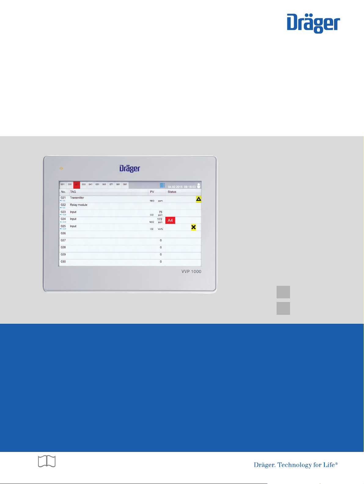
Dräger VVP 1000
Display für die Anbindung an ein Dräger VarioGard System
Display for connection to Dräger VarioGard System
Page 2

Page 3

Inhalt
1 Zu Ihrer Sicherheit . . . . . . . . . . . . . . . . . . . . . . . . .4
1.1 Allgemeine Sicherheitshinweise . . . . . . . . . . . . . . . .4
1.2 Bedeutung der Warnzeichen . . . . . . . . . . . . . . . . . .4
2 Beschreibung . . . . . . . . . . . . . . . . . . . . . . . . . . . . .5
2.1 Produktübersicht . . . . . . . . . . . . . . . . . . . . . . . . . . . .5
2.2 Verwendungszweck . . . . . . . . . . . . . . . . . . . . . . . . .6
2.3 Einschränkungen des Verwendungszwecks . . . . . . .6
3 Zulassungen . . . . . . . . . . . . . . . . . . . . . . . . . . . . . .6
4 Installation . . . . . . . . . . . . . . . . . . . . . . . . . . . . . . . .7
4.1 Mechanische Installation . . . . . . . . . . . . . . . . . . . . . .7
4.2 Elektrische Installation . . . . . . . . . . . . . . . . . . . . . . .8
5 Betrieb . . . . . . . . . . . . . . . . . . . . . . . . . . . . . . . . . .10
5.1 Grundlagen . . . . . . . . . . . . . . . . . . . . . . . . . . . . . . .10
5.2 Touchscreen-Bildschirm . . . . . . . . . . . . . . . . . . . . .11
5.3 Benutzer an- oder abmelden . . . . . . . . . . . . . . . . .11
5.4 Ereignisse anzeigen und quittieren . . . . . . . . . . . . .11
6Menü . . . . . . . . . . . . . . . . . . . . . . . . . . . . . . . . . . . .12
6.1 Bus-Teilnehmer-Detailinformationen anzeigen . . . .12
6.2 Ereignishistorie anzeigen . . . . . . . . . . . . . . . . . . . .12
6.3 System Information anzeigen . . . . . . . . . . . . . . . . .13
6.4 Allgemeine Einstellungen vornehmen . . . . . . . . . . .13
6.5 Netzwerk einstellen . . . . . . . . . . . . . . . . . . . . . . . . .13
6.6 VNC-Servereinstellungen einstellen . . . . . . . . . . . .13
6.7 Modbus-Einstellungen VVP 1000 einstellen . . . . . .14
7 VVP 1000 Datenspeicher . . . . . . . . . . . . . . . . . . .14
8 Störungsbeseitigung . . . . . . . . . . . . . . . . . . . . . .14
9 Instandhaltung . . . . . . . . . . . . . . . . . . . . . . . . . . .14
10 Entsorgung . . . . . . . . . . . . . . . . . . . . . . . . . . . . . .14
11 Technische Daten . . . . . . . . . . . . . . . . . . . . . . . . .15
12 Bestellliste . . . . . . . . . . . . . . . . . . . . . . . . . . . . . . .15
Inhalt
Dräger VVP 1000 3
Page 4
Zu Ihrer Sicherheit
1 Zu Ihrer Sicherheit
1.1 Allgemeine Sicherheitshinweise
Vor Gebrauch des Produkts diese Gebrauchsanweisung
und die der zugehörigen Produkte aufmerksam lesen.
Gebrauchsanweisung genau beachten. Der Anwender
muss die Anweisungen vollständig verstehen und den
Anweisungen genau Folge leisten. Das Produkt darf nur
entsprechend dem Verwendungszweck verwendet
werden.
Gebrauchsanweisung nicht entsorgen. Aufbewahrung und
ordnungsgemäße Verwendung durch die Nutzer
sicherstellen.
Nur geschultes und fachkundiges Personal darf dieses
Produkt verwenden.
Lokale und nationale Richtlinien, die dieses Produkt
betreffen, befolgen.
Nur geschultes und fachkundiges Personal darf das
Produkt überprüfen, reparieren und instand halten. Dräger
empfiehlt, einen Service-Vertrag mit Dräger abzuschließen
und alle Instandhaltungsarbeiten durch Dräger
durchführen zu lassen.
Für Instandhaltungsarbeiten nur Original-Dräger-Teile und
-Zubehör verwenden. Sonst könnte die korrekte Funktion
des Produkts beeinträchtigt werden.
Fehlerhafte oder unvollständige Produkte nicht
verwenden. Keine Änderungen am Produkt vornehmen.
Dräger bei Fehlern oder Ausfällen vom Produkt oder von
Produktteilen informieren.
1.2 Bedeutung der Warnzeichen
Die folgenden Warnzeichen werden in diesem Dokument verwendet, um die zugehörigen Warntexte zu kennzeichnen und
hervorzuheben, die eine erhöhte Aufmerksamkeit seitens des
Anwenders erfordern. Die Bedeutungen der Warnzeichen sind
wie folgt definiert:
GEFAHR
!
Hinweis auf eine unmittelbare Gefahrensituation.
Wenn diese nicht vermieden wird, treten Tod oder
schwere Verletzungen ein.
WARNUNG
!
Hinweis auf eine potenzielle Gefahrensituation.
Wenn diese nicht vermieden wird, können Tod oder
schwere Verletzungen eintreten.
VORSICHT
!
Hinweis auf eine potenzielle Gefahrensituation. Wenn
diese nicht vermieden wird, können Verletzungen oder
Schädigungen am Produkt oder der Umwelt eintreten.
Kann auch als Warnung vor unsachgemäßem Gebrauch verwendet werden.
HINWEIS
i
i
Zusätzliche Information zum Einsatz des Produkts.
Kein Betrieb in explosionsgefährdeten Bereichen
Das Gerät ist nicht für den Betrieb in explosionsgefährdeten
Bereichen zugelassen oder zertifiziert.
4 Dräger VVP 1000
Page 5
2 Beschreibung
VVP 1000
01133547
4
1
6
5
3
7
8
2
+
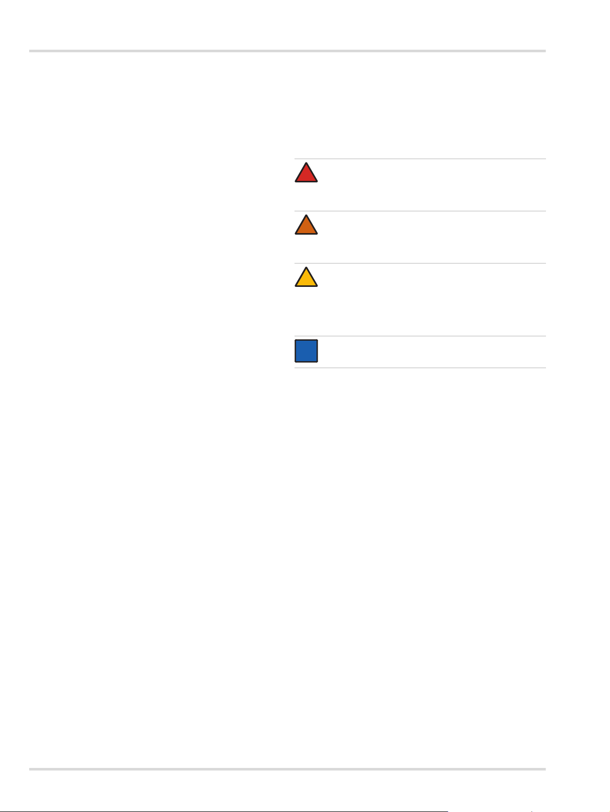
2.1 Produktübersicht
Beschreibung
1 Betriebsanzeige
2 DIP-Schalter und Reset-Taste
3 COM1: RS485 2-/4-Draht, COM3: RS485 2-Draht
4 COM1: RS232
5 Ethernet-Anschluss
6 USB-Anschluss
7 Sicherung
8 Stromanschluss
Dräger VVP 1000 5
Page 6

Zulassungen
2.2 Verwendungszweck
Das Dräger VVP 1000 (nachfolgend Display genannt) ist ein
Display zur grafischen Visualisierung von bis zu 100 Kanälen
aus einem VarioGard-System.
2.3 Einschränkungen des Verwendungszwecks
Das Display ist nicht dafür bestimmt oder zugelassen, in Bereichen zu arbeiten, in denen es zu einer möglichen Entwicklung
von zündfähigen oder explosiblen Gasgemischen kommen
kann.
3 Zulassungen
Sicherheit
IEC 61010-1, EN 61010-1: Sicherheitsbestimmungen für elektrische Komponenten, Teil 1.
IP66 Schutzart-Einstufung (nur Vorderseite), IEC 529
Type 4X Schutzart-Einstufung (nur Vorderseite), UL50
Elektromagnetische Verträglichkeit
Emissionen und Störfestigkeit für EN 61326: Elektrische Betriebsmittel für Leittechnik und Laboreinsatz.
FCC Bedingungen
Dieses Gerät wurde getestet und entspricht Teil 15,
Klasse B der FCC-Bestimmungen. Der Betrieb
unterliegt den beiden folgenden Bedingungen:
(1) Dieses Gerät darf keine schädlichen Störungen
verursachen.
(2) Dieses Gerät muss jede empfangene Störung
akzeptieren und diese beinhalten Störungen, die durch
unerwünschten Betrieb verursacht werden.
Störfestigkeit an Industriestandorten:
Hochfrequenzstörung EN 61000-4-6 Kriterium B
3 V/rms
Überspannung EN 61000-4-5 Kriterium A
1 kV L-L,
2 kV L&N-E-Leistung
Schnelle
Transienten (Burst)
Elektromagnetische
HF-Felder
Elektrostatische
Entladung
Emissionen: EN 55011
EN 61000-4-4 Kriterium A
2 kV Leistung
1 kV Signal
EN 61000-4-3 Kriterium A
10 V/m
EN 61000-4-2 Kriterium A
8 kV Luftentladung
4 kV Kontaktentladung
Klasse A
6 Dräger VVP 1000
Page 7
4 Installation
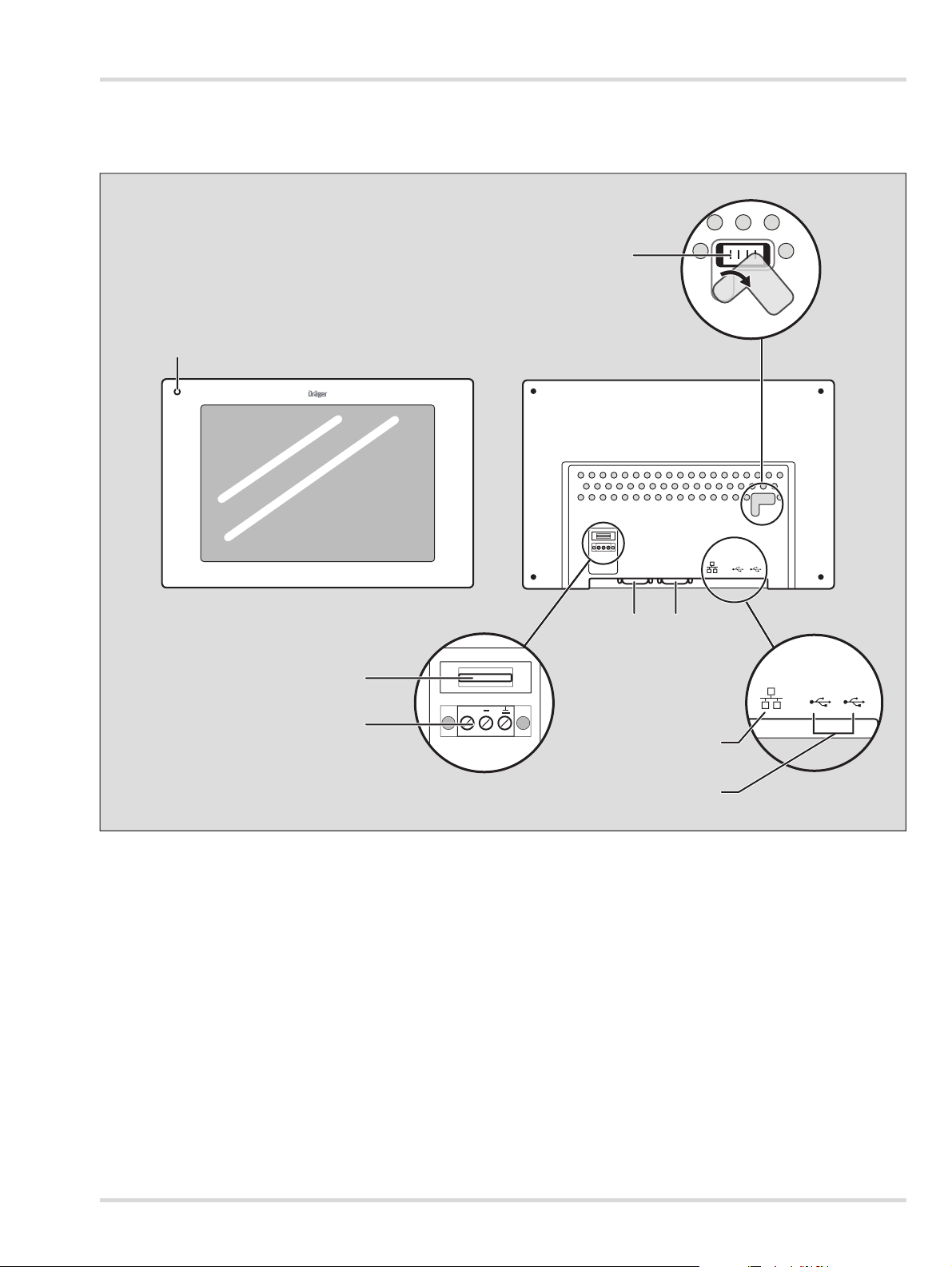
271 mm / 10,66ʺ
258,6 mm / 10,18ʺ
213 mm / 8,38ʺ
200,6 mm / 7,89ʺ
40 mm / 1,57ʺ
9 mm / 0,35ʺ
23,5 mm / 0,92ʺ
7,5 mm / 0,29ʺ
01433547
4.1 Mechanische Installation
Das Display ist für den Einbau in einem Schaltschrank oder einer Schalttafel vorgesehen.
1. Ausschnitt und Bohrungen entsprechend den Einbaumaßen herstellen.
2. Display einsetzen und anschrauben.
Installation
Abmessungen in mm / inch
Alle Tolleranzen ±0,25 mm (±0.010")
Dräger VVP 1000 7
Page 8
Installation
!
A
VarioGardVarioGardVarioGard
VarioGard
VarioGard
VarioGard
VarioGard
VVP 1000
max. 100
5
1
3
4
2
VarioGard VarioGard VarioGard VarioGard
VarioGard VarioGard VarioGard VarioGard
B
max. 50
max. 50
VarioGardVarioGardVarioGard VarioGardVarioGardVarioGard
VVP 1000
1
3
4
5
2
01833547
VarioGard VarioGard VarioGard VarioGard
VarioGard VarioGard VarioGard VarioGard
C
max. 33 max. 33
VarioGard VarioGard VarioGard VarioGard
max. 33
VarioGardVarioGardVarioGard VarioGardVarioGardVarioGardVarioGardVarioGardVarioGard VarioGardVarioGardVarioGard VarioGardVarioGardVarioGard
VVP 1000
3
2
1
4
5
02133547
VarioGardVarioGardVarioGard
VVP 1000
1
2
3
4
5
7
6
8
9
0
1
2
3
4
5
7
6
8
9
0
A
B
GND
x1 x10
01333547
5 4 3 2 1
9 8 7 6
COM1 [RS485]
COM3 [RS485]
4.2 Elektrische Installation
Verlegung und Anschluss der elektrischen Installation dürfen
nur vom Fachmann unter Beachtung der einschlägigen Vorschriften vorgenommen werden. Bei der Leitungsführung die
nationalen Bestimmungen zu Trennung von Netz-, Kleinspannungs- und Steuerstromkreisen beachten (in Deutschland:
VDE-Bestimmungen).
GEFAHR
Stromschlag!
Bei Netzspannung 230 V, 50 Hz im Schaltschrank:
Eine Berührung kann schwere Brandverletzungen verursachen oder zum Tod führen.
Elektrische Anschlüsse nur von einer ausgebildeten
Elektrofachkraft ausführen lassen. Nur im spannungsfreien Zustand montieren!
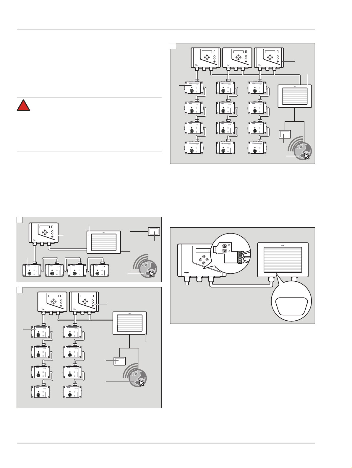
4.2.1 Systemaufbau
An ein Display können je nach Version max. 3 VarioGard Zentralsysteme angeschlossen werden (siehe Kapitel 12 auf
Seite 15). Über eine Remote-Verbindung können mehrere Displays verbunden werden.
Folgende 3 Systemtypen sind möglich:
1 VarioGard Messfühler
2 VarioGard Zentralgerät
3 VVP 1000
4 VVP 1000 Remote
5 Ethernet
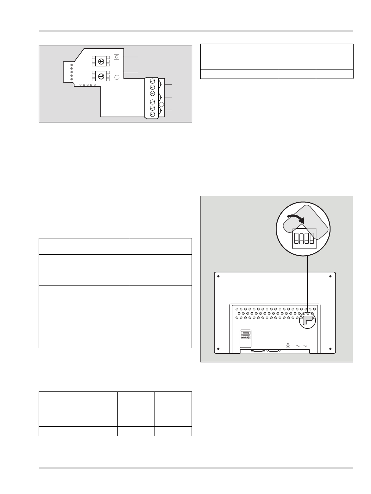
4.2.2 Display mit VarioGard Modbus Gateway verbinden
Um das Display mit dem VarioGard Modbus Gateway zu verbinden:
1. Kabelverbindung Dräger VVP 1000 (COM1/
COM3[RS485]-Buchse) über die Steckkontakte 3 (GND), 4
(B-Modbus-Signal), 5 (A-Modbus-Signal) herstellen.
8 Dräger VVP 1000
Page 9
Installation
1
2
3
4
5
7
6
8
9
0
1
2
3
4
5
7
6
8
9
0
A
B
GND
x1 x10
1
2
3
4
5
02333547.eps
02033547
on
123 4
Dräger VVP 1000
COM1/COM3(RS485)-Buchse
VarioGard
Modbus Gateway
PIN 1 Data- Modbus-Signal B (4)
PIN 2 Data+ Modbus-Signal A (5)
PIN 5 GND GND (3)
2. Mit Dipschalter 1 und 2 die Modbus-Adresse einstellen.
Dipschalter 1 dient für die Einstellung der 1. Stelle der Modbus-Adresse. Dipschalter 2 dient für die Einstellung der 2.
Stelle der Modbus-Adresse.
Die auf dem Modbus-Gateway angebrachte grüne LED zeigt
den aktuellen Status des Modbus-Gateways an.
Schnittstelle
VarioGardZentralgerät
ModbusMaster
Stoppbits 1 1
konfigurierbar Nein Ja
Die Kommunikationsparameter der Modbus-Kommunikation
sind konfigurierbar. Die Baudrate kann auf folgende Werte eingestellt werden:
4800
9600
19200
38400
Die Paritätsprüfung kann auf folgende Status eingestellt werden:
keine
ungerade
gerade
4.2.3 DIP-Switch Einstellungen
Verhalten der LED
Status des ModbusGateways
Blinkt schnell (10 Mal) System startet (neu)
Warten auf
Dauerhaft ausgeschaltet
Datenaktualisierung des
VarioGard-Zentralgeräts
Systeminitialisierung:
Kommunikation
Dauerhaft eingeschaltet
konfigurieren und
statische Informationen
sammeln
Normalbetrieb:
Blinkt regelmäßig in bestimmten
Zeitabständen
Kommunikation mit
VarioGard-Systemen
und Modbus-Master
Kommunikationsschnittstellen
Das Modbus-Gateway enthält 2 voneinander unabhängige
Kommunikationsschnittstellen: Eine zum VarioGard-Zentralgerät und eine zum übergeordneten Modbus-Master.
Schnittstelle
VarioGardZentralgerät
ModbusMaster
Baudrate 9600 19200
Datenbits 8 8
Paritätsbits N N
DIP-Switch Einstellungen
SW1 SW2 SW3 SW4 Mode
ON OFF OFF OFF Touchscreen Calibration Mode
OFF ON OFF OFF Hide HMI System Setting Bar
OFF OFF ON OFF Boot Loader Mode
OFF OFF OFF ON Not supported
OFF OFF OFF OFF Normal
Dräger VVP 1000 9
Page 10

Betrieb
03133026_de.eps
00133547.eps
6
54
3
1
2
5Betrieb
5.1 Grundlagen
5.1.1 Bedien- und Anzeigeelemente
1 Kanalliste Anzeige der 10 Kanäle vom aktiven Kanalbereichregister.
2 Kanalüberschriftenleiste:
No. Anzeige von Busteilnehmertyp und Busadresse (Transmitter/Relaismodul etc.).
TAG Busteilnehmerbezeichnung
PV Messwertanzeige (Messgas/Messwert/Messbereich etc.)
Status Statusanzeige
Störung
Wartung/dringende Wartung
Deaktivierter Busteilnehmer
Ist-Alarm A1 bis A4
Mittelwert-Alarm MA1 bis MA4
3 Kanalbereichregister Die 10 Kanalbereichregister bilden jeweils 10 Kanäle ab.
4
Ereignis-Symbol
5 Menü Die Schaltfläche wählen, um in das Menü zu gelangen.
6
Benutzer an- oder abmelden
Benutzerebenenanzeige
Einlaufphase des Transmitters
Das Ereignis-Symbol wird angezeigt, sobald ein Ereignis an steht (siehe Kapitel 6.1
auf Seite 12).
Die Schaltfläche wählen, um Benutzer an- oder abzumelden.
Im angemeldeten Zustand wird die aktuelle Benutzerebene im Symbol angezeigt.
3 Benutzerebenen stehen zur Verfügung, Konfigurator, Administrator und Service.
10 Dräger VVP 1000
Page 11

Betrieb
i
i
00233547.eps
1
00333547_de.eps
5.2 Touchscreen-Bildschirm
Die Schaltflächen des Touchscreen-Bildschirms verändern
sich dynamisch abhängig von der gerade ausgeführten Aufgabe. Zum Ausführen einer Aktion das entsprechende Symbol
auf dem Display wählen.
5.3 Benutzer an- oder abmelden
Standardmäßig sind folgende Benutzerebenen angelegt:
Benutzer Kennwort
Konfigurator 0001
Administrator 0002
Service XXXX
Um einen Benutzer anzumelden:
1. wählen.
a. auswählen.
b. Gewünschte Benutzerebene aus der Liste auswählen.
2. Kennwort-Eingabefeld wählen.
3. Kennwort eingeben und mit bestätigen.
Um den aktuellen Benutzer abzumelden:
1. wählen.
Informationen zum aktuellen Benutzer werden angezeigt.
2. wählen.
Der aktuelle Benutzer wird abgemeldet.
Folgende Ereignisse werden im Display angezeigt und gespeichert.
Wartung dringend notwendig CHxxx
Wartung notwendig CHxxx
Expositionsalarm CHxxx
Alarm 1 CHxxx
Alarm 2 CHxxx
Alarm 3 CHxxx
Alarm 4 CHxxx
Mittelwertalarm 1 CHxxx
Mittelwertalarm 2 CHxxx
Mittelwertalarm 3 CHxxx
Mittelwertalarm 4 CHxxx
Unterbrechung durch PC CHxxx
Sensor läuft ein CHxxx
Messbereichsüberschreitung CHxxx
Messbereichsunterschreitung CHxxx
Um Ereignisse anzuzeigen:
in der Kopfzeile oder > Ereignisse wählen
Im Ereignisfenster werden die Ereignisse in unterschiedlichen
Farben angezeigt:
HINWEIS
Wenn der Touchscreen für 10 Minuten nicht betätigt
wird, wird der aktuelle Benutzer automatisch abgemeldet.
5.4 Ereignisse anzeigen und quittieren
5.4.1 Ereignisse anzeigen
Sobald ein Ereignis auftritt, wird dies durch das Ereignissymbol in der Kopfzeile angezeigt.
Farbe Bedeutung
Rot Gasalarm
Gelb Störung oder Warnung
Schwarz Statusinformation
Blau Quittierte Meldung
5.4.2 Ereignisse quittieren
Um ein Ereignis zu quittieren:
Gewünschtes Ereignis in der Ereignisliste wählen.
Die quittierte Meldung wird in Blau dargestellt.
Um alle Ereignisse der Ereignisliste und des Zentralgeräts zu
quittieren:
wählen.
Dräger VVP 1000 11
Page 12

Menü
00433547_de.eps
i
i
00533547_de.eps
i
i
6Menü
Je nach Benutzerebene werden unterschiedliche Menüeinträge angezeigt.
Menüeintrag
Einstellungen X X
System Information X X X
Ereignishistorie X X X
Ereignisse X X X
Login X X X
Modbus Server-Einstellungen X
BT-Detailinformationen X X X
BT aktivieren/deaktivieren X X
Netzwerkkonfiguration X
6.1 Bus-Teilnehmer-Detailinformationen an-
Benutzerebene
Wartung
6.2 Ereignishistorie anzeigen
Benutzerebene
Konfigurator
Benutzerebene
Service
zeigen
In der Ereignishistorie kann in den gespeicherten Ereignissen
In der Detailansicht werden alle relevanten Informationen des
Bus-Teilnehmers (BT) angezeigt.
nach Tagesdateien gesucht werden.
Um die Ereignishistorie anzuzeigen:
Um die BT-Detailansicht anzuzeigen:
Gewünschte Transmitterbezeichnung (TAG) in der Stan-
dardansicht wählen.
Das Deaktivieren eines BT ist nur mit besonderen Rechten
möglich.
HINWEIS
Beim VarioGard Konvertermodul Bestellnr. 83 15 226
können die Eingänge nicht deaktiviert werden. In diesem Fall sind die entsprechenden Optionen ausgeblendet.
12 Dräger VVP 1000
> Ereignishistorie wählen.
Um einen Filter einzustellen:
1. Im Bereich Filter setzen das gewünschte Eingabefeld
Jahr, Monat und Tag wählen und den gewünschten Wert
eintragen.
2. Laden wählen.
Wenn eine Datei nicht vorhanden oder beschädigt ist, wird
Fehlgeschlagen angezeigt.
HINWEIS
Ereignisse werden über einen Zeitraum von
365 Tagen auf einem USB-Datenspeicher gesichert.
Eine Speicherung der Daten ist nur bei gestecktem externen USB-Datenspeicher möglich.
Page 13

Menü
00733547_de.eps
00833547_de.eps
00933547_de.eps
01033547_de.eps
6.3 System Information anzeigen
Unter System Information werden alle relevanten Informationen über das aktuelle System angezeigt.
Um einen Screenshot der Systeminformationen zu erstellen:
Bildschirmkopie Speichern (USB) wählen.
Der Screenshot wird auf dem USB-Datenspeicher im Verzeichnis hardcopy gespeichert.
6.5 Netzwerk einstellen
Unter Netzwerk können alle relevanten Netzwerkeinstellungen vorgenommen werden, sowohl manuell als auch automatisch (DHCP).
6.6 VNC-Servereinstellungen einstellen
6.4 Allgemeine Einstellungen vornehmen
Folgende Einstellungen sind möglich:
Sprache
Datums- und Zeiteinstellung
Bildschirmschoneroptionen (aktivieren/deaktivieren/Verzö-
gerungszeit)
Display-Helligkeit
Geräteeinstellungen (Netzwerkkonfiguration und VNC-Cli-
ent-Einstellung)
Starten der Initialisierung
(nötig bei einer Änderung der VarioGard-Konfiguration; bei
einem Neustart des VVP 1000 oder der VarioGard-Zentrale ist dies nicht notwendig)
Bei der VNC (Virtual Network Computing)-Einstellung kann
zwischen single-, multiconnection oder „deaktiviert“ gewählt
werden. Eine Verbindung wird im Menüpunkt System Infor-
mation angezeigt.
Dräger VVP 1000 13
Page 14

VVP 1000 Datenspeicher
00633547_de.eps
i
i
6.7 Modbus-Einstellungen VVP 1000 einstellen
Über die Seite „Modbus Server Einstellungen“ können die seriellen Einstellungen des VVP 1000 überprüft werden.
7 VVP 1000 Datenspeicher
Die Daten, die auf dem USB-Datenspeicher gespeichert werden, sind verschlüsselt. Zum Konvertieren der Daten in ein von
Excel lesbares Format ist der Konverter EasyConverter notwendig. Der Konverter befindet sich auf dem USB-Datenspeicher des Displays.
8 Störungsbeseitigung
Wenn Probleme bei der Installation oder Störungen während
des Betriebs auftreten, DrägerService kontaktieren.
9 Instandhaltung
Das Display regelmäßig (Dräger empfiehlt halbjährlich) von
geschultem und fachkundigen Personal überprüfen lassen.
10 Entsorgung
Dieses Produkt darf nicht als Siedlungsabfall entsorgt
werden. Es ist daher mit dem nebenstehenden Symbol
gekennzeichnet.
Dräger nimmt dieses Produkt kostenlos zurück.
Informationen dazu geben die nationalen
Vertriebsorganisationen und Dräger.
Batterien und Akkus dürfen nicht als Siedlungsabfall
entsorgt werden. Sie sind daher mit dem
nebenstehenden Symbol gekennzeichnet. Batterien
und Akkus gemäß den geltenden Vorschriften bei
Batterie-Sammelstellen entsorgen.
Um die verschlüsselten Daten auf dem USB-Datenspeicher in
ein lesbares Excel-Format zu konvertieren:
1. USB-Datenspeicher aus dem Display entfernen. Der USB-
Datenspeicher kann während des Betriebs entfernt werden.
2. USB-Datenspeicher am PC einstecken.
3. Verzeichnis des USB-Datenspeichers aufrufen.
4. Datei EasyConverter.zip auf den PC kopieren und entpa-
cken.
5. Datei EasyConverter.exe starten
6. Gewünschte Daten des USB-Datenspeichers auswählen
und mit Öffnen bestätigen.
7. In der Menüleiste File > Export to excel wählen um die
Daten speichern.
8. USB-Datenspeicher am PC entfernen und am Display ein-
stecken. Die angezeigte Menüauswahl dient nur für Servicezwecke und kann abgebrochen werden.
HINWEIS
Der USB-Datenspeicher kann am Display während
des Betriebs entfernt und eingesteckt werden.
14 Dräger VVP 1000
Page 15

11 Technische Daten
Anzeige: 10‘‘ TFT LCD Grafik-Anzeige 800x480 Pixel
mit einer Helligkeit von 300 cd/m², 65536
Farben; Kontrastverhältnis: 500:1
Tou ch- Dis play 4-Draht analog resistiv; LED-Hintergrund-
beleuchtung mit einer Lebensdauer von
30.000 Betriebsstunden
USB-Port: 1x USB-2.0-Host
Technische Daten
Serielle Schnittstelle:
Ethernet: 10/100 Base-T mit RJ45-Stecker
Echtzeituhr: Integrierte Echtzeituhr RTC
Schutzart: IP65
Gehäuse: Robustes Kunststoffgehäuse
Schock: 10 bis 25 Hz
Relative Feuchte:10 % bis 90 % r. F., nicht kondensierend
Umgebungstemperatur:
Spannungsversorgung:
Indikatoren: Eine Funktions-LED zeigt die Spannungs-
COM1: RS232/485 2-/4-Draht; RS485Schnittstellen sind MPI-fähig bis
187.500 Baud
(X,Y,Z Richtung 2 g über 30 Minuten)
Betrieb: 0 °C bis +50 °C;
Lager: -20 °C bis +60 °C
24 VDC +-20 %; typ. 400 mA; Anschluss
über steckbare 3-polige Klemmleiste
versorgung an
CPU- und CoreLogik:
Speicher: 128 MB RAM & 128 MB Speicher
32 Bit RISC 600 MHz Prozessor;
Linuxbasiertes Betriebssystem
12 Bestellliste
Bezeichnung Bestellnr.
Dräger VVP 1000 (1x VarioGard System mit bis
zu 100 Busteilnehmern)
Dräger VVP 1000 (2x VarioGard System mit jeweils bis zu 50 Busteilnehmern)
Dräger VVP 1000 (3x VarioGard System mit jeweils bis zu 33 Busteilnehmern)
Dräger VarioGard-Modbus-Gateway 83 24 834
Dräger VVP 1000 15
83 25 681
83 25 682
83 25 683
Page 16

Bestellliste
16 Dräger VVP 1000
Page 17

Contents
1 For your safety . . . . . . . . . . . . . . . . . . . . . . . . . . .18
1.1 General safety notes . . . . . . . . . . . . . . . . . . . . . . . .18
1.2 Definitions of Alert Icons . . . . . . . . . . . . . . . . . . . . .18
2 Description . . . . . . . . . . . . . . . . . . . . . . . . . . . . . .19
2.1 Product Overview . . . . . . . . . . . . . . . . . . . . . . . . . .19
2.2 Intended Use . . . . . . . . . . . . . . . . . . . . . . . . . . . . . .20
2.3 Limitations on use . . . . . . . . . . . . . . . . . . . . . . . . . .20
3 Approvals . . . . . . . . . . . . . . . . . . . . . . . . . . . . . . .20
4 Installation . . . . . . . . . . . . . . . . . . . . . . . . . . . . . . .21
4.1 Mechanical installation . . . . . . . . . . . . . . . . . . . . . .21
4.2 Electrical installation . . . . . . . . . . . . . . . . . . . . . . . .22
5 Operational characteristics . . . . . . . . . . . . . . . . .24
5.1 Basics . . . . . . . . . . . . . . . . . . . . . . . . . . . . . . . . . . .24
5.2 Touchscreen display . . . . . . . . . . . . . . . . . . . . . . . .25
5.3 Log user in or out . . . . . . . . . . . . . . . . . . . . . . . . . .25
5.4 Viewing and acknowledging events . . . . . . . . . . . .25
6Menu . . . . . . . . . . . . . . . . . . . . . . . . . . . . . . . . . . . .26
6.1 Viewing detailed information on bus devices . . . . .26
6.2 Viewing the Event History . . . . . . . . . . . . . . . . . . . .26
6.3 Viewing system information . . . . . . . . . . . . . . . . . .27
6.4 Defining general settings . . . . . . . . . . . . . . . . . . . .27
6.5 Defining network settings . . . . . . . . . . . . . . . . . . . .27
6.6 Defining the VNC server settings . . . . . . . . . . . . . .27
6.7 Defining VVP 1000 Modbus settings . . . . . . . . . . .28
7 VVP 1000 storage medium . . . . . . . . . . . . . . . . . .28
8 Troubleshooting . . . . . . . . . . . . . . . . . . . . . . . . . .28
9 Maintenance . . . . . . . . . . . . . . . . . . . . . . . . . . . . .28
10 Disposal . . . . . . . . . . . . . . . . . . . . . . . . . . . . . . . . .28
11 Technical Data . . . . . . . . . . . . . . . . . . . . . . . . . . . .29
12 Order list . . . . . . . . . . . . . . . . . . . . . . . . . . . . . . . .29
Contents
Dräger VVP 1000 17
Page 18

For your safety
1 For your safety
1.1 General safety notes
Before using this product, carefully read these Instructions
for Use and those of the associated products.
Strictly follow the Instructions for Use. The user must fully
understand and strictly observe the instructions. Use the
product only for the purposes specified in the Intended use
section of this document.
Do not dispose of the Instructions for Use. Ensure that they
are retained and appropriately used by the product user.
Only trained and competent users are permitted to use this
product.
Comply with all local and national rules and regulations
associated with this product.
Only trained and competent personnel are permitted to
inspect, repair and service the product. Dräger recommend
a Dräger service contract for all maintenance activities and
that all repairs are carried out by Dräger.
Use only genuine Dräger spare parts and accessories, or
the proper functioning of the product may be impaired.
Do not use a faulty or incomplete product. Do not modify
the product.
Notify Dräger in the event of any component fault or failure.
Do not operate in potentially explosive areas
This device is neither approved nor certified for use in areas
where combustible or explosive gas mixtures are likely to occur.
1.2 Definitions of Alert Icons
The following alert icons are used in this document to provide
and highlight areas of the associated text that require a greater
awareness by the user. A definition of the meaning of each
icon is as follows:
DANGER
!
Indication of an imminently hazardous situation. If this
is not avoided, death or serious injury will result.
WARNING
!
Indicates a potentially hazardous situation
if not avoided, could result in death or serious injury.
CAUTION
!
Indicates a potentially hazardous situation which, if not
avoided, could result in physical injury, or damage to
the product or environment. It may also be used to
alert against unsafe practices.
NOTICE
i
i
Indicates additional information on how to use the
product.
18 Dräger VVP 1000
Page 19

2 Description
VVP 1000
01133547
4
1
6
5
3
7
8
2
+
2.1 Product Overview
Description
1LED
2 DIP switch and Reset button
3 COM1: RS485 2-/4-wire, COM3: RS485 2-wire
4 COM1: RS232
5 Ethernet port
6 USB connection
7Fuse
8 Mains connection
Dräger VVP 1000 19
Page 20

Approvals
2.2 Intended Use
The Dräger VVP 1000 (hereafter referred to as "display") is a
display for the graphical visualisation of up to 100 channels of
a VarioGard system.
2.3 Limitations on use
The display is not designed or authorised for use in areas
where flammable or explosive gas mixtures could develop.
3Approvals
Safety
IEC 61010-1, EN 61010-1: Safety requirements for electrical
components, Part 1.
IP66 degree of protection classification (front only), IEC 529
Type 4X degree of protection classification (front only), UL50
Electromagnetic compatibility
Emissions and immunity for EN 61326: Electrical equipment
for measurement, control and laboratory use.
Immunity to industrial locations:
RF interference EN 61000-4-6 Criterion B
3V/rms
FCC conditions
This device has been tested and complies with Part 15,
Class B of the FCC conditions. Its operation is subject
to the following conditions:
(1) This device must not cause harmful interference.
(2) This device must accept any received interference;
this includes interference caused by unintentional
operation.
Surge voltage EN 61000-4-5 Criterion A
1 kV L-L,
2 kV L&N-E power
Fast transients (burst) EN 61000-4-4 Criterion A
2 kV power
1 kV signal
Power frequency
magnetic fields
Electrostatic
discharge
Emissions: EN 55011
EN 61000-4-3 Criterion A
10 V/m
EN 61000-4-2 Criterion A
8 kV air discharge
4 kV contact discharge
Class A
20 Dräger VVP 1000
Page 21

4 Installation
271 mm / 10,66ʺ
258,6 mm / 10,18ʺ
213 mm / 8,38ʺ
200,6 mm / 7,89ʺ
40 mm / 1,57ʺ
9 mm / 0,35ʺ
23,5 mm / 0,92ʺ
7,5 mm / 0,29ʺ
01433547
4.1 Mechanical installation
The display is designed for integration into a cabinet or
switchboard.
1. Make cuts and holes in accordance with the installation
dimensions.
2. Insert the display and screw it tight.
Installation
Dimensions in mm / inches
All tolerances ±0.25 mm (±0.010")
Dräger VVP 1000 21
Page 22

Installation
!
A
VarioGardVarioGardVarioGard
VarioGard
VarioGard
VarioGard
VarioGard
VVP 1000
max. 100
5
1
3
4
2
VarioGard VarioGard VarioGard VarioGard
VarioGard VarioGard VarioGard VarioGard
B
max. 50
max. 50
VarioGardVarioGardVarioGard VarioGardVarioGardVarioGard
VVP 1000
1
3
4
5
2
01833547
VarioGard VarioGard VarioGard VarioGard
VarioGard VarioGard VarioGard VarioGard
C
max. 33 max. 33
VarioGard VarioGard VarioGard VarioGard
max. 33
VarioGardVarioGardVarioGard VarioGardVarioGardVarioGardVarioGardVarioGardVarioGard VarioGardVarioGardVarioGard VarioGardVarioGardVarioGard
VVP 1000
3
2
1
4
5
02133547
VarioGardVarioGardVarioGard
VVP 1000
1
2
3
4
5
7
6
8
9
0
1
2
3
4
5
7
6
8
9
0
A
B
GND
x1 x10
01333547
5 4 3 2 1
9 8 7 6
COM1 [RS485]
COM3 [RS485]
4.2 Electrical installation
The electrics must only be laid and connected by a specialist
and whilst observing the relevant directives. When laying the
cables, the national directives concerning the disconnection
from the mains, low voltage and control voltage supplies must
be observed (in Germany: VDE provisions).
DANGER
Electric shock!
With mains voltage (230 V, 50 Hz) in the cabinet:
A simple touch could cause severe burns or death.
Have the electrics connected only by an experienced
electrician. Make sure the voltage is switched off
before installation!
4.2.1 System setup
Up to three VarioGard control units can be connected to one
display (see Section 12 on page 29). Multiple displays can be
interconnected via a remote connection.
The following three system types are possible:
1 VarioGard transmitter
2 VarioGard control unit
3 VVP 1000
4 VVP 1000 Remote
5 Ethernet
4.2.2 Connecting the display to the VarioGard Modbus gateway
To connect the display to the VarioGard Modbus gateway:
1. Establish cable connection to the Dräger VVP 1000
(COM1/COM3[RS485] port) using plug contacts 3 (GND),
4 (Modbus signal B) and 5 (Modbus signal A).
22 Dräger VVP 1000
Page 23

Installation
1
2
3
4
5
7
6
8
9
0
1
2
3
4
5
7
6
8
9
0
A
B
GND
x1 x10
1
2
3
4
5
02333547.eps
02033547
on
123 4
Dräger VVP 1000
COM1/COM3(RS485) port
VarioGard
Modbus gateway
PIN 1 data- Modbus signal B (4)
PIN 2 data+ Modbus signal A (5)
PIN 5 GND GND (3)
2. Set the Modbus address using DIP switches 1 and 2. DIP
switch 1 is used to set the first character of the Modbus
address. DIP switch 2 is used to set the second character
of the Modbus address.
The green LED on the Modbus gateway indicates the current
status of the Modbus gateway.
Interface
VarioGard
control unit
Modbus
master
Stop bits 1 1
Configurable No Yes
The communication parameters for the Modbus communication
can be configured. The baud rate can be set to the following
values:
4800
9600
19200
38400
The parity check can be set to the following values:
none
odd
even
4.2.3 DIP switch settings
Behaviour of the LED
Flashes rapidly (10 times)
Status of the Modbus
gateway
System starting
(restarting)
Waiting for a data
Permanently off
update from the
VarioGard control unit
System initialisation:
Permanently on
configuring
communication and
collecting static data
Normal operation:
Flashes regularly at constant
intervals
communicating with
VarioGard systems and
Modbus master
Communication interfaces
The Modbus gateway contains two mutually independent
communication interfaces: one to the VarioGard control unit
and one to the higher-level Modbus master.
Interface
VarioGard
control unit
Modbus
master
Baud rate 9600 19200
Data bits 8 8
Parity bits N N
DIP switch settings
SW1 SW2 SW3 SW4 Mode
ON OFF OFF OFF Touchscreen calibration mode
OFF ON OFF OFF Hide HMI system setting bar
OFF OFF ON OFF Boot loader mode
OFF OFF OFF ON Not supported
OFF OFF OFF OFF Normal
Dräger VVP 1000 23
Page 24

Operational characteristics
03133026_de.eps
00133547.eps
6
54
3
1
2
5 Operational characteristics
5.1 Basics
5.1.1 Operating and display elements
1 List of channels List of the 10 channels from the active channel range register.
2 Channel header bar:
No. Display of the bus device and bus address (transmitter/ relay module, etc.)
TAG Bus device designation
PV Display of measured values (measured gas/measured value/measuring range, etc.)
Status Status display
Fault
Maintenance/urgent maintenance
Deactivated bus device
Actual alarm A1 to A4
Average alarms MA1 to MA4
3 Channel range register Each of the 10 channel range registers shows 10 channels.
4 Event symbol The event symbol appears when an event is pending (see Section 6.1 on page 26).
5 Menu Select this button to access the menu.
6
Log user in or out
User level display
Transmitter warm-up phase
Select this button to log users in or out.
When a user is logged in, the current user level is displayed in the icon.
Three user levels are available: Configurator, Administrator and Service.
24 Dräger VVP 1000
Page 25

Operational characteristics
i
i
00233547.eps
1
00333547_en.eps
5.2 Touchscreen display
The buttons on the touchscreen display change dynamically
depending on the task being executed. To execute an action,
select the corresponding icon on the display.
5.3 Log user in or out
The following user levels are set up by default:
User Password
Configurator 0001
Administrator 0002
Service XXXX
To log in a user:
1. Select .
a. Select .
b. Select the desired user level from the list.
2. Select the password input field.
3. Enter the password and confirm with .
To log out the current user:
1. Select .
Information about the current user will be displayed.
2. Select .
The current user will be logged out.
The following events are displayed and saved:
Maintenance urgently needed CHxxx
Maintenance necessary CHxxx
Exposure alarm CHxxx
Alarm 1 CHxxx
Alarm 2 CHxxx
Alarm 3 CHxxx
Alarm 4 CHxxx
Average alarm 1 CHxxx
Average alarm 2 CHxxx
Average alarm 3 CHxxx
Average alarm 4 CHxxx
Interruption due to PC CHxxx
Sensor warming up CHxxx
Over range CHxxx
Under range CHxxx
To display events:
Select in the header or select > Events
The Events screen shows the events in different colours:
NOTICE
If the touchscreen is not operated for 10 minutes, the
current user will be logged out automatically.
5.4 Viewing and acknowledging events
5.4.1 Viewing events
When an event occurs, this is indicated by the event symbol in
the header.
Colour Meaning
Red Gas alarm
Yellow Fault or warning
Black Status information
Blue Acknowledged message
5.4.2 Acknowledging events
To acknowledge an event:
Select the desired event from the Events list.
The acknowledged message turns blue.
To acknowledge all events of the Events list and the control unit:
Select .
Dräger VVP 1000 25
Page 26

Menu
00433547_en.eps
i
i
00533547_en.eps
6Menu
The menu entries displayed depend on the user level.
Menu entry
Settings XX
System Information X X X
Event History XXX
Events XXX
Login X X X
Modbus server settings X
BD detailed information X X X
Activate/deactivate BD X X
Network Configuration X
6.1 Viewing detailed information on bus devices
The detailed view displays all relevant bus device (BD) data.
Maintenance
user level
6.2 Viewing the Event History
In the Event History, users can search the stored events for
day files.
User level
Configurator
User level
Service
To view the BD detailed information:
Select the desired transmitter designation (TAG) in the
standard view.
Deactivating a BD is only possible with special rights.
NOTICE
The inputs for the VarioGard converter module with
order no. 83 15 226 cannot be deactivated. In this
case, the relevant options are not displayed.
26 Dräger VVP 1000
To view the Event History:
> Select Event History.
To set a filter:
1. In the Set filter area, select the desired input field for the
Year, Month and Day and enter the desired value.
2. Select Load.
If a file does not exist or is damaged, Failed appears.
NOTICE
i
i
Events are stored on a USB storage medium for a
period of 365 days. Storage is only possible if an
external USB storage medium is connected.
Page 27

Menu
00733547_en.eps
00833547_en.eps
00933547_en.eps
01033547_en.eps
6.3 Viewing system information
The System Information screen displays all relevant
information for the current system.
To take a screenshot of the system information:
Select Screen capture storage (USB).
The screenshot will be saved to the hardcopy folder on the
USB storage medium.
6.5 Defining network settings
In the Network screen, the user can define all relevant network
settings, either manually or automatically (DHCP).
6.6 Defining the VNC server settings
6.4 Defining general settings
The following settings are possible:
Language
Date and time
Screensaver options (activate/deactivate/delay time)
Display brightness
Device settings (network configuration and VNC client
setting)
Starting initialisation
(required for changing the VarioGard configuration; not
required for restarting the VVP 1000 or the VarioGard
control unit)
The VNC (Virtual Network Computing) setting options are
single-connection, multi-connection and "deactivated". A
connection is shown in the System Information menu item.
Dräger VVP 1000 27
Page 28

VVP 1000 storage medium
00633547_en.eps
i
i
6.7 Defining VVP 1000 Modbus settings
On the "Modbus server settings" page, the user can check the
serial settings of the VVP 1000.
7 VVP 1000 storage medium
The data saved to the USB storage medium is encrypted. The
data can be converted to an Excel-readable format with
EasyConverter. The converter is located on the USB storage
medium of the display.
8 Troubleshooting
If problems or faults occur during installation or operation,
contact DrägerService.
9 Maintenance
Have the display checked by trained experts on a regular basis
(Dräger recommends every six months).
10 Disposal
This product must not be disposed of as municipal
waste. This is indicated by the adjacent icon.
You can return this product to Dräger free of charge.
For information please contact the national sales
organisations and Dräger.
Batteries and rechargeable batteries must not be
disposed of as municipal waste. This is indicated by
the adjacent icon. Collect and dispose of batteries and
rechargeable batteries at battery collection centres, in
accordance with applicable regulations.
To convert the encrypted data on the USB storage medium to
an Excel-readable format:
1. Remove the USB storage medium from the display. The
USB storage medium can be removed during operation.
2. Connect the USB storage medium to the PC.
3. Open the directory of the USB storage medium.
4. Copy the EasyConverter.zip file to the PC and unzip it.
5. Start the EasyConverter.exe file.
6. Select the desired data on the USB storage medium and
then select Open.
7. Select File > Export to excel to save the data.
8. Remove the USB storage medium from the PC and
connect it to the display. The menu selection displayed is
only for service purposes and can be cancelled.
NOTICE
The USB storage medium can be removed from and
connected to the display during operation.
28 Dräger VVP 1000
Page 29

11 Technical Data
Display: 10‘‘ TFT LCD graphic display, 800x480
pixels, with a brightness of 300 cd/m²,
65536 colours; contrast ratio: 500:1
Touch display 4-wire analogue resistive; LED backlight
with a life time of 30,000 operating hours
USB port: 1x USB 2.0 host
Serial port: COM1: RS232/485 2-/4-wire; RS485
interfaces support MPI up to 187,500 bauds
Ethernet: 10/100 Base-T with RJ45 connector
Real time clock: Integrated real time clock (RTC)
Protection class: IP65
Housing: Robust plastic housing
Technical Data
Shock: 10 to 25 Hz
Relative
humidity:
Ambient
temperature:
Power supply: 24 VDC +-20 %; typ. 400 mA; connection
Indicators: A function LED indicates power supply
CPU and core
logic:
Memory: 128 MB RAM & 128 MB memory
(X, Y, Z direction 2 g for 30 minutes)
10 % to 90 % r. h., non-condensing
Operation: 0 °C to +50 °C;
Storage: -20 °C to +60 °C
via 3-pin plug-in terminal strip
32-bit RISC 600 MHz processor;
Linux-based operating system
12 Order list
Name Order no.
Dräger VVP 1000 (1x VarioGard system with up
to 100 bus devices)
Dräger VVP 1000 (2x VarioGard system with up
to 50 bus devices each)
Dräger VVP 1000 (3x VarioGard system with up
to 33 bus devices each)
Dräger VarioGard Modbus gateway 83 24 834
83 25 681
83 25 682
83 25 683
Dräger VVP 1000 29
Page 30

Order list
30 Dräger VVP 1000
Page 31

Page 32

Dräger Safety AG & Co. KGaA
Revalstraße 1
D-23560 Lübeck
Germany
Tel +49 451 882 0
Fax +49 451 882 20 80
www.draeger.com
90 33 547 - TH 4675.920
© Dräger Safety AG & Co. KGaA
Edition 01 - June 2015
Subject to alteration
 Loading...