

Page 1

RETURN TO CD-ROM TABLE OF CONTENTS
North
American
Vitalert3000ServiceManualTableofContents
Dräger
Summary of what's new in Revision L
DESCRIPTION PAGE
SECTION1:
Introduction........................................................1-1
SECTION2:
Diagnostics.........................................................2-1
2.1 MainServiceScreen........................................2-2
2.2 PMSSchedule............................................2-3
2.3 Monitors................................................2-4
2.4 Keys....................................................2-8
2.5 SecondaryServiceScreens...................................2-9
SECTION3:
Troubleshooting......................................................3-1
3.1 PowerSupplyandVoltageDistribution.........................3-1
3.2 TroubleshootingGuides.....................................3-2
SECTION4:
ReplacementProcedures...............................................4-1
4.1 VITALERT3000Cover.....................................4-2
4.2 ProcessorAssembly........................................4-4
4.3 PowerSupply.............................................4-7
4.4 FrontBezelAssembly......................................4-9
4.5 SpO
Assembly...........................................4-11
2
4.6 NIBPModule............................................4-13
4.7 GasAnalyzerAssembly....................................4-15
4.8 SamplePump............................................4-17
4.9 Firmware...............................................4-19
SECTION5:
AdjustmentandCalibrationProcedures...................................5-1
5.1 SpO
MonitorCalibrationCheck..............................5-2
2
5.2 NIBPCuffInflationPressureCheck...........................5-4
5.3 GasSampleLineFlowCalibration.............................5-6
5.4 GasAnalyzerSpanCalibration...............................5-8
5.5 TiltBezelFrictionAdjustment...............................5-11
SECTION6:
PMSProcedure......................................................6-1
6.1 SafetyandElectricalTesting.................................6-2
6.2 ServiceScreen............................................6-3
6.3 SpO
/Pulse...............................................6-4
2
6.4 NIBP...................................................6-5
6.5 CO
/SampleLine..........................................6-6
2
6.6 AlarmCircuitDelayTest....................................6-8
Rev.H
i
Page 2

RETURN TO THIS MANUAL’S TABLE OF CONTENTS
RETURN TO CD-ROM TABLE OF CONTENTS
CONTENTS (continued) VA3000
DESCRIPTION PAGE
6.7 System Configuration ............................................ 6-8
6.8 Reset/PMS Criteria ............................................. 6-9
6.9 Accessory Attachments ...................................... 6-9
6.10 Visual Inspection .......................................... 6-9
6.11 Operator Manual .......................................... 6-9
SECTION 7:
Spare and Replacement Parts
ASSEMBLY/PART PAGE
Cabinet Assembly (Cover), Water Trap & Air Filter ...................... 7-2, 7-3
Front Bezel and Related Items ...................................... 7-4, 7-5
NIBP Pump, Bracket, Interface Panel ................................. 7-6, 7-7
Assembly (incl. Bracket and Modules), Interface Panel ................ 7-8, 7-9
SpO
2
Processor Assembly, Speakers, Mains Filter, Circuit Breaker ..............7-10, 7-11
Gas Analyzer Assembly and Sample Pump ............................7-12, 7-13
Power Supply, Input and Output Wire Harnesses,
Touch-up paint: Euro white, Euro blue ..........................7-14, 7-15
ii
Rev. L
Page 3

RETURN TO THIS MANUAL’S TABLE OF CONTENTS
RETURN TO CD-ROM TABLE OF CONTENTS
Page 4
RETURN TO THIS MANUAL’S TABLE OF CONTENTS
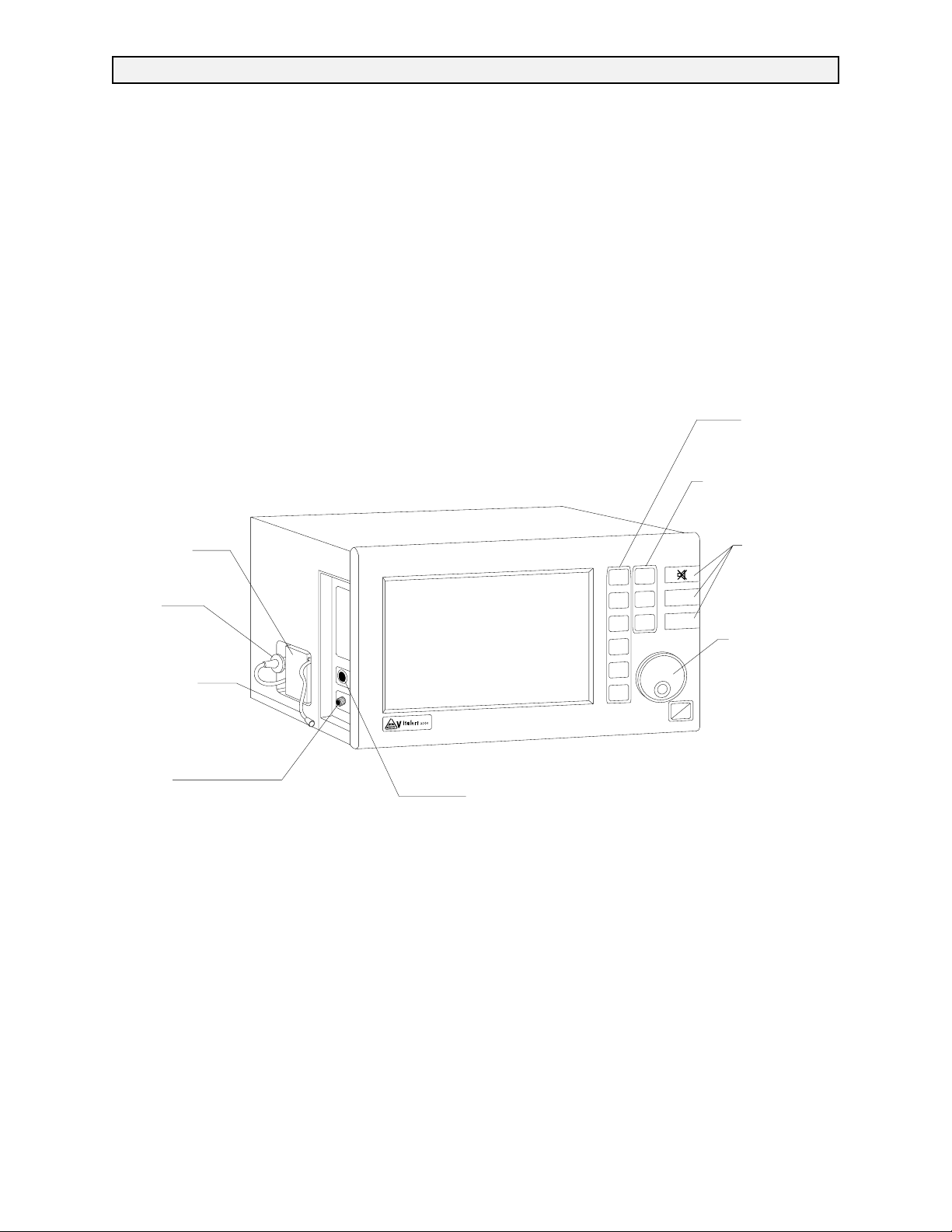
VITALERT 3000 SERIES MONITORING SYSTEM
RETURN TO CD-ROM TABLE OF CONTENTS
MAIN KEY
PANEL
WATER
TRAP
AIR
FILTER
SAMPLE
LINE
NIBP
INTERFACE
PANEL
PULSE OXIMETE R
INTERFACE PANEL
MONITOR
ALARM
LIMITS
MONITOR
SETUP
SYSTEM
CONFIG
DATA
ALARMS
STBY
NIBP CONTROL
KEYS
CONTROL
NIBP
START
LOG
NIBP
DATA
STOP
NIBP
AUTOSET
STAT
KEYS
SELECTION
DIAL
LOG
ON
STBY
SV30123
1-0 Rev. C
Page 5

RETURN TO THIS MANUAL’S TABLE OF CONTENTS
RETURN TO CD-ROM TABLE OF CONTENTS
VA3000 INTRODUCTION
1.0 Recommendations
Because of the sophisticated nature of Draeger Medical, Inc. monitoring equipment and its critical
importance in the operating room setting, it is highly recommended that only appropriately
trained and experienced professionals be permitted to service and maintain this equipment.
Please contact DrägerService at (800) 543-5047 for service of this equipment.
Draeger Medical, Inc. also recommends that its monitoring equipment be serviced at three-month
intervals. Periodic Manufacturer’s Service Agreements are available for equipment manufactured
by Draeger Medical, Inc.. For further information concerning these agreements, please contact
us at (800) 543-5047.
Draeger Medical, Inc. products/material in need of factory repair shall be sent to:
DrägerService
3124 Commerce Drive
Telford, PA 18969
(Include RMA Number)
HOW TO USE THIS MANUAL
The manual is divided into several sections. The DIAGNOSTICS section describes self-test and
service diagnostics for checking the system functions. An understanding of the on-board service
capabilities is necessary before any attempt is made to troubleshoot the unit. The
TROUBLESHOOTING section provides troubleshooting guides to assist the TSR in locating the
source of a problem. The REPLACEMENT PROCEDURES section contains instructions for
removal and replacement of the assemblies that are considered field-replaceable. The
ADJUSTMENT AND CALIBRATION PROCEDURES section contains the field procedures needed
to restore original system specifications. The Periodic Manufacturer’s Service (PMS)
PROCEDURE section outlines the steps required to verify the electrical, mechanical and
pneumatic safety of the unit and also identifies components requiring periodic replacement.
GENERAL TROUBLESHOOTING GUIDELINES
Troubleshooting the VITALERT 3000 should always begin by communicating with those who
observed or experienced the problem with the unit. This may eliminate unnecessary
troubleshooting steps. Once a general problem is identified, refer to the troubleshooting flow
charts in Section 3 of this manual to determine proper corrective action.
After a component is replaced, verify that the unit is operating properly by running the
appropriate diagnostic procedure. The PMS PROCEDURE in Section 6 must also be performed
after any component has been replaced, removed, calibrated or adjusted.
The general arrangement of a VITALERT 3200 Monitor is shown on the opposite page.
WARNINGS are used in this manual before procedures which if not performed correctly could
result in personal injury.
CAUTIONS are used in this manual to alert service personnel to the possibility of damage to the
equipment if a procedure is not performed correctly.
EQUIPMENT CLASS: IEC 601 Class 1, Type BF, continuous
Rev. H
1-1
Page 6

RETURN TO THIS MANUAL’S TABLE OF CONTENTS
RETURN TO CD-ROM TABLE OF CONTENTS
INTRODUCTION (continued) VA3000
Copyright
Copyright © 1999 by Draeger Medical, Inc. All rights reserved. No part of this publication
may be reproduced, transmitted, transcribed, or stored in a retrieval system in any form or
by any means, electronic or mechanical, including photocopying and recording, without the
written permission of Draeger Medical, Inc.
Trademark Notices
CliniDAS, Datagrip, NAD Information Systems, NAD Logo, Narkomed, O.R. Data Manager,
O.R. Link, ORM, PC Prep/View, Quality Service For Life, Vigilance Audit, Vitalert, and
Vitalink are registered trademarks of Draeger Medical, Inc. Trademark application has been
made for NMGS and registration is pending. All other products or name brands are
trademarks of their respective owners.
Disclaimer
The content of this manual is furnished for informational use only and is subject to change
without notice. Draeger Medical, Inc. assumes no responsibility or liability for any errors or
inaccuracies that may appear in this manual.
1-2
Rev. H
Page 7

RETURN TO THIS MANUAL’S TABLE OF CONTENTS
RETURN TO CD-ROM TABLE OF CONTENTS
VA3000 DIAGNOSTICS
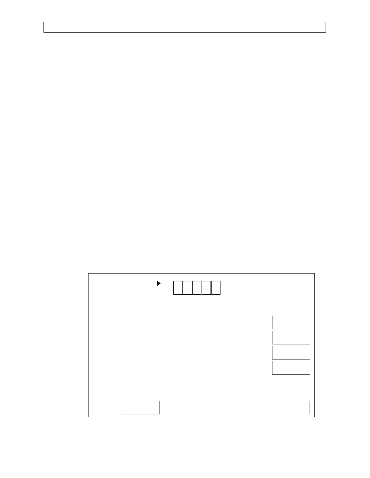
2.0 DIAGNOSTICS
The VITALERT 3000 Series contains a diagnostic system that monitors certain system
functions and records their operational status. A series of tests is performed when the
instrument is powered up and the results are displayed on the diagnostics screen shown in
Figure 2-1. If any of these tests fail, consult Section 3 for proper corrective action.
The operational status of the VITALERT 3000 Series is shown at the end of the power-up
self-diagnostics and will be one of the following:
FUNCTIONAL: All self-diagnostic tests pass, and the instrument begins normal
monitoring operation.
CONDITIONALLY A non-critical fault has been detected, and the MONITOR key
FUNCTIONAL must be pressed to continue operation. The instrument may
continue to be used in this situation, but steps shall be taken to
eliminate the problem.
NON-FUNCTIONAL: The self-diagnostic tests reveal a problem in the instrument. A
summary of the diagnostic results is posted and normal
operation is inhibited. The instrument cannot be operated until
the problem is corrected.
Further diagnostic functions are available through service screens that can be accessed as
described on the following pages. If no display is present upon system power-up, refer to
Section 3 of this manual for troubleshooting assistance.
DIAGNOSTIC TESTS
FIRMWARE
VIDEO
MEMORY
TIMER
AUDIO - PRI MARY
BACK UP
SpO2
SERIAL I/O
CLOCK
NVRAM
PASS
PASS
PASS
PASS
PASS
PASS
PASS
PASS
PASS
PASS
VITALERT 3000
COPYRIGHT 1993, NAD INC.
VERSION 1.03
Rev. H
FUNCTIONAL
SV30101
Figure 2-1: POWER-UP DIAGNOSTICS SCREEN
2-1
Page 8

SYSTEM CONFIG
MONITOR
3
MAIN
PMS
SCHEDULE
MONITORS
KEYS
SERVICE
RESET
HOURS
ROTATE DIAL TO MOVE CURSOR
PRESS TO ACTIVATE FEATURE
3 3 3
SV30104
MACHINE SERIAL NUMBER
LAST SERVICE DATE
HOURS RUN SINCE LAST SERVICE
TOTAL HOURS RUN
VA3:14900
07-14-93
97
3383
OXIM SW VERSION:
GAI SW VERSION:
GAS BENCH SW VERSION:
V 1.0.7
V 1.2.3
V 1.0.1
SERVICE PERSON
IDENTIFICATION
SERVICE TYPE
RETURN TO THIS MANUAL’S TABLE OF CONTENTS
RETURN TO CD-ROM TABLE OF CONTENTS
DIAGNOSTICS (continued) VA3000
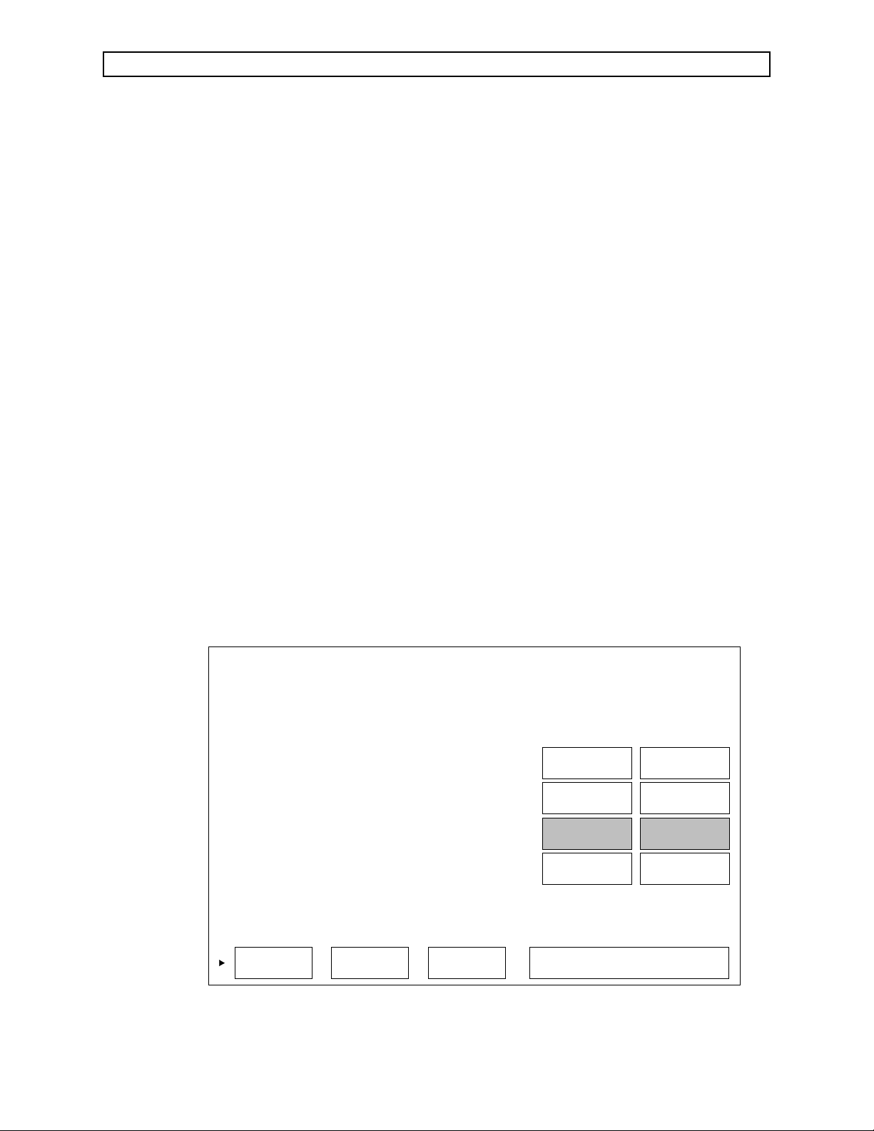
2.1 Main Service Screen
The VITALERT 3000 Series monitors include a maintenance mode that allows
the setting of gas sample flow rates, gas analyzer calibration, diagnostic testing
of the NIBP and SpO
monitors. A Preventive Maintenance Schedule (PMS)
2
screen is also provided for setting the next PMS due date. These maintenance
functions are represented by a series of screens described on following pages,
that can be accessed from the Main Service Screen shown in Figure 2-2. In
addition to these functions, a series of Secondary Service screens allows
viewing of the machine’s service log and making service entries.
The Main Service Screen displays the serial number, the date that the
instrument was last serviced, the hours since last service, total hours on the
instrument and the version number for each software set in the instrument.
To access the Main Service Screen, simultaneously press and hold the
MONITOR
and keys. While holding the keys, press the rotary dial.
With the rotary dial, set the cursor to the Service Person Identification box and
press the dial. Scroll to the first character of your Service I.D., then enter the
selection by pressing the dial. Enter the three remaining I.D. characters in the
same manner.
Use the rotary dial to select the service screens described in the following
paragraphs. Selecting RESET and pressing the dial will set the last service
date to the current date, and the hours run since last service to zero. Pressing
the key on the front panel will return the instrument to normal
operation.
Figure 2-2: MAIN SERVICE SCREEN
2-2
Page 9
RETURN TO THIS MANUAL’S TABLE OF CONTENTS
RETURN TO CD-ROM TABLE OF CONTENTS
VA3000 DIAGNOSTICS (continued)
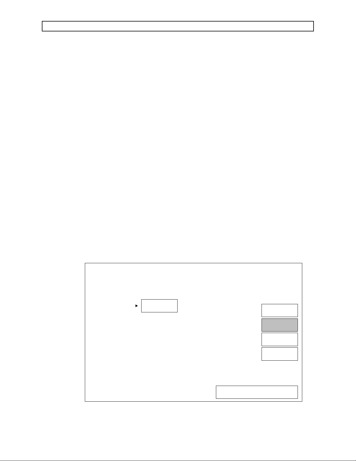
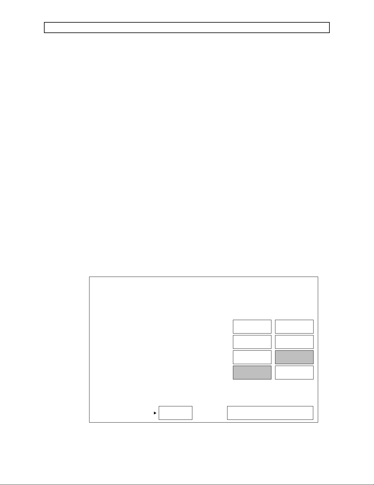
2.2 PMS Schedule
To enter the PMS Screen from the Main Service Screen:
- Use the rotary dial to position the cursor at PMS SCHEDULE, and
press the dial. The cursor will then move to the Month function as
shown in Figure 2-3.
- Press the dial to highlight the function.
- Rotate the dial to select the desired month for the next PMS reminder,
and press the dial to save the setting.
The recommended PMS interval for the Vitalert 3000 Series monitors is three
months. If the current date exceeds that which has been selected and entered,
a Preventive Maintenance Due message will appear on the power-up
diagnostics screen.
Following the PMS month selection:
- Use the rotary dial to set the cursor on MONITORS to proceed with
other maintenance screens . (Selecting MAIN will return you to the
Main Service Screen.)
- Press the dial to enter the selected screen.
SELECT MONTH OF NEXT SCHEDULED PMS
MAR
1993
MAIN
PMS
SCHEDULE
MONITORS
KEYS
Rev. H
ROTATE DIAL TO MOVE CURSOR
PRESS TO ACTIVATE FEATURE
SV30041
Figure 2-3: PMS SCHEDULE SCREEN
2-3
Page 10
RETURN TO THIS MANUAL’S TABLE OF CONTENTS
RETURN TO CD-ROM TABLE OF CONTENTS
DIAGNOSTICS (continued) VA3000
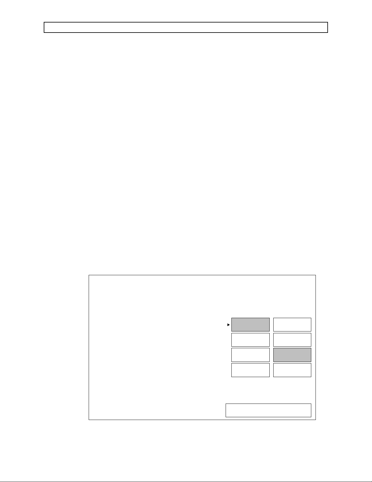
2.3 Monitors
When the cursor is set to MONITORS and the dial is pressed, a second column
of selections is displayed. These are used to select specific monitors as
described in the following paragraphs.
2.3.1 SpO2Service Screen
While still in the Main Service Screen, note the "OXIM SW VERSION"
number. It should be of the form "V x.x.x" or "Vx.x.x.x". The former
indicates that a Nellcor MP-202 is installed. The latter indicates a MP-
203.
Set the cursor to SPO2 and press the dial. A typical SpO
service screen
2
is shown in Figure 2-4.
This screen displays the current values for SpO
and Pulse to verify
2
that the pulse oximeter is operational. A calibration check can be made
by disconnecting the SpO
sensor prior to power up, and connecting a
2
Nellcor® model PT-2500 Pocket Tester. The screen should then display
an SpO
value of 81 ± 1, and a Pulse value of 61 ± 1 for a MP-202, 40
2
± 1 for a MP-203. Connection details are illustrated in Section 5.
To enter another service screen, set the cursor to the desired selection,
and press the dial. (Selecting MAIN and pressing the dial will return
you to the Main Service Screen.)
SPO2 VALUE: 81
PULSE VALUE: 61
SPO2
MAIN
SV30042
Figure 2-4: SpO2SERVICE SCREEN
2-4
NIBP
SAMPLE
LINE
GAS
ANALYZER
ROTATE DIAL TO MOVE CURSOR
PRESS TO ACTIVATE FEATURE
PMS
SCHEDULE
MONITORS
KEYS
Rev. A
Page 11
RETURN TO THIS MANUAL’S TABLE OF CONTENTS
RETURN TO CD-ROM TABLE OF CONTENTS
VA3000 DIAGNOSTICS (continued)
2.3.2 NIBP Service Screen
Set the cursor to NIBP and press the dial. A typical NIBP service
screen is shown in Figure 2-5.
This screen indicates the cuff inflation pressure and also provides a
timing period after inflation for leak testing. On-screen instructions
provide a method of checking pressure calibration with an external
gauge. Connection details are illustrated in Section 5.
- Connect a BP cuff to the patient interface panel on the left side of the
instrument, and wrap the cuff around a cylindrical object.
- Use the rotary dial to position the cursor at TEST, and press the dial
to begin cuff inflation.
- Wait one minute, then compare the test gauge reading with the
displayed CUFF PRESSURE VALUE. The readings should agree
within±5mmHg.
The Cuff Pressure Value will be displayed until the cuff deflates
(approximately four minutes after the start of inflation). The STATUS
line will then display the result of the test.
NOTE: With software version 1.05 the sensitivity of the automatic test
may be too high. If a "FAIL" message appears, perform the leak test
described in Section 5 before making repairs.
To enter another service screen, set the cursor to the desired selection,
and press the dial. (Selecting MAIN and pressing the dial will return
you to the Main Service Screen.)
CUFF PRESSURE VALUE: 300
NIBP CUFF PRESSURE CHECK PROCEDURE:
-PLACE T FITTING INLINE WITH THE BP CUFF
-CONNECT A CALIBRATED PRESSURE GAUGE TO T
-SELECT 'TEST' KEY AND PRESS THE ROTARY
DIAL TO INFLATE CUFF
-VERIFY THAT THE CUFF INFLATES TO 300 MM HG
-WAIT FOR STATUS MESSAGE TO APPEAR BELOW
STATUS: PASS
SPO2
NIBP
SAMPLE
LINE
GAS
ANALYZER
MAIN
PMS
SCHEDULE
MONITORS
KEYS
Rev. A
TEST
SV30043
Figure 2-5: NIBP SERVICE SCREEN
2-5
ROTATE DIAL TO MOVE CURSOR
PRESS TO ACTIVATE FEATURE
Page 12
RETURN TO THIS MANUAL’S TABLE OF CONTENTS
RETURN TO CD-ROM TABLE OF CONTENTS
DIAGNOSTICS (continued) VA3000
2.3.3 Sample Line Flow Service Screen
Set the cursor to SAMPLE LINE and press the dial. A typical Sample
Line service screen is shown in Figure 2-6.
This screen allows gas sample flow rates (100 ml/min. and 200 ml/min.)
to be set using an external flow meter connected to the exhaust port on
the rear panel of the instrument.
A calibration procedure for the Low Flow and High Flow is displayed
on-screen. A more complete calibration procedure for the low and high
flow rates is given in Section 5 along with a calibration verification and
line block alarm test.
To enter another service screen, set the cursor to the desired selection,
and press the dial. (Selecting MAIN and pressing the dial will return
you to the Main Service Screen.)
ALLOW UNIT TO WARM UP FOR 10 MINUTES
LOW FLOW CALIBRATION PROCEDURE
-PLACE A FLOW METER AT THE EXHAUST PORT
-SELECT 'ADJUST FLOW' KEY AND PRESS DIAL
-ADJUST FLOW WITH DIAL UNTIL FLOW METER
INDICATES DESIRED FLOW THEN PRESS DIAL
-BLOCK SAMPLE LINE THEN SELECT 'STORE LOW'
KEY. PRESS THE ROTARY DIAL TO CALIBRATE
HIGH FLOW CALIBRATION PROCEDURE
-PLACE A FLOWMETER AT THE EXHAUST PORT
-SELECT 'ADJUST FLOW' KEY AND PRESS DIAL
-ADJUST FLOW WITH DIAL UNTIL FLOW METER
INDICATES DESIRED FLOW THEN PRESS DIAL
-BLOCK SAMPLE LINE THEN SELECT 'STORE HIGH'
KEY. PRESS THE ROTARY DIAL TO CALIBRATE
ADJUST
FLOW
SV30044
STORE
LOW
STORE
HIGH
SPO2
NIBP
SAMPLE
LINE
GAS
ANALYZER
ROTATE DIAL TO MOVE CURSOR
PRESS TO ACTIVATE FEATURE
Figure 2-6: SAMPLE LINE FLOW SERVICE SCREEN
2-6
MAIN
PMS
SCHEDULE
MONITORS
KEYS
Page 13
MAIN
PMS
SCHEDULE
MONITORS
KEYS
ROTATE DIAL TO MOVE CURSOR
PRESS TO START CALIBRATION
SV30102
SPAN
SPO2
NIBP
SAMPLE
LINE
GAS
ANALYZER
-IN MONITOR SETUP SET FLOW TO MAXIMUM
-MEASURE THE FLOW RATE AT EXHAUST
-WAIT FOR MODE = 'READY'
-ATTACH GAS SAMPLE LINE TO CAL GAS BOTTLE
-SET FLOW ON BOTTLE EQUAL TO EXHAUST FLOW
-SELECT THE 'SPAN' KEY AND PRESS THE
ROTARY DIAL
-MESSAGES APPEAR AS PROCEDURE IS
PERFORMED BY THE MONITOR
CURRENT CO2: 0.0
CURRENT N2O: 0
CURRENT AGENT:
SPAN CALIBRATION PROCEDURE
MODE: READY
STATUS: IDLE
RETURN TO THIS MANUAL’S TABLE OF CONTENTS
RETURN TO CD-ROM TABLE OF CONTENTS
VA3000 DIAGNOSTICS (continued)
2.3.4 Gas Analyzer Service Screen
Set the cursor to GAS ANALYZER and press the dial. A typical Gas
Analyzer service screen is shown in Figure 2-7.
This screen displays current values for CO
O and anesthetic agent,
2,N2
along with a procedure for performing a span calibration of the gas
analyzer using a certified gas sample of known accuracy.
Before performing a span calibration, an accuracy test should be
performed to determine whether a span calibration is needed.
Refer to Section 5 for the complete calibration procedure, including an
accuracy test, equipment required and test connections.
To enter another service screen, set the cursor to the desired selection,
and press the dial. (Selecting MAIN and pressing the dial will return
you to the Main Service Screen.)
Figure 2-7: GAS ANALYZER SERVICE SCREEN
Rev. A
2-7
Page 14

RETURN TO THIS MANUAL’S TABLE OF CONTENTS
RETURN TO CD-ROM TABLE OF CONTENTS
DIAGNOSTICS (continued) VA3000
2.4 Keys
At the time of this writing, the software has not yet been implemented for
producing the test pattern to verify operation of the front panel keys.
Figure 2-8: KEY TEST SCREEN
2-8
Page 15
MAIN
PMS
SCHEDULE
MONITORS
KEYS
SERVICE
RESET
HOURS
ROTATE DIAL TO MOVE CURSOR
PRESS TO ACTIVATE FEATURE
SV30103
MACHINE SERIAL NUMBER
LAST SERVICE DATE
HOURS RUN SINCE LAST SERVICE
TOTAL HOURS RUN
VA3:00004
07-14-93
97
3383
OXIM SW VERSION:
GAI SW VERSION:
GAS BENCH SW VERSION:
V 1.0.7
V 1.2.3
V 1.0.1
SERVICE PERSON
IDENTIFICATION
SERVICE TYPE
2
33 3 3
RETURN TO THIS MANUAL’S TABLE OF CONTENTS
RETURN TO CD-ROM TABLE OF CONTENTS
VA3000 DIAGNOSTICS (continued)
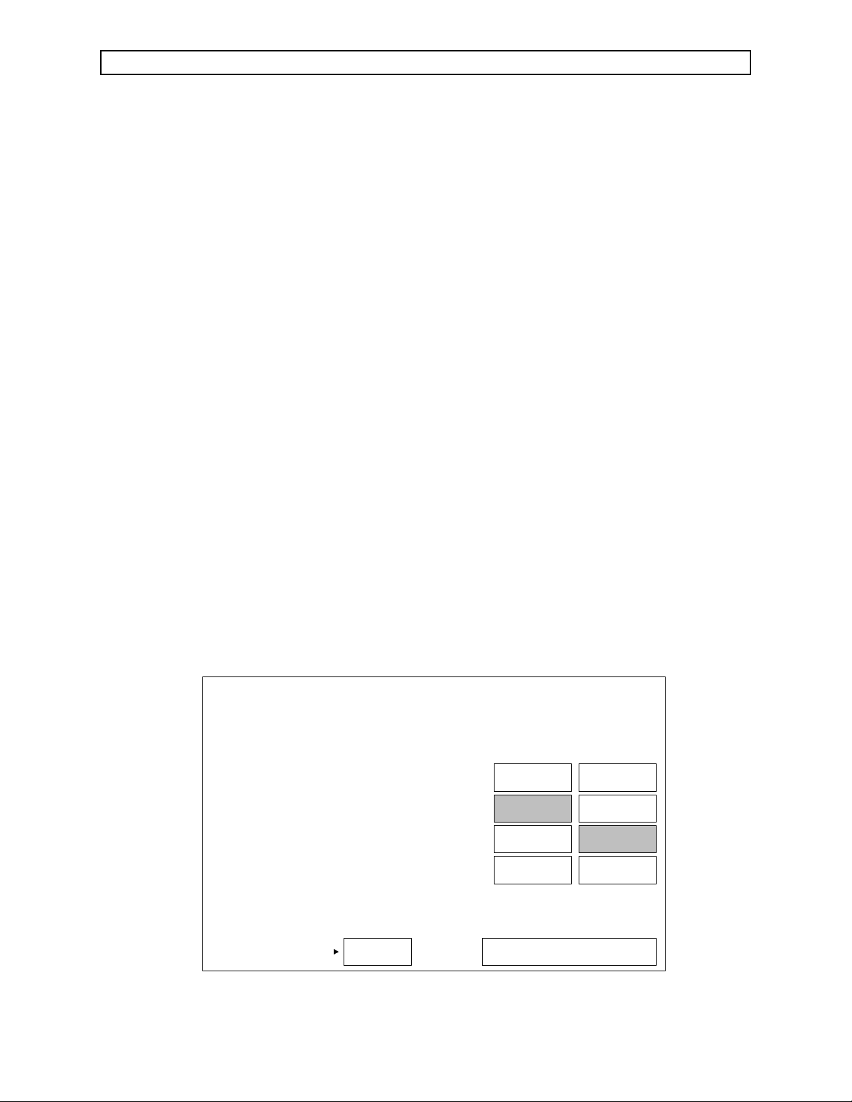
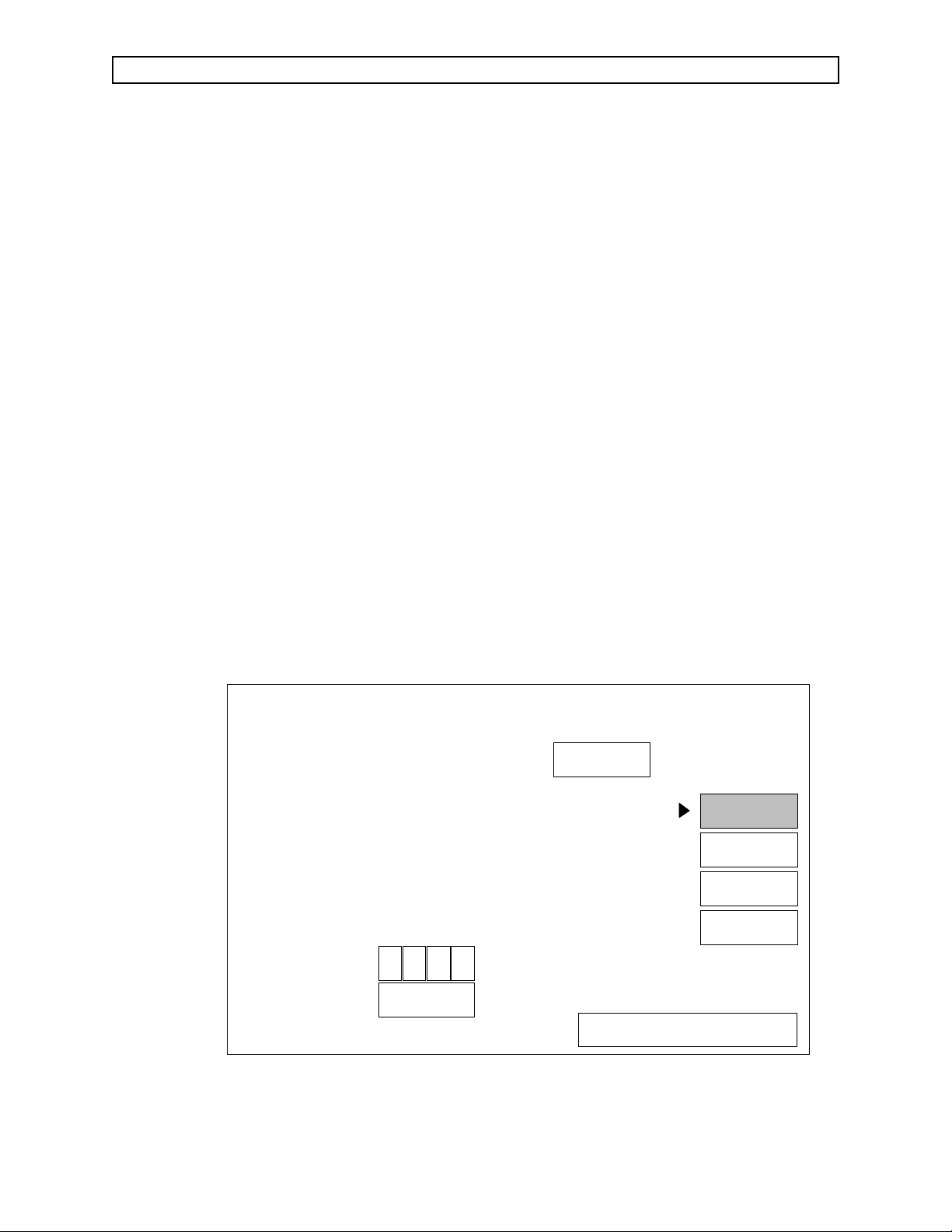
2.5 Secondary Service Screens
The secondary service screens are described on the following pages. These
screens allow viewing and making entries into the service log, and include a
setup screen to turn monitoring functions on or off.
To enter the Secondary Service screens from the Main Service Screen:
- A Service Person Identification must be entered as described under
Paragraph 2.1.
- Using the rotary dial, set the cursor to MAIN, and press the dial to
illuminate the box.
- Slowly turn the dial clockwise until a numeral
2appears at the bottom
of the screen as shown in Figure 2-9.
- Slowly turn the dial counter-clockwise until the numeral
- Slowly turn the dial clockwise until the numeral
6 appears.
5 appears.
- Press the dial to bring up the Service Log Screen (described on the next
page).
Figure 2-9: MAIN SERVICE SCREEN -
SECONDARY SERVICE SCREEN ENTRY
2-9
Page 16

MAIN
SERVICE
LOG
CODES
SETUP
SCROLL
ROTATE DIAL TO MOVE CURSOR
PRESS TO ACTIVATE FEATURE
SV30105
DATE TIME PARAMETER CODE EVENT
06-07-93
06-07-93
06-07-93
06-11-93
06-14-93
06-14-93
11:47
11:50
11:50
15:26
06:57
06:57
1234
00000000
00000820
00000021
00000021
1234
S002 PMS
NIBP MONITOR ERROR
"ENTERING FULL ACCURACY"
"GASBENCH STATUS REPORT"
"GASBENCH STATUS REPORT"
S004 SECONDARY SRVC SCREEN ENTRY
RETURN TO THIS MANUAL’S TABLE OF CONTENTS
RETURN TO CD-ROM TABLE OF CONTENTS
DIAGNOSTICS (continued) VA3000
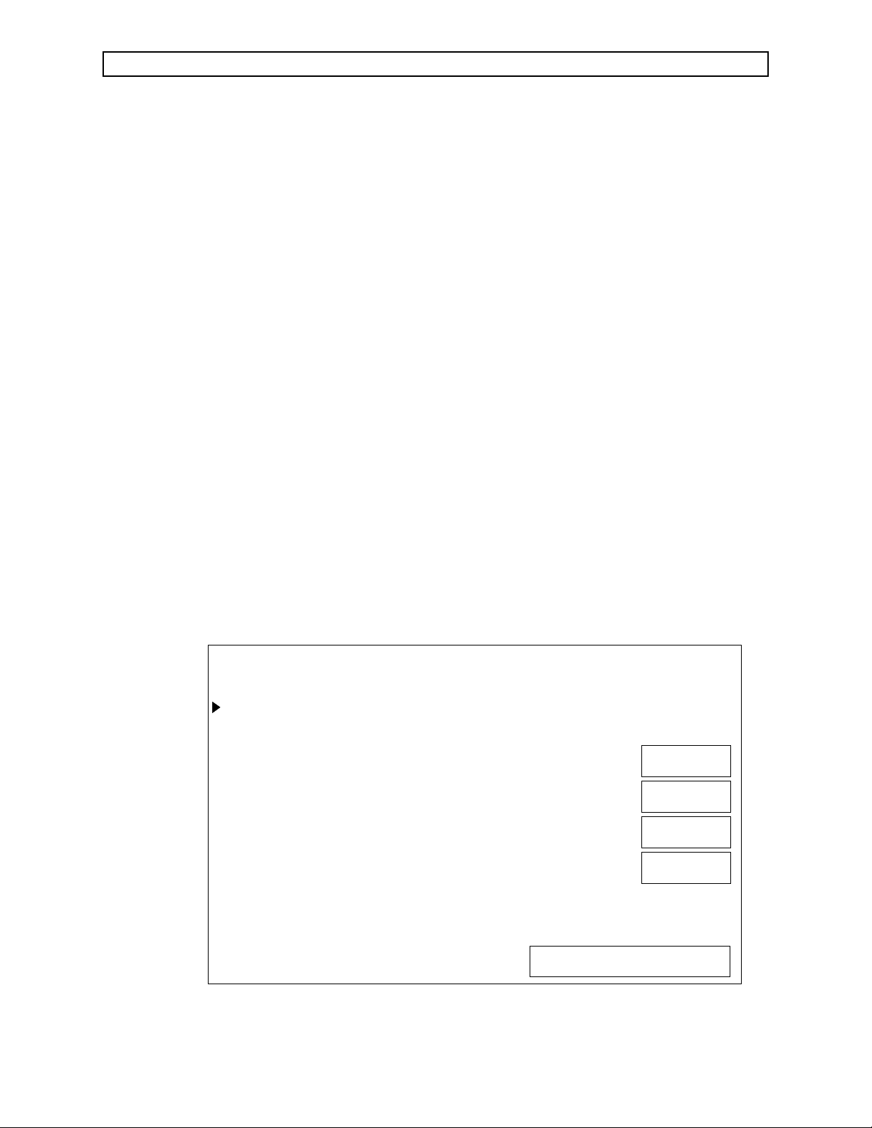
2.5.1 Service Log Screen
Set the cursor to SERVICE LOG and press the dial to enter the Service
Log Screen.
The Service Log Screen presents a chronological listing of operational
and service events as shown in Figure 2-10. When this screen appears,
the most recent entries are displayed.
To scroll through the complete list, set the cursor to SCROLL and press
the dial. Turning the dial clockwise or counter-clockwise will allow you
to scroll backward or forward through the list.
To add a service entry to the log, refer to the Codes screen described on
the next page.
To enter another secondary service screen, set the cursor to the desired
selection, and press the dial. (Selecting MAIN and pressing the dial will
return you to the Main Service Screen.)
Figure 2-10: SERVICE LOG SCREEN
2-10
Page 17
MAIN
SERVICE
LOG
CODES
SETUP
ENTER INTO LOG? YES NO
ROTATE DIAL TO MOVE CURSOR
PRESS TO ACTIVATE FEATURE
SV30106
EVENTCODE
R001
R002
R003
R004
R005
R006
R007
R008
R009
R010
R011
R012
R013
R014
R015
R016
PRESSED MASTER RESET
REPLACE CORD SET
REPLACE BREAKER
REPLACE POWER SUPPLY
REPAIR POWER SUPPLY
REPLACE MAIN CPU
REPAIR MAIN CPU
UPDATE MAIN SW
REPLACE BEZEL ASM
REPLACE KEYBOARD
REPAIR KEYBOARD
REPLACE DISPLAY PANEL
REPLACE SPO2/ISO ASM
REPLACE SPO2 PCB
REPLACE ISO PCB
REPLACE GAS SUB ASM
EVENTCODE
R017
R018
R019
R020
R021
R022
R023
R024
R025
R026
R027
REPLACE ANALYZER
REPAIR ANALYZER
REPLACE GAI PCB
REPAIR GAI PCB
REPLACE FAN
REPLACE SOLENOID
REPLACE HOSE(S)
REPLACE NIBP ASM
REPLACE CABLE(S)
REPLACE COVER
REPLACE BEZEL
RETURN TO THIS MANUAL’S TABLE OF CONTENTS
RETURN TO CD-ROM TABLE OF CONTENTS
VA3000 DIAGNOSTICS (continued)
2.5.2 Codes Screen
Set the cursor to CODES and press the dial to enter the Codes screen.
The Codes Screen presents a list of service codes and related events
that can be selected and entered into the service log. See Figure 2-11.
To place an entry into the service log:
- Turn the dial to scroll through the list, and set the cursor in
front of the selected entry.
- Press the dial.
- Position the cursor at YES or NO, as desired, and press the dial.
If YES is chosen, the selected entry will be placed in the service
log. If NO is chosen, the selected entry will be cancelled and
another selection can be made.
To enter another secondary service screen, set the cursor to the desired
selection, and press the dial. (Selecting MAIN and pressing the dial will
return you to the Main Service Screen.)
Figure 2-11: CODES SCREEN
2-11
Page 18
MAIN
SERVICE
LOG
CODES
KEYS
FACTORY
RESET
ROTATE DIAL TO MOVE CURSOR
PRESS TO ACTIVATE FEATURE
SV30107
MACHINE SERIAL NUMBER: VA3
WARNING:
THE FACTORY RESET IS TO BE DONE
ONLY BY NORTH AMERICAN DRAGER.
ALL SETTINGS AND CALIBRATIONS MUST
BE REDONE FOLLOWING A FACTORY RESET.
IMPORTANT SERVICE DATA WILL BE LOST.
MONITORING FUNCTIONS
NIBP
SPO2
SEVO
DES
ON
ON
ON
ON
914 0
0
RETURN TO THIS MANUAL’S TABLE OF CONTENTS
RETURN TO CD-ROM TABLE OF CONTENTS
DIAGNOSTICS (continued) VA3000
2.5.3 Setup Screen
Set the cursor to SETUP and press the dial to enter the Setup screen.
The Setup screen, shown in Figure 2-12, provides the following
functions:
- Allows entry of the machine serial number (for display on the
Main Service Screen). This needs to be done when a processor
board is replaced, and may also need to be done when software
is updated.
- Allows monitoring functions to be turned OFF or ON.
- Allows Factory Reset to delete the calibration settings and clear
the service log.
WARNING: The factory reset is to be done only by Drägerservice. All
settings and calibrations must be redone following a
factory reset. Important service data will be lost.
To enter another secondary service screen, set the cursor to the desired
selection, and press the dial. (Selecting MAIN and pressing the dial will
return you to the Main Service Screen.)
Figure 2-12: SETUP SCREEN
2-12
Page 19

RETURN TO THIS MANUAL’S TABLE OF CONTENTS
RETURN TO CD-ROM TABLE OF CONTENTS
VA3000 TROUBLESHOOTING GUIDE
3.0 TROUBLESHOOTING
This section contains information to assist the Technical Service Representative (TSR)
in locating electrical faults affecting the VITALERT 3000 Series monitors. Since most
troubleshooting efforts begin with verifying power supply voltages, the following
paragraph outlines the voltage distribution scheme within the instrument along with
cable connector identification.
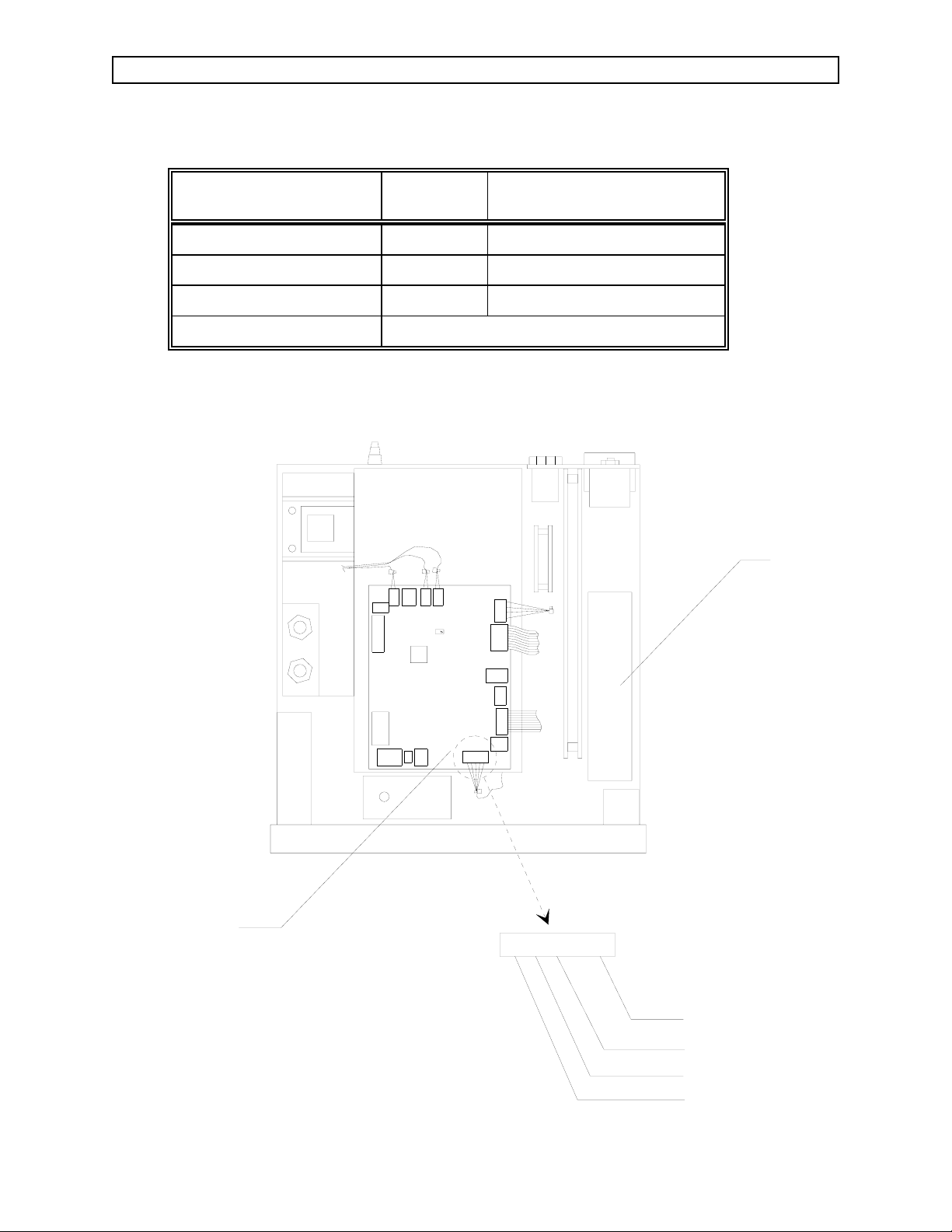
3.1 Power Supply and Voltage Distribution
Figure 3-1 shows a block diagram of the voltage distribution within the
VITALERT 3000 from the power supply. J7 on the Gas Analyzer Interface PCB
(see Figure 3-2) provides the safest, most convenient point to measure power
supply voltages. The voltages are given in Table 3-1 along with their allowable
tolerances. Refer to Section 4 of this manual for appropriate removal and
replacement procedures.
J7
J12
J3
MAINS
SPO2
ASM
NIBP
DISPLAY
FILTER
GAS
ANALYZER
J1
J5
J4
J14
CB1
J1
PROCESSOR
POWER
SUPPLY
Figure 3-1: VITALERT 3000 VOLTAGE DISTRIBUTION
Rev. G
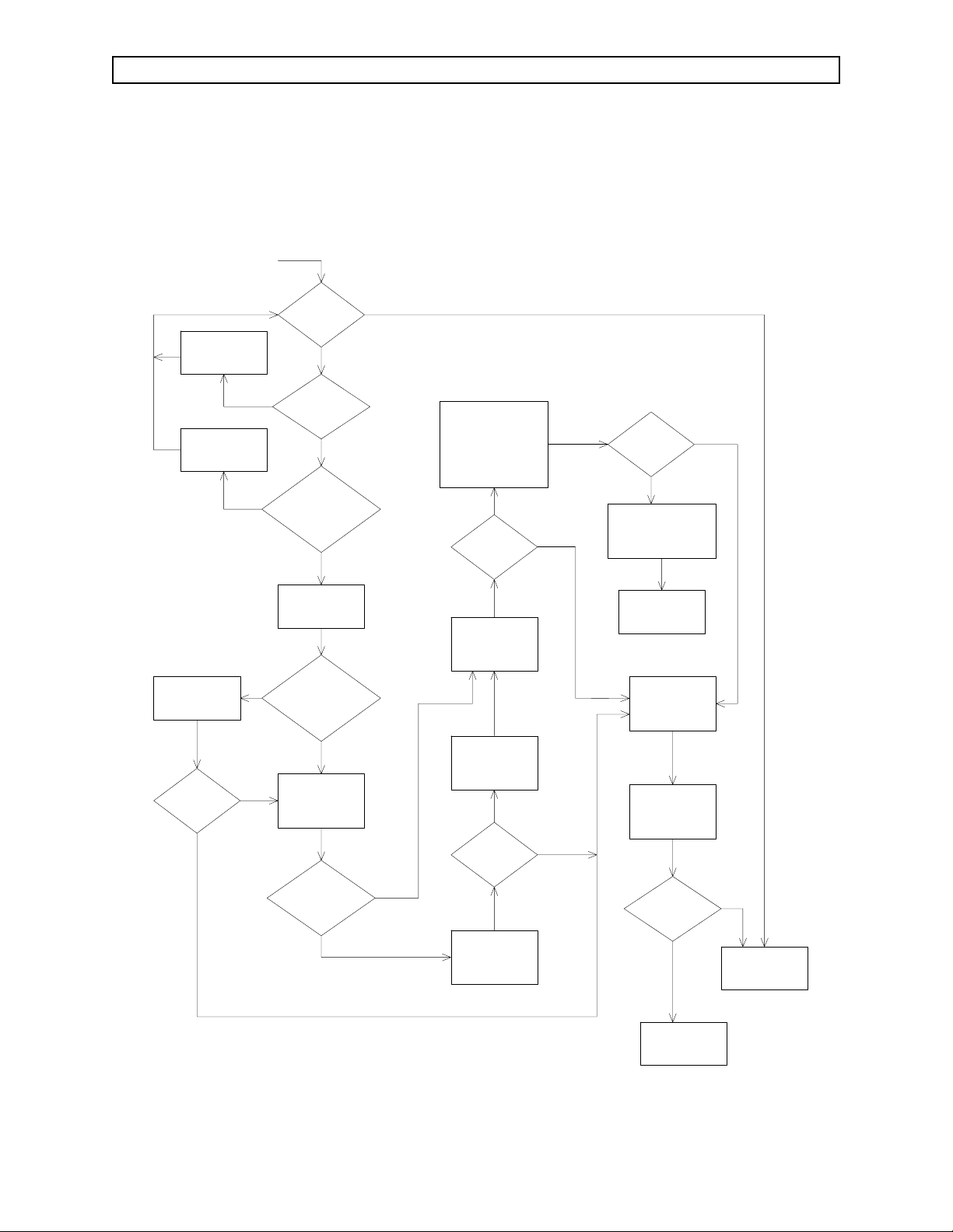
3.2 Troubleshooting Guides
Table 3-2 lists common failure modes and symptoms (excluding simultaneous
multiple faults) for the Vitalert 3000 Series monitors. Each failure mode or
symptom is keyed to a troubleshooting guide flow chart on the following pages
to assist the TSR in locating a problem.These flow charts assume that the
instrument is plugged into an AC outlet with the correct voltage. If a problem
occurs that cannot be corrected by following these guides, call DrägerService
for support.
3-1
Page 20
RETURN TO THIS MANUAL’S TABLE OF CONTENTS
RETURN TO CD-ROM TABLE OF CONTENTS
TROUBLESHOOTING GUIDE (continued) VA3000
TABLE 3-1: POWER SUPPLY VOLTAGES AND TOLERANCES
GAS IF PCB, PWR SUPP
VOLTAGE ACCEPTABLE RANGE
WIRE HARNESS
J7-5 (Pur) + 5 VDC 4.85 to 5.15 VDC
J7-3 (Yel) +12VDC 11.76 to 12.24 VDC
J7-1 (Yel/Wht) -12VDC -11.76 to -12.24 VDC
J7-4 (Blk) Common
TOP VIEW OF VITALERT 3000
WITH COVER REMOVED
J4
J8
J14
J1
J6
J2
U3
J3
J12
J5
J11
J16
J18
J15
J10
J13
J7
J9
POWER
SUPPLY
GAS ANALYZER
INTERFACE BOARD
TEST POINTS
FOR POWER
SUPPLY VOLTAGE
SV30130
Figure 3-2: POWER SUPPLY TEST POINTS
3-2
54321
(YEL/ WH) - 12 VDC
(YEL) + 12 VDC
(BLK) COMMON
(PUR) + 5 VDC
Rev. G
Page 21

RETURN TO THIS MANUAL’S TABLE OF CONTENTS
RETURN TO CD-ROM TABLE OF CONTENTS
VA3000 TROUBLESHOOTING GUIDE (continued)
TABLE 3-2: VITALERT 3000 TROUBLESHOOTING GUIDES
FAILURE MODE / SYMPTOM CORRECTIVE ACTION
Display blank upon system power-up Guide 1
Firmware Test fails upon system power-up Guide 2
Video Test fails upon system power-up Guide 3
Memory Test fails upon system power-up Guide 4
Timer Test fails upon system power up Guide 5
Audio Test - Primary fails upon system power-up Guide 6
Audio Test - Backup fails upon system power-up Guide 7
Audio Test - SpO2fails upon power-up Guide 8
Serial I/O Test fails upon system power-up Guide 9
Clock Test fails upon system power-up Guide 10
NVRAM Test fails upon system power-up Guide 11
"SERVICE GAS MON" Advisory error Guide 12
"SERVICE NIBP MON" Advisory error Guide 13
"SERVICE SPO2 MON" Advisory error Guide 14
Vitalink failure Guide 15
Low or No Flow at CO2exhaust port Guide 16
Line Block message displayed Guide 17
Instrument will not power-up Guide 18
Front Keys and/or Rotary Dial not functional Guide 19
NIBP readings inacurate Guide 20
Instrument is performing intermittent resets Guide 21
Analyzer fails Span Cal Guide 22
3-3
Page 22
RETURN TO THIS MANUAL’S TABLE OF CONTENTS
RETURN TO CD-ROM TABLE OF CONTENTS
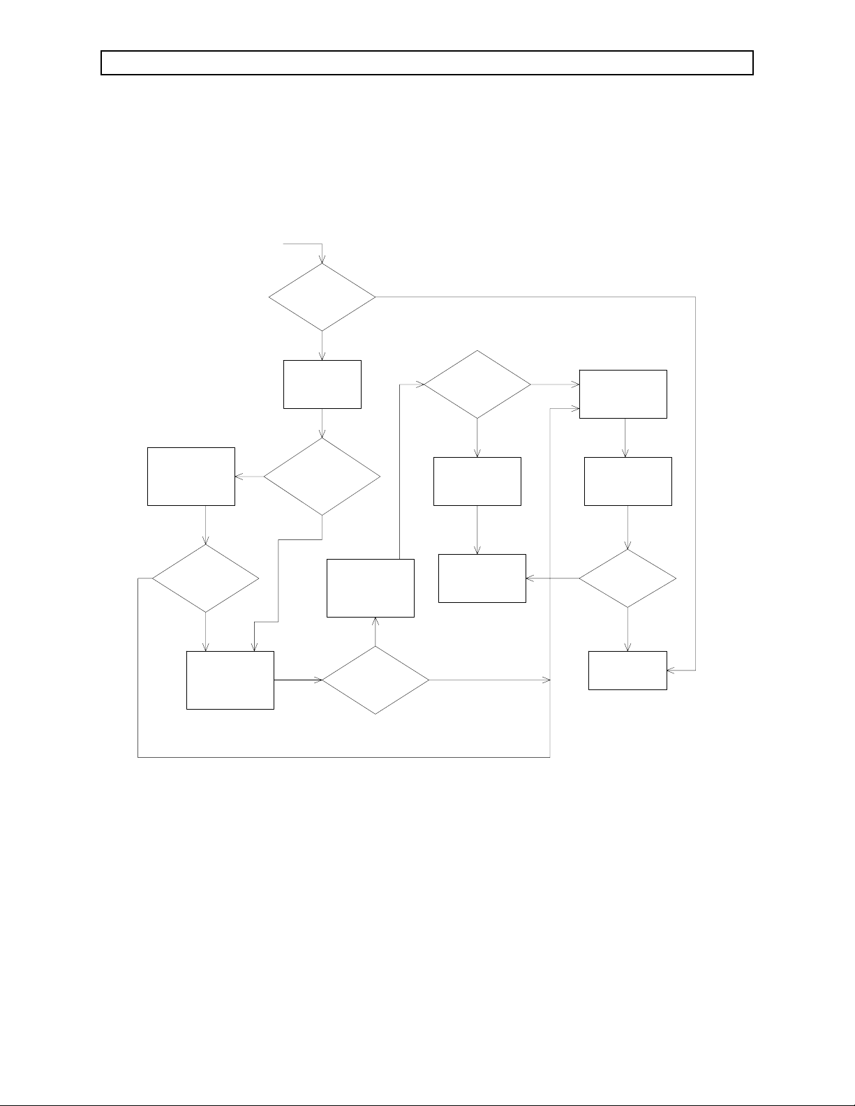
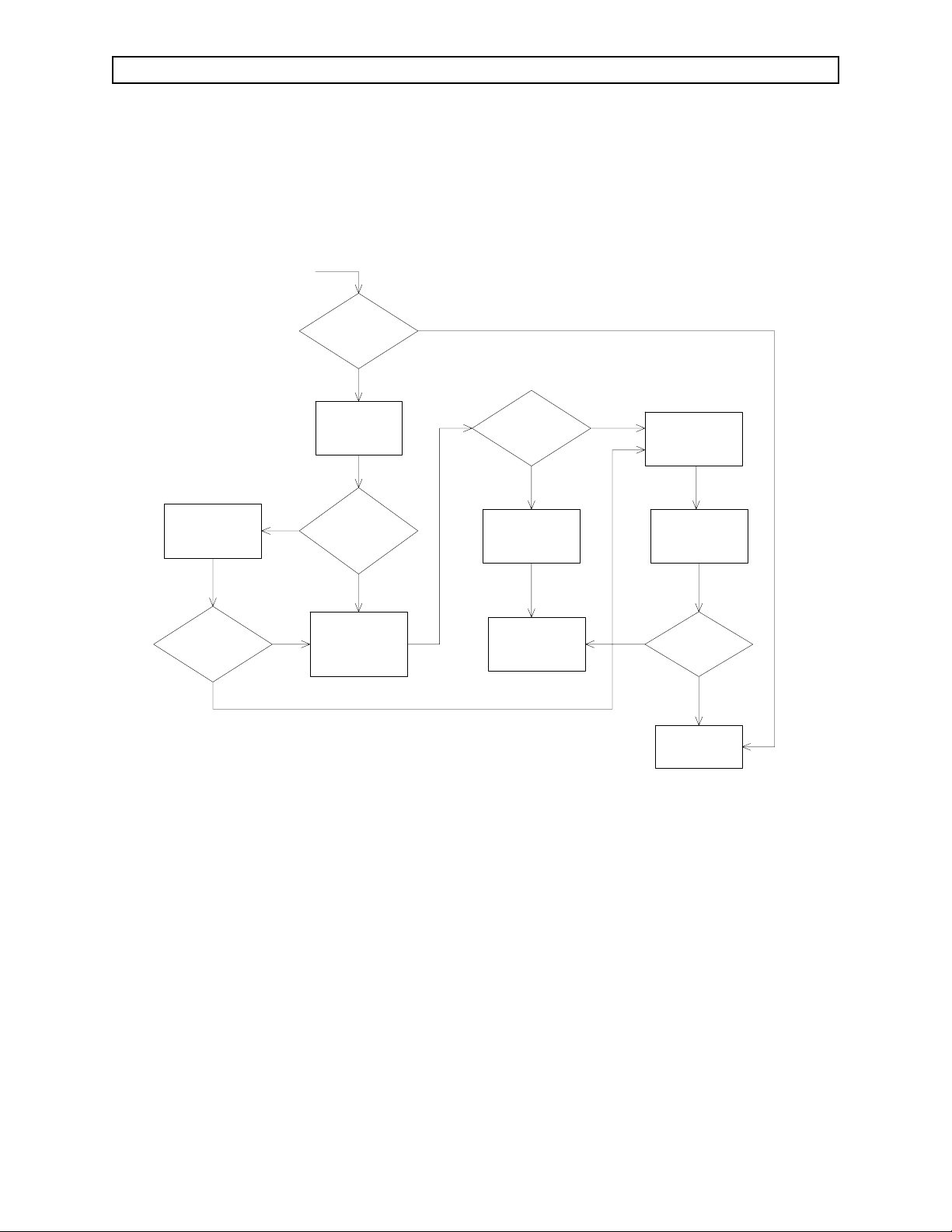
TROUBLESHOOTING GUIDE (continued) VA3000
GUIDE 1: Display blank upon system power-up
START
ENABLE
CIRCUIT
BREAKER
PLUG VA3000
INTO A LIVE
AC RECEPTACLE
CONNECT
CABLES
SECURELY
IS
DISPLAY
BLANK?
DISPLAY
N
CIRCUIT BREAKER
ENABLED?
N
PLUGGED INTO LIVE
AC RECEPTACLE?
REMOVE COVER
AS OUTLINED IN
PROCEDURE 4.1
N
ALL INTERNAL CABLES
CONNECTED?
Y
CHECK POWER
SUPPLY VOLTAGES
AS OUTLINED IN
SECTION 3.1
IS
BLANK?
Y
IS
Y
IS
VA3000
Y
ARE
Y
N
REINSTALL ORIGINAL
MONITOR BEZEL
------------------------------REPLACE
PROCESSOR ASSEMBLY
AS OUTLINED IN
PROCEDURE 4.2
Y
IS
DISPLAY
BLANK?
REPLACE
MONITOR BEZEL
AS OUTLINED IN
PROCEDURE 4.4
REINSTALL ORIGINAL
POWER SUPPLY
ASSEMBLY
N
Y
IS
DISPLAY
BLANK?
REINSTALL ORIGINAL
PROCESSOR ASSEMBLY
AND COVER
CONTACT NAD
SERVICE DEPT.
REINSTALL COVER
AS OUTLINED IN
PROCEDURE 4.1
PERFORM A
COMPLETE PMS
N
Y
N
ARE
VOLTAGES WITHIN
SPEC?
N
Y
IS
DISPLAY
BLANK?
REPLACE POWER
SUPPLY ASSEMBLY
AS OUTLINED IN
PROCEDURE 4.3
N
DOES
UNIT PASS
PMS?
CONTACT NAD
SERVICE DEPT.
Y
N
UNIT IS
FUNCTIONAL
3-4
Page 23
RETURN TO THIS MANUAL’S TABLE OF CONTENTS
RETURN TO CD-ROM TABLE OF CONTENTS
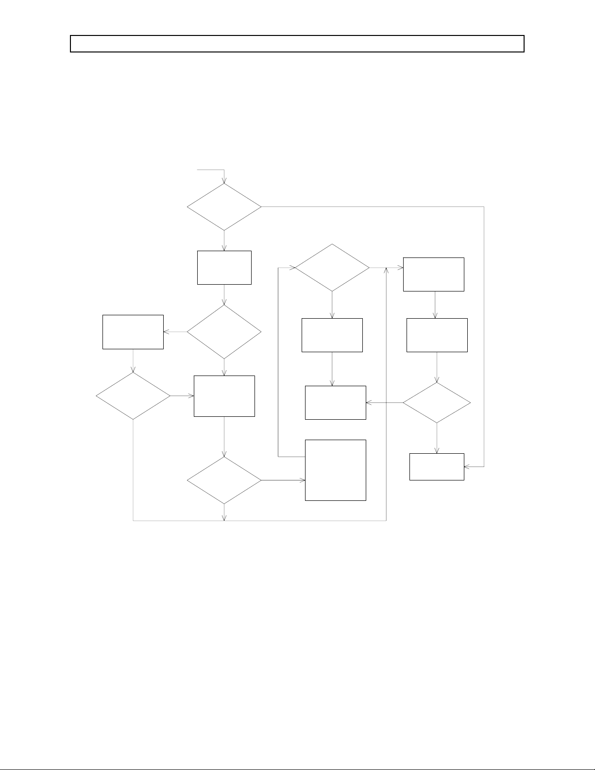
VA3000 TROUBLESHOOTING GUIDE (continued)
GUIDE 2: Firmware Test fails upon system power-up
START
CONNECT ALL
PROCESSOR BOARD
AND INTERNAL CABLES
DOES
FIRMWARE TEST
FAIL UPON SYSTEM
POWER-UP?
N
N
Y
DOES
FIRMWARE TEST
FAIL UPON SYSTEM
POWER-UP?
Y
REMOVE COVER
AS OUTLINED IN
PROCEDURE 4.1
ARE
ALL CABLES
CONNECTED TO
PROCESSOR
BOARD?
Y
REPLACE
FIRMWARE
AS OUTLINED IN
PROCEDURE 4.9
DOES
FIRMWARE TEST
FAIL UPON SYSTEM
POWER-UP?
N
DOES
FIRMWARE TEST
FAIL UPON SYSTEM
POWER-UP?
Y
REINSTALL ORIGINAL
PROCESSOR BOARD
AND COVER
CONTACT NAD
SERVICE DEPT.
REINSTALL ORIGINAL
FIRMWARE
----------------------------------
Y
REPLACE
PROCESSOR BOARD
AS OUTLINED IN
PROCEDURE 4.2
N
REINSTALL COVER
AS OUTLINED IN
PROCEDURE 4.1
PERFORM A
COMPLETE PMS
ON UNIT
N
DOES
UNIT PASS
PMS?
UNIT IS
FUNCTIONAL
Y
N
3-5
Page 24

RETURN TO THIS MANUAL’S TABLE OF CONTENTS
RETURN TO CD-ROM TABLE OF CONTENTS
TROUBLESHOOTING GUIDE (continued) VA3000
GUIDE 3: Video Test fails upon system power-up
START
CONNECT ALL
PROCESSOR BOARD
AND INTERNAL CABLES
DOES
VIDEO TEST
FAIL UPON SYSTEM
POWER-UP?
N
N
Y
DOES
VIDEO TEST
FAIL UPON SYSTEM
POWER-UP?
Y
REMOVE COVER
AS OUTLINED IN
PROCEDURE 4.1
ARE
ALL CABLES
CONNECTED TO
PROCESSOR
BOARD?
Y
REPLACE
PROCESSOR BOARD
AS OUTLINED IN
PROCEDURE 4.2
N
DOES
VIDEO TEST
FAIL UPON SYSTEM
POWER-UP?
Y
REINSTALL ORIGINAL
PROCESSOR BOARD
AND COVER
CONTACT NAD
SERVICE DEPT.
N
REINSTALL COVER
AS OUTLINED IN
PROCEDURE 4.1
PERFORM A
COMPLETE PMS
ON UNIT
N
DOES
UNIT PASS
PMS?
UNIT IS
FUNCTIONAL
Y
3-6
Page 25

RETURN TO THIS MANUAL’S TABLE OF CONTENTS
RETURN TO CD-ROM TABLE OF CONTENTS
VA3000 TROUBLESHOOTING GUIDE (continued)
GUIDE 4: Memory Test fails upon system power-up
START
CONNECT ALL
PROCESSOR BOARD
AND INTERNAL CABLES
DOES
MEMORY TEST
FAIL UPON SYSTEM
POWER-UP?
N
N
Y
DOES
MEMORY TEST
FAIL UPON SYSTEM
POWER-UP?
Y
REMOVE COVER
AS OUTLINED IN
PROCEDURE 4.1
ARE
ALL CABLES
CONNECTED TO
PROCESSOR
BOARD?
Y
REPLACE
PROCESSOR BOARD
AS OUTLINED IN
PROCEDURE 4.2
N
DOES
MEMORY TEST
FAIL UPON SYSTEM
POWER-UP?
Y
REINSTALL ORIGINAL
PROCESSOR BOARD
AND COVER
CONTACT NAD
SERVICE DEPT.
N
REINSTALL COVER
AS OUTLINED IN
PROCEDURE 4.1
PERFORM A
COMPLETE PMS
ON UNIT
N
DOES
UNIT PASS
PMS?
UNIT IS
FUNCTIONAL
Y
3-7
Page 26

RETURN TO THIS MANUAL’S TABLE OF CONTENTS
RETURN TO CD-ROM TABLE OF CONTENTS
TROUBLESHOOTING GUIDE (continued) VA3000
GUIDE 5: Timer Test fails upon system power up
START
CONNECT ALL
PROCESSOR BOARD
AND INTERNAL CABLES
DOES
TIMER TEST
FAIL UPON SYSTEM
POWER-UP?
N
N
Y
DOES
TIMER TEST
FAIL UPON SYSTEM
POWER-UP?
Y
REMOVE COVER
AS OUTLINED IN
PROCEDURE 4.1
ARE
ALL CABLES
CONNECTED TO
PROCESSOR
BOARD?
Y
REPLACE
PROCESSOR BOARD
AS OUTLINED IN
PROCEDURE 4.2
N
DOES
TIMER TEST
FAIL UPON SYSTEM
POWER-UP?
Y
REINSTALL ORIGINAL
PROCESSOR BOARD
AND COVER
CONTACT NAD
SERVICE DEPT.
N
REINSTALL COVER
AS OUTLINED IN
PROCEDURE 4.1
PERFORM A
COMPLETE PMS
ON UNIT
N
DOES
UNIT PASS
PMS?
UNIT IS
FUNCTIONAL
Y
3-8
Page 27

RETURN TO THIS MANUAL’S TABLE OF CONTENTS
RETURN TO CD-ROM TABLE OF CONTENTS
VA3000 TROUBLESHOOTING GUIDE (continued)
GUIDE 6: Audio Test - Primary fails upon system power-up
START
CONNECT PRIMARY
SPEAKER CABLE TO
J15 ON PROCESSOR
BOARD
N
DOES
AUDIO TEST-PRIMARY
FAIL UPON SYSTEM
POWER-UP?
Y
REPLACE PRIMARY
SPEAKER (TOP)
AS OUTLINED IN
PROCEDURE 4.2
DOES
AUDIO TEST-PRIMARY
FAIL UPON SYSTEM
POWER-UP?
REMOVE COVER
AS OUTLINED IN
PROCEDURE 4.1
N
IS
PRIMARY SPEAKER
CABLE CONNECTED TO
J15 ON PROCESSOR
BOARD?
N
Y
Y
REPLACE
PROCESSOR BOARD
AS OUTLINED IN
PROCEDURE 4.2
Y
DOES
AUDIO TEST-PRIMARY
FAIL UPON SYSTEM
POWER-UP?
DOES
AUDIO TEST-PRIMARY
FAIL UPON SYSTEM
POWER-UP?
Y
REINSTALL ORIGINAL
PROCESSOR BOARD
AND COVER
CONTACT NAD
SERVICE DEPT.
N
N
REINSTALL COVER
AS OUTLINED IN
PROCEDURE 4.1
PERFORM A
COMPLETE PMS
ON UNIT
N
DOES
UNIT PASS
PMS?
UNIT IS
FUNCTIONAL
Y
3-9
Page 28

RETURN TO THIS MANUAL’S TABLE OF CONTENTS
RETURN TO CD-ROM TABLE OF CONTENTS
TROUBLESHOOTING GUIDE (continued) VA3000
GUIDE 7: Audio Test - Backup fails upon system power-up
START
CONNECT ALL
PROCESSOR BOARD
AND INTERNAL CABLES
DOES
AUDIO BACKUP TEST
FAIL UPON SYSTEM
POWER-UP?
N
AUDIO BACKUP TEST
N
Y
PROCESSOR BOARD
DOES
FAIL UPON SYSTEM
POWER-UP?
Y
REMOVE COVER
AS OUTLINED IN
PROCEDURE 4.1
ARE
ALL CABLES
CONNECTED TO
PROCESSOR
BOARD?
Y
REPLACE
AS OUTLINED IN
PROCEDURE 4.2
N
DOES
AUDIO BACKUP TEST
FAIL UPON SYSTEM
POWER-UP?
Y
REINSTALL ORIGINAL
PROCESSOR BOARD
AND COVER
CONTACT NAD
SERVICE DEPT.
N
REINSTALL COVER
AS OUTLINED IN
PROCEDURE 4.1
PERFORM A
COMPLETE PMS
ON UNIT
N
DOES
UNIT PASS
PMS?
UNIT IS
FUNCTIONAL
Y
3-10
Page 29
RETURN TO THIS MANUAL’S TABLE OF CONTENTS
RETURN TO CD-ROM TABLE OF CONTENTS
VA3000 TROUBLESHOOTING GUIDE (continued)
CONNECT SPO2
SPEAKER CABLE TO
J16 ON PROCESSOR
BOARD
START
DOES
AUDIO TEST-SPO2
FAIL UPON SYSTEM
POWER-UP?
REMOVE COVER
AS OUTLINED IN
PROCEDURE 4.1
N
IS
SPO2 SPEAKER
CABLE CONNECTED TO
J16 ON PROCESSOR
BOARD?
GUIDE 8: Audio Test - SpO
N
Y
DOES
AUDIO TEST-SPO2
FAIL UPON SYSTEM
POWER-UP?
Y
REINSTALL ORIGINAL
PROCESSOR BOARD
AND COVER
Y
N
fails upon power-up
2
REINSTALL COVER
AS OUTLINED IN
PROCEDURE 4.1
PERFORM A
COMPLETE PMS
ON UNIT
N
DOES
AUDIO TEST-SPO2
FAIL UPON SYSTEM
POWER-UP?
REPLACE SPO2
SPEAKER (BOTTOM)
AS OUTLINED IN
PROCEDURE 4.2
REPLACE
PROCESSOR BOARD
AS OUTLINED IN
PROCEDURE 4.2
Y
Y
DOES
AUDIO TEST-SPO2
FAIL UPON SYSTEM
POWER-UP?
CONTACT NAD
SERVICE DEPT.
N
N
DOES
UNIT PASS
PMS?
Y
UNIT IS
FUNCTIONAL
3-11
Page 30
RETURN TO THIS MANUAL’S TABLE OF CONTENTS
RETURN TO CD-ROM TABLE OF CONTENTS
TROUBLESHOOTING GUIDE (continued) VA3000
GUIDE 9: Serial I/O Test fails upon system power-up
START
CONNECT ALL
PROCESSOR BOARD
AND INTERNAL CABLES
DOES
SERIAL I/O TEST
FAIL UPON SYSTEM
POWER-UP?
N
N
Y
DOES
SERIAL I/O TEST
FAIL UPON SYSTEM
POWER-UP?
Y
REMOVE COVER
AS OUTLINED IN
PROCEDURE 4.1
ARE
ALL CABLES
CONNECTED TO
PROCESSOR
BOARD?
Y
REPLACE
PROCESSOR BOARD
AS OUTLINED IN
PROCEDURE 4.2
N
DOES
SERIAL I/O TEST
FAIL UPON SYSTEM
POWER-UP?
Y
REINSTALL ORIGINAL
PROCESSOR BOARD
AND COVER
CONTACT NAD
SERVICE DEPT.
N
REINSTALL COVER
AS OUTLINED IN
PROCEDURE 4.1
PERFORM A
COMPLETE PMS
ON UNIT
N
DOES
UNIT PASS
PMS?
UNIT IS
FUNCTIONAL
Y
3-12
Page 31

RETURN TO THIS MANUAL’S TABLE OF CONTENTS
RETURN TO CD-ROM TABLE OF CONTENTS
VA3000 TROUBLESHOOTING GUIDE (continued)
GUIDE 10: Clock Test fails upon system power-up
START
CONNECT ALL
PROCESSOR BOARD
AND INTERNAL CABLES
DOES
CLOCK TEST
FAIL UPON SYSTEM
POWER-UP?
N
N
Y
DOES
CLOCK TEST
FAIL UPON SYSTEM
POWER-UP?
Y
REMOVE COVER
AS OUTLINED IN
PROCEDURE 4.1
ARE
ALL CABLES
CONNECTED TO
PROCESSOR
BOARD?
Y
REPLACE
PROCESSOR BOARD
AS OUTLINED IN
PROCEDURE 4.2
N
DOES
CLOCK TEST
FAIL UPON SYSTEM
POWER-UP?
Y
REINSTALL ORIGINAL
PROCESSOR BOARD
AND COVER
CONTACT NAD
SERVICE DEPT.
N
REINSTALL COVER
AS OUTLINED IN
PROCEDURE 4.1
PERFORM A
COMPLETE PMS
ON UNIT
N
DOES
UNIT PASS
PMS?
UNIT IS
FUNCTIONAL
Y
3-13
Page 32

RETURN TO THIS MANUAL’S TABLE OF CONTENTS
RETURN TO CD-ROM TABLE OF CONTENTS
TROUBLESHOOTING GUIDE (continued) VA3000
GUIDE 11: NVRAM Test fails upon system power-up
START
CONNECT ALL
PROCESSOR BOARD
AND INTERNAL CABLES
DOES
NVRAM TEST
FAIL UPON SYSTEM
POWER-UP?
N
N
Y
DOES
NVRAM TEST
FAIL UPON SYSTEM
POWER-UP?
Y
REMOVE COVER
AS OUTLINED IN
PROCEDURE 4.1
ARE
ALL CABLES
CONNECTED TO
PROCESSOR
BOARD?
Y
REPLACE
PROCESSOR BOARD
AS OUTLINED IN
PROCEDURE 4.2
N
DOES
NVRAM TEST
FAIL UPON SYSTEM
POWER-UP?
Y
REINSTALL ORIGINAL
PROCESSOR BOARD
AND COVER
CONTACT NAD
SERVICE DEPT.
N
REINSTALL COVER
AS OUTLINED IN
PROCEDURE 4.1
PERFORM A
COMPLETE PMS
ON UNIT
N
DOES
UNIT PASS
PMS?
UNIT IS
FUNCTIONAL
Y
3-14
Page 33

RETURN TO THIS MANUAL’S TABLE OF CONTENTS
RETURN TO CD-ROM TABLE OF CONTENTS
VA3000 TROUBLESHOOTING GUIDE (continued)
GUIDE 12: "SERVICE GAS MON" Advisory error
START
ATTACH ALL
CABLES TO GAS
ANALYZER
DOES
ADVISORY COLUMN
DISPLAY "SERVICE
GAS MON"?
PERFORM SPAN
CALIBRATION
AS OUTLINED IN
PROCEDURE 5.4
DOES
ADVISORY COLUMN
DISPLAY "SERVICE
GAS MON"?
REMOVE COVER
AS OUTLINED IN
PROCEDURE 4.1
N
ARE
ALL CABLES
CONNECTED TO GAS
ANALYZER?
N
Y
N
Y
DOES
ADVISORY COLUMN
DISPLAY "SERVICE
GAS MON"?
Y
REINSTALL ORIGINAL
GAS ANALYZER ASM
---------------------------REPLACE
PROCESSOR ASM
AS OUTLINED IN
PROCEDURE 4.2
PERFORM SPAN
CALIBRATION
AS OUTLINED IN
PROCEDURE 5.4
DOES
ADVISORY COLUMN
DISPLAY "SERVICE
GAS MON"?
N
N
REINSTALL COVER
AS OUTLINED IN
PROCEDURE 4.1
DOES
ADVISORY COLUMN
DISPLAY "SERVICE
GAS MON"?
N
REPLACE GAS
Y
AS OUTLINED IN
PROCEDURE 4.7
N
ADVISORY COLUMN
DISPLAY "SERVICE
PERFORM SPAN
AS OUTLINED IN
PROCEDURE 5.4
Y
ANALYZER
DOES
GAS MON"?
Y
CALIBRATION
REINSTALL ORIGINAL
PROCESSOR ASM
CONTACT NAD
SERVICE DEPT.
3-15
Y
PERFORM A
COMPLETE PMS
ON UNIT
N
DOES
UNIT PASS
PMS?
Y
UNIT IS
FUNCTIONAL
Page 34

RETURN TO THIS MANUAL’S TABLE OF CONTENTS
RETURN TO CD-ROM TABLE OF CONTENTS
TROUBLESHOOTING GUIDE (continued) VA3000
GUIDE 13: "SERVICE NIBP MON" Advisory error
START
ENSURE THAT NIBP
FUNCTION IS "ON"
VIA SERVICE SCREEN
(SEE SECTION 2.5)
REMOVE COVER
AS OUTLINED IN
PROCEDURE 4.1
IS
CABLE CONNECTED
FROM PROCESSOR J4
TO NIBP PUMP?
Y
REPLACE NIBP PUMP
AS OUTLINED IN
PROCEDURE 4.6
DOES
ADVISORY COLUMN
DISPLAY MESSAGE
"SERVICE NIBP
MON"?
Y
N
DOES
NIBP MONITOR
SECTION APPEAR
ON DISPLAY?
Y
N
CONNECT CABLE
BETWEEN
PROCESSOR AND
NIBP PUMP
YN
ADVISORY COLUMN
DISPLAY MESSAGE
"SERVICE NIBP
DOES
MON"?
N
DOES
ADVISORY COLUMN
DISPLAY MESSAGE
"SERVICE NIBP
MON"?
REINSTALL ORIGINAL
NIBP PUMP
---------------------------------REPLACE
PROCESSOR BOARD
AS OUTLINED IN
PROCEDURE 4.2
ADVISORY COLUMN
DISPLAY MESSAGE
"SERVICE NIBP
MON"?
Y
DOES
N
N
Y
REINSTALL COVER
AS OUTLINED IN
PROCEDURE 4.1
3-16
REINSTALL ORIGINAL
PROCESSOR BOARD
AND COVER
CONTACT NAD
SERVICE DEPT.
PERFORM A
COMPLETE PMS
N
UNIT PASS
FUNCTIONAL
ON UNIT
DOES
PMS?
Y
UNIT IS
Page 35

RETURN TO THIS MANUAL’S TABLE OF CONTENTS
RETURN TO CD-ROM TABLE OF CONTENTS
VA3000 TROUBLESHOOTING GUIDE (continued)
GUIDE 14: "SERVICE SPO2 MON" Advisory error
START
ENSURE THAT SPO2
FUNCTION IS "ON"
VIA SERVICE SCREEN
(SEE SECTION 2.5)
REMOVE COVER
AS OUTLINED IN
PROCEDURE 4.1
IS
CABLE CONNECTED
FROM PROCESSOR J5
TO SPO2 ASM?
Y
REPLACE SPO2 ASM
AS OUTLINED IN
PROCEDURE 4.5
DOES
ADVISORY COLUMN
DISPLAY MESSAGE
"SERVICE SPO2
MON"?
Y
N
DOES
SPO2 MONITOR
SECTION APPEAR
ON DISPLAY?
Y
N
CONNECT CABLE
BETWEEN
PROCESSOR AND
SPO2 ASM
YN
ADVISORY COLUMN
DISPLAY MESSAGE
"SERVICE SPO2
DOES
MON"?
N
DOES
ADVISORY COLUMN
DISPLAY MESSAGE
"SERVICE SPO2
MON"?
REINSTALL ORIGINAL
SPO2 ASM
---------------------------------REPLACE
PROCESSOR BOARD
AS OUTLINED IN
PROCEDURE 4.2
ADVISORY COLUMN
DISPLAY MESSAGE
"SERVICE SPO2
MON"?
Y
DOES
N
N
Y
REINSTALL COVER
AS OUTLINED IN
PROCEDURE 4.1
3-17
REINSTALL ORIGINAL
PROCESSOR BOARD
AND COVER
CONTACT NAD
SERVICE DEPT.
PERFORM A
COMPLETE PMS
N
UNIT PASS
FUNCTIONAL
ON UNIT
DOES
PMS?
Y
UNIT IS
Page 36

RETURN TO THIS MANUAL’S TABLE OF CONTENTS
RETURN TO CD-ROM TABLE OF CONTENTS
TROUBLESHOOTING GUIDE (continued) VA3000
GUIDE 15: Vitalink failure
START
CONNECT EXTERNAL
CABLE SECURELY
AT BOTH ENDS
N
CONNECTED AT BOTH
CHECK CONFIGURATION
SETTINGS ON VA3000
AND EXTERNAL DEVICE
N
VA3000 COMMU NICATE
WITH ANOTHER VITALINK
CAPABLE PRODUCT?
APPLICABLE SERVICE
FURTHER ASSISTANCE
ON ISOLATING FAILURE
DOES
VA3000 FAIL
TO COMMUNICATE
TO EXTERNAL
DEVICE?
Y
IS
SERIAL PORT
CABLE SECURELY
ENDS?
Y
DOES
VA3000 FAIL
TO COMMUNICATE
TO EXTERNAL
DEVICE?
Y
DOES
Y
REFER TO
MANUAL FOR
N
REMOVE COVER
AS OUTLINED IN
PROCEDURE 4.1
REPLACE
PROCESSOR BOARD
AS OUTLINED IN
PROCEDURE 4.2
REATTACH
SERIAL CABLE AND
CONFIGURE SERIAL
PORTSOF VA3000 AND
EXTERNAL DEVICE
DOES
VA3000 FAIL
TO COMMUNICATE
TO EXTERNAL
DEVICE?
Y
REINSTALL ORIGINAL
PROCESSOR BOARD
AND COVER
N
CONTACT NAD
SERVICE DEPT.
N
REINSTALL COVER
AS OUTLINED IN
PROCEDURE 4.1
PERFORM A
COMPLETE PMS
N
UNIT PASS
FUNCTIONAL
ON UNIT
DOES
PMS?
Y
UNIT IS
3-18
Page 37

RETURN TO THIS MANUAL’S TABLE OF CONTENTS
RETURN TO CD-ROM TABLE OF CONTENTS
VA3000 TROUBLESHOOTING GUIDE (continued)
WAIT FOR
WARM-UP MESSAGE
TO CLEAR
REPLACE
WATER TRAP AND
SAMPLE LINE
N
IS
FLOW LOW OR
ABSENT?
START
FLOW LOW OR
Y
IS
ABSENT?
Y
IS
ANALYZER
IN WARM-UP
MODE?
N
GUIDE 16: Low or No Flow at CO
N
REMOVE COVER
AS OUTLINED IN
PROCEDURE 4.1
ARE
THERE SIGNS OF
FLUID/CONTAMINATION
IN INTERNAL
TUBING?
N
REPLACE
SAMPLE PUMP
AS OUTLINED IN
PROCEDURE 4.8
Y
REINSTALL ORIGINAL
SAMPLE PUMP
REPLACE
GAS ANALYZER
AS OUTLINED IN
PROCEDURE 4.7
PERFORM
SAMPLE LINE FLOW
CALIBRATION
AS OUTLINED IN
SECTION 5.3
exhaust port
2
Y
PERFORM
SAMPLE LINE FLOW
CALIBRATION
AS OUTLINED IN
SECTION 5.3
NY
IS
FLOW LOW OR
ABSENT?
PERFORM
SAMPLE LINE FLOW
CALIBRATION
AS OUTLINED IN
SECTION 5.3
IS
FLOW LOW OR
ABSENT?
N
REINSTALL COVER
AS OUTLINED IN
PROCEDURE 4.1
PERFORM A
COMPLETE PMS
ON UNIT
IS
FLOW LOW OR
ABSENT?
REINSTALL ORIGINAL
GAS ANALYZER
Y
AND COVER
CONTACT NAD
SERVICE DEPT.
DOES
UNIT PASS
PMS?
UNIT IS
FUNCTIONAL
N
Y
N
Y
3-19
Page 38

RETURN TO THIS MANUAL’S TABLE OF CONTENTS
RETURN TO CD-ROM TABLE OF CONTENTS
TROUBLESHOOTING GUIDE (continued) VA3000
GUIDE 17: Line Block message displayed
START
IS LINE
BLOCK MESSAGE
DISPLAYED?
Y
REPLACE
SAMPLE LINE
AND WATER TRAP
IS LINE
BLOCK MESSAGE
DISPLAYED?
Y
PERFORM SAMPLE LINE
FLOW CALIBRATION
AS OUTLINED IN
PROCEDURE 5.3
IS LINE
BLOCK MESSAGE
DISPLAYED?
IS FLOW
WITHIN SPEC?
LO=100+/-25
HI=200+/-25
REMOVE COVER
AS OUTLINED IN
PROCEDURE 4.1
ARE
THERE SIGNS OF
FLUID/CONTAMINATION
IN INTERNAL
TUBING?
N
Y
N
N
N
N
REMOVE COVER
AS OUTLINED IN
PROCEDURE 4.1
Y
Y
REPLACE
SAMPLE PUMP
AS OUTLINED IN
PROCEDURE 4.8
PERFORM SAMPLE LINE
FLOW CALIBRATION
AS OUTLINED IN
PROCEDURE 5.3
IS FLOW
WITHIN SPEC?
LO=100+/-25
HI=200+/-25
Y
IS LINE
BLOCK MESSAGE
DISPLAYED?
Y
REINSTALL ORIGINAL
SAMPLE PUMP
REINSTALL ORIGINAL
PROCESSOR BOARD
AND COVER
CONTACT NAD
SERVICE DEPT.
REPLACE
GAS ANALYZER
AS OUTLINED IN
PROCEDURE 4.7
PERFORM SAMPLE LINE
FLOW CALIBRATION
AS OUTLINED IN
PROCEDURE 5.3
IS LINE
BLOCK MESSAGE
DISPLAYED?
Y
REINSTALL ORIGINAL
N
N
GAS ANALYZER
----------------------------------REPLACE
PROCESSOR BOARD
AS OUTLINED IN
PROCEDURE 4.2
PERFORM SAMPLE LINE
FLOW CALIBRATION
AS OUTLINED IN
PROCEDURE 5.3
YN
IS LINE
BLOCK MESSAGE
DISPLAYED?
N
DOES
UNIT PASS
PMS?
N
REINSTALL
COVER
PERFORM A
COMPLETE PMS
ON UNIT
3-20
Y
UNIT IS
FUNCTIONAL
Page 39

RETURN TO THIS MANUAL’S TABLE OF CONTENTS
RETURN TO CD-ROM TABLE OF CONTENTS
VA3000 TROUBLESHOOTING GUIDE (continued)
GUIDE 18: Instrument will not power-up
START
ENABLE
CIRCUIT BREAKER
PLUG UNIT
INTO LIVE AC
RECEPTACLE
NB
DOES UNIT
POWER UP?
N
IS
CIRCUIT BREAKER
ENABLED?
IS
UNIT PLUGGED
INTO LIVE AC
RECEPTACLE?
REPLACE
POWER CORD
ASSEMBLY
DOES UNIT
POWER UP?
REMOVE COVER
AS OUTLINED IN
PROCEDURE 4.1
Y
N
Y
Y
Y
N
REPLACE
POWER SUPPLY
AS OUTLINED IN
PROCEDURE 4.3
ARE
VOLTAGES WITHIN
SPEC?
Y
DOES UNIT
POWER UP?
N
REPLACE
PROCESSOR BOARD
AS OUTLINED IN
PROCEDURE 4.2
REINSTALL ORIGINAL
N
Y
POWER SUPPLY
AND COVER
REINSTALL COVER
AS OUTLINED IN
PROCEDURE 4.1
Y
DOES UNIT
POWER UP?
N
CONTACT NAD
SERVICE DEPT.
PERFORM A
COMPLETE PMS
ON UNIT
CHECK
VOLTAGES PER
SECTION 3.1
N
ARE
VOLTAGES WITHIN
SPEC?
Y
3-21
REINSTALL ORIGINAL
PROCESSOR BOARD
AND COVER
CONTACT NAD
SERVICE DEPT.
N
DOES
UNIT PASS
PMS?
Y
UNIT IS
FUNCTIONAL
Page 40

RETURN TO THIS MANUAL’S TABLE OF CONTENTS
RETURN TO CD-ROM TABLE OF CONTENTS
TROUBLESHOOTING GUIDE (continued) VA3000
GUIDE 19: Front Keys and/or Rotary Dial not functional
START
ARE FRONT
KEYS/ROTARY DIAL
FUNCTIONAL?
N
REMOVE COVER
AS OUTLINED IN
PROCEDURE 4.1
REPLACE
FRONT BEZEL
AS OUTLINED IN
PROCEDURE 4.4
ARE FRONT
KEYS/ROTARY DIAL
FUNCTIONAL?
N
REINSTALL ORIGINAL
FRONT BEZEL
-----------------------------REPLACE
PROCESSOR BOARD
AS OUTLINED IN
PROCEDURE 4.2
Y
Y
REINSTALL COVER
AS OUTLINED IN
PROCEDURE 4.1
Y
ARE FRONT
KEYS/ROTARY DIAL
FUNCTIONAL?
N
PERFORM A
COMPLETE PMS
ON UNIT
DOES
UNIT PASS
PMS?
N
Y
UNIT IS
FUNCTIONAL
REINSTALL ORIGINAL
PROCESSOR BOARD
AND COVER
3-22
CONTACT NAD
SERVICE DEPT.
Page 41

RETURN TO THIS MANUAL’S TABLE OF CONTENTS
RETURN TO CD-ROM TABLE OF CONTENTS
VA3000 TROUBLESHOOTING GUIDE (continued)
GUIDE 20: NIBP readings inacurate
START
ARE
NIBP READINGS
ACCURATE?
N
PERFORM
CUFF PRESSURE TEST
AS OUTLINED IN
SECTION 5.2
DOES
THE SYSTEM
LEAK?
REPLACE
CUFF AND
EXTENSION HOSE
DOES
THE SYSTEM
LEAK?
N
Y
Y
N
Y
REPLACE
NIBP PUMP
AS OUTLINED IN
PROCEDURE 4.6
DOES
THE SYSTEM
LEAK?
Y
REINSTALL ORIGINAL
NIBP PUMP
CONTACT NAD
SERVICE DEPT.
N
ARE
NIBP READINGS
ACCURATE?
Y
N
REINSTALL COVER
AS OUTLINED IN
PROCEDURE 4.1
PERFORM A
COMPLETE PMS
ON UNIT
ARE
NIBP READINGS
ACCURATE?
Y
N
N
DOES
UNIT PASS
PMS?
Y
UNIT IS
FUNCTIONAL
3-23
Page 42

RETURN TO THIS MANUAL’S TABLE OF CONTENTS
RETURN TO CD-ROM TABLE OF CONTENTS
TROUBLESHOOTING GUIDE (continued) VA3000
GUIDE 21: Instrument is performing intermittent resets
START
IS V3000
PERFORMING
INTERMITTENT
RESETS?
Y
IS V3000
INTERFACED TO A
HOST MACINE?
N
REPLACE AC
POWER CORD
IS V3000
PERFORMING
INTERMITTENT
RESETS?
Y
REMOVE COVER
AS OUTLINED IN
PROCEDURE 4.1
N
REMOVE
HOST CONNECTIONS,
Y
N
RECONFIGURE
BOTH UNITS,
RECONNECT
SERIAL CABLE
IS V3000
YN
PERFORMING
INTERMITTENT
RESETS?
REINSTALL ORIGINAL
PROCESSOR BOARD
------------------------------REPLACE
POWER SUPPLY
AS OUTLINED IN
PROCEDURE 4.3
IS V3000
PERFORMING
INTERMITTENT
RESETS?
Y
REINSTALL ORIGINAL
POWER SUPPLY
AND COVER
N
REINSTALL COVER
AS OUTLINED IN
PROCEDURE 4.1
PERFORM A
COMPLETE PMS
ON UNIT
ARE
ALL INTERNAL
CABLES CONNECTED
SECURELY?
CONNECT ALL
CABLES SECURELY
IS V3000
PERFORMING
INTERMITTENT
RESETS?
N
Y
REPLACE
PROCESSOR BOARD
AS OUTLINED IN
PROCEDURE 4.2
Y
YN
IS V3000
PERFORMING
INTERMITTENT
RESETS?
3-24
CONTACT NAD
SERVICE DEPT.
N
N
DOES
UNIT PASS
PMS?
Y
UNIT IS
FUNCTIONAL
Page 43

RETURN TO THIS MANUAL’S TABLE OF CONTENTS
RETURN TO CD-ROM TABLE OF CONTENTS
VA3000 TROUBLESHOOTING GUIDE (continued)
GUIDE 22: Analyzer fails Span Cal
START
DOES
UNIT FAIL SPAN
CAL?
IS
CAL GAS
CORRECT?
NAD P/N
4110599
IS
SAMPLE FLOW
WITHIN
SPEC?
REPLACE
GAS ANALYZER
AS OUTLINED IN
PROCEDURE 4.7
PERFORM SAMPLE LINE
FLOW CALIBRATION
AS OUTLINED IN
PROCEDURE 5.3
N
Y
Y
Y
REPEAT SPAN CAL
N
N
WITH CORRECT
GAS CYLINDER
YN
DOES
UNIT FAIL SPAN
CAL?
PERFORM SAMPLE LINE
FLOW CALIBRATION
AS OUTLINED IN
PROCEDURE 5.3
DOES
UNIT FAIL SPAN
CAL?
REMOVE COVER
AS OUTLINED IN
PROCEDURE 4.1
N
Y
REINSTALL ORIGINAL
GAS ANALYZER
------------------------------REPLACE
PROCESSOR BOARD
AS OUTLINED IN
PROCEDURE 4.2
Y
DOES
UNIT FAIL SPAN
CAL?
PERFORM SAMPLE LINE
FLOW CALIBRATION
AS OUTLINED IN
PROCEDURE 5.3
REINSTALL ORIGINAL
SAMPLE PUMP
-----------------------------------
REPLACE
GAS ANALYZER
AS OUTLINED IN
PROCEDURE 4.7
N
PERFORM SAMPLE LINE
FLOW CALIBRATION
AS OUTLINED IN
PROCEDURE 5.3
N
DOES
UNIT FAIL SPAN
CAL?
Y
REINSTALL ORIGINAL
PROCESSOR BOARD
AND COVER
CONTACT NAD
SERVICE DEPT.
REINSTALL COVER
AS OUTLINED IN
PROCEDURE 4.1
DOES
UNIT FAIL SPAN
CAL?
N
ARE
THERE SIGNS OF
FLUID/CONTAMINATION
IN INTERNAL
TUBING?
DOES
UNIT FAIL SPAN
CAL?
N
NYY
REPLACE
SAMPLE PUMP
AS OUTLINED IN
PROCEDURE 4.8
PERFORM SAMPLE LINE
FLOW CALIBRATION
AS OUTLINED IN
PROCEDURE 5.3
SAMPLE FLOW
WITHIN
SPEC?
3-25
PERFORM A
COMPLETE PMS
ON UNIT
DOES
UNIT PASS
PMS?
CONTACT NAD
SERVICE DEPT.
IS
NYY
UNIT IS
FUNCTIONAL
Y
N
Page 44

RETURN TO THIS MANUAL’S TABLE OF CONTENTS
RETURN TO CD-ROM TABLE OF CONTENTS
Page 45

RETURN TO THIS MANUAL’S TABLE OF CONTENTS
RETURN TO CD-ROM TABLE OF CONTENTS
VA3000 REPLACEMENT PROCEDURES
4.0 REPLACEMENT PROCEDURES
This section outlines removal and replacement procedures for the field-replaceable
assemblies of the VITALERT 3000 Series Monitoring System.
All procedures are to be performed only by a Draeger Medical, Inc. qualified Technical
Service Representative (TSR).
The following replacement procedures are the only procedures authorized by Draeger
Medical, Inc. to be performed in the field. All others shall be referred to Draeger
Medical Inc.’s Technical Service Department.
NOTE: The PMS Procedure provided in Section 6 must be performed
after any replacement, removal, calibration, or adjustment
procedure.
Rev. G
4-1
Page 46

RETURN TO THIS MANUAL’S TABLE OF CONTENTS
RETURN TO CD-ROM TABLE OF CONTENTS
REPLACEMENT PROCEDURES (continued) VA3000
4.1 VITALERT 3000 Cover
The VITALERT 3000 cover is secured to the underside of the chassis by four
button head screws, and to the rear panel by four button head screws. The
general arrangement of the cover is shown in Figure 4-1.
4.1.1 Place the instrument in the standby mode, and remove the AC power
cord from the instrument.
4.1.2 Disconnect any data cables at the rear panel, and disconnect the
exhaust line at the rear panel.
4.1.3 If applicable, disconnect the Pulse Oximeter cable and the BP cuff
hose from the patient interface panel on the left side of the
instrument.
4.1.4 Disconnect the PVC sample line and remove the air filter from the
water trap housing.
4.1.5 Remove the water trap from its holder.
4.1.6 Remove the four button head screws and lockwashers securing the
cover to the rear panel.
4.1.7 On a clean working surface, turn the instrument onto its side.
4.1.8 Remove the four button head screws and lockwashers securing the
cover to the bottom of the chassis.
4.1.9 Carefully rotate the instrument back to an upright position.
4.1.10 On the left side of the instrument, pull the bottom of the cover
outward far enough to clear the water trap housing while sliding the
cover towards the rear of the chassis until the cover is clear of the
chassis.
...............................................................................................................................
4.1.11 Following adjustment or repair, position the cover at the rear of the
chassis and slide it towards the front. Pull the left side of the cover
outward as needed to guide it past the water trap housing.
4.1.12 Turn the instrument onto its side and reinstall the four button head
screws and lock washers that were previously removed.
4.1.13 Rotate the instrument back to an upright position.
4.1.14 Reinstall the four button head screws and lock washers that were
previously removed at the rear of the cover.
4-2
Page 47

RETURN TO THIS MANUAL’S TABLE OF CONTENTS
RETURN TO CD-ROM TABLE OF CONTENTS
VA3000 REPLACEMENT PROCEDURES (continued)
NOTE: On later model gas analyzers the Luer fitting in the water trap
housing and the Luer fitting on the PVC sample line have a different
gender arrangement than previous models. The later arrangement
prevents connection of the PVC sample line to the water trap
housing without an air filter. (The same air filter is used - oriented
180° from the previous arrangement.)
4.1.15 Reinstall the water trap and the air filter, and reconnect the PVC
sample line.
4.1.16 If applicable, reconnect the Pulse Oximeter cable and the BP cuff
hose at the patient interface panel.
4.1.17 Connect the AC power cord to the instrument.
SCREW (4X)
LOCKWASHER
(4X)
COVER
SV30118
REAR VIEW OF
VITALERT 3000
LOCK-WASHER (4X)
Figure 4-1: VITALERT 3000 COVER REMOVAL
Rev. E
4-3
MOUNTING
SCREW (4X)
Page 48

RETURN TO THIS MANUAL’S TABLE OF CONTENTS
RETURN TO CD-ROM TABLE OF CONTENTS
REPLACEMENT PROCEDURES (continued) VA3000
4.2 Processor Assembly
The VITALERT 3000 processor assembly includes the processor board and the
rear panel components - speakers, mains filter and circuit breaker - which are
replaceable without removing the processor assembly from the chassis. (The
serial port connecting through the rear panel are part of the processor board.)
Figures 4-2 and 4-2A illustrate the mounting arrangement and connections to
the processor assembly.
CAUTION: The processor board contains static-sensitive devices. Use ESD
protection when handling this assembly.
NOTE: If possible, document Standard Site and all other stored default
template parameters for restoring in replacement processor.
4.2.1 Remove the cover as outlined in Procedure 4.1.
4.2.2 Disconnect the following from the processor board:
J11 (Wire harness - front panel encoder)
J13 (Ribbon cable - front switch panel)
J14 (Ribbon cable - display)
J10 (Ribbon cable - gas analyzer)
J12 (Wire harness - power supply): cut the tie strap
J4 (Ribbon cable - NIBP module)
J5 (Ribbon cable - SpO
assembly)
2
4.2.3 Disconnect the input wire harness at J1 on the power supply.
4.2.4 Disconnect the ground wires at the right rear corner of the chassis.
4.2.5 Remove the processor assembly mounting screws from the underside
of the chassis, and carefully lift the processor assembly from the
chassis.
Speaker Replacement Only:
- Carefully disconnect the wire harness from the speaker to be
replaced. Note the wire color and (+) terminal mark on the speaker
so that the replacement speaker can be installed in the same
manner.
- Un-screw the speaker mounting ring and remove the speaker from
the back panel.
- Install the replacement speaker in the back panel of the processor
assembly and secure it with its mounting ring.
- Connect the wire harness to the replacement speaker.
4-4
Rev. G
Page 49

SV30110
SPEAKERS
SPEAKER
MOUNTING
NUTS
J16
J15
CHASSIS
(UNDERSIDE VIEW)
J5 (SPO2 ASSEMBLY)
J14 (FRONT BEZEL-
DISPLAY)
J13 (FRONT BEZEL-
SWITCH PANEL)
J10 (GAS ANALYZER)
J11 (FRONT BEZEL-
ENCODER)
J12 (POWER SUPPLY)
J4 (NIBP MODULE)
LOCKWASHER (2X)
MOUNTING
SCREW (2X)
RETURN TO THIS MANUAL’S TABLE OF CONTENTS
RETURN TO CD-ROM TABLE OF CONTENTS
VA3000 REPLACEMENT PROCEDURES (continued)
4.2.6 Position the replacement processor assembly in the chassis, and
secure the assembly with the screws and lock washers that were
previously removed.
4.2.7 Reconnect the ground wires in the same manner as original.
4.2.8 Reconnect the input wire harness to J1 on the power supply.
4.2.9 Reconnect all cables and wire harnesses that were previously
disconnected from the processor board.
4.2.10 Install a new tie strap at J12 in the same manner as the original.
4.2.11 Reinstall the cover as outlined in Procedure 4.1.
Rev. G
Figure 4-2: REPLACEMENT OF PROCESSOR ASSEMBLY
4-5
Page 50

RETURN TO THIS MANUAL’S TABLE OF CONTENTS
RETURN TO CD-ROM TABLE OF CONTENTS
REPLACEMENT PROCEDURES (continued) VA3000
4.2.12 Restore power to the instrument and observe the power-up
diagnostics screen (see Section 2) to verify that the replacement
processor board is working properly.
4.2.13 Enter the System Configuration screen (ref. OPERATOR’S
INSTRUCTION MANUAL, VITALERT 3000 SERIES) and verify
that the date and time are set correctly.
4.2.14 Enter the Secondary Service setup screen (see Section 2) and perform
the following:
- Reset hours since last serviced
- Make appropriate entry in service log
- Enter Machine serial number
- Enable functions appropriate to unit (NIBP, SpO
, SEVO, DES)
2
- Verify correct SW version numbers
SV30111
NOTE: Restore any default templates documented from original processor.
If these parameters were unavailable because of a board fault,
attempt to reprogram the standard site template (check another
VA3000 or inquire of hospital personnel). If no templates are
reprogrammed, advise hospital personnel of this fact.
4.2.15 Perform the PMS Procedure given in Section 6.
PROCESSOR
ASSEMBLY
VITALERT 3000 RIGHT SIDE VIEW
CIRCUIT
BREAKER
MAINS
FILTER
J3
J1
NUT w/CAPTIVE
LOCKWASHER
(2X)
POWER
SUPPLY
POWER SUPPLY
INPUT CONNECTOR
Figure 4-2A: REPLACEMENT OF PROCESSOR ASSEMBLY (continued)
4-6
GROUND
WIRE
LOCKWASHER
(2X)
GROUND
STUD
Rev. G
Page 51

RETURN TO THIS MANUAL’S TABLE OF CONTENTS
RETURN TO CD-ROM TABLE OF CONTENTS
VA3000 REPLACEMENT PROCEDURES (continued)
4.3 Power Supply
The power supply is not field serviceable and is replaced as a unit. Figure 4-3
shows the electrical connections and mounting arrangement of the power
supply.
4.3.1 Remove the cover as outlined in Procedure 4.1.
4.3.2 Disconnect the input wire harness at J1, and disconnect the output
wire harness at J3.
4.3.3 Remove the power supply mounting screws from the underside of the
chassis, and carefully lift the power supply fron the chassis.
4.3.4 Transfer the piece of gromet strip to the replacement power supply
as shown in the illustration.
4.3.5 Position the replacement power supply in the chassis and secure it
with the two screws and lock washers that were previously removed.
4.3.6 Reconnect the output wire harness to J3, and the input wire harness
to J1 on the power supply.
4.3.7 Restore AC power to the instrument and verify that the DC voltages
are within their allowable range. See Section 3.
4.3.8 Disconnect the AC power cord and reinstall the cover as outlined in
Procedure 4.1.
4.3.9 Enter the service screens (see Section 2) and make an appropriate
entry in the service log.
4.3.10 Perform the PMS Procedure given in Section 6.
4-7
Page 52

SV30112
VITALERT 3000 RIGHT SIDE VIEW
GROMMET
STRIP
FUSE F1
LOCKWASHER
(2X)
MOUNTING
SCREW (2X)
OUTPUT
CONNECTOR
INPUT
CONNECTOR
POWER
SUPPLY
J3
J1
RETURN TO THIS MANUAL’S TABLE OF CONTENTS
RETURN TO CD-ROM TABLE OF CONTENTS
REPLACEMENT PROCEDURES (continued) VA3000
Figure 4-3: REPLACEMENT OF POWER SUPPLY
4-8
Page 53

RETURN TO THIS MANUAL’S TABLE OF CONTENTS
RETURN TO CD-ROM TABLE OF CONTENTS
VA3000 REPLACEMENT PROCEDURES (continued)
4.4 Front Bezel Assembly
The front bezel assembly includes the display panel, key switches and rotary
encoder. These internal components are not field serviceable, and the bezel is
replaced as a complete assembly. Figure 4-4 illustrates the mechanical
arrangement of the front bezel and its connections.
CAUTION: The front bezel contains static-sensitive devices. Use ESD
protection when handling this assembly.
4.4.1 Remove the cover as outlined in Procedure 4.1.
4.4.2 Disconnect the following from the processor board:
J11 (Wire harness - front panel encoder)
J13 (Ribbon cable - front switch panel)
J14 (Ribbon cable - display)
4.4.3 Disconnect the front bezel ground wire from the ground tab behind
the patient interface panel.
4.4.4 Remove the delrin friction disk from the tilt panel friction
adjustment mechanism on each side of the bezel. Do not mis-place
the panel connecting links.
4.4.5 Position the chassis with its front feet at the edge of a table, so that
the bezel overhangs the table.
4.4.6 While holding the front bezel, loosen the two stop plate screws, and
slide the stop plate downward.
4.4.7 Carefully swing the bezel assembly downward until its hinge hooks
disengage the hinge pins, and lift off the bezel assembly.
4.4.8 Set the replacement bezel assembly hinge hooks onto the hinge pins,
and swing the bezel up into its normal position.
4.4.9 Raise the stop plate into position and tighten its screws.
4.4.10 Re-assemble the tilt panel friction adjustment mechanism on each
side of the bezel, with the friction disks correctly engaged in the
panel connecting links. Tighten the friction adjustment screws until
the tilt action has the desired tension.
4.4.11 Connect the front bezel ground wire to the ground tab, and connect
the front bezel cables and wire harness to J14, J13 and J11 on the
processor board.
4-9
Page 54

SV30117
GROUND
WIRE
HINGE
HOOK
FRICTION
DISK (2X)
CONNECTING
LINK (2X)
STOP
PLATE
STOP
PLATE
SCREW
(2X)
RETURN TO THIS MANUAL’S TABLE OF CONTENTS
RETURN TO CD-ROM TABLE OF CONTENTS
REPLACEMENT PROCEDURES (continued) VA3000
4.4.12 Reinstall the cover as outlined in Procedure 4.1.
4.4.13 Enter the service screens (see Section 2) and make an appropriate
entry in the service log.
4.4.14 Perform the PMS Procedure given in Section 6.
Figure 4-4: REPLACEMENT OF FRONT BEZEL ASSEMBLY
4-10
Page 55

RETURN TO THIS MANUAL’S TABLE OF CONTENTS
RETURN TO CD-ROM TABLE OF CONTENTS
VA3000 REPLACEMENT PROCEDURES (continued)
4.5 SpO
The SpO
PCB, the SpO
mounting arrangement and connections to the assembly.
CAUTION: The SpO
4.5.1 Remove the cover as outlined in Procedure 4.1.
4.5.2 Disconnect the ribbon cable from J5 on the processor board.
4.5.3 Disconnect the ribbon cable from J13 on the gas analyzer PCB (for
4.5.4 Remove the two SpO
4.5.5 Cut the tie strap holding the cable from the interface panel, and
Assembly
2
assembly comprises a plexiglass bracket that holds the isolation
2
module and their interconnecting cable. Figure 4-5 shows the
2
assembly contains static-sensitive devices. Use ESD
2
protection when handling this assembly.
better access to the SpO
assembly).
2
assembly mounting screws from the underside
2
of the chassis. Carefully lift the assembly and set it to the left of the
chassis.
disconnect the cable from the SpO
module.
2
4.5.6 Connect the interface cable to the replacement SpO
assembly and
2
install a new tie strap in the same manner as original.
4.5.7 From the old SpO
assembly, transfer the ribbon cable to J1 on the
2
isolation PCB of the replacement assembly.
4.5.8 Carefully position the replacement SpO
assembly in the chassis and
2
secure the assembly with the screws and lock washers that were
previously removed.
4.5.9 Reconnect the ribbon cable to J13 on the gas analyzer PCB that was
previously disconnected.
4.5.10 Reconnect the ribbon cable from the SpO
assembly to processor
2
board J5.
4.5.11 Reinstall the cover as outlined in Procedure 4.1.
4.5.12 Enter the service screens (see Section 2) and make an appropriate
entry in the service log. Run the SpO
diagnostics and verify that the
2
replacement assembly is working properly.
4.5.13 Perform the PMS Procedure given in Section 6.
4-11
Page 56

RETURN TO THIS MANUAL’S TABLE OF CONTENTS
RETURN TO CD-ROM TABLE OF CONTENTS
REPLACEMENT PROCEDURES (continued) VA3000
CABLE TO
SPO2
INTERFACE
PANEL
TIE
STRAP
TOP VIEW OF
GAS ANALYZER
PCB ASSEMBLY
VITALERT 3000
RIGHT SIDE VIEW
SV30115
J4
J14
J2
J3
J12
J5
J16
J8
J1
J6
J18
U3
J15
J10
J13
J7
J11
J9
CABLE TO PROCESSOR
BOARD J13 (DISCONNECT)
BRACKET
SPO2 MODULE
ISOLATION MODULE
CABLE TO
PROCESSOR
BOARD J5
MOUNTING
SCREW (2X)
Figure 4-5: REPLACEMENT OF THE SpO2ASSEMBLY
4-12
LOCKWASHER
(2X)
Page 57

RETURN TO THIS MANUAL’S TABLE OF CONTENTS
RETURN TO CD-ROM TABLE OF CONTENTS
VA3000 REPLACEMENT PROCEDURES (continued)
4.6 NIBP Module
The NIBP module containing the pump and circuitry is mounted on a bracket
that must first be removed from the chassis in order to replace the module.
Figure 4-6 shows the tubing and electrical connections, and the mounting
arrangement.
CAUTION: The NIBP assembly contains static-sensitive devices. Use ESD
protection when handling this assembly.
4.6.1 Remove the cover as outlined in Procedure 4.1.
4.6.2 Tilt the front bezel out to its stop.
4.6.3 Disconnect the hose from the top of the NIBP module.
4.6.4 Disconnect the ribbon cable from J4 on the processor board.
4.6.5 Disconnect the power wire harness from J7 on the gas analyzer PCB
(for better access to the NIBP assembly).
4.6.6 Remove the NIBP bracket mounting screws from the underside of the
chassis, and carefully lift the assembly from the chassis.
4.6.7 Remove the four screws holding the NIBP module to the bracket, and
remove the module.
4.6.8 Install the replacement NIBP module on the bracket with the screws
and lock washers that were previously removed.
4.6.9 Transfer the ribbon cable to the replacement NIBP module. Be sure
that cable is routed in the same manner as original so as not to
pinch the cable under the bracket during installation.
4.6.10 Position the assembly in the chassis, and secure the bracket to the
chassis with the four screws and lockwashers that were previously
removed.
4.6.11 Reconnect the ribbon cable to J4 on the processor board.
4.6.12 reconnect the power wire harness that was previously disconnected
from J7 on the gas analyzer PCB.
4.6.13 Reconnect the hose to the hose barb on the replacement NIBP
module. Be sure that the hose clamp is installed properly.
4.6.14 Reinstall the cover as outlined in Procedure 4.1.
4-13
Page 58

RETURN TO THIS MANUAL’S TABLE OF CONTENTS
RETURN TO CD-ROM TABLE OF CONTENTS
REPLACEMENT PROCEDURES (continued) VA3000
4.6.15 Enter the service screens (see Section 2) and make an appropriate
entry in the service log. Run the NIBP diagnostics and verify that
the replacement assembly is working properly.
4.6.16 Perform the PMS Procedure given in Section 6.
TOP VIEW OF
GAS ANALYZER
PCB ASSEMBLY
TO INTERFACE
PANEL
J4
J14
J6
J2
J3
J12
J5
J16
J8
J1
J18
J15
U3
J10
J13
J7
J11
J9
J7 WIRE HARNESS
(DISCONNECT)
HOSE
HOSE CLAMP
NIBP MODULE
LOCK WASHER
MOUNTING
SCREW
CABLE TO
PROCESSOR
BOARD J4
LOCK-WASHER (4X)
NIBP
BRACKET
SV30116
MOUNTING SCREW (4X)
Figure 4-6: REPLACEMENT OF THE NIBP ASSEMBLY
4-14
Page 59

RETURN TO THIS MANUAL’S TABLE OF CONTENTS
RETURN TO CD-ROM TABLE OF CONTENTS
VA3000 REPLACEMENT PROCEDURES (continued)
4.7 Gas Analyzer Assembly
The gas analyzer is replaced as a complete assembly; none of its components
are field serviceable with the exception of the pump, which is covered by a
separate replacement procedure. Figure 4-7 illustrates the gas analyzer
mounting arrangement and its electrical connections.
CAUTION: The gas analyzer assembly contains static-sensitive devices. Use
ESD protection when handling this assembly.
4.7.1 Remove the cover as outlined in Procedure 4.1.
4.7.2 Disconnect the power wire harness from J7 on the gas analyzer PCB.
4.7.3 Disconnect the processor board cable from J13 on the gas analyzer
PCB.
4.7.4 If applicable, cut the tie strap securing the SpO
interface panel cable
2
to the left front spacer on the gas analyzer assembly.
4.7.5 Remove the four gas analyzer assembly mounting screws from the
underside of the chassis, and carefully lift the assembly from the
chassis.
4.7.6 Position the replacement assembly in the chassis, and secure it with
the four screws and lock washers that were previously removed.
4.7.7 Reconnect the processor board cable to J13, and the power wire
harness to J7 on the gas analyzer PCB.
4.7.8 If applicable, install a new tie strap to retain the SpO
interface
2
panel cable in the same manner as original.
4.7.9 Reinstall the cover as outlined in Procedure 4.1.
4.7.10 Enter the service screens (see Section 2) and make an appropriate
entry in the service log. Set the sample flow rates and perform an
accuracy check (see Section 5) and a span calibration if needed.
4.7.11 Perform the PMS Procedure given in Section 6.
4-15
Page 60

RETURN TO THIS MANUAL’S TABLE OF CONTENTS
RETURN TO CD-ROM TABLE OF CONTENTS
REPLACEMENT PROCEDURES (continued) VA3000
CABLE TO
PROCESSOR
BOARD J13
(DISCONNECT)
POWER SUPPLY
WIRE HARNESS
(DISCONNECT)
TOP VIEW OF
GAS ANALYZER
PCB ASSEMBLY
J16
J18
J1
J8
J6
J14
J4
J2
J9
J13
J10
J15
J7
J11
U3
J12
J5
J3
GAS ANALYZER
ASSEMBLY
LOCKWASHER (4X)
TIE STRAP
(REMOVE)
SPO2
INTERFACE
CABLE
MOUNTING
SCREW (4X)
SV30114
Figure 4-7: REPLACEMENT OF THE GAS ANALYZER ASSEMBLY
4-16
Page 61

RETURN TO THIS MANUAL’S TABLE OF CONTENTS
RETURN TO CD-ROM TABLE OF CONTENTS
VA3000 REPLACEMENT PROCEDURES (continued)
4.8 Sample Pump
The sample pump on the gas analyzer assembly is field replaceable and can be
replaced without removing the gas analyzer from the chassis. Figure 4-8 shows
the pump mounting arrangement and its pneumatic and electrical connections.
CAUTION: The gas analyzer assembly contains static-sensitive devices. Use
ESD protection when handling this assembly.
4.8.1 Remove the cover as outlined in Procedure 4.1.
4.8.2 Disconnect the pump wire harness from J1 on the gas analyzer PCB.
4.8.3 Cut the tie straps joining the pump, fan and solenoid wire harnesses.
4.8.4 Remove the four pump mounting screws, nuts and washers securing
the pump to the gas anslyzer.
4.8.5 Pull the pump out far enough to gain access to its hose connections.
4.8.6 Disconnect the intake and exhaust hoses from tht pump, and remove
the pump from the analyzer.
4.8.7 Connect the intake and exhaust hoses to the replacement pump, and
ensure that the hose clamps are installed properly.
4.8.8 Position the replacement pump in the analyzer assembly and secure
it with the hardware that was previously removed.
4.8.9 Connect the pump wire harness to J1 on the gas analyzer PCB.
4.8.10 Join the pump, fan and solenoid wire harnesses with new tie straps
in the same manner as original.
4.8.11 Reinstall the cover as outlined in Procedure 4.1.
4.8.12 Enter the service screens (see Section 2) and make an appropriate
entry in the service log. Set the sample flow rates as outlined in
Section 5.
4.8.13 Perform the PMS Procedure given in Section 6.
4-17
Page 62

RETURN TO THIS MANUAL’S TABLE OF CONTENTS
RETURN TO CD-ROM TABLE OF CONTENTS
REPLACEMENT PROCEDURES (continued) VA3000
SCREW (4X)
PUMP
TO J1 ON
GAS ANALYZER
PCB
LOCKWASHER (4X)
INTAKE
EXHAUST
FLAT
WASHER (4X)
NUT WITH
CAPTIVE
LOCKWASHER (4X)
Figure 4-8: REPLACEMENT OF THE SAMPLE PUMP
4-18
SV30113
Page 63

RETURN TO THIS MANUAL’S TABLE OF CONTENTS
RETURN TO CD-ROM TABLE OF CONTENTS
VA3000 REPLACEMENT PROCEDURES (continued)
4.9 Firmware
The four firmware I.C.s are located toward the rear of the processor board as
shown in Figure 4-9. Be sure to observe all handling precautions and verify
that each replacement I.C. is in its correct location.
CAUTION: The processor board contains static-sensitive devices. Use ESD
protection when handling this assembly.
4.9.1 Remove the cover as outlined in Procedure 4.1.
4.9.2 Remove the processor assembly as outlined in Procedure 4.2.
4.9.3 Remove the four firmware I.C.s, U21 thru U24.
4.9.4 Install the replacement firmware I.C.s as follows:
U21: P/N 4111711-001
U22: P/N 4111711-003
U23: P/N 4111711-004
U24: P/N 4111711-002
Be sure that each I.C. is installed in its correct location and that its
index is oriented correctly.
4.9.5 Reinstall the processor assembly as outlined in Procedure 4.2.
4.9.6 Reinstall the cover as outlined in Procedure 4.1.
4.9.7 Restore power to the instrument and observe the power-up
diagnostics screen (see Section 2) to verify that the replacement
processor board is working properly.
4.9.8 Enter the service screens (see Section 2) and perform the following:
- Reset date and time
- Make appropriate entry in service log
- Enter Machine serial number
- Verify correct SW version numbers
4.9.9 Perform the PMS Procedure given in Section 6.
4-19
Page 64

SV30121
J14
J5
J16
J15
J4
J12
J11
J10
J13
U23
U21
U22
U24
U23
U21
U24
U22
RETURN TO THIS MANUAL’S TABLE OF CONTENTS
RETURN TO CD-ROM TABLE OF CONTENTS
REPLACEMENT PROCEDURES (continued) VA3000
Figure 4-9: PROCESSOR BOARD FIRMWARE LOCATIONS
4-20
Page 65

RETURN TO THIS MANUAL’S TABLE OF CONTENTS
RETURN TO CD-ROM TABLE OF CONTENTS
VA3000 ADJUSTMENT AND CALIBRATION PROCEDURES
5.0 ADJUSTMENT AND CALIBRATION PROCEDURES
Equipment Required:
-- Calibration Gas Adapter, NAD Part No. 4110716 (agent cal)
-- Calibration Gas Cylinder, NAD Part No. 4110599 or 4110599-001
-- Calibration Gas Adapter, NAD Part No. 4110216 (CO
check)
2
-- Calibration Gas Cylinder, NAD Part No. 4107979 or 4107979-001
-- Certified sample gas cylinder for gas analyzer accuracy check
-- Flowmeter Test Stand, NAD Part No. S000081
-- Nellcor® model PT-2500 Pocket Tester for SpO
calibration check
2
-- Test fixture with Luer fittings, TEE connector, and pressure gauge,
for NIBP inflation pressure test
Rev. G
5-1
Page 66

RETURN TO THIS MANUAL’S TABLE OF CONTENTS
RETURN TO CD-ROM TABLE OF CONTENTS
ADJUSTMENT AND CALIBRATION PROCEDURES (continued) VA3000
5.1 SpO
5.1.1 Place the instrument in the STANDBY mode (power off).
5.1.2 Disconnect the SpO
5.1.3 Press the ON/STANDBY key (power on).
5.1.4 Enter the main service screen by simultaneously pressing and holding
NOTE: While still in the Main Service Screen, note the "OXIM SW
5.1.5 Set the cursor to MONITORS and press the dial.
5.1.6 Set the cursor to SPO2 and press the dial.
5.1.7 The red indicator lamp on the PT-2500 should be lighted, indicating
Monitor Calibration Check
2
sensor cable from the Nellcor® module, and plug
2
the Nellcor model PT-2500 Pocket Tester into the module as shown
in Figure 5-1.
the MONITOR and SYSTEM CONFIG keys, and pressing the dial.
VERSION" number. It should be of the form "V x.x.x" or "Vx.x.x.x".
The former indicates that a Nellcor MP-202 is installed. The latter
indicates a MP-203.
that the tester is working properly.
5.1.8 The screen should display an SpO
value of 81 ± 1, and a Pulse value
2
of 61 ± 1 if the VA3000 is equipped with a Nellcor MP-202 pulse
oximeter module.
If the VA3000 is equipped with a Nellcor MP-203 pulse oximeter, the
Pulse value displayed should be 40 ± 1.
5.1.9 Press the ON/STANDBY key (power off).
5.1.10 Disconnect the PT-2500 from the Nellcor module, and connect the
sensor cable to the module.
SpO
2
5-2
Rev. A
Page 67

SV30108
OXIMET ER
SENSOR
BP CUFF
NELLCOR
MODULE
NELLCOR PT-2500
POCKET TESTER
MAIN
PMS
SCHEDULE
MONITORS
KEYS
ROTATE DIAL TO MOVE CURSOR
PRESS TO ACTIVATE FEATURE
OP30042
SPO2
NIBP
SAMPLE
LINE
GAS
ANALYZER
SPO2 VALUE: 81
PULSE VALUE: 61
RETURN TO THIS MANUAL’S TABLE OF CONTENTS
RETURN TO CD-ROM TABLE OF CONTENTS
VA3000 ADJUSTMENT AND CALIBRATION PROCEDURES (continued)
Figure 5-1: SpO2TEST SETUP AND SCREEN
5-3
Page 68

RETURN TO THIS MANUAL’S TABLE OF CONTENTS
RETURN TO CD-ROM TABLE OF CONTENTS
ADJUSTMENT AND CALIBRATION PROCEDURES (continued) VA3000
5.2 NIBP Cuff Inflation Pressure Check
5.2.1 Place the instrument in the STANDBY mode (power off).
5.2.2 Disconnect the BP cuff tubing at the interface panel, and insert a test
fixture TEE assembly with an external pressure gauge as shown in
Figure 5-2.
5.2.3 Wrap the cuff loosely around a cylindrical object and fasten its
closure.
5.2.4 Press the ON/STANDBY key (power on).
5.2.5 Enter the main service screen by simultaneously pressing and holding
the MONITOR and SYSTEM CONFIG keys, and pressing the dial.
5.2.6 Set the cursor to MONITORS and press the dial.
5.2.7 Set the cursor to NIBP and press the dial.
5.2.8 Set the cursor to TEST and press the dial to begin cuff inflation.
5.2.9 Wait one minute, then compare the gauge pressure to the displayed
CUFF PRESSURE VALUE. The readings should agree within ± 5
mm Hg. The pressure reading shall drop no more than 5 mm Hg from
this value in the next three minutes.
NOTE: With software version 1.05 the sensitivity of the
automatic test may be too high. If a "FAIL" message
appears on the Status line, it should be disregarded if the
above pressure test does not indicate a leak.
NOTE: If this test indicates a leak, replace the cuff and cuff
extension hose, and repeat the test.
5.2.10 Press the ON/STANDBY key (power off).
5.2.11 Disconnect the test fixture and reconnect the BP cuff to the interface
panel.
5-4
Rev. A
Page 69

SV30109
OXIMET ER
SENSOR
BP CUFF
TEST
FIXTURE
PRESSURE
GAUGE
LUER
FITTING
BP CUFF
MAIN
PMS
SCHEDULE
MONITORS
KEYS
ROTATE DIAL TO MOVE CURSOR
PRESS TO ACTIVATE FEATURE
OP30043
TEST
SPO2
NIBP
SAMPLE
LINE
GAS
ANALYZER
-PLACE T FITTING INLINE WITH THE BP CUFF
-CONNECT A CALIBRATED PRESSURE GAGE TO T
-SELECT 'TEST' KEY AND PRESS THE ROTARY
DIAL TO INFLATE CUFF
-VERIFY THAT THE CUFF INFLATES TO 300 MM HG
-WAIT FOR STATUS MESSAGE TO APEAR BELOW
CUFF PRESSURE VALUE: 300
NIBP CUFF PRESSURE CHECK PROCEDURE:
STATUS: TEST PASSED
RETURN TO THIS MANUAL’S TABLE OF CONTENTS
RETURN TO CD-ROM TABLE OF CONTENTS
VA3000 ADJUSTMENT AND CALIBRATION PROCEDURES (continued)
Figure 5-2: NIBP CUFF INFLATION PRESSURE TEST AND SCREEN
5-5
Page 70

RETURN TO THIS MANUAL’S TABLE OF CONTENTS
RETURN TO CD-ROM TABLE OF CONTENTS
ADJUSTMENT AND CALIBRATION PROCEDURES (continued) VA3000
5.3 Gas Sample Line Flow Calibration
5.3.1 Ensure that the disposable reservoir and the sample line are clear of
any fluid or obstructions. Replace them if necessary. A 96-inch sample
line (NAD P/N 4108103) must be attached when performing the
sample line calibration.
5.3.2 Connect a test flow meter to the exhaust port on the rear panel of the
instrument.
5.3.3 Enter the main service screen by simultaneously pressing and holding
the MONITOR and SYSTEM CONFIG keys, and pressing the dial.
5.3.3.A Set the cursor to MONITORS and press the dial.
5.3.4 Set the cursor to SAMPLE LINE and press the dial. Ref. Figure 5-3A.
MAXIMUM FLOW ADJUSTMENT:
NOTE: The Maximum Flow Adjustment must be set before performing the
flow calibrations.
5.3.5 Set the cursor to ADJUST FLOW and press the dial.
5.3.6 Rotate the dial until the test flow meter reaches a maximum flow
"plateau".
5.3.7 Adjust the variable flow restrictor (see Figure 5-3) until the test flow
meter indicates 220 ml/min. Turn the adjusting screw clockwise to
decrease flow; counter-clockwise to increase flow.
5.3.8 Press the dial.
VARIABLE FLOW
RESTRICTOR
OXIMETER
SENSOR
BP CUFF
Figure 5-3: MAXIMUM FLOW ADJUSTMENT LOCATION
5-6
SV30048
Rev. G
Page 71

MAIN
PMS
SCHEDULE
MONITORS
KEYS
ADJUST
FLOW
ROTATE DIAL TO MOVE CURSOR
PRESS TO ACTIVATE FEATURE
OP30044
STORE
LOW
STORE
HIGH
SPO2
NIBP
SAMPLE
LINE
GAS
ANALYZER
-PLACE A FLOW METER AT THE EXHAUST PORT
-SELECT 'ADJUST FLOW' KEY AND PRESS DIAL
-ADJUST FLOW WITH DIAL UNTIL FLOW METER
INDICATES DESIRED FLOW THEN PRESS DIAL
-BLOCK SAMPLE LINE THEN SELECT 'STORE LOW'
KEY. PRESS THE ROTARY DIAL TO CALIBRATE
ALLOW UNIT TO WARM UP FOR 10 MINUTES
LOW FLOW CALIBRATION PROCEDURE
HIGH FLOW CALIBRATION PROCEDURE
-PLACE A FLOWMETER AT THE EXHAUST PORT
-SELECT 'ADJUST FLOW' KEY AND PRESS DIAL
-ADJUST FLOW WITH DIAL UNTIL FLOW METER
INDICATES DESIRED FLOW THEN PRESS DIAL
-BLOCK SAMPLE LINE THEN SELECT 'STORE HIGH'
KEY. PRESS THE ROTARY DIAL TO CALIBRATE
RETURN TO THIS MANUAL’S TABLE OF CONTENTS
RETURN TO CD-ROM TABLE OF CONTENTS
VA3000 ADJUSTMENT AND CALIBRATION PROCEDURES (continued)
LOW FLOW CALIBRATION:
5.3.9 Set the cursor to ADJUST FLOW and press the dial.
5.3.10 Rotate the dial until the flow meter indicates 100 ml/min, and press
the dial.
5.3.11 Set the cursor to STORE LOW and block the sample line for five
seconds.
5.3.12 Press the dial. Keep the sample line blocked until STORE LOW is no
longer lighted.
HIGH FLOW CALIBRATION:
5.3.13 Set the cursor to ADJUST FLOW and press the dial.
5.3.14 Rotate the dial clockwise until the flow rate is below 200 ml/min.,
5.3.15 Set the cursor to STORE HIGH and block the sample line for five
5.3.16 Press the dial. Keep the sample line blocked until STORE HIGH is
Figure 5-3A: SAMPLE LINE FLOW SERVICE SCREEN
then slowly turn the dial clockwise until the flow meter just indicates
200 ml/min. (do not turn the dial further), and press the dial.
seconds.
no longer lighted.
Rev. C 5-6A
Page 72

RETURN TO THIS MANUAL’S TABLE OF CONTENTS
RETURN TO CD-ROM TABLE OF CONTENTS
ADJUSTMENT AND CALIBRATION PROCEDURES (continued) VA3000
This page intentionally left blank
5-6B Rev. C
Page 73

RETURN TO THIS MANUAL’S TABLE OF CONTENTS
RETURN TO CD-ROM TABLE OF CONTENTS
VA3000 ADJUSTMENT AND CALIBRATION PROCEDURES (continued)
CALIBRATION VERIFICATION:
5.3.17 Press the ON/STANDBY key to turn off the monitor.
5.3.18 Press the ON/STANDBY key a second time to restart the monitor.
5.3.19 At the completion of the self-test, press the MONITOR SETUP key
on the main key panel.
5.3.20 Set the cursor to SAMP FLOW, and press the dial to highlight the
flow rate bar graph.
5.3.21 Rotate the dial until the flow rate is at its lowest setting (bar graph
completely empty). The flow meter should read 100 ml/min. ± 25.
5.3.22 Rotate the dial until the flow rate is at its highest setting (bar graph
completely filled). The flow meter should read 200 ml/min. ± 25.
5.3.23 Press the MONITOR key on the main key panel.
5.3.24 Occlude the sample line. A Line Block advisory message should
appear within 15 seconds. If the advisory does not appear, repeat the
calibration procedures or contact DrägerService.
5.3.25 Release sample line occlusion. The Line Block advisory should
disappear within 5 seconds.
Rev. C
5-7
Page 74

RETURN TO THIS MANUAL’S TABLE OF CONTENTS
RETURN TO CD-ROM TABLE OF CONTENTS
ADJUSTMENT AND CALIBRATION PROCEDURES (continued) VA3000
5.4 Gas Analyzer Span Calibration
NOTE: Before performing a Span calibration, perform the following accuracy
test to determine whether a Span calibration is needed.
NOTE: Before performing an accuracy test or Span calibration, ensure that
the CO2 UNITS is set to %. Refer to the Monitor Setup Screen in the
Operator’s Instruction Manual.
ACCURACY TEST:
5.4.1 Press the MONITOR SETUP key on the main key panel.
5.4.2 Set the cursor to CO2/AGT selection on the display. A box appears
around the CAL selection.
5.4.3 Press the dial to begin a zero calibration. A message appears in the
area to indicate that a calibration is in progress. When the
CO
2
calibration is complete, the box around the word CAL disappears.
5.4.4 When the calibration is complete, press the MONITOR key on the
main control panel to return to the Monitor Screen.
5.4.5 Attach the CO
cylinder adapter (NAD P/N 4110216) to the CO
2
verification gas cylinder (NAD P/N 4107979 or 4107979-001).
5.4.6 Slightly open the flow control valve on the CO
cylinder adapter by
2
turning it counterclockwise.
5.4.7 Wait for one full screen waveform sweep, then close the cylinder valve
and remove the sample line from the adapter.
5.4.8 Verify that the CO
display indicates a value between 4.8% and
2
5.2%. If the reading is not within the specified range, the following
Span calibration procedure must be performed.
SPAN CALIBRATION PROCEDURE:
5.4.9 Return to the Main Service Screen by simultaneously pressing and
holding the MONITOR and SYSTEM CONFIG keys, and pressing the
rotary dial.
5.4.10 Set the cursor to MONITORS and press the dial.
2
5.4.11 Set the cursor to GAS ANALYZER and press the dial.
5-8
Rev. G
Page 75

RETURN TO THIS MANUAL’S TABLE OF CONTENTS
RETURN TO CD-ROM TABLE OF CONTENTS
VA3000 ADJUSTMENT AND CALIBRATION PROCEDURES (continued)
SV30120
OXIMETER
SENSOR
BP CUFF
LUER-LOCK
CONNECTION
(LOCATED ON BACK
OF CALIBRATION
GAS ADAPTER)
CALIBRATION
GAS ADAPTER
FLOWMETER
CONTROL
KNOB
CALIBRATION GAS
ADAPTER VALVE
CALIBRATION
GAS CYLINDER
Figure 5-4: GAS ANALYZER CALIBRATION SETUP
Rev. A
5-9
Page 76

MAIN
PMS
SCHEDULE
MONITORS
KEYS
ROTATE DIAL TO MOVE CURSOR
PRESS TO START CALIBRATION
SV30102
SPAN
SPO2
NIBP
SAMPLE
LINE
GAS
ANALYZER
-IN MONITOR SETUP SET FLOW TO MAXIMUM
-MEASURE THE FLOW RATE AT EXHAUST
-WAIT FOR MODE = 'READY'
-ATTACH GAS SAMPLE LINE TO CAL GAS BOTTLE
-SET FLOW ON BOTTLE EQUAL TO EXHAUST FLOW
-SELECT THE 'SPAN' KEY AND PRESS THE
ROTARY DIAL
-MESSAGES APPEAR AS PROCEDURE IS
PERFORMED BY THE MONITOR
CURRENT CO2: 0.0
CURRENT N2O: 0
CURRENT AGENT:
SPAN CALIBRATION PROCEDURE
MODE: READY
STATUS: IDLE
RETURN TO THIS MANUAL’S TABLE OF CONTENTS
RETURN TO CD-ROM TABLE OF CONTENTS
ADJUSTMENT AND CALIBRATION PROCEDURES (continued) VA3000
NOTE: The monitor should enter full accuracy mode within 8 minutes after
power-on, as indicated by a MODE: READY message. See Figure 5-5.
5.4.12 Attach a calibration adapter (NAD P/N 4110716) to the calibration
gas cylinder (NAD P/N 4110599 or 4110599-001) as shown in Figure
5-4. (Calibration kit including cylinder and adapter is NAD P/N
4110683).
5.4.13 Connect the the gas sample line to the Luer fitting on the calibration
gas adapter.
5.4.14 Set the flow from the calibration gas adapter equal to the previously
measured exhaust flow.
5.4.15 Set the cursor to SPAN and press the dial.
An automatic Zero calibration will be performed, followed by a
STATUS: ZERO PASS message. The automatic Span calibration will
then be performed, followed by a STATUS: SPAN PASS message.
During the calibration procedure a MODE: NOT READY message will
be displayed.
5.4.16 Press the ON/STANDBY key to turn off the monitor.
5.4.17 Press the ON/STANDBY key a second time to restart the monitor.
5.4.18 Perform the Gas Analyzer Accuracy Test, outlined earlier in this
section, to verify acceptance of the Span calibration.
Figure 5-5: GAS ANALYZER SERVICE SCREEN
5-10
Rev. G
Page 77

RETURN TO THIS MANUAL’S TABLE OF CONTENTS
RETURN TO CD-ROM TABLE OF CONTENTS
VA3000 ADJUSTMENT AND CALIBRATION PROCEDURES (continued)
5.5 Tilt Bezel Friction Adjustment
5.5.1 Turn the friction adjustment hex head socket screws, located on both
sides of the bezel, using a 1/8" hex wrench. Refer to Figure 5-6.
Clockwise rotation tightens the bezel; counter-clockwise rotation
loosens the bezel.
5.5.2 Check the feel of the bezel and readjust the screws if necessary. Make
adjustments in small increments to avoid over-tightening and
damaging the bezel. The bezel should operate smoothly and without
binding.
Rev. A
TILT PANEL FRICTION
ADJUSTMENT (EACH SIDE)
OXIMETER
SENSOR
BP CUFF
V30046
Figure 5-6: LOCATION OF TILT PANEL ADJUSTMENTS
5-11
Page 78

RETURN TO THIS MANUAL’S TABLE OF CONTENTS
RETURN TO CD-ROM TABLE OF CONTENTS
Page 79

RETURN TO THIS MANUAL’S TABLE OF CONTENTS
RETURN TO CD-ROM TABLE OF CONTENTS
VA3000 PMS PROCEDURE
6.0 PMS PROCEDURE
The procedures in this section shall be performed in their entirety each time a
component is removed, replaced, calibrated or adjusted, and during all scheduled
Periodic Manufacturer’s Service (PMS) visits. A PMS Checklist form shall be
completed by the Technical Service Representative each time a PMS is performed. The
section numbers on the PMS Checklist form are keyed to paragraph numbers in this
service manual. These forms are available from the DrägerService.
NOTE: Verify the dates on test equipment calibration labels. DO NOT USE
any test equipment having an expired calibration date. Notify your
supervisor immediately if any equipment is found to be out of
calibration.
Record the test equipment used and its identification in the space
provided at the bottom of the PMS Checklist form.
Rev. F
6-1
Page 80

RETURN TO THIS MANUAL’S TABLE OF CONTENTS
RETURN TO CD-ROM TABLE OF CONTENTS
PMS PROCEDURE (continued) VA3000
6.1 Safety and Electrical Testing
6.1.1 Circuit Isolation Test
6.1.1.1 Verify that the VA3000 is in the Standby mode, remove
all cables and disconnect the power cord.
6.1.1.2 Disable the circuit breaker on the back panel.
6.1.1.3 Remove the VA3000 cover.
6.1.1.4 Set a multimeter to its highest resistance range; check
for continuity between the VA3000 chassis and Pin 4 of
J7 on the gas analyzer interface PCB (upper PCB on gas
analyzer assembly). There shall be no continuity between
these points.
6.1.1.5 Disconnect the multimeter and reinstall the VA3000
cover.
6.1.1.6 Enable the circuit breaker and reinstall the AC power
cord.
6.1.2 Chassis Resistance Test
NOTE: Do not plug the safety analyzer power cord into a line isolation
monitor, as inaccurate readings may occur.
6.1.2.1 Plug the safety analyzer power cord into a live AC
receptacle and set the power switch of the analyzer to the
ON position.
6.1.2.2 Insert the double red lead set into the two red inputs
marked "SINGLE LEADS" on the analyzer, and attach
the red lead set alligator clip to the metal "exhaust" barb
on the rear of the VA3000.
6.1.2.3 Set the safety analyzer Polarity switch to the OFF
position, and the GROUND and NEUTRAL switches to
NORMAL.
6.1.2.4 Set the Function Select knob to the "RESISTANCE" area
with the "GROUND WIRE" selection made.
6.1.2.5 With the VA3000 in the STANDBY mode, plug the
VA3000 into the test receptacle of the safety analyzer.
The reading then shown on the analyzer is the "Chassis
Resistance". Bend and exercise the power cord to check
for intermittent readings. Record the reading on the PMS
form. ≤ 0.1 ohm
6-2
Page 81

MONITOR
SYSTEM CONFIG
RETURN TO THIS MANUAL’S TABLE OF CONTENTS
RETURN TO CD-ROM TABLE OF CONTENTS
VA3000 PMS PROCEDURE (continued)
6.1.3 Chassis Leakage Test
6.1.3.1 Set the GROUND, NEUTRAL and POLARITY switches
of the analyzer to the NORMAL position.
6.1.3.2 Set the Function Select knob to the "LEAKAGE
CURRENT" area with the CHASSIS selection made.
6.1.3.3 Turn the VA3000 ON and allow the self test to complete.
6.1.3.4 Record the total leakage current with the polarity and
ground switches set to the following positions:
NOTE: Set the VA3000 to STANDBY before changing the
polarity switch on the safety analyzer, then turn the
VA3000 ON.
NOTE: Ensure that the VA3000 has been plugged into a live AC
6.2 Service Screen
6.2.1 Plug the VA3000 into a grounded 120 VAC outlet. Press the "ON" key.
6.2.2 Record the software version number shown in the upper right hand
corner of the display.
6.2.3 Verify that all the diagnostics are labeled PASS and that the unit is
FUNCTIONAL.
6.2.4 Simultaneously press and hold the and keys; while
holding the keys, press the rotary dial to enter the Main Service Screen.
Ground
Polarity Ground Polarity
Normal Normal Open Reversed
Open Normal Normal Reversed
Verify that the leakage current is 50 microamps or less
in each of the positions.
receptacle at least 10 minutes before proceeding with the PMS.
6.2.5 Record the LAST SERVICE DATE on the PMS form.
6.2.6 Record the HOURS RUN SINCE LAST SERVICE on the PMS form.
6.2.7 Record the TOTAL HOURS RUN on the PMS form.
6.2.8 Record the OXIM SW Version on the PMS form.
6.2.9 Record the GAI SW Version on the PMS form.
6-3
Page 82

ALARM LIMITS
RETURN TO THIS MANUAL’S TABLE OF CONTENTS
RETURN TO CD-ROM TABLE OF CONTENTS
PMS PROCEDURE (continued) VA3000
6.2.10 Record the GAS BENCH SW Version on the PMS form.
6.2.11 Enter the I.D. number and a service code on the Main Service Screen.
6.2.12 Press the key.
6.3 SpO2/Pulse
6.3.1 Plug the SpO2sensor pre-amp cable into the interface panel, and connect a
Nellcor® Model 2500 pocket simulator to the pre-amp.
(While in the Main Service Screen, note the "OXIM SW VERSION" number. It should
be of the form "V x.x.x" or "Vx.x.x.x". The former indicates that a Nellcor MP-202 is
installed. The latter indicates a MP-203.)
6.3.2 The monitor should display a value between 80 and 82 for oxygen saturation,
and a value between 60 and 62 for pulse rate (39 and 41 if the monitor’s pulse
oximeter module is a Nellcor MP-203).
6.3.3 Disconnect the pocket simulator and connect the finger sensor.
6.3.4 Attach the sensor to the operator’s finger, and observe the pulse and oxygen
saturation readings. Verify that the readings are stable for both SpO2and
pulse.
6.3.5 Remove the sensor from the finger.
6.3.6 After ten seconds, the Warning message NO OXI PULSE should appear on the
central alarm display.
MONITOR
6.3.7 Re-attach the sensor to the finger.
6.3.8 Press the key. Ensure that the alarms are set to ON.
6.3.9 Raise the low pulse alarm limit to above the actual rate. (Note: you may need
to adjust the high pulse alarm limit to allow the low pulse to break the
threshold.) The Warning message OXI PULSE LOW should appear on the
central alarm display.
6.3.10 Set the low pulse alarm limit to 60.
6.3.11 Decrease the high pulse alarm limit below the actual pulse rate.
6.3.12 The Caution message OXI PULSE HIGH should appear on the central alarm
display.
6.3.13 Set the high pulse alarm limit to 100.
6.3.14 Raise the low SpO2alarm limit above the actual rate.
6.3.15 The Warning message SPO2 LOW should appear on the central alarm display.
6.3.16 Set the low SpO2alarm limit to 90.
6-4
Rev. A
Page 83

NIBP START
MONITOR
SYSTEM CONFIG
ALARM LIMITS
NIBP START
RETURN TO THIS MANUAL’S TABLE OF CONTENTS
RETURN TO CD-ROM TABLE OF CONTENTS
VA3000 PMS PROCEDURE (continued)
6.3.17 Decrease the high SpO2alarm limit below the actual SpO2value.
6.3.18 The Caution message SPO2 HIGH should appear on the central alarm display.
Set the SpO2high alarm limit to 100.
6.3.19 Enter the Alarm Limits Screen and set the SpO2alarms to OFF.
6.4 NIBP
6.4.1 Disconnect the NIBP patient cuff from the hose assembly.
6.4.2 Press the key.
6.4.3 When the NIBP pump stops, verify that the Advisory message BP CUFF
LEAK appears on the central alarm display.
6.4.4 Re-enter the Main Service Screen as follows: Simultaneously press and hold
the and keys; while holding the keys, press the rotary
dial to enter the Main Service Screen.
6.4.5 Scroll to and select the box labeled MONITORS.
6.4.6 Scroll to and select the box labeled NIBP.
6.4.7 Connect a BP cuff and hose assembly to the interface panel.
6.4.8 Wrap the cuff loosely around a cylindrical object.
6.4.9 Use the rotary dial to position the cursor at TEST.
6.4.10 Press the dial to begin cuff inflation.
6.4.11 Observe the Cuff Pressure Value. Allow 60 seconds for the reading to stabilize;
note the pressure value. The pressure shall drop no more than 5 mm Hg from
this value in the next three minutes.
NOTE: With software version 1.05 the sensitivity of the automatic test may be too
high. If a "FAIL" message appears on the Status line, it should be disregarded
if the above pressure test does not indicate a leak.
NOTE: If this test indicates a leak, replace the cuff extension hose and cuff, and
repeat the test.
6.4.12 Press the key to return to the Alarm Limits Screen.
Rev. D
6.4.13 Apply the patient cuff and press the key to obtain a reading.
6.4.14 Lower the systolic high alarm limit below the actual systolic value.
6.4.15 The Caution message NIBP SYSTOLIC HI should appear on the central alarm
display.
6.4.16 Set the systolic high alarm to 150.
6-5
Page 84

NIBP STAT
NIBP STOP
RETURN TO THIS MANUAL’S TABLE OF CONTENTS
RETURN TO CD-ROM TABLE OF CONTENTS
PMS PROCEDURE (continued) VA3000
6.4.17 Raise the systolic low alarm limit above the actual systolic value. (Note:
you may need to adjust the systolic high alarm limit to allow systolic
low value to break the threshold.)
6.4.18 The Caution message NIBP SYSTOLIC LO should appear on the
central alarm display.
6.4.19 Press the key.
6.4.20 Measure the time from the end of the first Stat inflation to the start of
the next Stat inflation. The elapsed time should be between 2 and 4
seconds.
6.4.21 Press the key.
6.5 CO2/Sample Line
NOTE: Ensure that the disposable reservoir and sample line are attached and
are clear of any fluid or obstructions. Replace them if necessary.
6.5.1 Press the key.
MONITOR SETUP
6.5.2 Use the rotary dial to position the cursor at SAMP FLOW on the
display.
6.5.3 Press the dial to highlight the flow rate bar graph.
6.5.4 Connect a test flow meter to the exhaust port on the rear panel of the
VA3000.
6.5.5 Rotate the dial until the flow rate is at its lowest setting (bar graph
completely empty). The flow meter should read 100 ml/min. ±25.
6.5.6 Rotate the dial until the flow rate is at its highest setting (bar graph
completely filled). The flow meter should read 200 ml/min. ±25.
NOTE: If either of the previous two steps do not meet specification,
perform the Gas Sample Line Flow Calibration outlined in
Section 5.
6.5.7 Press the key on the main key panel.
MONITOR
6.5.8 Occlude the sample line. A Line Block advisory message should appear
within 15 seconds. If the advisory does not appear, perform a Span
calibration procedure or contact the NAD Service Department.
6.5.9 Release the sample line occlusion. The Line Block Advisory should
disappear within 5 seconds.
6-6
Rev. A
Page 85

MONITOR
ALARM LIMITS
RETURN TO THIS MANUAL’S TABLE OF CONTENTS
RETURN TO CD-ROM TABLE OF CONTENTS
VA3000 PMS PROCEDURE (continued)
NOTE: Before performing an Accuracy Test or Span Cal, ensure that
the CO2 UNITS is set to %, and that the VA3000 is in full
accuracy mode (warmup complete).
6.5.10 Perform the following accuracy test:
6.5.11 Press the key on the main key panel.
MONITOR SETUP
6.5.12 Use the rotary dial to position the cursor at CO2/AGT. A box appears
around the CAL selection.
6.5.13 Press the dial to highlight the box and begin a zero calibration. When
the zero calibration is complete, the box is no longer highlighted.
6.5.14 When the zero calibration is complete. press the key to return
to the Monitor Screen.
6.5.15 Attach the CO
cylinder adapter (NAD P/N 4110216) to the CO
2
verification gas cylinder (NAD P/N 4107979).
6.5.16 Slightly open the flow control valve on the CO
cylinder adapter by
2
turning it counter-clockwise.
6.5.17 Wait for one full screen waveform sweep, then close the cylinder valve
and remove the sample line from the adapter.
6.5.18 Verify that the CO
display indicates a value between 4.8% and 5.2%.
2
If the reading is not within the specified range, perform a Span
calibration procedure.
2
6.5.19 Press the key.
6.5.20 Set the CO2alarms to ON.
6.5.21 Breath into the sample line to obtain a CO
6.5.22 Raise the CO
low alarm limit above the actual CO2value.
2
reading.
2
6.5.23 The Caution message ET CO2 LOW should appear on the central alarm
display.
6.5.24 Set the CO
6.5.25 Lower the CO
low alarm limit to 1.3%.
2
high alarm limit below the actual CO2value.
2
6.5.26 The Caution message ET CO2 HIGH should appear on the central
alarm display.
6.5.27 Set the CO
high alarm limit to 6.6%.
2
6-7
Page 86

RETURN TO THIS MANUAL’S TABLE OF CONTENTS
RETURN TO CD-ROM TABLE OF CONTENTS
PMS PROCEDURE (continued) VA3000
6.5.28 Breathe into the sample line. Begin timing when a new CO2measurement
appears on the screen.
6.5.29 The Caution message APNEA-CO2 should appear on the central alarm
display within 15 seconds.
6.5.30 The APNEA-CO2 message should be upgraded to a Warning on the
central alarm display within the next 15-second period (30 seconds total).
6.5.31 Breathe short, repetitive breaths into the sample line in order to generate
an inspired CO
>0.7%.
2
6.5.32 Verify that the Advisory message INSP CO2 HIGH appears on the central
alarm display when the inspired CO
reading exceeds 0.7%. (Note: other
2
advisories may need to be cleared to create space for this advisory.)
6.5.33 Enter the Alarm Limits Screen and set the alarms to OFF.
6.5.34 Press the key.
MONITOR
6.6 Alarm Circuit Delay Test
6.6.1 Create any "Warning Alarm" condition.
6.6.2 Press the key.
6.6.3 Verify that the audio portion of the alarm is silenced.
6.6.4 Verify that a "60" appears at the bottom of the Advisory alarm column.
(The alarm silence is 120 sec. for software version 1.05 and later.)
6.6.5 Press the key twice.
6.6.6 Verify that a "120" appears at the bottom of the Advisory alarm column.
6.7 System Configuration
6.7.1 Press the key.
SYSTEM CONFIG
6.7.2 Verify the correct Time and Date.
6.7.3 Note the "System Settings" current selections, verify that the selections
can be changed, and return the selections to their original settings.
NOTE: "POP-UP ALARMS" are non-selectable unless the VA3000 is
interfaced to an anesthesia machine.
6.7.4 Scroll to and select the box labeled "AUTO LOG".
6-8
Rev. A
Page 87

MONITOR
SYSTEM CONFIG
ON/STBY
RETURN TO THIS MANUAL’S TABLE OF CONTENTS
RETURN TO CD-ROM TABLE OF CONTENTS
VA3000 PMS PROCEDURE (continued)
6.7.5 Note the current settings, verify that the selections can be changed, and
return the selections to their original settings.
6.7.6 Scroll to and select the box labeled "SERIAL PORTS".
6.7.7 Verify that the parameters are set to enable communications between
the VA3000 Series monitor and any interfaced unit, if applicable.
6.7.8 Scroll to and select the box labeled "DATASCAN". This box is labeled
"AUTOSET CONTROL" on monitors with version 1.06 and later
software.
6.7.9 Note the current settings, verify that the selections can be changed, and
return the selections to their original settings.
6.7.10 Press the key.
MONITOR
6.8 Reset/PMS Criteria
6.8.1 Re-enter the Main Service Screen as follows: Simultaneously press and
hold the and keys; while holding the keys, press the
rotary dial to enter the Main Service Screen.
6.8.2 Scroll to and select the box labeled RESET HOURS to reset the hours
since last service to zero.
6.8.3 Scroll to and select the box labeled PMS SCHEDULE.
6.8.4 Enter the next PMS due date.
6.8.5 Press the key to power down the monitor.
6.9 Accessory Attachments
Attach each accessory item to its intended location. Repair or replace any item
that cannot be properly attached.
6.10 Visual Inspection
Rev. D
Inspect all surfaces of the instrument. Replace labels, disposable items and
damaged parts as necessary.
6.11 Operator Manual
Verify the availability/location of the VITALERT 3000 Series Operator’s
Manual.
6-9
Page 88

RETURN TO THIS MANUAL’S TABLE OF CONTENTS
RETURN TO CD-ROM TABLE OF CONTENTS
PMS PROCEDURE (continued) VA3000
deleted
6-10
Rev. F
Page 89

RETURN TO THIS MANUAL’S TABLE OF CONTENTS
RETURN TO CD-ROM TABLE OF CONTENTS
VA3000 SPAREANDREPLACEMENTPARTS
7.0SPAREANDREPLACEMENTPARTS
Partnumbersforfield-replaceableitemsontheVITALERT3000Seriesmonitoringsystem
arelistedonthefollowingpages,alongwithpartnumbersforrelatedhardwareandcables.
Theitemnumbersarekeyedtotheaccompanyingillustrationstoaidinidentifyingtheitem
anditslocation.
ASSEMBLY/PART PAGE
CabinetAssembly(Cover),WaterTrap&AirFilter......................7-2,7-3
FrontBezelandRelatedItems......................................7-4,7-5
NIBPPump,Bracket,InterfacePanel.................................7-6,7-7
Assembly(incl.BracketandModules),InterfacePanel................7-8,7-9
SpO
2
ProcessorAssembly,Speakers,MainsFilter,CircuitBreaker..............7-10,7-11
GasAnalyzerAssemblyandSamplePump............................7-12,7-13
PowerSupply,InputandOutputWireHarnesses,
Touch-uppaint:Eurowhite,Euroblue..........................7-14,7-15
Rev.L
7-1
Page 90

RETURN TO THIS MANUAL’S TABLE OF CONTENTS
RETURN TO CD-ROM TABLE OF CONTENTS
SPARE AND REPLACEMENT PARTS (continued) VA3000
9 8
1
7
2
3
6
5
4
3
2
11
10
7-2
MONITOR
ALARM
LIMITS
MONITOR
SETUP
SYSTEM
CONFIG
DATA
LOG
ALARMS
STBY
NIBP
START
LOG
NIBP
DATA
STOP
NIBP
AUTOSET
STAT
ON
STBY
SV30122
Rev. C
Page 91

RETURN TO THIS MANUAL’S TABLE OF CONTENTS
RETURN TO CD-ROM TABLE OF CONTENTS
VA3000 SPARE AND REPLACEMENT PARTS (continued)
ITEM DESCRIPTION PART NUMBER
1 Cover, NAD color ...................................... 4112014
Euro color ...................................4112014-001
2 Screw, 6-32 x in. Btn Hd Skt (8x) ............................HW09000
3 Lock Washer, #6 Ext-t (8x) ...................................HW68006
4 Foot (Bumper) (4x) .......................................... 4110160
5 Screw, 6-32 x 7/16 in. Btn Hd Skt (4x) .......................... HW09017
6 Lock Washer, #6 Int-t (4x) ................................... HW67007
7 Handle (2x), NAD color ...................................... 2208115
Euro color ...................................2208115-001
8 Screw, 10-32 x in. Btn Hd Skt (4x) ...........................HW09005
9 Lock Washer, #10 Int-t (4x) .................................. HW67006
10 Water Trap ................................................4110616
11 Air Filter ................................................. 4111751
Rev. K
7-3
Page 92

RETURN TO THIS MANUAL’S TABLE OF CONTENTS
RETURN TO CD-ROM TABLE OF CONTENTS
SPARE AND REPLACEMENT PARTS (continued) VA3000
12
*
13
15
14
PART OF BEZEL ASSEMBLY
*
19
18
16
17
SV30124
7-4
Page 93

RETURN TO THIS MANUAL’S TABLE OF CONTENTS
RETURN TO CD-ROM TABLE OF CONTENTS
VA3000 SPARE AND REPLACEMENT PARTS (continued)
ITEM DESCRIPTION PART NUMBER
12 Front Bezel Assembly (Incl. Display Panel, Rotary Encoder, Switch Panel)
NAD color ........................................... 4112019
Euro color ........................................4112019-001
13 Nut, Kep, 6-32 ............................................HW55003
14 Lock Washer, #6, ext-t ......................................HW68000
15 Adapter terminal ........................................... 4107068
16 Screw, 10-32 x 1¼ in.Locking (2x) ............................... 4111709
17 Spring Washer (4x each side) .................................. 4111710
18 Hinge Stop (Connecting Link) (2x) .............................. 4111640
19 Friction Disk (2x) ........................................... 4111668
Rev. K
7-5
Page 94

RETURN TO THIS MANUAL’S TABLE OF CONTENTS
RETURN TO CD-ROM TABLE OF CONTENTS
SPARE AND REPLACEMENT PARTS (continued) VA3000
28232424
25
32
20
22
31
28
SV30128
30
29
27
26
21
20
7-6
Page 95

RETURN TO THIS MANUAL’S TABLE OF CONTENTS
RETURN TO CD-ROM TABLE OF CONTENTS
VA3000 SPARE AND REPLACEMENT PARTS (continued)
ITEM DESCRIPTION PART NUMBER
20 Screw, 6-32 x in. Btn Hd Skt (10x) ...........................HW09000
21 Lock Washer, #6 int-t (8x) ...................................HW67007
22 Lock Washer, #6 int-t (2x) ...................................HW67015
23 JamNut .................................................HW52005
24 Lock Washer, 5/16 int-t (2x) .................................. HW67010
25 Hose, 3/16 I.D., 9 in. ........................................ ML08014
26 Sphygmomed Interface Panel, NAD color ...................... 4107941
Euro color ...................4107941-001
27 Feedthru Connector, 5/16-32 x 3/16 I.D. Hose ...................... 4108257
28 Hose Clamp (2x) .........................................4110618-006
29 Bracket, NIBP ............................................. 4111643
30 BP Module ................................................ 4109794
31 Cable, NIBP to Processor ..................................... 4111700
32 Ground Wire Assembly ....................................... 4108822
Rev. K
7-7
Page 96

RETURN TO THIS MANUAL’S TABLE OF CONTENTS
RETURN TO CD-ROM TABLE OF CONTENTS
SPARE AND REPLACEMENT PARTS (continued) VA3000
464544
43
42
47
36
41
40
39
38
37
33
35
*
34
33
48
*
48
REF
DETAIL OF INTERFACE
PANEL ASSEMBLY
4749REF
*
SUPPLIED WITH NELLCOR CABLE ASSEMBLY
7-8
SV30127
Page 97

RETURN TO THIS MANUAL’S TABLE OF CONTENTS
RETURN TO CD-ROM TABLE OF CONTENTS
VA3000 SPARE AND REPLACEMENT PARTS (continued)
ITEM DESCRIPTION PART NUMBER
33 Screw, 6-32 x in. Btn Hd Skt (4x) ............................HW09000
34 Lock Washer, #6 int-t (2x) ...................................HW67007
35 Lock Washer, #6 int-t (2x) ...................................HW67015
36 SpO
Assembly ............................................ SE10027
2
37 Pulse Oximeter Module (Nellcor® MP-202) ....................... 4111097
Pulse Oximeter Module (Nellcor® MP-203) ....................4112575-001
38 Bracket, Pulse Oximeter .....................................4111636
39 Cable, Pulse Oximeter Module to Isolation Module ................. 4110237
40 Screw, 4-40 x ½ in. Btn Hd Skt (4x) ...........................HW09028
41 Lock Washer, #4 int-t (4x) ..................................HW67011
42 Screw, 6-32 x in. Btn Hd Skt (4x) ...........................HW09000
43 Lock Washer, #6 int-t (4x) ..................................HW67007
44 Spacer (4x) ............................................4110792-017
45 Isolation Module ...........................................4111654
46 Cable, Isolation Module to Processor Board ........................ 4111701
47 Nellcor® Cable Assembly (Incl. Nut & Lock Washers) ................ 4111731
48 Pulse Oximeter Interface Panel, NAD color ...................... 4108644
Euro color ...................4108644-001
49 Ground Wire Assembly ....................................... 4111761
Rev. K
7-9
Page 98

RETURN TO THIS MANUAL’S TABLE OF CONTENTS
RETURN TO CD-ROM TABLE OF CONTENTS
SPARE AND REPLACEMENT PARTS (continued) VA3000
63 64 62
PROCESSOR BOARD
FIRMWARE
61
U24
U23
U22
U21
J5
J15
J16
J14
J13
J10
J11
J12
J4
68
52
54
55
56
53
SUPPLIED WITH CIRCUIT BREAKER
SUPPLIED WITH SPEAKERS
70 69
66 67
65
58
59
60
57
SV30129
51
50
7-10
Page 99

RETURN TO THIS MANUAL’S TABLE OF CONTENTS
RETURN TO CD-ROM TABLE OF CONTENTS
VA3000 SPARE AND REPLACEMENT PARTS (continued)
ITEM DESCRIPTION PART NUMBER
50 Screw, 6-32 x in. Btn Hd Skt (2x) ............................HW09000
51 Lock Washer, #6 int-t (2x) ...................................HW67007
52 Processor Assembly, NAD color ................................ SE10028
Euro color ............................. SE10028-001
53 Mount, Outside Adapter ..................................... 4109577
54 Mains Filter .............................................. 4109578
55 Screw, 4-40 x in. Btn Hd Skt (2x) ...........................HW09052
56 Lock Washer, #4 int-t (2x) ..................................HW67011
57 Bracket, Processor ......................................... 4111665
58 Processor PCB Assembly .................................... 4111537
Replaced by .......................................... 4112526
59 Screw, 6-32 x in. Btn Hd Skt (4x) ...........................HW09000
60 Lock Washer, #6 int-t (4x) ..................................HW67007
61 Firmware, U21, HI/HI ...................................4111711-001
62 Firmware, U22, MD/HI ...................................4111711-003
63 Firmware, U23, MD/LW ..................................4111711-004
64 Firmware, U24, LW/LW ..................................4111711-002
65 Circuit Breaker, 2P, 3.5A .................................4110537-006
66 Plate, I/O (Rear Panel) ...................................... 4111642
67 Speaker Wire Harness (2x) ................................... 4111669
68 Screw, 6-32 x ¼ in. Locking (2x) ............................... 4111785
69 Speaker (2x) .............................................. 4106335
70 Lock Washer, int-t ......................................HW67004
Rev. K
7-11
Page 100

RETURN TO THIS MANUAL’S TABLE OF CONTENTS
RETURN TO CD-ROM TABLE OF CONTENTS
SPARE AND REPLACEMENT PARTS (continued) VA3000
79
75
J9..
J13.
J10.
J18.
J15.
U3.
J2.
J7..
J11.
J12.
J5..
J3..
80
76
74
J16.
J1..
J8..
J6..
J14.
J4.
77
78
72
71
73
SV30126
7-12
 Loading...