

Page 1

VarioGard IR EX
Gebrauchsanweisung
Sachnr.: 8315926
Sachnr.: 8315927
Sachnr.: 8315928
Seite 2
Instructions for Use
Order No.: 8315926
Order No.: 8315927
Order No.: 8315928
Page 21
Seite 1
Page 2

Inhalt
Zu Ihrer Sicherheit 3
Gebrauchsanweisung beachten 3
Instandhaltung 3
Haftung für Funktion bzw. Schäden 3
Verwendungszweck 4
VarioGard Transmitter ohne Netzteil 4
VarioGard Transmitter mit Netzteil 4
In Verbindung mit einem Zentralgerät 5
Transmitter installieren 6
Transmitter befestigen 6
Elektrische Anschlüsse installieren 7
Transmitter ohne Netzteil 7
Transmitter mit Netzteil 7
Schema zum Anschluss an ein Zentralgerät 8
Anschlussschema Relais 9
Stecker und Schalter auf der Platine und ihre Funktionen 10
Zubehör Schnittstelle installieren 11
Transmitter in Betrieb nehmen 12
Transmitter ohne Netzteil 12
Transmitter mit Netzteil 12
Einstellung der Dip-Switches 12
Betrieb 14
Wartung und Störung 14
Verhalten nach Stromausfall 14
Verhalten bei Störung 14
Alarmfall 15
Allgemein 15
Transmitter ohne Netzteil 15
Transmitter mit Netzteil 15
Übersicht Anzeigemöglichkeiten 16
Instandhaltung 17
Instandhaltungsintervalle 17
Technische Daten 18
Messprinzip 19
Bestellliste 20
Seite 2
Page 3

Zu Ihrer Sicherheit
Gebrauchsanweisung beachten
Jede Handhabung an dem Gerät setzt die genaue Kenntnis und Beachtung
dieser Gebrauchsanweisung voraus.
Das Gerät ist nur für die beschriebene Verwendung bestimmt.
Instandhaltung
Instandsetzungen am Gerät nur durch Fachleute.
Bei Instandhaltung nur Original-Dräger-Teile verwenden.
Für den Abschluss eines Service-Vertrags sowie für Instandsetzungen
empfehlen wir den DrägerService.
Kapitel "Instandhaltungsintervalle" beachten.
Haftung für Funktion bzw. Schäden
Die Haftung für die Funktion des Gerätes geht in jedem Fall auf den
Eigentümer oder Betreiber über, soweit das Gerät unsachgemäß gewartet
oder instandgesetzt wird oder wenn eine Handhabung erfolgt, die nicht der
bestimmungsgemäßen Verwendung entspricht.
Für Schäden, die durch die Nichtbeachtung der vorstehenden Hinweise
eintreten, haftet Dräger Safety AG & Co. KGaA nicht.
Gewährleistungs- und Haftungsbedingungen der Verkaufs- und
Lieferbedingungen von Dräger Safety AG & Co. KGaA werden durch
vorstehende Hinweise nicht erweitert.
Kein Betrieb in explosionsgefährdeten Bereichen
Das Gerät ist nicht für den Betrieb in explosionsgefährdeten Bereichen
zugelassen.
Seite 3
Page 4
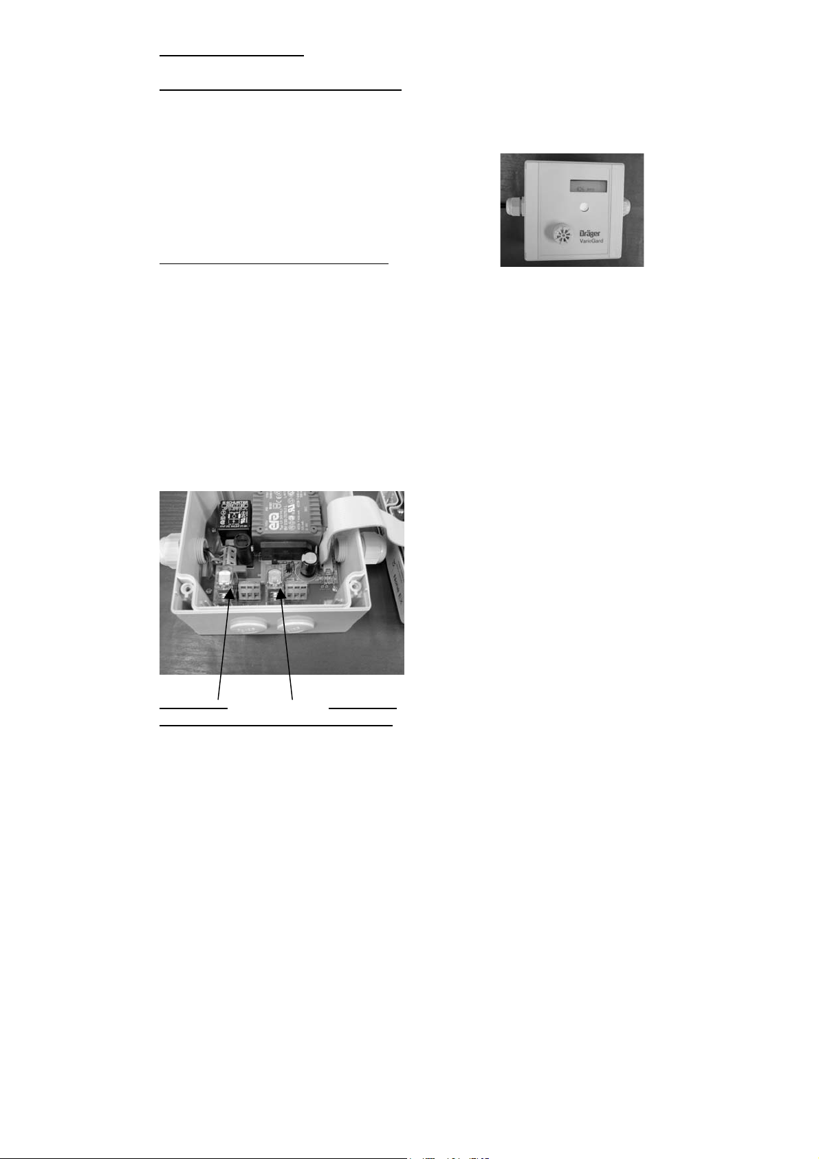
Verwendungszweck
VarioGard Transmitter ohne Netzteil
:
Zur stationären, kontinuierlichen Überwachung von Gas-Luftgemischen.
Mit 4... 20 mA Schnittstelle zum Anschluss an geeignete Zentralgeräte.
Mit Display zur Anzeige der Gaskonzentration am Messort.
VarioGard Transmitter mit Netzteil
:
Zur stationären, kontinuierlichen Überwachung von Gas-Luftgemischen
Mit Display zur Anzeige der aktuellen Gaskonzentration am Messort.
Zwei integrierte Relais, zum automatischen Einleiten von Gegenmaßnahmen
(z. B. Zuschaltung einer Lüftung und Aktivierung einer Blitzleuchte).
Betrieb unabhängig von einem Zentralgerät möglich.
Serienmäßig ohne 4.. 20 mA Schnittstelle. Die Schnittstelle ist als Zubehör
erhältlich und kann nachgerüstet werden.
Ebenfalls als Zubehör erhältlich: räumlich abgesetzte Fernanzeigeeinheit mit
Voralarm–LED, Hauptalarm-LED, Funktions-LED sowie einer Hupe (s.
Bestellliste).
Relais A2
Relais A1
Hauptalarm Voralarm
Seite 4
Page 5

In Verbindung mit einem Zentralgerät:
Warnung vor dem Erreichen gefährlicher Gaskonzentrationen.
Automatische Einleitung von Gegenmaßnahmen (z. B. Zuschaltung einer
Lüftung).
Warnung bei Gerätefehlern.
Bemerkung zur Ansteuerung mehrerer Messköpfe durch eine Zentrale
:
Bitte beachten Sie, dass ein Messkopf bis zu 250 mA Strom aufnehmen
kann.
Aus diesem Grund wird es z. B. bei der VarioGard Zentrale (auch im
Verbund mit einem Konvertermodul) notwendig, dass ein externes Netzteil
Verwendung findet, wenn mehr als zwei Messköpfe angeschlossen werden
sollen.
In diesem Fall empfehlen wird, je nach Anzahl der Messköpfe, zwei Netzteile:
Typ Anzahl Messköpfe
Netzteil
24VAC, 5A
Netzteil
24 VAC,
10A
Bis zu 10
Messköpfen
Bis zu 20
Messköpfen
Kein Betrieb in explosionsgefährdeten Bereichen
Der Transmitter ist nicht für den Betrieb in explosionsgefährdeten Bereichen
zugelassen.
Seite 5
Page 6

Transmitter installieren
Installation der Anlage durch geschultes Fachpersonal.
Montageort der Transmitter entsprechend den anzuwendenden Vorschriften
so wählen, dass das im zu überwachenden Bereich austretende Gas durch
den Transmitter rechtzeitig und sicher erfasst wird.
Zum Erreichen einer maximalen Schutzwirkung richtigen Montageort wählen.
Die freie Luftzirkulation um den Transmitter herum darf nicht behindert sein.
Der Montageort des Transmitters ist so nah wie möglich am Ort der
möglichen Leckstelle zu wählen:
Zur Überwachung von Gasen oder Dämpfen, die schwerer als Luft sind, ist
der Transmitter so nah wie möglich am Boden anzubringen.
Die örtlichen Luftströmungsverhältnisse sind zu berücksichtigen. Den
Transmitter an einem Ort anbringen, wo mit der höchsten Gaskonzentration
zu rechnen ist.
Bei weitläufigen Räumen kann auch eine Installation mehrerer Transmitter
notwendig sein.
Transmitter befestigen
3
Abdeckstreifen (1) vom Oberteil abnehmen.
Die vier Schrauben (2) am Gehäuseoberteil lösen
und Oberteil abnehmen
Befestigung mit vier Schrauben (3) durch das Gehäuse
3
Zum Schutz des Transmitters vor mechanischen Beschädigungen kann ein
Schutzgitter montiert werden (s. Bestellliste).
Bei der Montage auf unebenen Flächen sind Verspannungen des Gehäuses
zu vermeiden!
Der VarioGard Transmitter enthält einen empfindlichen optischen Sensor.
Starke mechanische Verspannungen des Gehäuses können seine
Messgenauigkeit reduzieren.
Seite 6
Page 7
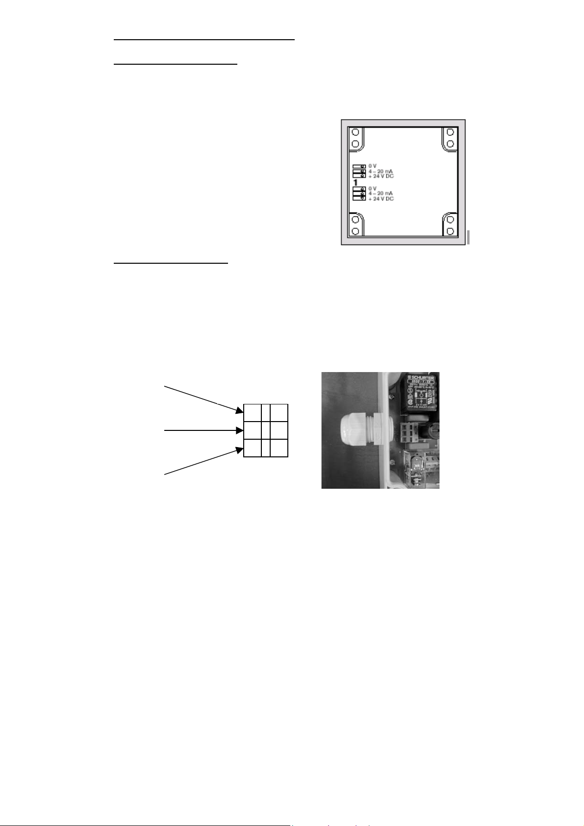
Elektrische Anschlüsse installieren
Transmitter ohne Netzteil:
Verlegung und Anschluss der elektrischen Installation des Transmitters nur
von einem Fachmann unter Beachtung der einschlägigen Vorschriften.
3-adrige Leitung z. B. NYM mit einem
Leitungsquerschnitt 3 x 0,5 mm
2
mm
verwenden.
Maximaler Bürdenwiderstand ≤ 500 Ω;.
Kontaktbelegung beachten, Anschluss über
Steckklemmblock im Oberteil.
Transmitter mit Netzteil:
Verlegung und Anschluss der elektrischen Installation des Transmitters nur
von einem Fachmann unter Beachtung der einschlägigen Vorschriften.
Der Transmitter mit Netzteil, ohne Schnittstelle benötigt nur eine
Stromversorgung (230VAC, 50/60 Hz).
Beim Anschluss an ein Zentralgerät wird die Schnittstelle (4.. 20 mA)
benötigt, welche optional erhältlich ist (s. Bestellliste).
N
PE
L
2
bis 3 x 1,5
WAGO-Klemme
Seite 7
Page 8
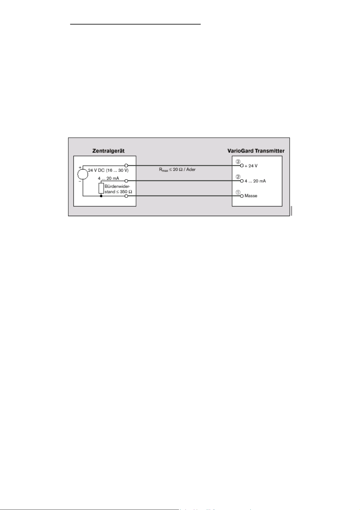
Schema zum Anschluss an ein Zentralgerät:
Belegung an einen der beiden Steckklemmblöcke (1) im Oberteil.
Die Klemmblöcke sind parallel geschaltet und können alternativ benutzt
werden:
24V DC (16 bis 30V) Versorgung und 4 bis 20 mA Signal
Klemmenbelegung:
0 V DC-Masse
4 bis 20 mA oder 0.. 20 mA oder 0.. 10 Volt-Signal (abhängig von der
Einstellung)
+24V DC Versorgung (siehe Seite 13).
Anschlussschema
Seite 8
Page 9
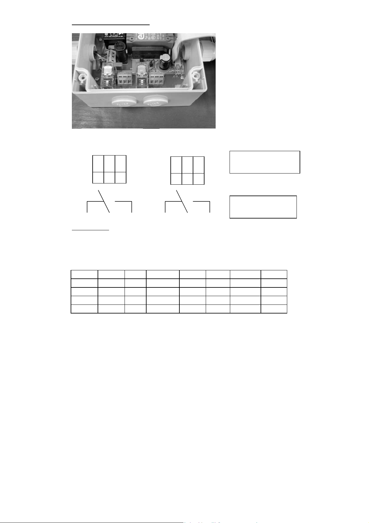
Anschlussschema Relais:
Hauptalarm
A2
Voralarm
A1
WAGO-Kontakt-
belegung
0 1 0 1
Relaisstatus
Schem.
Darstellung
Das Gerät mit Netzteil ist mit 2 Relais ausgestattet, mit denen z.B. externe
Signalgeräte geschaltet werden können.
Diese Relais sind den Alarmen A1 (Voralarm) und A2 (Hauptalarm)
zugeordnet. Beides sind stromlos geschlossene Relais.
Dip-Nr. 12 Aus Warmlaufen Fehler K<A1 A1 <=K<A2 K >= A2
Mode 0 Relais 1 0 0 0 0 1 1
Relais 2 0 0 0 0 0 1
Mode 1 Relais 1 0 0 0 1 0 0
Relais 2 0 0 0 1 1 0
A1, A2 = Vor- bzw. Hauptalarm
K = aktuelle Gaskonzentration
Seite 9
Page 10
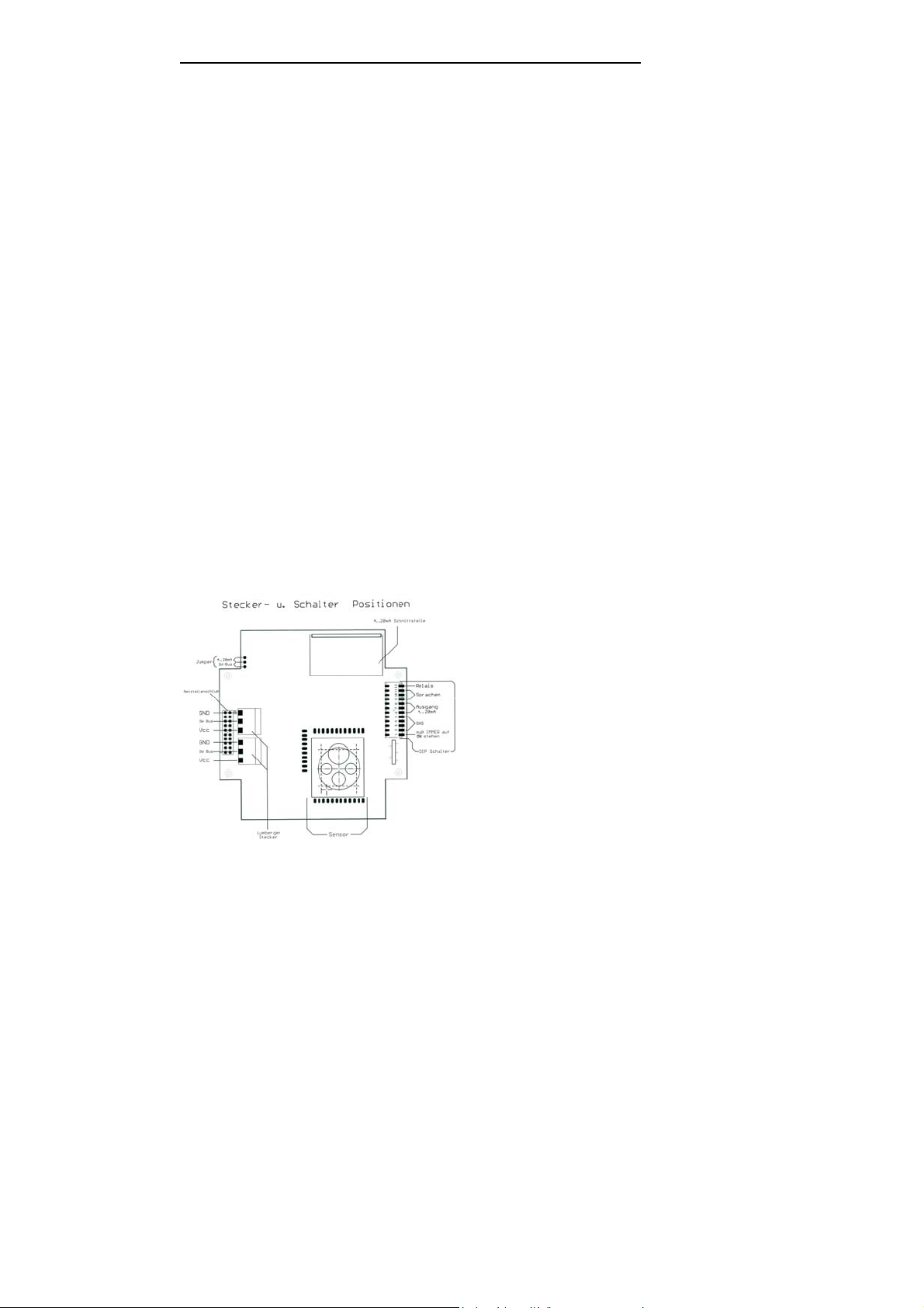
Stecker und Schalter auf der Platine und ihre Funktionen
Jumper 4..20 mA / DW-Bus
Dieser Jumper schaltet zwischen der standardisierten 4..20mA-Funktion und
dem Dräger Safety – spezifischen “DW” Bus (für Anschluss an VarioGardZentrale).
Netzteilanschluß
Eine 20-polige Stiftleiste, mit der das VarioGard-spezifische Netzteil mit zwei
Relais verbunden werden kann.
4..20 mA Schnittstelle
Steckplatine, die das 4..20 mA –Signal generiert und auf der zwischen Strom
(I) und Spannungausgang (U) umgeschaltet werden kann.
Dip-Schalter
Mit diesen Schaltern werden die spezifischen Funktionen des Sensors wie
Sprache /
Ausgang / Gasart eingestellt.
„Lumberger – Stecker“
Diese „Lumberger-Stecker“ dienen zum Anschluß an die 4..20mA
Schnittstelle eines externen Panels oder zur Versorgung bei nicht
vorhandenem internen Netzteil mit 16-30 VADC.
Sensors
Der Sensor ist das eigentliche Kernstück des Messfühlers , er wird über drei
Stiftleisten mit der Haupt-Platine verbunden und detektiert hochselektiv das
Gas.
Seite 10
Page 11
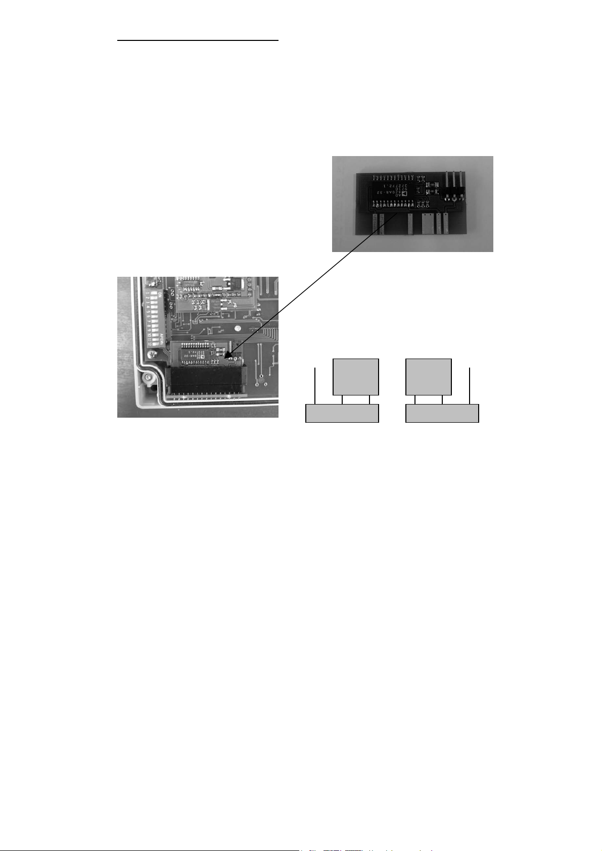
Zubehör Schnittstelle installieren (Best.-Nr. 8315839)
Die Installation von Zubehör nur von einem Fachmann unter Beachtung der
einschlägigen Vorschriften.
Den Transmitter von seiner Stromversorgung trennen und das
Gehäuseoberteil abnehmen.
Anschließend die 4.. 20 mA Schnittstelle auf den dafür vorgesehenen
Steckplatz aufstecken (siehe Zeichnung „Stecker – Schalterposition „ auf der
nachfolgende Seite).
.
Der Dip-Schalter hat auf die genaue Funktion
der 4..20 mA-Schnittstelle großen Einfluß,
daher ist es wichtig, vor Inbetriebnahme den
Abschnitt „ Einstellung DIP-SWITCH“ genau
zu lesen.
Achtung:
Die Voreinstellung ob
Spannungs (U)- oder
Strombetrieb (I) hängen von
der Jumper-Stellung auf der
4..20 mA Schnittstelle ab.
Voreinstellung I
I - Betrieb
U - Betrieb
Seite 11
Page 12

Transmitter in Betrieb nehmen
Der VarioGard IR-Transmitter ist bei Lieferung vorkalibriert und nach der
Installation sowie einer Einlaufzeit von etwa 5 Minuten des Sensors sofort
einsatzbereit.
Transmitter ohne Netzteil
Zur Vermeidung von Fehlalarmen die Alarmauslösung des Zentralgerätes
ggf. deaktivieren.
System mit Spannung versorgen. Der Transmitter geht in die Einlaufphase.
Die Einlaufphase wird durch die Ausgabe des Wartungssignals signalisiert.
Danach ist der Transmitter im normalen Messbetrieb.
Signalübertragung zur Zentrale und Alarmauslösung mit Prüfgas überprüfen.
Zum Aktivieren der Alarmauslösung am Zentralgerät das System ggf. wieder
in seinen normalen Betriebszustand versetzen.
Transmitter mit Netzteil
System mit Spannung versorgen. Der Transmitter geht in die Einlaufphase.
Die Einlaufphase wird durch die Ausgabe des Wartungssignals auf dem
Display signalisiert. Danach ist der Transmitter im normalen Messbetrieb.
Funktion des Transmitters mit Prüfgas prüfen.
Der Transmitter kann auch mit einem Zentralgerät betrieben werden. Hierfür
ist das Zubehör (Schnittstelle 4.. 20 mA, Best.-Nr. : 8315839) erforderlich.
Die Inbetriebnahme erfolgt dann wie bei dem Transmitter ohne Netzteil.
Seite 12
Page 13
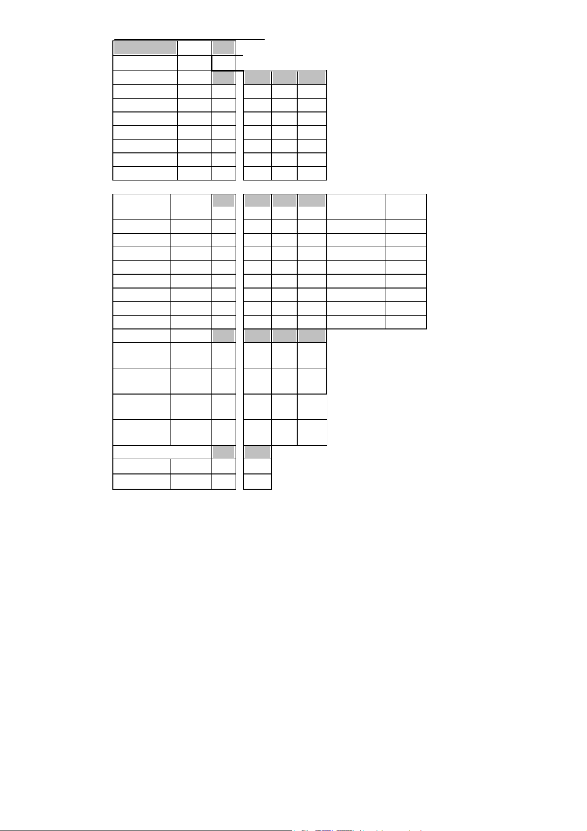
Einstellungen der Dip-Switches
DIP-Switch 1
Bus ON steht immer auf "ON"
Sprache
1
9 10 11
deutsch ON OFF OFF OFF
englisch ON ON OFF OFF
französisch ON OFF ON OFF
italienisch ON ON ON OFF
spanisch ON OFF OFF ON
holländisch ON ON OFF ON
frei ON OFF ON ON
4..20mA Stromschnittstelle
1 6 7 8 Warmlauf
Fehler
en
4.. 20 mA linear ON OFF OFF OFF 3,2mA 3,2 mA
4 .. 20 mA linear ON ON OFF OFF 0,8 mA 0,8 mA
0.. 20 mA linear ON OFF ON OFF 0 mA 0 mA
0 .. 20 mA linear ON ON ON OFF 24 mA 24 mA
4 .. 20 mA horiba ON OFF OFF ON 3,2 mA 3,2 mA
4.. 20 mA horiba ON ON OFF ON 0,8 mA 0,8 mA
0 .. 16 mA horiba ON OFF ON ON 0 mA 0 mA
0.. 10 V linear ON ON ON ON 0 V 0 V
Gas 1 2 3 4
Methan 99%
ON OFF OFF OFF
UEG
Buthan 99%
ON ON OFF OFF
UEG
Propan 99%
ON OFF ON OFF
UEG
Nonan 99%
ON ON ON OFF
UEG
Relais 1 12
Mode 0
Mode 1
(*2)
(*2)
ON OFF
ON ON *2 s. Kapitel Relaisstatus
Seite 13
Page 14

Betrieb
Der Transmitter überwacht kontinuierlich die Konzentration des explosiblen
Gases in der Umgebungsluft.
Liegt keine Störung vor, zeigt das Display die Konzentration des zu
überwachenden Gases an.
Die Messwertübermittlung an das Zentralgerät (Transmitter ohne Netzteil)
erfolgt über die 4 bis 20mA Schnittstelle.
Bei dem Transmitter mit Netzteil kann eine Signalübertragung an ein
Zentralgerät nur dann erfolgen, wenn eine Schnittstelle (s. Bestellliste)
installiert wurde. Ansonsten erfolgt eine Messwertanzeige nur über das
Display!
Um einen einwandfreien Messbetrieb zu gewährleisten, darf der Gaszutritt
zum Transmitter nicht verschlossen werden!
Wartung und Störung
Verhalten nach Stromausfall
Nach einem Stromausfall wird, wenn die Versorgungsspannung wieder
anliegt, die Einlaufphase erneut durchlaufen.
Nach dieser Zeit kehrt die Anlage automatisch in den normalen Messbetrieb
zurück.
Verhalten bei Störung
Wenn eine Störung am Transmitter auftritt, erscheint auf dem Display
blinkend der Schriftzug „Fehler Nr.“.
Dieser Fehlercode dient dem DrägerService zur Fehleridentifizierung und behebung.
Bitte beachten Sie, dass der Transmitter keine Gaskonzentrationen
mehr anzeigt und detektiert, solange der Fehler nicht behoben ist.
Seite 14
Page 15

Verhalten bei Alarm
Allgemein:
Im Falle einer Alarmauslösung durch eine zu hohe Gaskonzentration wird
entweder der Voralarm oder auch der Hauptalarm ausgelöst. Im Display
erscheint abwechselnd mit der Anzeige der Gaskonzentration blinkend der
Schriftzug „Voralarm“ bzw. „Hauptalarm“.
Transmitter ohne Netzteil:
Über die Schnittstelle wird der voreingestellte Wert für den Voralarm bzw.
Hauptalarm an ein Zentralgerät übertragen (z.B. Hauptalarm 18mA).
Transmitter mit Netzteil:
Dem Voralarm und dem Hauptalarm ist je ein Relais zugeordnet, über
welche Gegenmaßnahmen getroffen werden können (z. B. Zuschaltung von
Zusatzlüftungen). Bei den Relais handelt es sich um NC’s (bei Stromausfall
geschlossener Kontakt).
Alle Alarme sind nicht selbsthaltend und nicht quittierbar.
Seite 15
Page 16

Übersicht Anzeigemöglichkeiten
Beispiel: Transmitter IR - Ex
Warmlaufen (blinkend)
W A R M L A U F E N
- - - % U E G
Normaler Betrieb
0 . 0 % U E G
Voralarm (blinkend)
> V O R A L A R M
2 0 % U E G
Hauptalarm (blinkend)
> H A U P T A L A R M
5 0 % U E G
Störung (blinkend)
F E H L E R N R X X
- - - % U E G
Seite 16
Page 17

Instandhaltung
Instandhaltungsintervalle
Sichtkontrolle
Mindestens einmal in 3 Monaten, zur Feststellung der Betriebsbereitschaft,
VarioGard IR auf mechanische Beschädigung und ungehinderten Gaszutritt
zum Sensor prüfen.
Wiederholungsprüfung
Je nach Anforderung der örtlichen Vorschriften und Bestimmungen.
Bei Bedarf
(z. B. Fehlermeldungen)
Oberteil des Transmitters wechseln. Kalibrierte Oberteile sind im Austausch
durch den DrägerService erhältlich. Für den Abschluss eines ServiceVertrages sowie für Instandsetzungen empfehlen wir den DrägerService.
Seite 17
Page 18

Technische Daten
Version ohne Netzteil Version mit Netzteil
Größe (BxHxT, mm)
Gewicht
Betriebsspannung
Alarmschwellen
Anzeige
Alarmfunktionen
-Relais
-optisch
-akustisch
-Quittierung
Sensortyp
Messbereich
Ansprechzeit (T90)
Auflösung
MTBF
Betriebstemperatur
Lagertemperatur
Feuchtigkeit
Luftdruck
Anschlusskabel
Gehäuseschutzart
Zulassung
120x145x100 120x145x100
600 gr. 2 Kg
12.. 30 VDC 230, 115 VAC +/- 10 %,
50 / 60 Hz
werkseitig eingestellt auf:
Voralarm: 20 % UEG
Hauptalarm: 50 % UEG
einstellbar zwischen
Voralarm: 0 – 99 % UEG
Hauptalarm:0- 99 % UEG
durch den DrägerService
LCD, 2 Zeilen Display,
hintergrundbeleuchtet
werkseitig eingestellt auf:
Voralarm: 20 % UEG
Hauptalarm: 50 % UEG
einstellbar zwischen
Voralarm: 0 – 99 % UEG
Hauptalarm:0 – 99 % UEG
durch den DrägerService
LCD, 2 Zeilen Display,
hintergrundbeleuchtet
nur über Zentrale 2 Relais (5A 230VAC)
nur über eine Zentrale Extern über Relais möglich
nur über eine Zentrale Extern über Relais möglich
Zentrale, bzw. über
Remote-Panel
Zentrale, bzw. über
Remote-Panel
NDIR, Temperatur kompensierter Infrarotmesskopf, 4Strahl-Messverfahren
0 – 99 % UEG
< 40 Sek.
1 % UEG Gem. EN 50 194
10 Jahre
-30 bis + 50°C
-30 bis +60 °C
0 bis 99 % rel. F. keine Kondensation
700 – 1300 hPa
z.B. NYM 3 x 0,75 mm
2
IP54 (Gehäuse)
CE gemäss 73/23 EEC, 89/336 EEC
Seite 18
Page 19

Messprinzip
g
IR EX-Transmitter
Der VarioGard IR Ex-Transmitter ist ein Messwandler zur Überwachung der Konzentration von
ausgesuchten brennbaren Gasen und Dämpfen in der Umgebungsluft nach dem Prinzip der
Absorption von Infrarotstrahlung.
Die zu überwachende Umgebungsluft gelangt durch Diffusion in den optischen IR- Sensor, der
auf einer Leiterplatte befestigt ist.
Die Leiterplatte enthält einen Mikrocontroller zur Signalverarbeitung, einen einstellbaren Vorverstärker für die Detektorsignale sowie je nach Version, eine 4 bis 20 mA Schnittstelle zum
Anschluss an ein Zentralgerät.
Das Licht der beiden Lampen 1 und 2 im Sensor wird über einen Strahlteiler 3 auf Messdetektor 4 und Referenzdetektor 5 gleichmäßig aufgeteilt.
Anteile von brennbaren Gasen und Dämpfen in der Um
der Strahlung bei der Messwellenlänge und damit zu einer Signalabnahme des Messdetektors.
Das Licht der beiden Lampen wird mit unterschiedlichen Frequenzen moduliert. Das Licht von
Lampe 1 dient zur Messung der Gaskonzentration, das von Lampe 2 zur Normierung der
Detektoren. In den Detektoren entsteht somit ein Überlagerungssignal beider Lampen, das
anschließend im Mikroprozessor ausgewertet wird. Somit entstehen vier Einzelsignale.
Aus den Quotienten dieser Signale wird die Gaskonzentration ermittelt. Der Quotient dieser
Signale ist unabhängig von der Intensität der Lampen und der Empfindlichkeit der Detektoren.
Dies garantiert eine gute Langzeit- und Temperaturstabilität des Sensors.
Damit eine Beeinflussung der Messsignale durch hohe Luftfeuchtigkeit ausgeschlossen werden kann, ist eine Heizung außen an der Küvette installiert, welche die Temperatur in der
Küvette über die Außentemperatur anhebt.
ebungsluft führen zu einer Absorption
Seite 19
Page 20

Bestellliste
Transmitter
Transmitter VarioGard, Ir-HC ohne Netzteil, mit Schnittstelle (4.. 20 mA)
Best.-Nr. : 83 15 926
Transmitter VarioGard IR-HC , mit Netzteil, ohne Schnittstelle
Best.-Nr. : 83 15 927
Transmitter VarioGard IR-HC, mit Netzteil, ohne Schnittstelle, mit
Fernanzeige
Best.-Nr. : 8315928
Zubehör
Schnittstelle (4.. 20 mA), für Netzteilversion
Best.-Nr. : 83 15 839
Fernanzeige (Remote-Panel)
Best.-Nr. : 83 16 469
Kabeleinführung M 20x1,5 (Set 10 Stück)
Best.-Nr. : 83 15 420
Schutzgitter Transmitter (Edelstahl)
Best. -Nr.: 83 14 652
Seite 20
Page 21

Instructions for Use
Seite 21
Page 22

Content
For Your Safety 23
Strictly follow the Instructions for Use 23
Maintenance 23
Liability for Function and Damage 23
Intended Use 24
VarioGard Transmitter without power supply 24
VarioGard Transmitter with Power Supply 24
In Conjunction With a Controller 25
Comment on Controlling Several Measuring Heads by
One Controller: 25
Installation of the Securing the Transmitter 26
Installation of the Transmitter 26
Securing the Transmitter 26
Installation of the Electrical Connections 27
Transmitter Without Power Supply 27
Transmitter With Power Supply: 27
Connection Diagram for Connection to a Controller 28
Connection Diagram, Relays 29
Connectors and switches on the pcb and their function 30
Installation of the optional Interface 31
Putting the Transmitter into Operation 32
Transmitter Without Power Supply 32
Transmitter With Power Supply 32
Adjustment of the Dip Switch 33
Operation 34
Maintenance and Faults 34
Behaviour Following Power Failure 34
Behaviour Following a Fault 34
In Case of an Alarm 35
Gerneral Information 35
Transmitter Without Power Supply: 35
Transmitter With Power Supply: 35
Overview of Display Possibilities 36
Maintenance 37
Maintenance Intervals 37
Technical Data 38
Principle of Measuring 39
Order List 40
Seite 22
Page 23

For Your Safety
Strictly follow the Instructions for Use
Every operation using the equipment assumes that the information in the
operating manual has been read and observed.
The equipment may only be used for the intended use described.
Maintenance
Repairs to the equipment may only be carried out by properly trained
personnel.
Only use original parts procured from Dräger for maintenance.
We recommend the conclusion of a service contract with DrägerService for
repairs.
Refer to the Chapter "Maintenance Intervals".
Liability for Function and Damage
Liability for the functionality of the unit is transferred to the proprietor or the
operator when the unit has been improperly serviced or has been operated
for a purpose which does not comply with the intended use.
Dräger Safety AG & Co. KGaA is not liable for damage caused by failure to
observe the information provided.
The warranty and liability conditions set out in the General Terms of Business
applied by Dräger Safety AG & Co. KGaA are not extended by this
information.
Do not operate in potentially explosive areas
The unit has not been approved for operation in potentially explosive
atmospheres.
Seite 23
Page 24

Intended Use
VarioGard Transmitter Without Power Supply
:
– For stationary, continuous monitoring of explosive gas-air mixtures.
– With 4 ... 20 mA interface for connection to suitable controllers.
– With display to indicate the gas concentration at the measuring
location.
VarioGard Transmitter With Power Supply
:
– For stationary, continuous monitoring of explosive gas-air mixtures.
– With display to indicate the current gas concentration at the measuring
location.
– Two integrated relays for the automatic initiation of countermeasures (e.g.
activation of additional ventilation and a flashing lamp).
– Possible independent operation from a controller.
– Options: (see accessories list)
– 4 .. 20 mA Interface
– Panel with LED’s for function, pre alarm and main alarm
Alarm A2 Alarm A1
Main Alarm Pre Alarm
Seite 24
Page 25

In Conjunction With a Controller:
– Warning prior to reaching explosive gas concentrations.
– Automatic initiation of countermeasures (e.g. activation of additional
ventilation).
– Warning in the case of equipment faults.
Comment on Controlling Several Measuring Heads by One Controller
:
Please note that a transmitter can have a current consumption up to
250 mA.
For this reason, it is necessary, e.g. in the case of the VarioGard controller
(even in connection with a converter module), that an external power supply
is used if more than two transmitters are to be connected (refer to table).
Type No. of transmitters
Power supply
24VDC, 5A
Power supply
24 VDC, 10A
Up to 10 transmitters
Up to 20 transmitters
Do Not Operate in Potentially Explosive Areas
The transmitter is not approved for use in potentially explosive areas.
Seite 25
Page 26

Installation of the Transmitter
The system may only be installed by properly trained personnel.
Select the installation location of the transmitter according to the applicable
regulations so that any gas escaping in the area to be monitored is detected
reliably and in good time.
– Select the correct installation location to ensure maximum protection. No
obstacles should prevent the free circulation of air around the transmitter.
– The installation location of the transmitter should be selected so that it is
as near as possible to potential gas leaks.
• In order to monitor for gases and vapors with a density greater than
air (e.g. NONANE ), the transmitter should be mounted as near as
possible to the floor.
• Take local air circulation behavior into account. Mount the transmitter
in a location at which the highest concentrations of gas can be
expected.
• In the case of large rooms, it may be necessary to install several
transmitters.
Securing the Transmitter
1. Remove the covering strips (1) from the cover.
2. Remove the four screws (2) from the upper
housing and remove the cover.
3. Secure with four screws (3) through the housing
(refer to Page 15 for the drill hole template).
When installing on uneven surfaces, prevent distortion of the housing.
The VarioGard transmitter contains a sensitive optical sensor.
Strong mechanical distortions of the housing could impair its measuring
accuracy.
Seite 26
Page 27

Installation of the Electrical Connections
Transmitter Without Power Supply:
The electrical installations may only be laid and connected by properly
trained personnel observing the applicable
regulations.
– Use 3-wire lines, e.g. NYM with a line
cross-section of 3 x 1.5 mm
– Maximum load resistance ≤ 500 Ω.
– Observe contact assignment, connection
via plug-in terminal strip in the cover.
Transmitter With Power Supply:
The electrical installations may only be laid and connected by properly
trained personnel observing the applicable regulations.
The transmitter with power supply unit, without an interface, only requires a
power supply (230VAC,
50 Hz).
For the connection to a controller, the interface (4 .. 20 mA) is necessary
which is available on option (Order No.: 8315839).
2
.
Connector
N
PE
L
Seite 27
Page 28

Connection Diagram for Connection to a Controller:
Assignment at one of the two plug-in terminal strips (1) in the cover.
The terminal strips are switched parallel and can be used alternatively:
24V DC (16 to 30V) supply and 4 to 20 mA signal
Terminal assignment:
0 V DC ground
4 to 20 mA signal or 0 to 20 mA or 0..10 Volt
+24V DC supply
Connection diagram
Seite 28
Page 29

Connection Diagram, Relays
main alarm pre alarm
0 1 0 1
Relay status
The unit with power supply have 2 relays on board, where signal devices can
be connected. The relay terminals are potential free.
The relays are assigned to alarm A1 (pre alarm, adjusted to 20% LEL) and
alarm A2 (main alarm, adjusted to 40% LEL).
Dip-Nr.
12
Mode 0 Relay 1
Relay 2
Mode 1 Relay 1
Relay 2
No
Power
Warm up Fault K<A1 A1 <=K<A2 K >= A2
0 0 0 0 1 1
0 0 0 0 0 1
0 0 0 1 0 0
0 0 0 1 1 0
A1, A2 = pre / main alarm
K = current gas concentrations
Seite 29
Page 30

Connectors and switches on the pcb and their function
Jumper 4..20 mA / DW-Bus
This jumper switches between the 4 to 20 mA function and the Dräger bus to
connect it to the VarioGard central unit.
Power supply
This 20 pin strip connects the transmitter electronic with the VarioGard power
supply and two relays
4..20 mA Interface
This pcb generates 0 to 4 mA or 4 to 20 mA or 0 to 10 V signal. A jumper
can switch between current and voltage output.
Dip-switch
This switches are used for sensor setup. It selects the language, the kind of
current /voltage output curve and the typ of gas.
„Lumberger – Connector“
This Lumberger – Connector“ connects 4 to 20 mA Interface to a external
panel or provided the sensor with external 16 to 30 VDC.
Sensors
This sensor is the heart of the transmitter. It is connect over three strips with
the main pcb and detects highly selective the type of gas.
Seite 30
Page 31

Installation of the optional interface (Order No. 8315839)
The installation of options should only be carried out by properly trained
personnel observing the applicable regulations.
Disconnect the transmitter from its power supply and remove the upper
housing.
Then connect the 4 .. 20 mA interface in the slot provided (refer to drawing).
The Dip-Switch has a big effect on the
4 to 20 mA output. Therefore it is necessary
toread the article about the “Dip-switches”
first.
Attention:
The jumper on the 4 to 20 mA
card selects between voltage (U)
and current (I) output mode. The
default setting is current (I).
I - Betrieb
U - Betrieb
Seite 31
Page 32

Putting the Transmitter into Operation
The VarioGard transmitter is calibrated before supply and is immediately
ready for use following installation and a sensor warm-up phase of about 10
minutes.
Transmitter Without Power Supply
• To prevent false alarms, deactivate the alarm triggering function of the
controller, if necessary.
Switch on the power supply to the system. The transmitter enters its warm-up
phase. The warm-up phase is indicated by the issue of a maintenance signal.
The transmitter is then in normal measuring mode.
• Check signal transmission to the controller and alarm triggering with test
gas.
• To activate the alarm triggering function on the controller, reset the
system to normal operating status, if necessary.
Transmitter With Power Supply
• Switch on the power supply to the system. The transmitter enters its
warm-up phase. The warm-up phase is indicated by the issue of a
maintenance signal. The transmitter is then in normal measuring mode.
• Check the function of the transmitter and alarm triggering with test gas.
The transmitter can also be operated via a controller. In this case, the
optional 4 .. 20 mA interface, order no. 8315839, is required.
Putting into operation is then the same as for the transmitter without power
supply.
Seite 32
Page 33

Adjustment of the Dip Switches
DIP-Switch 1
Bus ON Always "ON"
Language
1 9 10 11
German ON OFF OFF OFF
English ON ON OFF OFF
French ON OFF ON OFF
Italian ON ON ON OFF
Spanish ON OFF OFF ON
Dutch ON ON OFF ON
turkish ON OFF ON ON
4..20mA Current Interface
1 6 7 8 Warm-up
4.. 20 mA linear ON OFF OFF OFF 3,2mA 3,2 mA
4 .. 20 mA linear ON ON OFF OFF 0,8 mA 0,8 mA
0.. 20 mA linear ON OFF ON OFF 0 mA 0 mA
0 .. 20 mA linear ON ON ON OFF 24 mA 24 mA
4 .. 20 mA horiba ON OFF OFF ON 3,2 mA 3,2 mA
4.. 20 mA horiba ON ON OFF ON 0,8 mA 0,8 mA
0 .. 16 mA horiba ON OFF ON ON 0 mA 0 mA
0.. 10 V linear ON ON ON ON 0 V 0 V
Gas 1 2 3 4
Methane 99% UEG ON OFF OFF OFF
Buthane 99% UEG ON ON OFF OFF
Propane 99% UEG ON OFF ON OFF
Nonane 99% UEG ON ON ON OFF
Relay 1 12
Mode 0
Mode 1
(*2)
(*2)
ON OFF
ON ON
Error
UEG / LEL
Mode 0
Mode 1
(*1)
(*1)
1 5
ON OFF UEG = default
ON ON LEL
Seite 33
Page 34

Operation
The transmitter continuously monitors the concentration of potentially
explosive gas in the ambient air.
– If no fault has occurred, the display indicates the concentration of the gas
being monitored.
– The measured value is transferred to the controller (transmitter without
power supply) via the 4 to 20mA interface.
– In the case of a transmitter with power supply, signal transmission to the
controller can only occur when an interface has been installed
(optionally available 4..20 mA interface, order no.: 8315839). Otherwise,
the measured value is only indicated in the display.
In order to ensure problem-free measuring operation, gas access to the
transmitter must not be blocked!
Maintenance and Faults
Behavior Following Power Failure
Following a power failure, the warm-up phase is initiated again when the
power supply returns.
When the warm-up time is completed, the unit automatically switches to
normal measuring mode.
Behavior Following a Fault
When a fault occurs in the transmitter, the text “Error Code” appears in the
display.
This error code helps the Dräger Service to identify the fault and eliminate it.
Please note that the transmitter no longer displays or detects any gas
concentrations until the fault has been cleared.
If the error code appears, please contact the nearest Dräger Service
representative, stating the error code. The telephone numbers are listed at
the end of this instruction manual.
Seite 34
Page 35

In Case of an Alarm
General Information:
When an alarm is triggered as a result of a too high gas concentration, either
the pre alarm or the main alarm are issued. The display indicates the actual
gas concentration alternately flashing with the “pre alarm” or “main alarm”.
Transmitter Without Power Supply:
The preset value for the pre alarm or main alarm is transferred to a controller
via the interface (e.g. main alarm 18mA).
Please note that the VarioGard IR Ex switches currentless as soon as a main
alarm is triggered.
Transmitter With Power Supply:
The pre alarm and main alarm are each assigned a relay via which
countermeasures can be initiated (e.g. activation of additional ventilation).
The relays are NCs (= normally closed contacts; when no current is applied,
the contact is closed).
Please note that the VarioGard IR Ex switches currentless as soon as a main
alarm is triggered.
All alarms are non-latching alarms.
Seite 35
Page 36

Overview of Display Possibilities
Example: Transmitter 100 % LEL Methane:
Warming-Up (flashing)
W A R M I N G U P
- - - % L E L
Normal Operation
1 0 % L E L
Pre Alarm (flashing)
> P R E A L A R M
2 2 % L E L
Main Alarm (flashing)
> M A I N A L A R M
4 5 % L E L
Error Code (flashing)
E R R O R N O X X
- - - % L E L
Seite 36
Page 37

Maintenance
Maintenance Intervals
Visual Inspection
At least once every three months check that the unit is ready to operate,
check it for signs of mechanical damage and ensure that the gas can access
the sensor uninhibited.
Recurrent Tests
According to local regulations and directives.
We recommend annual maintenance by Dräger Service.
We also recommend Dräger Service for any necessary repairs and
conclusion of a service contract.
Seite 37
Page 38

Technical Data
Gas Type Methane Methane
Dimensions
(WxHxD,mm)
Weight
Operating voltage
Alarm thresholds
Alarm conditions
Display
Alarm functions
relay
optical
audible
acknowledgement
Sensor type
Measuring range
Response time (T90)
Resolution
MTBF
Operating temperature
Storage temperature
Relative humidity
Air pressure
Connection cable
Housing, degree of
protection
Approvals
Without power supply With power supply
120x145x100 120x145x100
600 gr. 2 kg
12 .. 30 VDC 230, 115 VAC +/- 10%,
50 / 60 Hz
Factory settings:
Pre alarm: 20% LEL;
Main alarm: 40% LEL
Adjustment range:
Pre alarm: 0-99% LEL;
Main alarm: 0-99% LEL
0%LEL < A1 < A2 <
99%LEL
LCD, 2-line dot matrix
display,
back-lighting
Factory settings:
Pre alarm: 20% LEL;
Main alarm: 40% LEL
Adjustment range:
Pre alarm: 0-99% LEL;
Main alarm: 0-99% LEL
0%LEL < A1 < A2 <
99%LEL
LCD, 2-line dot matrix
display,
back-lighting
Only via controller 2 relays (5A 230VAC)
Only via controller External via relay possible
Only via controller External via relay possible
Controller Controller
NDIR, temperature compensated infrared sensor, 2-
beam measuring method
0 – 99% LEL
< 40 sec.
+/- 1% LEL Complying with EN50194
10 years
-30 to + 50°C
-30 to +60 °C
0 to 99% rel. humidity, no condensation
900 – 1100 hPa
E.g. NYM 3 x 0,75 mm
2
IP54 (housing)
CE complying with 73/23 EEC, 89/336 EEC
Seite 38
Page 39

Principle of Measuring
Ex-Transmitter
The VarioGard IR Ex Transmitter is a measuring transformer for monitoring
the concentration of explosive gases in the ambient air according to the
principles of absorption of infra-red radiation.
The ambient air to be monitored diffuses and accesses the optical exsensor which is mounted on a printed circuit board.
The printed circuit board contains a microcontroller for processing signals,
an adjustable pre-amplifier for the detector signals and a 4 to 20 mA
interface for connection to a controller.
The light from the two lamps 1 and 2 in the sensor is evenly distributed via
a beam splitter 3 onto the measuring detector 4 and reference detector 5.
Parts of the gases to be detected in the ambient air cause an absorption of
the beam at the measuring wavelength and, thus, to a signal reduction of
the measuring detector.
The light from the two lamps is modulated at different frequencies. The light
from Lamp 1 serves for measuring the gas concentration, that from Lamp 2
for referencing the detectors. Thus, a superimposed signal from both lamps
is produced in the detectors which is evaluated in the microprocessor. As a
result, four individual signals are generated.
The gas concentration is determined based on the ratio of these signals.
The ratio of the signals is independent of the intensity of the lamps and
sensitivity of the detectors. This ensures a long service life and temperature
stability of the sensors.
In order to rule out high relative humidity influencing the measured signal, a
heating source is installed on the outside on the cell which raises the
temperature inside the cell above that outside.
Seite 39
Page 40

Order List
Transmitter
Transmitter VarioGard IR Ex, without power supply, with interface (4 ..
20 mA)
Order No.: 83 15 926
Transmitter VarioGard IR Ex, with power supply, without interface
Order No.: 83 15 927
Accessories
Interface (4 .. 20 mA), for power supply version
Order No.: 83 15 839
Cable entry M 20x1,5 (set of 10 pieces)
Order No.: 83 15 420
Protective grid, transmitter (stainless steel)
Order No.: 83 14 652
Spare Parts
Spare parts and exchange parts for repairs can only be purchased from
DrägerService.
Please call your nearest DrägerService representative as necessary.
Seite 40
Page 41

Branches in
Federal Republic of Germany
Vertrieb Anlagenbau
Stationäre Gasmesstechnik
Munich
Leonhardsweg 4
82008 Unterhaching
Tel.:(0 89) 61 52 03 - 13
FAX (0 89) 61 52 03 - 10
Krefeld
Kimpler Strasse 284
47807 Krefeld
Tel.:(0 21 51) 37 35 - 48
FAX (0 21 51) 37 35 - 35
Leipzig
An der Harth 10 B
04416 Markkleeberg
Tel.:(03 41) 35 34 - 673
FAX (03 41) 35 34 - 672
Lübeck
Revalstrasse 1
23560 Lübeck
Tel.:(04 51) 882 - 4722
FAX (04 51) 882 - 4724
Seite 41
Page 42

International
Branches
Draeger Industrie S.A.
3c, Route de la Fédération
F-67025 Strasbourg Cedex
France
TeL.:+ 33 388 40 76 76
FAX :+ 33 388 40 76 67
Draeger Ltd.
Ullswater Close
Kitty Brewster Industrial Estate
Blyth, Northumberland NE24 4RG
United Kingdom
Tel.:+ 44 1670 352 891
FAX + 44 1670 356 266
Draeger Safety, Inc.
10450 Stancliff
Suite 220
Houston, TX 77099
U.S.A.
y +1 281 498 1082
FAX +1 281 498 5190
Draeger South East Asia Pte, Ltd.
67, Ayer Rajah Crescent #06-03
SGP-139950 Singapore
Singapore
Tel.:+ 65 872 92 88
FAX + 65 773 20 33
Seite 42
Page 43

Beijing Fortune Draeger Safety
Equipment Co., Ltd.
Jixiang Lu. B Area
Beijing Tianzhu Airport Industrial Zone
Houshayu
Shunyi Country
Beijing, 101300
P.R. China
Tel.:+ 86 10 69498000
FAX + 86 10 69498006
Dräger Safety AG & Co KGaA
st
1
Edition –
All Rights Reserved
Dräger Safety AG & Co
KGaA
06.00 – Edition –06- 2003
All Rights Reserved
Seite 43
 Loading...