

Dräger REGARD 4208797, REGARD 4208839, REGARD 4208840 Installation, Operation And Maintenance Manual
Issue 1 – November 2006
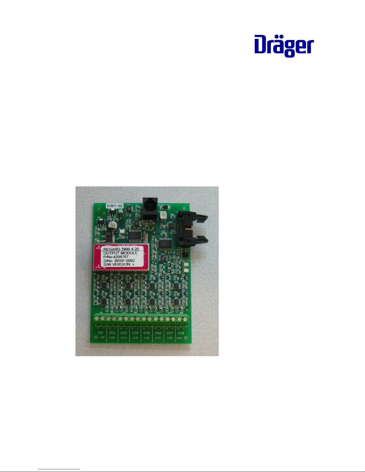
REGARD 3900
4-20mA output module
Installation, operation and maintenance

2 Issue 1 – November 2006
FOR YOUR SAFETY
Follow the instructions
Read this manual before installing the module.
Maintenance
The equipment must be inspected and serviced regularly by trained personnel. Keep
a record of inspections and servicing.
Repairs of this equipment should only be carried out by competent personnel.
We recommend that either a training course or service contract is obtained from
Draeger and that all repairs are carried out by them.
If the system is being used to monitor flammable gases/vapours and/or oxygen, refer
to EN 50073 and/or local regulations.
Not for use in areas where explosion hazards are possible
This equipment is not approved or certified for installation in potentially explosive
atmospheres.
Liability for proper function or damage
Liability for proper function of the equipment is irrevocably transferred to the owner or
operator to the extent that the equipment is serviced or repaired by personnel not
employed or authorised by Draeger, or if the equipment is used in a manner not
conforming to its intended use.
Draeger Safety UK Limited can not be held responsible for any damage caused by
non-compliance with the above recommendations. The warranty and liability
provisions of the terms and conditions of sale and delivery of Draeger Safety UK
Limited are likewise not modified by the recommendations given above.

Issue 1 – November 2006 3
INTENDED USE
• For remote indication or recording of gas levels.
• Not for control of counter-measures against risk of explosion. The 4-20mA output
module is not included in the scope of the Regard 3900 ATEX EC-type
examination.
The module must be mounted within the Regard 3900 control unit enclosure. Up to
four modules can be installed if there is space in the enclosure.
• Do not mount the module outside the 3900 enclosure.
• Do not extend the 3900 ribbon cable or use a longer ribbon cable, in order to
install output modules remote from the input module(s).
The module can be used in Regard 3910 systems. Do not exceed 2m ribbon cable
length.
The Regard 3900 4-20mA output module will not work with Regard 3800.
DESCRIPTION
The module has eight outputs, electrically isolated from the Regard 3900 system.
Each output is a current source and will only work when connected to a passive load.
Each output has two terminals:
+ output
– module 0V
The module’s 0V is isolated from the Regard 3900 system 0V.
Each output supplies a 4..20mA signal proportional to the gas level for its
corresponding input channel. The module’s outputs correspond to channels 1-8 or
channels 9-16 of the Regard 3900 system, depending on the position of the
Channels link on the 4-20mA output module.
The output of inactive channels is 0mA.

4 Issue 1 – November 2006
Zero clamp
Because the system’s gas level reading is clamped to zero when the gas level is
within 2% of zero, the output of the 4-20mA will also will also jump between 4.0 to 4.3
mA when the gas level varies around zero.
Example for input channel with measuring range 0 – 100:
Gas sensor input
(mA)
Regard 3900 display
reading
4-20mA module output
(mA)
4.0 0 4.0
4.1 0 4.0
4.2 0 4.0
4.3 2 4.3
.
.
.
12.0 50 12.0
.
.
.
20.0 100 20.0
Inhibit
When the Regard 3900 inhibit switch is set to position ‘1’ all 4-20mA outputs freeze
at the output level at that time the Inhibit switch is operated. When the inhibit switch
is returned position ‘0’ all outputs return to normal.
Module fault
If the 4-20mA output module has a fault all outputs on the module will jump to a
steady 1mA (±0.3mA)
LEDs
Green LED: DC power on; lit when DC supply to the module is on.
Red LEDs: diagnostics; flicker or dimly lit during normal operation.

Issue 1 – November 2006 5
INSTALLATION & CONFIGURATION
1. Fit the output module in an unused position, or on top of any existing modules, in
the 3900 enclosure using the spacers and fittings provided.
2. Connect the Regard 3900 ribbon cable to the module(s).
3. Set the Channels link on the module.
Link on position 1-8:
1 8765432
+
–
+
–
+
–
+
–
+
–
+
–
+
–
+
–
Link on position 9-16:

6 Issue 1 – November 2006
Two or more modules can be set to the same channels (1-8 or 9-16)
4. Connect the signal outputs. Unused outputs can be left unconnected.
MAINTENANCE
Check the module for correct operation at regular intervals.
Fault finding
Fault Cause Remedy
No signal from all
outputs; green
LED not lit.
No DC supply to
module
Connect system ribbon cable to module
Faulty module Replace module
No signal from all
or some outputs;
green LED is lit.
No signal from
input modules
Check input modules
Wrong channels
selected on 420mA module
Check position of Channels link
Output constant
approx. 1mA
No signal from
input module(s)
Fault on output
module.
Press Acknowledge
Check connection to input module(s)
If fault persists then replace module.
Output constant
but gas level
display changing
System in inhibit
Return Inhibit switch to position 0
Output current too
low or will not
reach 20mA
Load resistance
too high
Reduce load resistance
Red LEDs unlit or
permanently lit
Fault on output
module or input or
relay modules
Check all modules

Issue 1 – November 2006 7
SPECIFICATIONS
Output range 0.1 – 21.7 mA
Isolation 50 V
Cable cross-section 0.5 to 2.5 mm2
Resolution 0.1mA
Accuracy ± 1%
Maximum load 500 ohms
Operating temperature range 0 to 55 C
Storage temperature range -25 to +70 C
DC input voltage 18 to 30V DC
Power / current consumption Approx. 7W / 300mA at 24V
Part numbers
Description Part number
4-20mA output module 4208797
4-20mA output module manual (English) 4208839
4-20mA output module manual (German) 4208840
The Regard 3900 4-20mA output module will not work with Regard 3800.

8 Issue 1 – November 2006
Draeger Safety UK Ltd
Riverside Business Park
Blyth, Northumberland
NE24 4RG
United Kingdom
Tel +44 1670 352891
Fax +44 1670 356266
Manual part number 4208839
 Loading...