

REGARD-1
Single-channel controller
Installation, operation and maintenance
Issue 6 – December 2006

Issue 6 – December 2006
2
Contents
FOR YOUR SAFETY ................................................................................................. 3
INTENDED USE......................................................................................................... 4
CE marking and ATEX approval.............................................................................. 5
Other tests and approvals ....................................................................................... 5
Special conditions for safe use............................................................................... 5
DESCRIPTION ........................................................................................................... 6
Main board .............................................................................................................. 7
Display board ........................................................................................................ 10
Pellistor board ....................................................................................................... 11
Options board........................................................................................................ 11
INSTALLATION ....................................................................................................... 13
Installation environment ........................................................................................ 13
Mounting points..................................................................................................... 13
AC supply.............................................................................................................. 14
Connecting transmitters and measuring heads..................................................... 15
Relay outputs ........................................................................................................ 18
A1 and A2 24V “digital” outputs............................................................................. 18
Remote reset input................................................................................................ 20
CONFIGURATION AND CALIBRATION................................................................. 21
Set measuring range............................................................................................. 21
Calibrating a 4-20 unit ........................................................................................... 23
Calibrating an SE Ex unit ...................................................................................... 25
Configuring alarms ................................................................................................ 28
MAINTENANCE ....................................................................................................... 35
Fault finding........................................................................................................... 35
SPECIFICATIONS ................................................................................................... 36
Part numbers......................................................................................................... 37
EC type-examination certificate............................................................................. 38
EC Declaration of Conformity................................................................................ 43

Issue 6 – December 2006
3
FOR YOUR SAFETY
Follow the instructions
Follow the instructions for installation, operation and maintenance.
Maintenance
The equipment must be inspected and serviced regularly by trained personnel. Keep
a record of inspections and servicing.
Repairs of this apparatus should only be carried out by competent personnel.
We recommend that either a training course or service contract is obtained from
Draeger and that all repairs are carried out by them.
Refer to EN 50073 and/or local regulations.
Refer to the operating manual of the transmitter or measuring head information on
operation and maintenance of the transmitter or measuring head.
Not for use in areas where explosion hazards are possible
This equipment is not approved or certified for installation in potentially explosive
atmospheres.
Liability for proper function or damage
Liability for proper function of the equipment is irrevocably transferred to the owner or
operator to the extent that the equipment is serviced or repaired by personnel not
employed or authorised by DraegerService, or if the equipment is used in a manner
not conforming to its intended use.
Draeger Safety UK Limited can not be held responsible for any damage caused by
non-compliance with the above recommendations. The warranty and liability
provisions of the terms and conditions of sale and delivery of Draeger Safety UK
Limited are likewise not modified by the recommendations given above.
Draeger Safety UK Ltd

Issue 6 – December 2006
4
INTENDED USE
Regard–1 single-channel controller for 4-20mA transmitters
x For stationary, continuous monitoring of flammable or toxic gases and
vapours, oxygen deficiency or enrichment
x Display of measured gas value
x Indication of alarms and control of countermeasures
x Indication of time-weighted average value, time-weighted average alarm
output and data logger (requires optional RS-232/TWA alarm board)
Regard–1 single-channel controller for SE Ex measuring heads
x For stationary, continuous monitoring of flammable gases and vapours
x Display of measured gas value
x Indication of alarms and control of countermeasures
x Indication of time-weighted average value, time-weighted average alarm
output and data logger (requires optional RS-232/TWA alarm board)
The SE Ex unit will not work with the Dräger SE Ex LC measuring head.
Both units are suitable for use in residential, commercial and light industry
environments.
The Regard-1 controller is certified according to the directive 94/9/EC (ATEX
Directive) to be operated with performance approved 4-20mA transmitters (EC-type
examination certificate BVS 03 ATEX G 011X), or with Dräger SE Ex pellistor
measuring heads.

Issue 6 – December 2006
5
CE marking and ATEX approval
Regard-1 is CE marked to indicate conformity to the following directives:
x “ATEX directive” 94/9/EC
x “EMC directive” 89/336/EEC
x “Low-voltage directive” 73/23/EEC
The controller also carries the following ATEX marking:
THIS MARKING DOES NOT MEAN THAT THE UNIT IS “EXPLOSION PROOF”.
Regard-1 cannot be used in areas subject to explosion hazards (“hazardous
areas”) without suitable protection.
Other tests and approvals
In addition to the measuring function for flammable gases in the range 0 to 100
%LEL and for oxygen (inertisation) in the range 0 to 25 %(V/V), Regard-1 has been
tested according to DIN EN 45544-1 combined with DIN EN 45544-2 for toxic gases,
and according to DIN EN 50104 for oxygen enrichment and oxygen deficiency, by
EXAM BBG Prüf- und Zertifizier GmbH, Dinnendahlstrasse 9, 44809 Bochum,
Germany.
The "Bericht über die Eignungsuntersuchung" has been issued under PFG-No.
41301303.
In Germany only:
Read and consider chapter 5 of the "Bericht über die Eignungsuntersuchung", which
follows. (Text included in German edition manual only.)
Special conditions for safe use
according to EC-type examination certificate
BVS 03 ATEX G 011 X
Vibration can cause malfunction of alarm and fault contacts. Do not expose to
vibrations with frequencies above 55 Hz or amplitudes above 0.15 mm.
For safety relevant decisions only use the status of the relays. Do not use the display
reading or LED indications. For calibration and adjustment of alarm set points use a
voltmeter between test points TP1 and TP2 to determine the gas reading and the
alarm thresholds.
Regard-1 4-20: if used with a transmitter whose output current can be below 20mA
for concentrations above full scale, set the alarm relays latching.
Regard-1 SE
Ex: set at least one alarm relay – the one with the highest alarm level –
to be latching.
II (2) G
Issue 6 – December 2006
6
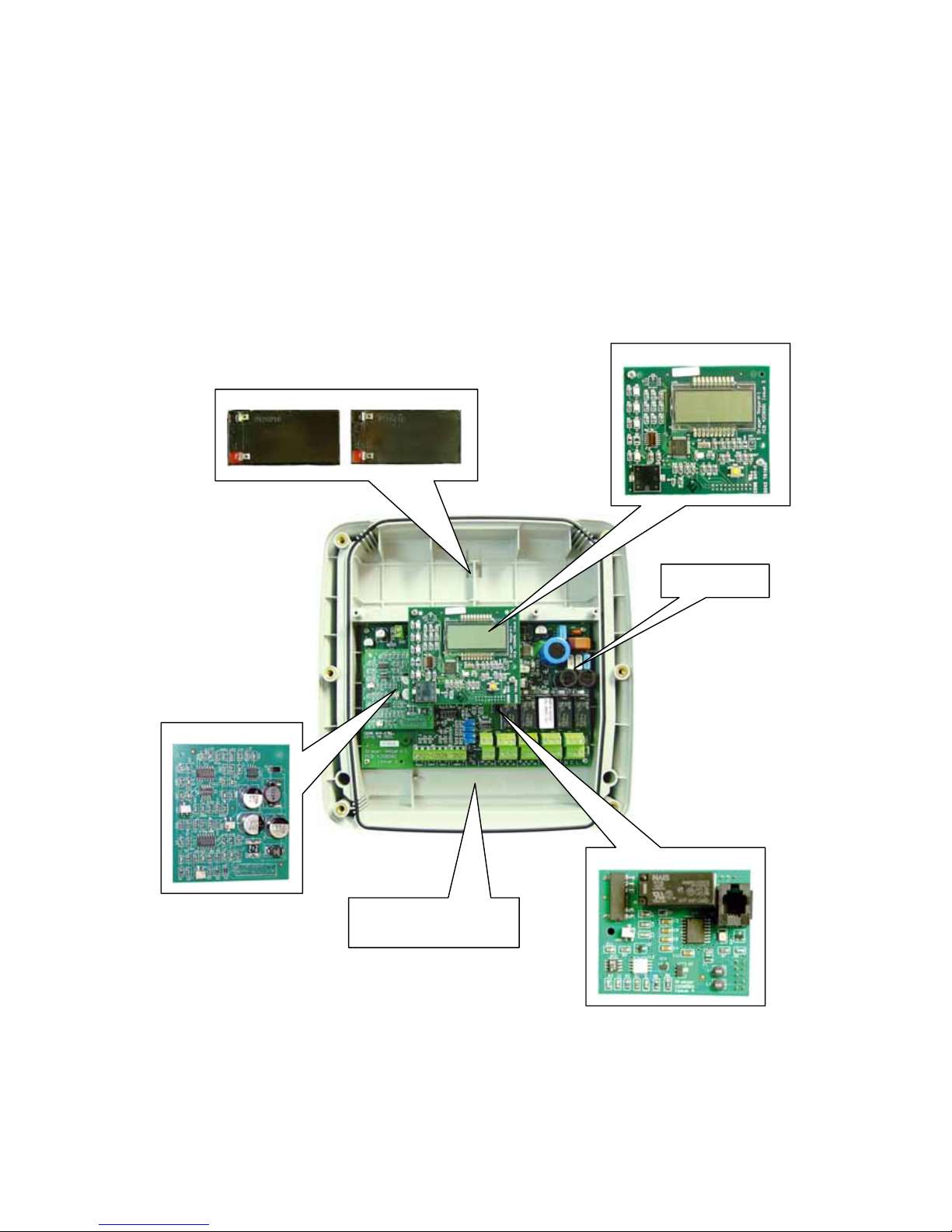
DESCRIPTION
The unit is available in two versions: 4-20mA or SE Ex, with or without gas level
display.
An additional “Options board” is available that provides an isolated 4-20mA output,
TWA alarm relay and data logger with RS-232.
Two 1.2AH lead-acid batteries can be fitted inside the unit’s enclosure to provide
continued operation for several hours if AC power is interrupted.
Lead-acid batteries
Display board
Pellistor board
Options board
Main board
Cable entry area
Issue 6 – December 2006
7
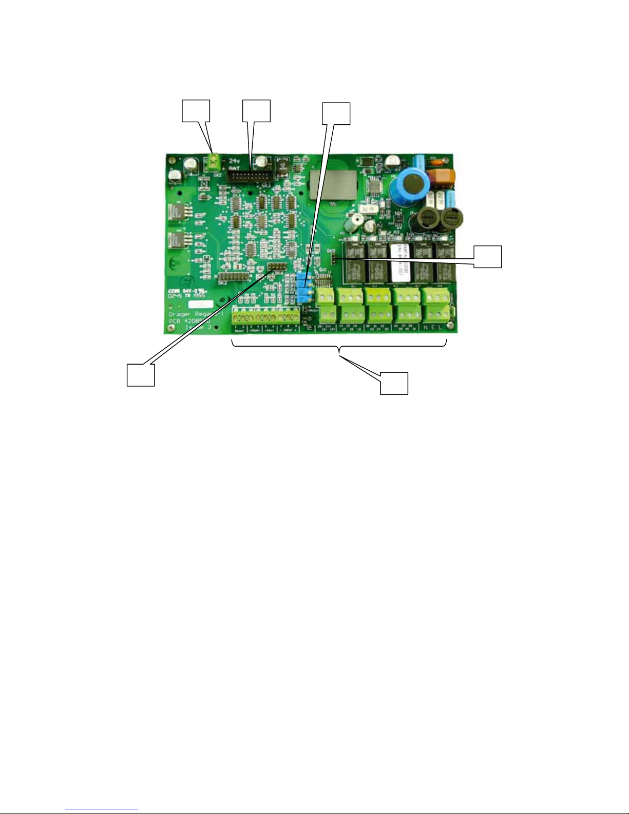
Main board
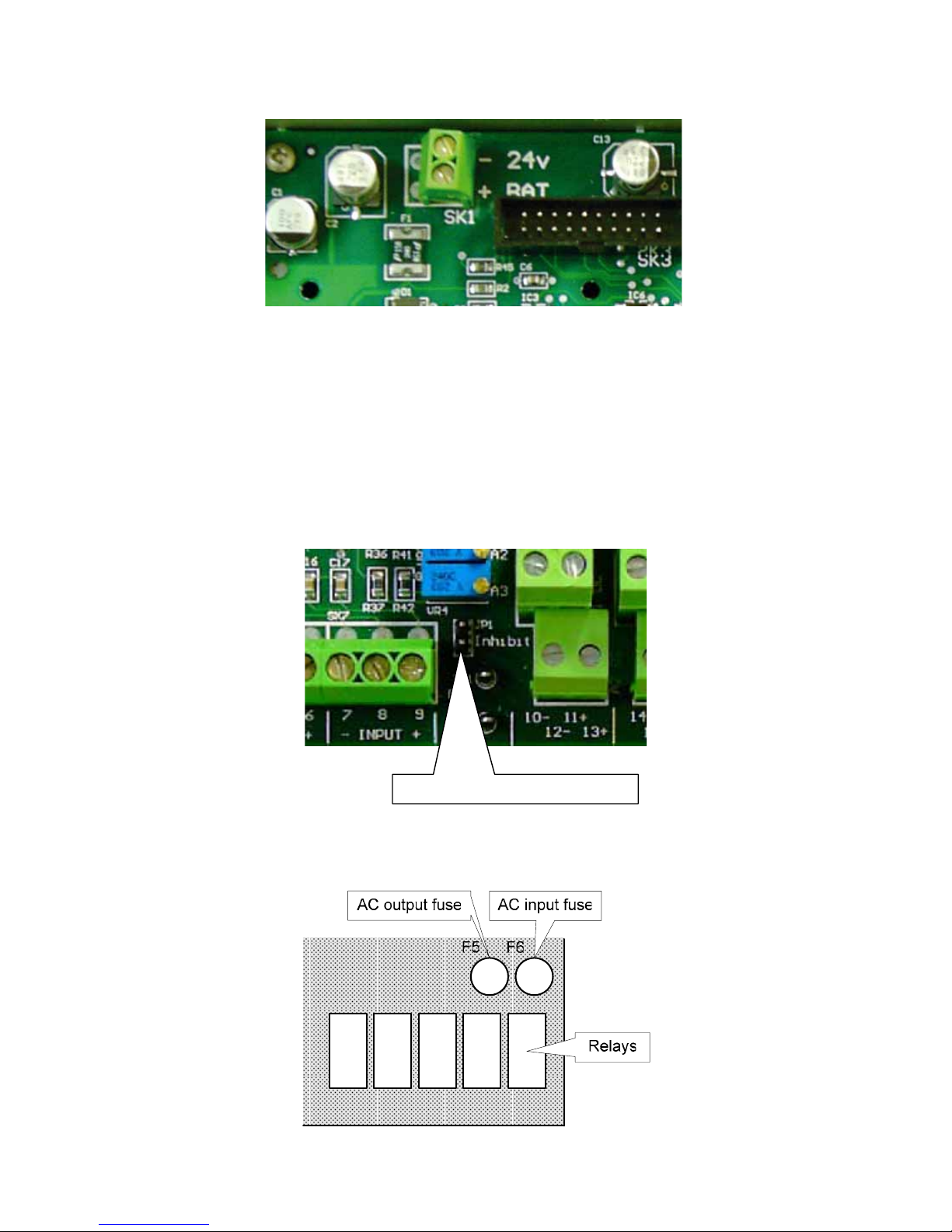
1. Terminals for batteries or external DC input.
2. Connector for display board.
3. Potentiometers for A1 – A3 alarms and display adjustment.
4. Terminals for field devices.
5. Connector for Options board.
1 2
3
4
5
5
Issue 6 – December 2006
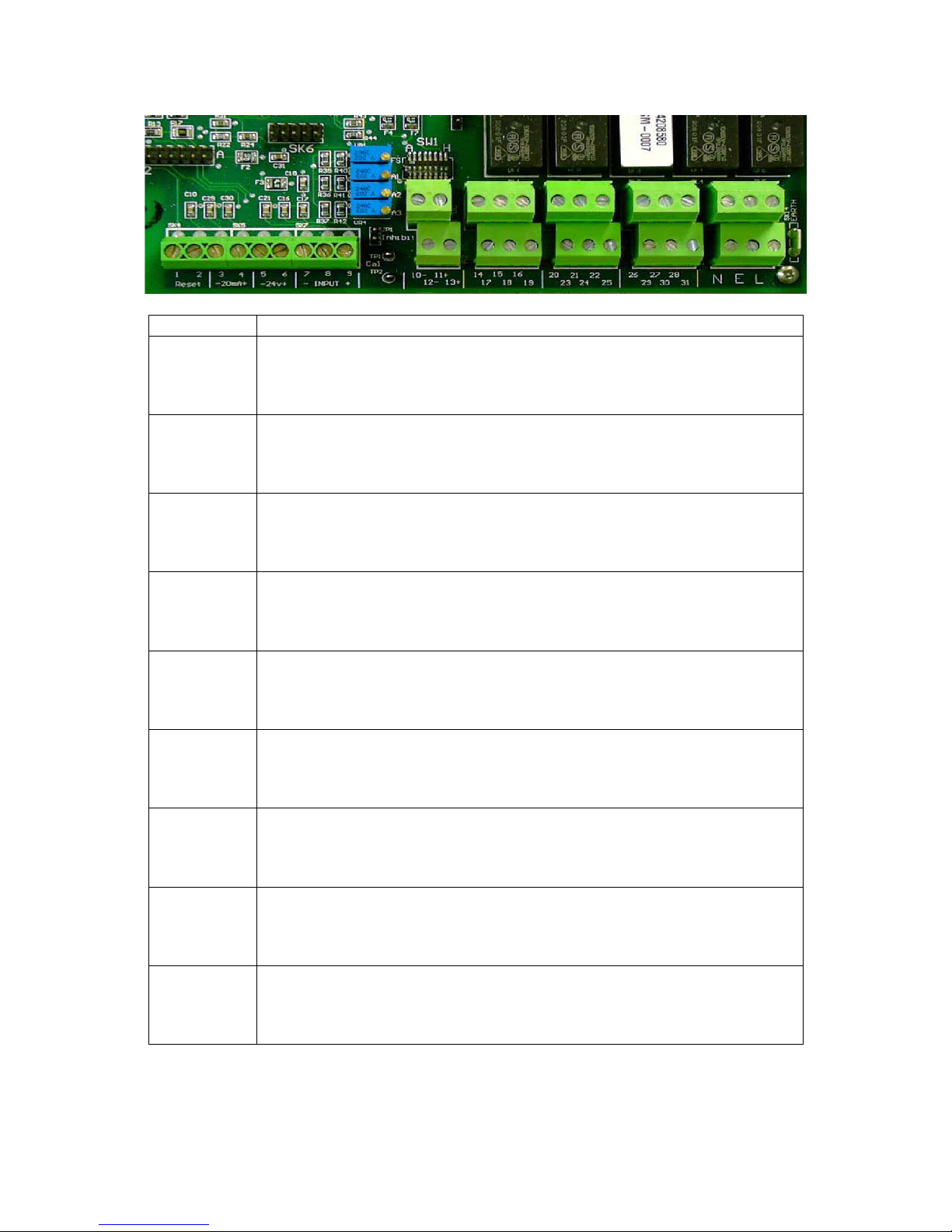
8
Field devices terminals
No Function
1 2
Reset
External reset input
3 4
- 20mA +
4-20mA output (requires Options board)
5 6
- 24V +
24 VDC unswitched output (100mA max.)
7 8 9
- Input +
4-20mA transmitter or SE Ex sensor input
10- 11+
12- 13+
A1 24V switched output (100mA max.)
A2 24V switched output (100mA max.)
14 15 16
17 18 19
A1 relay output
A2 relay output
20 21 22
23 24 25
TWA relay output (requires Options board)
A3 relay output
26 27 28
29 30 31
Fault relay output
Inhibit relay output
N E L
98 – 253 VAC fused output (500mA max.) (back row terminals)
98 – 253 VAC input (front row terminals)
Issue 6 – December 2006
9
24 V battery terminals
For continued operation of the controller when the AC supply fails connect two 12V
1.2AH lead-acid batteries in series to the battery terminals. If unsealed batteries are
fitted, that could generate hydrogen when charged, drill a vent hole in the top of the
enclosure.
The 24V battery terminals can also be used for an external 24VDC input. Do not
connect AC and external DC supplies at the same time.
Maintenance inhibit jumper
When the inhibit jumper is fitted all relays will go to their normal, non-alarm, state.
Fuses
Maintenance inhibit jumpe
r

Issue 6 – December 2006
10
0.50
- 0.5
-Ur-
-Or-
Display board
The display shows the gas level, or indicates that the gas level exceeds the
measuring range (over-range) or is below the measuring range (under-range).
Examples
Normal gas level display.
Negative display reading. A negative display reading
may be caused by inaccurate calibration or by drift or
temperature effect of the sensor.
Under-range: reading below measuring range
Over-range: reading above measuring range. The
over-range indication is latching and can only be
cleared when the reading is again within the
measuring range. Press Reset to clear the overrange indication.
There are two versions of the display board:
x V1 displays gas level, under-range and over-range, and calculates a TWA gas
level over eight hours; this board contains firmware release 1.00 or 1.01.
x V2 displays gas level, under-range and over-range and calculates the TWA
gas level over an user-adjustable period, and logs the gas level to memory;
this board contains firmware release 2.00 or 2.01.
The firmware version is shown on the display for a few seconds after the unit is
turned on, and is also marked on the display board.
A buzzer on the display board provides a local audible alarm.
Display of measuring range, gas and unit
The front cover of the controller has a window in which to display the measured gas,
range and unit. Insert a label showing the required information in the slot inside of the
front cover. Pre-printed and blank labels are at the end of this manual.
Issue 6 – December 2006
11
Pellistor board
The pellistor board supplies a constant current to the sensor and amplifies the signal
from the sensor.
To fit the pellistor board to a Regard-1 4-20:
x Remove all the links from SK2 on the main board
x Fit the pellistor board onto SK2
The pellistor board has a 4-pole switch and three potentiometers:
x SW1
Sets sensor current range and amplifier range
x VR1
Sets zero point
x VR2
Sets sensor current
x VR3
Sets gain (span)
Options board
The option board provides
x TWA alarm relay (requires display board V2 to operate)
x 4-20mA output proportional to gas level
x datalogger output
Fit the options board onto SK6 and SK9 on the main board.
SW1
VR3
VR1
VR2
Issue 6 – December 2006
12
When the Options board is fitted, the 4-20mA output is on terminals 3 and 4 of the
main board and the TWA relay output is on terminals 20 to 22.
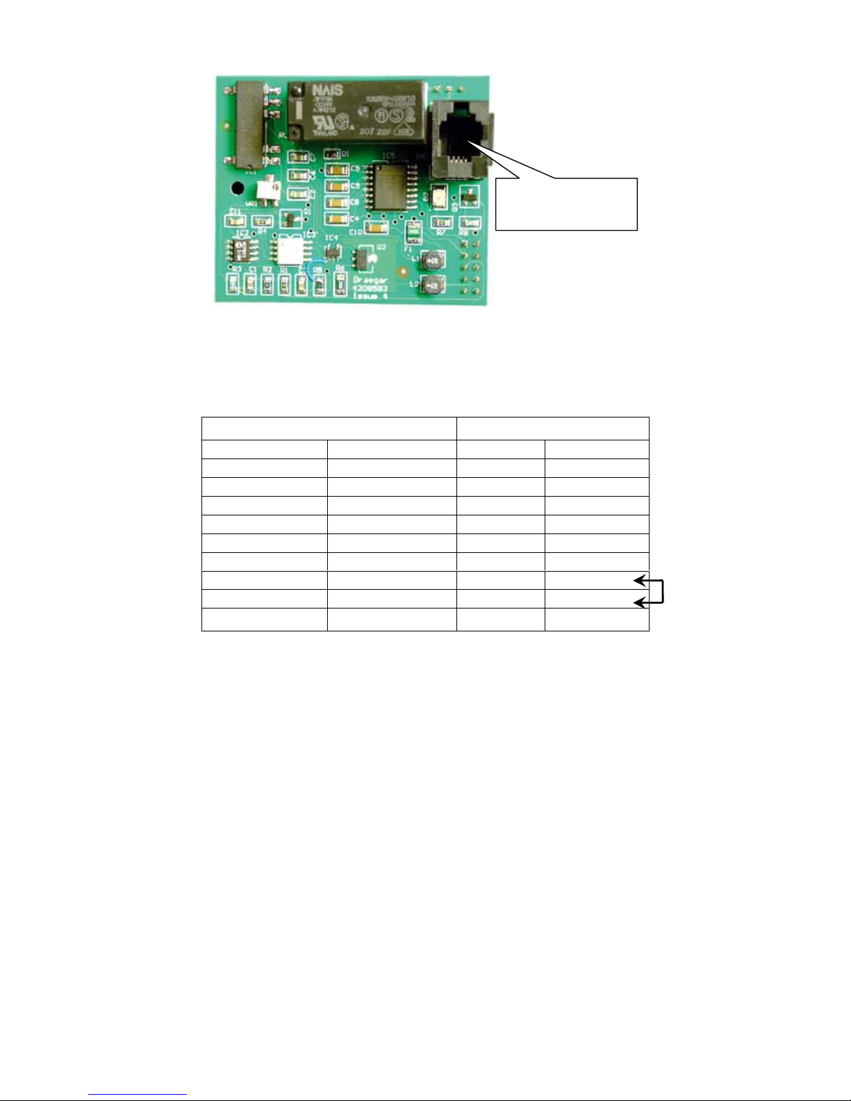
The RS-232 datalogger output is on an RJ11-style 4-position/4-conductor socket.
Data are sent by the controller as ASCII characters
Data rate: 2400 Baud
Data bits: 8
Stop bits: 1
Parity: none
Protocol: Xon / Xoff
The gas level is and TWA are printed every 1s. For example:
Gas 20.1 TWA 0.1
To reset the TWA value to zero, hold the unit’s Reset pushbutton pressed for 10s, or
hold the remote reset input closed for 10s, until the display shows tA-0.
RJ11 socket RS 232 Sub D – 9 Pole
Pin Function Pins Function
1 Rx 3 Tx
2 0 V 5 GND
3 Tx 2 Rx
4 0 V 5 GND
1 nc
6 nc
7 RTS
8 CTS
9 nc
RS-232 data
logger output

Issue 6 – December 2006
13
INSTALLATION
Installation environment
When selecting the installation place, consider the following::
x Locate the unit where the display and indicators are easily seen, and controls
are accessible
x The equipment is not “explosion proof” and must not be installed in a
hazardous area without additional Ex-protection.
x Avoid locations where excessive vibration is possible
x Avoid locations where aggressive or corrosive gases, contaminants or
pollutants harmful to electronic equipment, are present
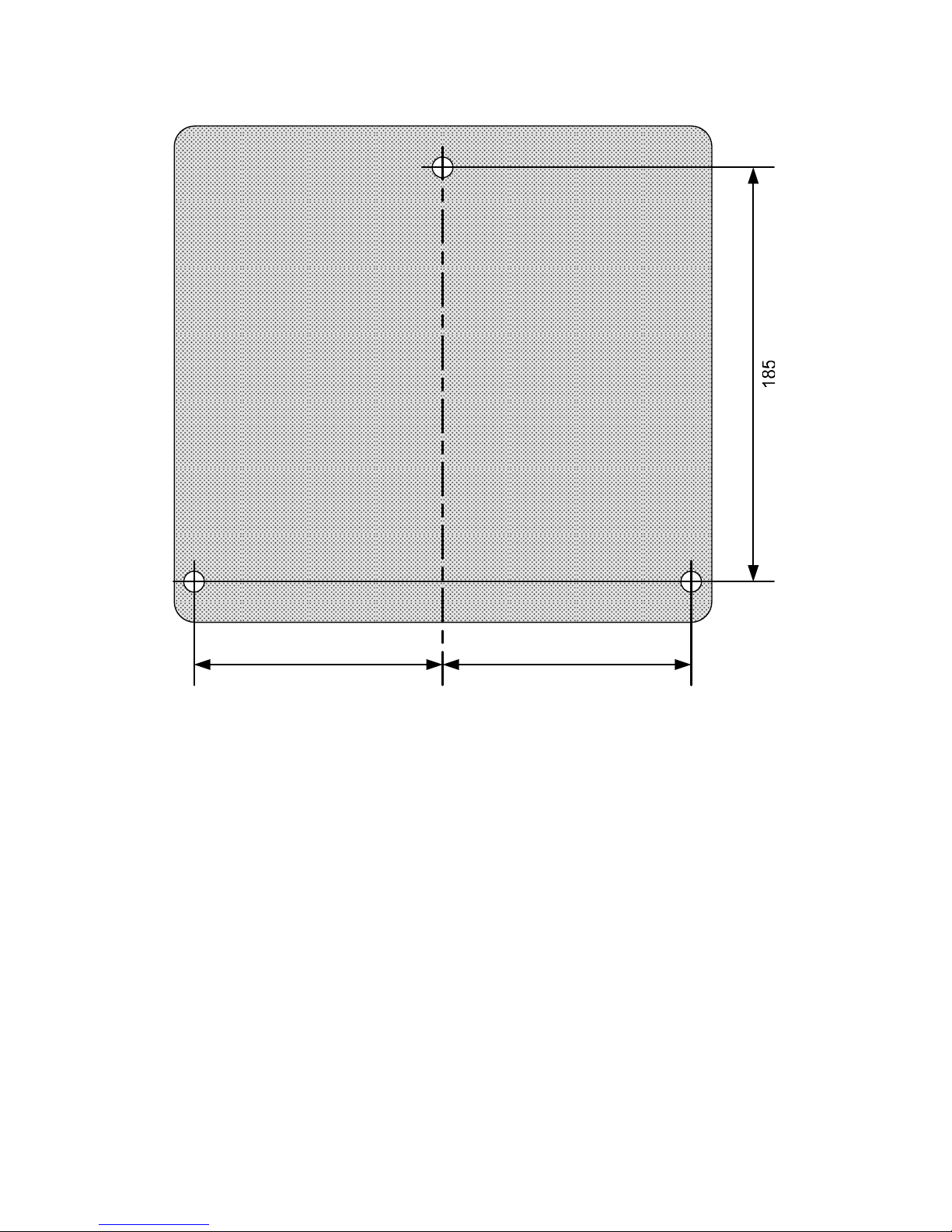
Mounting points
Mounting points of the enclosure base are shown here:
Mounting point
Mounting
hole
Mounting
hole
Mounting
hole
Mounting
hole
Front view Back view
Issue 6 – December 2006
14
Mounting points dimensions (not to scale):
114 114
Use a hole cutter to make the cable entries. Do not attempt to “knock out” the
cable entries.
AC supply
Connect a permanent AC supply to the unit.
If the AC supply to the unit is from an AC socket, the maximum allowed length of
cable between the socket and the unit is 3m.
Issue 6 – December 2006
15
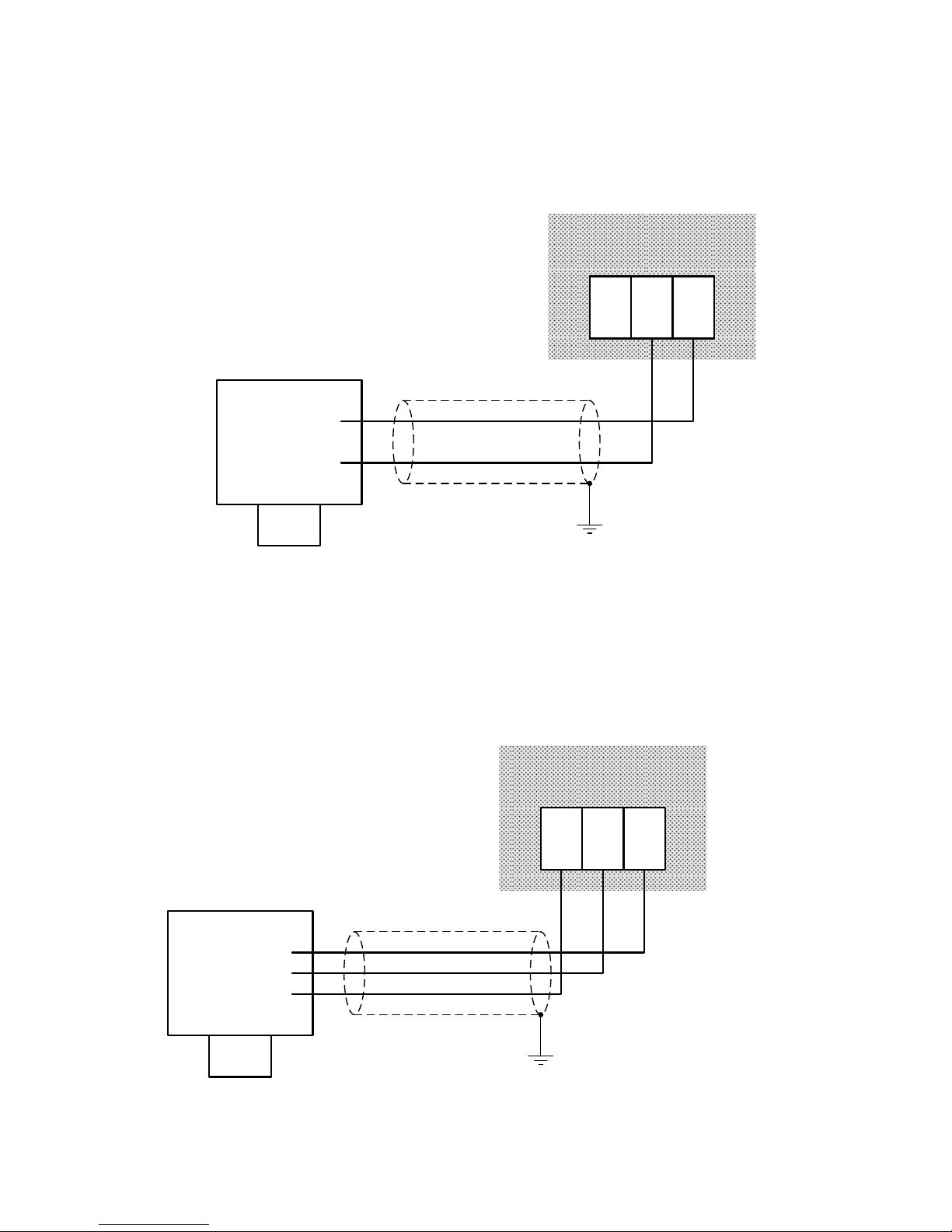
Connecting transmitters and measuring heads
Two-wire 4-20mA transmitter
Use cable with braided copper screen.
7 8 9
4-20mA signal
+ 24V
4-20mA transmitter
Regard-1 main board
Three-wire 4-20mA transmitter
Only for a transmitter with 4-20mA source output. Regard-1 will not work with a threewire transmitter that has a 4-20mA sink output.
Use cable with braided copper screen.
7 8 9
0V
4-20mA signal
+ 24V
4-20mA transmitter
Regard-1 main board

Issue 6 – December 2006
16
Maximum cable resistance for three-wire transmitters
When using 3-wire transmitters, to ensure that a short circuit between the 4-20mA
output and the zero volt wire at the transmitter causes a fault indication at the
controller, the cable resistance must not exceed the value given by the following
formula:
txr
cable
I
800
R
where:
Rcable is the resistance per core from Regard-1 to the transmitter,
Itxr is the transmitter operating current (in mA)
This formula assumes that the three cores of the connecting cable each have the
same resistance.
Example Polytron IR operating current at 24V is approx. 200mA. So limit of cable
resistance is
core per ohms 4
200
800
Two-wire 4-20mA transmitter with safety barrier
The following diagram shows the general arrangement. Refer to specific instructions
for safety barrier and transmitter for connections between transmitter and barrier, and
for instruction for earthing of barrier, where necessary.
Use cable with braided copper screen.

Issue 6 – December 2006
17
Polytron SE Ex (Pellistor) measuring head
Use cable with braided copper screen.
Do not connect the sensor/measuring head when the controller is powered:
this will damage the sensor.
Maximum cable resistance
The maximum allowed cable resistance is 6 ohms per core with the Dräger SE Ex
sensor. This limits the cable length according to the cross-sectional area of the cable:
Cable x-section Maximum length
1.0 mm2 250 m
1.5 mm2 400 m
2.5 mm2 700 m
4.0 mm2 1000 m

Issue 6 – December 2006
18
Relay outputs
Relay contacts when relays are in their normal state (ie, no alarm):
A1 relay
A2 relay
TWA relay
A3 relay
Fault relay
Inhibit relay
The fault relay is energised in its normal state (ie, when there is no fault)
Unscreened cable can be used for relay outputs.
A1 and A2 24V “digital” outputs
The digital outputs can be used to drive alarm devices directly. Use cable with
braided copper screen.
Example: flashing beacon activated by A1 alarm and klaxon activated by A2 alarm:

Issue 6 – December 2006
19
Output voltage and current
The voltage at each output decreases as the current drawn from the output
increases.
Output
voltage
Current
available
22 V 30 mA
18 V 100 mA

Issue 6 – December 2006
20
Remote reset input
To acknowledge and reset alarms remotely from the controller, connect a normallyopen switch to the remote reset terminals. Close the contacts momentarily to
acknowledge / reset alarm(s).
Use cable with braided copper screen.

Issue 6 – December 2006
21
CONFIGURATION AND CALIBRATION
Set measuring range
Use switch SW1 on the display board to set the display measuring range.
The number of decimal places is fixed according to the measuring range.
For display board with r1.00 or r2.00 firmware*, set the range using this table:
SW1
Measuring
range
DPs
A B C D E
0 - 1 2 OFF OFF OFF OFF OFF
0 - 3 2 ON OFF OFF OFF OFF
0 - 5 2 OFF ON OFF OFF OFF
0 - 10 2 ON ON OFF OFF OFF
0 - 25 1 OFF OFF ON OFF OFF
0 - 30 1 ON OFF ON OFF OFF
0 - 50 1 OFF ON ON OFF OFF
0 - 100 1 ON ON ON OFF OFF
0 - 200 0 OFF OFF OFF ON OFF
0 - 250 0 ON OFF OFF ON OFF
0 - 300 0 OFF ON OFF ON OFF
0 - 500 0 ON ON OFF ON OFF
0 - 1000 0 OFF OFF ON ON OFF
0 - 2000 0 ON OFF ON ON OFF
0 - 2500 0 OFF ON ON ON OFF
0 - 3000 0 ON ON ON ON OFF
0 - 5000 0 OFF OFF OFF OFF ON
0 - 9999 0 ON OFF OFF OFF ON
DPs = decimal places
SW1

Issue 6 – December 2006
22
* The firmware version is shown on the display for a few seconds after the unit is
turned on.
For display board with r1.01 or r2.01 firmware, set the range using this table:
SW1
Measuring
range
DPs
A B C D E
0 - 1 2 OFF OFF OFF OFF OFF
0 - 3 2 ON OFF OFF OFF OFF
0 - 5 2 OFF ON OFF OFF OFF
0 - 8 2 ON ON OFF OFF OFF
0 - 10 2 OFF OFF ON OFF OFF
0 - 20 1 ON OFF ON OFF OFF
0 - 25 1 OFF ON ON OFF OFF
0 - 30 1 ON ON ON OFF OFF
0 - 50 1 OFF OFF OFF ON OFF
0 - 100 1 ON OFF OFF ON OFF
0 - 200 0 OFF ON OFF ON OFF
0 - 250 0 ON ON OFF ON OFF
0 - 300 0 OFF OFF ON ON OFF
0 - 500 0 ON OFF ON ON OFF
0 - 1000 0 OFF ON ON ON OFF
0 - 2000 0 ON ON ON ON OFF
0 - 2500 0 OFF OFF OFF OFF ON
0 - 3000 0 ON OFF OFF OFF ON
0 - 5000 0 OFF ON OFF OFF ON
0 - 9999 0 ON ON OFF OFF ON
DPs = decimal places
For all firmware versions SW1-F sets the TWA function:
SW1-F TWA
ON ON
OFF OFF
Insert a card in the window above the display to show the measured gas and range.
Pre-printed and blank labels are at the end of this manual.

Issue 6 – December 2006
23
Calibrating a 4-20 unit
(Also refer to the transmitter’s operating manual for calibration instructions.)
Zero calibration
There is no zero adjustment for the 4-20 unit. The controller will indicate zero for a
transmitter signal of 4mA ± 0.3mA. If necessary, calibrate the transmitter to give
4.0mA at zero gas.
Span calibration
Span calibration can be performed either by applying calibration gas to the
transmitter/sensor, or by controlling the output of the transmitter directly (eg, by
means of the transmitter’s front panel controls) to simulate a gas signal.
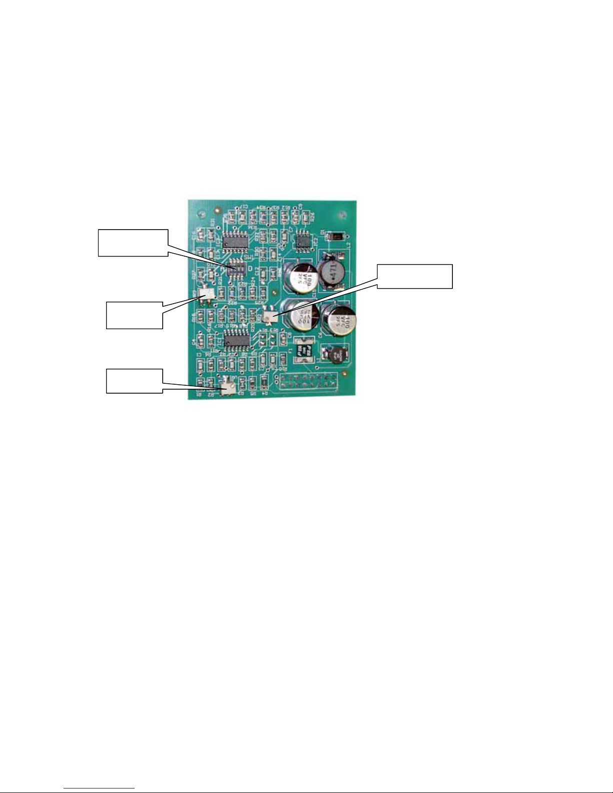
x Connect a voltmeter across TP1 and TP2 on the main board:
If applying calibration gas to the transmitter:
x Apply calibration gas to the transmitter. Use a gas concentration that is between
40% and 90% of measuring range.
x Adjust potentiometer FS on the main board until the voltage across TP1 and TP2
corresponds to the gas concentration. If the controller has a display, confirm that
the reading is correct.
Gas concentration
(as % of measuring range)
Voltage across
TP1 & TP2 (V)
40 2.08
50 2.40
60 2.72
70 3.04
80 3.36
90 3.68

Issue 6 – December 2006
24
Location of FS (span adjust) potentiometer:
If controlling the transmitter output:
x Adjust the output of the transmitter to 20mA if possible; otherwise to a value
between 12mA and 20mA.
x Adjust potentiometer FS on the main board until the voltage across TP1 and TP2
corresponds to the transmitter output. If the controller has a display, confirm that
the reading is correct.
Transmitter output (mA) Voltage across
TP1 & TP2 (V)
Display reading
(0 – 100 range*)
12 2.4 50
13 2.6 56
14 2.8 63
15 3.0 69
16 3.2 75
17 3.4 81
18 3.6 88
19 3.8 94
20 4.0 100
* Scale for different measuring range
FS: span adjust

Issue 6 – December 2006
25
Calibrating an SE Ex unit
Use the controls on the pellistor board to set sensor current, calibrate zero and
calibrate span:
(Also refer to the measuring head’s operating manual for calibration instructions.)
Set the sensor current
1. Set the sensor drive current range with SW1-A on the pellistor board.
For all Dräger sensors, set SW1-A to OFF.
SW1
Drive current
range
A B C D
95 – 195 mA ON – – –
190 – 350 mA OFF – – –
The position of switches B, C and D does not matter yet.
2. Adjust the sensor current to the required value
x Turn off the unit by disconnecting the AC or DC supply and batteries, if fitted
x Connect an ammeter between terminal 9 and the sensor
x Re-connect the AC or DC supply
x Adjust VR2 on the pellistor board to set the current (270.0 mA for Dräger Ex
sensors). Allow two minutes for the current to settle after adjusting VR2. Readjust VR2 if necessary
x Disconnect power, remove the ammeter and reconnect the sensor
x Turn on power and allow sensor to settle or at least five minutes before
continuing with zero and calibration
SW1
VR3
VR1
VR2

Issue 6 – December 2006
26
Do not connect the sensor/measuring head when the controller is powered:
this will damage the sensor.
Calibrate zero
x Connect a voltmeter across TP1 and TP2 on the main board:
x Apply known clean air – free of flammable gas – or verify that no flammable
gas is present at the sensor.
x Turn VR1 on the pellistor board until the voltage across TP1 and TP2 is
800mV ± 20 mV. To increase the reading, turn VR1 anti-clockwise
.
x If the controller has a display, verify that it reads zero.
Calibrate span
1. Set sensitivity range
Set the amplifier gain range using switches SW1-B, -C and -D.
Range SW1
No. Sensitivity A B C D
1
10 – 60 mV
x
ON OFF OFF
2
60 – 110 mV
x
OFF ON OFF
3
110 – 160 mV
x
OFF OFF ON
4
160 – 220 mV
x
OFF OFF OFF
x Do not change the position of switch SW1-A.
For new Dräger Ex sensors, range 3 (110 – 160 mV) should work for most gases. If,
during calibration, the gas reading does not reach the required value use a lowernumbered sensitivity range. If the display reading is too high use a higher-numbered
sensitivity range.

Issue 6 – December 2006
27
2. Apply calibration gas
Use a calibration gas with concentration between 40% and 60% of the measuring
range.
x Apply gas using calibration adaptor at 0.5 l/min flow rate.
x Allow display reading to settle (about 2 to 3 minutes)
x Adjust VR3 on the pellistor board until the voltage across TP1 and TP2
corresponds to the concentration of the calibration gas.
Gas concentration
(as % of measuring range)
Voltage across
TP1 & TP2 (V)
40 2.08
45 2.24
50 2.40
55 2.56
60 2.72
x If the unit has a display, verify that the display reading corresponds to the gas
concentration.

Issue 6 – December 2006
28
Configuring alarms
There are three gas alarms. Each alarm can be set to be
x rising or falling
x latching or non-latching
Note
Regard-1 4-20: if used with a transmitter whose output current can be below 20mA
for concentrations above full scale, set the alarm relays latching.
Regard-1 SE
Ex: set at least one alarm relay – the one with the highest alarm level –
to be latching.
The A2 alarm can also be set to be acknowledgeable. You can use the A2 relay to
control an audible alarm that you want to be able to silence even when the gas alarm
is still tripped.
Use switch SW1 on the main board set the operation of the alarms/relays:
A1 alarm
SW1
Mode of operation
A B
Rising
Falling
ON
OFF
Non-latching
Latching
ON
OFF
SW1 on main
board

Issue 6 – December 2006
29
A2 alarm
SW1
Mode of operation
C D H
Rising
Falling
ON
OFF
Non-latching
Latching
ON
OFF
Not acknowledgeable
Acknowledgeable
ON
OFF
A3 alarm
SW1
Mode of operation
E F
Rising
Falling
ON
OFF
Non-latching
Latching
ON
OFF
Fault alarm
SW1
Mode of operation
G
Non-latching
Latching
ON
OFF
x The A1, A2 and A3 relays energise on alarm.
x The Fault relay de-energises on alarm (ie, is normally energised).

Issue 6 – December 2006
30
Setting alarm thresholds on 4-20 units
Use the potentiometers marked A1, A2 and A3 on the main board to set the alarm
thresholds:
For safety relevant decisions only use status of Alarm/Fault LEDs and relays.
Do not use display reading. For calibration and adjustment of alarm set points
use DVM between test points TP1 and TP2 only.
To set the alarm levels you must simulate a gas signal. You can do this
x using a potentiometer that can be varied from 1200 to 6000 ohms
x by directly controlling the output of the transmitter
x using a 4-20mA loop calibrator
Using a potentiometer:
x Connect the potentiometer between terminals 8 and 9.
Test potentiometer
1200 to 6000 ohms
Test points
TP1 + TP2
A1 pot.
A2 pot.
A3 pot.

Issue 6 – December 2006
31
Using a 4-20mA source loop calibrator
x Connect the loop calibrator between terminals 7 and 8.
The method to set the alarm thresholds is the same for each.
To set A1 alarm
1. Turn A1 potentiometer fully clockwise
2. Adjust test pot until voltage across TP1 and TP2 is at the required threshold
3. Turn A1 pot anticlockwise until the A1 alarm trips
For the A2 and A3 alarms, repeat the above procedure with the A2 and A3
potentiometers.
x If an alarm is not required, turn its potentiometer fully clockwise.
x The fault alarm threshold is fixed at 3.2mA.
Use this table to determine the alarm threshold. Read off the voltage across TP1 and
TP2 corresponding to the required alarm threshold.
Alarm threshold
(% of 0 – 100 range)
Voltage across
TP1 & TP2 (V)
5% 0.96
10% 1.12
15% 1.28
20% 1.44
25% 1.60
30% 1.76
35% 1.92
40% 2.08
45% 2.24
50% 2.40
55% 2.56
60% 2.72
65% 2.88
70% 3.04
75% 3.20
80% 3.36
85% 3.52
90% 3.68
95% 3.84

Issue 6 – December 2006
32
For oxygen deficiency and enrichment alarms, use this table to determine alarm
thresholds for a 0 – 25% range:
Alarm threshold Transmitter signal
(mA)
Voltage across
TP1 & TP2 (V)
17% 14.9 2.98
18% 15.5 3.10
19% 16.2 3.24
20% 16.8 3.36
21% (Normal reading)
22% 18.1 3.62
23% 18.7 3.74
24% 19.4 3.88

Issue 6 – December 2006
33
Setting alarm thresholds on SE Ex units
Use the potentiometers marked A1, A2 and A3 on the main board to set the alarm
thresholds:
Use VR1 on the pellistor board
to simulate a sensor signal.
Measure the voltage across test points TP1 and TP2 to determine the alarm
threshold. If the unit has a display you can use the display reading to give additional
confirmation that the alarm set points are correct.
Alarm threshold
(% of 0 – 100
range)
Voltage across
TP1 & TP2 (V)
10% 1.12
15% 1.28
20% 1.44
25% 1.60
30% 1.76
VR1
A1
A2
A3

Issue 6 – December 2006
34
35% 1.92
40% 2.08
45% 2.24
50% 2.40
55% 2.56
60% 2.72
Alarms below 10% and above 60% of measuring range are not recommended for
flammable gas detection.
To set A1 alarm
1. Turn A1 potentiometer fully clockwise
2. Adjust VR1 until the voltage across TP1 and TP2 is at the required
threshold (turn VR1 anticlockwise to increase the voltage across TP1
and TP2)
3. Turn A1 potentiometer anticlockwise until the A1 alarm trips
To set A2 alarm
1. Turn A2 potentiometer fully clockwise
2. Adjust VR1 until voltage across TP1 and TP2 is at the required
threshold
3. Turn A2 potentiometer anticlockwise until the A2 alarm trips
To set A3 alarm
1. Turn A3 potentiometer fully clockwise
2. Adjust VR1 until voltage across TP1 and TP2 is at the required
threshold
3. Turn A3 potentiometer anticlockwise until the A3 alarm trips
If an alarm is not required turn that alarm’s potentiometer fully clockwise.
After setting the alarm thresholds, adjust VR1 so that the voltage across TP1 and
TP2 is 800 mV ± 20 mV.
Regard-1 SE Ex has a fixed fault alarm threshold at about –5% of the measuring
range.

Issue 6 – December 2006
35
MAINTENANCE
Check the unit for operation regularly. Service the controller every 12 months.
The transmitter or measuring head may require periodic recalibration. Refer to the
instruction manual for the transmitter or measuring head for guidance.
If batteries are fitted to the control unit then these batteries should be maintained in
accordance with the instructions of the battery manufacturer.
Observe EN 50073 and respective national regulations.
Fault finding
Fault Remedy
1 Control unit non operational Check input fuse (F6). Replace if necessary.
Check third party electrical supply.
2 Display blank Check cable connection between main circuit
board and display board.
Adjust contrast potentiometer on display
board.
3 Self test routine fails Replace display board
4 Under-range displayed Check transmitter connections.
Check and measure loop current.
4-20 units:
Ensure links fitted to positions A, B, C,
D and E of SK2 on main board
5 24 Vdc output too low Check loading is < 100mA
6 A1 or A2 24 Vdc output too
low
Check loading is < 100mA
Reduce load
7 AC output failed Check loading does not exceed 500mA
Replace fuse.
8 Incorrect measuring range Check setting of SW1 on display board
10 No TWA information Set SW1-F on the display board to ON
11 Water ingress Check sealing ring is in place
12 Display repeats power-on test
during normal operation
(1)
Replace display board
Note 1: Display board program execution is monitored by a watchdog. A watchdog
reset during normal operation will cause the display to repeat its power-on
self test.

Issue 6 – December 2006
36
SPECIFICATIONS
Regard-1 4-20 Regard-1 SE Ex
Dimensions
270 mm u 270 mm u 90 mm
Mass (without
batteries)
Approx. 2.5 kg
Housing material ABS – VO
Ingress protection IP 65
Cable entries 6 No. M20
AC supply voltage 98 to 253 VAC, 50-60 Hz
DC supply voltage 18 to 30 VDC
Power consumption 50 W (without transmitter) 70 W (including sensor)
Mains fuses 500mA (T) HRC.
Battery charge
voltage
- maximum current
27.6 r 0.6 VDC
500 mA
DC output
24 r 1 VDC, 100 mA max.
Battery type (x2) 12 V, 1.2 AH
A1 and A2 outputs
22 VDC at 30 mA
18 VDC at 100 mA
Alarm relays
(A1, A2, A3)
single-pole changeover
max. 250 VAC, 3 A
max. 30 VDC, 2 A
energise on alarm
Fault relay
single-pole changeover
max. 250 VAC, 3 A
max. 30 VDC, 2 A
normally energised (de-energise on fault)
Inhibit relay
single-pole changeover
max. 250 VAC, 3 A
max. 30 VDC, 2 A
energise on alarm
Visual outputs
- with display board
fitted
“AC power on” LED
“DC power on” LED
A1, A2 and A3 alarm LEDs, Fault LED, Inhibit LED
LCD gas level indicator
Transmitter/sensor
input
2- or 3-wire 4-20mA,
24 VDC / 400 mA
3-wire Pellistor
constant current supply
200…350 mA
Storage conditions
–10°C to 60°C
0 to 100% rH, non-condensing
Operating conditions
0°C to 55°C
0 to 100% rH, non-condensing
Warm up time 30 s
Response time
2 s
Approvals and CE Electromagnetic Compatibility (EMC) Directive

Issue 6 – December 2006
37
marking Low-voltage directive
ATEX directive
Data logger RS-232
output
Format: ASCII
Data rate: 2400 Baud
Data bits: 8
Stop bits: 1
Parity: none
Flow control: Xon / Xoff
Part numbers
Description Part number
Regard-1 4-20 4208585
Regard-1 SE Ex 4208600
Accessories and spare parts
Pellistor board 4208582
Options board 4208583
Lead-acid batteries (2 off) 4208586
Display board V1 4208581
Display board V2 4208636
Calibration screwdriver 4208595
PC connection lead 4208596
“Light pipes” 4208589

Issue 6 – December 2006
38
EC type-examination certificate

Issue 6 – December 2006
39

Issue 6 – December 2006
40

Issue 6 – December 2006
41

Issue 6 – December 2006
42
x Display board V2.0 is not included in the scope of this type-examination.
x The options board is not included in the scope of this type-examination.

Issue 6 – December 2006
43
EC Declaration of Conformity
DECLARATION OF CONFORMITY
We
Draeger Safety UK Ltd
Kitty Brewster Industrial Estate
Blyth, Northumberland
NE24 4RG
England
declare that
REGARD–1
in accordance with Directive 94/9/EC (Equipment and protective systems intended
for use in potentially explosive atmospheres), is in conformance with the EC-Type
Examination Certificate
BVS 03 ATEX G 011 X
for equipment group and category
II (2) G
issued by
EXAM BBG Prüf- und Zertifizier GmbH
Dinnendahlstrasse 9
44809 Bochum
Germany
Notified body number 0158.
Harmonized standards:
EN 61779-1:2000 + A11:2004
EN 61779-4:2000
EN 61779-5:2000
EN 50104:2002 + A1:2004
EN 50271:2001
(Signed) D Longstaff
____________________
Technical Manager
June 2005

Issue 6 – December 2006
44

Issue 6 – December 2006
45
Front panel labels
Gas A1:
Range A2:
Unit A3:
Gas Methane (CH4) A1: %LEL
Range 0 – 100 A2: %LEL
Unit %LEL A3: %LEL
Gas A1:
Range A2:
Unit A3:
Gas Oxygen (O2) A1: %vol rising / falling
Range 0 – 5 / 25 / 100 A2: %vol rising / falling
Unit %vol A3: %vol rising / falling
Gas Ammonia (NH3) A1: ppm
Range 0 – 100 / 300 / 1000 A2: ppm
Unit ppm A3: ppm
Gas Carbon monoxide (CO) A1: ppm
Range 0 – 100 / 300 / 1000 A2: ppm
Unit ppm A3: ppm
Gas Hydrogen sulphide (H2S) A1: ppm
Range 0 – 20 / 50 / 100 A2: ppm
Unit ppm A3: ppm

Issue 6 – December 2006
46

Issue 6 – December 2006
47

Issue 6 – December 2006
48
Draeger Safety UK Ltd
Kitty Brewster Industrial Estate
Blyth
Northumberland
NE24 4RG
United Kingdom
Tel +44 1670 352891
Fax +44 1670 544475
Manual part number 4208591
This manual supersedes and replaces the following manuals:
4208603 issue 1
4208591 issue 5
For use with display board firmware r1.00 and r1.01.
 Loading...