

Page 1
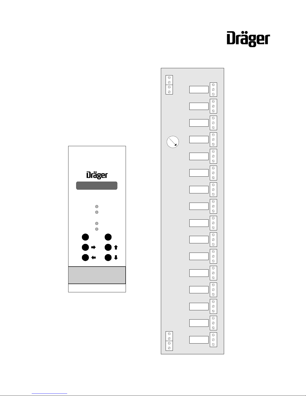
RELAY MODULE
RELAY DISPLAY CARD
(ATEX VERSION)
REGARD
GAS DETECTION SYSTEM
RELAY DISPLAY
Alarm
Tripped
Power
Inhibit
R
SHIFT
012:ALRM
INSTRUCTIONS FOR USE
Page 2

Page 3

REGARD Relay Module & Relay Display Card (ATEX version)
Issue 1 – July 2003
3
CONTENTS
Page
FOR YOUR SAFETY............................................................................................................... 4
Safe operation ................................................................................................................ 4
CE marking and ATEX marking...................................................................................... 5
Special conditions for safe use....................................................................................... 5
OPERATION............................................................................................................................ 6
Intended use................................................................................................................... 6
Description..................................................................................................................... 6
Operational fault relay .......................................................................................... 6
Electromagnetic compatibility......................................................................................... 6
Display card front panel controls and indicators.............................................................. 7
Display ................................................................................................................. 7
LEDs.................................................................................................................... 7
Controls................................................................................................................ 8
Relay module indicators................................................................................................. 8
Acknowledging alarms.................................................................................................... 8
Relays configured “Single” and “LNAK1” ............................................................... 9
Operational faults..........................................................................................................10
Operational fault codes........................................................................................10
WARNING - FAULT C indication on the relay display card..................................11
WARNING - FLTMB indication on the relay display card .....................................11
Loss of communication between relay display card and relay module(s)..............11
INSTALLATION ......................................................................................................................12
Install relay display card................................................................................................12
Install relay modules......................................................................................................12
Set module numbers ...........................................................................................15
Connect equipment to relay terminals..................................................................16
Connect DC supply to modules............................................................................16
Optional connections.....................................................................................................17
Remote reset.......................................................................................................17
Operational fault relay .........................................................................................17
Switch-on and initial checks...........................................................................................18
CONFIGURATION..................................................................................................................19
Command mode............................................................................................................19
Function of front panel controls in command mode..............................................19
Table of commands .............................................................................................20
Configure channel cards and master card......................................................................21
Configure relay display card..........................................................................................21
Configuration sequence.......................................................................................22
Optional configuration settings.............................................................................27
MAINTENANCE......................................................................................................................28
Recommended maintenance intervals...........................................................................28
Commands for system maintenance..............................................................................29
TECHNICAL DATA .................................................................................................................33
Relay display card.........................................................................................................33
Relay module................................................................................................................33
Part numbers.................................................................................................................33
EC-Type Examination certificate...................................................................................34
Page 4

REGARD Relay Module & Relay Display Card (ATEX version)
Issue 1 – July 2003
4
FOR YOUR SAFETY
Follow the instructions
Follow the instructions for installation, operation and maintenance.
Use in areas subject to explosion hazards
The relay module and relay display card are not designed for use in a flammable
atmosphere without suitable protection.
Liability for proper function or damage
Liability for proper function of this apparatus is irrevocably transferred to the owner or
operator to the extent that the apparatus has been commissioned, serviced or
repaired by personnel not employed or authorised by Draeger Service, or when this
apparatus was used in a manner not conforming to its intended use.
Draeger Limited can not be held responsible for any damage caused by noncompliance with the above recommendations. The warranty and liability provisions of
the terms and conditions of sale and delivery of Draeger Limited are likewise not
modified by recommendations given above.
Maintenance
This apparatus must be inspected and serviced by experts at regular intervals and a
record maintained of such inspections and servicing. Repairs and general overhaul of
this apparatus should only be carried out by competent personnel.
We recommend that either a training course or service contract is obtained from the
Draeger Service department and that all repairs are also carried out by them.
Safe operation
For safe operation:
• Set relays on relay modules normally energised. In the event of power loss,
communications failure or configuration data loss, the relays will de-energise.
• Connect an alarm device or other indicator to the operational fault relay on the
relay display card.
Page 5

REGARD Relay Module & Relay Display Card (ATEX version)
Issue 1 – July 2003
5
CE marking and ATEX marking
Regard cards and modules are CE marked to indicate conformity with the essential
requirements of the “ATEX” Directive 94/9/EC:
0518
The number after the CE mark is the number of the Notified Body involved the
production control phase.
The card also carries the following marking in accordance with the directive:
This marking means that the card is suitable for use in non-hazardous areas, in nonmining Category 2 applications for the detection of flammable gases.
THIS MARKING DOES NOT MEAN THAT THE CARD IS “EXPLOSION PROOF”.
Regard cards cannot be used in areas subject to explosion hazards
(“hazardous areas”) without suitable additional protection.
The certification code corresponds with the ATEX EC-type-examination certificate:
DMT 02 ATEX G 002 X
The year of construction of the card/module can be derived from the card's/module's
serial number.
Special conditions for safe use
• When relay display card(s) and relay module(s) are used, the fault relay of the
master card shall be configured as master fault.
• After configuration of the relay display card, check that the Regard channels used
are present within the system.
• The power supply of the relay modules shall be supervised by external means in
such a way that there is a signal if the supply voltage falls below the minimum
value.
• If safety-related alarms or fault signals are configured with relay display cards and
relay modules, two relays on separate relay modules shall be used in a redundant
arrangement. The relays shall have the same configuration and be wired in such
a way that the external device is activated if one of the two relays switches.
• Relays that are intended for safety-related purposes shall be configured as
latching and non-acknowledgeable during the alarm condition.
II (2) G
Page 6

REGARD Relay Module & Relay Display Card (ATEX version)
Issue 1 – July 2003
6
OPERATION
Intended use
The REGARD relay modules and relay display card provide:
• Additional common and voted alarm relays for a system comprising any
combination of channel cards.
• A1, A2, A3 and/or Fault relays for each channel of a Regard HART card or eightchannel display card.
NOTE Neither A3 alarms nor use with the Regard 'HART' card are included in the
scope of the EC-type examination certificate DMT 02 ATEX G 002 X.
• Additional alarm relays for single-channel Regard cards.
The relay modules and relay display card are intended for permanent installation in a
non-hazardous environment, such as a control room or marshalling cabinet.
Description
The relay display card fits into the Regard rack and controls up to 16 relay modules.
Each relay module has 16 relays. The relay modules are connected to the relay
display card by a single twisted-pair cable. Relay modules can be located up to 1km
from the relay display card, allowing shorter cable runs between the actuating relays
and the controlled devices.
Up to eight relay display cards can be fitted in a Regard system – i.e. connected to
the same RS-485 bus. This restriction is removed if remote configuration of the relay
display cards is not required.
The relay display card “listens” to the messages on the RS-485 bus between the
Regard master card and channel cards. The relay display card requires a Regard
master card for operation. The master card must be configured to communicate
with all channel cards that are programmed on the relay display card .
NOTE – the relay display card gives no indication that a particular channel is not
communicating with the master card. Communication faults are indicated on either
the master card or the relevant channel card.
Operational fault relay
The relay display card has one relay, that indicates a critical operational fault of the
relay display card or relay module(s). This relay is always normally energised,
latching and non-acknowledgeable.
Electromagnetic compatibility
The Regard relay module and relay display card have been tested for compliance
with the EMC Directive. Take the following steps to ensure compliance:
• Installation must follow the instructions given in this manual.
• Installation must also follow the Draeger document “Guidelines for the construction
and installation of Regard systems to comply with the EMC Directive” which is
available separately.
• Observe instructions to use screened cable, where given
Instructions or precautions that are essential for electromagnetic compatibility are
identified by “EMC!” in the margin.
Page 7
REGARD Relay Module & Relay Display Card (ATEX version)
Issue 1 – July 2003
7
Display card front panel controls and indicators
Display
Display normally shows the state of each alarm relay in sequence. When a relay is in
its alarm state, only relays in alarm are displayed.
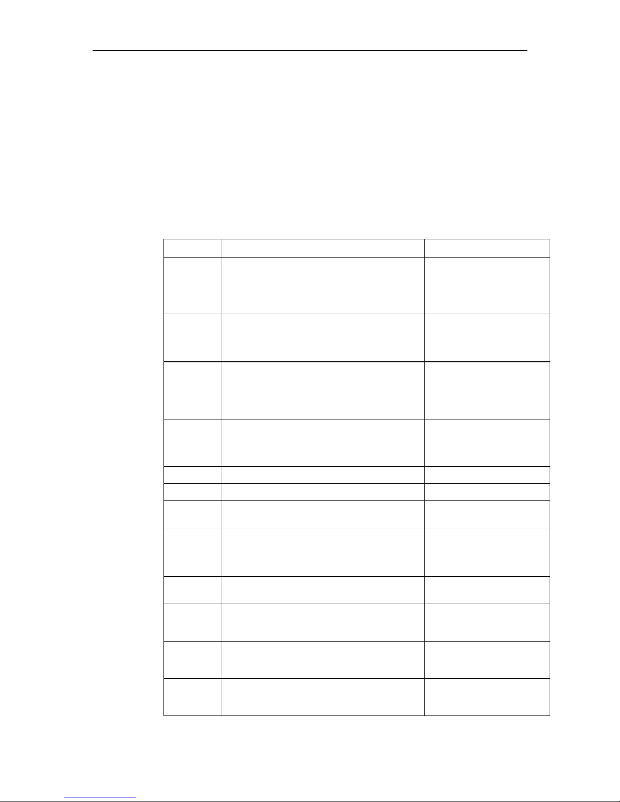
Display Meaning
001:CLR
Relay 001 in non-alarm state
002:ALRM
Relay 002 in alarm state
016:NOP
Operation of relay 016 not set (no operation)
256:DBLD
Relay 256 disabled
FAULT…
FLTM…
Operational fault
Relays are numbered from 001 to 256. Relays on relay module 1 are numbers 001 to
016, relays on relay module 2 are numbers 017 to 032, and so on.
LEDs
The LEDs show the status of the alarm relay currently featured in the display.
LED State Meaning
Alarm
On
Off
Relay in alarm state
Relay not in alarm state
Tripped
On
Flashing
Off
Alarm tripped & acknowledged
Alarm tripped, not acknowledged
No alarm
Power
On
Flashing
DC power on
Operational fault
Inhibit
On
Blinking on (normally
off, on every 5 secs)
Blinking off (normally
on, off every 5 secs.)
Relays inhibited
Relay(s) disabled
Relays inhibited + relays disabled
Page 8
REGARD Relay Module & Relay Display Card (ATEX version)
Issue 1 – July 2003
8
Controls
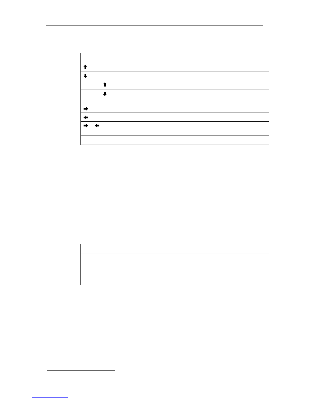
Function of front panel controls during normal operation:
Push button Result Note
Display relay latch mode
E.g. 001:LACK
Display relay energise mode
E.g. 023:ENER
SHIFT +
Display relay operating mode
E.g. 002:SA1
SHIFT +
Channel number of relay
configured SINGLE
E.g. 002:CH13
Display status of next relay —
Display status of previous relay —
+
Hold / release display of relay
status
Key presses alternately hold and
release display
R
Acknowledge / reset alarm —
Relay module indicators
• Power LED indicates that DC supply to module is connected.
• Relay LED next to each relay is lit when relay coil is energised.
Acknowledging alarms
The action required to acknowledge an alarm depends on it mode.
Momentarily connecting the remote reset terminals of the relay display card will also
acknowledge an alarm.
Note that, since one display card can control up to 256 relays, it is possible for all 256
relays to be acknowledged by a single reset operation. In particular, if any relays are
set to ACK1 or LACK1 then those relays will be untripped even in the presence of an
alarm condition (see the warning below).
Mode Action required to acknowledge alarm:
Common Press Reset on relay display card or master card
Single Automatically acknowledged by channel alarm (except when set
LNAK1)
Voted Press Reset on relay display card or master card
WARNING – when a relay latch mode is set to ACK1 or LACK1, a tripped relay
can be cleared even though an alarm condition may still be present. These
latch modes are generally employed as a convenience to silence audible alarms
while the cause of the alarm is being addressed.
1
See explanation of relay configuration options on page 25
Page 9
REGARD Relay Module & Relay Display Card (ATEX version)
Issue 1 – July 2003
9
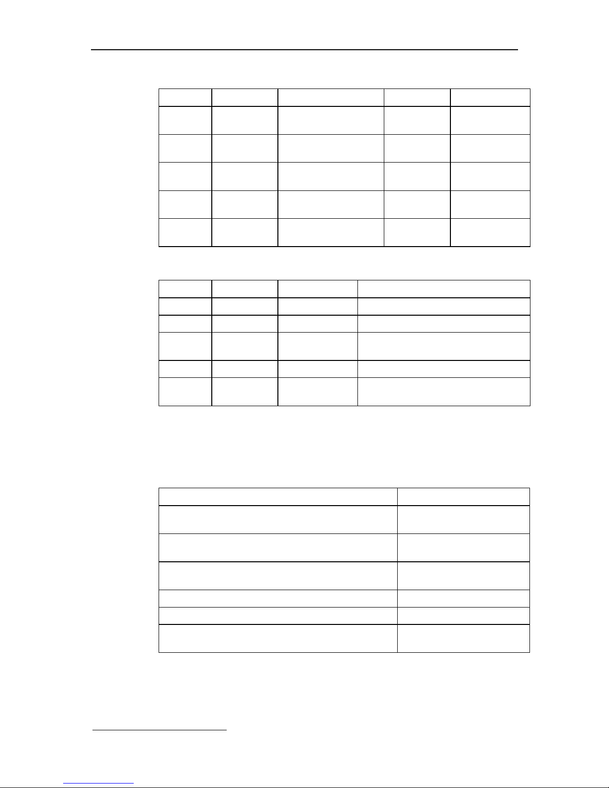
Alarm is acknowledged while alarm condition is still present
Setting Alarm trips Reset pressed Alarm clears Reset pressed
DNAK
1
Relay trips Alarm acknowledged
Relay stays tripped
Relay clears No effect
LNAK
1
Relay trips Alarm acknowledged
Relay stays tripped
No effect Relay clears
NAK
1
Relay trips Alarm acknowledged
Relay stays tripped
Relay clears No effect
LACK
1
Relay trips Alarm acknowledged
Relay clears
No effect No effect
ACK
1
Relay trips Alarm acknowledged
Relay clears
No effect No effect
Alarm is not acknowledged
Setting Alarm trips Alarm clears Reset pressed
DNAK
1
Relay trips No effect Alarm acknowledged; relay clears
LNAK
1
Relay trips No effect Alarm acknowledged; relay clears
NAK
1
Relay trips Relay clears Alarm acknowledged; relay stays
cleared
LACK
1
Relay trips No effect Alarm acknowledged; relay clears
ACK
1
Relay trips Relay clears Alarm acknowledged; relay stays
cleared
Relays configured “Single” and “LNAK1”
Relays configured Single and LNAK1 must be acknowledged at the relay display card
or master card, by pressing Reset or through remote reset input, if the channel card
gas alarm is acknowledged at the channel card before the gas alarm clears.
Event Relay (alarm) state
Gas alarm trips on channel card Relay in alarm state.
Tripped LED flashes
Channel card acknowledged Relay in alarm state.
Tripped LED on
Gas level falls below trip point Relay in alarm state
Tripped LED Off
Channel card acknowledged No change
Subsequent channel card acknowledgement No change
Reset pressed on relay display card or master card Relay in non alarm state.
Tripped LED off
1
See explanation of relay configuration options on page 25
Page 10
REGARD Relay Module & Relay Display Card (ATEX version)
Issue 1 – July 2003
10
Operational faults
An operation fault is a failure in the operation of either the relay display card or the
relay module. Operational faults are either:
• critical – card may stop working, or
• advisory – card will continue to work safely, but its functions may be limited
When an operational fault occurs:
• Power LED flashes once a second
• If fault is critical, operational fault relay de-energises
• Display shows fault code alternately with normal display
Press Reset to clear the fault. If fault will not clear, or recurs, call Draeger Service.
Operational fault codes
Fault code Meaning Remedy
FAULT BR
FAULT Bñ
FAULT Bò
FAULT Bï
FAULT Bð
Push button key fault. Advisory.
One of the front panel push button keys appears to
be continuously pressed.
Check push button keys.
FAULT C
Communications failure – Regard. Critical.
Relay display card is not receiving data from the
Regard master card. Alarms will not activate
relays. (See below for a fuller explanation.)
Check the integrity of the RS485 connections between the
relay display card, master card
and all channel cards.
FAULT CM
Communications failure – module. Critical.
One or more relay modules are not acknowledging
messages from the display card. (Modules may be
receiving data, but this cannot be confirmed.)
Relays may not operate.
Check module number.
Check RS-485 connection to
relay modules.
FAULT DR
FAULT DC
Relay or Card Data error. Critical.
Configuration settings have been corrupted.
Default configuration settings will be used.
Relays may not operate.
Check configuration settings.
FAULT HV
Supply voltage too high. Critical.
Reduce supply voltage.
FAULT LV
Supply voltage too low. Critical.
Increase supply voltage.
FAULT Mx
Microcontroller failure. Critical.
Card/module has stopped working.
Hold down Reset to reset the
card.
FLTMC nn
Module Communications failure. Advisory.
Module number nn is not receiving data from the
relay display card. All relays on module will
automatically de-energise.
Check module Nos. Check RS485 connection to relay
modules.
FLTMB nn
Relay module DC supply brownout. Critical.
Fault in DC supply to relay module number nn.
Check power supply to relay
module.
FLTMW nn
Relay module watchdog reset. Advisory.
An unknown error has caused relay module
number nn to reset.
Check relay module
installation.
FAULT RR
Remote reset fault. Advisory.
Remote reset terminals appear to be continuously
shorted. The remote reset input will be ignored.
Check remote reset.
FAULT Wi
FAULT We
Watchdog reset. Advisory.
Unknown error caused card to reset. Card will
continue to operate normally.
Check relay display card
installation.
Page 11

REGARD Relay Module & Relay Display Card (ATEX version)
Issue 1 – July 2003
11
In the situation where multiple faults occur consecutively, the first fault to occur will be
displayed. When that is cleared subsequent faults may be displayed if they are
unaffected by the clearing of prior faults.
In the situation where multiple faults occur simultaneously, only one will be indicated
on the display. The fault states are monitored continuously in the following order:
FAULT DR, DC, C, CM, HV, LV, BR, Bñ, Bò, Bï, Bð, FLTMC, FLTMB and FLTMW.
Any of these may be overridden by the hardware exception faults Mx, Wi and We
WARNING - FAULT C indication on the relay display card
The relay display card (RDC) is designed to listen to communications between
the master card and channel cards. A FAULT C indication will be indicated on
the RDC if:
§ there is no valid communication between the master card and at least one
channel card,
§ the communication link to the RDC is broken,
§ the checksum setting is not consistent throughout the system.
On a system with more than one channel the RDC will appear to be working
normally providing that at least one channel is communicating correctly with
its master card. Channels not communicating correctly will not generate
alarms, however, these channels will exhibit communication faults either on
the channel card itself or on the master card.
WARNING - FLTMB indication on the relay display card
The relay module initiates a brown-out indication on the RDC at voltages much
lower than the minimum specification. It is possible for the relay module to
malfunction due to a low supply voltage without this fault appearing on the
RDC.
Loss of communication between relay display card and relay module(s)
If the RS-485 connection between the relay display card and a relay module is
broken, or the communications between the two is otherwise interrupted, all
relays on the relay module will de-energise.
• There is a delay of 5 seconds, after the connection is broken, before the relays deenergise. If the connection is re-made within 5 seconds, the relays do not deenergise.
• When the connection is re-made, the relays will stay de-energised for 10 seconds.
Page 12
REGARD Relay Module & Relay Display Card (ATEX version)
Issue 1 – July 2003
12
INSTALLATION
Handle circuit boards with care during installation. Do not touch the circuit boards or
components.
Use of the relay modules and relay display card requires a Regard master card. All
Regard channel cards (e.g. 4-20, Ex, HART, 8-channel) must be connected to the
same RS-485 bus as the relay display card and the master card.
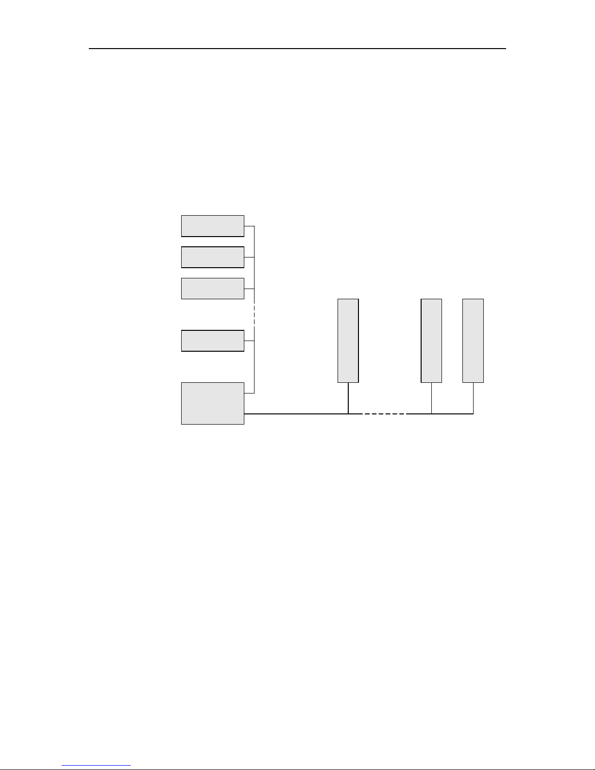
The diagram below shows how the relay display card and relay modules connect to a
Regard system. Note that there is a separate RS-485 bus from the relay display card
to the relay modules. (Diagram for illustration only.)
RELAY
DISPLAY
CARD
RELAY MODULE
RELAY MODULE
RELAY MODULE
MASTER
CARD
CHANNEL 1
CHANNEL 2
CHANNEL 99
MAIN RS-485 BUS
RS-485 BUS TO RELAY MODULES
Install relay display card
Fit the relay display card in slot in Regard rack.
EMC! Tighten the screws on the front panel fully.
Install relay modules
EMC! Install the relay module in a metal enclosure or other enclosure which gives protection
against radio-frequency interference.
• Fit relay modules to 35mm symmetric or 32mm asymmetric DIN rail.
• Maximum cable length of the RS-485 bus must not exceed 1000m
• Voltage difference between 0V at the relay display card and all relay module must
not exceed 5V. Use an RS-485 isolator if the voltage difference is greater that 5V.
Page 13
REGARD Relay Module & Relay Display Card (ATEX version)
Issue 1 – July 2003
13
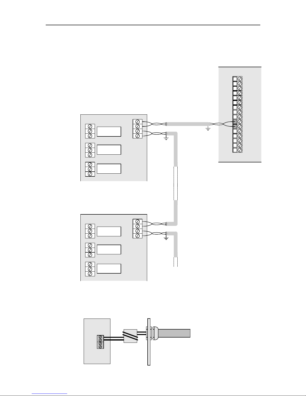
• Connect “A” on relay module to “A” on relay display card (terminal 11 on Regard
rack)
• Connect “B” on relay module to “B” on relay display card (terminal 10 on Regard
rack)
1
2
3
5
4
6
7
8
9
10
11
12
13
14
15
16
B
A
REGARD RACK
BABABABA
RELAY MODULE
RELAY MODULE
EMC! Use screened twisted pair cable. If the RS-485 cable between the relay module and
relay display card is outside the enclosure, pass the cable through a ferrite tube at the
entry point to the enclosure.
A
B
Page 14

REGARD Relay Module & Relay Display Card (ATEX version)
Issue 1 – July 2003
14
Allowed connection arrangements
“Bus”
RELAY
DISPLAY
CARD
RELAY MODULE
RELAY MODULE
MAXIMUM CABLE LENGTH: 1000m
RELAY MODULE
“Bus” with “stubs”
• Maximum allowed length of a stub is 5m
<1000m
RELAY
DISPLAY
CARD
RELAY MODULE
RELAY MODULE
RELAY MODULE
RELAY MODULE
<5m
<5m
<1000m
RELAY
DISPLAY
CARD
RELAY MODULE
RELAY MODULE
RELAY MODULE
RELAY MODULE RELAY MODULERELAY MODULE
Page 15

REGARD Relay Module & Relay Display Card (ATEX version)
Issue 1 – July 2003
15
Disallowed connection arrangements
“Star” – NOT ALLOWED
RELAY
DISPLAY
CARD
RELAY MODULE
RELAY MODULE
RELAY MODULE
RELAY MODULE
“Tree” – NOT ALLOWED
RELAY
DISPLAY
CARD
RELAY MODULE
RELAY MODULE
RELAY MODULE
RELAY MODULE
RELAY MODULE
Set module numbers
Set the ID number of each module using the rotary switch (SW1) on the module.
SW1
Each module connected to a relay display card must have a unique ID number.
• First module must be 0
• ID numbers must be contiguous– do not leave any gaps in the sequence.
Examples:
• 3 relay modules, numbers 0, 1, 2.
• 16 relay modules: numbers 0, 1, 2, 3, 4, 5, 6, 7, 8, 9, A, B, C, D, E, F.
• Relay modules are identified by the relay display card as “ID number + 1”, e.g. the
module with ID number 0 will be module 1 on the relay display card.
• The order of the relay modules on the RS-485 bus does not affect the operation of
the relay modules. Using a logical numbering sequence for the modules makes
programming the relay display card easier.
Page 16

REGARD Relay Module & Relay Display Card (ATEX version)
Issue 1 – July 2003
16
Connect equipment to relay terminals
Normally-open and normally-closed contacts are labelled on the relay module.
Labels show function of relay when de-energised:
NC NOC
EMC! Use screened cable for connections to relays
Connect DC supply to modules
Connect 24V DC supply to terminals marked 24V and 0V. Observe the polarity of the
terminals. Second pair of terminals can be used to connect supply to another relay
module.
• Do not connect more than 4 modules in series.
• Do not switch on 24V supply to relay modules until installation is complete.
24V
0V
Page 17

REGARD Relay Module & Relay Display Card (ATEX version)
Issue 1 – July 2003
17
Optional connections
Remote reset
If required, connect normally-open contact to remote reset terminals on relay display
card to allow remote reset of alarm relays. Connect using screw terminals on Regard
rack.
EMC! Use screened cable.
REGARD RACK
1
2
3
5
4
6
7
8
9
10
11
12
13
14
15
16
Operational fault relay
Use operational fault relay on relay display card to provide warning signal of failure
of relay display card. Connect using screw terminals on Regard rack.
EMC! Use screened cable.
REGARD RACK
1
2
3
5
4
6
7
8
9
10
11
12
13
14
15
16
RELAY SHOWN
ENERGIZED
(NORMAL STATE)
Page 18

REGARD Relay Module & Relay Display Card (ATEX version)
Issue 1 – July 2003
18
Switch-on and initial checks
Switch on DC supply to the relay display card and the relay module(s).
Check that the Power LED on the relay display card and relay modules are lit.
If power to the relay modules is connected more than 5 seconds before the relay
display card, the relay display card will indicate a communications fault warning.
Press R push button to cancel the warning.
Relay display card may indicate a fault condition until it is correctly configured.
Page 19

REGARD Relay Module & Relay Display Card (ATEX version)
Issue 1 – July 2003
19
CONFIGURATION
Command mode
Configuration and maintenance of the display card is performed using front panel
controls and display, by setting the card into command mode.
Command mode is entered by pressing and holding the Reset button for about 5
seconds.
In command mode:
• Display of relays status is replaced by display of command mode options and
configuration settings;
• The Inhibit LED lights and the Fault relay trips to indicate that operation of all
relays on relay modules is prevented (“inhibited”).
Configuration and maintenance commands are operated by selecting the command
number using the and push buttons.
Entering command mode automatically inhibits all alarm relays on the module(s)
connected to the relay display card.
Function of front panel controls in command mode
Push buttons
Push button Function
R
Confirm entry or selection
Select next command or option
Increase displayed value
Select previous command or option
Decrease displayed value
Select next relay
Select previous relay
SHIFT +
Jump +16 relays
SHIFT +
Jump –16 relays
Display
LED State Meaning
Alarm
Off
On
Relay not in alarm state
Relay in alarm state
Tripped
Off
On
No alarm
Alarm condition true
Power
On
Flashing
DC power on
Operational fault
Inhibit
On
Blinking
Relays inhibited
Relays inhibited + relays disabled
Page 20

REGARD Relay Module & Relay Display Card (ATEX version)
Issue 1 – July 2003
20
Table of commands
Cmd Command Function Command mode level Default
No. name Read Maint. Config. setting
00–0 CMD QUIT Quit command mode
• • •
00–1 PASSWORD Enter password
• • •
00–3 CHG P.WD Change password
• •
04–4 RLY ENER Set relay normally energised or
energise on alarm
o
•
NORM
†
11–1 VOTING Set relay voting configuration o
•
11–4 RLY MODE Set relay mode: common, voted, single
or no operation
o
•
NOP
†
11–7 LATCHING
Set relay latching, non-latching,
delay-latching, acknowledgeable,
non-acknowledgeable
o
•
LACK
14–0 LED TEST Test display & LEDs
• • •
14–1 RMT TEST Test remote reset
• • •
14–2 OPR TEST Test operational fault relay
• •
14–4 RLY TEST Test relay operation
• •
14–8 MOD TEST Test communications with modules
• • •
52–0 MODULES Set number of relay modules o o
•
1
52–1 CARD NUM Set relay display card number o o
•
1
52–6 CHECKSUM Set communications checksum
•
CRC
60–1 DISPLAY Turn display on or off
•
ON
60–4 DISABLE Disable relay
• •
NO
• Command can be accessed and setting changed
o Command can be accessed but setting cannot be changed
†
Relays with mode NOP will always be de-energised.
There is no SAVE command on the relay display card (00-2). Settings are saved automatically.
The relay display card does not automatically exit command mode if no buttons are pressed for 10
minutes. There is no LOCK command (60-0) to lock the card in command mode.
Page 21

REGARD Relay Module & Relay Display Card (ATEX version)
Issue 1 – July 2003
21
Configure channel cards and master card
Before configuring relay display card ensure that the other components of the Regard
system are correctly configured:
• Set operation of Regard master card and channel cards (4-20, Ex, HART, 8channel, etc.)
• Regard Master card must be configured to communicate with all channel cards
that will control alarms on relay module(s).
Configure relay display card
Use the blank sheets at the end of this manual to plan and record the configuration of
the relay modules.
Example
Card No. 1
Module No. 1
Relay No. Mode (11-4) Voting (11-1) Latching (11-7) Energise (04-4)
1 CA1 — ACK ENER
2 CA2 — ACK ENER
3 CA3 — ACK ENER
4 CF — LNAK NORM
5 SA1 CH1 — ACK ENER
6 SA2 CH1 — ACK ENER
7 SA3 CH1 — ACK ENER
8 SA1 CH2 — ACK ENER
9 SA2 CH2 — ACK ENER
10 SA3 CH2 — ACK ENER
11 SA1 CH3 — ACK ENER
12 SA2 CH3 — ACK ENER
13 SA3 CH3 — ACK ENER
14 SF CH1 — LNAK NORM
15 SF CH2 — LNAK NORM
16 SF CH3 — LNAK NORM
Card No. 1
Module No. 2
Relay No. Mode (11-4) Voting (11-1) Latching (11-7) Energise (04-4)
17 VA1 01 02 03 LACK ENER
18 VA2 01 02 03 LACK ENER
19 VA3 01 02 03 LACK ENER
.
.
.
.
.
.
.
.
.
.
.
.
.
.
.
Page 22

REGARD Relay Module & Relay Display Card (ATEX version)
Issue 1 – July 2003
22
Configuration sequence
Enter configuration-level password
Factory-set configuration password is CCCC.
00–1 PASSWORD
PRESS DISPLAY
• Select 00–1
00-1
• Enter command
R PASSWORD
then
Ready for password entry
????
• Select first letter of password
C???
• Confirm first letter
R CC??
• Enter 2nd 3rd and 4th letters of password
R
CCCC
• Enter
Access at configuration level confirmed
R CONFIG
then
Command ends
00-1
Set number of relay modules
Set the number of relay modules connected to the relay display card.
52-0 MODULES
PRESS DISPLAY
• Select 52-0
52-0
• Enter command
R MODULES
then
Current setting:
1
• Select number of modules, e.g. 3
3
• Exit command
R 52-0
Page 23

REGARD Relay Module & Relay Display Card (ATEX version)
Issue 1 – July 2003
23
Set function of relays
11–4 RLY MODE
PRESS DISPLAY
• Select 11-4
11-4:001
• Enter
R RLY MODE
then
Current setting:
001:NOP
Relay number
Function
• Select function e.g. CA1
001:CA1
If SA1, SA2, SA3 or SF function selected, extra
step required (see below)
• Select next/previous relay and repeat
010:CA1
• Enter
R 11-4:010
For “Single” function:
• Select function SA1, SA2, SA3 or SF
001:SA1
• Enter
R 001:CH1
Channel number
• Select channel number
001:CH2
• Select next/previous relay and repeat
002:CA1
WARNING – it is possible to select channel numbers which are not present in the system and
the display card will not indicate that this setting is invalid.
Code Meaning Relay operation
CA1 Common A1
Alarm when A1 alarm on any channel.
CA2 Common A2
Alarm when A2 alarm on any channel.
CA3 Common A3
Alarm when A3 alarm on any channel.
CF Common Fault
Alarm when Fault alarm on any channel.
SA1 Single A1
A1 alarm for one channel.
SA2 Single A2
A2 alarm for one channel.
SA3 Single A3
A3 alarm for one channel.
SF Single Fault
Fault alarm for one channel.
VA1 Voted A1
Alarm when n out of m A1alarm on selected channels.
VA2 Voted A2
Alarm when n out of m A2alarm on selected channels.
VA3 Voted A3
Alarm when n out of m A3alarm on selected channels.
VF Voted Fault
Alarm when n out of m Fault alarm on selected channels.
NOP No operation None (relay always de-energised)
Page 24

REGARD Relay Module & Relay Display Card (ATEX version)
Issue 1 – July 2003
24
Set voting configuration
For relays configured voting (i.e. VA1, VA2, VA3 or VF), use command 11–1 to set
voting information for each relay.
Example 2 out of 3 voting for channels 4, 6 and 9.
11-1 VOTING
PRESS DISPLAY
• Select 11-1
11-1:001
• Enter
R VOTING
then
Current setting:
n OF 1
Number of channels in voting group (m)
• Select value of m (e.g. 3)
n OF 3
• Enter
R 1 OF 3
No of alarms required to trip (n)
• Select value of n (e.g. 2)
2 OF 3
• Enter
R 1 CH1
First channel in voting group
Channel number
• Select first channel in voting group (e.g. 4)
1 CH4
• Enter
R 2 CH5
Second channel in voting group
Channel number
• Select second channel in voting group (e.g. 6)
2 CH6
• Enter
R 3 CH7
• Select last channel in voting group
3 CH9
• Exit command
R 11-1:001
WARNING – it is possible to select channel numbers which are not present in the system and
the display card will not indicate that this setting is invalid.
Page 25

REGARD Relay Module & Relay Display Card (ATEX version)
Issue 1 – July 2003
25
Set relay latch/acknowledge operation
Determines the operation of a relay when the alarm condition clears or when the relay
alarm is acknowledged.
WARNING – when a relay latch mode is set to ACK or LACK, a tripped relay can
be cleared even though an alarm condition may still be present. These latch
modes are generally employed as a convenience to silence audible alarms
while the problem is being addressed.
Mode Function
ACK Non Latching and Acknowledgeable
Relay returns to non-alarm state when the relay alarm condition has cleared
or the relay alarm has been acknowledged.
NAK Non Latching and Non Acknowledgeable
Relay returns to its non-alarm state when the relay alarm condition has
cleared. Acknowledging the relay alarm whilst the alarm condition is still
true will not reset the relay.
LACK Latching and Acknowledgeable
Relay returns to its non alarm state when the relay alarm is acknowledged.
The relay will not automatically go back to its non-alarm state when the
alarm condition stops.
LNAK Latching and Non Acknowledgeable
Returns to its non alarm state when the alarm condition stops and then the
alarm is acknowledged. Acknowledging the relay alarm whilst the alarm
condition is still true will not reset the relay. The relay will not automatically
go back to its non-alarm state when the alarm condition stops.
DNAK
Delay Latching and Non-Acknowledgeable
Relay returns to its non alarm state when the alarm condition stops and the
alarm has been acknowledged. Acknowledging the relay alarm whilst the
alarm condition is still true will not reset the relay. The relay will
automatically go back to its non-alarm state when the alarm condition stops
if the relay has already been acknowledged.
11-7 LATCHING
PRESS DISPLAY
• Select 11-7
11-7:001
• Enter
R LATCHING
then
Current setting:
001:LACK
• Select new setting (e.g. ACK)
001:ACK
• Select next/previous relay until setting for all
relays configured
002:DNAK
• Exit command
R 11-7:002
Page 26

REGARD Relay Module & Relay Display Card (ATEX version)
Issue 1 – July 2003
26
Set relays energise on alarm or normally energised
04–4 RLY ENER
PRESS DISPLAY
• Select 04-4
04-4:001
• Enter
R RLY ENER
then
Current setting:
001:NORM
• Select NORM or ENER, e.g. ENER*
001:ENER
• Select next/previous relay and repeat
005:ENER
• Exit command
R 04-4:005
* NORM = Normally energised ENER = Energise on alarm
Set communications checksum
The relay display card must use the same communications checksum for RS-485
communications as the rest of the Regard system. Use CRC whenever possible.
52-6 CHECKSUM
PRESS DISPLAY
• Select 52-6
52-6
• Enter command
R CHECKSUM
then
Current setting:
CRC
• Select mode, e.g. CSUM
CSUM
• Exit command
R 52-6
Quit command mode
00-0 QUIT
PRESS DISPLAY
• Select 00–0
00-0
• Enter
R QUIT:NO
• Select YES
QUIT:YES
• Enter
Card exits command mode
R 001:CLR
Page 27

REGARD Relay Module & Relay Display Card (ATEX version)
Issue 1 – July 2003
27
Optional configuration settings
Set relay display card number
To allow remote configuration, each relay display card must be assigned a unique
card number.
Note: This setting allows differentiation of relay display cards on the same RS-485
bus by remote configuration software. It does not affect the operation of the relay
display card or relay modules in any way.
52-1 CARD NUM
PRESS DISPLAY
• Select 52-1
52-1
• Enter
R CARD NUM
then
Current setting:
CARD:1
• Select card number, e.g. 2
CARD:2
• Exit command
R 52-1
Turn display off
To save power, the display can be turned off. Display is then blank unless a relay is in
alarm or a button is pressed.
60–1 DISPLAY
PRESS DISPLAY
• Select 60-1
60-1
• Enter
R DISPLAY
then
Current setting:
ON
• Select ON or OFF, e.g. OFF
OFF
• Exit command
R 60-1
Page 28

REGARD Relay Module & Relay Display Card (ATEX version)
Issue 1 – July 2003
28
MAINTENANCE
Recommended maintenance intervals
EN 50073 and respective national regulations should be observed.
Daily:
• Visual check to determine readiness for operation
At regular intervals:
• Inspection by trained personnel.
The inspection intervals in each individual case are subject to technical safety
considerations, engineering processes and the technical requirements for the
equipment. A maximum interval of three months is recommended.
• Check connections to relays and between modules and relay display card
• Check operation of relays (command 14-4)
Page 29

REGARD Relay Module & Relay Display Card (ATEX version)
Issue 1 – July 2003
29
Commands for system maintenance
Change password
• Factory-set maintenance password is MMMM.
• Factory-set configuration password is CCCC.
• To change Configuration-level password, use command 00–3 after entering
existing Configuration-level password
• To change Maintenance-level password, use command 00–3 after entering
existing Maintenance-level password.
• Password must be 4 characters.
Example: change configuration password to ABCD.
00–3 CHG P.WD
PRESS DISPLAY
• Select 00–3
00-3
• Enter
R CHG P.WD
then
Existing password
CCCC
• Select first letter of new password
ACCC
• Enter
R AACC
• Select second letter
ABCC
• Enter
R ABBC
• Select third letter
ABCC
• Enter
R ABCC
• Select the fourth letter
ABCD
• Enter (NEW indicates new password)
R CFG:NEW
then
Command exits
00-3
Page 30

REGARD Relay Module & Relay Display Card (ATEX version)
Issue 1 – July 2003
30
Test LEDs and display
14-0 LED TEST
PRESS DISPLAY
• Select 14-0
14-0
• Press R to test
R LED TEST
LEDs and display flash
• Press R to stop
R 14-0
Test remote reset
14–1 RMT TEST
PRESS DISPLAY
• Select 14-1
14-1
• Enter
R RMT TEST
then
Remote reset terminals closed-circuit
CLOSED
or
Remote reset terminals open-circuit
OPEN
or
Remote reset terminals closed-circuited for more
than 20 seconds
FAULTY
• Press R to stop
R 14-1
Test operational fault relay
14–2 OPR TEST
PRESS DISPLAY
• Select 14-2
14-2
• Enter
R OPR TEST
then
Relay in non alarm state
OFF
or
Relay in alarm state
ON
• Change relay state
OFF
• Exit command
R 14-2
Page 31

REGARD Relay Module & Relay Display Card (ATEX version)
Issue 1 – July 2003
31
Test relay module relay
14–4 RLY TEST
PRESS DISPLAY
• Select 14-4
14-4:001
• Enter
R RLY TEST
then
If relay not energised
001:OFF
or
If relay energised
001:ON
• Change relay state
001:ON
• Select next/previous relay
002:OFF
• Exit command
R 14-4:002
Test communications with relay modules
14–8 MOD TEST
PRESS DISPLAY
• Select 14-8
14-8
• Enter
R MOD TEST
then
Checking communication with relay module 1
MOD1 ??
then
Communications okay
MOD1 OK
or
No communications with module
MOD1 NO
• Select next/previous module
MOD2 OK
• Exit command
R 14-8
Page 32

REGARD Relay Module & Relay Display Card (ATEX version)
Issue 1 – July 2003
32
Disable relay(s)
Each relay on the relay modules can be prevented from changing state when an
alarm occurs.
If a relay that is in its alarm state is disabled, the relay will change to its non-alarm
state upon exit from command mode.
The “Inhibit” LED blinks when one or more relays are disabled.
For disabled relays:
• “Tripped” LED continues to indicate that alarm condition is true
• “Alarm” LED does not operate.
Warning: a disabled relay will not indicate a gas alarm or fault alarm.
60-4 DISABLE
PRESS DISPLAY
• Select 60-4
60-4:001
• Enter
R DISABLE
then
Current setting:
001:NO
• Select YES (disabled) or NO (not disabled)
001:YES
• Select next/previous relay
003:YES
• Exit command
R 60-4:003
Page 33

REGARD Relay Module & Relay Display Card (ATEX version)
Issue 1 – July 2003
33
TECHNICAL DATA
Relay display card
Supply voltage 18 to 35V DC
Environmental operating range
• Temperature
–20° to +55°C
• Humidity
0 to 90%RH, non-condensing
• Vibration
To BS 2011 Part 2.1Fc
Storage temperature range –25° to +70°C
Current consumption
• Typical
50mA
• Maximum
150mA
Operation fault relay
• Type
Single pole double throw (1 Form C)
• Switching capacity
5A, 250VAC; 5A 30VDC
• Max. switching power
1,250VA, 150W
• Max. switching voltage
250VAC, 100VDC
• Min. switching voltage & current
12V, 100mA
Format Single Eurocard, 10 HP front panel
Dimensions 187 x 129 x 50mm
Fuse 800mA quick blow (F), 20 x 5mm
Relay module
Supply voltage 18 to 35V DC
Environmental operating range
• Temperature
–20° to +55°C
• Humidity
0 to 90%RH, non-condensing
• Vibration
To BS 2011 Part2.1Fc
Storage temperature range –25° to +70°C
Current consumption
• Typical
50mA
• Maximum
350mA
Relays
• Type
Single pole double throw (1 Form C)
• Switching capacity
5A, 250VAC; 5A 30VDC
• Max. switching power
1,250VA, 150W
• Max. switching voltage
250VAC, 100VDC
• Min. switching voltage & current
12V, 100mA
Wire cross-section
• Relays
2.5 mm
2
• DC inputs & RS-485
1.5 mm
2
Format DIN rail mounting module
Dimensions 360 x 90 x 60mm
Fuse 1A quick blow (F) 20 x 5mm
Note that for both the display card and the input module, type-examination covers:
• operating temperatures: 0 to +55°C
• storage temperatures: –25° to +55°C
Part numbers
Description Part Number
Regard relay display card (ATEX version) 4206719
Regard relay module (ATEX version) 4206720
Page 34

REGARD Relay Module & Relay Display Card (ATEX version)
Issue 1 – July 2003
34
EC-Type Examination certificate
Page 35

Relay module configuration sheet
Card No.
Module No. 1
Relay No. Mode (11-4) Voting (11-1) Latching (11-7) Energise (04-4)
1
2
3
4
5
6
7
8
9
10
11
12
13
14
15
16
Card No.
Module No. 2
Relay No. Mode (11-4) Voting (11-1) Latching (11-7) Energise (04-4)
17
18
19
20
21
22
23
24
25
26
26
28
29
30
31
32
Page 36

Relay module configuration sheet (contd.)
Card No.
Module No. 3
Relay No. Mode (11-4) Voting (11-1) Latching (11-7) Energise (04-4)
33
34
35
36
37
38
39
40
41
42
43
44
45
46
47
48
Card No.
Module No. 4
Relay No. Mode (11-4) Voting (11-1) Latching (11-7) Energise (04-4)
49
50
51
52
53
54
55
56
57
58
59
60
61
62
63
64
Page 37

Relay module configuration sheet (contd.)
Card No.
Module No. 5
Relay No. Mode (11-4) Voting (11-1) Latching (11-7) Energise (04-4)
65
66
67
68
69
70
71
72
73
74
75
76
77
78
79
80
Card No.
Module No. 6
Relay No. Mode (11-4) Voting (11-1) Latching (11-7) Energise (04-4)
81
82
83
84
85
86
87
88
89
90
91
92
93
94
95
96
Page 38

Relay module configuration sheet (contd.)
Card No.
Module No.
Relay No. Mode (11-4) Voting (11-1) Latching (11-7) Energise (04-4)
Card No.
Module No.
Relay No. Mode (11-4) Voting (11-1) Latching (11-7) Energise (04-4)
Page 39

Page 40

Draeger Safety UK Ltd
Kitty Brewster Industrial Estate
Blyth
Northumberland
NE24 4RG
England
Tel. +44 1670 352891
Fax +44 1670 356266
Dräger Safety AG & Co. KGaA
Revalstraße 1
D-23560 Lübeck
Germany
Tel. +49 4 51 882 - 2794
Fax +49 4 51 882 - 4991
Draeger Industrie S.A.
3c, route de la Fédération
F-67025 Strasbourg Cedex
France
Tel. +33 388 40 7676
Fax +33 388 40 7667
http://www.draeger.com/gds
Draeger Safety, Inc.
10450 Stancliff
Suite 220
Houston, TX 77099
U.S.A.
Tel. +1 281 498 1082
Fax +1 281 498 5190
Draeger South East Asia Pte, Ltd.
67, Ayer Rajah Crescent #06-03
SGP-0513 Singapore
Singapore
Tel. +65 6872 92 88
Fax +65 6773 20 33
Beijing Fortune Draeger Safety
Equipment Co. Ltd
22 Yu An Rd, B Area
Tianzhu Airport Industrial Zone
Houshayu
Shunyi District
Beijing 101300
PR China
Tel. +86 10 8049 8000
Fax. +86 10 8049 8005
Manual P/N 4206728
Issue 1 – July 2003
Subject to alteration
For use with relay display card software version D1.0 and V3.0
 Loading...