

Page 1

WARNING
Strictly follow the Instructions for Use.
The user must fully understand and strictly observe the
instructions. Use the product only for the purposes specified
in the Intended use section of this document.
Dräger Polytron 8700/8720
Instructions for Use
i
!
Page 2

Page 3

Contents
Contents
1 For your safety. . . . . . . . . . . . . . . . . . . . . . . . . . . . .4
1.1 General safety statements . . . . . . . . . . . . . . . . . . . .4
1.2 Definitions of alert icons . . . . . . . . . . . . . . . . . . . . . .4
2 Description . . . . . . . . . . . . . . . . . . . . . . . . . . . . . . . .5
2.1 Product overview . . . . . . . . . . . . . . . . . . . . . . . . . . .5
2.2 Functional description . . . . . . . . . . . . . . . . . . . . . . . .6
2.3 Intended use . . . . . . . . . . . . . . . . . . . . . . . . . . . . . . .6
2.4 Intended area and conditions of use . . . . . . . . . . . . .6
2.5 Approvals . . . . . . . . . . . . . . . . . . . . . . . . . . . . . . . . .6
2.6 Device marking . . . . . . . . . . . . . . . . . . . . . . . . . . . . .6
3 Installation . . . . . . . . . . . . . . . . . . . . . . . . . . . . . . . .7
3.1 General information for the installation . . . . . . . . . . .7
3.2 Restrictions on the installation . . . . . . . . . . . . . . . . .7
3.3 Impedance range of the signal loop . . . . . . . . . . . . .8
3.4 Mechanical installation . . . . . . . . . . . . . . . . . . . . . . .8
3.5 Electrical installation without e-Box . . . . . . . . . . . . . .8
3.6 Electrical installation with e-Box . . . . . . . . . . . . . . .10
3.7 Connecting the device to a Dräger control unit . . . .10
3.8 Connecting the device to a PC . . . . . . . . . . . . . . . .10
3.9 PolySoft 8000 PC software (optional) . . . . . . . . . . .10
3.10 Installing software dongles . . . . . . . . . . . . . . . . . . .10
4 Operation . . . . . . . . . . . . . . . . . . . . . . . . . . . . . . . .11
4.1 Operating fundamentals . . . . . . . . . . . . . . . . . . . . .11
4.2 Display and LEDs . . . . . . . . . . . . . . . . . . . . . . . . . .11
4.3 Activating the Info mode . . . . . . . . . . . . . . . . . . . . .12
4.4 Switching to the Quick Menu mode . . . . . . . . . . . .13
4.5 Switching to Menu mode (password protected) . . .13
4.6 Measurement mode . . . . . . . . . . . . . . . . . . . . . . . .13
5 Calibration . . . . . . . . . . . . . . . . . . . . . . . . . . . . . . .14
5.1 Calibrating the device . . . . . . . . . . . . . . . . . . . . . . .14
5.2 Performing Auto Calibration . . . . . . . . . . . . . . . . . .15
6 Menu overview . . . . . . . . . . . . . . . . . . . . . . . . . . . .16
7 Information menu. . . . . . . . . . . . . . . . . . . . . . . . . .17
7.1 Device settings . . . . . . . . . . . . . . . . . . . . . . . . . . . .17
7.2 Sensor information . . . . . . . . . . . . . . . . . . . . . . . . .17
7.3 Datalogger information (only with data dongle) . . .17
8 Settings menu . . . . . . . . . . . . . . . . . . . . . . . . . . . .18
8.1 Switching SIL lock on or off . . . . . . . . . . . . . . . . . . .18
8.2 Device settings . . . . . . . . . . . . . . . . . . . . . . . . . . . .18
8.3 Communication settings . . . . . . . . . . . . . . . . . . . . .21
8.4 Sensor settings . . . . . . . . . . . . . . . . . . . . . . . . . . . .24
8.5 Datalogger settings (only with data dongle) . . . . . .25
9 Troubleshooting. . . . . . . . . . . . . . . . . . . . . . . . . . .27
9.1 Fault reference: . . . . . . . . . . . . . . . . . . . . . . . . . . . .27
9.2 Warning reference . . . . . . . . . . . . . . . . . . . . . . . . .28
10 Maintenance . . . . . . . . . . . . . . . . . . . . . . . . . . . . . .29
10.1 Maintenance intervals . . . . . . . . . . . . . . . . . . . . . . .29
10.2 Changing the sensor . . . . . . . . . . . . . . . . . . . . . . . .29
10.3 Changing the main electronics . . . . . . . . . . . . . . . .29
11 Disposal . . . . . . . . . . . . . . . . . . . . . . . . . . . . . . . . 29
12 Substances in the gas library (PIR 7000). . . . . . 30
12.1 Polytron 8700 Type 334 . . . . . . . . . . . . . . . . . . . . 30
12.2 Polytron 8700 Type 340 . . . . . . . . . . . . . . . . . . . . 31
13 Technical data . . . . . . . . . . . . . . . . . . . . . . . . . . . 32
13.1 Torques . . . . . . . . . . . . . . . . . . . . . . . . . . . . . . . . . 33
13.2 Tightening torque and cable size for field wiring termi-
nals . . . . . . . . . . . . . . . . . . . . . . . . . . . . . . . . . . . . 33
13.3 Factory settings . . . . . . . . . . . . . . . . . . . . . . . . . . . 33
14 Order list . . . . . . . . . . . . . . . . . . . . . . . . . . . . . . . . 34
14.1 Dräger Polytron 8700 Type 334 . . . . . . . . . . . . . . 34
14.2 Dräger Polytron 8700 Type 340 . . . . . . . . . . . . . . 34
14.3 Dräger Polytron 8720 . . . . . . . . . . . . . . . . . . . . . . 34
14.4 Sensors for remote versions . . . . . . . . . . . . . . . . . 34
14.5 Replacement sensors (except for remote versions) 35
14.6 Accessories for Polytron 8700/8720 . . . . . . . . . . . 35
14.7 Replacement parts . . . . . . . . . . . . . . . . . . . . . . . . 35
15 Declaration of Conformity. . . . . . . . . . . . . . . . . . 36
Dräger Polytron 8700/8720 3
Page 4

For your safety
1 For your safety
1.1 General safety statements
z Before using the product, carefully read the Instructions
for Use.
z Strictly follow the Instructions for Use. The user must fully
understand and strictly observe the instructions. Use the
product only for the purposes specified in the Intended use
section of this document.
z Do not dispose of the Instructions for Use. Ensure that they
are retained and appropriately used by the product user.
z Only fully trained and competent users are permitted to use
this product.
z Comply with all local and national rules and regulations
associated with this product.
z Only trained and competent personnel are permitted to
inspect, repair and service the product as detailed in these
Instructions for Use. Further maintenance work that is not
detailed in these Instructions for Use must only be carried
out by Dräger or personnel qualified by Dräger. Dräger
recommend a Dräger service contract for all maintenance
activities.
z Properly trained service personnel must inspect and
service this product as detailed in the Maintenance section
of this document.
z Use only genuine Dräger spare parts and accessories, or
the proper functioning of the product may be impaired.
z Do not use faulty or incomplete products, and do not modify
the product.
z The threads for the explosion proof enclosure do not
conform to the minimum/maximum values in EN/IEC
60079-1. The threads must not be reworked by the user.
z The measuring function of the transmitter for explosion
protection according to Annex II, Clauses 1.5.5, 1.5.6 and
1.5.7 of Directive 94/9/EG is not covered at present.
z Only operate the product within the framework of a risk-
based alarm signalling concept.
Safe coupling with electrical devices
z Electrical connections to devices which are not listed in
these Instructions for Use should only be made following
consultation with the respective manufacturers or an
expert.
Use in areas subject to explosion hazards
z Devices or components for use in explosion-hazard areas
which have been tested and approved according to
national, European or international Explosion Protection
Regulations may only be used under the conditions
specified in the approval and with consideration of the
relevant legal regulations. The devices or components may
not be modified in any manner. The use of faulty or
incomplete parts is forbidden. The appropriate regulations
must be observed at all times when carrying out repairs on
these devices or components.
1.2 Definitions of alert icons
The following alert icons are used in this document to provide
and highlight areas of the associated text that require a greater
awareness by the user. A definition of the meaning of each
icon is as follows:
WARNING
!
IIndicates an imminently hazardous situation which, if
not avoided, will result in death or serious injury.
CAUTION
!
Indicates a potentially hazardous situation which, if not
avoided, could result in physical injury, or damage to
the product or environment. It may also be used to
alert against unsafe practices.
NOTICE
i
i
Indicates additional information on how to use the
product.
4 Dräger Polytron 8700/8720
Page 5

2 Description
001233300.eps
4
6
5
1
3
2
7
002233300.eps
4
8
5
1
6
7
3
2
2.1 Product overview
Description
2.1.1 Explosion proof device
2.1.2 Explosion proof device with increased safe wiring compartment (e-Box)
1 Housing cover
2 Clip
3 Enclosure with main electronics (and optional relay)
4 Lower part of housing
5 Dräger PIR 7000/7200
6 Assembled device
7 Mounting spacer
1 Housing cover
2 Clip
3 Enclosure with main electronics (and optional relay)
4 Lower part of housing
5 Dräger PIR 7000/7200
6 Feed through cable
7e-Box
8 Assembled device
Dräger Polytron 8700/8720 5
Page 6

Description
D
Polytron 8700
ITR 0421
Dräger Safety 23560 Lübeck, Germany
II 2G
II 2D
WARNING: Do not open when energized
I
S
F
S
I
E
A
D
L
C
9N54
0158
Class I, Div 1, Groups A,B,C,D | Class II, Div 1, Groups E,F,G
Class I, Zone 1, Group IIC | T-Code T6/T4 | Type 4X | C22.2 No. 152
Supply: 10...30 VDC, 0.1...0.75 A | Relays: 5 A, 30 VDC or 230 VA C
CAUTION: Do not open cover. Opening
cover with circuits alive provokes risk of
Ignition of Hazardous Atmospheres.
W
ARNING: To reduce the risk of Ignition
of Hazardous Atmospheres, the conduit
must be sealed within 18’’ of the enclosure.
WARNING: Read Manual before operating.
Gas Detector for Use in Hazardous Locations as to
Fire, Electrical Shock and Explosion Hazards only
Part No: 4544638
Serial No. XXXX-9999
Ex d IIC T6/T4 Gb
Ex tb IIIC T80/130°C Db
-40°C ≤ Ta ≤ +40/+80°C
PTB 11 ATEX 1005X
IECEx PTB 11.0005X
IP6x | P ≤ 5 W
Sample
2.2 Functional description
The device is operated from a 10 to 30 volt DC supply.
The current gas concentration, status messages and menu
items are shown on a backlit LCD display and by three colored
LEDs. The measured gas concentration is output as a 4 to
20 mA analog signal or a digital HART
®
signal1 After the power
is switched on, the device detects whether the 4-20 mA
interface is to be operated as a current source or a current
sink. The flexible design permits fitting even in places that are
difficult to access. The Dräger PIR 7000/7200 can be fitted on
either side of the of the equipment and installation with up to
30 m between the sensing head and the PIR 7000/7200 is
possible. In the variant with the integrated e-Box with the
"increased safety" protection class, the device can be easily
connected to the electrical field wiring. The device can be
configured, calibrated and serviced without declassification of
the area.
2.3 Intended use
The Dräger Polytron 87x0 is an explosion proof transmitter for
continuous monitoring of the concentration of gases and vapors
containing hydrocarbons or carbon dioxide. The housing for the
device consists of robust, non-corroding stainless steel or
aluminum and is suitable for indoor or outdoor applications.
The unit can be connected to a Dräger monitoring system or
a programmable logic controller (PLC) by means of a sealed
conduit or an appropriately approved cable gland. With the
optionally integrated relay module, the device can be operated
without a central controller (with additional local alarm
signalling). The device is designed for fixed installation and is
approved for use in potentially explosive atmospheres,
see chapter 2.5 on page 6.
2.3.2 Dräger Polytron 8720 with PIR 7200 infrared gas
sensor Type CO
2
For monitoring carbon dioxide.
z Measuring range (IDS 01x5): 0 to 0.2 up to 30 vol% CO
2
WARNING
!
Explosive. Not to be used in oxygen enriched
atmospheres. None of the Polytron 8000 transmitters
is certified and approved to be operated in oxygen
enriched atmospheres.
2.4 Intended area and conditions of use
Hazardous areas classified by zones:
The device is only designed for use in Zone 1 or Zone 2
potentially explosive atmospheres for which a temperature
range as specified on the device must be observed and in which
gases of Explosion Groups IIA, IIB or IIC and Temperature
Classes T4 or T6 (depending on maximum ambient
temperature) or dust of Groups IIIA, IIIB or IIIC may occur.
Hazardous areas classified by divisions:
The device is only designed for use in potentially explosive
atmospheres of Classes I&II, Div. 1 or 2, for which
a temperature range as specified on the device must be
observed and in which gases or dust of Groups A, B, C, D or
E, F, G and Temperature Classes T4 or T6 (depending on
maximum ambient temperature) may occur.
2.5 Approvals
WARNING
!
To prevent ignition of explosive atmospheres, strictly
follow the warnings below:
Not tested in oxygen enriched atmospheres (>21%
O2). High off-scale readings may indicate an explosive
concentration.
Exchanging components may compromise the intrinsic
safety. This only applies if the device is intrinsically
safe.
2.3.1 Dräger Polytron 8700 with PIR 7000 infrared gas sensor Types 334 and 340
For monitoring flammable gases and vapors containing
hydrocarbons
z Measuring range of Type 334 (IDS 01x1): 0 to 20 up to
100 %LEL
z Measuring range of Type 340 (IDS 01x2): 0 to 5 up to
100 %LEL
2
, for CH4 (methane) also 0 to 100 vol.%
2
See printed version for approval markings.
2.6 Device marking
The device marking is reproduced on a separate document
shipped with the device.
Key to the Serial Number: The third letter of the Serial Number
specifies the year of manufacture: A = 2009, B = 2010, C = 2011,
D = 2012, E = 2013, F = 2014, H = 2015, J = 2016, K = 2017 etc.
Example: Serial Number ARBH-0054: The third letter is B,
i.e. the device was manufactured in 2010.
2 Lower Explosive Limit depending on the substance and the locally
applicable regulations.
6 Dräger Polytron 8700/8720
1HART® is a registered trademark of HCF, Austin, Texas, USA
Page 7

Installation
3 Installation
3.1 General information for the installation
The selection of a suitable mounting location is crucial for the
effectiveness and performance of the entire system.
Considerable thought must be given to every detail of
installation, particularly:
z the local and national rules and regulations for the
installation of gas monitoring systems,
z the applicable regulations for running and connecting
power and signal cables to gas monitoring systems,
z the full extent of environmental influences to which the
device will be subjected,
z the physical properties of the gases and vapors to be
measured,
z the details of the particular application (e.g., potential
leaks, air movements/flows, etc.),
z accessibility for required maintenance activities,
z the geometric of the accessories that are used with
the system,
z all other limiting factors and stipulations that may affect the
installation of the system.
z For installation without a conduit, an approved cable gland
(e.g. Hawke A501/421/A/¾" NPT or equivalent) must be
used (see chapter 13 on page 32). To increase the RF
interference immunity, it may be necessary to connect the
cable screen to the cable gland and to the control unit.
z The explosion proof enclosure has three ¾" NPT
connections, which can be used for field wiring, the direct
attachment of a sensor or wiring an external sensor. For the
correct tightening torques for cable bushings, plugs and
sensors, see chapter 13 on page 32.
z The secondary are supposed to be supplied from an
isolating source (does not apply to relay contacts).
z The optional e-Box has up to four 20 mm connections,
which can be used for field wiring or wiring an external
sensor. The permissible cable diameter is 7 to 12 mm.
z If the device is installed in locations where ambient
temperatures of over 55 °C prevail, appropriate cables
which are designed for use at temperatures of 25 °C above
the maximum ambient temperature must be used.
z Strip back the insulation on conductors by 5 to 7 mm.
z Connect the cable as shown in Chapter 3.5 on page 8
(shown here also with protective ground).
z The use of a mounting spacer (Order Number 68 12 617)
is recommended as a matter of principle if the device is to
be mounted on a wall or on a very uneven substrate.
z The connecting wires for the optional relay module must be
selected and fused according to the rated voltages,
currents and environmental conditions.
z When stranded conductors are used, an end ferrule must
also be used.
3.2 Restrictions on the installation
z The device requires a DC voltage between 10 and 30 V.
The minimum supply voltage of 10 V and the cross-section
of the conductors used determine the distance of the
device from the supply or the central controller
(see chapter 13 on page 32). The device is designed for
cables of sizes 12 to 24 AWG (0.2 to 2.5 mm
2
). A three-
wire, screened cable must be used as a minimum.
z The device must not be subjected to any radiant heat
(e.g. direct sunlight) as this may result in a temperature rise
above the specified thresholds (see chapter 13 on
page 32). The use of a reflective screen is recommended.
z If a splash guard (Order Number 68 11 911 or 68 11 912) is
used, it is essential to make sure that the LEDs on the
status display are aligned vertically and the "Dräger" logo
on the splash guard is aligned horizontally. A maximum
deviation of ±10 degrees from the horizontal position is
permissible. Greater deviations will increase the response
time (see Instructions for Use for the PIR 7000/7200).
z Observe the preferred position: The PIR 7000/7200 must
be aligned so that the lights on the status display are above
one another. At the same time, the "Dräger" lettering on the
splash guard must read horizontally. A deviation from the
horizontal of ±10° maximum is permissible.
1
00333300.eps
z Any other alignment is only permissible if the PIR 7000/
7200 is used without a splash guard, e.g. applications in
exhaust ducts. When the sensor is fitted in an exhaust duct,
there is an increased risk that residues will form on the
optical surfaces.
z The housing is weather resistant and suitable for outdoor
applications. The use of the optional splash guard is
recommended to protect the sensor from water and dust.
z The device must be installed and operated in an
environment which conforms to the stated specifications
(see chapter 13 on page 32).
z To insure proper operation of the device, the impedance of
the 4 to 20 mA signal loop must not exceed 500 ohms.
Depending on the operating voltage and according to the
application (e.g. HART operation), certain minimum
impedances must be adhered to (see chapter 3.3 on
page 8). The conductors for the power supply must have
an adequately low resistance to insure the correct supply
voltage at the device.
Dräger Polytron 8700/8720 7
Page 8

Installation
01133300.eps
VDC
+
-
mA
01033300.eps
VDC
+
-
mA
NOTICE
i
i
A dust cap can be fitted to the cable entry of the device.
This cap is only used for transport purposes and must
be removed before the device is connected to a sealed
conduit.
3.3 Impedance range of the signal loop
Devices with a HART interface can be operated with HART
communication or in HART Multidrop mode.
Operating mode
Operation
without HART
communication
Operation with
HART
communication
(HART mode)
HART Multidrop
operation
Impedance range of the
signal loop
0 to 230 Ω at 10 V DC
Rising linearly with the
supply voltage from:
0 to 230 Ω at 10 V to
0 to 500 Ω at 16 V
0 to 500 Ω 18 to 30 V DC
230 to 270 Ω at 13 V DC
Rising linearly with the
supply voltage from:
230 to 270 Ω at 11 V to
230 to 500 Ω at 16 V
230 to 500 Ω 18 to 30 V DC
230 to 500 Ω 10 to 30 V DC
Supply
voltage range
10 to 18 V DC
11 to 16 V DC
3.5 Electrical installation without e-Box
CAUTION
!
First connect the cables for the relays and make
the connections to the sensor before connecting the
device to the power supply.
Connection diagram for operation as a current source
Connection diagram for operation as a current sink
3.4 Mechanical installation
z Use the supplied drilling template for mounting on a wall.
z The mounting surface should be even and free of
sharp edges.
z Dräger recommends using M6 Allen bolts.
z Take care that the conditions at the mounting location do
not result in the gas feed openings of the PIR 7000/7200
being covered or obstructed.
z The openings must be readily accessible to the
surrounding atmosphere.
NOTICE
i
i
There must be a free space of 5 cm next to the
PIR 7000/7200 to permit fitting/removal of the splash
guard and the later fitting of accessories.
To ensure an adequate distance between the
PIR 7000/7200 and the wall, use the mounting
spacer (Order Number 68 12 617).
8 Dräger Polytron 8700/8720
Page 9

Installation
00933300.eps
1
3.5.1 Power and signal cables
1. Release the retaining
screw (1) and unscrew the
housing cover from the
device.
2. Lift the handle and remove
the enclosure with the main
electronics.
3. Connect the device
electrically to ground.
4. Rotate the main electronics
and disconnect the 5-way
plug.
5. Connect the three cables for
the power supply and the
signal to the corresponding
terminals (see following
table of connections for the 5-way plug).
Connections for 5-way plug (power supply and signal):
5-way plug (power supply and signal)
Terminal 1 2 3 4 5
Ident. PWR+ PWR- PWR- 4 to 20 mA signal PE
Function V+ V- V- 4 to 20 mA signal
(Operation as
source or sink)
PE
NOTICE
i
i
For clear and far-ranging detection of a device fault,
an alarm device should be switched by the fault relay.
Connections for 9-way plug (relays):
9-way plug (relays)
Fault relay A2 relay A1 relay
Terminal123456789
Ident. FLTNOFLTCFLTNCA2NOA2CA2NCA1NOA1CA1
(NO = Normally open, NC = Normally closed, C = Common)
3.5.3 Remote sensor
The remote junction box (Order Number 45 44 098 for
stainless steel / Order Number 45 44 099 for aluminum)
permits the installation of the sensors remote from the device
electronics. This installation enables operation of the device in
difficult to access or unfavourable positions (see the
Instructions for Use for the Dräger Polytron 5000 Junction Box
in this respect). The maximum permissible distance between
the Polytron 87X0 and the PIR 7000/7200 is 30 m.
NC
6. For operation without a central controller: connect
Terminal 3 to Terminal 4.
7. Fit the plug back in the socket and tighten the screws.
8. The screen of the cable must only be connected to the
control unit.
9. Insert the main electronics back in the housing.
10. Screw the cover on again and tighten the retaining screw.
3.5.2 Version with relays
WARNING
!
At voltages >30 V AC or >42.4 V DC, the relay cables
must be enclosed in protective tubing, or doubleinsulated cables must be used.
When the relay module is fitted, the wires for the alarm device
are connected to the 9-way plug.
1. Disconnect the 9-way plug on the rear of the main
electronics.
2. Connect the wires for Alarm Relay 1, Alarm Relay 2 and the
Fault relay to the corresponding terminals, (see following
table of connections for the 9-way plug).
3. The relays are energized when the default settings are used
and in the measurement mode. This insures "fail-safe"
operation. The terminal assignments in the connection table
below apply when the default settings are used and in
measuring mode (see chapter 4.6 on page 13).
4. Fit the plug back in the socket and tighten the screws.
5. Fit the enclosed protective cover over the plug and secure
it with cable ties if necessary.
Dräger Polytron 8700/8720 9
Page 10

Installation
00833300.eps
3.6 Electrical installation with e-Box
z Install the e-Box in accordance with the Installation
Instructions for the Polytron 5000/8000 e-Box.
NOTICE
i
i
The e-Box can be pre-installed, wired and closed off
with the supplied cover. As soon as the installation is
ready for commissioning, the device is connected to
the e-Box and put into operation. This prevents the
device from being damaged during the construction
phase.
3.7 Connecting the device to a Dräger control unit
NOTICE
i
i
Information on connection can be found in the
Instructions for Use accompanying the particular
Dräger control unit (e.g. Regard, QuadGard).
Electrical connections to the control unit
z Connect the screen for the wires to the grounding point in
the control unit (e.g., chassis, grounding rail).
3.10 Installing software dongles
The following SW dongles are available for the device:
Datalogger dongle
83 17 618
Sensor test dongle
83 17 619
Diagnostic dongle
83 17 860
Combi-dongle (datalogger and sensor test dongle)
83 23 218
Combi-dongle (datalogger and diagnostic dongle)
83 23 219
Enables the datalogger and the
graphic display of concentrations.
Enables the sensor self test
(for certain versions only)
Enables the sensor self test,
the display of the remaining
sensor activity and the sensor
diagnostic function
(for certain functions only)
3.8 Connecting the device to a PC
The separately available Polytron 5000/8000 IR connection kit
is intended for use with the Polytron 5000/8000 and enables
communication between the Polytron 5000/8000 and a PC.
3.9 PolySoft 8000 PC software (optional)
The PolySoft 8000 PC software is used to display device
information, edit configuration settings and read out from the
measurements memory.
To install a SW dongle:
1. Switch off the power to the unit or declassify the area
according to the local regulations.
2. Release the retaining screw and unscrew the housing
cover from the device.
3. Lift the handle and remove the enclosure with the main
electronics.
4. Insert the dongle in the slot with the Dräger lettering facing
upwards.
5. Insert the main electronics back in the housing.
6. Screw the cover on again and tighten the retaining screw.
The dongle is installed.
7. Switch on the power.
10 Dräger Polytron 8700/8720
Page 11

Operation
M
OK
M
OK
M
OK
OK
OK
4 Operation
4.1 Operating fundamentals
4.1.1 Menu navigation
00733300.eps
It is possible to scroll throught he menu items by tapping the
and symbols with the magnetic wand (Part Number
4544101, blue). confirms a function.
NOTICE
i
i
The housing cover should be fitted when using the
magnetic wand. If the housing cover is not fitted,
the magnetic wand might activate two or more buttons
at the same time (crosstalk).
List closed below / complete
There are no further functions, menus or sub-menus
listed below.
List can be scrolled downwards
There are further functions, menus or sub-menus
listed below.
Next
Perform context-related action.
3/3
Number / total number of steps (screens) within
the function.
2/2
Entry
Enter data with » « and » «.
M
4.1.2 Changing parameter values or the parameter status
1. Select the desired menu item with and .
2. Confirm the menu item with .
The current value or status will be displayed.
3. Using and , the value of a numerical parameter can
be changed or preset values can be selected.
4. As soon as the desired value or the selection is displayed,
tap to validate/confirm the new parameter.
5. Tap to access the next higher level.
z If exiting using Back to menu or Previous, all changes will
be discarded.
4.1.3 Exiting menus
z Ta p Back to measurement and to exit the menu.
4.2 Display and LEDs
In measurement mode, the current gas concentration,
the name of the gas and the measurement units are shown on
the display. The green LED lights.
Graphic symbols facilitate navigation in the various menus.
Together with the text » Back «, » Menu «, etc., exit the
menu or go back 1 step.
Closed folder
Further functions or sub-menus are located under
this item.
Opened folder
The functions and sub-menus available here are listed
under this item.
Function
When activated, functions can be executed in one or
more steps.
Selection activated
For functions that can be selected and activated,
the activation is initiated by pressing » «.
OK
List closed above / complete
There are no further functions, menus or sub-menus
listed above.
List can be scrolled upwards
There are further functions, menus or sub-menus
listed above.
In addition, the following symbols may be displayed:
z " ", if the measurement range is exceeded
z " - - - - " and " X " in the event of a malfunction. The yellow
LED lights, (see chapter 4.2.2 on page 12).
z "SIL", when SIL status is activated.
When the optional relay PCB is used:
z If the first alarm has been triggered, the red LED gives
single flashes.
z If the second alarm has been triggered, the red LED gives
double flashes.
Dräger Polytron 8700/8720 11
Page 12

Operation
M
OK
4.2.1 Special symbols
The following special symbols, which indicate the device state,
may be displayed on the right hand side in measurement
mode.
Warning message present – to display warnings,
see chapter 7.1.1 on page 17.
Information can be called up in Info mode, see chapter 4.3
on page 12.
Error message present – to display the error,
see chapter 7.1.2 on page 17
Maintenance signal will be output on the interface,
see chapter 8.3.2 on page 21.
Measurement range of analog interface exceeded
Measurement less than range of analog interface
Analog interface is set to a fixed value (e.g. Multidrop HART
communication) and is not transmitting any measurements.
"Preventive" maintenance: The sensor is ready for operation.
"Preventive" maintenance: The sensor is ready for operation
but is close to the end of its life cycle.
"Preventive" maintenance: The sensor is still ready for
operation but should be changed as soon as possible.
The datalogger is active in rolling mode.
To activate/deactivate, see chapter 8.5.2 on page 25.
The datalogger is active in stacking mode.
To activate/deactivate, see chapter 8.5.2 on page 25.
SIL
SIL is activated (observe Safety Manual - Order Number
9033307).
4.2.2 LED symbols
Symbol LED Description
red Alarm triggered
yellow Malfunction / Warning
green
Switched on
Measurement mode
NOTICE
i
i
The alarm triggering function is only available when
the optionally integrated relay module is used.
When the optional relay PCB is used:
z If the first alarm has been triggered, the red LED gives
single flashes. A1 relay is activated.
z If the second alarm has been triggered, the red LED gives
double flashes. A2 relay is activated.
z If an alarm can be acknowledged and is acknowledged,
the LED stops flashing and lights continuously instead until
the alarm condition is no longer present. The corresponding
relay is deactivated.
4.3 Activating the Info mode
The Info mode is used to present information about the central
device settings and states.
z Tap and hold for 3 seconds.
The device information appears on several displays.
No changes can be made.
z Tap or briefly to switch between the displays.
z The Info mode can be ended at any time by selecting .
z If no button is selected within 30 seconds, the device
reverts automatically to the measurement mode.
Example of the Info mode
(Displays vary depending on sensor):
1. Display - Device information:
07.11.2003 12:34
SW Version
Part No.
Serial No.
DeviceCode: 00006317
Instrument Info
z Date and Time
z Software version
z Part number of the device
z Serial number of the device
z Device code
2. Display - Sensor information:
Sensorname: O
Part No. : 6809630
Serial No.
EEPROM Typ
EEPROM Vers.: 1
Sensor Info
z Sensor description
z Part number of sensor
z Serial number of the sensor
z Software version
z Software revision
3. Display - Sensor configuration:
Gasname : O
Range : 25.00 Vo
4–20 SP
Alarm A1
Alarm A2
Sensor Config.
z Gas description
z Maximum measurement limit and measurement units for
the sensor
z Measurement range and measurement units for the analog
interface. Only displayed when the 4-20 mA interface is
enabled.
: 1
: 8317778
: ARUA0001
2
: XXXXXXX
: 1
2
: 25.00 Vo
: 19.00 Vo
: 23.00 Vo
1/3
A001.eps
2/3
A002.eps
3/3
A003.eps
12 Dräger Polytron 8700/8720
Page 13

Operation
M
M
z A1 Alarm limit and measurement units
z A2 Alarm limit and measurement units
1
1
4.4 Switching to the Quick Menu mode
z Tap and hold for 1 to 2 seconds.
The Quick Menu will open. This menu is displayed without
any password request. No changes can be made.
The selected information about status and device settings
can be retrieved (e.g. warning messages, error messages,
installed modules and calibration data).
4.5 Switching to Menu mode (password protected)
1. Tap and hold for longer than 3 seconds.
The password request will be displayed.
2. Enter the password and confirm.
The screen for password entry will be displayed.
3. Set the password and confirm the entry.
The menu hierarchy corresponding to the entered password
will open.
z An error message will be displayed if the entered password
is invalid.
Password presets:
Password for the Calibration menu: _ _ _ 1
Password for the Settings menu: _ _ _ 2
4.6.1 Analog signals
In measurement mode the output current of the device is
between 4 and 20 mA and is proportional to the measured gas
concentration.
The device uses various current values to indicate different
operating modes. This conforms to the NAMUR NE43
recommendation. The 4-20 mA interface on the device can be
customized and configured to individual requirements.
The device is provided with suitable standard settings at the
factory (see chapter 13.3 on page 33).
4.6 Measurement mode
WARNING
!
The configuration and calibration settings must be
checked before the device is operated in measurement
mode.
z Switch on the power.
{ The device runs through a start-up sequence (LCD test
by inverting the video, LED test, software version and
initialization) and starts the warm-up phase. The display
indicates that the sensor is ready to start in hh:mm:ss
(the countdown begins) and the Polytron 87X0 sends
the Maintenance signal.
{ After the warm-up phase, the device passes into the
measurement mode.
{ The current gas concentration, the selected gas and
the units of measure appear on the display.
{ The LED lights green.
NOTICE
i
i
The correct date and time settings are important for
many functions (see chapter 8.2.3 on page 20).
1 Only displayed when relay is configured.
Dräger Polytron 8700/8720 13
Page 14
Calibration
5 Calibration
Repeat the calibration of the device at regular intervals as
specified in the particular sensor data sheet.
CAUTION
!
Danger to health! Do not inhale the test gas. Observe
the hazard information in the corresponding safety
data sheets. Provide venting into a fume cupboard or
outside the building.
Always calibrate the zero point first before the
sensitivity. Otherwise the calibration will be faulty!
NOTICE
i
i
Calibration is not possible if the date and time are not
set (see chapter 8.2.3 on page 20).
5.1 Calibrating the device
NOTICE
i
i
To perform a zero point or span calibration of the
Polytron 87X0 with a PIR 7000/7200, the PIR 7000/
7200 must be adequately warmed up. Dräger
recommends performing a calibration no sooner
than 3 hours after the device is switched on. For
a calibration, use the splash guard (Order Number:
68 11 911/68 11 912) and the calibration adapter
(Order Number: 68 11 610) (does not apply for duct
mounting or when the process cuvette / process
adapter is used) Observe the installation instructions
for the PIR 7000/7200 accessories.
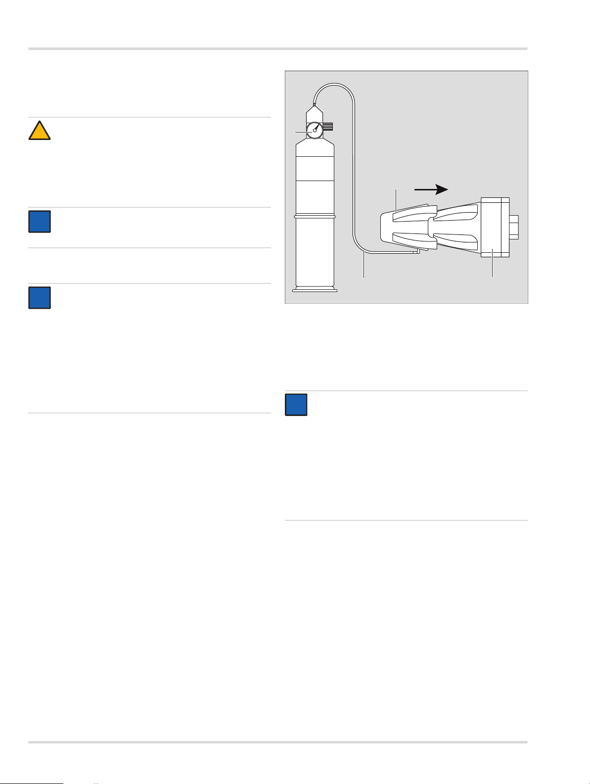
1. Connect the pressure reducer to the calibration gas cylinder.
2. Attach the calibration adapter to the sensor.
3. The gas flow should be between 0.5 and 2.0 l/min.
4. Connect the hose to the calibration adapter.
2
4
1
3
1 Test gas cylinder
2 Pressure reducer
3Hose
4 Calibration adapter
5.1.1 Zero point calibration
NOTICE
i
i
Ambient air can also be used instead of nitrogen or
synthetic air to zero the sensor, provided it is insured
that the ambient air contains no measured gas or any
other gas for which the sensor may exhibit crosssensitivity (see the details in the sensor data sheet).
In this case, neither a gas cylinder nor a calibration
adapter is required for the zero point calibration.
PIR 7000
00433300.eps
For the Polytron 8720 (with PIR 7200 to detect carbon
dioxide), only nitrogen or synthetic air without any CO
content may be used for a zero point calibration.
1. Select Calibration > Zero Calibration and confirm.
The Maintenance signal is transmitted.
The message Apply zero gas is displayed.
2. Connect zero gas (synthetic air or nitrogen) to the sensor.
3. Select Next and confirm.
The current value is displayed.
After the displayed value is stable:
4. Select Calibrate and confirm.
The message Please wait… is displayed.
The actual value is displayed.
14 Dräger Polytron 8700/8720
2
Page 15

Calibration
z Actual value within the permissible range:
{ Select Next and confirm.
{ Shut off the test gas and remove the calibration adapter
from the PIR 7000/7200.
z Actual value outside the permissible range:
{ Select Next and confirm.
{ Wait until the measurement is stable.
5.1.2 Span calibration
1. Select Calibration > Span calibration and confirm.
The Maintenance signal is transmitted.
The values for the calibration gas are displayed, e.g.:
Gas Methane
Unit %LEL
Conc. 50.0
All three paramrters can be changed:
z Select Gas and confirm.
{ Select the desired calibration gas from the list and
confirm.
z Select Unit and confirm.
{ Select the desired unit from the list and confirm.
z Select Conc. and confirm.
{ Set the desired concentration of the calibration gas.
When the settings are correct:
2. Select Next and confirm.
A message such as, e.g. Gas flow to METHANE
is displayed.
3. Connect the calibration gas to the sensor.
4. Select Next and confirm.
The current value is displayed.
After the displayed value is stable:
5. Select Next and confirm.
The message Please wait… is displayed.
The actual value is displayed.
z Actual value within the permissible range:
{ Select Next and confirm.
{ Shut off the test gas and remove the calibration adapter
from the PIR 7000/7200.
z Actual value outside the permissible range:
{ Select Next and confirm.
{ Wait until the measurement is stable.
z A calibration can be aborted at any time.
5.2 Performing Auto Calibration
The device offers the option of an automatically sequenced
calibration. This reduces the number of otherwise manual
interactions with the device. The auto calibration is only
suitable for experienced users, as calibration errors can occur
here as a result of tightened procedures.
NOTICE
i
i
Not all of the available sensors and gases support auto
calibration. If the function is not available, a manual
calibration must be performed.
1. Select Settings > Sensor > Autocal. set. to enable or
disable the function.
2. Supply fresh air or feed nitrogen or compressed air at
a flow rate of 0.5 - 2.0 L/min to the sensor.
WARNING
!
It must be insured that during the zero point calibration,
no measured gas is present in the supplied calibration
gas. Particularly with a fresh air calibration, Dräger
recommends performing a second, independent
measurement. Some sensors may only be calibrated
with synthetic air or nitrogen (observe the relevant
sensor data sheets).
3. Select Calibration > Auto cal. and confirm.
{ Please wait... is displayed and a calibration of the zero
point is performed automatically.
{ After a successful zero point calibration, the span
calibration is started.
{ The calibration gas concentration, the units and, where
appropriate, the calibration gas are displayed and can
be changed.
4. Start the calibration with Next; Back to menu aborts the
calibration.
NOTICE
i
i
After 10 minutes without confirmation, the device
reverts to measurement mode without performing
a calibration.
5. Feed the relevant calibration gas to the sensor at a flow
rate of 0.5 - 2.0 L/min.
{ When the measured value is stable, the device performs
the calibration automatically.
{ After a successful calibration, the measurement and
the message Value OK? are displayed.
6. When the measurement is stable, shut off the calibration
gas and wait until the measurement is below any possible
alarm thresholds again.
z The calibration is performed again with Redo.
z Complete the calibration with Accept value.
The device returns to the measurement mode.
Dräger Polytron 8700/8720 15
Page 16

Menu overview
6 Menu overview
Back to
◄
measure
Information page 17 Instrument page 17
Sensor page 17
Calibration page 14 Data logger page 17
Settings page 18
Zero calibration page 14
Span calibration page 15
Auto CAL page 15
SIL activation page 18
Instrument page 18
Communication page 21
Sensor page 24
Data logger
Datalogr. on/off
Set Datalogger
Clear datalogr
Sample time
Peak/Average
Trigger on/off
Trigger value
Stack/Roll
Warnings
Faults
Device codes
Modules
Last cal. date
Next cal. date
Logger status
Graph
Alarm
Passwords
Date and time
Language
Function key
Device init
SW dongle
Display
HART interface
Analog interface
Profibus address
Auto CAL
Sensortest
Sensor lock
Sensor type
Gas settings
Reset sensor
required!
Cal. interval
Set Sensortest
Fast response
page 17
page 17
page 17
page 17
page 17
page 17
page 17
page 17
page 18
page 20
page 20
page 20
page 20
page 20
page 20
page 20
page 21
page 21
page 23
page 24
page 24
page 23
page 23
page 23
page 23
page 23
page 23
page 23
Alarm on/off
Relay A1
Relay A2
Alarm A1
Alarm A2
Set alarm A1
Set alarm A2
Set fault
Calibration PWD
Settings PWD
Display contrast
Operating mode
Display test
Polling address
Unique identifier
Tag
Dräger REGARD
Fault current
Warning
Warning interval
Warning current
Maintenance signal
Maintenance current
Beamblock on/off
Beambl. current
Analog offset
Set current
Set concentr.
Set fault
Set warning
Set mainten.
Set beamblock
page 18
page 18
page 18
page 18
page 19
page 19
page 19
page 19
page 20
page 20
page 20
page 20
page 21
page 21
page 21
page 21
page 21
page 21
page 21
page 21
page 22
page 22
page 22
page 22
page 22
page 22
page 23
page 23
page 23
page 23
page 23
page 23
16 Dräger Polytron 8700/8720
Page 17

Information menu
OK
7 Information menu
Specific data about the device, the sensor used and the
measured gas are summarized in this menu. The menu can be
accessed without a password. Changes to the data are not
possible.
7.1 Device settings
7.1.1 Displaying warning messages
To display warnings in plain text with warning numbers,
see chapter 9 on page 27.
The symbol is displayed when there is a warning present.
z Select Information > Instrument > Warnings and confirm.
Warnings are displayed in plain text.
If several warnings are present, this is indicated in the upper
right-hand corner of the display, e.g., 1/3 = Screen 1 of 3.
7.1.2 displaying fault messages
To display faults present in plain text with fault numbers,
see chapter 9 on page 27.
The symbol is displayed when there is a fault present.
z Select Information > Instrument > Faults and confirm.
Faults are displayed in plain text.
If several faults are present, this is indicated in the upper
right-hand corner of the display, e.g., 1/2 = Screen 1 of 2.
7.1.3 Displaying device codes
Display of codes for faults/warnings in a numerical table
(hexadecimal).
The symbol is displayed when there is a fault present.
z Select Information > Instrument > Device codes and
confirm.
Faults are displayed as a hexadecimal numerical code in
tabular form. If all the numerical groups are displayed as 00,
there are no faults or warnings present.
7.2 Sensor information
This menu contains the functions for retrieving the calibration
data.
7.2.1 Display last calibration date
Display the date of the last calibration.
z Select Information > Sensor > Last cal. date and confirm.
The date of the last calibration is displayed
7.2.2 Display next calibration date
Display the date of the next calibration.
z Select Information > Sensor > Next cal. date and confirm.
The date when the next calibration of the sensor is due is
displayed.
7.3 Datalogger information (only with
data dongle)
This menu contains the functions for querying the datalogger.
7.3.1 Displaying the datalogger status
z Select Information > Datalogger > Logger status
and confirm.
The current status of the datalogger is displayed: Datalogr. :
on or off (datalogger on or off)
z To switch the datalogger on/off, see chapter 8.5.1 on
page 25.
7.3.2 Displaying a graph of measured values
Show the measurements from the sensor on a 15-minute
time axis.
z Select Information > Datalogger > Graph and confirm.
NOTICE
i
i
The fault code is very helpful for technical support and
should always be stated in full in the event of a fault.
7.1.4 Displaying installed modules
Display of the installed hardware modules.
z Select Information > Instrument > Modules and confirm.
A list of all possible modules is displayed. The installed
modules are identified by a , those not installed by a .
z Mark a module and request detailed information with .
Dräger Polytron 8700/8720 17
Page 18

Settings menu
8 Settings menu
This menu contains all the functions that are required for the
individual configuration of the device.
8.1 Switching SIL lock on or off
NOTICE
i
i
SIL lock is only available for certain sensors (see also
the sensor data sheets or the Dräger Polytron 8X00
Safety Manual).
With this function, the device can be protected against
unauthorized changes to the configuration with a password.
Changing the configuration (e.g., changing the measurement
range from 100 %LEL to 50 %LEL) will cause the device to
display all the safety-relevant parameters to the user once
more before it returns to the measurement mode. The
correctness of the parameters and settings must be confirmed.
1. Select Settings > Instrument > Set SIL.
2. Select the desired state On or Off and confirm.
NOTICE
i
i
When SIL is activated, the device displays all the
important parameters and setting before returning to
measurement mode. Check the parameters and
settings carefully and confirm.
8.2 Device settings
8.2.1 Alarm settings (only with installed relay module)
Alarms issued via relays and LEDs.
CAUTION
!
In the normal state, the relays in the relay module are
energized. That is, the relays change their state if the
power supply is interrupted!
Switching the alarm on or off
1. Select Settings > Instrument > Alarm > Alarm on/off.
2. Select the desired state On or Off and confirm.
CAUTION
!
If the alarm is inactive, the alarm state will not be
issued by the LEDs or the relay interface! A warning
message will be shown on the display!
Configuring Relay A1 or A2
This function is used to define whether the alarm relay is
energized in standard operation or in an alarm state. If the
configuration of the relay is set to "Normally energized", the
corresponding relay contact is closed in the normal case and
drops out in the event of an alarm. This configuration results in
an alarm being triggered in the event of a loss of power to the
transmitter (fail-safe). The fault relay is factory-configured to
"Normally energized" and cannot be changed.
1. Select Settings > Instrument > Alarm > Relay A1 or
Relay A2 and confirm.
2. Select Normal energy supply oder Energy supply
during alarm and confirm.
Configuring Alarm A1 or A2
1. Select Settings > Instrument > Alarm > Alarm A1 or
Alarm A2 and confirm.
2. Select the line for entering the alarm limit and confirm.
3. Set the threshold and confirm.
The setting for the alarm threshold is displayed.
4. Select Next and confirm.
The setting for the alarm direction is displayed.
5. Select Rising or Falling and confirm.
6. Select Next and confirm.
The setting for the alarm direction is displayed.
7. Select Latching or Non Latching and confirm.
8. Select Next and confirm.
The setting for the acknowledgement is displayed.
9. Select Acknowledgeable or NonAcknowledgeabl or
PreAcknowledgeabl and confirm.
10. Select Next and confirm.
The functional relationship between the various settings is
explained in the following table:
Latching and
acknowledgeable
Latching and not
acknowledgeable
Latching and preacknowledgeable
Non-latching and
acknowledgeable
Non-latching and not
acknowledgeable
Non-latching and preacknowledgeable
The alarm must be acknowledged
manually. The alarm can be
acknowledged when the alarm
condition is still present.
The alarm must be acknowledged
manually. The alarm can only be
acknowledged when the alarm
condition is no longer present.
The alarm must be acknowledged
manually. The alarm can be
acknowledged when the alarm
condition is still present but will only
be reset when the alarm condition is
no longer present.
The alarm is acknowledged
automatically when there is no longer
any alarm condition present, or it can
be acknowledged manually.
The alarm is acknowledged
automatically when there is no longer
any alarm condition present.
The alarm cannot be acknowledged
manually.
Corresponds to the alarm behavior
for "Non-latching" and "Not
acknowledgeable".
18 Dräger Polytron 8700/8720
Page 19

Settings menu
Overview of standard alarm settings (for Polytron 8700
with PIR 7000, configured for methane, full scale reading
of 100 %LEL)
A1/Relay 1 A2/Relay 2
Alarm threshold 20 %LEL 40 %LEL
Hysteresis 0 %LEL 0 %LEL
Relay Normally
Relay alarm:
Direction
Latching mode Non-latching Latching
Acknowledgement
mode
The function for setting the A1 hysteresis is opened.
This function permits the setting of a zone within which
a triggered relay maintains its status until the gas concentration
is outside the zone. This function prevents relays from
chattering at an alarm threshold.
Example: A2 at 40 %LEL methane
Maximum possible hysteresis: 3 %LEL
Alarm activation at measured values ≥40 %LEL
Alarm deactivation at measured values ≤37 %LEL (40 %LEL 3 %LEL)
energized
Rising Rising
Acknowledgeable Not
Normally
energized
acknowledgeable
1. Select Settings > Instrument > Alarm > Set Alarm A2
and confirm.
2. Select On or Off and confirm.
When the function is activated, the relay and the interface are
set to the A2 alarm status and the red LED gives double flashes.
Testing Fault status
NOTICE
i
i
When the function Set fault is exited in the menu,
the Polytron 87X0 reverts automatically to measurement
mode.
This function simulates the Fault alarm.
1. Select Settings > Instrument > Alarm > Set fault
and confirm.
2. Select On or Off and confirm.
When the function is activated, the Fault relay and the 4-20 mA
interface are set to the fault current and the yellow LED lights.
11. Select the line for entering the hysteresis and confirm.
12. Set the hysteresis for A1 and confirm.
The hysteresis setting for A1 is displayed.
13. Select Next and confirm.
The settings for A1 are displayed.
14. Select and confirm with Confirm.
The settings for the A1 alarm are now complete.
Testing Alarm A1
NOTICE
i
i
When the function Set Alarm A1 is exited in the menu,
the Polytron 87X0 reverts automatically to measurement
mode.
This function simulates the A1 alarm status.
1. Select Settings > Instrument > Alarm > Set Alarm A1
and confirm.
2. Select On or Off and confirm.
When the function is activated, the relay and the interface are
set to the A1 alarm status and the red LED gives single flashes.
Testing Alarm A2
NOTICE
i
i
When the function Set Alarm A2 is exited in the menu,
the Polytron 87X0 reverts automatically to measurement
mode.
This function simulates the A2 alarm status.
Dräger Polytron 8700/8720 19
Page 20

Settings menu
OK
8.2.2 Changing passwords
The passwords for calibration (zero and span calibrations) and
for the settings (full configuration) can be defined in this menu.
1. Select Settings > Instrument > Passwords > Calibration/
Settings PWD and confirm.
2. Select the line for the password settings and confirm.
3. Set the password and confirm.
The setting for the password is displayed.
4. Select Confirm and confirm.
8.2.3 Setting the date and time
1. Select Settings > Instrument > Date and time and confirm.
2. Select the desired line and confirm in order to switch to the
Change mode.
3. Set each digit and confirm each setting.
4. Select Confirm and confirm.
8.2.4 Changing the display language
1. Select Settings > Instrument > Language and confirm.
2. Select the desired language from the list and confirm.
8.2.5 Configuring the function key
This function is used to assign a predefined function to the
key. The selected function is activated by briefly taping the
key.
8.2.6 Resetting the device to factory settings
The following device parameters are reset to the factory
settings with this function (see chapter 13.3 on page 33).
z Alarm parameters
z Passwords
z Language
z Function key
z HART interface
z Data logger
z Analog interface
z Relay configuration
1. Select Settings > Instrument > Device init. and confirm.
2. Select Confirm and confirm in order to reset the device to
the factory settings.
8.2.7 Deactivating the software dongle
This function allows the SW dongles to be deactivated before
they are removed or in the event of a fault.
A dongle can only be reactivated by switching the power to the
device off and on.
1. Select Settings > Instrument > SW dongle > Dongle
datalogger/Dongle sensortest/Dongle diagnostic and
confirm.
2. Select Deactivate func. and deactivate Dongle datalogger/
Dongle sensortest/Dongle diagnostic with .
1. Select Settings > Instrument > Function key and confirm.
2. Select the desired function and confirm.
z Repeating the confirmation deactivates the selected
function.
z If Bumptest is selected:
The maintenance symbol is shown on the right hand
side of the display and the maintenance signal is output.
Repeating the confirmation ends the bump test and the
device reverts to the normal measurement mode.
z In measurement mode, the selected function can be
activated by briefly pressing .
Selection options:
Graph (only with
data logging)
The measurements from the sensor
are displayed graphically on a time axis
(see chapter 7.3.2 on page 17).
Faults Faults are displayed in plain text
(see chapter 7.1.2 on page 17).
Warnings Warnings are displayed in plain text
(see chapter 7.1.1 on page 17).
Bump test The bump test allows gas to be applied
without an alarm being issued. The
maintenance signal is output on the
4-20 mA output.
Sensor vitality Shows the remaining sensor vitality
(only available for certain sensors).
8.2.8 Display settings
Changing the contrast
1. Select Settings > Instrument > Display > Display contrast
and confirm.
2. Change the contrast and confirm.
Changing the display mode
The display of measured values can be turned on or off with
this function.
1. Select Settings > Instrument > Display > Display mode
and confirm.
2. Select Standard or Non display and confirm.
If "Non display" has been selected, the display shows the start
screen and the symbols.
If the relay option is set and an alarm is triggered, the display
shows the current gas concentration and the red LED flashes,
regardless of the selected display mode.
20 Dräger Polytron 8700/8720
Page 21

Settings menu
Switching the display test on or off
The function of the display and the LEDs is tested with
this function.
1. Select Settings > Instrument > Display > Displaytest
and confirm.
2. Select On or Off and confirm.
When this function is activated, the display is shown inverted
and all the LEDs are lit.
8.3 Communication settings
8.3.1 Settings for the HART interface (only for devices with the optional HART interface)
This group contains the setting functions for the HART interface.
Setting the polling address
The polling address configures the device for analog operation
(4 to 20 mA) or multidrop operation. Analog operation (4 to
20 mA) is activated by setting the polling address to 0.
For multidrop operation the polling address must be
configured to a value between 1 and 15, which will result in the
analog interface being deactivated and set to a constant
current of approx. 1 mA. To allow the control unit to request the
Unique Identifier (unique HART address) with HART command
#0, all the devices on a line must be configured with different
polling addresses. It is advisable to choose a sequence
starting with 1 and incrementing continuously.
This setting corresponds to HART command #6 (Write Polling
Address).
1. Select Settings > Communication > HART interface >
Polling address and confirm.
2. Select the address line for the entry and confirm in order to
switch to the Change mode.
3. Set the polling address and confirm.
4. Select Confirm and confirm.
Displaying the Unique Identifier
This function enables reading of the Unique Identifier (unique
HART address), which has to be known for almost all the
HART addressing commands. However this information is only
required for those systems that are not able to read back the
Unique Identifier using HART command #0 in Short-Frame
Format or HART command #11. The display corresponds to
the address for HART command #0 (Read Unique Identifier) or
#11 (Read Unique Identifier associated with Tag).
z Select Settings > Communication > HART interface >
Unique Identifier and confirm.
The Unique Identifier is displayed.
Changing the measuring point name
The tag can be used to identify special devices. It can contain
up to 8 alphanumeric characters. The tag can also function as
an address for reading the unique identifier from the device
using HART command #11 (Read Unique Identifier Associated
With Tag), even when the polling address is unknown.
This requires that a unique tag has previously been configured.
1. Select Settings > Communication > HART interface >
Tag and confirm.
2. Select the tag line for the entry and confirm.
3. Set the tag and confirm.
4. Select Confirm and confirm.
Selecting Dräger REGARD
This function enables switching between different HART
protocols.
NOTICE
i
i
REGARD SW 2.0 is the standard setting. REGARD
SW 1.4 must be set on REGARD controllers with
SW 1.4.
1. Select Settings > Communication > HART interface >
Dräger REGARD and confirm.
2. Select REGARD SW 2.0 or REGARD SW 1.4 and confirm.
8.3.2 Settings for the analog interface
The test and setting functions for the analog interface are
summarized in this menu.
Setting the fault current
This function is used to define the current for the fault signal on
the analog interface.
1. Select Settings > Communication > Analog interface >
Fault current and confirm.
2. Select the fault current line and confirm.
3. Set the currrent and confirm.
4. Select Confirm and confirm.
Switching the warning signal on or off
This function is used to switch the warning signal on the analog
interface on and off. If an existing warning is to be output over
the analog interface, the warning signal must be turned on.
During a warning, the current on the analog interface is
switched to the "Warning" status for one second.
The measurement is transmitted for the rest of the time.
The interval between warning signals and the analog signal
phase can be customized.
To switch the warning signal on or off:
1. Select Settings > Communication > Analog interface >
Warning and confirm.
2. Select On or Off and confirm.
Setting the warning interval
This function is used to set the interval between the warning
signals and the analog interface.
1. Select Settings > Communication > Analog interface >
Warning interval and confirm.
2. Select line T1 for the entry and confirm.
3. Set the time and confirm.
The setting for Time T1 is displayed.
4. Select Next and confirm.
5. Select line T2 for the entry and confirm.
6. Set the time and confirm each setting.
The setting for Time T2 is displayed.
7. Select Confirm and confirm.
Dräger Polytron 8700/8720 21
Page 22

Settings menu
Value
0633300.eps
t
[s]
1,1
[mA]
0,7
5
3
[mA]
20
4
3
T
T
2
1
t
[s]
0533300.eps
Setting the warning current
This function is used to define the current for the warning
signal on the analog interface.
1. Select Settings > Communication > Analog interface >
Warning current and confirm.
2. Select the current line for the entry and confirm.
3. Set the currrent and confirm.
The setting for the warning current is displayed.
4. Select Confirm and confirm.
Changing the maintenance signal type
This function is defines the type of signal used on the analog
interface for the maintenance signal.
1. Select Settings > Communication > Analog interface >
Maint. signal and confirm.
2. Select static or dynamic signal type and bestätigen.
NOTICE
i
i
The static signal type is a constant current. The current
can be configured.
The dynamic signal type is a square wave signal with
the following characteristics:
Setting the maintenance current
This function is used to define the current for the maintenance
signal on the analog interface.
1. Select Settings > Communication > Analog interface >
Maint. current and confirm.
2. Select the current line for the entry and confirm.
3. Set the currrent and confirm.
The setting for the maintenance current is displayed.
4. Select Confirm and confirm.
NOTICE
i
i
The maintenance current can only be set if the
maintenance signal has been set to static. This function
is not available otherwise.
Switching Beam Block on or off (for PIR 7000/7200 only)
If the Beam Block signal is enabled and the optical surfaces of
the PIR 7000 or PIR 7200 are dirty, a Beam Block signal will be
output over the analog output of the transmitter. In the case of
a high and potentially dangerous gas concentration of more
than 15 % LEL (PIR 7000) or 15 % of the full-scale reading
(PIR7200), the device will switch back to the normal measuring
mode. If the contamination on the surfaces increases and
correct measurement is not possible, the device transmits
a fault signal.
1. Select Settings > Communication > Analog interface >
Beamblock on/off and confirm.
2. Select On or Off and confirm.
Setting the beam block current (for PIR 7000/7200 only)
This function is used to define the current for the beam block
signal on the analog interface.
1. Select Settings > Communication > Analog interface >
Beambl. current and confirm.
2. Select the current line for the entry and confirm.
3. Set the currrent and confirm.
The setting for the beam block current is displayed.
4. Select Confirm and confirm.
Setting the 4-20 mA offset
This function can be used to set an adjustable offset current on
the analog interface. The offset is constant over the entire
range of the output signal.
1. Select Settings > Communication > Analog interface >
Analog offset and confirm.
2. Select the current line for the entry (max. range: -0.2 to
1.5 mA) and confirm.
3. Set the currrent and confirm.
The setting for the 4-20 mA offset is displayed.
4. Select Confirm and confirm.
22 Dräger Polytron 8700/8720
Page 23

Settings menu
Test functions for the analog interface
NOTICE
i
i
Alarms in the central controller may be triggered by
these functions! If necessary, the alarms in the central
controller must be disabled beforehand.
Setting current signals
Using this function, various currents in the range from 0 to
22 mA can be set on the analog interface.
1. Select Settings > Communication > Analog interface >
Set current and confirm.
2. If the alarm in the control unit is disabled, confirm the
message Inhibit all alarms.
3. Select the current line for the entry and confirm.
4. Set the currrent and confirm.
The setting for the current is displayed.
5. Select Next and confirm.
6. Select Set current out or Current off and confirm.
7. Select Next and confirm. The function is terminated.
8. After the alarm settings in the control unit have been reenabled, confirm the Enable all alarms message.
Setting the concentration
This function is used to simulate various concentrations in the
range between 0 and 100 % of the selected unit of measure.
The current output is set to correspond to the selected
concentration.
1. Select Settings > Communication > Analog interface >
Set concentr. and confirm.
2. If the alarm in the control unit is disabled, confirm the
message Inhibit all alarms.
3. Select the concentration line for the entry and confirm.
4. Set the concentration and confirm.
The setting for the concentration is displayed.
5. Select Next and confirm.
6. Select Set concentr. or Concentration of and activate.
7. Select Next and confirm. The function is terminated.
8. After the alarm settings in the control unit have been reenabled, confirm the Enable all alarms message.
Testing the maintenance signal
This function is used to set the analog interface to the
maintenance signal.
1. Select Settings > Communication > Analog interface >
Set mainten. and confirm.
Select On or Off and confirm.
2.
{ The current for the maintenance signal will be
transmitted on the analog interface.
Testing the beam block signal (for PIR 7000/7200 only)
This function is used to set the analog interface to the beam
block signal.
1. Select Settings > Communication > Analog interface >
Set beamblock and confirm.
2. Select On or Off and confirm.
{ The current for the beam block signal will be
transmitted on the analog interface.
8.3.3 Profibus address
Not yet active - for future functions.
Testing the Fault signal
This function is used to set the analog interface to the
fault current.
1. Select Settings > Communication > Analog interface >
Set fault and confirm.
2. Select On or Off and confirm.
The current for the Fault signal will be transmitted on the
analog interface.
Testing the warning signal
This function is used to set the analog interface to the
warning signal.
1. Select Settings > Communication > Analog interface >
Set warning and confirm.
2. Select On or Off and confirm.
The current for the warning signal will be transmitted on the
analog interface.
Dräger Polytron 8700/8720 23
Page 24

Settings menu
8.4 Sensor settings
8.4.1 Switching Auto CAL on or off
NOTICE
i
i
The auto-calibration from the Calibration menu is only
available if this function is enabled.
1. Select Settings > Sensor > Set auto calibration and
confirm.
2. Select On or Off and confirm.
8.4.2 Sensor testsettings
NOTICE
i
i
The sensor test settings are only available for certain
sensors.
The setting functions for the sensor self test are summarized
in this group of functions.
8.4.3 Switching the sensor test on or off (for EC
When the sensor self test is enabled, the device continuously
checks the sensor to insure reliable functioning. If the sensor
does not pass the self test, an appropriate warning or fault
indication is issued.
1. Select Settings > Sensor > Sensor test and confirm.
2. Select On or Off and confirm.
8.4.4 Switching the sensor lock on or off (for EC sensors
This function is used to activate or deactivate the sensor
interlock.
1. Select Settings > Sensor > Sensor lock and confirm.
2. Select On or Off and confirm.
sensors only)
and PIR 7000/7200 only)
Standard
setting
On = The device will only accept a new sensor if
Off = The device will also accept other sensor
=Off
the Part Number (= Dräger Order Number),
and hence the sensor type, is identical to
that of the previous sensor.
types and with thus adopt the default
settings for the sensor, i.e., in this case the
configuration of the device will be altered.
8.4.6 Changing the gas settings
Settings for gas type, measuring range and measurement
units can be made in this menu.
1. Select Settings > Sensor > Gas setting and confirm.
2. Select the measured gas from the list and confirm.
The measurement units display will be shown.
3. Select the measurement units and confirm.
The full scale reading display will be shown.
4. Set the full scale reading and confirm.
The setting for the full scale reading is displayed.
5. Select Next and confirm.
an overview of the new gas settings is displayed.
z Return to the previous view with Previous or confirm the
settings with Confirm.
Information about the measured gas
If the PIR 7000/7200 sensor is used, the measured gas can be
selected from many different gases. These substances are
already stored in the PIR 7000/7200 as library substances.
Selecting a library function has the following effects:
z The name of the library substance is shown in the display.
z The selected substance is automatically selected as the
calibration gas.
z The output signal of the PIR 7000/7200 is linearized and
temperature compensated for this substance.
z All other necessary parameters for this substance such as,
e.g., detection limit or measuring ranges are updated and
adopted for the Polytron 8000.
z List of measured gases: see chapter 12 on page 30.
Information about measurement units
The Polytron 8000 represents the measured value in various
optional units. The following are available:
z ppb z L/m3
z ppm z mL/L
z vol.% z mL/m3
z %LEL z uL/L
z %LIE z uL/m3
z %UEG
The Polytron 8000 automatically calculates the correct value.
Information about the category
NOTICE
i
i
This selection is only displayed if %LEL, %UEG or
%LIE was selected for the units.
8.4.5 Setting the sensor type (for DD sensors only)
This function is used to set the sensor type.
1. Select Settings > Sensor > Sensor type and confirm.
2. Select sensor type PIR 7000 (for all PIR 7000/7200
variants) or PIR 3000 and confirm.
24 Dräger Polytron 8700/8720
If the units %UEG, %LEL or %LIE are selected, the device
offers various fixed categories based on the standards of
NIOSH, IEC or PTB.
With Custom specific it is possible to enter an individual
conversion of a volume concentration [vol.%] into % of the
Lower Explosive Limit [%LEL] The maximum selectable limits
are approx +-25 % of the NIOSH category applicable to the
particular gas.
Page 25

Settings menu
Example:
NIOSH Category, measured gas: Methane 100 %LEL
corresponds to 5.0 vol.%
Customer specific: Measured gas: methane 100 %LEL
corresponds to 4.7 vol.% methane
Information about the 20 mA measuring range
The full scale reading can be set with this function. At the full
scale reading set, the device outputs 20 mA on the 4-20 mA
interface.
8.4.7 Resetting the sensor to factory settings
This function resets all the sensor parameters to the factory
default settings (see chapter 13.3 on page 33).
1. Select Settings > Sensor > Reset sensor required! and
confirm.
2. Select Confirm and confirm.
8.4.8 Setting the calibration interval
NOTICE
i
i
The calibration interval can be set between 0 and
720 days.
1. Select Settings > Sensor > Calibration interval
and confirm.
2. Set the calibration interval and confirm.
8.4.9 Sensor test
NOTICE
i
i
On means that the PIR 7000/7200 is in the "Fast
response" mode. Off means that the PIR 7000/7200 is
in the "Normal response" mode.
8.5 Datalogger settings (only with data dongle)
NOTICE
i
i
The functions are only available if the Polytron 8000 is
fitted with the data dongle (Order Number 83 17 618),
see chapter 3.10 on page 10.
The datalogger has a storage capacity of approx.
3000 measurements. At a sampling interval of 1 minute, this
would allow monitoring for approx. 50 hours. The monitoring
time can be significantly increased if the Trigger function is
enabled.
The results in the datalogger can only be evaluated with the
PolySoft 8000 PC software. An evaluation of the datalogger
contents over the last 15 minutes is available in the menu
under Information > Datalogger > Graph (see chapter 7.3.2
on page 17).
8.5.1 Switching the datalogger on or off
1. Select Settings > Datalogger > Datalogr. on/off and
confirm.
2. Select On or Off and confirm.
NOTICE
i
i
This function is not available when the PIR 7000/7200
sensor is used.
8.4.10 Switching Fast Response on or off (for PIR 7000/ 7200 only)
CAUTION
!
Activating the Fast response function increases the
repeatability error by a factor of 2. A complete
calibration must always be performed after changing
the response.
In the default configuration, the device has a minimum
response time of 4 seconds. The device can be converted to
a fast response with this function. This can be expedient when
supplying the measured gas via a pump or when operating in
pipes, where rapid monitoring of the change in the measured
gas concentration is desired (see also the Technical Handbook
for the PIR 7000/7200).
1. Select Settings > Sensor > Fast response and confirm.
2. Select On or Off and confirm.
8.5.2 Setting up the datalogger
Setting the sampling interval
1. Select Settings > Datalogger > Datalogr. on/off >
Sample time and confirm.
2. Select the sample time and confirm.
Setting peak/average
1. Select Settings > Datalogger > Set datalogger > Peak/
average and confirm.
2. Select the desired function and confirm.
Peak value The measured maximum (for O2, the minimum
value) value of the concentration within the
selected sampling interval is stored.
Average The average value of all the concentrations
measured within the selected sampling time
is stored.
Dräger Polytron 8700/8720 25
Page 26

Settings menu
Switching the trigger on or off
1. Select Settings > Datalogger > Set datalogger > Trigger
on/off and confirm.
2. Select On or Off and confirm.
On Concentrations will only be stored if they
exceed (relative to the last stored value)
a threshold set under Trigger Value.
Off The measurements made within the set
Setting the trigger threshold
The trigger threshold is specified as a percentage of the full
scale reading.
Example: A trigger threshold of 2 % is entered for a full scale
reading of 500 ppm. Consequently the datalogger will only
store measurements if they deviate (relative to the last stored
value) by 10 ppm.
1. Select Settings > Datalogger > Datalogr. on/off >
Trigger value and confirm.
2. Set the trigger value and confirm.
Setting the storage mode
1. Select Settings > Datalogger > Set Datalogger > Stack/
Roll and confirm.
2. Select the desired condition and confirm
sampling time are always stored.
Overwrite When the capacity of the datalogger is
used up, the older data will be overwritten.
Hold When the capacity of the datalogger is
8.5.3 Clearing the datalogger
1. Select Settings > Datalogger > Clear Datalogr.
and confirm.
2. To clear the datalogger, select Confirm and confirm.
used up, no more data can be stored.
An appropriate warning is issued.
26 Dräger Polytron 8700/8720
Page 27

9 Troubleshooting
9.1 Fault reference:
Fault number Cause Remedy
#001
#003
#004
#005
#011 - #014
#020 - #024
#043
#060
#067
#002
#025 - #027
#030 - #034
#041
#042
#044
#050
#052
#081
#085
Serious device fault, various causes.
Serious data error in the device,
various causes.
Have the device checked by DrägerService
Reset the device to factory settings (see chapter 8.2.6 on
page 20).
If this fault occurs again:
Have the device checked by DrägerService.
Troubleshooting
®1
.
#10 4-20 mA interface cable not connected. Disconnect the powwer supply, connect the 4-20 mA interface
and reconnect the power supply.
#051
#054
#055 Faulty span calibration was performed. Perform new span calibration (see chapter 5.1.2 on page 15).
#064
#071
#083 PIR 7000/7200 optics dirty. Clean PIR 7000/7200 optics.
#086 Supply voltage outside range. Check supply voltage.
#087 Device fault, 4 - 20 mA PIR 7000/7200. Check 4-20 mA connection on PIR 7000/7200.
#090 Sensor lock function is activated. A sensor
#094
#095
#096 Differing SIL password on PIR 7000/7200. Enter the password again.
1 DrägerService® is a registered trademark of Dräger.
Faulty zero-point. Perform zero-point calibration (see chapter 5.1.1 on page 14).
Communications fault. Check contact with PIR 7000/7200.
Disable the sensor lock function (see chapter 8.4.4 on
with a different part number than was
previously configured has been used.
Data error in the device. Reset the sensor to factory settings (see chapter 8.4.7 on
page 24) or use a new sensor with the same part number.
page 25).
If this fault occurs again:
Have the device checked by DrägerService.
Dräger Polytron 8700/8720 27
Page 28

Troubleshooting
9.2 Warning reference
Warning
number
#101 Datalogger in Stack mode is 100 % full and is
#102 Datalogger in Stack mode is 90 % full. Read out the data as soon as possible, clear the datalogger and
#103
#106
#104 No valid date or time set. Set time and date (see chapter 8.2.3 on page 20).
#107 Battery almost used up. Have the device checked by DrägerService.
#110
#111
#112
#113 Alarms disabled. Enable alarms (see chapter 8.2.1 on page 18).
#164
#165
#167
#170
#171 Increased zero-point offset. Perform zero-point calibration (see chapter 5.1.1 on page 14).
#172 PIR 7000/7200 optics dirty. Clean PIR 7000/7200 optics.
#182 Autocalibration not possible with PIR 7200. Perform new zero-point and span calibration (see chapter 5.1.2
Cause Remedy
Read out the data, clear the datalogger and start again.
not logging any more data.
start again.
Data error in the device. Functions such as
the datalogger or dongle functions may no
longer be available.
SW dongle has been removed without
logging out.
Sensor warm-up phase has not ended yet.
Increased measurement error must be
expected.
Calibration interval expired. Recalibrate the device (see chapter 5 on page 14).
Reset the device to factory settings (see chapter 8.2.6 on
page 20).
If this fault occurs again:
Have the device checked by DrägerService.
Disable SW dongle (see chapter 8.2.7 on page 20).
Wait until the sensor has warmed up.
on page 15).
28 Dräger Polytron 8700/8720
Page 29
Maintenance
10 Maintenance
10.1 Maintenance intervals
10.1.1 During commissioning
z Check calibration.
z Check signal transmission to controller and triggering of
alarms.
10.1.2 Every 6 months
z Inspection by trained service personnel.
The inspection intervals must be established in each individual
case and shortened if necessary, depending on technical
safety considerations, engineering conditions, and the
technical requirements of the equipment.
Contact DrägerService if you wish to take out a service
contract and have any repairs carried out.
10.1.3 As required
z Change the sensor, see chapter 10.2 on page 29.
10.2 Changing the sensor
WARNING
!
As a matter of principle, always check a newly installed
sensor with measured gas to insure correct operation.
CAUTION
!
When the sensor is changed, all settings and
parameters must be checked for correctness.
NOTICE
i
i
The analog interface of the PIR 7X00 must be
configured to the following values (PIR 7x00 factory
settings):
Maintenance signal: 3.0 mA
Alt. maintenance signal: Off
Beam block warning: 2 mA (inactive)
Alternating warning signal: Off
Fault signal: 1 mA
The sensor is changed as follows:
1. Switch off the power to the unit or declassify the area
according to the local regulations.
2. Release the retaining screw and unscrew the housing
cover from the device.
3. Lift the handle and remove the enclosure with the main
electronics.
4. Disconnect the sensor cable.
5. Unscrew the PIR 7000/7200.
6. Pass the sensor cable through the threaded connection in
the housing.
7. Screw in the PIR 7000/7200.
WARNING
!
Five threads must be engaged to insure explosion
protection.
8. Plug the sensor cable into the socket.
9. Re-fit the sensor electronics and enclosure.
10. Screw the housing cover on again and tighten the retaining
screw.
11. Switch on the power to the device.
12. If necessary, switch off SIL activation (see chapter 8.1 on
page 18).
13. Calibrate the device if necessary (see chapter 5 on
page 14).
14. If required, switch on SIL activation (see chapter 8.1 on
page 18).
10.3 Changing the main electronics
1. Switch off the power to the unit or declassify the area
according to the local regulations.
2. Release the retaining screw and unscrew the housing
cover from the device.
3. Lift the handle and remove the enclosure with the main
electronics.
4. Remove the protective caps for the connectors.
5. Unscrew the connector locking ring for the power supply
and relay and withdraw the connector.
6. Change the main electronics.
7. Plug the sensor cable and the connector for the power
supply and relay into the corresponding sockets and screw
them tight.
8. Re-fit the dust caps for the connectors.
9. Re-fit the sensor electronics and enclosure.
10. Screw the housing cover on again and tighten the retaining
screw.
11. Switch on the power to the device.
12. Check and adjust the configuration as required.
13. Calibrate the device if necessary (see chapter 5 on page 14).
11 Disposal
Disposal of electrical and electronic equipment:
EU-wide regulations governing the disposal of
electric and electronic appliances which have been
defined in the EU Directive 2002/96/EC and in
national laws have been effective from August 2005
and apply to this device. Common household
appliances can be disposed of using special
collecting and recycling facilities. However, as this
device has not been registered for household usage,
it must not be disposed of through these means.
The device can be returned to your national Dräger
Safety Sales Organization for disposal. Please do not
hesitate to contact the above if you have any further
questions on this issue.
Dräger Polytron 8700/8720 29
Page 30

Substances in the gas library (PIR 7000)
12 Substances in the gas library (PIR 7000)
NOTICE
i
i
The gas code is an internal Dräger designation. Code 001, for example, is assigned to the gas methane. Any change to
the gas to be measured will result in a change to the basic settings for the Polytron 8000. Dräger recommends checking
all settings and configurations.
12.1 Polytron 8700 Type 334
Substance CAS No. Gas Code
Acetaldehyde 75-7-0 402
Acetone 67-64-1 453
Allyl chloride 107-05-1 723
Benzene 71-43-2 260
1,3-Butadiene 106-99-0 172
n-Butane 106-97-8 104
i-Butane 75-28-5 114
1-Butene 106-98-9 154
i-Butene 115-11-7 164
2-Butoxyethanol (n-Butyl glycol) 111-76-2 384
n-Butyl acetate 123-86-4 554
n-Butyl acrylate 141-32-2 584
Chlorobenzene 108-90-7 280
1-Chloro-1,1-difluoroethane
(R 142b)
Cyclohexanone 108-94-1 496
1,2-Dichloroethane 107-06-2 732
Dichloromethane 75-09-2 730
1,2-Dichloropropane 78-87-5 734
1,3-Dichloro-1-propene 542-75-6 744
Diethyl ether 60-29-7 354
Dimethyl ether 115-10-6 352
Epichlorohydrin 106-89-8 820
Ethane 74-84-0 102
Ethanol 64-17-5 302
1-Ethoxypropan-2-ol 1569-02-4 392
Ethyl acetate 141-78-6 552
Ethylene 74-85-1 003
Ethylene oxide 75-21-8 822
n-Hexane 110-54-3 106
1-Hexene 592-41-61 156
Methane 74-82-8 001
Methanol 67-56-1 301
1-Methoxypropan-2-ol 107-98-2 391
2-Methoxy-1-methyl ethyl acetate 108-65-6 570
75-68-3 783
Substance CAS No. Gas Code
Methyl acrylate 96-33-3 581
Methyl tert-butyl ether 1634-04-4 355
Methyl isobutyl ketone 108-10-1 476
Methyl chloride 74-87-3 701
Ethyl methyl ketone 78-93-3 454
n-Nonane 111-84-2 109
n-Octane 111-65-9 108
n-Pentane 109-66-0 105
1-Pentene 109-67-1 155
Propane 74-98-6 002
Isopropanol 67-63-0 313
Propylene 115-07-1 153
Propylene oxide 75-56-9 823
Styrene 100-42-5 270
Toluene 108-88-3 261
o-Xylol (1,2-Dimethyl benzene) 95-47-6 265
The current gas library can be viewed at www.draeger.com.
30 Dräger Polytron 8700/8720
Page 31
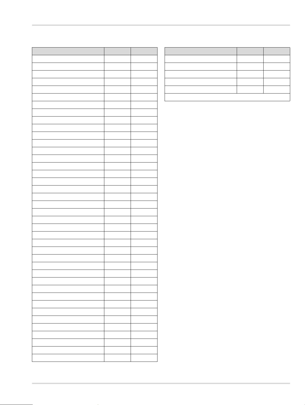
12.2 Polytron 8700 Type 340
Substances in the gas library (PIR 7000)
Substance CAS No. Gas Code
Acetaldehyde 75-7-0 402
Acetone 67-64-1 453
Allyl chloride 107-05-1 723
n-Butane 106-97-8 104
i-Butane 75-28-5 114
1-Butene 106-98-9 154
i-Butene 115-11-7 164
2-Butoxyethanol (n-Butyl glycol) 111-76-2 384
n-Butyl acetate 123-86-4 554
n-Butyl acrylate 141-32-2 584
Cyclohexane 110-82-7 186
Cyclohexanone 108-94-1 496
1,2-Dichloroethane 107-06-2 732
Dichloromethane 75-09-2 730
1,2-Dichloropropane 78-87-5 734
1,3-Dichloro-1-propene 542-75-6 744
Diethyl ether 60-29-7 354
Dimethyl ether 115-10-6 352
Epichlorohydrin 106-89-8 820
Ethane 74-84-0 102
Ethanol 64-17-5 302
1-Ethoxypropan-2-ol 1569-02-4 392
Ethyl acetate 141-78-6 552
Ethylene oxide 75-21-8 822
n-Hexane 110-54-3 106
1-Hexene 592-41-61 156
Methane 74-82-8 001
Methanol 67-56-1 301
1-Methoxypropan-2-ol 107-98-2 391
2-Methoxy-1-methyl ethyl acetate 108-65-6 570
Methyl acrylate 96-33-3 581
Methyl tert-butyl ether 1634-04-4 355
Methyl isobutyl ketone 108-10-1 476
Methyl chloride 74-87-3 701
Ethyl methyl ketone 78-93-3 454
n-Nonane 111-84-2 109
n-Octane 111-65-9 108
n-Pentane 109-66-0 105
1-Pentene 109-67-1 155
Propane 74-98-6 002
Substance CAS No. Gas Code
Isopropanol 67-63-0 313
Propylene 115-07-1 153
Propylene oxide 75-56-9 823
Toluene 108-88-3 261
o-Xylol (1,2-Dimethyl benzene) 95-47-6 265
The current gas library can be viewed at www.draeger.com.
Dräger Polytron 8700/8720 31
Page 32

Technical data
13 Technical data
CAUTION
!
Specifications and restrictions in the Instructions for Use and/or data sheets for the sensors used must be observed.
For SIL applications the Dräger Polytron 8X00 Safety Manual must be observed.
The measuring range and performance characteristics are dependent on the sensor installed, see the Instructions for
Use and/or data sheets for the sensors used.
Signal transmission to the central controller
Analog
Output current 4 mA to 20 mA
Drift below zero-point 3.8 mA to 4 mA
Measuring range exceeded 20 mA to 20.5 mA
Device malfunction ≤1.2 mA
Fault on analog output >21 mA
Maintenance signal 3.4 mA constant signal or 1 Hz modulation between 3 and 5 mA
Supply voltage
Operating voltage 3-wire shielded cable, 24 V DC (10 to 30) V DC
Inrush current 2.3 A for 2 ms at 24 V DC, 10 Ω conductor resistance
(selectable)
Operating current (max.) 330 mA at 24 V DC, no relay, sensor not remote
350 mA at 24 V DC, with relay, remote sensor
Relay design (optional) SPDT, 5 A at 230 V AC, 5 A at 30 V DC, resistive load
For safety-related applications (SIL2), the maximum contact rating is
reduced (see also the Dräger Polytron 8X00 Safety Manual).
Housing NEMA 4X
Protection Class IP 65/66/67
Dimensions (LxWxD)
Without e-Box approx. 150 x 290 x 130 mm (5.9" x 11.4" x 5.1")
With e-Box approx. 180 x 300 x 190 mm (7.1" x 11.8" x 7.4")
Mounting spacer (diameter x D) 150 x 25 mm (5.9” x 1”)
Weight
Without e-Box, aluminum approx. 3.9 kg (8.5 lbs.)
Without e-Box, stainless steel 316 approx. 5.7 kg (12.6 lbs.)
With e-Box, aluminum approx. 5.2 kg (11.5 lbs.)
With e-Box, stainless steel 316 approx. 7.1 kg (15.6 lbs.)
Display Resolution 128 x 64, back-lit
Environmental conditions Specifications for the sensor: see sensor data sheet
Pressure 700 to 1300 hPa (20.7 to 38.4 in. Hg)
Humidity 0 to 100 % R. H., non-condensing
Temperature
without relay
with relay
-40 to +77 °C (-40 to +170 °F)
-40 to +70 °C (-40 to +158 °F)
Environmental influences See respective sensor data sheets.
32 Dräger Polytron 8700/8720
Page 33

Technical data
13.1 Torques
(The torques are valid for the aluminum and stainless steel
316 variants)
Part Torque Lb. In. Torque Nm
Housing cover min. 266 min. 30
Sensors min. 266 min. 30
Blanking plugs min. 266 min. 30
Cable entry min. 443 min. 50
Device to e-Box 71 8
13.2 Tightening torque and cable size for field wiring terminals
Electronic
Torque Lb. In. Cable size in AWG Cable size in mm
All field wiring
terminals
4.4–7.0
(0.5–0.8 Nm)
If an optional e-Box is being used, fasten the device securely
to the e-Box with 4 screws and a tightening torque of 8 Nm.
20–12 0.5–2.5
13.3 Factory settings
13.3.1 Unalterable settings
Fault Meaning
Fault relay / wired
in e-Box
Yellow Fault LED Lights when a fault is present
Red Alarm LED Gives single flashes when an A1 alarm
energized / NO
(see chapter 9 on page 27).
is present.
Gives double flashes when an A2 alarm
is present.
If an alarm is configured as
acknowledgeable and the alarm is
acknowledged, the LED lights.
Alarm hierarchy: A2 has a higher priority
for the LED than A1. However the A1 and
A2 relays operate independently of one
another, i.e. if A1 is acknowledgeable and
A2 is not and the gas concentration is so
high that A1 and A2 are triggered, an
acknowledgement results in the A1 relay
dropping out. However the red LED
continues to give double flashes as long
as the A2 condition exists.
13.3.2 Alterable settings for the Polytron 8700
Standard setting
Menu Polytron
8700 Type
334
Calibration
gas type
Calibration
gas units
Calibration gas
concentration
A1 Alarm 20 %LEL 20 %LEL 1 vol.%
A2 Alarm 40 %LEL 40 %LEL 2 vol.%
A1 Relay alarm:
Direction
A2 Relay Alarm:
2
Direction
A1 latching mode Non-latching Non-latching Non-latching
A2 latching mode Latching Latching Latching
A1 Acknowledge-
ment mode
A2 Acknowledge-
ment mode
A1 enrg / wired in
e-Box
A2 enrg / wired in
e-Box
LEL type NIOSH NIOSH ----
Measured gas Methane Propane CO
Measured
gas units
FSD Set 100 100 5
Password 0000 0000 0000
PIR Lock Off Off Off
SIL password _ _ _2 _ _ _2 _ _ _2
SIL status Off Off Off
Language English English English
Fault current 1.2 mA 1.2 mA 1.2 mA
Warning current 3.0 mA 3.0 mA 3.0 mA
Maintenance
current
Beam block Off Off Off
HART address 0 0 0
Auto-cal. Off Off Off
Calibration
interval
Response Normal Normal Normal
Function key Faults Faults Faults
Methane Propane CO
vol.% vol.% vol.%
2.5 0.75 4.0
Rising Rising Rising
Rising Rising Rising
Acknowledgeable
Not acknowl-
edgeable
Energized / NOEnergized / NOEnergized /
Energized / NOEnergized / NOEnergized /
%UEG %LEL vol.%
3.4 mA 3.4 mA 3.4 mA
360 360 360
Polytron
8700 Type
340
Acknowledgeable
Not acknowl-
edgeable
Polytron
8720
2
Acknowledgeable
Not acknowl-
edgeable
NO
NO
2
Dräger Polytron 8700/8720 33
Page 34

Order list
14 Order list
14.1 Dräger Polytron 8700 Type 334
Name and description
Dräger Polytron 8700 334 d A 4-20/HART 45 44 601
Dräger Polytron 8700 334 d A 4-20/HART Relay 45 44 602
Dräger Polytron 8700 334 d S 4-20/HART 45 44 610
Dräger Polytron 8700 334 d S 4-20/HART Relay 45 44 611
Dräger Polytron 8700 334 e A 4-20/HART 45 44 619
Dräger Polytron 8700 334 e A 4-20/HART Relay 45 44 620
Dräger Polytron 8700 334 e S 4-20/HART 45 44 628
Dräger Polytron 8700 334 e S 4-20/HART Relay 45 44 629
Dräger Polytron 8700 Remote 334 e A 4-20/HART 45 44 673
Dräger Polytron 8700 Remote 334 e A 4-20/
HART Relay
Dräger Polytron 8700 Remote 334 e S 4-20/HART 45 44 682
Dräger Polytron 8700 Remote 334 e S 4-20/
HART Relay
Order
Number
45 44 674
45 44 683
14.2 Dräger Polytron 8700 Type 340
Name and description
Dräger Polytron 8700 340 d A 4-20/HART 45 44 637
Dräger Polytron 8700 340 d A 4-20/HART Relay 45 44 638
Dräger Polytron 8700 340 d S 4-20/HART 45 44 646
Dräger Polytron 8700 340 d S 4-20/HART Relay 45 44 647
Dräger Polytron 8700 340 e A 4-20/HART 45 44 655
Dräger Polytron 8700 340 e A 4-20/HART Relay 45 44 656
Dräger Polytron 8700 340 e S 4-20/HART 45 44 664
Dräger Polytron 8700 340 e S 4-20/HART Relay 45 44 665
Dräger Polytron 8700 Remote 340 e A 4-20/HART 45 44 691
Dräger Polytron 8700 Remote 340 e A 4-20/
HART Relay
Dräger Polytron 8700 Remote 340 e S 4-20/HART 45 44 700
Dräger Polytron 8700 Remote 340 e S 4-20/
HART Relay
Order
Number
45 44 692
45 44 701
14.3 Dräger Polytron 8720
Name and description
Dräger Polytron 8720 d A 4-20/HART 45 44 709
Dräger Polytron 8720 d A 4-20/HART Relay 45 44 710
Dräger Polytron 8720 d S 4-20/HART 45 44 718
Dräger Polytron 8720 d S 4-20/HART Relay 45 44 719
Dräger Polytron 8720 e A 4-20/HART 45 44 727
Dräger Polytron 8720 e A 4-20/HART Relay 45 44 728
Dräger Polytron 8720 e S 4-20/HART 45 44 736
Dräger Polytron 8720 e S 4-20/HART Relay 45 44 737
Dräger Polytron 8720 Re e A 4-20/HART 45 44 745
Dräger Polytron 8720 Re e A 4-20/HART Relay 45 44 746
Dräger Polytron 8720 Re e S 4-20/HART 45 44 754
Dräger Polytron 8720 Re e S 4-20/
HART Relay
Order
Number
45 44 755
14.4 Sensors for remote versions
NOTICE
i
i
The sensors are not included with the remote versions.
Name and description
For Polytron 8700 Type 334 Re e:
Dräger PIR 7000 Type 334 (M25) cpl. set
Connection thread M25 x 1.5
For Polytron 8700 Type 340 Re e:
Dräger PIR 7000 Type
Connection thread M25 x 1.5
For Polytron 8720 Type 340 Re e:
Dräger PIR 7200 (M25) HART® cpl. set
Connection thread M25 x 1.5
®
HART
interface
1 The complete set contains an Ex e junction box, a splash guard,
a status indicator and a mounting kit, already pre-assembled.
340
(M25)
1
1
Order
Number
68 11 825
68 11 819
68 12 290
34 Dräger Polytron 8700/8720
Page 35

Order list
14.5 Replacement sensors (except for remote versions)
Name and description
Dräger PIR 7000 Type 334 (NPT)
Connection thread 3/4" NPT
Dräger PIR 7000 Type
Connection thread 3/4" NPT
Dräger PIR 7200 (NPT) HART
Connection thread 3/4" NPT / HART
340
(NPT)
®
interface
Order
Number
68 11 822
68 11 832
68 11 572
14.6 Accessories for Polytron 8700/8720
Name and description
D-Junction Box, aluminum 45 44 099
D-Junction Box, stainless steel 316 45 44 098
Duct mounting kit (PIR 7000) Polytron 5000/
8000
Pipe mounting kit, Polytron 5000/8000 45 44 198
IR connection kit, 5000/8000 45 44 197
Magnetic wand with key chain 45 44 101
Order
Number
68 12 300
14.7 Replacement parts
Description
Bucket Polytron 87X0 4-20/HART, SPPT 45 44 795
Bucket Polytron 87X0 4-20/HART Relay,
SPPT
Cable bushing, 3-pin 45 44 182
Cable bushing, 9-pin 45 44 169
Cable bushing, 14-pin 45 44 168
Hardware set, housing 45 44 167
Hardware set, e-Box 68 12 838
Cable gland, e-Box 68 12 868
Order Number
45 44 796
14.6.1 Accessories for PIR 7000/7200
Name and description
Status indicator PIR 7000 68 11 625
Splash guard PIR 7000 68 11 911
Flow cell PIR 7000 68 11 490
Remote test adapter PIR 7000 68 11 630
Status indicator PIR 7200 68 11 920
Mounting kit PIR 7000 68 11 648
Splash guard PIR 7200 68 11 912
Flow cell PIR 7200 68 11 910
Remote test adapter PIR 7200 68 11 930
Insect guard PIR 7000 68 11 609
Hydrophobic filter PIR 7000 68 11 890
Calibration adapter PIR 7000 68 11 610
Flow cell PIR 7000 Duct 68 11 945
Remote test adapter PIR 7000 Duct 68 11 990
Process adapter PIR 7000 68 11 915
Process cuvette PIR 7000 68 11 415
Junction box Ex e PIR 7000 (EAC 0000) 68 11 898
Order
Number
Dräger Polytron 8700/8720 35
Page 36

Declaration of Conformity
15 Declaration of Conformity
36 Dräger Polytron 8700/8720
Page 37

www.norrscope.com
Declaration of Conformity
Dräger Polytron 8700/8720 37
Page 38

Page 39

 Loading...