

Drolet SGS Owner's Manual
SGS
OWNER`S MANUAL
WARNING: If the information in these
instructions is not followed exactly, a fire or
explosion may result causing property
damage, personal injury or death.
FOR YOUR SAFETY: Do not store or use
gasoline or other flammable vapors and
liquids in the vicinity of this or any other
appliance.
Installation and service must be performed
by a qualified installer, service agency or the
gas supplier.
WHAT TO DO IF YOU SMELL GAS:
• Do not try to light any appliance.
• Do not touch any electric switch; do not
use any phone in your building.
• Immediately call your gas supplier from
a neighbor's phone. Follow the gas
supplier’s instructions.
• If you cannot reach your gas supplier,
call the fire department.
THE INSTALLATION MUST BE IN ACCORDANCE WITH LOCAL CODES OR, IN THE
ABSENCE OF LOCAL CODES, WITH THE CURRENT NATIONAL FUEL GAS CODE
ANSI Z223.1 (USA) OR THE CURRENT CAN/CGA B149 INSTALLATION CODES
PLEASE KEEP THIS INSTRUCTIONS MANUAL
(CANADA).
FOR FUTURE REFERENCE
S B I , 1700 LÉON-HARMEL, QUÉBEC, (QUÉBEC), CANADA, G1N 4R9
www.drolet.ca 010517/45047A_feb 03
Tel : ( 418 ) 527-3060
Fax : ( 418 ) 527-4311

SGS GAS STOVES 1
TABLE OF CONTENTS
GENERAL INFORMATION.................................................................................................................................................... 2
WARNINGS ........................................................................................................................................................................... 2
TECHNICAL SPECIFICATIONS............................................................................................................................................ 3
SGS Dimensions...............................................................................................................................................3
SGS II Dimensions............................................................................................................................................4
Burner................................................................................................................................................................5
Gas Valve..........................................................................................................................................................5
Pressure Adjustments...................................................................................................................................5
Available Options ..............................................................................................................................................5
INSTALLATION ..................................................................................................................................................................... 6
Safety Notice.....................................................................................................................................................6
Positioning the Stove ........................................................................................................................................6
Clearances to combustibles..............................................................................................................................7
Direct Vent Installation......................................................................................................................................8
Critical Length of Venting Pipes....................................................................................................................8
Terminal Vent Location .................................................................................................................................9
Installation of Drolet Wall Venting Kits........................................................................................................10
Vented Gas Stove Installation ("B-Vent")........................................................................................................12
Critical Length of Venting Pipes..................................................................................................................12
Stove conversion for a "B-Vent" installation only........................................................................................13
Gas Piping.......................................................................................................................................................15
Logs Installation ..............................................................................................................................................15
Ember Kit Installation......................................................................................................................................16
Pedestal cover (model SGS and SGS II)........................................................................................................16
OPERATING YOUR STOVE ............................................................................................................................................... 17
For your safety ................................................................................................................................................17
Lighting Instructions........................................................................................................................................17
Shut down Instructions....................................................................................................................................18
Optional Wall Thermostat (AC05558).............................................................................................................18
The benefits of installing a blower...................................................................................................................19
Optional Thermodisc (AC05530) ....................................................................................................................20
MAINTENANCE INSTRUCTIONS.......................................................................................................................................21
Yearly maintenance ........................................................................................................................................21
Glass door.......................................................................................................................................................21
Cleaning......................................................................................................................................................21
Repairing.....................................................................................................................................................21
Burner..............................................................................................................................................................22
Removing the Burner ..................................................................................................................................22
Burner Installation .......................................................................................................................................22
Air Shutter Adjustment (under the burner)..................................................................................................22
OPTIONS............................................................................................................................................................................. 23
REMPLACEMENT PARTS .................................................................................................................................................. 23
LIMITED WARRANTY ......................................................................................................................................................... 24

SGS GAS STOVES 2
GENERAL INFORMATION
The SGS GAS STOVE is a high-efficiency gas appliance with a maximum input rating of 28 500 BTU/h (8,4
kW) with natural gas or 26 000 BTU/h (7,6 kW) with propane. It features an adjustable millivolt valve and a
constant pilot independent of any electrical source. Your appliance will therefore continue to heat your house
in the event of a power failure. You can set the height of the flame to your liking by turning the adjusting knob.
For increased efficiency, we offer as an option an ultra quiet tangential blower with speed control. An optional
thermostat is also available for automatic room temperature control.
This appliance must be connected to a venting system. Read these instructions and consult your local building
authorities before installing this appliance. In the case of a direct vent installation use only with Simpson
(Dura-Vent), Security Chimneys International (Secure Vent), Selkirk (Direct-Temp) or Drolet Direct Vent Kit.
KEEP THESE INSTRUCTIONS FOR FUTURE REFERENCE
This gas stove has been tested by Intertek Testing Services according to CGA-2.33-M00 and CAN/CGA-2.17M91 for Canada and ANSI Z21.88-2000.
It is mobile home approved in the case of a direct vent installation only. This appliance must be installed in
accordance with the current Standard Mobile Homes, CAN/CSA Z240 MH OR CAN/CSA Z240RV,
RECREATIONAL VEHICLES or with the Manufactured Home Construction and Safety Standard, Title 24
CFR, Part 3280, or when such a standard is not applicable, the current Standard for Fire Safety Criteria for
Manufactured Home Installations, Sites, and Communities, ANSI/NFPA 501A or with the current Standard for
RECREATIONAL VEHICLES, ANSI A119.2/NFPA 501C.
The unit can be installed in a range of altitude from 0 to 4 500 ft (0-1 370 m) in Canada when using natural
gas. For propane gas, the valve need to be adjusted for altitudes between 2000' and 4500' (610-1370m). In
USA, see gas codes for operating above 2000 ft.
WARNINGS
• Installation should be done by a qualified installer.
• Do not burn wood or any other material in this appliance.
• Hot when in operation. Keep children, furniture, clothing and flammable material away
from the appliance.
• Inform adults and children to the hazard of high surface temperatures and that they
should stay away to avoid burns or clothing ignition.
• Young children should be supervised when they are in the same room as the appliance.
• The appliance should be inspected before use and at least once a year by a qualified
service person. More frequent cleaning may be required due to excessive lint from
carpeting, bedding material, etc.
• It is imperative that the control compartments, burners and circulating air passageways
be kept clean.
• Do not modify this appliance.
• The openings in the gas stove pedestal should never be blocked.
• Provide adequate accessibility clearances for servicing and proper operation.
SGS GAS STOVES 3
TECHNICAL SPECIFICATIONS
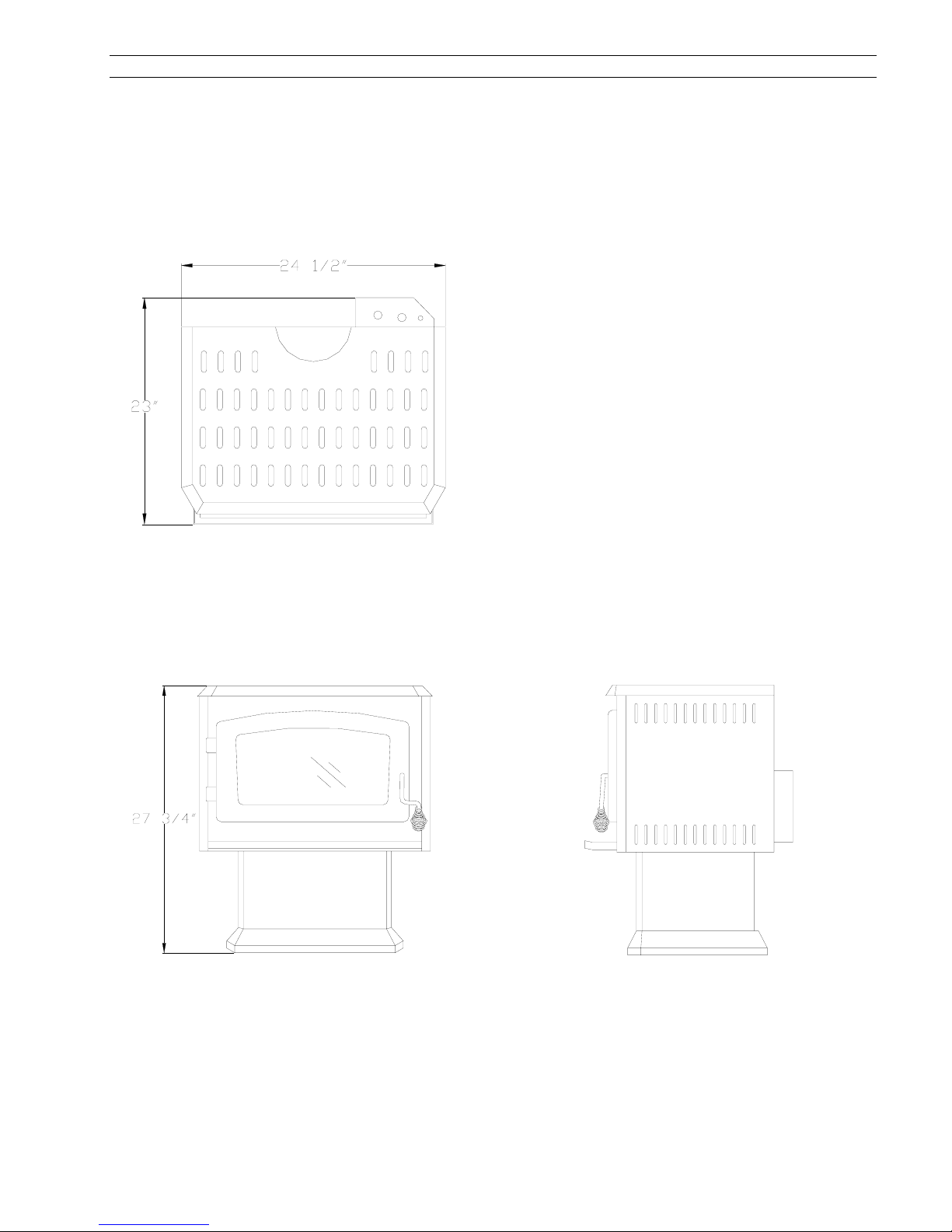
SGS Dimensions
TOP VIEW
Dimensions
Height : 27 3/4 po / 706 mm
Width : 24 1/2 po / 621 mm
Depth : 23 po / 585 mm
Ceramic Glass
8 3/4 po x 16 5/8 po
222 mm x 422 mm
Weight
115 lbs / 53 kg
Color
Metallic black
Clearances to Combustibles
• Back : 7 po 180 mm
• Side : 7 po 180 mm
• Corners : 4 po 100 mm
• Top : 36 po 915 mm
• Combustible Floor
Note 1 : Your stove has been successfully certified while installed on
a wood floor. Do not install your stove on carpeted floor. Choose a
ceramic tile or wood floor instead.
Note 1
FRONT VIEW SIDE VIEW
SGS GAS STOVES 4
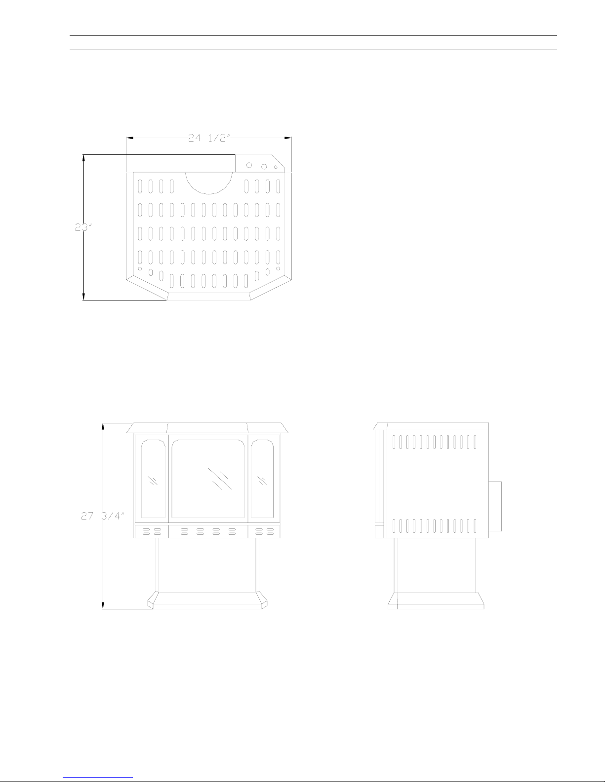
SGS II Dimensions
Dimensions
Height : 27 3/4 po / 706 mm
Width : 24 1/2 po / 621 mm
Depth : 23 po / 585 mm
Ceramic Glass
Front : 11 1/2 po x 12 1/2 po
292 mm x 318 mm
Side : 4 3/8 po x 12 1/2 po
111 mm x 318 mm
Weight
122 lbs / 56 kg
Color
Metallic black
Clearances to Combustibles
• Back : 7 po 180 mm
• Side : 7 po 180 mm
• Corners : 4 po 100 mm
• Top : 36 po 915 mm
• Combustible Floor
Note 1 : Your stove has been successfully certified while installed on
a wood floor. Do not install your stove on carpeted floor. Choose a
ceramic tile or wood floor instead.
TOP VIEW
Note 1
FRONT VIEW SIDE VIEW
SGS GAS STOVES 5
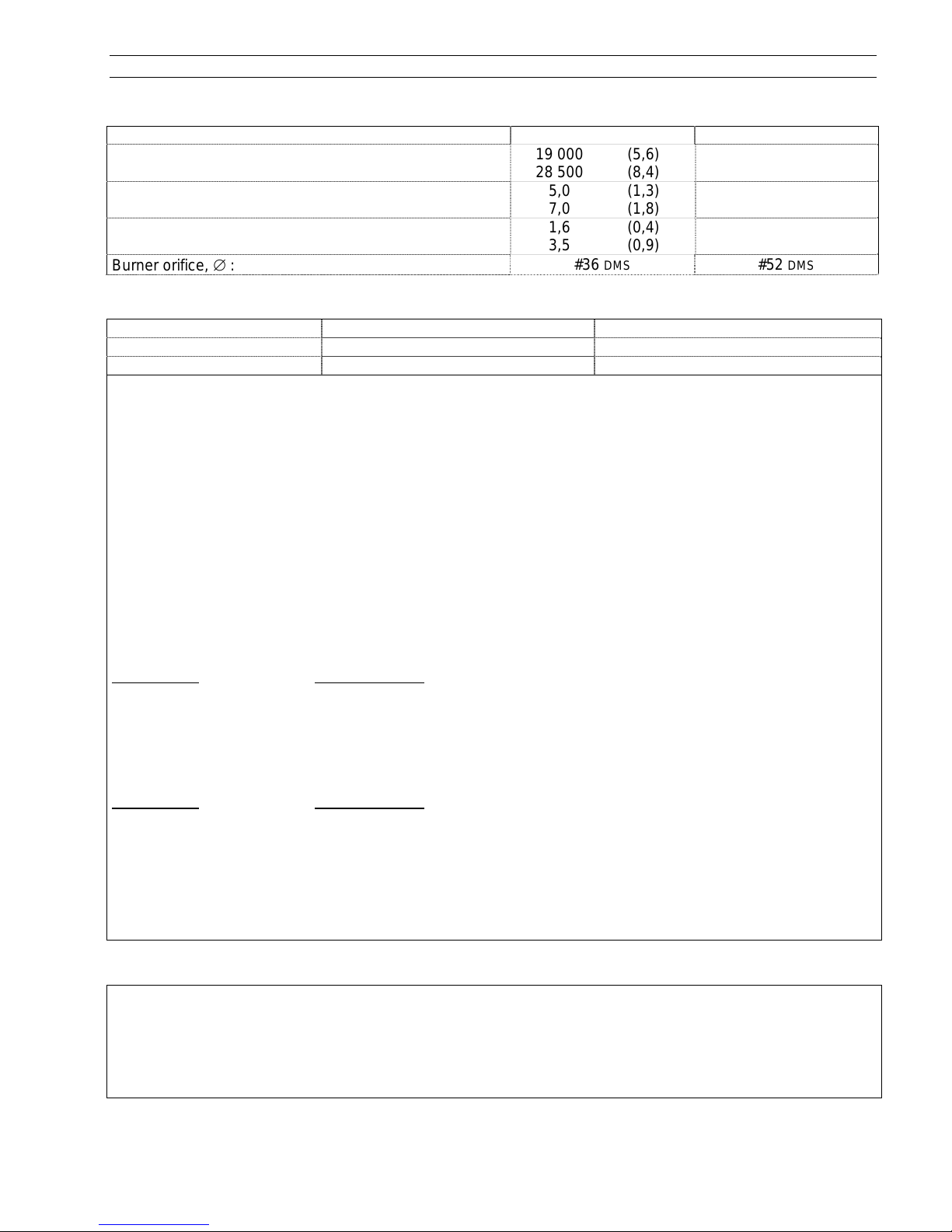
Burner
Natural Gas Propane LP
Maximum Input, BTU/h (kW) minimum :
maximum :
Inlet Pressure Inch WC (kPa) minimum :
maximum :
Manifold Pressure Inch WC (kPa) minimum :
maximum :
Burner orifice, ∅ :
19 000 (5,6)
28 500 (8,4)
5,0 (1,3)
7,0 (1,8)
1,6 (0,4)
3,5 (0,9)
DMS #52 DMS
#36
20 000 (5,9)
26 000 (7,6)
11,0 (2,8)
14,0 (3,5)
6,3 (1,7)
10,0 (2,5)
Gas Valve
Natural Gas Propane LP
S.I.T. Controls USA Model SIT 0.820.634 Nova mV Model SIT 0.820.633 Nova mV
Honeywell VS8420E8001B VS8420E8001B
YOUR STOVE IS EQUIPPED WITH A SOPHISTICATED GAS CONTROL VALVE FOR A SAFE USE. THE GAS CONTROL VALVE
OPERATES WITHOUT ELECTRICITY DUE TO THE ENERGY GIVEN BY THE PILOT FLAME AND CAPTURED BY THE THERMO
GENERATOR. (ALSO CALLED THERMOPILE). THE ADMISSION OF THE GAS FUEL TO THE BURNER IS DONE ONLY UNDER
SAFE CONDITIONS
Pressure Adjustments
For USA, above 2000 ft (610 m), see gas codes to adjust the valve operating pressure.
• Adjustments to the valve assembly must be performed by a qualified servi ce person.
• The appliance and its individual shutoff valve must be disconnected from the gas supply piping system
during any pressure testing of that system at test pressures in excess of ½ psi (3.5 kPa);
• The appliance must be isolated from the gas supply piping system by closing its individual manual shutoff
valve during any pressure testing of the gas supply piping system at test pressures equal to or less that ½
psi (3.5 kPa);
NATURAL GAS
The inlet supply or line pressure must be a minimum of 5" WC and a maximum of 7" WC. The orifice has a
#36 DMS hole.
ELEVATION INPUT RATING
0-4500 ft (0-1400m) 28 500 BTU/h (8.4 kW)
over 4500 ft (1400 m) 28 500 BTU/h (8.4 kW) less 4% per 1000 ft (300 m)
or reduce manifold pressure by 0.25 INWC per 1000 ft (300 m)
PROPANE GAS
The inlet supply or line pressure must be a minimum of 11” WC and a maximum of 14” WC. The orifice has
a #52 DMS hole.
ELEVATION INPUT RATING
0-2000 ft (0-610 m) 26 000 BTU/h (7.6 kW) Manifold pressure 10 " WC
2000-4500 ft (0-1400 m) 24 200 BTU/h (7.0 kW) Manifold pressure 8.5 " WC
over 4500 ft (1400 m) 24 200 BTU/h (7.6 kW) less 4% per 1000 ft (300 m)
or reduce manifold pressure by 1" WC per 1000 ft
NOTE : The input rating should always be checked when running this appliance for the first time. To do this,
verify inlet valve pressure and manifold pressure. Adjust manifold pressure to meet the value range as
indicated in the burner characteristics table.
.
-
Available Options
Blower Kit AC02050
• Ultra quiet tangential blower;
• Variable speed control.
Thermo Switch Kit AC05530
• Thermo switch starting the blower at 110
Thermostat Kit AC05558
O
F (43 OC) and stopping it at 90 OF (32 OC)

SGS GAS STOVES 6
INSTALLATION
Before starting any installation, make sure you know :
• Where you run your gas line ;
• What type of venting kit you need ;
• Where you run your venting pipes ;
• Where you install the terminal vent in respect with installation code ;
• Clearances to combustibles ;
• Length of horizontal and vertical runs of venting pipes.
Safety Notice
• IMPROPER INSTALLATION MAY RESULT IN A HOUSE FIRE. FOLLOW INSTALLATION DIRECTIONS. INSTALLATION MUST
BE DONE IN ACCORDANCE WITH LOCAL BUILDING CODES OR, IN THE ABSENCE OF LOCAL CODES, WITH CURRENT
CAN/CGA B 149 INSTALLATION CODES FOR GAS APPLIANCES (CANADA) AND CURRENT NATIONAL FUEL GAS
CODE ANSI Z223.1 (USA).
• A QUALIFIED INSTALLER MUST PERFORM THE INSTALLATION.
• THIS GAS STOVE MUST BE VENTED OUTSIDE.
• THIS GAS STOVE, WHEN INSTALLED WITH AN OPTIONAL BLOWER, MUST BE ELECTRICALLY GROUNDED IN
ACCORDANCE WITH LOCAL CODES OR, IN THE ABSENCE OF LOCAL CODES, WITH THE NATIONAL ELECTRICAL CODE,
ANSI/FPA 70, OR THE CANADIAN ELECTRICAL CODE, CSA C22.1.
Positioning the Stove
• Always locate the stove as near as possible to an outside wall. Keep horizontal run of vent pipe as short
as possible;
• Provide adequate clearances around air openings into the combustion chamber. Provide adequate
accessibility clearances for servicing and proper operation.
• The SGS may be installed in a bedroom provided that all required clearances are met and a wall
thermostat is installed.
• Never install the stove in a hallway or near a staircase as it may block the way in case of a fire.
• A gas appliance must not be connected to a chimney flue serving a separate solid-fuel burning
appliance other then gas.
SGS GAS STOVES 7
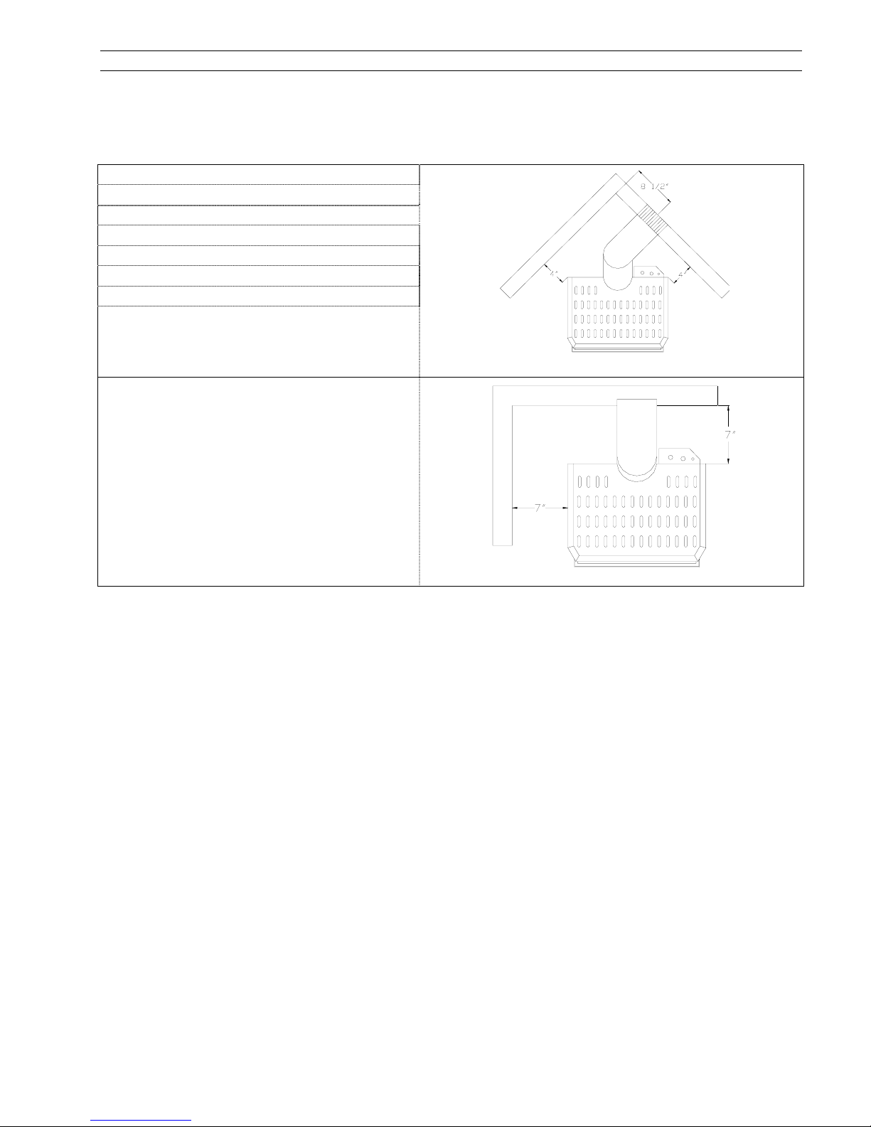
Clearances to combustibles
Clearance between the stove and any combustible material must also be maintained while installing your
appliance.
CLEARANCE
Back (in) 7
Side (in)) 7
Corners (in) 4
Top (in) 36
Front (in) 36
Pipe (in) 1 ½
Floor Combustible
Note 1
Corner Installation
Direct Installation
Note 1 : Your stove has been successfully certified while installed on a wood floor. Do not install your stove on carpeted
floor. Choose a ceramic tile or wood floor instead.
 Loading...