

Drolet SAHARA, DB03505 Owner's Manual
OWNER’S MANUAL
SAHARA WOOD STOVE
US ENVIRONMENTAL PROTECTION
AGENCY PHASE II CERTIFIED
WOOD STOVE
Verified and tested following
ULC S627 and UL 1482 Standards
by:
Manufactured by : STOVE BUILDER INTERNATIONAL INC.
250, de Copenhague, Saint-Augustin-de-Desmaures (Québec) G3A 2H3
Tel : (418 ) 878-3040 Fax : (418 ) 878-3001
www.drolet.ca
This manual is available for free download on the manufacturer’s web site. It is a copyrighted
document. Re-sale is strictly prohibited. The manufacturer may update this manual from time to time
and cannot be responsible for problems, injuries, or damages arising out of the use of information
contained in any manual obtained from unauthorized sources.
READ AND KEEP THIS MANUAL FOR REFERENCE
45138A
Printed in Canada 13-04-2012

INTRODUCTION
Stove Builder International, one of the most important wood stove and fireplace manufacturers in North
America, congratulates you on your purchase and wishes to help you get maximum satisfaction from your
wood stove. In the pages that follow, we will give you advice on wood heating and controlled combustion as
well as technical specifications regarding installation, operation and maintenance of the model you have
chosen.
The instructions pertaining to the installation of your wood stove in North America comply with ULC-S627
and UL-1482 standards.
We recommend that our wood burning hearth products be installed and serviced by professionals who are
certified in the United States by NFI (National Fireplace Institute®) or in Canada by WETT (Wood Energy
Technical Training) or in Quebec by APC (Association des Professionnels du Chauffage).
Read this entire manual before you install and use your new stove. If this stove is not properly
installed, a house fire may result. To reduce the risk of fire, follow the installation instructions. Failure
to follow instructions may result in property damage, bodily injury, or even death.
Consult your municipal building department or fire officials about restrictions and installation
requirements in your area and the need to obtain a permit.
KEEP THIS INSTRUCTIONS MANUAL FOR FUTURE REFERENCE.
CAUTIONS:
THE INFORMATION GIVEN ON THE CERTIFICATION LABEL AFFIXED TO THE APPLIANCE ALWAYS OVERRIDES
THE INFORMATION PUBLISHED, IN ANY OTHER MEDIA (OWNER’S MANUAL, CATALOGUES, FLYERS, MAGAZINES
AND/OR WEB SITES).
HOT WHILE IN OPERATION. KEEP CHILDREN, CLOTHING AND FURNITURE AWAY. CONTACT MAY CAUSE SKIN
BURNS.
DO NOT USE CHEMICALS OR FLUIDS TO IGNITE THE FIRE.
DO NOT LEAVE THE STOVE UNATTENDED WHEN THE DOOR IS SLIGHTLY OPENED DURING IGNITION.
DO NOT BURN WASTE, FLAMMABLE FLUID SUCH AS GASOLINE, NAPHTHA, OR MOTOR OIL.
DO NOT CONNECT TO ANY AIR DISTRIBUTION DUCT OR SYSTEM.
ALWAYS CLOSE THE DOOR AFTER IGNITION.
REGISTER YOU WARRANTY ONLINE
To receive full warranty coverage, you will need to show evidence of
the date you purchased your stove. Keep your sales invoice. We
also recommend that you register your warranty online at
http://www.drolet.ca/en/service-support/warranty-registration
Registering your warranty online will help us track rapidly the
information we need on your stove.
2

TABLE OF CONTENTS
TIPS ON WOOD HEATING .............................................................................................. 4
SECTION 1.0 - INSTALLATION ...................................................................................... 5
1.1 GENERAL INSTALLATION ....................................................................................................... 5
1.2 POSITIONING THE STOVE ........................................................................................................ 5
1.3 CLEARANCES TO COMBUSTIBLES AND FLOOR PROTECTOR .................................... 6
SECTION 2.0 CHIMNEY (FLUE SYSTEM) ................................................................ 13
2.1 DEFINITIONS .............................................................................................................................. 13
2.2 CHIMNEY ..................................................................................................................................... 13
2.2.1 Step by step installation of your factory-built chimney .......................................................... 15
2.2.2 Typical installation through an existing masonry chimney .................................................... 23
2.3 CHIMNEY CONNECTOR ................................................................................................................ 26
2.4 DRAFT ................................................................................................................................................. 28
2.5 OUTSIDE COMBUSTION AIR .................................................................................................. 28
2.6 THE BENEFITS OF INSTALLING A DROLET BLOWER .................................................. 29
SECTION 3.0 OPERATION .......................................................................................... 30
3.1 SAFETY INFORMATION .......................................................................................................... 30
3.2 FUEL .............................................................................................................................................. 32
3.2.1 The use of manufactured logs ................................................................................................. 33
3.2.2 Simple wood moisture test ...................................................................................................... 33
3.3 NOTES ABOUT FIRST FIRING ................................................................................................ 33
3.4 LIGHTING A FIRE ...................................................................................................................... 33
3.5 MAINTAINING THE FIRE ........................................................................................................ 34
3.6 FAN (BLOWER) OPERATION .................................................................................................. 35
SECTION 4.0 MAINTENANCE ................................................................................... 36
4.1 CLEANING AND PAINTING YOUR STOVE ......................................................................... 36
4.2 GLASS ............................................................................................................................................ 36
4.3 GASKETING ................................................................................................................................. 36
4.4 ASH REMOVAL USING THE ASH DRAWER ....................................................................... 37
4.5 CHIMNEY (FLUE) CLEANING ................................................................................................ 38
SECTION 5.0 SPECIFICATIONS ................................................................................ 39
DROLET LIMITED LIFETIME WARRANTY ............................................................ 40
3

TIPS ON WOOD HEATING
Wood is a renewable energy. It is also a very clean heat source when used with appliances that are
certified by the U.S. Environmental Protection Agency (EPA), a standard accepted in Canada as well.
EPA-certified wood stoves are different than conventional wood stoves. Burning with an EPA-certified wood
stove may therefore require that you modify some of your heating habits. To get the most satisfaction out of
your new wood-heating system, please make sure you go through the following check list.
The chimney is the engine that drives the wood-heating system. Us e a chimney that is UL-listed, with
an inner diameter to match the stove’s outlet collar (6” for all Drolet wood stoves);
Try to run the chimney inside the building for as much length as you can. A tall and warm
chimney will produce a good draft;
Try to install your chimney straight up and avoid 90 degree turns in the flue pipe and offsets in the
chimney;
Make sure that the chimney is tall enough and its top is clear of obstacles so it can produce a
stable draft;
Use a chimney thermometer installed at a distance of approximately 18 inches on the flue pipe
above the stove. Flue gases should reach at least 350oF before you close the stove’s primary air
intake completely. Operate your unit within the comfort zone indicated on the thermometer;
To reduce the risk of smoke spillage into the room upon reloading your stove, leave the primary
air intake completely open for a few minutes. This will heat up the chimney and build up draft
before you open the stove door;
Maximize hot air circulation! Our wood stoves are designed to easily receive a variable speed
blower that will improve heat distribution in front of the stove;
Remember that wood stoves produce radiant heat. Since heat rises, the use of floor traps will
greatly improve the heat transfer to rooms upstairs;
Use a mobile home approved stove if you are going to install your wood-heating system in a
mobile home. A fresh air kit must be connected to the stove. Never install your wood stove in a
bedroom;
Burn only dry cordwood;
Make sure you have a good bed of red coals before you load your stove with logs exceeding 3
inches in diameter;
Read and keep you owner’s manual. It will provide you with tips on how to run a successful
wood-heating system.
4

SECTION 1.0 - INSTALLATION
When installed and operated as described in these instructions, the Sahara wood stove is suitable for use as a
freestanding wood stove in residential installations. The Sahara wood stove is not intended for installation in
a bedroom or a mobile home.
In Canada, the CSA B365 Installation Code for Solid Fuel Burning Appliances and Equipment and the CSA
C22.1 Canadian National Electrical Code are to be followed in the absence of local code requirements. In the
USA, the ANSI NFPA 70 National Electrical Code and NFPA 211 Standard for Chimneys, Fireplaces, Vents
and Solid Fuel-Burning Appliances are to be followed in the absence of local code requirements.
In addition to the national installation and/or local building codes, fire officials (or other authorities having
jurisdiction) should be contacted to determine what restrictions and installation requirements might apply
locally.
1.1 GENERAL INSTALLATION
CAUTION:
MIXING OF APPLIANCE OR FLUE SYSTEM COMPONENTS FROM DIFFERENT SOURCES OR MODIFYING THE DIMENSIONAL
SPECIFICATION OF COMPONENTS MAY RESULT IN HAZARDOUS CONDITIONS. WHERE SUCH ACTION IS CONSIDERED,
THE MANUFACTURER SHOULD BE CONSULTED IN THE FIRST INSTANCE.
DO NOT CONNECT THIS UNIT TO ANY AIR DISTRIBUTION SYSTEM.
CRACKED AND BROKEN COMPONENTS, e.g. GLASS PANELS OR CERAMIC TILES, MAY RENDER THIS INSTALLATION
UNSAFE.
A SOURCE OF FRESH AIR INTO THE ROOM OR SPACE HEATED SHALL BE PROVIDED WHEN REQUIRED.
CONNECT THE STOVE ONLY TO A LINED MASONRY CHIMNEY CONFORMING TO NATIONAL AND LOCAL BUILDING
CODES FOR USE WITH SOLID FUEL, OR TO A LISTED FACTORY BUILT CHIMNEY SUITABLE FOR USE WITH SOLID FUEL.
1.2 POSITIONING THE STOVE
It is very important to position the wood stove in an area that will favour the most efficient heat distribution
throughout the house. The stove should therefore be installed in the room where the most time is spent, and
in the most spacious room possible. Recall that wood stoves produce radiating heat, the heat we feel when we
are close to a wood stove. A wood stove also functions by convection, that is through the displacement of hot
air accelerated upwards and its replacement with cooler air at the floor level. The stove’s convection effect is
facilitated by the installation of a blower.
5
1.3 CLEARANCES TO COMBUSTIBLES AND FLOOR PROTECTOR
To install your appliance correctly, it is extremely important to respect all clearances to any combustibles as
indicated on your stove’s certification label.
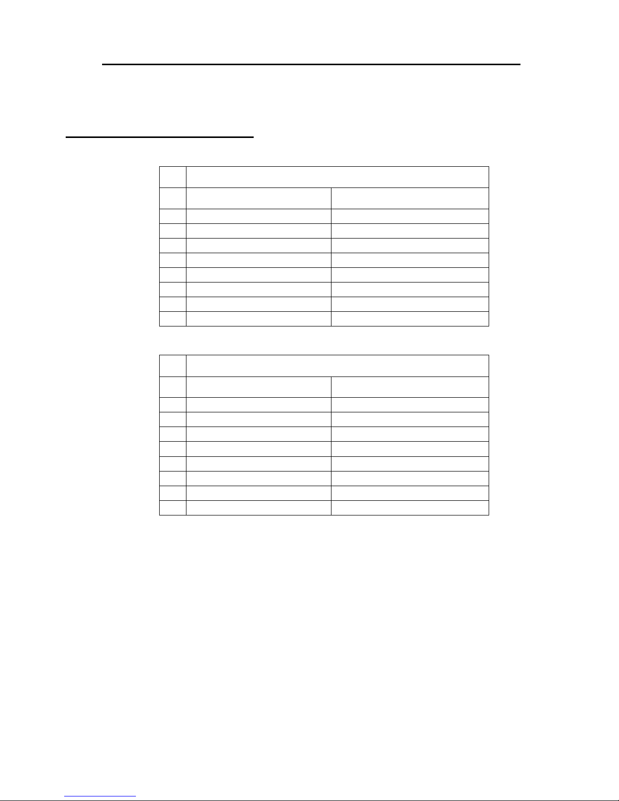
Clearances to combustible materials
(see figure 1.3 to match each letter to a clearance)
CLEARANCES (SINGLE WALL PIPE)
A
B
C
D
E
F
K
L
CANADA USA
16" (410 mm) 16" (410 mm)
15" (385 mm) 15" (385 mm)
9" (230 mm) 9" (230 mm)
19" (485 mm) 19" (485 mm)
26" (665 mm) 26" (665 mm)
20" (510 mm) 20" (510 mm)
48" (1220 mm) 48" (1220 mm)
84" (213 cm) 84" (213 cm)
A
B
C
D
E
F
K
L
CLEARANCES (DOUBLE WALL PIPE)
CANADA USA
10" (255 mm) 10" (255 mm)
15" (385 mm) 15" (385 mm)
9" (230 mm) 9" (230 mm)
13" (335 mm) 13" (335 mm)
26" (665 mm) 26" (665 mm)
20" (510 mm) 20" (510 mm)
48" (1220 mm) 48" (1220 mm)
84" (213 cm) 84" (213 cm)
6
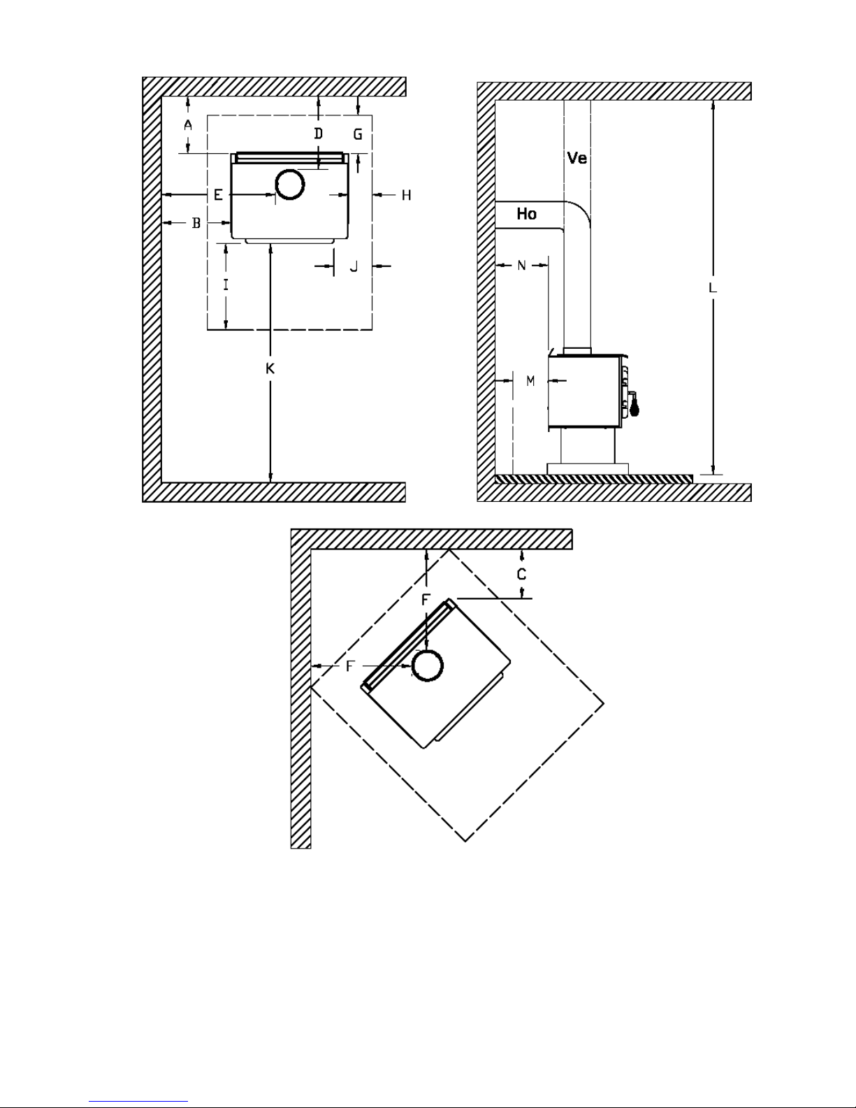
FIGURE 1.3 Clearances to combustible materials and floor protection
7
Floor protector
If the stove is to be installed on top of a combustible floor, it must be guarded by a non combustible material
as shown on figure 1.3 (see the dotted line area).
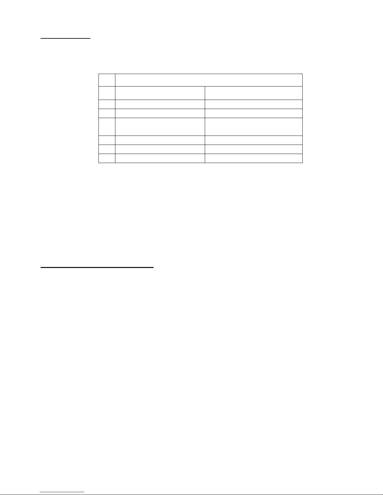
FLOOR PROTECTOR*
G
H
I
J
M
N
CANADA USA
8’’ (205 mm) – Note 1 N/A (Canada only)
8’’ (205 mm) N/A (Canada only)
18’’ (460 mm)
From door opening
16’’ (410 mm)
From door opening
N/A (USA only) 8’’ (205 mm)
8’’ (205 mm) N/A (Canada only)
N/A (USA only) Note 2
*Steel with a minimum thickness of 0.015’’ (0.38 mm) or ceramic tiles sealed together with grout. No
protection is required if the unit is installed on a non-combustible floor (ex: concrete).
Note 1 : The floor protection at the back of the stove is limited to the stove’s required clearance if such
clearance is smaller than 8 inches (205 mm).
Note 2 : Only required under the horizontal section of the connector. Must exceed each side of the
connector by at least 2 inches (51 mm).
Reduced clearances using shielding
You may decrease the clearances by installing heat radiation shields between the walls or the ceiling and the
stove. These heat radiation shields must be installed permanently, and can include sheet metal, a rigid noncombustible sheet or a masonry wall.
Clearances of not less than 1" (25 mm) and not more than 3" (76 mm) between the bottom of the shield and
the floor and not less than 3" (76 mm) between the top of the shield and the ceiling must be respected to allow
vertical air circulation behind the shield. The shield must extend 20" (500 mm) above the stove top and 18"
(450mm) to each side of the stove (see graphic 1).
Following the installation of such a heat radiation shield, the clearances mentioned on the stove certification
plate may be reduced as stated in the following table.
8
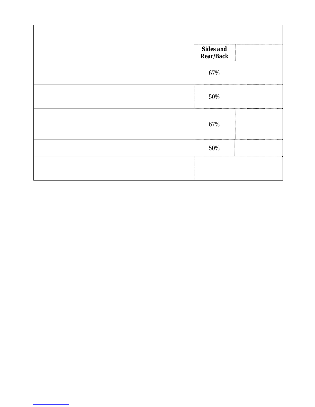
TYPE OF PROTECTION
Sheet metal, a minimum of 0,024" (0,61mm) spaced out at
least 1" (25mm) by non-combustible spacers (see
graphic 2).
Ceramic tiles, or an equivalent non-combustible material on
fire-proof supports spaced out at least 1" (25 mm) by noncombustible spacers (see graphic 3).
Ceramic tiles, or an equivalent non-combustible material on
fire-proof supports with a minimum of 0,024" (0,61 mm) sheet
metal backing spaced out at least 1" (25 mm) by noncombustible spacers (see graphic 4)
Reducing Clearances With
Shielding
Sides and
Rear/Back
67% 50%
50% 33%
67% 50%
Top
Brick spaced out at least 1" (25 mm) by non-combustible
spacers (see graphic 5)
Brick with a minimum of 0,024" (0,61 mm) sheet metal
backing spaced out at least 1" (25 mm) by non-combustible
spacers (see graphic 6).
50% N/A
67% N/A
9
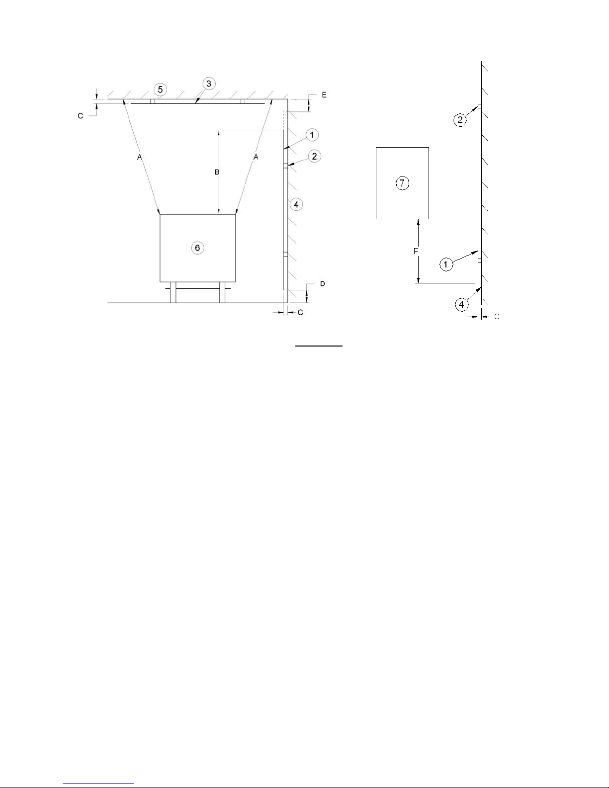
Graphic 1
A- Minimum clearance required between the appliance and an unshielded combustible ceiling.
B- 20 in. (500 mm) minimum;
C- 1 in. (25 mm) minimum;
D- Between 1 in. and 3 in. (25 mm and 75 mm);
E- 3 in.(75 mm) minimum;
F- 18 in. (457 mm) minimum.
1- Shielding;
2- Non-combustible spacers;
3- Ceiling protector;
4- Combustible wall;
5- Ceiling;
6- Appliance (side view);
7- Appliance (top view).
10
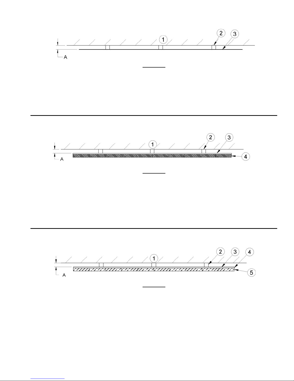
A- 1 in.(25 mm) minimum;
1- Combustible wall;
2- Non-combustible spacers;
3- 0.024’’ (0.61mm) sheet metal.
A- 1 in. (25 mm) minimum;
1- Combustible wall;
2- Non-combustible spacers;
3- Non-combustible support;
4- Ceramic tile or non-combustible material.
Graphic 2
Graphic 3
A- 1 in. (25 mm) minimum;
1- Combustible wall;
2- Non-combustible spacer;
3- 0.024’’ (0.61 mm) thick sheet metal;
4- Non-combustible support;
5- Ceramic tile or non-combustible material.
Graphic 4
11
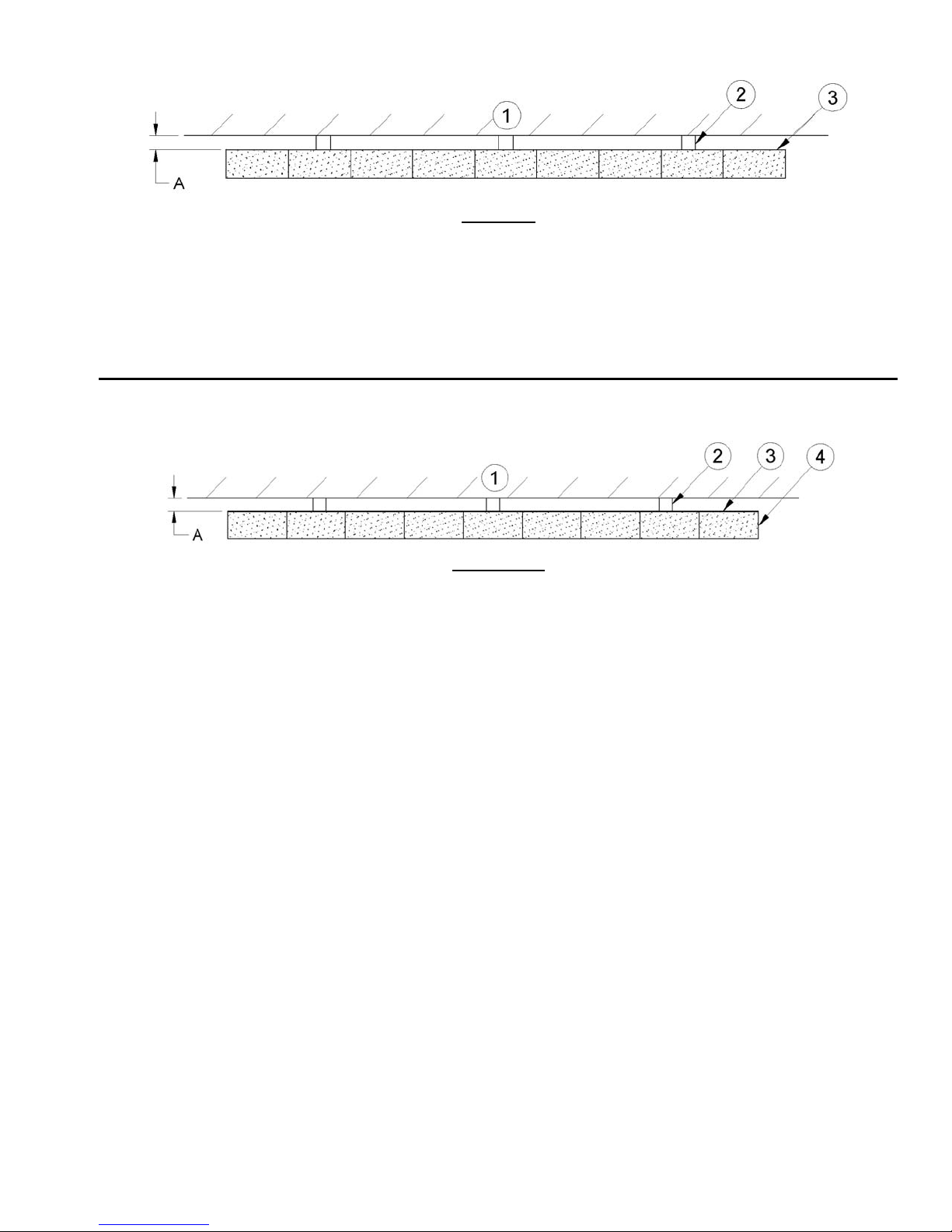
A- 1 in. (25 mm) minimum;
1- Combustible wall;
2- Non-combustible spacers;
3- Brick.
A- 1 in. (25 mm) minimum;
1- Combustible wall;
2- Non-combustible spacers;
3- 0.024’’ (0.61 mm) thick sheet metal;
4- Brick.
Graphic 5
Graphique 6
12
 Loading...