

Page 1

Sunfire Gladiator
SG-3CRD-853
Drive Medical Design & Manufacturing
99 Seaview Boulevard
Port Washington, NY 1105
Phone: 877-224-0946 Fax: 516-9984601
www.drivemedical.com
Page 2
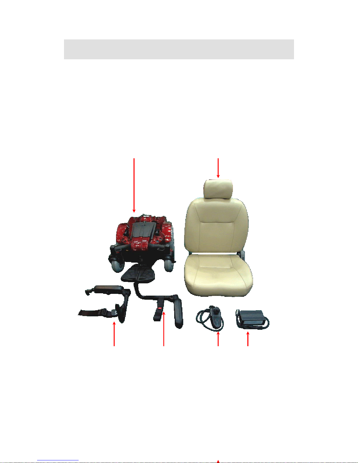
COMPONENTS
Your power wheelchair is shipped partially disassembled for protection
during shipping. After unpacking, please check whether you have r
the following main components as our standard specification (See Fig.1
eceived
).
Mainframe with motor 4. Armrest (right)
1 2
1.
2. Seat 5. Armrest (left)
3. Controller 6. Charger
4 5 3 6
(Fig 1)
Page 3

SAFETY INSTRUCTION
Operation of Chair
1. Always ensure that the power is switched off when getting in or out of the power
wheelchair. This will eliminate the possibility of accidentally activating the
joystick and causing injury to yourself or others.
2.Always check that the drive wheels are engaged (drive mode) before driving.
3.Set the speed control knob according to your driving ability and the environment in
which you are going to operate. We recommend that you keep your speed at the
slowest position (fully press the deceleration button) until you are familiar with the
driving characteristics of the vehicle. We also recommend that you use the slowest
speed when using your power wheelchair indoors.
4.Always reduce your speed when making sharp turns.
5.Do not switch off the power when the wheelchair is still moving forward. This will
bring the chair to an extremely abrupt stop.
6.Avoid jerky stop/start motions as it will result in excessive current draw from the
batteries, increased tire wear and the rapid wearing of the gearboxes and motors.
7.To brake in an emergency, simply release the joystick.
Ramps and Curbs
8. When driving up or down ramps, be sure to check that the angle of the slope is l
than 10 degrees (slopes about 1/6). Also check that ramp surface is roughened to
prevent slipping. Never drive across a slope or turn sharply on a slope.
ess
9. When driving up curbs, always check the height of the curb to ensure that it does
not exceed 1-1/2”(40mm) height.
Transfers, Reaching and Bending
10. Transferring on and off the unit requires a good sense of balance. To eliminate the
possibility of injury, we recommend performing the following tasks before
attempting a transfer:
→ Position chair so that the distance between your power chair and the object to
which you are transferring is close enough for a safe transfer.
→ Turn the power off
→ Ensure that your power chair not in freewheel mode.
→ Flip up or remove armrests
Page 4

→ Flip up footplate or remove footrests
→ Turn both caster wheels towards the transfer direction to improve power chair
stability during transfer.
11. When reaching, bending or leaning while seated on your power chair, make sure
that you maintain a stable center of gravity to keep the power chair from tipping.
General
12. Always use a seat belt, and keep feet on the footplate at all times.
13. For safety reason, make sure that your weight does not exceed the recommended
weight limit of the wheelchair. Consult your dealer for the specified weight limits
for your particular model.
14. Do not attempt to lift or move a power chair by any of its rem ovable parts. Pe
injury and damage to the power chair may result.
rsonal
anual.
17. erate your vehicle if it is not functioning properly.
icle. Failure to obey
19. es, portable
se While Under The Influence Of Medication Or Alcohol
15. Do not stand on the footplate directly.
16. Never try to use your wheelchair beyond its limitations as described in this m
Do not op
18. Do not connect any electrical or mechanical device to the veh
this instruction may result in injury and will void the warranty.
Never use electronic radio transmitters such as CB, walkie-talki
computers or cellular phones while using the vehicle without first turning the
vehicle off.
U
affect your
21. the influence of alcohol, as this
lectromagnetic interference (EMI) from Radio Wave Sources
ns, has
oot-
20. Check with your physician if you are taking any medication that may
ability to operate your power wheelchair safely.
Do not operate your vehicle while you are under
may impair your ability to operate your power chair in a safe manner.
E
The rapid development of electronics, especially in the area of communicatio
saturated our environment with electromagnetic(EM) radio waves that are emitted by
television, radio and communication signals. These EM wave are invisible and their
strength increases as one approaches the source. All electrical conductors act as
antennas to the EM signals and, to varying degrees, all power wheelchairs and sc
ers are susceptible to electromagnetic interference(EMI). The interference could result
in abnormal, unintentional movement and/or erratic control of the vehicle. The United
Page 5

States Food and drug Administration (FDA) suggests that the following statement be
incorporated to the user’s manual for all power wheelchairs. Power wheelchairs and
motorized scooters (in this section, both will be referred to as powered wheelchairs)
may as susceptible to electromagnetic interference (EMI), which is interfering
electromagnetic energy emitted from sources such as radio stations, TV stations
amateur radio (HAN) transmitter, two-way ra dios and cellular phones. The interfer
(from radio wave sources) can cause the powered wheelchair to release its b
move by itself or move in unintended directions. It can also permanently damage the
powered wheelchair’s control system. The intensity of the EM energy can be measure
in volts per meter (V/m) each powered wheelchair can resist EMI up to a certain
intensity. This is called “immunity level”. The higher the immunity level, the greater
the protection. At this time, current technology is capable of providing at least 20 V/m
of immunity level, which would provide useful
protection against common sources of radiated EMI.
,
ence
rakes,
d
e chance of unintended brake
and(CB)
2. ng
3. t or brake release occurs, turn the powered wheelchair off as
4. accessories or components, or modifying the powered wheel-
red
5
. Report all incidents of unintended movement or brake release to the powered
y.
URN OFF YOUR POWERED WHEELCHAIR AS SOON AS POSSIBLE WHEN
llable direction.
The FD ers of power wheelchairs asking them to test
0
Following the warnings listed below should reduce th
release or powered wheelchair movement that could result in serious injury:
1. Do not turn on hand-held personal communication devices such as citizens b
radios and cellular phones while the powered wheelchair is turned on.
Be aware of nearby transmitters such as radio or TV stations and try to a void comi
close to them.
If unintended movemen
soon as it is safe.
Be aware that adding
chair, may make it more susceptible to interference from radio wave sources
(Note: It is difficult to evaluate the effect on the overall immunity of the powe
wheelchair).
wheelchair manufacturer, and note whether there is a radio wave source nearb
T
EXPERIENCING THE FOLLOWING:
‧ Unintentional motions
‧ Unintended or uncontro
‧ Unexpected brake release
A has written to the manufactur
new products to be sure they provide a reasonable degree of immunity against EMI.
The FDA requires that a powered wheelchair sho uld have an immunity level at least 2
V/m, which provides a reasonable degree of protection against more common sources
Page 6

of EMI. The higher the immunity level, the greater the protection. Your powered
wheelchair has an immunity level of 20 V/m which should protect against comm
sources of EMI.
on
ENVIRONMENTAL CONDITIONS
En rmance of your power
wer wheelchair is susceptible to damage to electronic or
B)
s of the power wheelchair are susceptible to change in tempera-
)
and 122℉(50℃).
At extrem e batteries may freeze, and your power wheelchair may
s
r
vironmental conditions may affect the safety and perfo
wheelchair. Water and extreme temperatures are the main elements that can cause
damage and effect performance.
A) Rain, Sleet and Snow
If exposed to water, your po
mechanical components. Water can cause electronic malfunction or promote
premature corrosion of electrical components and frame.
Temperature
Some of the part
ture. The controller can only operate in temperature that ranges between 18℉(-8℃
e low temperatures, th
not be able to operate. In extreme high temperatures, it may operate at slower speed
due to a safety feature of the controller that prevents damage to the motors and othe
electrical components.
Page 7
ASSEMBLY INSTRUCTION
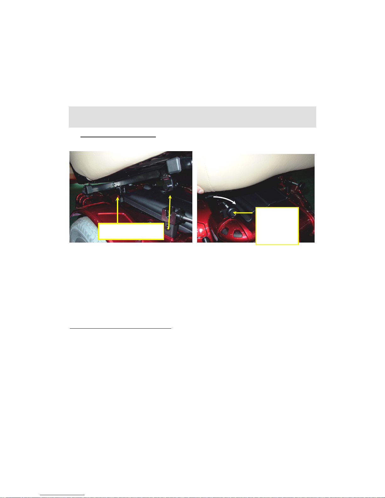
1. Installing the Seat (#2)
Connection point
(Fig 2) (Fig 3)
Slide the seat (#2) i ame (#1)(See
ig2), put down the seat and connect the front connection point and make sure that
.Installing the Armrest Frame
Front
Connection
Point
nto the Connection points (both sides) in the Main fr
F
tighten the tension knob in the front connection point. (See Fig3).
2
rest frame (with left-#5 and Right-#4 each) into the seat frame (See Fig 4),
armrest. (See Fig 5)
I
nsert the arm
then use the tension knob to lock the
Page 8
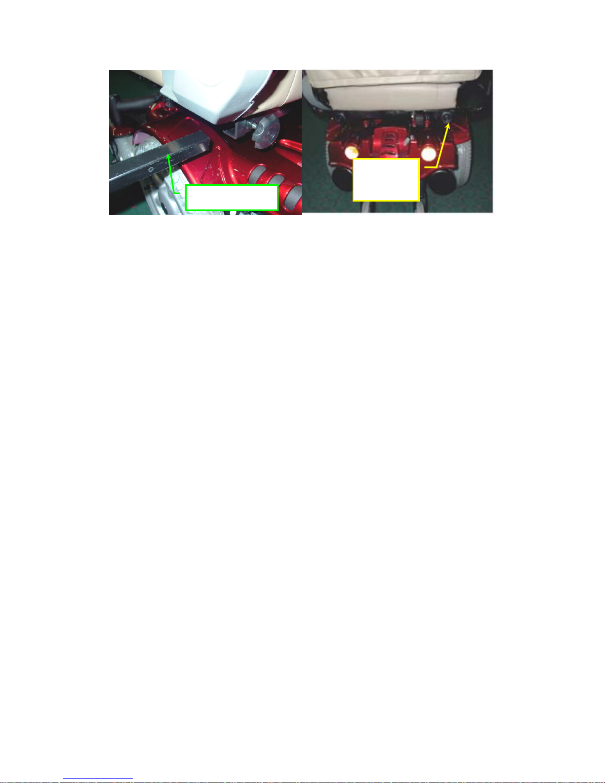
Tension
knob
Armrest Frame
(Fig 4) (Fig 5)
Page 9
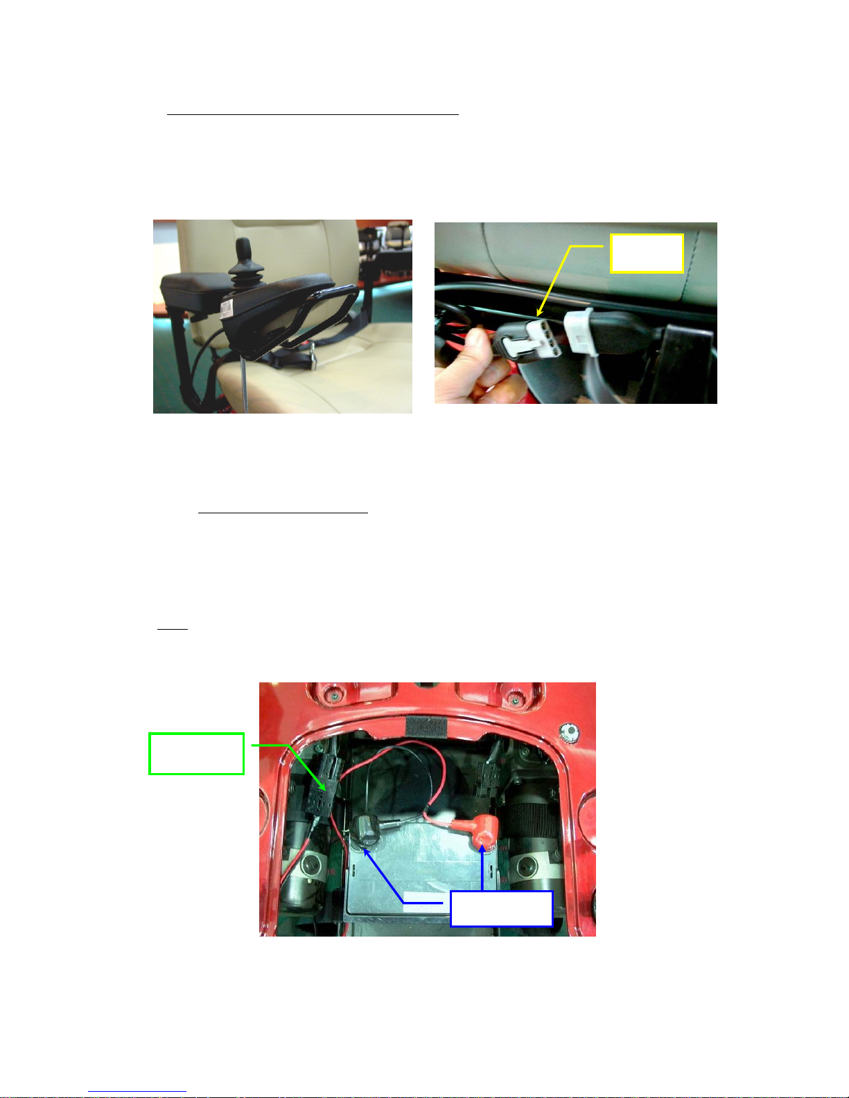
3. Installing controller and connect cables
Assemble the controller (#3) on right armrest (#6) bracket with 2 screws.(See Fig
6)There is one plug (4 pins) in the other end on the controller . Please connect the 4 p
plug with mainframe (#1) and make sure they are tightly connected.(See Fig 7)
ins
4 pins
(Fig 6) (Fig 7)
Note: Installing the Batteries (y
ou can omit this step if your scooter already
assembled the batteries)
Take out the cover from the base frame slightly. Put the batteries to the battery loops
and connect the cable (2 ends) with the battery positive and negative poles in batteries.
(See Fig 8)
Note: There is a battery circuit diagram labeled on the backside of the shroud. Please
refer this diagram before you assemble the battery.
Connected
(Fig 8)
Page 10
ADJUSTMENTS FOR SEATING CONFORT
To maximize seating comfort, your power wheelchair lets you adjust:
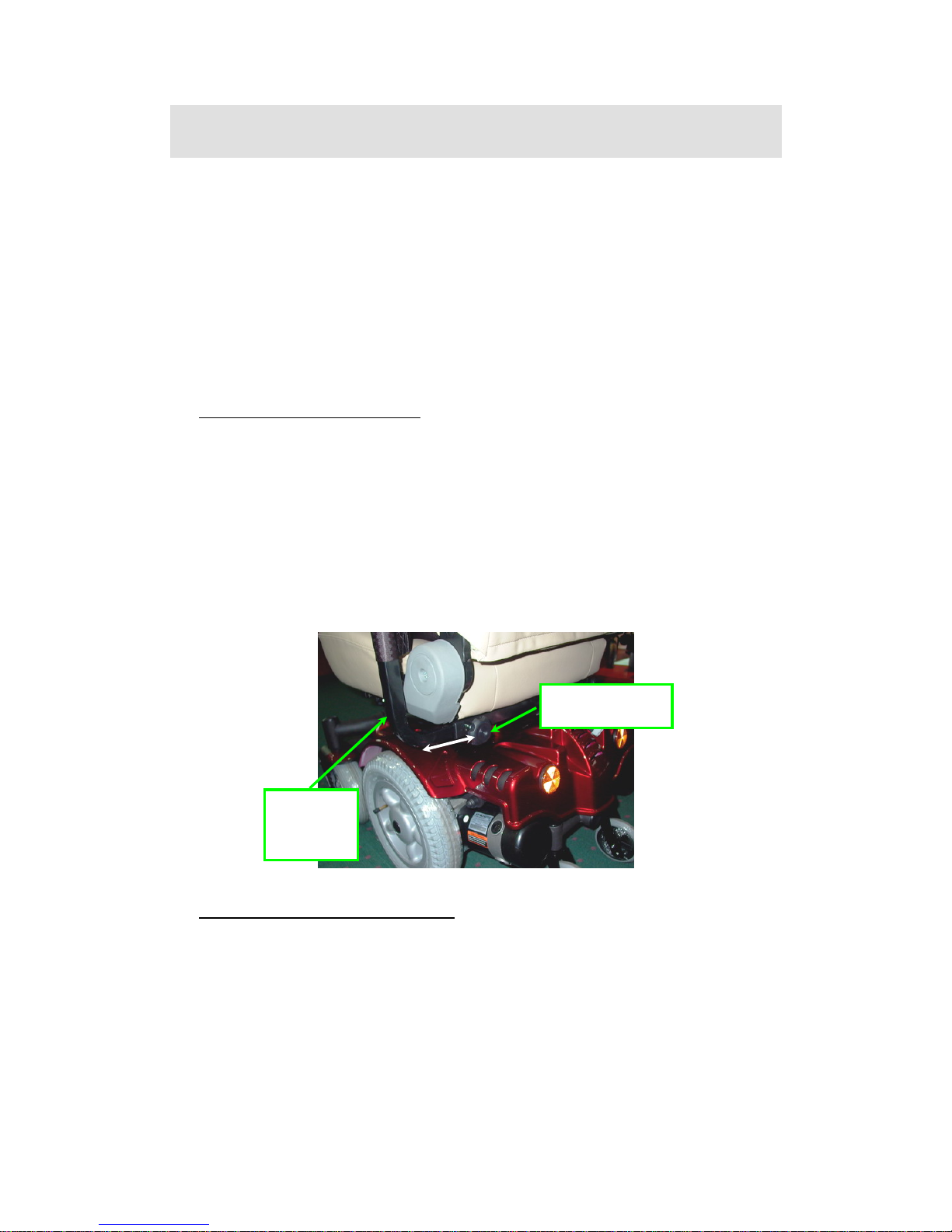
→Armrest width
→Controller position
→Backrest angle
→Headrest height
A. Armrest Width Adj ustment
→ Loosen the tension knob
→ slide the armrest frame to your desired width
→ tighten the tension knob.(See Fig 9)
Note: The armrests on the unit are total folding by manual operation.
Tension Knob
Armrest
Frame
(Fig 9)
B. Controller Position Adjustment
→ Loosen the T- knob
→ slide the armrest frame to your desired length
→ tighten the T-knob.(See Fig 10)
Page 11
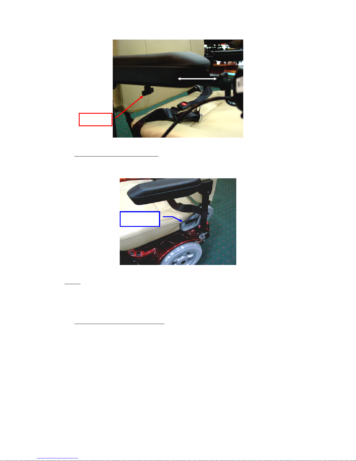
T-Knob
(Fig 10)
C. Backrest Angle Adjustment
Lift up the lever located the left side of the seat and adjust the backrest position to y
desired angle.(See Fig 11)
our
Seat Lever
(Fig 11)
Note: There are 5 different angles range when you slightly adjust the backrest to fit
yours comfortable seating from the 105° to 135°.
D. Headrest Height Adjustment
→ press the button and lift up or down the headrest to your desired position
→ let the button lock into the corresponding notch. (See Fig 12)
Note: There are 4 different positions to adjust your headrest height.
Page 12
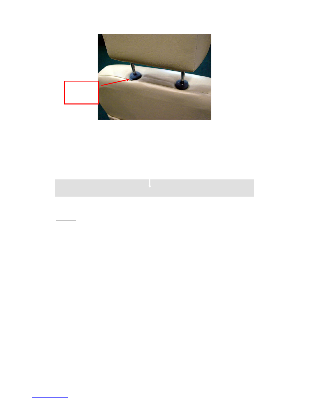
Press this
Button
(Fig 12)
OPERATION
The power wheelchair is simple to operate. However, we recommend that you read
carefully the following instructions to become familiarized with your new vehicle.
Caution:
Before you turn the power on, always be aware of the environment that surrounds you
to select your desired speed. For indoor environments we recommend that you select
the slowest speed setting. For outdoor operation of this vehicle we recommend that y
select a speed that is comfortable for you to control it safely.
ou
See
The following steps are required to operate your vehicle safely with the controller (
Fig 13)
Page 13
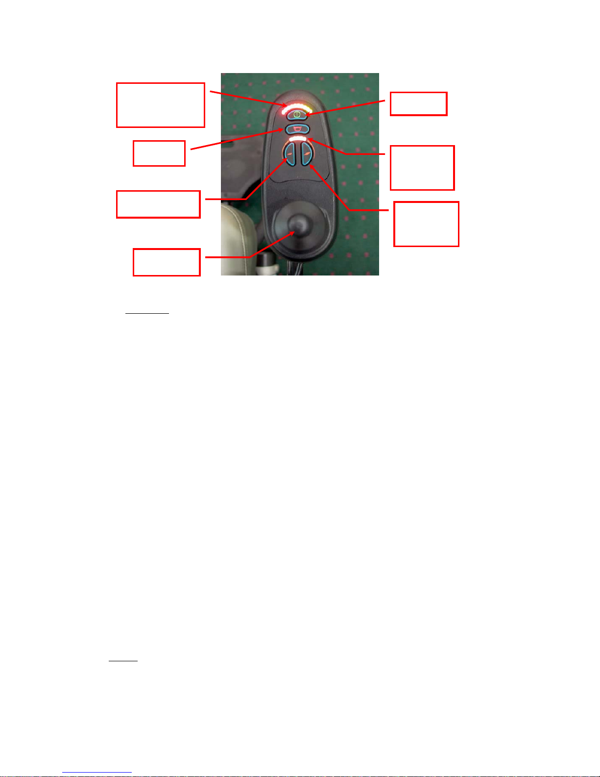
(Fig 13)
A.
Driving:
1. Controller ON/OFF Switch
Press the ON/OFF button (I/O) switch located in front of the joystick to activate
your power wheelchair. The battery condition meter will light up to indicate the
current charge of your battery. Pressing the ON/OFF button again will deactivate
the controller.
2. Speed Control
The speed control buttons allow you to set the forward speed to your desired se
Pressing the speed-increasing button will set the speed at the faster settings while
the speed will slow down if you press the speed-decreasing button. The controller
sets the reverse speed, acceleration and deceleration proportion-
tting.
ystick
ally and automatically for your safety.
3. Joystick
The joystick controls the direction and speed of your vehicle, pointing the jo
away from the neutral position (center) will move the vehicle in the direction
where the joystick is pointing. The farther away (forward/backward) the jo ystick is
from the neutral position, the faster the vehicle will go. The farther away to the
right/ left the joystick is pointing, the sharper the turn of the vehicle will be. To
operate the vehicle by gently pushing the joystick in the direction you want to go.
Returning the joystick to its neutral position (center) will reduce the speed and stop
the vehicle by automatically applying the electromagnetic brakes.
Notes:
→After pressing the controller ON/OFF switch, allows two seconds to elapse before
Joystick
Speed
indication
Speed
control
Battery
Condition LED
ON/OFF
HORN
Speed control
Page 14

engaging the joystick. This is a safety feature to prevent sudden start.
→Gentle operation of the joystick will result in smoother transitions in speed a
direction, while sharp operation of the joystick will result in drastic trans
in direction and velocity.
nd
itions
→When the wheelchair is in operation, the surface of the charger will become
slightly hot.
→In case of emergency, let go of the joystick and the chair will come to a stop.
B. Controller Display
The controller display is a multifunction visual display. It can provide four types o
information: 1)ON/OFF status , 2)battery condition meter, 3) Horn , 4)
acceleration , 5) deceleration buttons and 6)speed indication.
f
t,
1. ON/OFF Status
When the power is on, the controller’s LED will be lit up. If the LED is not li
the controller is OFF.
2. Battery Condition Meter
The battery condition meter is composed of 10 segments (three of red, four of
yellow, and three of green). It enables you to monitor battery charge. The
battery condition meter indicates the approximate amount of battery charge
left.
→Red, yellow and green LEDs indicate that the batteries are fully charged
→Red and yellow LEDs indicate that you should charge the batteries if
possible.
→Red LEDs indicate that you should charge the batteries as soon
as
possible,
because low battery voltage may cause your power wheelchair to become
inoperative.
Note:
When the batteries begin to approach a discharged state, the first red LED
will begin to flash slowly, reminding you that the batteries need
to be
charged immediately.
C. Free-Wheeling:
Because the motors are designed to engage the electromagnetic brakes when the
Page 15
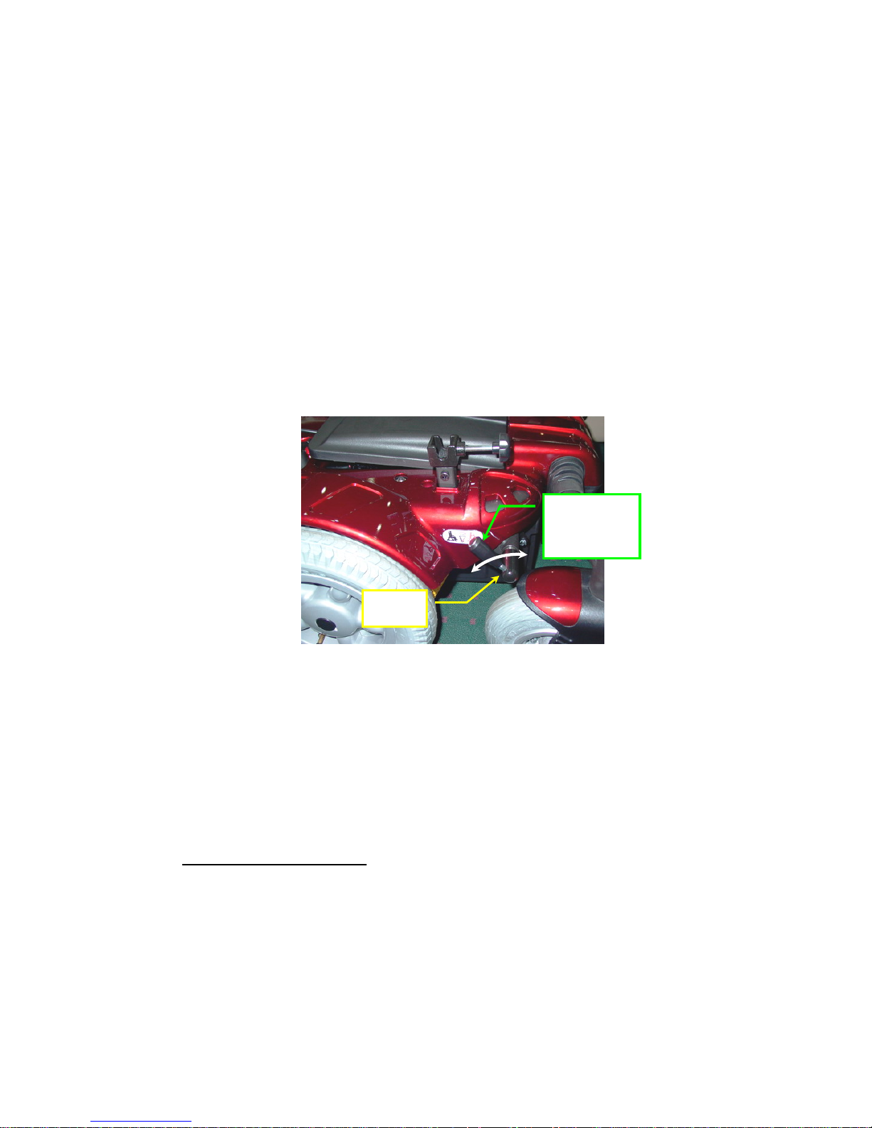
vehicle is not in use or when the power is OFF, they also have a manual feature th
allows them to “free-wheel”. Free-wheeling is accomplished by turning the
free-wheeling levers to the freewheeling position.(See Fig 14)
at
Warning !
→Never free-wheel your power wheelchair on a slope.
→Never free-wheel the motors while operating your vehicle.
→Always remember to engage the motors before turning the power back ON.
Note: The free-wheeling lever is designed by special construction to operate
when you want to disengage the electromagnetic brakes. Please press the end
cap and rotate the lever when disengage. (See Fig 14)
(Fig 14)
Warning !
→Never free-wheel your power wheelchair on a slope.
→Never free-wheel the motors while operating your vehicle.
→Always remember to engage the motors before turning the power back ON.
Free-wheel
Lever
Press
D. Electromagnetic Brakes:
Your power wheelchair comes with an Electromagnetic Brakes, i.e. an automatic
magnetic disc safety brake which is also known as Fail-Safe brake. The Electromagnetic Brakes are automatic and work when the power wheelchairs is ON but in a
steady state (i.e. Joystick is released to the neutral position), even when the chair is
on a slope. The Electromagnetic Brakes will also be set when-
ever the power wheelchair is OFF, but the motor levers are in the engaged (vertical)
Page 16
position.
Note: Please refer to the section titled to check brakes in the Maintenance & Repair
section to make sure brakes are in good condition.
E. Thermal Protection:
Your power wheelchair controller is equipped with a safety system called thermal
rollback. A built-in circ uit monitors the temperature of the controller and motors,
the controller reduces the motor voltage and speed of the power wheelchair. The
reduction of the speed allows the electrical components to cool down. Although
your power wheelchair will resume its normal speed when the temperature returns
to a safe level, we recommend that you turn the power off and wait for 5 minutes
before restarting to allow the components to cool down if you find that you have
lost speed suddenly.
F.
Main Circuit Breaker:
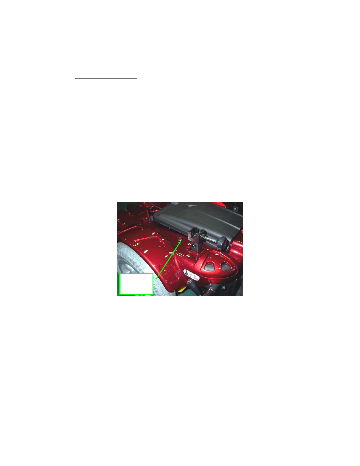
Please see Fig 15 to check the circuit breaker location in P16.
Breaker
(Fig 15)
The main circuit breaker monitors the electric current drawn from the battery. It is a
safety feature built in your power wheelchair for your extra safety. When the
batteries and motors are heavily strained (e.g., from excessive loads),the main
circuit breaker will trip to prevent damage to the motors and the electronics. If the
circuit breaker trips, wait for approximately one minute and then depress the b
to reset it. Then turn on the controller power, and continue normal opera-
utton
tion. If the main circuit breaker continues to trip repeatedly, contact your
authorized dealer.
Page 17

BATTERIES & CHARGER
BATTERY
We recommend that you use deep-cycle batteries that are sealed and maintenance
free for your power wheelchair. Both sealed lead-acid (SLA) and gel cell are
deep-cycle batteries and are similar in performance. Deep-cycle batteries are
specifically designed to provide power, drain down, and then accept a relatively
quick recharge. Lead-acid batteries should be charged as often as possible.
Specification of the battery that we recommend:
Type:
Size:
Voltage:
Amp Hours:
Deep –cycle sealed lead-acid or gel cell
50AH, or 62 AH
12V each
50 or 62 amp hours
Depending on the use, terrain and driving conditions, the batteries will provide a
range of 22.4 miles of travel. However, even if the power chair is not in use, we
recommend that the batteries are charged periodically.
Note:
→Do not use any automotive batteries. They are not designed to handle a long,
deep discharge and also are unsafe for use in power chairs.
→The useful life of a battery is quite often a reflection of the care it receives.
CHARGER
The battery charger takes the standard wall outlet voltage (alternating current )and
converts it into DC (direct current).The batteries use direct current to run your
power chair. When the batteries are fu lly char ged, the am perage from the char ger is
almost zero. This is how the charger maintains a charge but does not overcharge the battery.
Note: The batteries can not be charged after they are discharged to nearly zero
voltage.
CHARGING INSTRUCTIONS
To recharge the batteries, follow the steps below:
→Place your power wheelchair close to a standard electrical wall outlet.
→Turn the controller power OFF
Page 18
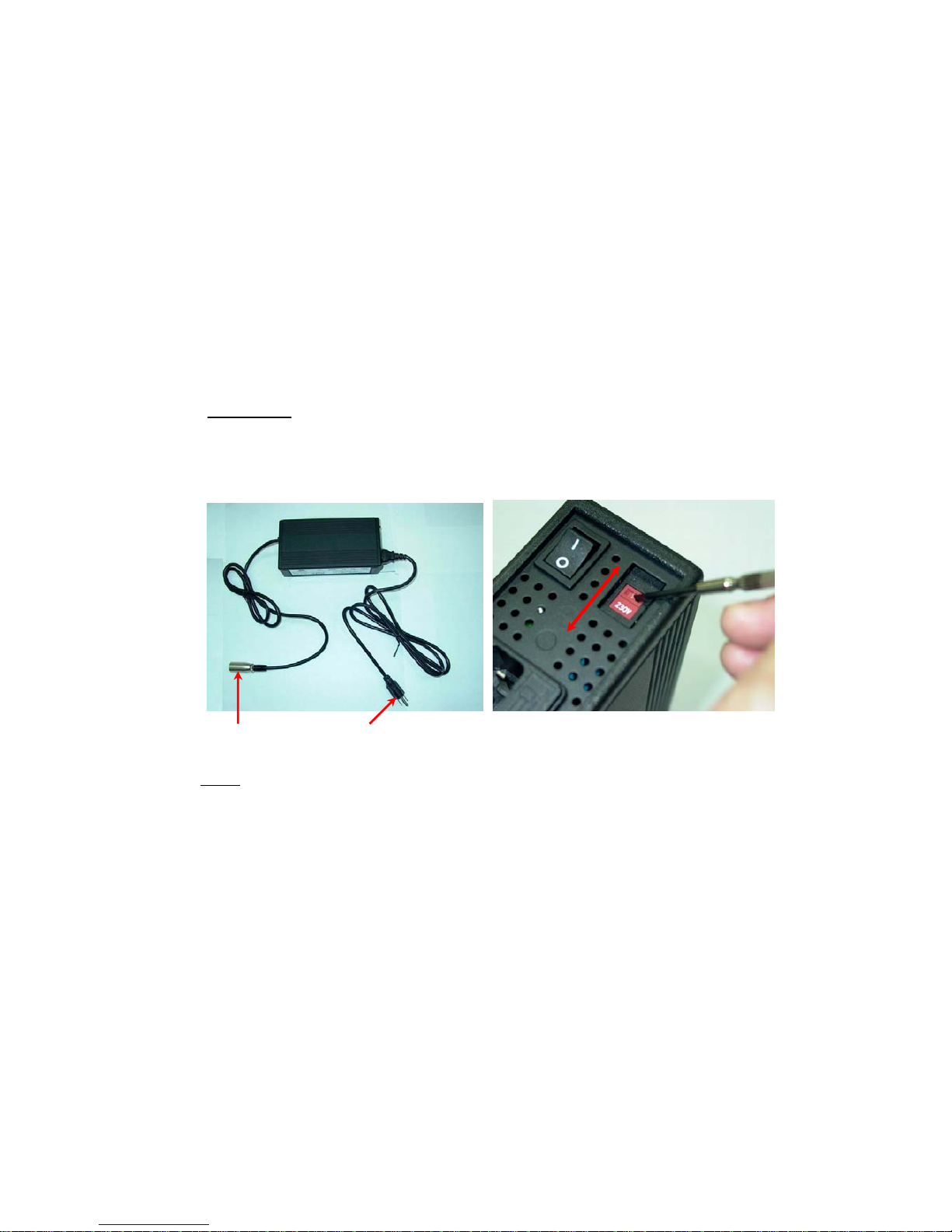
→Plug the charger power cord (Round head) into the controller
→Plug the charger power cord into a standard wall outlet. A red and a yellow (if
battery charge is low) LEDs will illuminate.
→When charging is completed, the yellow LED will turn green.
→Disconnect the charger power cord from the wall outlet when the batteries are
fully charged. (See Fig 16)
Important!
Do not use for voltage input unless specified. Make sure your present voltage
input (110V or 220V) and adjust manually. (See Fig 17)
plug-in controller plug-in wall outlet (Fig 17)
(Fig 16)
Note:
→Always charge your batteries in well ventilated areas.
→The charger is intended for indoor use only. Protect from moisture.
→For maximum performance , it is recommended that you replace both batteries
at the same time if the batteries are weak.
→If the chair will not be used for a long period of time, arrange to have the
batteries fully charged for at least once every month.
According to the battery type and condition of the batteries, they usually can be
Page 19

fully charged in 4-10 hours. This will be indicated when the status light in the
battery charger side panel turns green. Charging the battery longer than n
will not harm the battery. We recommend that you charge the batteries for 8 to 10
hours after daily use. Do not charge the batteries for more than 24 hours.
ecessary
MAINTENANCE & REPAIR
Yo aintenance. However, like any
peration, we recommend you
DAIL
ur power wheelchair is designed for minimal m
motorized vehicle it requires routine maintenance.
To keep your power chair for years of trouble-free o
the following maintenance checks as scheduled.
Y CHECKS
1. With the controller turned OFF, perform a joystick check. Make sure it is not
2. oller harnesses. Make sure that they are not frayed,
3. ter on the controller to determine if batteries
W
bent or damaged and that it returns to center when you release it. Visually
inspect the rubber boot around the base of the joystick for damage. Do not
handle or try to repair it.
Visually inspect the contr
cut or have any exposed wires.
Inspect the battery condition me
need to be charged.
EEKLY CHECKS
1 ns by disconnecting the controller and charger harnesses
2. ur power
3. air comes with standard
4.
with at least
To hen performing
. Inspect the connectio
from the electronics connector housing. Look for signs of corrosion.
Ensure that all parts of the controller system are securely fastened to yo
wheelchair. Do not over tighten any screws.
Check for proper tire inflation. Your power wheelch
flat-free solid tires. If your power wheelchair comes with optional air tires,
make sure to maintain the pressure of the tires between 30-35 psi.
Check the brakes. This test should be carried out on a level surface
three feet of clearance around your power wheelchair.
check the brakes (Your power wheelchair may move slightly w
this test):
Page 20
→Turn on the controller and turn down the speed and response adjustment knob.
→After one second, check that the battery condition meter remains on condition.
→Slowly push the joystick forward until you hear the parking brakes click.
→Repeat this test of th
SEMI-ANNUAL
Immediately release the joystick. You must be able to hear each parking brake
operates within a few seconds of joystick release.
e brake for the back, left and right joystick positions
CHECKS
1.
Check the motor brushes. We recommend that your authorized dealer inspects the
Wa es could void the power wheelchair
T
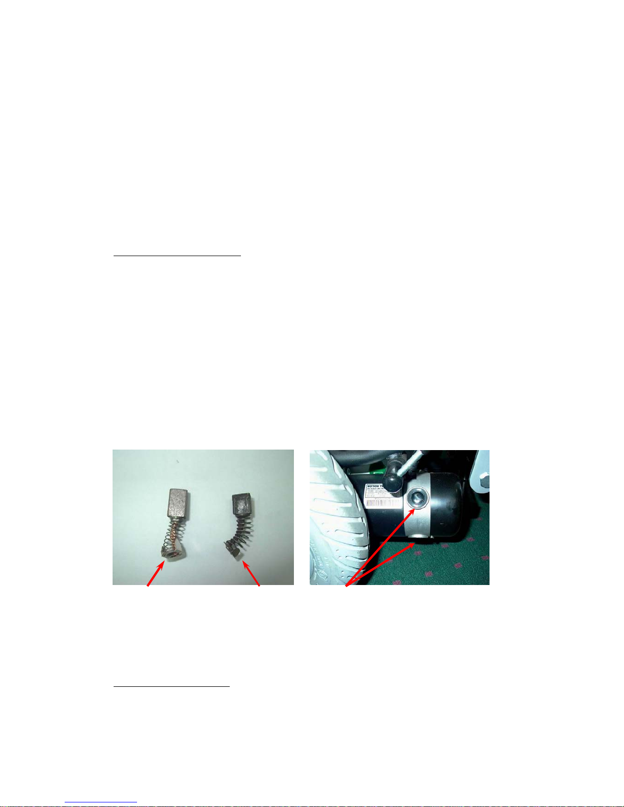
o ins ce the motor brushes:
Fig 18)
r wear. (See F ig 19)
bushes every six months, or sooner if your power wheelchair is not operating
smoothly. If inspection determines excessive wear on the brushes, they must be
replaced or motor damage will result.
rning! Failure to maintain the brush
warranty.
pect or repla
1.Unscrew the motor brush caps. (See
2.Remove the brushes.
3.Inspect the brushes fo
4.Replace the brushes if necessary.
New Motor Brush
Worn M rush
otor
ke sure that they are
PE
M Brush caps
otor B
(Fig 18) (Fig 19)
2. Inspect the state of the battery terminals every six months. Ma
not corroded and the connections are tight. Periodically apply a thin film of
petroleum jelly on the surface of terminals to guard against corrosion.
RIODICAL CHECKS
1. Make sure to keep the controller clean while protecting it from rain or water . Never
hose off your power wheelchair or place it in direct contact with water.
Page 21

2.
ave your tires replaced by
4. washed with warm water and mild soap. Occasionally check
e
5. m will benefit from simple lubrication and inspection.
se
If you get one of these error codes, contact your local dealer.
Keep wheels free from lint, hair, sand and carpet fibers.
3. V isually in spect the tire tread. If less than 1/32”, please h
your local dealer.
All upholstery can be
the seat and back for sagging, cuts, tears and replace if necessary . Do not store your
chair in damp condition as this will lead to mildew and rapid deterioration of th
upholstery parts.
All moving mechanis
Lubricate using petroleum jelly or light oil. Do not use too much oil, otherwi
small drips could stain and damage carpets and furnishings etc. Always perform a
general inspection of the tightness of all nuts and bolts.
Page 22

FLASHING LIGHTS
DIAGNOSIS AND SOLUTION
1 The battery needs charging or there is a bad connection to the
battery. Check the connections to the battery. If the connections are good, try charging the battery.
2 The left motor has a bad connection. Check the left motor
connection.
3 The left motor has a short circuit to a battery connection.
Contact your local dealer.
4 The right motor has a bad connection. Check the right motor
connection.
5 The right motor has a short circuit to a battery connection.
Contact your local dealer.
6 The power chair is being inhibited by the battery charger.
Unplug the battery charger.
7 A joystick fault is indicated. Make sure that the joystick is in th
neutral (center) position before turning on the controller.
e
8 A controller system fault is indicated. Make sure that all
connections are secure.
9 The parking brakes have a bad connection. Check the parking
brake and motor connections. Make sure the controller
connections are secure.
10 An excessive voltage has been applied to the controller. This is
Usually caused by a poor battery connection. Check the battery
connections.
Page 23

The following symptoms could indicate serious problems with your power wheel-
chair. Contact your local dealer if any of the following arises:
1. Motor noise
2. Frayed harnesses
3. Cracked or broken connectors
4. Uneven wear on any of tires
5. Jerky motion
6. Pulling to one side
7. Bent or broken wheel assemblies
8. Does not power up
9. Powers up, but does not move
Page 24

WARRANTY
Your Drive brand product is warranted to be free of defects in materials and workmanship as follows:
Chair/Scooter frame: Lifetime
Electronic Controller and drive train components: 1 year
Batteries: 6 months from time of installation
This device was built to exacting standards and carefully inspected prior to shipment. This Lifetime
Limited Warranty is an expression of our confidence in the materials and workmanship of our products
and our assurance to the consumer of years of dependable service.
In the event of a defect covered by this warranty, we will, at our option, repair or replace the device.
This warranty does not cover device fail ure due to o wner m isuse or negli gence, o r norm al wear and te ar.
The warranty does not extend to wearable components.
If you have a question about your Drive device or this warranty, please contact an authorized Drive
dealer.
WARRANTY CONDITIONS:
1. Any work or replacement part installation must be ca rried out by an authorized Drive dealer/
service agent.
2. Should your power chair require attention under this warranty, please contact an authorized
Drive dealer.
3. Any repaired or replaced parts will be covered by this warranty for the balance of the
warranty period on the power chair.
4. The above warranty conditions apply to an new power chair purchased at the full retail price.
If you are unsure whether your power chair is covered, check with an authorized Drive
dealer.
5. Under normal circumstances, no responsibility will be accepted where the power chair has
failed as a direct result of:
a. The power chair part not having been maintained in accordance with the
manufacturer’s recommendations.
b. Failure to use the manufacturer’s specified parts.
c. The power chair or part having been damaged due to neglect, accident or
improper use.
d. The power chair or part having been altered from the manufacturer’ s
specifications or repairs having been attempted before the service agent is notified.
The manufacturer reserves the right to alter without notices any weights, measurements or other
technical data shown in this manual. All figures, measurements and capacities shown in this manual are
Page 25

approximate and do not constitute specifications.
DRIVE AUTHORIZED SERVICE AGENT
NAME
ADDRESS
TELEPHONE
FAX
EMAIL
Page 26

Warranty Registration
Please type or print.
Serial # _______________________________________ Date Purchased ____/____/____
Owner Name __________________________________ __________________________
Address _________________________________________________________________
City ____________________________________ State ________ Zip ________
Additional Required Owner Information
Please indicate your understanding of your scooter by completing the following information.
________ I have read and fully understand
_______ Owner’s Manual, especially sections on operating instructions, safety guidelines,
maintenance and battery instructions.
_______ Scooter Warranty
Battery Instructions – only sealed lead acid or gel cell type batteries should be
used. Batteries must also be sealed, deep cycle, and maintenance free or battery
will hinder vehicle performance and void the warranty.
_______ My dealer has instructed me on how to operate my scooter.
Signature ______________________________Dealer Name ___________________________
Telephone (____) ________________________Dealer Phone (____)_____________________
Email Address_____________________________________________________________________
Comments:_________________________________________________________________________
___________________________________________________________________________________
___________________________________________________________________________________
___________________________________________________________________________________
___________________________________________________________________________________
___________________________________________________________________________________
_____
Page 27

W ARRANTY APPLICATION FORM
Name
Sex 口 Male 口 Female
Date of Birth
Year Month Day
Address
Model 口 SUNFIRE GLADIATOR
VIN:
VIN
Motor Serial No: Key #
Date of Purchase
Year Month Day
Purchaser Signature
10.1 VIN (VEHICLE INDIFICATION NUMBER)
To ensure the correct after sales service and warranty
service support, please write down the vehicle
identification number that is stuck on the back left-hand
side of the frame.
Model SUNFIRE GLADIATOR
VIN
Motor serial # Key #
 Loading...