

Drive Delta 1000 Assambly And Operation Manual
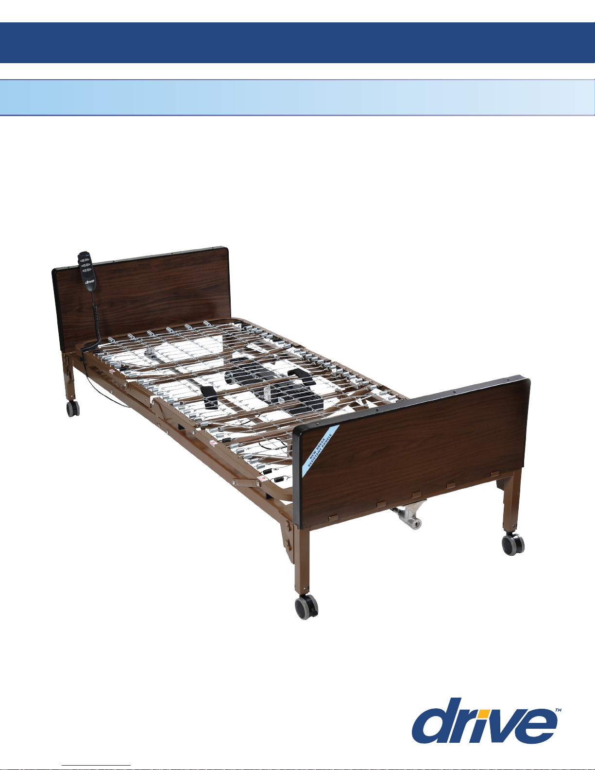
Delta 1000
Ultra Light Plus, Semi Electric Bed
Item # 15030
Owner’s Assembly And Operating Manual
1
REV3.1.14.16
2
Assembly Instructions
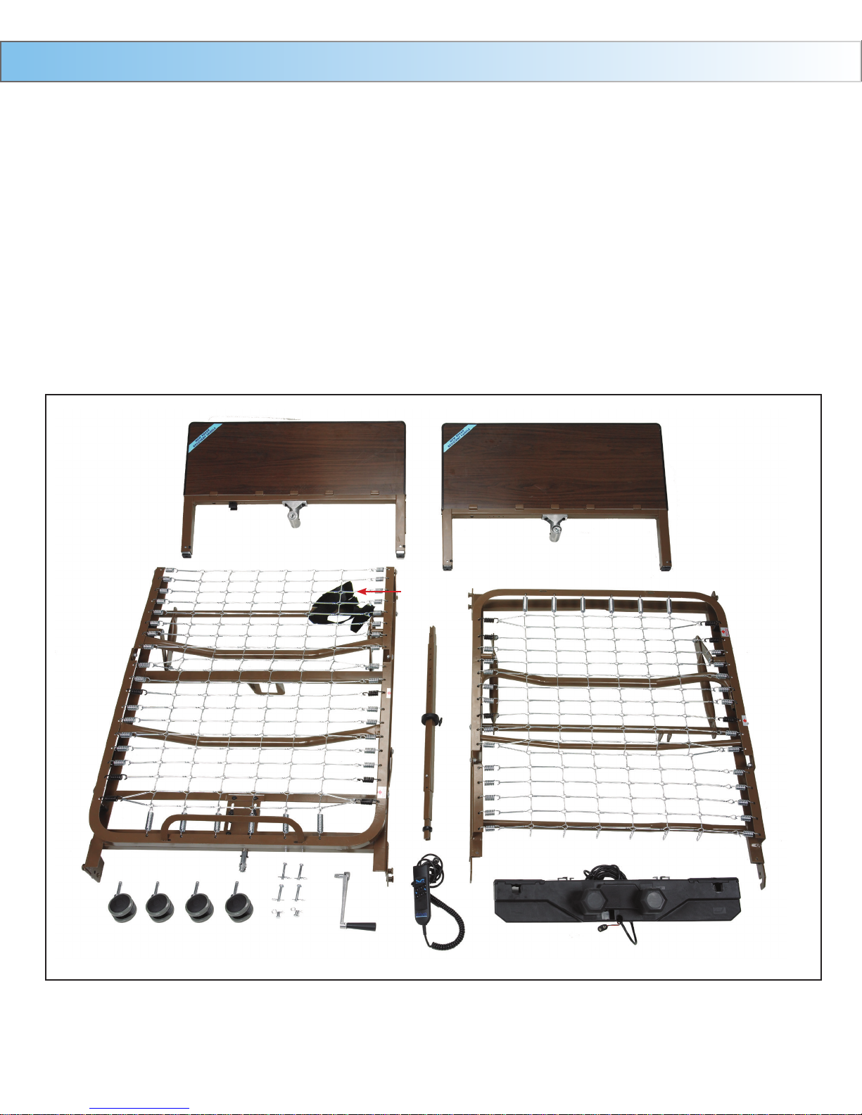
Conrm that all parts are present.
A. Foot Spring
B. Head Spring
C. Head Board
D. Foot Board
E. Hi/Low Shaft
F. Locking Pins
G. Motor
H. Hand Crank (attached to foot board for shipping)
I. Casters (4) - 2 locking, 2 non-locking
J. Spring Clips (2)
K. Hand Pendant
M. Motor Transport Straps
A
I
D
C
M
E
B
F
H
K
J
G
Assembly Instructions Cont.
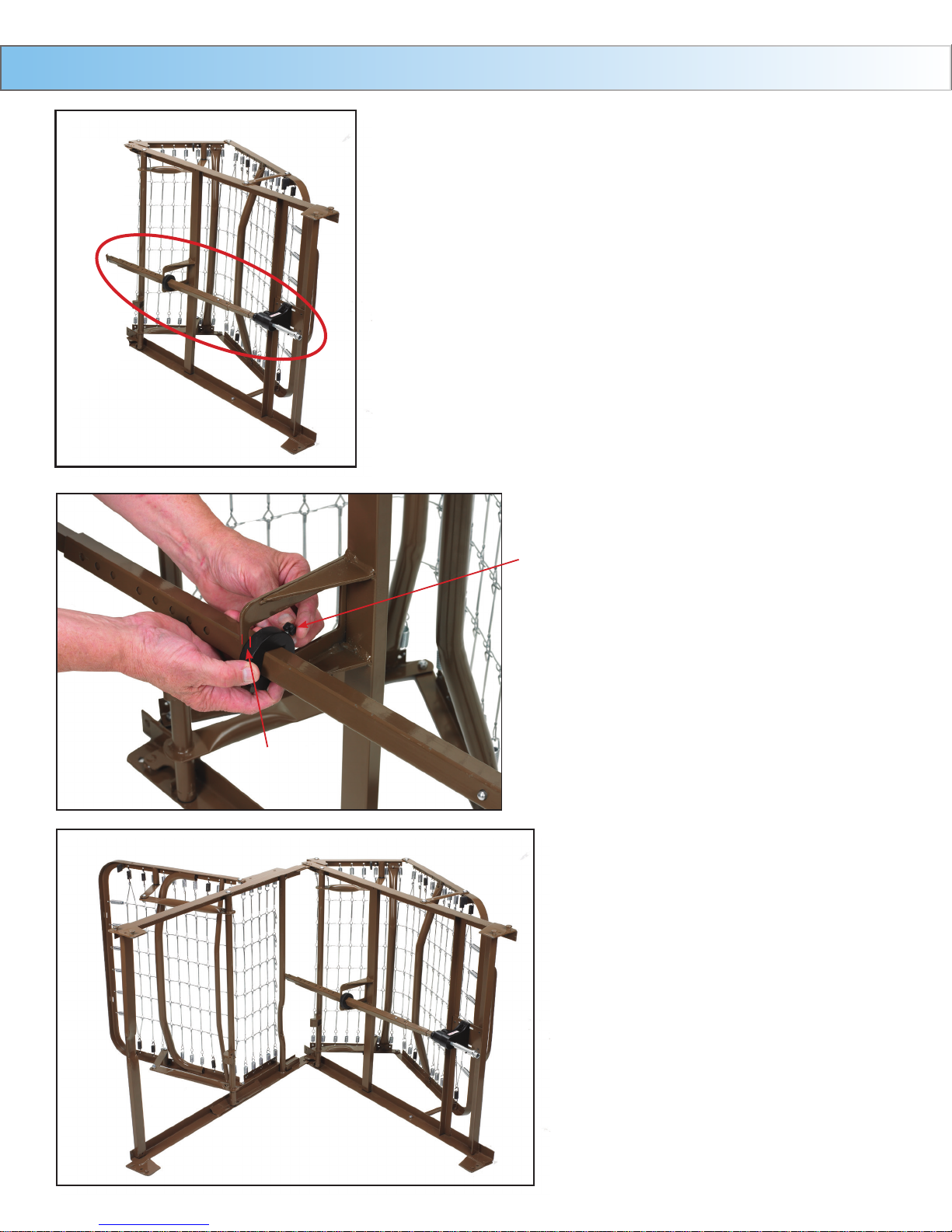
1. Install drive shaft onto foot section.
3
1/4” Gap
Thumb Screw
2. The lock collar comes pre-set from
the factory. Ensure that it is 1/4” -
1/2” away from hanger bracket. If
not, slide lock collar 1/4” from the
foot side of the hanger bracket as
shown. Tighten thumb screw.
Note: The rail is marked full or semi as
a guide.
3. Connect the head spring
by aligning with foot spring
and swinging both ends away
from each other. (Continued
on next page)
4
Assembly Instructions Cont.
Continued
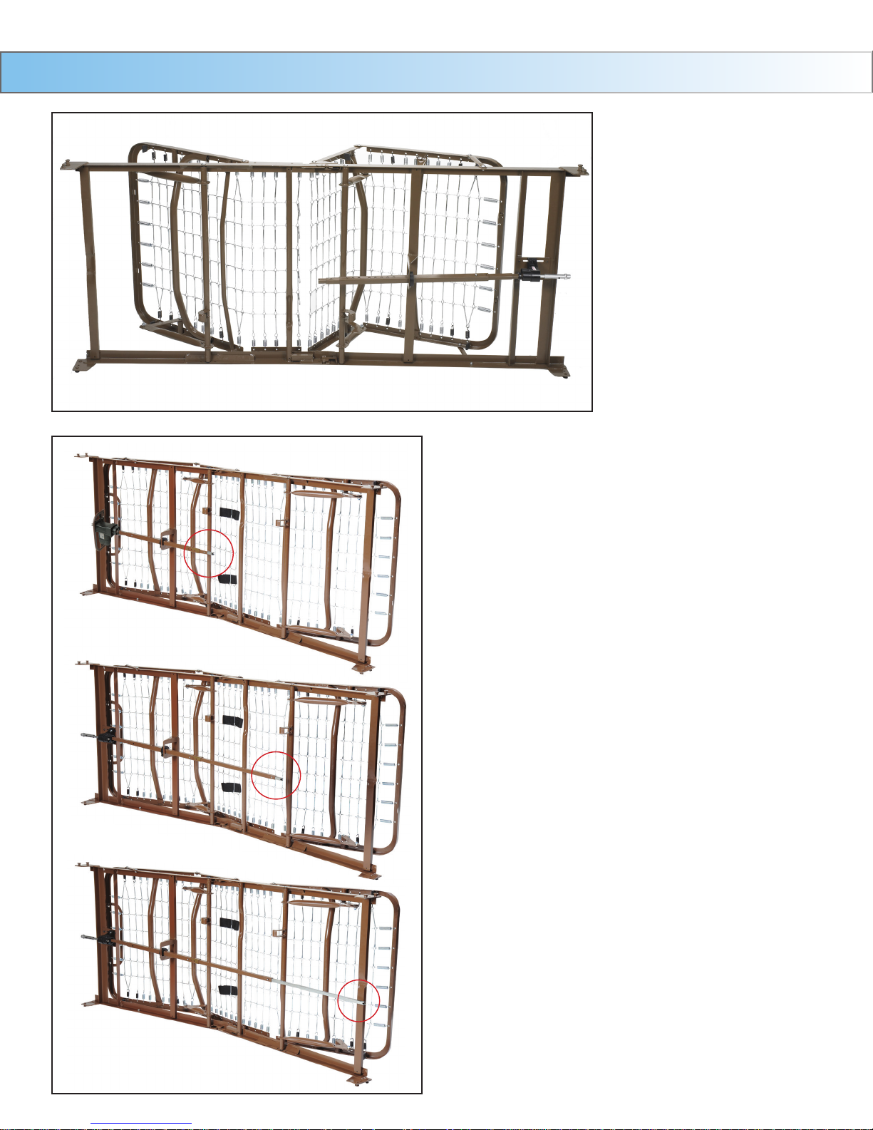
4. With bed on side extend the shaft until it
reaches the full length of bed.
a. NOTE: The shaft adjustment holes are
marked to indicate the style (semi/full) of bed
the shaft is being installed on.

Assembly Instructions Cont.
5
5. Insert lock pin through connected sleep
surface and secure with spring clip.
5A. Connect head section and foot section
by squeezing together and attaching
with spring links. Pull up the head
section and foot section to release
tension between the springs.
6
Assembly Instructions Cont.
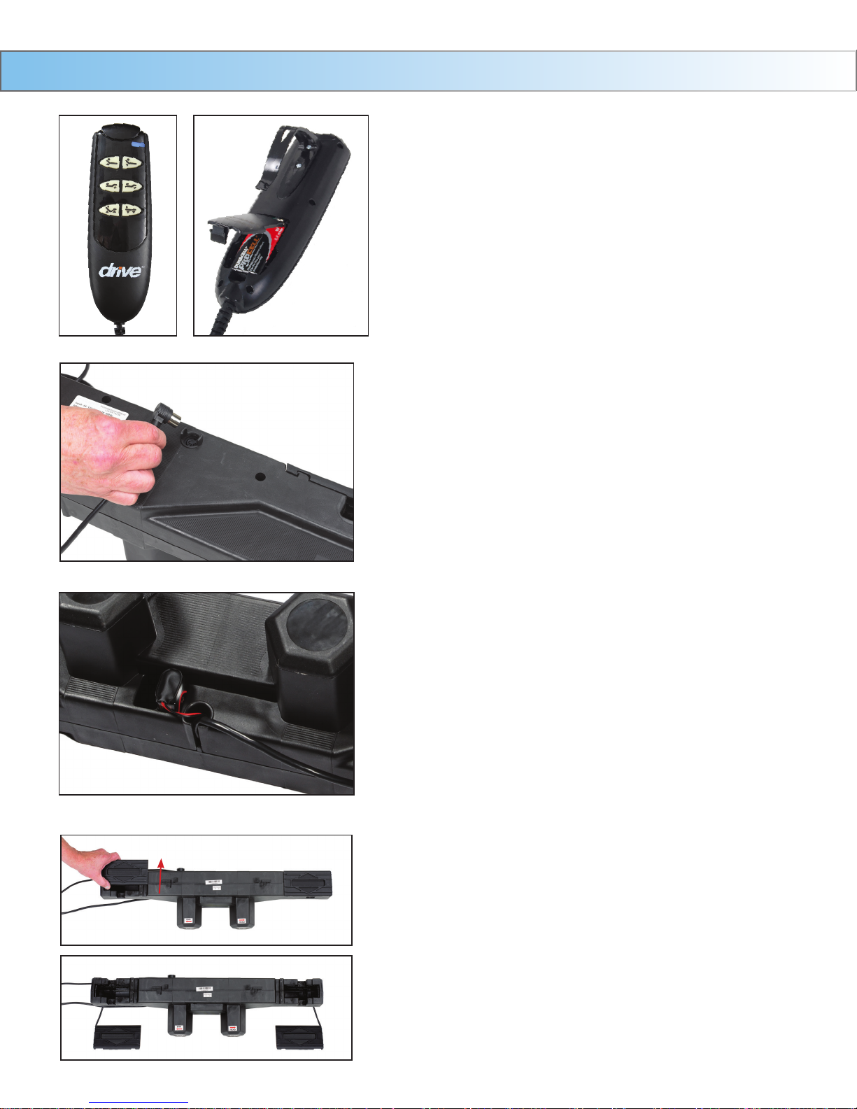
HAND CONTROL
The
Delta bed comes with a hand control that will
illuminate when the bed is plugged into a grounded or
polarized wall outlet, or with 9V battery (sold separately)
installed in the hand control. The hand control will
illuminate as long as the wall or battery has power. With
this battery installed, the motor can be operated to return
the sleep surface to the horizontal position in the event
of a power failure.
NOTE: Before installing motor, plug hand
pendant cable into motor as shown
6. Connect the 9V battery (sold separately) to the
battery clip on the motor. It is stored in the recess
under the motor cover. With this battery installed,
the motor can be operated to return the sleep
surface to the horizontal position in the event of a
power failure.
7. To install motor, remove locking caps on top of
the motor.
Assembly Instructions Cont.
There are two methods for the installation of
the motor
Method A
The motor is installed on the bed frame when the frame is standing
on its side.
7
Installation instructions can be found on pages 8-9.
Method B
The motor is installed from underneath the bed frame
(horizontal to the ground)
Installation instructions can be found on pages 10-11.
8
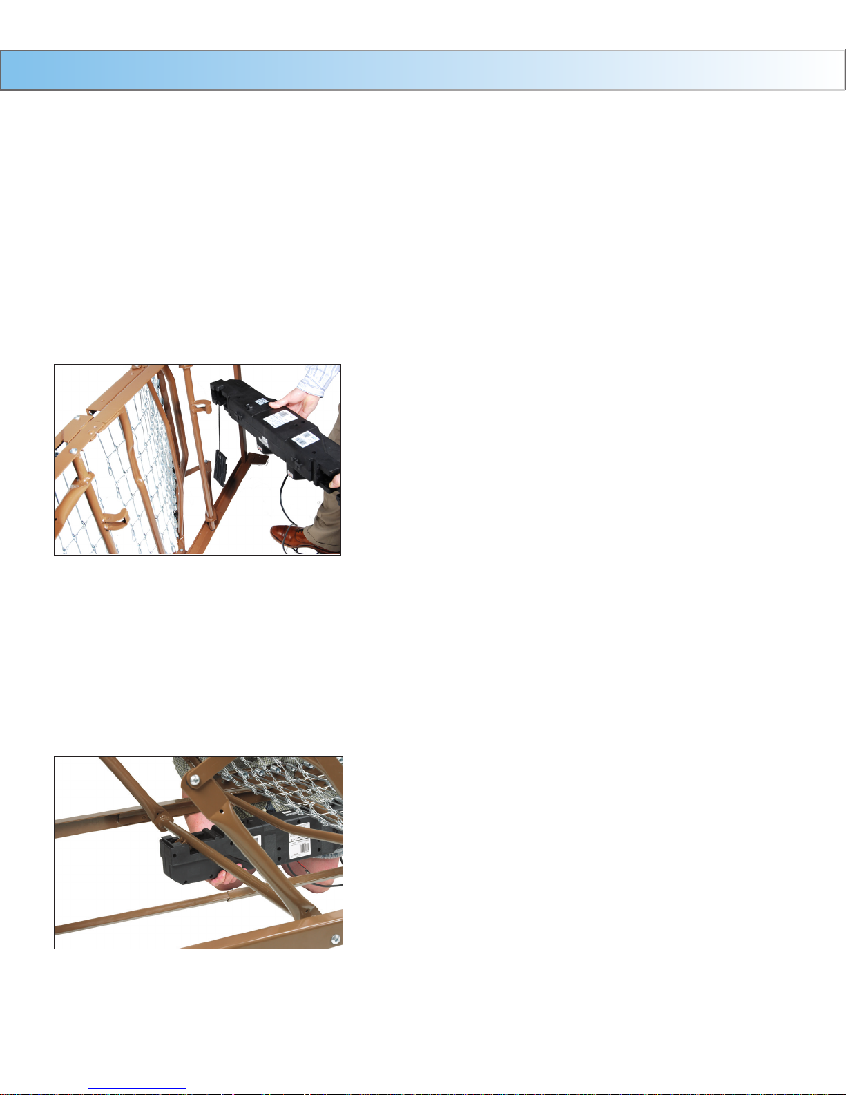
Assembly Instructions Cont.
Method A
Installation of the motor when bed frame is on its side
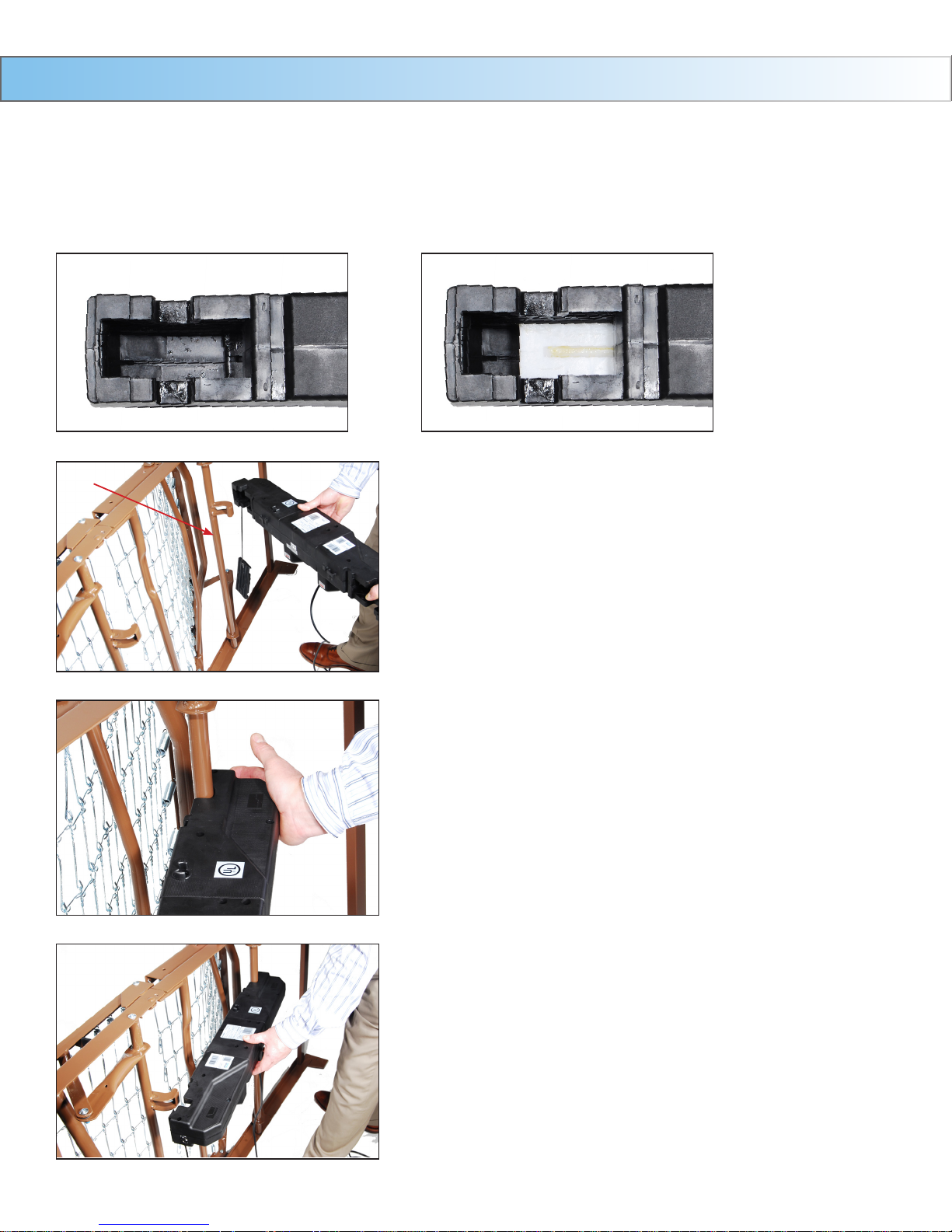
A1. Prior to installation, make sure that the 2 white motor blocks are in the retracted position.
CORRECT INCORRECT
Actuator Bar
A2. Align the opening on the head end of the
motor with the ange on the head section of
the bed and insert the ange into the motor
compartment.
A3. With the palm of your hand, snap the motor
ush to the actuator bar.
A4. Align the opening on the foot end of the
motor with the ange on the foot section of
the bed and insert the ange into the motor
compartment.
Assembly Instructions Cont.
Method A (Continued)
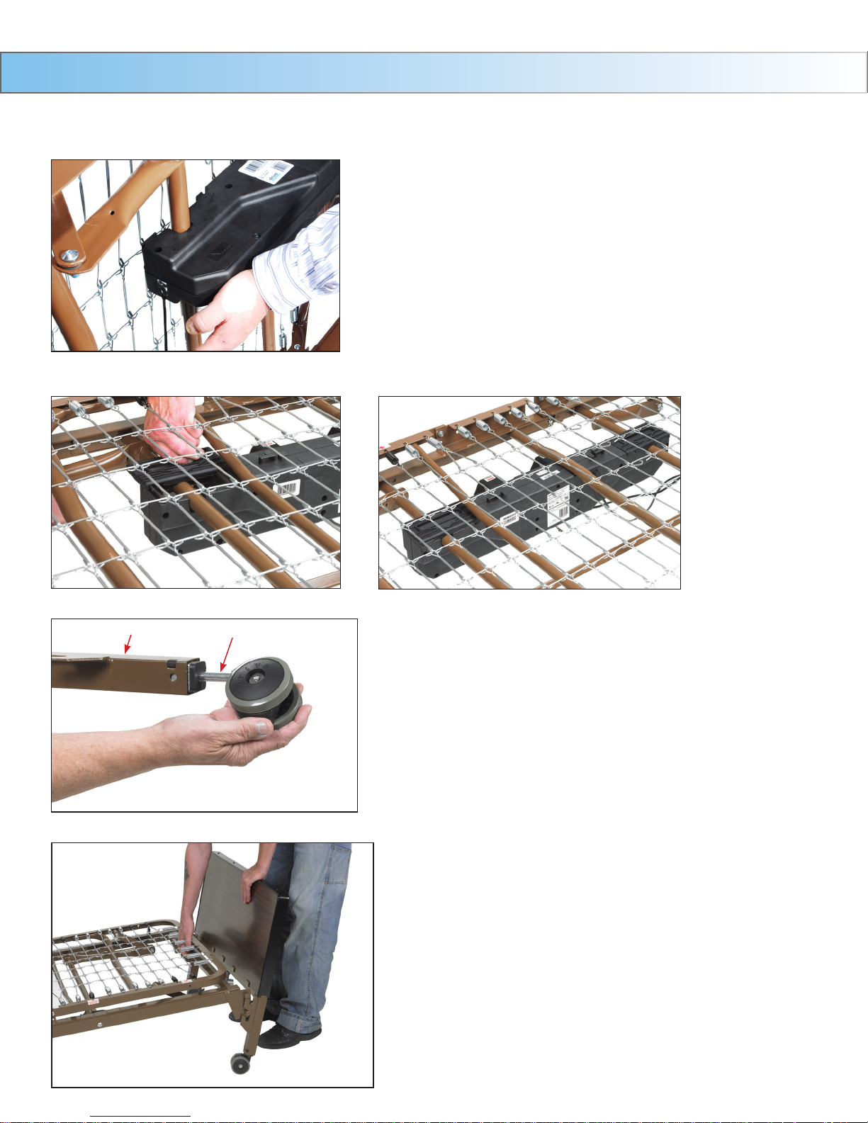
A5. With the palm of your hand, snap the motor
ush to the actuator bar.
A6. After the motor is installed, slide locking covers back on motor.
9
Leg Receptacle
Stem
A7. Install the casters by inserting the
stem of the caster into the leg
receptacle. It is recommended to
install 1 locking caster and 1 non locking caster on each bed end.
The locking casters should be
installed diagonally from each other.
A8. Attach the foot board and head board
as shown.
a. NOTE: The head section is higher than
the foot section. However, they are
interchangeable with each other, with all
other Drive and other manufacturers
head and foot boards.
End Method A
Go To Page 12, Step 8
 Loading...