

Page 1
PortWashington,NY11050
PDF created with FinePrint pdfFactory trial version http://www.pdffactory.com
Page 2

INDEX
Chapter Contents Page
Index………… ….....................… ……………………………….1
1. Introduction.………………………………………………………2
2. Cautions .……………………………………………………….…2
3. Warnings.……………………………………………………….…3
4. General Description.……………………………………….….…4
5. Construction...…………………………………………………...5
6. Technical Specifications..……………………………………….6
7. Replaceable Parts...…………………………………………..….7
8. Accessories....…………………………………………………….7
9. Graphic Symbols...……………………………………………....8
10. Parameter Controls............……………………………….…....9
11. Attachment of Electrodes Lead Wires .……………………..11
12. Lead Wire Maintenance .……………………………………....11
13. Electrode Options……………………………………………....11
14. Electrode Placement.....………………………………………..12
15. Tips For Skin Care....…………………………………………..13
16. Application of Re-usable Self Adhesive Electrodes .……...14
17. Adjusting the Controls....……………………………………...15
18. Battery Information...…………………………………………..19
19. Maintenance, Transportation and Storage of DIGITAL
EMS Device.........................................................................21
20. Safety Control.....…………………………………………….....21
21. Malfunctions …………………………………………………. ..22
22. Conformity to Safety Standards…….………………………..22
23. Warranty/ Manufacturer/ Representative in the EU.....…...23
PDF created with FinePrint pdfFactory trial version http://www.pdffactory.com
1
Page 3
Chapter 1 : INTRODUCTION
EXPLANATION OF DIGITAL EMS
Electrical Muscle Stimulation is an internationally accepted and proven way of treating muscular injuries. It works by sending electronic pulses to the muscle needing
treatment; this causes the muscle to exercise passively.
It is a product derived from the square waveform, originally invented by John Faraday in 1831. Through the square wave pattern it is able to work directly on muscle
motor neurons. DIGITAL EMS has low frequency and this in conjunction with the
square wave pattern allows direct work on muscle groupings. This is being widely
used in hospitals and sports clinics for the treatment of muscular injuries and for
the re-education of paralyzed muscles, to prevent atrophy in affected muscles
and improving muscle tone and blood circulation.
HOW DIGITAL EMS WORKS
DIGITAL EMS is intended to be used to increase blood circulation and loosens
tight and knotted fibers, stimulates muscle growth and also reduces stiffness in
muscle joints. The DIGITAL EMS units send comfortable impulses through the
skin that stimulate the nerves in the treatment area. When the muscle receives
this signal it contracts as if the brain has sent the signal itself. As the signal strength
increases, the muscle flexes as in physical exercise. Then when the pulse ceases,
the muscle relaxes and the cycle starts over again, (Stimulation, Contraction and
Relaxation.)
Chapter 2 : CAUTIONS
1.Precautions:
Isolated cases of skin irritation may occur at the site of electrode placement
following logn-term application. Effectiveness is highly dependent upon patient
selection by a person qualified in the management of pain patients.
2.Contradictions:
TENS devices can affect the operation of demand type cardiac pacemakers.
TENS is not recommended for patients with known heart disease without physical evaluation of risk. Do not use TENS on the carotid sinus(neck) region. Do no
apply TENS for undiagnosed pain syndromes until etiology is established. Do
not stimulate on the site that may cause current to flow transcerebrally(through
the head).
3.Adverse Reactions
Possible allergic to gel, skin irritation and electrode burn are potential adverse
reactions.
4.Read operation manual before use of EMS.
5.We emphasize that patient with an implanted electronic device (for example, a
pacemaker) should not undergo EMS treatment without first consulting a doctor.
The same applies to patients with any metallic implants.
6.If EMS therapy becomes ineffective or unpleasant, stimulation should be dis
continued until its use is reevaluated by the physician or therapist.
7.Avoid adjusting controls while operating machinery or vehicles.
8.Turn the T.E.N.S. off before applying or removing electrodes.
9.AGF-3X T.E.N.S. devices have no AP/APG protection.
Do not use it in the presence of explosive atmosphere and flammable mixture.
Chapter 3 : WARNINGS
1.Caution should be used in applying EMS to patients suspected of having heart
disease. Further clinical data is needed to show there are no adverse results.
2.The safety of EMS devices for use during pregnancy or birth has not been
established.
Do not use EMS during pregnancy.
3.EMS is not effective for pain of central origin. (This includes headache.)
4.EMS devices should be used only under the continued supervision of a physician.
5.EMS devices have no curative value.
6.EMS is a symptomatic treatment and as such suppresses the sensation of pain
which would otherwise serve as a protective mechanism.
7.Electronic monitoring equipment (such as ECG monitors and ECG alarms)
2 3
PDF created with FinePrint pdfFactory trial version http://www.pdffactory.com
Page 4
may not operate properly when EMS stimulation is in use.
8. There should be a prominently placed statement warning that stimulus delivered by this device may be sufficient to cause electrocution. Electrical current
of this magnitude must not flow through the throax because it may cause a
cardiac arrhythmia.
9. Do not place electrodes on the front of the throat as spasm of the Laryngeal
and Pharyngeal muscle may occur.
10. Care should be taken so that when operating potentially dangerous machinery
the stimulator controls are not changed abruptly.
6. Electrodes should not be placed over the eyes, in the mouth, or internally.
11. Keep this device out of the reach of children.
12. Caution: Federal law restricts this device to sale by or on the order of a physi
cian
Chapter 4 : GENERAL DESCRIPTION
The AGF-6X DIGITAL EMS is a battery operated pulse generator that sends
electrical impulses through electrodes to the body and reaches the underlying
nerves or muscle group. The device is provided with two controllable output
channels, each independent of each other. An electrode pair can be connected to each output channel.
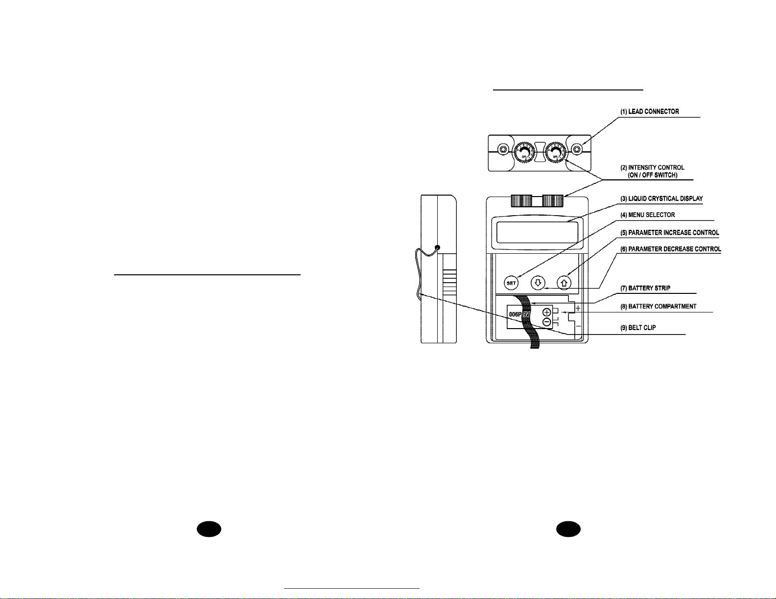
Chapter 5 : CONSTRUCTION
The electronics of the AGF-6X DIGITAL EMS create electrical impulses whose
Intensity, Pulse Width, Pulse Rate, Contraction, Relaxation and Ramp may be
altered with the switches. Press buttons are very easy to use and the slide
cover prevents accidental changes in the setting.
4 5
PDF created with FinePrint pdfFactory trial version http://www.pdffactory.com
Page 5

Chapter 6 : TECHNICAL SPECIFICATION
Chapter 7 : REPLACABLE PARTS
The technical specification details of AGF-6X DIGITAL DIGITAL EMS are as
follows.
MECHANISM TECHNICAL DESCRIPTION
01. Channel Dual, isolated between channels.
02. Intensity Control Adjustable 0-90mA, Max output 90mA peak to
peak (17.8mA rms) into 500ohm load each
channel.
03. Wave Form Asymmetrical Bi-Phase Square Pulse
04. Voltage Adjustable 0-45V, Max output 45V peak to peak
(8.9V rms) into 500ohm load each channel.
05. Power Supply One 9V battery.
06. Size 10cm (L) x 6 cm(W) x 2.1cm(H)
07. Weight 120 grams with battery
08. Pulse Rate Adjustable, from 1 Hz to 150 Hz
09. Pulse Width Adjustable, from 30 uS to 260 uS
10. Contraction Time Adjustable from 1 - 30 seconds
11. Relaxation Time Adjustable from 1 - 30 seconds
12. Ramp Time Adjustable from 1 - 6 seconds
13. Timer Adjustable : 1 - 60 minutes.
14. Max. Charge per pulse 20 micro – coulombs
15. Battery Life Approximately 25 hours at nominal settings
The replaceable parts and accessories of DIGITAL EMS devices are as given
below –
Except leads, electrodes and battery, battery case cover, please do not try to replace the other parts of a device.
PARTS
01 ELECTRODES LEADS
02 ELECTRODES
03 9V BATTERY ,TYPE 6F22
04 BELT CLIP
05 BATTERY CASE COVER
06 LEAD CONNECTOR
07 MAIN PCB
08 INTENSITY KNOB
Chapter 8 : ACCESSORIES
Each set AGF-6X DIGITAL EMS are completed with standard accessories and
standard label as given below
I.Accessories
REF. NO. PRODUCT Q’TY
AGF-101 40 X 40 MM Adhesive Electrodes 4 pieces
AGF-111N Electrodes Leads 2 pieces
9 V Battery 1 piece
Instruction Manual 1 piece
Carrying Case 1 piece
6 7
PDF created with FinePrint pdfFactory trial version http://www.pdffactory.com
Page 6

II.LABEL
The label attached to the back of
devicecontains important message about
this device- model, serial number, supply voltage, the name of manufacturer, CE
number and classification. Please do not remove.
Chapter 9 : GRAPHIC SYMBOLS
1. Note Operating Instructions
Chapter 10 : PARAMETER CONTROLS
PULSE DURATION
Wider pulse duration settings will deliver stronger stimulation for any given intensity setting. As mentioned in the Controls section, by using a combination of
intensity and pulse duration, it is felt that various pulse widths are capable of stimulating different muscles groups.
The wider pulse duration is needed to recruit motor fibres, whereas the narrow
pulse duration is used on the more sensory fibres.
2. Degree of Electrical Protection BF
3. Do not insert the plug into AC power supply socket
4. Direct Current (DC power source)
5. Pulse Rate
6. Pulse Width
7. Timer
8. Parameter Increase
9. Parameter Decrease
PULSE RATE
The Pulse Rate (hertz or pulses per second) chosen depends greatly upon the
type of electrode placement given to the patient.
When using contiguous and dermatome electrode placements (i.e. stimulating
directly through the area of pain or localized enervation), a quick pulse rate (setting
greater than 80Hz on the Pulse Rate Control) is desired. The patient should not
perceive individual pulses but rather have the sensation of steady continuous
stimulation.
When using point treatments, it has been suggested that slow pulses be utilized
(less than 10Hz). With this setting the patient should be able to slightly perceive
individual pulses.
When using multiple electrode placement strategies, such as combinations of
point and contiguous electrode placements, the quicker pulse rates are suggested.
Despite above recommendations, these individual patients may require slight variations of the above settings, according to the nature of their condition.
INTENSITY
Each patient responds differently to different levels of intensity, due to varying degrees of tissue resistance, enervation, skin thickness, etc. Intensity instructions
are therefore limited to the following settings:
8 9
PDF created with FinePrint pdfFactory trial version http://www.pdffactory.com
Page 7

Perception – The intensity is increased so that the patient can feel the
stimulation, but there is not any muscular contraction.
Slight Contraction – Intensity is increased to a barely visible muscular contraction that is not strong enough to move a joint. When using low pulse rate
settings, this will show as individual twitches. At higher pulse rates there will
simply be increased muscle tension.
Strong muscular contraction is may be useful in spastic muscle group. The DIGITAL EMS can be used in the circumstances to quickly break the spasm. Use a
quick pulse rate, wide pulse duration and set the intensity to visible contraction
(still within patient tolerance). Twenty or thirty minutes of such a tetanized muscular contraction will generally break the spasm. In all cases, if the patient complains
that the stimulation is uncomfortable, reduce intensity and cease stimulation.
CONTRACTION / RELAXATION
Chapter 11 : ATTACHMENT OF ELECTRODE LEAD WIRES
The wires provided with the system insert into the jack sockets
located on top of the device. Holding the insulated portion of the
connector, push the plug end of
the wire into one of the jacks (see
drawing); one or two sets of wires
may be used.
After connecting the wires to the
stimulator, attach each wire to an electrode. Use care when you plug and
unplug the wires. Jerking the wire instead of holding the insulated connector bodymay cause wire breakage.
The contraction time and relaxation time of DIGITAL EMS is adjustable.
Stimulation will continue at the setting contraction time and cease also at the setting relaxation time. Then the cycle starts over again – Stimulation, Contraction
and Relaxation.
RAMP
In order to achieve a comfortable exercise and avoid startle because of electrical
shock, each contraction course may be ramped so that the signal comes on gradually and smoothly. The intensity of electrical current will reach the setting level
within the Ramp time, however, it can not reach the expected level if the contraction time is less than the ramp time.
TIME DURATION
DIGITAL EMS units are typically operated for long periods of time, with a minimum
of 20 – 30 minutes. However, the time is varied subject to the treatment required.
Please consult your physician before use of DIGITAL EMS.
10 11
CAUTION
Do not insert the plug of the patient lead wire into the AC power supply socket.
Chapter 12: LEAD WIRE MAINTENANCE
Clean the wires by wiping with a damp cloth. Coating them lightly with talcum
powder will reduce tangling and prolong life.
Chapter 13 : ELECTRODE OPTIONS
Your clinician will decide which type of electrode is best for your condition. Follow
application procedures outlined in electrode packing, to maintain stimulation and
prevent skin irritation. Use of legally marketed adhesive electrodes is
recommended.
PDF created with FinePrint pdfFactory trial version http://www.pdffactory.com
Page 8

Chapter 14 : ELECTRODE PLACEMENT
MULTIPLE PLACEMENT STRATEGIES
The placement of electrodes can be one of the most important parameters in
achieving success with DIGITAL EMS therapy. Of utmost importance is the willingness of the clinician to try the various styles of electrode placement to find
which method best fits the needs of the individual patient.
Every patient responds to electrical stimulation differently and their needs may
vary from the conventional settings suggested here. If the initial results are not
positive, feel free to experiment. Once an acceptable placement has been achieved,
mark down the electrodes sites and the settings on the patient’s Reference sheet
of this manual, so the patient can easily continue treatment at home.
CONTIGUOUS PLACEMENT
This is the most common placement technique. It involves placing the electrodes
alongside the affected muscles or muscle groups, in such a way as to direct the
flow of current through or around the area.
DERMATOMES, MYOTOMES AND SCLEROTOMES
These are the regions of the body enervated by one spinal nerve. Electrode placement involves both stimulating across the similarly enervated area and/or placing
one electrode (or set of electrodes) at the affected site and another electrode (set)
at the point where the nerve root joins the spinal cord.
MOTOR, TRIGGER AND ACUPUNCTURE POINTS
While these points of high tissue conductivity can differ in location and in theory of
use, their use as an electrode site is identical. The easiest technique involves
placing one pad directly over the point and completing the circuit by placing the
second pad on some area on the affected side. This second electrode site
can be within a nerve zone, or a master point located between the thumb and
the forefinger on the dorsal web area between the two metacarpal bones.
Because the DIGITAL EMS has two independently operated channels, the clinician may take advantage of concurrent pad placement strategies.
For example, it is possible to use two different electrode placement strategies at
the same time. One channel can be used to directly stimulate the pain site in a
contiguous manner; the other channel can be placed along the involved dermatome
or utilized for point therapy.
Chapter 15 : TIPS FOR SKIN CARE
To avoid skin irritation, especially if you have sensitive skin, follow these suggestions:
1.Wash the area of skin where you will be placing the electrodes, using mild soap
and water before applying electrodes, and after taking them off. Be sure to rinse
soap off thoroughly and dry skin well.
2.Excess hair may be clipped with scissors; do not shave stimulation area.
3.Wipe the area with the skin preparation your clinician has recommended. Let
this dry. Apply electrodes as directed.
4.Many skin problems EMS arise from the “pulling stress” from adhesive patches
that are excessively stretched across the skin during application. To prevent
this, apply electrodes from centre outward; avoid stretching over the skin.
5.To minimize “pulling stress”, tape extra lengths of lead wires to the skin in a loop
to prevent tugging on electrodes.
6.When removing electrodes, always remove by pulling in the direction of hair
growth.
7. It may be helpful to rub skin lotion on electrode placement area when not wear
ing electrodes.
8.Never apply electrodes over irritated or broken skin.
12 13
PDF created with FinePrint pdfFactory trial version http://www.pdffactory.com
Page 9

Chapter 16 : APPLICATION OF RE-USABLE SELF
ADHESIVE ELECTRODES
Application
1.Clean and dry the skin at the prescribed area thoroughly with soap and water
prior to application of electrodes.
2.Insert the lead wire into the pin connector n the pre-wired electrodes.
3.Remove the electrodes from the protective liner and apply the electrodes firmly
to the treatment site.
Removal
1.Lift at the edge of electrodes and peel; do not pull on the lead wires because it
may damage the electrodes.
2.Place the electrodes on the liner and remove the lead wire by twisting and pull
ing at the same time.
Care and Storage
Important
1.Do not apply to broken skin.
2.The electrodes should be discarded when they are no longer adhering.
3.The electrodes are intended for single patient use only.
4.If irritation occurs, discontinue use and consult your clinician.
5.Read the instruction for use of self-adhesive electrodes before application.
Chapter 17 : ADJUSTING THE CONTROLS
1.Slide Cover:
A slide-on panel covers the controls for Contraction Time,
Relaxation Time, Ramp Time, Pulse Width, and Pulse Rate.
Your medical professional may wish to set these controls
for you and request that you leave the cover in place.
2.Power On/Off Switch and Intensity Controls:
If both controls are in the off-position, the device is switched
off.
By turning the controls clockwise, the appropriate channel
is switched on and the indicator of power (a dot) will reveal
on the LCD.
The current strength of the impulses transmitted to the electrodes increases
further when the control is turned clockwise.
To reduce the current strength or switch the device off, turn the control counter
clockwise to the required setting or off-position, respectively.
1.Between uses, store the electrodes in the resealed bag in a cool dry place.
2.It may be helpful to improve repeated application by spreading a few drops of
cold water over the adhesive and turn the surface up to air dry. Over Saturation
with water will reduce the adhesive properties.
14 15
PDF created with FinePrint pdfFactory trial version http://www.pdffactory.com
Page 10

4.Lead Connector
Connection of the electrodes is made with two-lead connector. The device must
be switched off before connecting the cables. Both intensity controls must be at
the Off position. Electrodes must be pressed firmly on the skin.
5.Function Selector
Expose the controls by sliding front cover down from top of unit. This button
Controlling the menu on the LCD. When the button is pressed, it can change
menu from contraction time, relaxation time, ramp time, pulse rate, pulse width
to timer.
The parameter of each function can be adjusted when it is revealed on the menu.
6.Parameter Increase Control
This button controlling the increase of parameter. When pressing this button,
the parameter will increase. Press the button until the value desired is reached.
8. Function Indicator
The drawing on the top of LCD showing the function that is working.
Each part of the drawing represents one function of the course.
Ramp Up
Contraction
Ramp Down
Relaxation
The defined area will flash when the device is working on that function.
9. Step to Set Parameter
The parameter of a treatment course can be adjusted according to the following
steps.
Press “set” button to select the function you wish to set a value.
a.Turn on the Intensity
After the electrodes are placed firmly on skin and the lead wires are plugged in
the socket of device, turn the on/off control clockwise. The menu will reveal on
LCD. Notice the indication of power and function on the LCD.
7.Parameter Decrease Control
This button controlling the decrease of parameter. When pressing this
button, the parameter will decrease. Press the button until the value desired
is reached.
16 17
PDF created with FinePrint pdfFactory trial version http://www.pdffactory.com
Page 11

b.Set Contraction Time
The contraction time controls the time of stimulation. By pressing parameter
controls, the contraction time can be pre-set. The range is adjustable from 1
second to 30 seconds.
c.Set Relaxation Time
The relaxation time determines the time of relaxation. The stimulation ceases at
setting relaxation time and then re-start in a cycle pattern. The relaxation time of
both channels is changed by pressing the parameter controls. The range of it is
adjustable from 1 second to 45 seconds.
d.Set Ramp Time
This ramp time controlling the time of output current that increase from 0 to the
setting level, and from the setting value to 0. When the ramp time is set, each
contraction may be ramped in order that signals come on and come off gradually and smoothly. The ramp time is adjustable from 1 to 8 seconds by pressing
the parameter controls.
e.Set Pulse Rate
The pulse rate determines how many electrical impulses are applied through
the skin each second. By pressing the parameter controls, the number of current impulses per second (Hz) for both channels can be continually adjusted.
The pulse rate is adjustable from 1 Hz to 150 Hz. Unless otherwise instructed,
turn the pulse rate control to the 70-120 Hz range.
f. Set Pulse Width
The pulse width determines the length of time. Each electrical signal is applied through the skin, which controls the strength and sensation of the
stimulation. The pulse width is adjustable from 2 to 250 uS. Press the buttons until the desired value is reached.
g. Set Timer
The treatment time is adjustable from 1 to 60 minutes.
10.Check/Replace the Battery:
Over time, in order to ensure the functional safety of DIGITAL EMS,
changing the battery is necessary.
1.Make sure that both intensity controls are
switched to off- position.
2.Slide the battery compartment cover and remove.
3.Remove the battery from the compartment.
4.Insert the battery into the compartment. Note the
polarity indicated on the battery and in the
compartment.
5.Replace the battery compartment cover and slide
to close
Chapter 18 : BATTERY INFORMATION
AGF-6X DIGITAL EMS can be used with 6F22 rechargeable battery when
necessary. If you use rechargeable batteries, please follow the instructions.
18 19
PDF created with FinePrint pdfFactory trial version http://www.pdffactory.com
Page 12

RECHARGEABLE BATTERIES:
Prior to the use of a new unit, the rechargeable battery should be charged
according to the battery manufacturer’s instructions. Before using the battery
charger, read all instructions and cautionary markings on the battery and in
this instruction manual.
After being stored for 60 days or more, the batteries may lose their charge. After
long periods of storage, batteries should be charged prior to use.
BATTERY CHARGING
(1)Plug the charger into any working 110 or 220/240v mains electrical outlet. The
use of any attachment not supplied with the charger may result in the risk of
fire, electric shock, or injury to persons.
(2)Follow the battery manufacturer’s instructions for charging time.
(3)After the battery manufacturer’s recommended charging time has been
completed, unplug the charger and remove the battery.
(4)Batteries should always be stored in a fully charged state.
To ensure optimum battery performance, follow these guidelines:
(a)Although overcharging the batteries for up to 24 hours will not damage them,
repeated overcharging may decrease useful battery life.
(b)Always store batteries in their charged condition. After a battery has been
discharged, recharge it as soon as possible. If the battery is stored more than
60 days, it may need to be recharged.
(c)Do not short the terminals of the battery. This will cause the battery to get hot
and can cause permanent damage. Avoid storing the batteries in your pocket
or purse where the terminals may accidentally come into contact with coins,
keys or any metal objects.
(d)WARNINGS:
1.Do not attempt to charge any other types of batteries in your charger, other
than the nickel-cadmium rechargeable batteries. Other types of batteries
may leak or burst.
2.Do not incinerate the rechargeable battery as it may explode!
Chapter 19: MAINTENANCE, TRANSPORTATION
AND STORAGE OF DIGITAL EMS DEVICE
1.Non-flammable cleaning solution is suitable for cleaning the device.
Note: Do not smoke or work with open lights (for example, candles, etc.)
when working with flammable liquids.
2.Stains and spots can be removed with a cleaning agent.
3.Do not submerge the device in liquids or expose it to large amounts of water.
4.Return the device to the carrying box with sponge foam to ensure that the unit
is well-protected before transportation.
5.If the device is not to be used for a long period of time, remove the batteries
fromthe battery compartment (acid may leak from used batteries and dam
age the device). Put the device and accessories in carrying box and keep it
in cool dry place.
6.The packed DIGITAL EMS device should be stored and transported under
the temperature range of -20°C ~ +60°C, relative humidity 20%~ 95%,
Aatmosphere pressure 500hPa~1060hPa.
Chapter 20: SAFETY-TECHNICAL CONTROLS
For safety reasons, check your AGF-6X DIGITAL EMS each week based on the
following checklist.
1.Check the device for external damage.
- deformation of the housing.
- damaged or defective output sockets.
2.Check the device for defective operating elements.
- legibility of inscriptions and labels.
- make sure the inscriptions and labels are not distorted.
3.Check LCD
- Parameters must be visible on the CLD.
4.Check the usability of accessories.
- patient cable undamaged.
- electrodes undamaged.
Please consult your distributor if there are any problems EMS with device and
accessories.
20 21
PDF created with FinePrint pdfFactory trial version http://www.pdffactory.com
Page 13

Chapter 21 MALFUNCTIONS
Should any malfunctions occur while using the DIGITAL EMS, check
- whether the controls or parameters are set to the appropriate form of therapy.
Adjust the control correctly.
- whether the cable is correctly connected to the device. The cables should be
inserted completely into the sockets.
- whether the LCD reveal the menu. If necessary, insert a new battery.
- for possible damage to the cable. Change the cable if any damage is detected.
* If there is any other problem, please return the device to your distributor. Do
not try to repair a defective device.
Chapter 22 Conformity to Safety Standards
All AGF-6X Digital EMS models carry a warranty of one year from the date
of delivery. The warranty applies to the stimulator only and covers both parts
and labour relating thereto.
The warranty does not apply to damage resulting from failure to follow the
operating instructions, accidents, abuse, alteration or disassembly by unauthorized personnel.
Manufacturer:
Drive Medical Design & Manufacturing,
99 Seaview Boulevard
Port Washington, NY 11050
Phone # : 516-998-4600
STATEMENT OF EMC
The AGF-6X Digital EMS devices are in compliance with IEC 60601-1-2: 1993.
CONFORMITY TO MDD REQUIREMENTS
The AGF-6X Digital EMS d evices are in com pl ia nce with IEC60601-1 s afety
standard and FDA 510K standards.
Chapter 23 : WARRANTY
22 23
Edition : V1.2
Printed in July , 2005
PDF created with FinePrint pdfFactory trial version http://www.pdffactory.com
 Loading...