

Page 1

HQ_Dräger X-plore® 8000
Dräger X-plore® 8000
Contents
1 Safety-related information................................ 17
1.1 Basic safety rules ................................................ 17
1.2 Use in explosion-hazard areas (only Dräger X-
1.3 Meaning of the warning notes ............................. 17
2 Description......................................................... 17
2.1 System overview ................................................. 17
2.2 Components ........................................................ 17
2.3 Feature description.............................................. 19
2.4 Intended use........................................................ 19
2.5 Limitations on use................................................ 19
2.6 Approvals............................................................. 19
2.7 Explanation of type-identifying marking and
3Use...................................................................... 20
3.1 Preconditions for use........................................... 20
3.2 Preparation for use .............................................. 20
3.3 During use ........................................................... 21
3.4 After use .............................................................. 21
plore 8700) 17
symbols 19
4 Troubleshooting................................................ 21
4.1 Warnings ............................................................. 21
4.2 Alarms ................................................................. 21
5 Maintenance....................................................... 22
5.1 Maintenance intervals.......................................... 22
5.2 Cleaning and disinfecting .................................... 22
5.3 Maintenance work ............................................... 22
6Transport............................................................ 23
7Storage............................................................... 24
8Disposal.............................................................. 24
9 Technical data.................................................... 24
9.1 Overall system..................................................... 24
9.2 Rechargeable batteries ....................................... 24
9.3 Standard battery charger..................................... 24
10 Component list .................................................. 25
,QVWUXFWLRQVIRUXVH_'U¦JHU;SORUHp
Page 2
Safety-related information_HQ
1 Safety-related information
1.1 Basic safety rules
– Before using this product, carefully read the Instructions
for Use.
– Strictly follow the Instructions for Use. The user must fully
understand and strictly observe the instructions. Use the
product only for the purposes specified in the Intended
use section of this document.
– Do not dispose of the Instructions for Use. Ensure that
they are retained and appropriately used by the product
user.
– Follow the local and national guidelines pertaining to this
product.
– Maintenance work, which is not described in these
instructions for use, may only be carried out by Dräger or
trained Dräger specialists.
– Use only genuine Dräger spare parts and accessories, or
the proper functioning of the product may be impaired.
– Only use Dräger battery chargers.
– Do not use a faulty or incomplete product. Do not modify
the product.
– Notify Dräger in the event of any component fault or
failure.
1.2 Use in explosion-hazard areas (only
Dräger X-plore 8700)
Devices or components that are used in explosion-hazard
areas and which are certified and approved in accordance
with national, European or international explosion protection
guidelines may only be used under the conditions indicated in
the approval and in compliance with the relevant legal
provisions. Devices and components may not be modified.
The use of defective or incomplete parts is prohibited. The
applicable provisions must be complied with when performing
repairs on these devices or components.
1.3 Meaning of the warning notes
The following alert icons are used in this document to provide
and highlight areas of the associated text that require a
greater awareness by the user. A definition of the meaning of
each icon is as follows:
Alert icon Signal word Consequences in case of
nonobservance
WARNING Indicates a potentially hazard-
ous situation which, if not
avoided, may result in death or
serious injury.
CAUTION Indicates a potentially hazard-
ous situation which, if not
avoided, may result in injury. It
may also be used to alert
against unsafe practices.
NOTICE Indicates a potentially hazard-
ous situation which, if not
avoided, could result in damage to the product or environment.
2 Description
2.1 System overview
The Dräger X-plore® 8000 powered air purifying respirator
may be composed of different components depending on its
field of application and the required protection class. Observe
particularly the filter operating limits (see Instructions for Use
of the filters).
Illustration of the system overview on the fold-out page
(Figure A)
A complete device includes:
1 Breathing hose
2 Facepiece (example with hood)
3 Carrying system
4 Fan unit with filter and rechargeable battery
2.2 Components
2.2.1 Fan unit
Illustration on the front of fold-out page (Figure B)
1 Tube connection
2 Control panel
3 Suction inlet
4 Splash guard cover
5 Filter (not enclosed with fan unit)
6 Filter lock button
Illustration on back of the fold-out page (Figure C)
1 Carrying system socket
2 Name plate
3 Carrying system lock button
4 Battery lock button
5 Rechargeable battery (not enclosed with fan unit)
Illustration of the control panel on the fold-out page (Figure D)
1 Rechargeable battery status indicator
2 Residual particle filter capacity indicator
3 On/off button
4 Flow rate indicator
5 Reduce flow rate
6 Increase flow rate
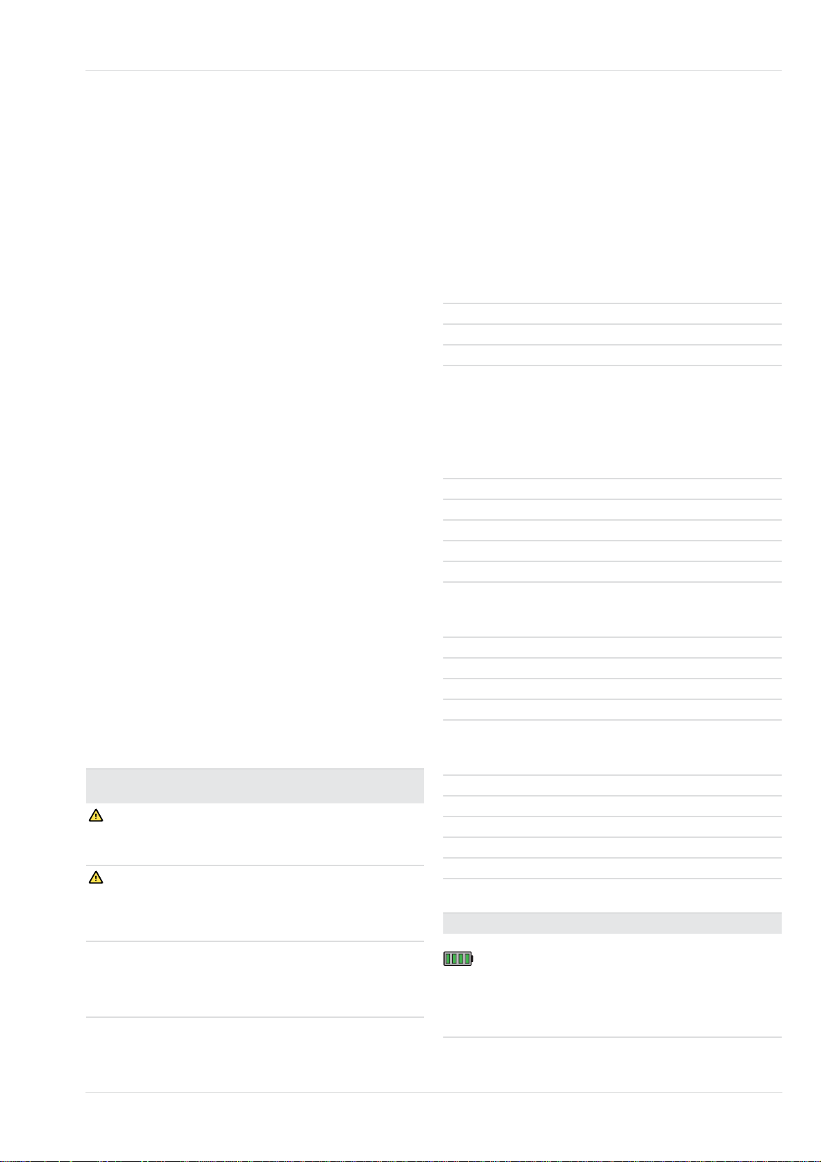
Display on control panel
Indicator Meaning
Battery capacity depending
on number of displayed seg-
Segments light up in green.
ments:
> 75 % (4 segments)
> 50 % (3 segments)
> 25 % (2 segments)
< 25 % (1 segment)
,QVWUXFWLRQVIRUXVH_'U¦JHU;SORUHp
Page 3
HQ_Description
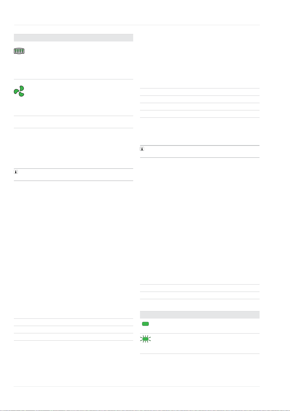
Indicator Meaning
Residual particle filter capac-
1)
depending on number of
ity
Segments light up in green.
Segments light up in green.
Segments blink yellow or red. Fault (see chapter
1) The residual capacity of the gas filter or the gas filter components of
the combination filter cannot be indicated.
Warning devi ce s
The fan unit displays malfunctions with segments flashing red
or yellow on the control panel. The fan unit will also trigger an
sound and vibration alarm.
Depending on the thickness and material of the clothing,
the vibration alarm might not be perceived.
displayed segments:
> 75 % (4 segments)
> 50 % (3 segments)
> 25 % (2 segments)
< 25 % (1 segment)
Flow rate intensity depending
on number of displayed segments:
high flow rate (3 segments)
medium flow rate (2 segments)
low flow rate (1 segment)
4 Troubleshooting)
2.2.2 Filter and facepieces
Filter and facepieces are described in separate Instructions
for Use.
The facepiece half/full mask types and hood/helmet/protective
visor have varying flow ranges. The fan unit automatically
detect the respiration connection type and automatically
selects the appropriate flow range.
2.2.3 Breathing hoses
The following breathing hoses are available:
– standard hose
– flexible hose for increased comfort
Both breathing hoses are available for each of the following
facepiece types:
– plug-in connector (hood)
– bayonet-type connector (helmet and protective visor)
– round-thread connector (half/full face mask)
2.2.4 Carrying systems
Illustration on the fold-out page (Figure E)
The decontaminable belt has a smooth plastic webbing
and is particularly recommended for decontamination.
– Welding belt
For the welding belt, the webbing is made of leather. The
welding belt is intended for use when welding.
2.2.5 Rechargeable batteries
Illustration on the fold-out page (Figure F)
1 Battery lock button
2 Battery status indicator
3 Button to display battery capacity
4 Docking Station
5 Name plate
The rechargeable lithium-ion batteries are specially designed
for use with the powered air purifying respirator. A long-life
rechargeable battery is also available in addition to the
standard rechargeable battery.
Rechargeable batteries for the different X-plore 8500 and
X-plore 8700 device types cannot be interchanged.
The battery status indicator shows the battery capacity while
you charge the unit with the standard charger or when you
push the button. The segments of the battery status indicator
are flashing while you charge the unit.
The battery status indicator is identical to the one on the fan
unit control panel (see chapter 2.2.1 Fan unit).
The rechargeable batteries reach their full capacity after
5 charge and discharge cycles. The standard charging time
takes approx. 3 hours.
In cases where the rechargeable battery has been completely
drained, charging may take up to 4 hours. During this time the
battery status indicator is not supported.
To prevent damage to or explosion of the rechargeable
battery, charging is limited to a temperature range of 0 to
50 °C. If this temperature range is transgressed, the charging
process will stop automatically and continue once the
temperature range is reached once again.
2.2.6 Standard battery charger
Illustration on the fold-out page (Figure G)
1Status LED
2 Power supply unit
3 Battery compartment
Explanation of the status LED
1 Connection plate
2 Webbing
3 Clips on ends of the belt
4 Buckle
The following carrying systems are available:
– Standard belt
The standard belt consists of a textile webbing and press
studs to attach comfortable padding.
– Decontaminable belt
,QVWUXFWLRQVIRUXVH_'U¦JHU;SORUHp
Indicator Meaning
Rechargeable battery is inserted and
Status LED is green.
Status LED is flashing green.
fully charged (standby mode)
Rechargeable battery is inserted and
being charged.
Page 4

Description_HQ
Indicator Meaning
Temporary disruption of charging
Status LED is flashing yellow.
Status LED is red.
Status LED is flashing red.
When the rechargeable battery is fully charged, the charger
switches automatically to standby. In standby mode, the
rechargeable battery stays fully charged at all times. In this
mode the rechargeable battery is neither overcharged nor
damaged.
(e.g. from excessively high temperature)
Rechargeable battery is not inserted.
Malfunction
(see chapter 4 Troubleshooting)
2.3 Feature description
The powered air purifying respirator is a respiratory protective
device depending on circulating air. It filters the ambient air
and makes it available as breathable air. The device
continuously takes in ambient air through the filter. The filter
absorbs harmful substances depending on the filter type. In
this way, the ambient air is recycled and finally reaches the
facepiece. There it is available as breathable air.
A continuous overpressure in the facepiece prevents ambient
air from penetrating.
2.4 Intended use
Depending on the employed filter type, the device protects
against particles, gases and vapours or combinations hereof.
Only powered air purifying respirator X-plore 8700 is intended
for use in explosion-hazard areas.
In explosion-hazard areas, the X-plore 8700 fan unit may
not be used with the welding protective visor (component list
pos. 19), the standard hood, long (pos. 10 and 11) and the
hose cover, disposable (pos. 41).
2.6 Approvals
2.6.1 Respiratory protection
The powered air purifying respirator is approved according to
– EN 12941
– EN 12942
– AS/NZS 1716:2012
The device satisfies the regulation on personal protective
equipment.
2.6.2 ATEX and IECEx
The X-plore 8700 powered air purifying respirator is approved
under designation APR 00** according to
– EN/IEC 60079-0
– EN/IEC 60079-11
The device satisfies the ATEX Directive 2014/34/EU.
Name of device according to ATEX
II 2G Ex ib IIB T4 Gb
II 2D Ex ib IIIB T135 °C Db
TA: -10 °C < Ta < +50 °C
Name of device according to IECEx
Ex ib IIB T4 Gb
Ex ib IIIB T135 °C Db
T
A: -10 °C < Ta < +50 °C
For an overview of the device combinations and the
protection classes, refer to the Configuration Matrix at the end
of these instructions for use.
The numbers in the first line of the Configuration Matrix
correspond to the positions in the component list.
The listed components are intended for use with the Xplore 8000 fan units (component list pos. 1 and 2) and the
rechargeable batteries (pos. 3 and 6).
Dräger would be happy to answer any questions you may
have regarding device configuration.
2.5 Limitations on use
The device is not suitable for use:
– when there is a suspicion of contaminants with low
warning properties (smell, taste, irritation of eyes and
airways)
– in unventilated tanks, pits, canals etc.
– when there is suspicion of contaminant concentrations
that represent an immediate danger to life or health - IDLH
concentrations
2.7 Explanation of type-identifying
marking and symbols
2.7.1 Name plates
Illustration of the name plates, refer to fold-out page.
Fan unit Figure H
Rechargeable battery
Standard battery
charger
1 Product name
2 International Protection Code
3 Approval marking
4 Symbol "Follow instructions for use"
5 WEEE symbol "Separate collection of electrical and
electronic equipment"
6 Country of production
7Manufacturer
8 CE marking
9 DataMatrix code with part and serial number
Figure I
Figure J
,QVWUXFWLRQVIRUXVH_'U¦JHU;SORUHp
Page 5

HQ_Use
≤95%
-20°C
+60°C
10 Serial number
11 Part number
12 Only for indoor use, not for outdoor use
13 Maximum ambient temperature
14 Electrical data
15 Pin assignment
16 Recycling symbol
17 Warning notice
Year of manufacture by serial number
1)
2.7.2 Packaging
Symbol Explanation
Follow the instructions for use
Maximum storage area humidity 95 %
Storage temperature range -20 °C to
+60 °C
3 Use
3.1 Preconditions for use
WARNING
Fire hazard due to sparks or liquid metal splashes
Ź Always use powered air purifying respirators with a
particle or combination filter with additional prefilter if
sparks or liquid metal splashes may occur during use.
Ź Replace the prefilter at regular intervals; at least once per
shift, but in case of visible contamination at the very latest.
Ź Replace particle and combination filters as soon as they
are visibly contaminated with dust even if the residual
capacity indicator of the powered air purifying respirator
indicates that the residual capacity is still sufficient.
Ź Avoid direct contact of sparks and liquid metal splashes
with the powered air purifying respirator: Contact of a
heavily contaminated prefilter, particle or combination filter
with sparks or liquid metal splashes can cause damage to
the filter or ignite the collected particles.
– The ambient conditions (in particular type and
concentration of the contaminants) must be known.
– The oxygen content of the ambient air must not drop
below the following limit values:
– at least 17 Vol% oxygen in all European countries
except for the Netherlands, Belgium and Great Britain
– At least 19 Vol% oxygen in the Netherlands, Belgium,
the UK, Australia and New Zealand.
– At least 19.5 Vol% oxygen in the USA
Observe the national guidelines in other countries.
1) The year of manufacture results from the 3rd letter of the serial number: F = 2014, G = omitted, H = 2015, I = omitted, J = 2016, K = 2017
etc. Example: Serial number ARFH-0054: The third letter is F, the year
of manufacture is therefore 2014.
3.2 Preparation for use
WARNING
Ambient air penetration
Incorrect assembly of the components can impair the device
function.
Ź For rechargeable battery, splash guard cover, and gas
filter or combination filter ensure that:
– Both connection points engage into the intended
sockets when inserted
– Do not jam the respective components when they are
snapped into place
Perform the following activities outside the danger zone:
1. Select components of the powered air purifying respirator
according to the required protection class and task (see
Configuration Matrix at the end of these instructions for
use).
2. Carry out a visual inspection (see chapter 5.3.1 Visual
inspection).
3. Checking the rechargeable battery capacity:
a. Press the button to display the battery capacity on the
rechargeable battery.
b. Read the battery status indicator.
c. If the battery capacity is insufficient for the planned
period of service: Replace or charge the rechargeable
battery (see chapter 5.3.2 Replacing or charging the
rechargeable battery)
It might be required to fully charge the rechargeable
battery prior to the first commissioning of the device.
4. Insert filter (see chapter 5.3.3 Replacing the filter).
5. Assembling the carrying system:
36379
a. Position both connection points of the connection plate
on the fan unit sockets. Ensure that the arrows on the
belt and the rear of the fan unit go together.
b. Push down connection plate until it snaps audibly into
place.
6. Attach accessories if applicable:
Ź Attach comfortable padding to the standard belt with
the press studs.
Ź If needed, the belt extension is attached to the belt
buckle.
For any other accessories refer to the enclosed
assembly instructions.
7. Donning the device:
,QVWUXFWLRQVIRUXVH_'U¦JHU;SORUHp
Page 6

Troubleshooting_HQ
a. Adjust the carrying system belt to approximately the
correct circumference.
b. Put on belt and close buckle. The device is located on
the back of the user.
c. Tighten belt and fasten protruding ends with clips on
ends of the belt.
8. Connecting the facepiece:
a. Connect the plug-in connector of the breathing hose to
the fan unit.
b. Connect the other end of the breathing hose to the
facepiece.
9. Switch on the fan unit by pushing the button on the
control panel for approx. 2 seconds.
The device performs a self-test. If the device does not
work properly or warning devices are triggered,
eliminate the fault (see chapter 4 Troubleshooting).
10. Don the facepiece (see Instructions for Use of the
corresponding facepiece).
11. Adjust he volume flow as desired using the and
buttons.
3.3 During use
WARNING
Health hazard
Ź Leave the danger zone immediately in case of:
– Decreasing or interrupted air supply (e.g. after fan
failure). In the hood/helmet/protective visor facepiece
type, carbon dioxide can quickly build up or lack of
oxygen may occur. Noxious ambient air may also
penetrate the hood.
– Odour or taste developing in the facepiece (filter
break). The residual capacity of the gas filter or the gas
filter components of the combination filter are
exhausted.
– Drowsiness, dizziness, or other complaints
– Damage to the equipment
– Displayed alarms
Breathing hoses or other components involve the risk of
getting caught. This may damage the device and interrupt
the air supply!
Handle the device with care.
Breathing in during heavy work while wearing the
hood/helmet/protective visor facepiece type may result in
negative pressure and the penetration of unfiltered
ambient air!
Increase the flow rate to prevent this from happening.
3.3.1 Adjusting the flow rate
If necessary (e.g. during increased physical exertion), the flow
rate must be adjusted during operation using the and
buttons.
3.3.2 Warnings and alarms
If a warning appears, leave the working area promptly in view
of the potentially hazardous situation.
Lower the flow rate to increase the period of service if a
warning appears. (Only possible if the lowest level has not
already been chosen.) By lowering the flow rate, you can, for
example, extend the battery runtime.
If an alarm is triggered, leave the working area immediately
without any delay.
Check the function of the device after a warning or alarm has
been triggered.
3.4 After use
Do the following:
1. Leave the hazardous area.
2. Remove the facepiece (see Instructions for Use of the
corresponding facepiece).
3. Switch off the fan unit by pushing the button on the
control panel for approx. 2 seconds.
4. Open the carrying system belt and take off the device.
5. Clean and disinfect the device (see chapter 5.2 Cleaning
and disinfecting).
4 Troubleshooting
4.1 Warnings
Fault Cause Remedy
The residual run-
A segment of the
battery status indicator is flashing
yellow.
A segment of the
particle filter residual capacity indicator is flashing
yellow.
A segment of the
flow rate indicator
is flashing yellow.
time of the
rechargeable battery is low
(< 30 minutes).
The particle filter
residual capacity is
low (< 20 %).
Malfunction during
switch-on (e.g.
caused by missing
hose or filter).
4.2 Alarms
4.2.1 Fan unit
Fault Cause Remedy
The residual run-
A segment of the
battery status indicator is flashing
red.
A segment of the
particle filter residual capacity indicator is flashing red.
A segment of the
flow rate indicator
is flashing red.
time of the
rechargeable battery is almost
exhausted
(< 10 minutes)
The particle filter
residual capacity is
almost exhausted
(< 10 %)
Faulty breathing air
supply during operation (e.g. caused
by missing hose,
filter or kinked
hose).
Recharge the battery soon or
replace with fully
charged battery.
Change particle or
combination filter
soon.
Re-check the
device function
and prepare for
use.
Recharge the battery or replace with
fully charged battery.
Change particle or
combination filter.
Re-check the
device function
and prepare for
use.
,QVWUXFWLRQVIRUXVH_'U¦JHU;SORUHp
Page 7

HQ_Maintenance
Fault Cause Remedy
One segment at a
time is flashing red.
General system
error
Device must be
checked by Dräger
Service.
4.2.2 Standard battery charger
Fault Cause Remedy
Status LED is
flashing red.
General error or
defect
Re-insert the
rechargeable battery in the battery
charger. If the error
occurs repeatedly
have Dräger Service check the battery charger and
rechargeable battery.
5 Maintenance
5.1 Maintenance intervals
Work to do
d. Dismantle the splash guard cover and filter (see
chapter 5.3.3 on page 12).
2. Clean the facepiece according to the appropriate
Instructions for Use.
3. Cleaning the breathing hose and carrying system:
a. Clean all parts with luke-warm water using Sekusept
Cleaner
concentration depending on contamination: 0.5 - 1 %).
b. Rinse all parts thoroughly under running water.
c. Prepare a disinfectant bath of water and Incidin
Rapid
1.5 %)
d. Place all parts to be disinfected into the disinfectant
bath (duration: 15 minutes).
e. Rinse all parts thoroughly under running water.
f. Allow all parts to air-dry or dry them in the drying
cabinet (temperature: max. 60 °C). Keep away from
direct sunlight.
4. Clean and disinfect fan unit and splash guard cover using
Incides
In cases of strong contamination, the fan unit can be rinsed
under running water as follows.
1. Make sure the rechargeable battery remains inserted.
Water must not enter the battery compartment.
2. Close suction inlet and tube connection with plug
(available as accessories).
1)
and a soft cloth (temperature: max. 30 °C,
2)
(temperature: max. 30 °C, concentration:
®
N disinfectant cloths*.
®
®
Annually
Clean and disinfect the device
Visual inspection
Replacing the O-ring at plug-in or bayonet-type hose connector
1) for gas-tight packed devices, otherwise every 6 months
X
Every 2 years
1)
X
1)
X
5.2 Cleaning and disinfecting
CAUTION
Health hazard
The undiluted agents are damaging to health if they come into
direct contact with the eyes or skin.
Ź Wear safety goggles and protective gloves when working
with these agents.
NOTICE
Potential damage to components
Ź Only use the prescribed processes and the cleaning and
disinfection agents specified for cleaning and disinfecting.
Other agents, methods, dosages and contact times may
damage the components.
5.2.1 Clean and disinfect the device
1. Dismantling the device:
a. Separate breathing hose, facepiece and fan unit from
each other.
b. Disconnect the carrying system from the fan unit.
c. If available, dismantle any accessories (e.g. hose and
device sleeves).
5.3 Maintenance work
5.3.1 Visual inspection
Check all parts thoroughly and replace damaged parts if
necessary. In particular, check the filter sealing surface and
O-rings of the fan unit for damage (e.g. scratches) or
contamination.
5.3.2 Replacing or charging the rechargeable
battery
WARNING
Explosion, fire or chemical hazard!
Ź Do not remove, insert or charge rechargeable batteries in
potentially explosive or flammable environments.
Ź Keep rechargeable batteries away from sources of heat.
Ź Do not short-circuit the rechargeable battery contacts.
Ź Only use recommended rechargeable batteries.
Removing the rechargeable battery:
1. Fold up carrying system if necessary.
2. Push battery lock button. Ensure that the rechargeable
battery does not fall down.
3. Remove rechargeable battery.
Inserting the rechargeable battery:
1. Fold up carrying system if necessary.
2. Position the two lower connection points of the
rechargeable battery at an angle in the battery
compartment sockets.
1) Sekusept® and Incides® are registered trademarks of Ecolab
Deutschland GmbH.
2) Incidin® is a registered trademark of Ecolab USA Inc.
,QVWUXFWLRQVIRUXVH_'U¦JHU;SORUHp
Page 8

Transport_HQ
A
A
B
3. Fold the rechargeable battery in until it snaps audibly into
place.
Always disconnect the charger from the power supply if not
in use.
The standard rechargeable battery (EX) and the long-life
rechargeable battery (EX) may only be charged using the
Dräger X-plore 8000 standard charger (order no. R59780).
Charging the battery:
1. Check to make sure that voltage of mains supply is
correct. The operational voltage of the power supply unit
must match the mains supply voltage.
2. Connect charger to power supply unit.
3. Connect the power supply unit to the mains supply.
4. First position the rechargeable battery at an angle in the
charger and then fold it in until it snaps audibly into place.
5. Wait for the end of the charging process.
6. When the rechargeable battery is fully charged, push the
battery lock button and remove the battery.
7. Disconnect the power supply unit and charger from the
mains supply.
5.3.3 Replacing the filter
WARNING
No protection without filter!
Ź Do not use the device without filter.
CAUTION
Damage to fan unit due to penetration of particles!
Ź Make sure when you remove the filter that no particles
enter the device through the suction inlet.
The filter changing process may differ depending on the
filter type used.
Particle filter
B
Removing the filter:
1. Push filter lock button.
2. Fold out splash guard cover with filter (Figure A).
Remove used filter (Figure B). Inserting the filter:
1. Check rubber seal on filter for damage.
2. Insert new filter into splash guard cover so that the filter is
firmly seated in the splash guard cover.
3. Hook the two lower connection points of the splash guard
cover at an angle into the fan unit sockets.
4. Fold splash guard cover in until it audibly snaps into place
at the filter lock button.
Gas or combination filter
Removing the filter:
1. Push filter lock button.
2. Fold filter with splash guard cover out (Figure A).
3. Dismantling the splash guard cover:
a. Press on the centre of the upper splash guard cover
edge until it snaps out.
b. Fold out splash guard cover (Figure B).
Inserting the filter:
1. Check rubber seal on filter for damage.
2. Place splash guard cover with its lower edge at an angle
on the filter.
3. Push on splash guard cover until it snaps audibly into
place.
4. Hook the two lower connection points of the filter at an
angle into the fan unit sockets.
5. Fold filter in until it audibly snaps into place at the filter lock
button.
5.3.4 Checking the flow rate and warning
devices
1. Make sure that a filter is inserted.
2. Connect the plug-in connector of the breathing hose to the
fan unit.
3. Switch on the fan unit by pushing the button on the
control panel.
After it is switched on, the device performs a self-test.
If the device does not work properly or warning
devices are triggered, eliminate the fault.
4. Cover the open end of the breathing hose with the palm of
your hand.
The fan unit starts operating more intensively after
about 5 seconds. An alarm is triggered after about
20 seconds.
Have the fan unit checked if the fan speed remains
unchanged and no alarm is triggered.
5. If you wish, you can switch off the fan unit by pushing the
button on the control panel once again.
5.3.5 Replacing the O-ring at plug-in or bayonet-
type hose connector
1. Use the O-ring removal tool to lift the old O-ring out of the
groove.
2. Insert new O-ring in the provided groove.
6 Transport
Transport in the original packaging or in optionally available
transport box.
,QVWUXFWLRQVIRUXVH_'U¦JHU;SORUHp
Page 9

HQ_Storage
7 Storage
Storing the whole system:
– Remove filter and rechargeable battery.
– Dry the components in a container or cabinet. Store them
dry and clean and protect them from direct sunlight and
thermal radiation.
Storing rechargeable batteries:
– Deeply discharged batteries may get damaged after
prolonged storage. Charge the rechargeable batteries to
50 to 70 % prior to storage.
– If storage lasts for over 6 months, charge the
rechargeable batteries intermittently.
– Do not store rechargeable batteries for prolonged periods
outside the recommended temperature range. This might
reduce the remaining capacity and number of potential
charge cycles.
8 Disposal
This product must not be disposed of as municipal
waste. It is therefore marked with the adjacent symbol.
This product can be returned to Dräger free of charge.
Please contact your national Dräger Sales Organisation or Dräger for more information.
Batteries and rechargeable batteries must not be disposed of as municipal waste. They are therefore
marked with the symbol on the left. Collect batteries
and rechargeable batteries according to local regulations and dispose of at battery collection centres.
9 Technical data
9.1 Overall system
Flow rate of respiratory protective device/helmet/visor:
Flow rate of half/full face
mask:
Rated period of service: 4 hours with standard
Operating temperature
1)2)
Working and storage area
humidity
Storage temperature
1)
1)
Noise: approx. 64 dB(A)
International Protection Code IP 65
1) Battery charger and rechargeable batteries, see separate information
in this chapter. Other components, see corresponding instructions for
use.
2) For X-plore 8700 in explosion-hazard areas -10 °C to +50 °C.
RFID
Technology Induction transfer
Frequency range 13553 to 13567 kHz
170/190/210 L/min
115/130/145 L/min
rechargeable battery
8 hours with long-life
rechargeable battery
-10°C to +60°C
95 % relative humidity
-20°C to +60°C
Broadcast transmission
-2.30 dBμA/m (10 m)
capacity
Bluetooth
Technology FHSS 2.4 GHz (BT 2.1 +
EDR)
Frequency range 2402.0 to 2483.5 MHz
Broadcast transmission
0.97 mW / -0.14 dBm EIRP
capacity
9.2 Rechargeable batteries
Operating temperature
1)
Operating/storage area
humidity:
Storage temperature -20 °C to +50 °C
Charging temperature: 0 °C to +50 °C
1) For rechargeable batteries for X-plore 8700 in explosion-hazard areas
-10 °C to +50 °C.
Standard rechargeable battery
Charging time: < 4 hours
Operational life time after a
full charge
Rated voltage 10.8 V
Rated capacity: 3.35 Ah
Stored energy 36 Wh
1) Varies depending on the preset flow rate and the employed filter and
facepiece type
Long-life rechargeable battery
Charging time: < 4 hours
Operational life time after a
full charge
Rated voltage 10.8 V
Rated capacity: 6.70 Ah
Stored energy 72 Wh
1) Varies depending on the preset flow rate and the employed filter and
facepiece type
-10 °C to +60 °C
95 % relative humidity
approx. 4 hours
approx. 8 hours
1)
1)
9.3 Standard battery charger
Input voltage 16 V
Input current: 3,75 A
Output voltage: 9 - 12.6 V
Output current: 4 A
International Protection Code IP 30
Operating temperature 0 °C to 50 °C
Operating/storage area
humidity:
Storage temperature -20 °C to 50 °C
95 % relative humidity
,QVWUXFWLRQVIRUXVH_'U¦JHU;SORUHp
Page 10

Component list_HQ
10 Component list
The positions in the component list correspond to the figures
in the top row of the configuration matrix at the end of these
instructions for use.
Components
Position
1 Dräger X-plore 8500 fan unit R59500
2 Dräger X-plore 8700 (EX) fan unit R59550
3 Dräger X-plore 8000 standard
4 Dräger X-plore 8000 standard
5 Dräger X-plore 8000 long-life recharge-
6 Dräger X-plore 8000 long-life recharge-
7 Dräger X-plore 8000 standard charger R59780
8 Dräger X-plore 8000 standard hood,
9 Dräger X-plore 8000 standard hood,
10 Dräger X-plore 8000 standard hood,
11 Dräger X-plore 8000 standard hood,
12 Dräger X-plore 8000 premium hood,
13 Dräger X-plore 8000 premium hood,
14 Dräger X-plore 8000 premium hood,
15 Dräger X-plore 8000 premium hood,
16 Dräger X-plore 8000 helmet with visor,
17 Dräger X-plore 8000 helmet with visor,
18 Dräger X-plore 8000 protective visor R59900
19 Dräger X-plore 8000 welding protective
20 Dräger X-plore 6300 EPDM/PMMA R55800
21 Dräger X-plore 6530 EPDM/PC R55795
22 Dräger X-plore 6570 SI/PC R55790
23 Dräger X-plore 4740 SI S/M R55875
24 Dräger X-plore 4740 SI M/L R55874
25 Dräger FPS 7000 EPDM-S1-PC-CR R56502
26 Dräger FPS 7000 EPDM-M2-PC-CR R56310
27 Dräger FPS 7000 EPDM-L2-PC-CR R56503
28 Dräger X-plore 8000 standard hose (for
Name Order
no.
R59565
rechargeable battery
R59575
rechargeable battery (EX)
R59585
able battery
R59595
able battery (EX)
R59800
short (S/M)
R59810
short (L/XL)
R59820
long (S/M)
R59830
long (L/XL)
R59840
short (S/M)
R59850
short (L/XL)
R59860
long (S/M)
R59870
long (L/XL)
R58325
black
R59910
white
R59940
visor with ADF 5 - 13
R59630
half/full face masks)
Position
29 Dräger X-plore 8000 standard hose (for
Name Order
no.
R59620
hoods)
30 Dräger X-plore 8000 standard hose (for
R59640
helmets and visors)
31 Dräger X-plore 8000 flexible hose (for
R59610
half/full face masks)
32 Dräger X-plore 8000 flexible hose (for
R59600
hoods)
33 Dräger X-plore 8000 flexible hose (for
R59650
helmets and protective visors)
34 Dräger X-plore 8000 standard belt R59700
35 Dräger X-plore 8000 belt, decontam-
R59710
inable
36 Dräger X-plore 8000 Welding belt R59720
Accessories
Position
37 Dräger X-plore 8000 comfortable pad-
Name Order
no.
R59730
ding
38 Belt extension for X-plore 8000 stan-
R59750
dard belt, 35 cm
39 Belt extension for X-plore 8000 belt,
R59760
decontaminable, 35 cm
40 Dräger X-plore 8000 Neck strap sys-
R59740
tem, all belts
41 Dräger X-plore 8000 Hose cover, dis-
R59670
posable
42 Dräger X-plore 8000 Hose cover, spark
R59660
protection
43
Dräger X-plore Tyvek
1)
hood
®
protective
R55354
44 Dräger X-plore 8000 Prefilter 6739730
45 Dräger X-plore 8000 Odour filter 6739605
1) Tyvek® is a registered trademark of E.I. Du Pont de Nemours and Co.
,QVWUXFWLRQVIRUXVH_'U¦JHU;SORUHp
 Loading...