


XPLORE8500
Dräger X-plore
®
8000
de
Gebrauchsanweisung
5
pl
Instrukcja obsáugi
121
en
Instructions for Use
15
ru
Ɋɭɤɨɜɨɞɫɬɜɨ ɩɨ ɡɤɫɩɥɭɚɬɚɰɢɢ
132
fr
Notice d’utilisation
25
hr
Upute za uporabu
144
es
Instrucciones de uso
36
sl
Navodilo za uporabo
155
pt
Instruções de utilização
47
sk
Návod na použitie
166
it
Istruzioni per l'uso
58
cs
Návod na použití
177
nl
Gebruiksaanwijzing
69
bg
Ɋɴɤɨɜɨɞɫɬɜɨ ɡɚ ɪɚɛɨɬ
188
da
Brugsanvisning
80
ro
InstrucĠiuni de utilizare
200
fi
Käyttöohjeet
90
hu
Használati útmutató
211
no
Bruksanvisning
100
tr
Kullanma talimatlarÕ
222
sv
Bruksanvisning
110
zh
∎䞷広㢝
233

A
1
4
2
3
B
5
6
3
21
4
C
0158
IP 65
EN 12941
EN 12942
CAXXX (Brasilien)
Contains FCC ID: T7VPAN10
Contains IC: 216Q-PAN10
Dräger Safety AG & Co. KGaA, 23560 Lübeck, Germany Made in Germany
X-plore 8500 (IP)
Part-No. : R59XXX
Serial-No. : AREE-0001
2
5
1
43
4
1
2 3
F
334
2
1
E
D
1
2
6
5
34
00133412.eps
3
2
1
G
4 Dräger X-plore 8000
00233412.eps
J
X-plore 8000 Standard Charger
IP 30
T50
Input: 15 V / 4 A
Output: 9 - 12,6 V / 4 A
Dräger Safety AG & Co. KGaA, 23560 Lübeck, Germany Made in China
X
Part-No. : R59580
Serial-No. : AREE-0001
1 92
4
12
7
67 15 13
9
10
11
14
X
0158
IP 65
EN 12941
EN 12942
Dräger Safety AG & Co. KGaA, 23560 Lübeck, Germany Made in Germany
X-plore 8000
Standard Battery
Part-No. : R59565
Serial-No. : AREE-0001
Rechargeable Li-Ion Battery 10,8 V; 3,35 Ah; 36 Wh
Must be recycled or disposed of properly
Caution: Charge with dedicated charger only
May explode if damaged or disposed of in fire
Do not short circuit
1 17
9
10
11
8
23
6
4
5
16
7
I
H
X
0158
IP 65
EN 12941
EN 12942
Dräger Safety AG & Co. KGaA, 23560 Lübeck, Germany Made in Germany
X-plore 8500 (IP)
Part-No. : R59500
Serial-No. : AREE-0001
123
4
5
67
8
9
10
11

Inhalt
Dräger X-plore® 8000 5
Inhalt
1 Zu Ihrer Sicherheit . . . . . . . . . . . . . . . . . . . . . . . . .6
1.1 Allgemeine Sicherheitshinweise . . . . . . . . . . . . . . . .6
1.2 Bedeutung der Warnzeichen . . . . . . . . . . . . . . . . . .6
2 Beschreibung . . . . . . . . . . . . . . . . . . . . . . . . . . . . .6
2.1 Systemübersicht . . . . . . . . . . . . . . . . . . . . . . . . . . . .6
2.2 Komponenten . . . . . . . . . . . . . . . . . . . . . . . . . . . . . .6
2.2.1 Gebläseeinheit . . . . . . . . . . . . . . . . . . . . . . . . . . . . .6
2.2.2 Filter und Atemanschlüsse . . . . . . . . . . . . . . . . . . . .7
2.2.3 Atemschläuche . . . . . . . . . . . . . . . . . . . . . . . . . . . . .7
2.2.4 Tragesysteme . . . . . . . . . . . . . . . . . . . . . . . . . . . . . .7
2.2.5 Akkus . . . . . . . . . . . . . . . . . . . . . . . . . . . . . . . . . . . .7
2.2.6 Ladegeräte . . . . . . . . . . . . . . . . . . . . . . . . . . . . . . . .7
2.3 Funktionsbeschreibung . . . . . . . . . . . . . . . . . . . . . . .8
2.3.1 Warneinrichtungen . . . . . . . . . . . . . . . . . . . . . . . . . .8
2.4 Verwendungszweck . . . . . . . . . . . . . . . . . . . . . . . . .8
2.5 Einschränkungen des Verwendungszwecks . . . . . . .8
2.6 Zulassungen . . . . . . . . . . . . . . . . . . . . . . . . . . . . . . .8
2.7 Symbolerklärung und typidentische Kennzeichnung 8
2.7.1 Typenschilder . . . . . . . . . . . . . . . . . . . . . . . . . . . . . .8
2.7.2 Verpackung . . . . . . . . . . . . . . . . . . . . . . . . . . . . . . . .9
3 Gebrauch . . . . . . . . . . . . . . . . . . . . . . . . . . . . . . . . .9
3.1 Voraussetzungen für den Gebrauch . . . . . . . . . . . . .9
3.2 Vorbereitungen für den Gebrauch . . . . . . . . . . . . . .9
3.2.1 Tragesystem montieren . . . . . . . . . . . . . . . . . . . . . .9
3.2.2 Gerät anlegen . . . . . . . . . . . . . . . . . . . . . . . . . . . . . .9
3.2.3 Atemanschluss anschließen . . . . . . . . . . . . . . . . . . .9
3.2.4 Gerät einschalten . . . . . . . . . . . . . . . . . . . . . . . . . . .9
3.3 Während des Gebrauchs . . . . . . . . . . . . . . . . . . . .10
3.3.1 Volumenstrom nachregulieren . . . . . . . . . . . . . . . .10
3.3.2 Warnungen und Alarme . . . . . . . . . . . . . . . . . . . . .10
3.4 Nach dem Gebrauch . . . . . . . . . . . . . . . . . . . . . . . .10
3.5 Allgemeine Benutzeraufgaben . . . . . . . . . . . . . . . .10
3.5.1 Komfortpolster für Standardgürtel anbringen . . . . .10
3.5.2 Gurtverlängerung am Tragesystem anbringen . . . .10
4 Störungsbeseitigung . . . . . . . . . . . . . . . . . . . . . .10
4.1 Warnungen . . . . . . . . . . . . . . . . . . . . . . . . . . . . . . .10
4.2 Alarme . . . . . . . . . . . . . . . . . . . . . . . . . . . . . . . . . . .11
5 Wartung . . . . . . . . . . . . . . . . . . . . . . . . . . . . . . . . .11
5.1 Instandhaltungsintervalle . . . . . . . . . . . . . . . . . . . .11
5.2 Reinigung und Desinfektion . . . . . . . . . . . . . . . . . .11
5.2.1 Gerät reinigen und desinfizieren . . . . . . . . . . . . . . .11
5.3 Wartungsarbeiten . . . . . . . . . . . . . . . . . . . . . . . . . .11
5.3.1 Sichtprüfung durchführen . . . . . . . . . . . . . . . . . . . .11
5.3.2 Ladezustand des Akkus prüfen . . . . . . . . . . . . . . . .12
5.3.3 Akku wechseln oder laden . . . . . . . . . . . . . . . . . . .12
5.3.4 Filter wechseln . . . . . . . . . . . . . . . . . . . . . . . . . . . .12
5.3.5 Volumenstrom und Warneinrichtungen prüfen . . . .12
5.3.6 O-Ring am Steck- oder Bajonettanschluss der
Schläuche wechseln . . . . . . . . . . . . . . . . . . . . . . . .13
6 Transport . . . . . . . . . . . . . . . . . . . . . . . . . . . . . . . .13
7 Lagerung . . . . . . . . . . . . . . . . . . . . . . . . . . . . . . . .13
8 Entsorgung . . . . . . . . . . . . . . . . . . . . . . . . . . . . . 13
9 Technische Daten . . . . . . . . . . . . . . . . . . . . . . . . 13
10 Bestellliste . . . . . . . . . . . . . . . . . . . . . . . . . . . . . . 14

6 Dräger X-plore 8000
Zu Ihrer Sicherheit
1 Zu Ihrer Sicherheit
1.1 Allgemeine Sicherheitshinweise
z Vor Gebrauch des Produkts diese Gebrauchsanweisung
und die der zugehörigen Komponenten aufmerksam lesen.
z Gebrauchsanweisung genau beachten. Der Anwender
muss die Anweisungen vollständig verstehen und den
Anweisungen genau Folge leisten. Das Produkt darf nur
entsprechend dem Verwendungszweck verwendet
werden.
z Gebrauchsanweisung nicht entsorgen. Aufbewahrung und
ordnungsgemäße Verwendung durch die Nutzer
sicherstellen.
z Nur geschultes und fachkundiges Personal darf dieses
Produkt verwenden.
z Lokale und nationale Richtlinien, die dieses Produkt
betreffen, befolgen.
z Nur geschultes und fachkundiges Personal darf das
Produkt überprüfen, reparieren und instand halten.
z Nur Original-Dräger-Teile und -Zubehör verwenden. Sonst
könnte die korrekte Funktion des Produkts beeinträchtigt
werden.
z Fehlerhafte oder unvollständige Produkte nicht
verwenden. Keine Änderungen am Produkt vornehmen.
z Dräger bei Fehlern oder Ausfällen vom Produkt oder von
Produktteilen informieren.
1.2 Bedeutung der Warnzeichen
Die folgenden Warnzeichen werden in diesem Dokument ver-
wendet, um die zugehörigen Warntexte zu kennzeichnen und
hervorzuheben, die eine erhöhte Aufmerksamkeit seitens des
Anwenders erfordern. Die Bedeutungen der Warnzeichen sind
wie folgt definiert:
2 Beschreibung
2.1 Systemübersicht
Das Gebläsefiltergerät Dräger X-plore
®
8000
1)
kann je nach
Einsatzbereich und erforderlicher Schutzklasse aus unter-
schiedlichen Komponenten zusammengesetzt werden. Hier-
bei insbesondere die Einsatzgrenzen der Filter beachten
(siehe Gebrauchsanweisung der Filter).
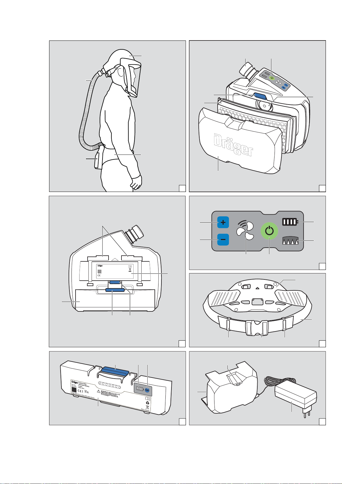
Ź Darstellung der Systemübersicht auf der Ausklappseite
(Abbildung A)
Zu einem vollständigen Gerät gehören:
1 Atemschlauch
2 Atemanschluss (Beispiel mit Helm)
3 Tragesystem
4 Gebläseeinheit mit Filter und Akku
Ggf. Zubehörkomponenten (ohne Abbildung)
2.2 Komponenten
2.2.1 Gebläseeinheit
Die Gebläseeinheit ist die zentrale Komponente des Geräts.
Gerätemerkmale:
z Bedienfeld mit Anzeige des aktuellen Systemzustands
z Elektronische Überwachung der Gerätefunktionen
{ Volumenstrom
{ Restkapazität des Partikelfilters
{ Ladezustand des Akkus
{ Erkennung vom Gerät getrennter Schläuche oder Filter
z Automatische Erkennung des verwendeten Ateman-
schlusstyps (Halb-/Vollmaske oder Haube/Helm/Schutzvi-
sier) und entsprechende Anpassung des
Volumenstrombereichs
z Dreistufig wählbarer Volumenstrom
z Optische Erkennung des Filtertyps über Farbkennzeich-
nung (Farbpunkt am Filter)
Ź Darstellung der Vorderseite der Gebläseeinheit auf der
Ausklappseite (Abbildung B)
1 Schlauchanschluss
2 Bedienfeld
3 Ansaugöffnung
4 Spritzschutzdeckel
5 Filter (nicht im Lieferumfang der Gebläseeinheit)
6 Filterverriegelungstaste
WARNUNG
Hinweis auf eine potenzielle Gefahrensituation.
Wenn diese nicht vermieden wird, können Tod oder
schwere Verletzungen eintreten.
VORSICHT
Hinweis auf eine potenzielle Gefahrensituation. Wenn
diese nicht vermieden wird, können Verletzungen oder
Schädigungen am Produkt oder der Umwelt eintreten.
Kann auch als Warnung vor unsachgemäßem Ge-
brauch verwendet werden.
HINWEIS
Zusätzliche Information zum Einsatz des Produkts.
1) X-plore
®
ist eine eingetragene Marke von Dräger.
!
!
i
i
HINWEIS
Für eine Übersicht der Gerätekombinationen und der
entsprechenden Schutzklasse siehe Konfigurations-
matrix (Configuration Matrix) auf Seite 243.
Die Zahlen in der oberen Zeile der Konfigurationsmat-
rix entsprechen den Positionen in der Bestellliste.
Die gelisteten Komponenten sind hierbei für die Ver-
wendung mit der X-plore 8500 Gebläseeinheit (Be-
stellliste Pos. 1) und den Akkus (Pos. 2 und 3)
bestimmt.
Bei Fragen zur Konfiguration des Geräts Dräger kon-
taktieren.
i
i

Beschreibung
Dräger X-plore 8000 7
Ź Darstellung der Rückseite der Gebläseeinheit auf der Aus-
klappseite (Abbildung C)
1 Tragesystemaufnahme
2 Typenschild
3 Tragesystem-Verriegelungstaste
4 Akkuverriegelungstaste
5 Akku (nicht im Lieferumfang der Gebläseeinheit)
Bedienfeld
Ź Darstellung auf der Ausklappseite (Abbildung D)
1 Ladezustandsanzeige des Akkus
2 Restkapazitätsanzeige des Partikelfilters
3 Ein/Aus-Taste
4 Volumenstromanzeige
5 Volumenstrom senken
6 Volumenstrom erhöhen
Bedeutung der Anzeigen auf dem Bedienfeld
2.2.2 Filter und Atemanschlüsse
Filter und Atemanschlüsse sind in separaten Gebrauchsan-
weisungen beschrieben.
2.2.3 Atemschläuche
Folgende Atemschläuche stehen zur Verfügung:
z Standardschlauch
z Flexibler Schlauch für erhöhten Komfort
Beide Atemschläuche sind jeweils für folgende Ateman-
schlusstypen erhältlich:
z Steckanschluss (Haube)
z Bajonettanschluss (Helm und Schutzvisier)
z Rundgewindeanschluss (Halb-/Vollmaske)
2.2.4 Tragesysteme
Ź Darstellung auf der Ausklappseite (Abbildung E)
1 Verbindungsplatte
2 Gurtband
3 Gurtendenklammern
4 Schnalle
Folgende Tragesysteme sind verfügbar:
z Standardgürtel
Der Standardgürtel verfügt über ein textiles Gurtband und
Druckknöpfe zum Befestigen eines optionalen Komfort-
polsters.
z Dekontaminierbarer Gürtel:
Der dekontaminierbare Gürtel verfügt über ein glattes
Kunststoff-Gurtband und ist speziell zum Dekontaminieren
geeignet.
2.2.5 Akkus
Ź Darstellung auf der Ausklappseite (Abbildung F)
1 Akkuverriegelungstaste
2 Ladezustandsanzeige
3 Taste zum Anzeigen des Ladezustands
4 Typenschild
Die Li-Ionen-Akkus sind speziell für den Einsatz mit dem Ge-
bläsefiltergerät ausgerüstet. Neben dem Standardakku ist
noch ein Langzeitakku mit höherer Betriebsdauer erhältlich.
Die Ladezustandsanzeige zeigt den Ladezustand während
des Ladens mit dem Standardladegerät oder beim Betätigen
der Taste. Während des Ladens blinken die Segmente der La-
dezustandsanzeige.
Die Ladezustandsanzeige entspricht der auf dem Bedienfeld
der Gebläseeinheit (siehe Kapitel 2.2.1 auf Seite 6).
Die Akkus erreichen erst nach 5 Lade- und Entladezyklen ihre
volle Kapazität. Die normale Ladezeit beträgt ca. 3 Stunden.
Bei starker Entladung wird der Akku vorgeladen, wodurch sich
die Ladezeit um bis zu 4 Stunden verlängern kann. In dieser
Zeit wird die Ladezustandsanzeige nicht unterstützt.
Um Beschädigung oder Explosion des Akkus auszuschließen,
erfolgt der Ladevorgang nur im Temperaturbereich von 0 bis
50 °C. Beim Verlassen des Temperaturbereichs wird der Lade-
vorgang automatisch unterbrochen und nach Rückkehr in den
Temperaturbereich fortgesetzt.
2.2.6 Ladegeräte
Standardladegerät
Ź Darstellung auf der Ausklappseite (Abbildung G)
1 Status-LED
2 Netzteil
3 Akkuaufnahme
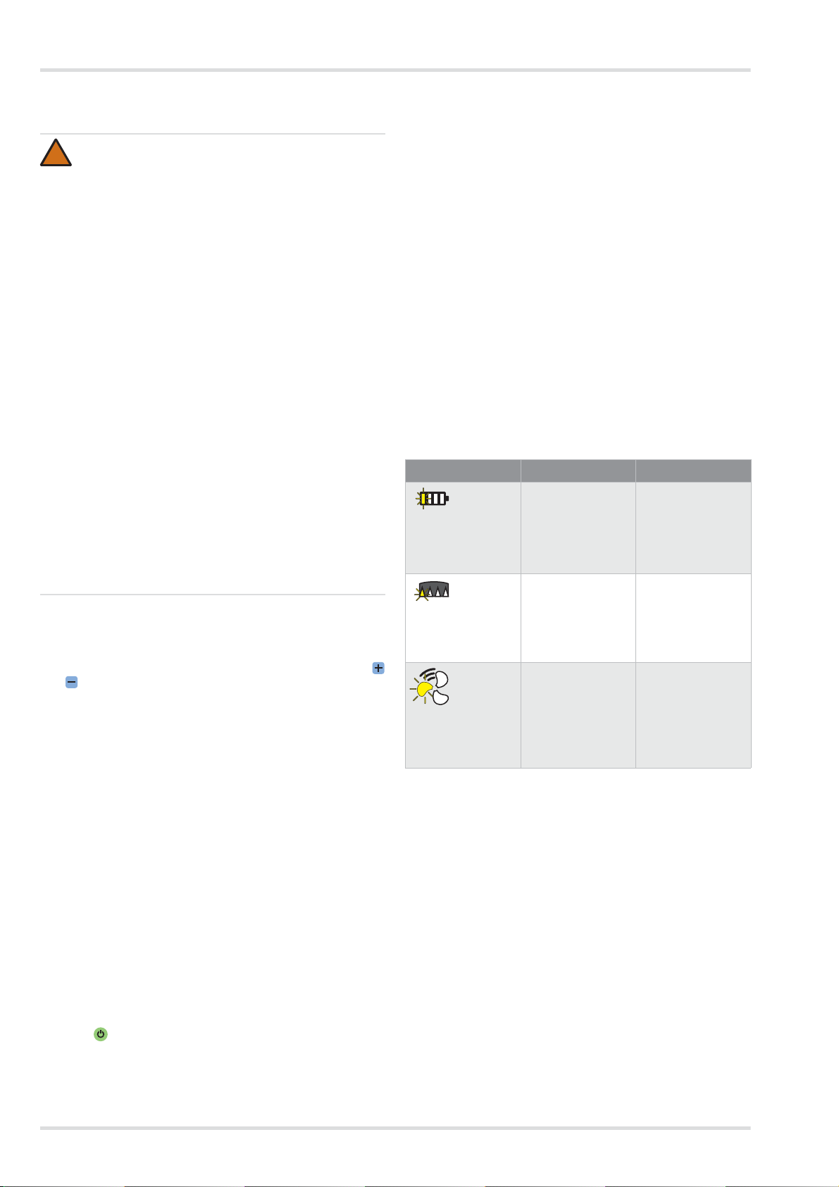
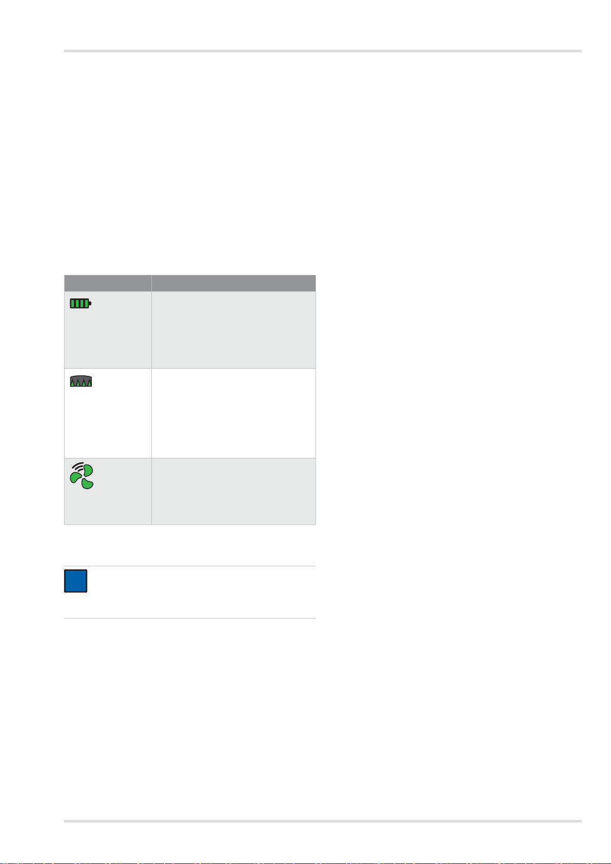
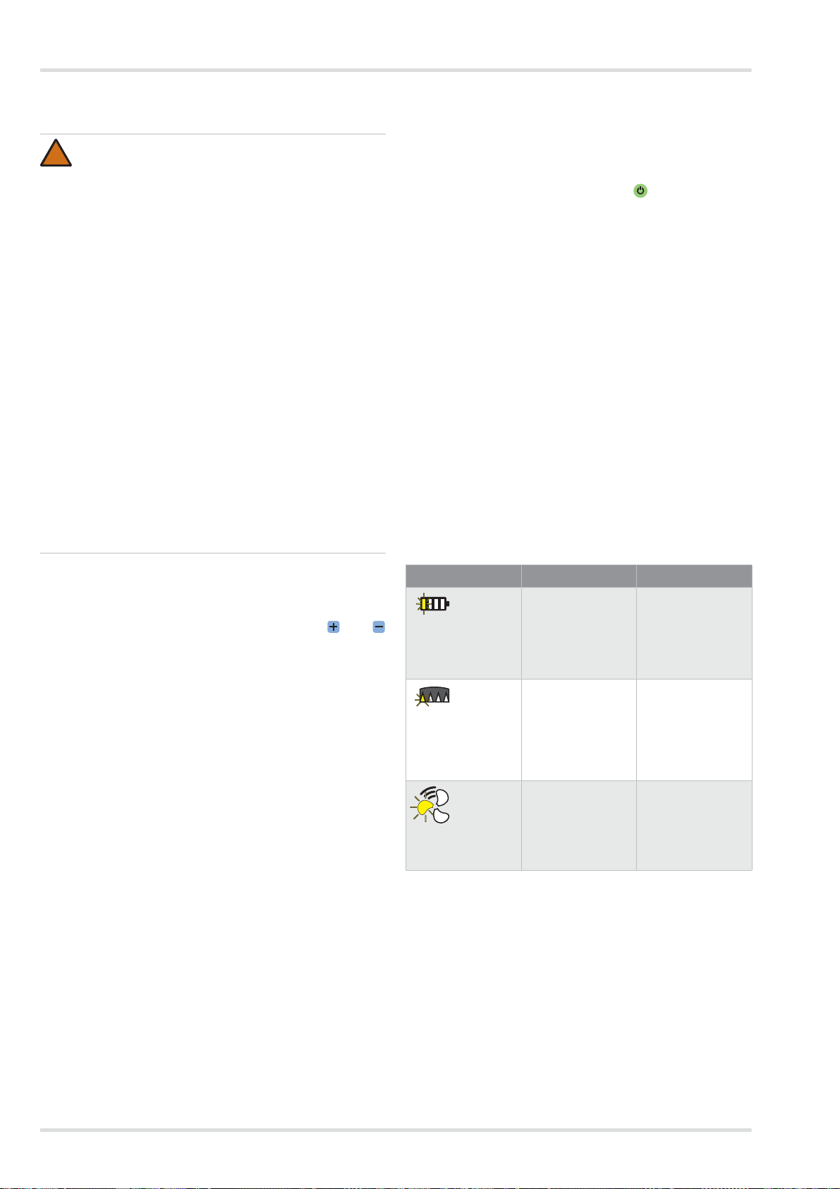
Anzeige Bedeutung
Segmente leuchten
grün.
Ladezustand je nach Anzahl der ange-
zeigten Segmente:
> 75 % (4 Segmente)
> 50 % (3 Segmente)
> 25 % (2 Segmente)
< 25 % (1 Segment)
Segmente leuchten
grün.
Restkapazität des Partikelfilters
1)
je
nach Anzahl der angezeigten Segmen-
te:
> 75 % (4 Segmente)
> 50 % (3 Segmente)
> 25 % (2 Segmente)
< 25 % (1 Segment)
1) Die Restkapazität des Gasfilters oder der Gasfilterkomponenten
des Kombinationsfilters kann nicht angezeigt werden.
Segmente leuchten
grün.
Stärke des Volumenstroms je nach An-
zahl der angezeigten Segmente:
Hoher Volumenstrom (3 Segmente)
Mittlerer Volumenstrom (2 Segmente)
Niedriger Volumenstrom (1 Segment)
HINWEIS
Warnungen oder Alarme werden durch gelb oder rot
blinkende LEDs angezeigt. Zur Bedeutung der Anzei-
gen bei Störungen siehe Kapitel 4 auf Seite 10.
i
i
8 Dräger X-plore 8000
Beschreibung
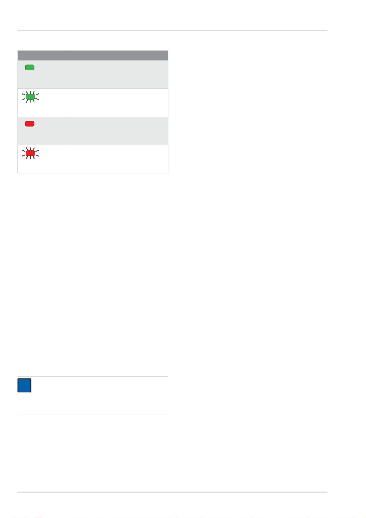
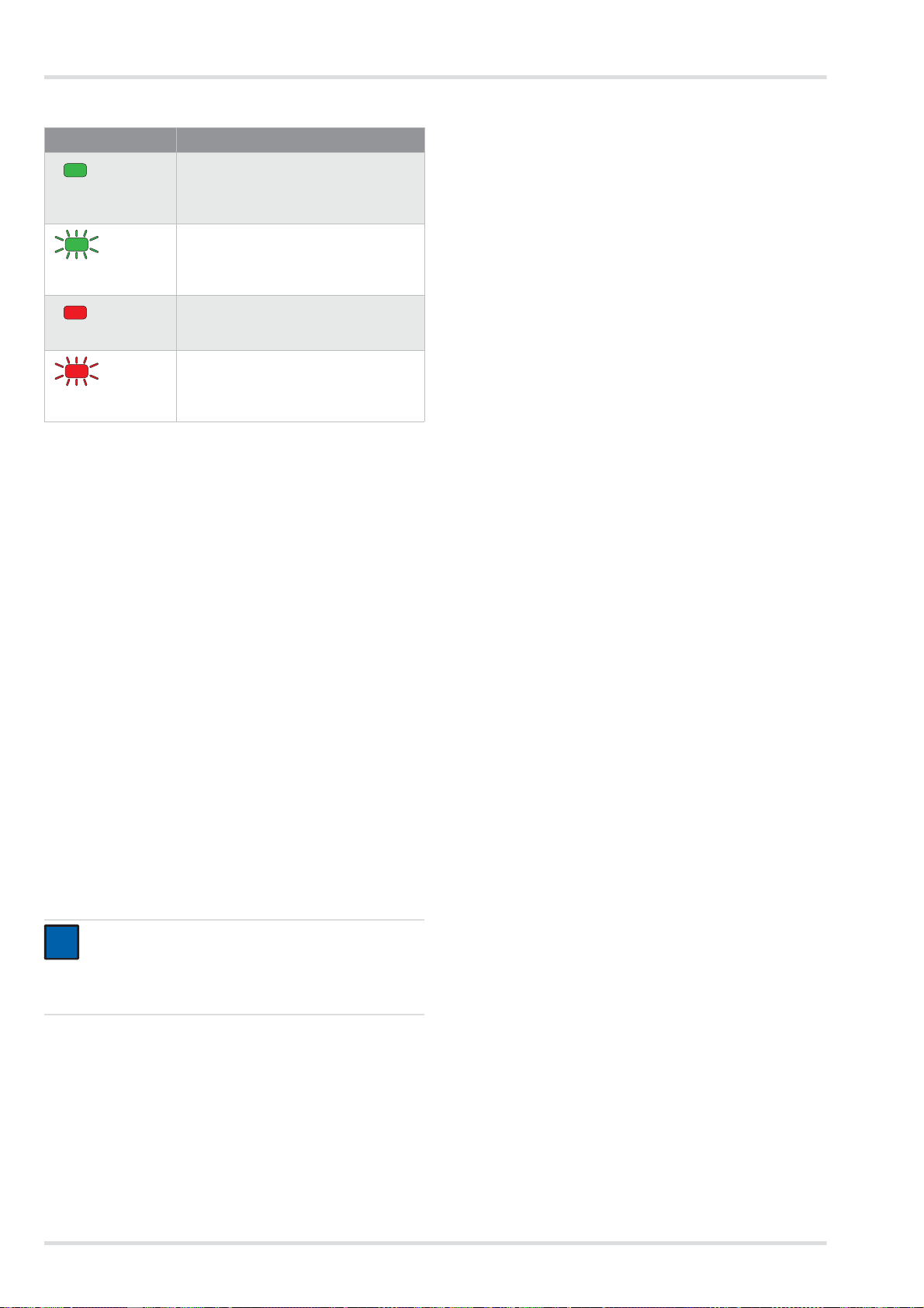
Bedeutung der Status-LED
Wenn der Akku vollständig geladen ist, schaltet das Ladegerät
automatisch in den Standby-Betrieb. Im Standby-Betrieb bleibt
der Akku immer vollständig aufgeladen. Hierbei wird der Akku
weder überladen noch beschädigt.
2.3 Funktionsbeschreibung
Das Gebläsefiltergerät ist ein umluftabhängiges Atemschutz-
gerät.
Es filtert Umgebungsluft und stellt sie als Atemluft zur Verfü-
gung. Hierzu saugt das Gerät permanent Umgebungsluft
durch das Filter an. Im Filter werden dem Filtertyp entspre-
chend schädliche Stoffe gebunden. Auf diese Weise wird die
Umgebungsluft aufbereitet und gelangt schließlich in den Ate-
manschluss. Dort steht sie als Atemluft bereit.
Ein kontinuierlicher Überdruck im Atemanschluss wirkt dem
Eindringen von Umgebungsluft entgegen.
2.3.1 Warneinrichtungen
Während des Gebrauchs auftretende Störungen werden durch
Warneinrichtungen angezeigt.
Zu den Warneinrichtungen gehören:
z Optischer Alarm (Anzeige am Bedienfeld)
z Akustischer Alarm
z Vibrationsalarm
Die Gebläseeinheit liefert immer den selben voreingestellten
Volumenstrom.
Wenn die Gebläseeinheit den voreingestellten Volumenstrom
in absehbarer Zeit nicht mehr halten kann (z. B. durch zuneh-
mende Sättigung des Partikelfilters), wird eine Warnung oder
ein Alarm ausgegeben.
2.4 Verwendungszweck
Je nach verwendetem Filtertyp schützt das Gerät vor Parti-
keln, Gasen und Dämpfen oder Kombinationen hieraus.
2.5 Einschränkungen des
Verwendungszwecks
Das Gerät ist nicht geeignet für die Verwendung:
z in explosionsgefährdeten Bereichen (Ex-Bereichen)
z bei Schadstoffen mit geringen Warneigenschaften (Ge-
ruch, Geschmack, Reizung der Augen und Atemwege)
z für Einsätze in unbelüfteten Behältern, Gruben, Kanälen
usw.
2.6 Zulassungen
Das Gerät ist zugelassen nach
z EN 12941:2009-02
z EN 12942:2009-02
Das Gerät erfüllt damit die Richtlinie über persönliche Schutz-
ausrüstung 89/686/EWG.
Weitere Richtlinien im Rahmen der CE-Kennzeichnung:
z EMV-Richtlinie (2004/108/EG)
z R&TTE-Richtlinie (1999/5/EG)
z NSR-Richtlinie (2006/95/EG)
z RoHS-Richtlinie (2011/65/EU)
2.7 Symbolerklärung und typidentische
Kennzeichnung
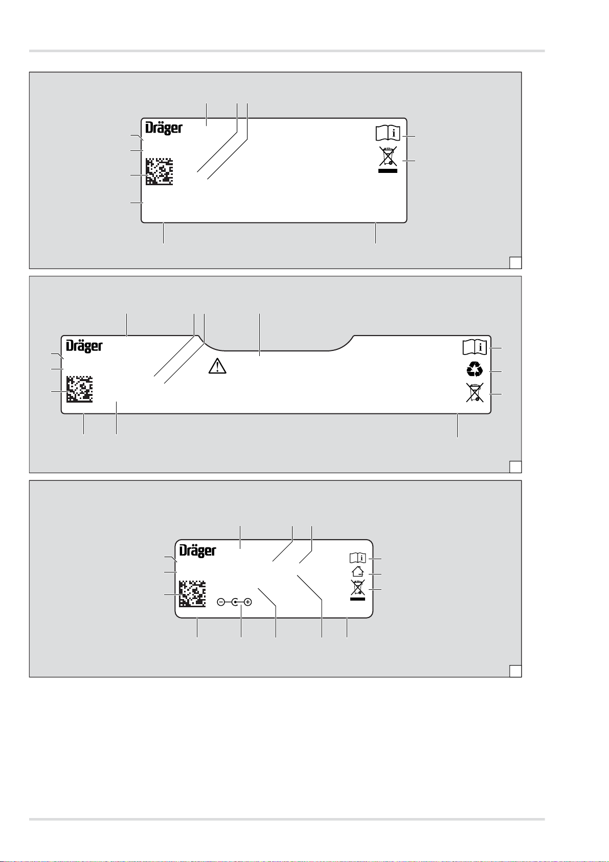
2.7.1 Typenschilder
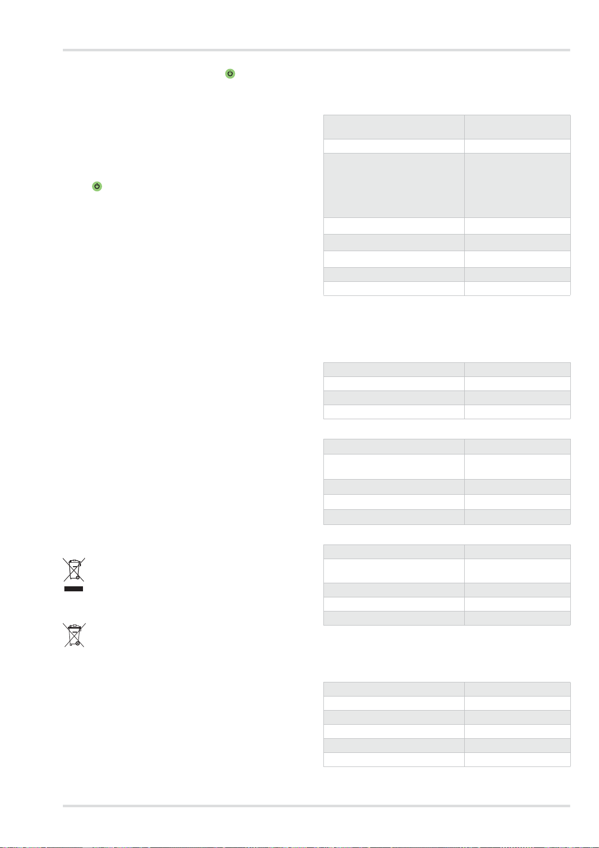
Ź Darstellung der Typenschilder auf Seite 4
1 Produktbezeichnung
2 Schutzart
3 Erfüllte EN-Normen
4 Symbol “Gebrauchsanweisung beach ten”
5 WEEE-Symbol “getrennte Sammlung von Elektro- und
Elektronikgeräten”
6 Produktionsland
7 Hersteller
8 CE-Kennzeichnung
9 DataMatrix-Code mit Teile- und Fabrikationsnummer
10 Fabrikationsnummer
11 Sachnummer
12 Verwendung nur im Haus, nicht im Freien
13 Maximale Umgebungstemperatur
14 Elektrische Daten
15 Steckerbelegung
16 Recycling-Symbol
17 Warnkennzeichnung
Anzeige Bedeutung
Status-LED leuchtet
grün.
Akku ist eingelegt und ist vollständig
geladen (Standby-Betrieb)
Status-LED blinkt
grün.
Akku ist eingelegt und wird geladen.
Status-LED leuchtet
rot.
Akku ist nicht eingelegt.
Status-LED blinkt
rot.
Störung
HINWEIS
Der Vibrationsalarm wird zusätzlich zum akustischen
Alarm ausgegeben. Je nach Dicke und Material der
Kleidung ist der Vibrationsalarm ggf. nicht wahrnehm-
bar.
i
i
Gebläseeinheit: Abbildung H
Standardladegerät: Abbildung I
Akku: Abbildung J
Gebrauch
Dräger X-plore 8000 9
Information zum Baujahr
Das Baujahr ergibt sich aus dem 3. Buchstaben der Fabrikati-
onsnummer: F = 2014, G = entfällt, H = 2015, I = entfällt, J =
2016, K = 2017 usw.
Beispiel: Fabrikationsnummer ARFH-0054: Der dritte Buchsta-
be ist F, also Baujahr 2014.
2.7.2 Verpackung
3 Gebrauch
3.1 Voraussetzungen für den Gebrauch
z Die Umgebungsverhältnisse (insbesondere Art und Kon-
zentration der Schadstoffe) müssen bekannt sein.
z Der Sauerstoffgehalt der Umgebungsluft darf nicht unter
folgende Grenzwerte sinken:
{ Mindestens 17 Vol.-% Sauerstoff in allen europäischen
Ländern außer den Niederlanden, Belgien und Groß-
britannien
{ Mindestens 19 Vol.-% Sauerstoff in den Niederlanden,
Belgien, Großbritannien, Australien und Neuseeland
{ Mindestens 19,5 Vol.-% Sauerstoff in den USA
In anderen Ländern nationale Richtlinien beachten.
3.2 Vorbereitungen für den Gebrauch
Außerhalb des Gefahrenbereichs folgende Tätigkeiten durch-
führen:
1. Komponenten des Gebläsefiltergeräts (Filter, Ateman-
schluss usw.) entsprechend der erforderlichen Schutzklas-
se und der Arbeitsaufgabe auswählen (siehe
Konfigurationsmatrix [Configuration Matrix] auf Seite 243).
2. Sichtprüfung durchführen (siehe Kapitel 5.3.1 auf Seite
11).
3. Ladezustand des Akkus prüfen (siehe Kapitel 5.3.3 auf
Seite 12).
4. Filter einsetzen (siehe Kapitel 5.3.4 auf Seite 12).
5. Tragesystem montieren (siehe Kapitel 3.2.1 auf Seite 9).
6. Ggf. Zubehörteile anbringen (siehe Kapitel 3.5 auf Seite
10).
7. Gerät anlegen (siehe Kapitel 3.2.2 auf Seite 9).
8. Atemanschluss anschließen (siehe Kapitel 3.2.3 auf Seite
9)
9. Gerät einschalten (siehe Kapitel 3.2.4 auf Seite 9).
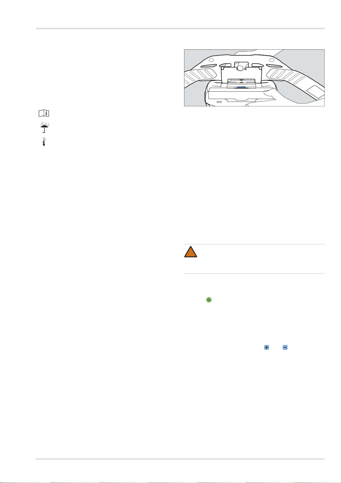
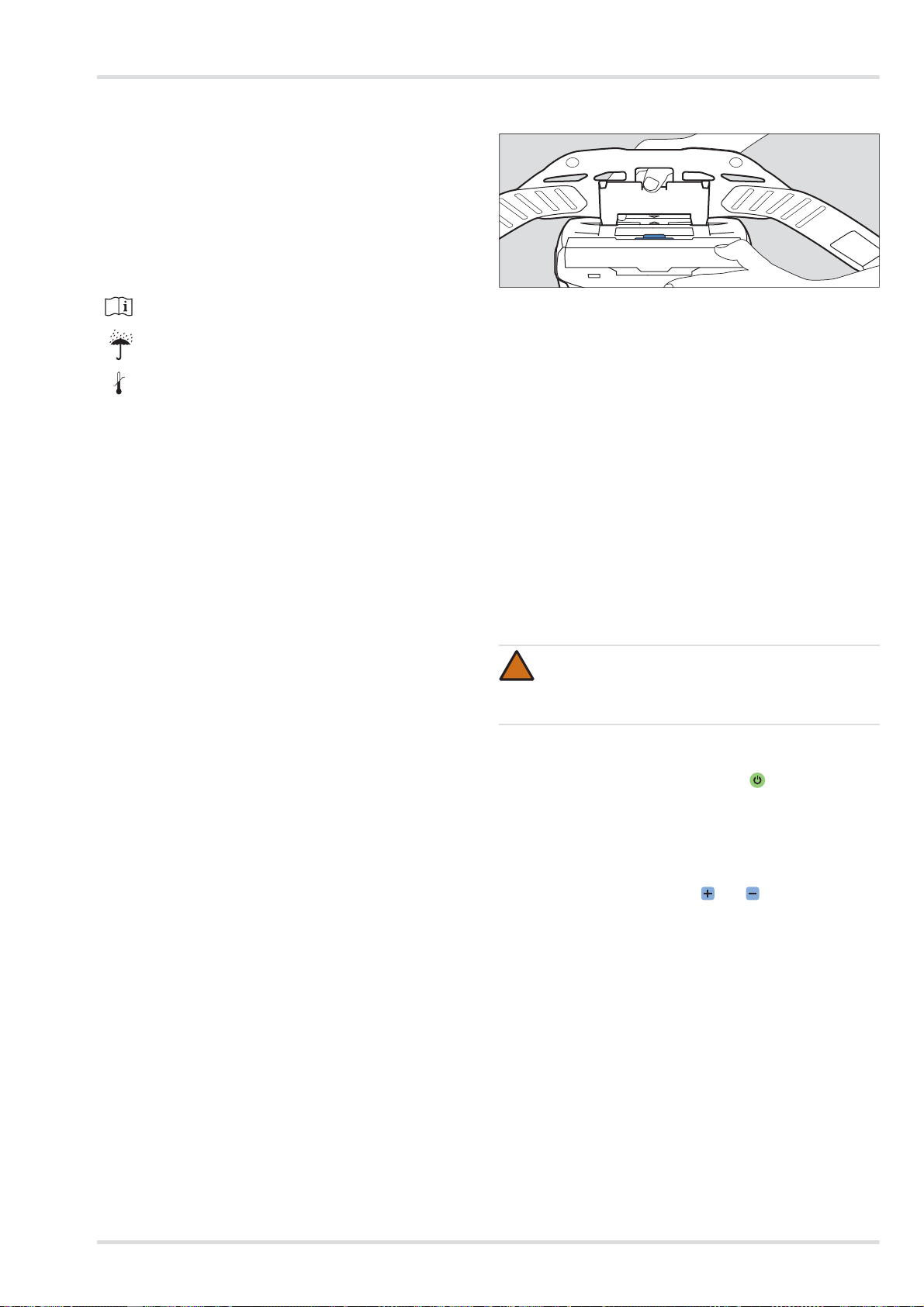
3.2.1 Tragesystem montieren
1. V erbindungsplatte des Tragesystems an der Aufnahme der
Gebläseeinheit ansetzen. Die Pfeilmarkierungen der Ver-
bindungsplatte und der Aufnahme müssen übereinstim-
men.
2. V erbindungsplatte herunterdrücken, bis sie an der Aufnah-
me hörbar einrastet.
3.2.2 Gerät anlegen
1. Gurt vom Tragesystem ungefähr auf benötigten Umfang
einstellen.
2. Gurt umlegen und Schnalle schließen. Das Gerät befindet
sich auf der Rückenseite des Anwenders.
3. Gurt straffen und überstehende Enden in den Gurtenden-
klammern fixieren.
3.2.3 Atemanschluss anschließen
1. S teckanschluss des Atemschlauchs an die Gebläseeinheit
anschließen.
2. Anderes Ende des Atemschlauchs mit dem Ateman-
schluss verbinden.
3.2.4 Gerät einschalten
1. Gebläseeinheit durch Drücken (ca. 2 Sekunden) der
Taste am Bedienfeld einschalten.
Nach dem Einschalten führt das Gerät einen Selbsttest
durch.
2. Wenn das Gerät nicht einwandfrei läuft oder Warneinrich-
tungen ansprechen, Störung beseitigen (siehe Kapitel 4
auf Seite 10).
3. Atemanschluss anlegen (siehe Gebrauchsanweisung des
entsprechenden Atemanschlusses).
4. Volumenstrom mit den Tasten und wie gewünscht
anpassen.
Gebrauchsanweisung beachten
Maximale Lagerluftfeuchte
Bereich der Lagertemperatur
<95%
-20°C
+70°C
WARNUNG
Eindringen von Umgebungsluft!
Vor dem Gebrauch sicherstellen, dass alle Komponen-
ten sicher und fest miteinander verbunden sind.
04733412.eps
!
10 Dräger X-plore 8000
Störungsbeseitigung
3.3 Während des Gebrauchs
3.3.1 Volumenstrom nachregulieren
Wenn erforderlich (z. B. bei erhöhter körperlicher Anstren-
gung), Volumenstrom während des Betriebs mit den Ta sten
und nachregulieren.
3.3.2 Warnungen und Alarme
Wenn eine Warnung ausgelöst wird, den Arbeitsbereich mit
Hinblick auf die mögliche Gefahrensituation zeitnah verlassen.
Um die Einsatzdauer bei Auftreten einer Warnung zu erhöhen,
Volumenstrom senken. (Nur möglich, wenn nicht bereits die
niedrigste Stufe ausgewählt ist.) Durch das Senken des Volu-
menstroms kann z. B. die Akkulaufzeit verlängert werden.
Wenn ein Alarm ausgelöst wird, den Arbeitsbereich ohne jede
Zeitverzögerung unmittelbar verlassen.
Nachdem eine Warnung oder ein Alarm ausgelöst wurde, die
Funktion des Geräts überprüfen (siehe Kapitel 4 auf Seite 10).
3.4 Nach dem Gebrauch
Folgende Tätigkeiten durchführen:
1. Gefahrenbereich verlassen.
2. Atemanschluss ablegen (siehe Gebrauchsanweisung des
entsprechenden Atemanschlusses).
3. Gebläseeinheit durch Drücken (ca. 2 Sekunden) der
Taste am Bedienfeld ausschalten.
4. Gurt des Tragesystems öffnen und Gerät abnehmen.
5. Gerät reinigen und desinfizieren (siehe Kapitel 5.2 auf Sei-
te 11)
3.5 Allgemeine Benutzeraufgaben
3.5.1 Komfortpolster für Standardgürtel anbringen
Komfortpolster mittels der Druckknöpfe mit dem Standardgür-
tel verbinden.
3.5.2 Gurtverlängerung am Tragesystem anbringen
Bei Bedarf Gurtverlängerung an der Schnalle des Gurtbands
anbringen.
4 Störungsbeseitigung
4.1 Warnungen
Die Art der Warnung wird optisch durch gelbes Blinken der ent-
sprechenden Anzeige signalisiert. Zusätzlich wird ein akusti-
sches Warnsignal ausgelöst und der Vibrationsalarm spricht
an.
WARNUNG
Gesundheitsgefährdung!
Gefahrenbereich umgehend verlassen bei:
z Abnehmender oder unterbrochener Luftversor-
gung (z. B. durch Ausfall des Gebläses)
Beim Atemanschlusstyp Haube/Helm/Schutzvisier
kann schnell ein Stau von Kohlendioxid oder Sau-
erstoffmangel auftreten. Außerdem kann schädli-
che Umgebungsluft in die Haube eindringen.
z Geruchs- oder Geschmacksentwicklung im Atem-
anschluss (Filterdurchbruch). Die Restkapazität
des Gasfilters oder der Gasfilterkomponenten des
Kombinationsfilters ist erschöpft.
z Benommenheit, Schwindel oder anderen Be-
schwerden
z Beschädigung des Geräts
z Sonstigen angezeigten Alarmen (siehe Kapitel 4
auf Seite 10)
Atemschläuche oder sonstige Komponenten bergen
die Gefahr des Hängenbleibens. Dies kann zur Be-
schädigung des Geräts und einer Unterbrechung der
Luftversorgung führen!
Beim Gebrauch des Geräts achtsam vorgehen.
Bei Verwendung des Atemanschlusstyps Haube/
Helm/Schutzvisier kann während des Einatmens bei
schwerer Arbeit Unterdruck entstehen und ungefilterte
Umgebungsluft eindringen!
Um dem entgegenzuwirken, Volumenstrom erhöhen.
!
Fehler Ursache Abhilfe
Ein Segment der
Ladezustandsan-
zeige des Akkus
blinkt gelb.
Restlaufzeit des
Akkus ist gering
(< 30 Minuten).
Akku in Kürze auf-
laden oder durch
vollständig gelade-
nen Akku ersetzen
(siehe Kapitel 5.3.3
auf Seite 12).
Ein Segment der
Restkapazitätsan-
zeige des Partikel-
filters blinkt gelb.
Restkapazität des
Partikelfilters ist
gering (< 20 %).
Partikel- oder
Kombinationsfilter
in Kürze wechseln
(siehe Kapitel 5.3.4
auf Seite 12).
Ein Segment der
Volumenstroman-
zeige blinkt gelb.
Störung beim Ein-
schalten (z. B.
durch fehlenden
Schlauch oder Fil-
ter).
Funktion des Ge-
räts überprüfen
und Gerät erneut
auf den Gebrauch
vorbereiten (siehe
Kapitel 3.2 auf Sei-
te 9).
Wartung
Dräger X-plore 8000 11
4.2 Alarme
Die Art des Alarms wird optisch durch rotes Blinken der ent-
sprechenden Anzeige signalisiert. Zusätzlich wird ein akusti-
sches Alarmsignal ausgelöst und der Vibrationsalarm spricht
an.
5 Wartung
5.1 Instandhaltungsintervalle
5.2 Reinigung und Desinfektion
5.2.1 Gerät reinigen und desinfizieren
1. Gerät demontieren:
a. Atemschlauch, Atemanschluss und Gebläseeinheit
voneinander trennen.
b. Tragesystem von der Gebläseeinheit trennen.
c. Wenn vorhanden, Zubehör (z. B. Schlauch- und Ge-
rätehüllen) demontieren.
d. Spritzschutzdeckel und Filter demontieren (siehe Kapi-
tel 5.3.4 auf Seite 12).
2. Atemanschluss gemäß entsprechender Gebrauchsanwei-
sung reinigen.
3. Atemschlauch und Tragesystem reinigen:
a. Alle Teile mit lauwarmem Wasser unter Zusatz von Se-
kusept
®
Cleaner
1)
und einem weichen Lappen reinigen
(Temperatur: max. 30 °C, Konzentration je nach Ver-
schmutzungsgrad: 0,5 - 1 %).
b. Alle Teile unter fließendem Wasser gründlich spülen.
c. Ein Desinfektionsbad aus Wasser und Incidin
®
Rapid
2)
vorbereiten (Temperatur: max. 30 °C, Konzentration:
1,5 %).
d. Alle Teile, die desinfiziert werden müssen, in das Des-
infektionsbad einlegen (Dauer: 15 Minuten).
e. Alle Teile unter fließendem Wasser gründlich spülen.
f. Alle Teile an der Luft oder im Trockenschrank trocknen
lassen (Temperatur: max. 60 °C). Vor direkter Sonne-
neinstrahlung schützen.
4. Gebläseeinheit und Spritzschutzdeckel mit Incides
®
N
Desinfektionstüchern
1)
reinigen und desinfizieren.
Bei starker Verschmutzung kann die Gebläseeinheit wie folgt
unter fließendem Wasser abgespült werden.
1. Sicherstellen, dass der Akku eingesetzt bleibt. In das Ak-
kufach darf kein Wasser gelangen.
2. Ansaugöffnung und Schlauchanschluss mit Verschluss-
kappen (als Zubehör erhältlich) verschließen.
5.3 Wartungsarbeiten
5.3.1 Sichtprüfung durchführen
Alle Teile gründlich prüfen und ggf. beschädigte Teile aus-
wechseln. Insbesondere die Filterdichtfläche an der Gebläse-
einheit auf Beschädigungen (z. B. Kratzer) oder
Verschmutzungen prüfen.
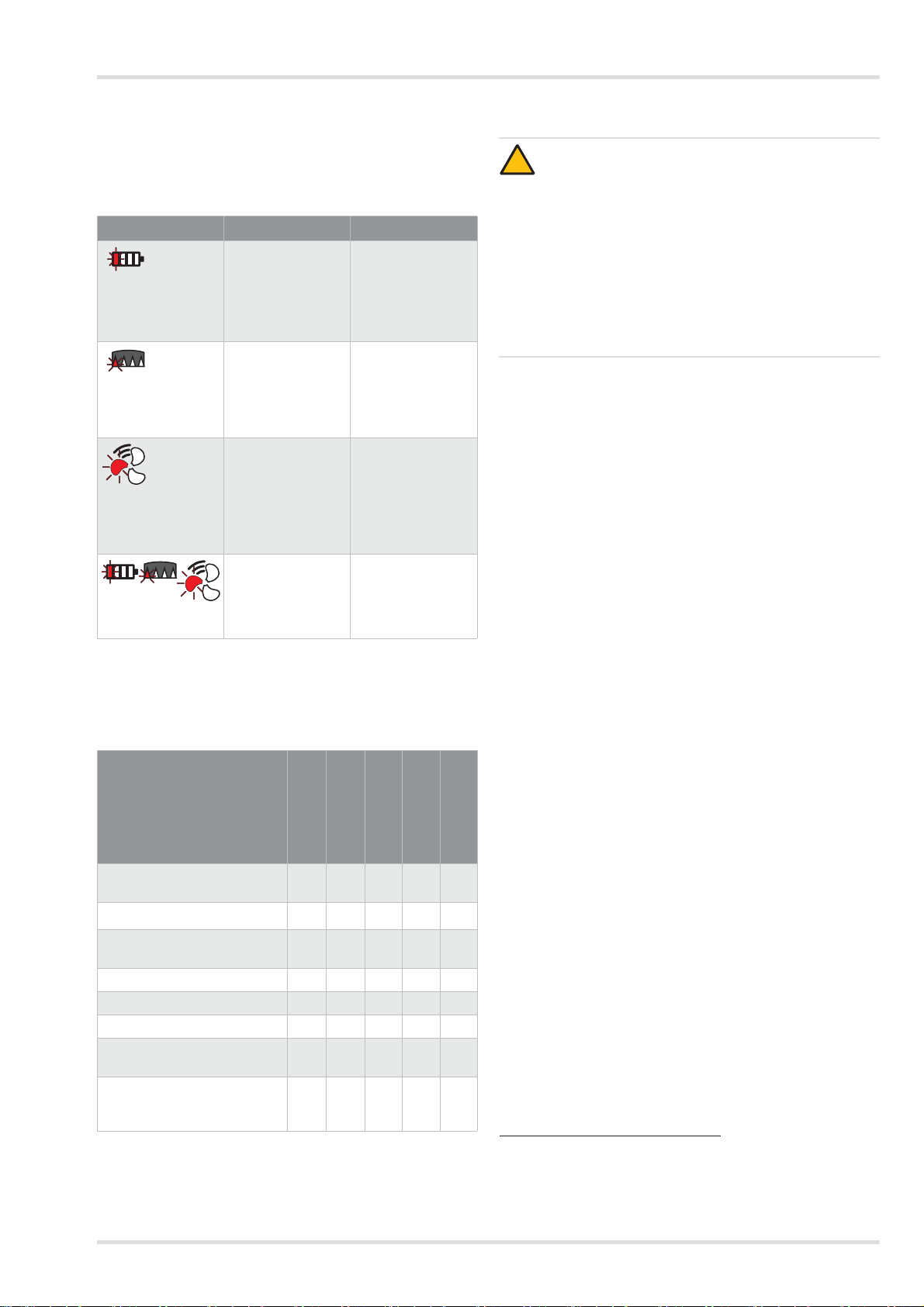
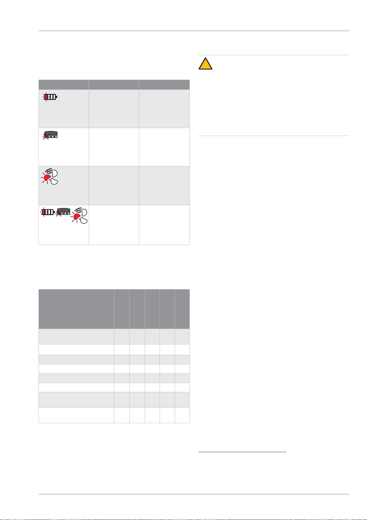
Fehler Ursache Abhilfe
Ein Segment der
Ladezustandsan-
zeige des Akkus
blinkt rot.
Restlaufzeit des
Akkus fast er-
schöpft
(< 10 Minuten)
Akku aufladen
oder durch voll-
ständig geladenen
Akku ersetzen (sie-
he Kapitel 5.3.3 auf
Seite 12).
Ein Segment der
Restkapazitätsan-
zeige des Partikel-
filters blinkt rot.
Restkapazität des
Partikelfilters fast
erschöpft (< 10 %)
Partikel- oder
Kombinationsfilter
wechseln (siehe
Kapitel 5.3.4 auf
Seite 12).
Ein Segment der
Volumenstroman-
zeige blinkt rot.
Fehlerhafte Atem-
luftversorgung
während des Be-
triebs (z. B. durch
fehlenden
Schlauch oder Fil-
ter).
Funktion des Ge-
räts überprüfen
und Gerät erneut
auf den Gebrauch
vorbereiten (siehe
Kapitel 3.2 auf Sei-
te 9).
Jeweils ein Seg-
ment blinkt rot.
Allgemeiner Sys-
temfehler
Gerät durch Drä-
ger Service über-
prüfen lassen.
Durchzuführende Arbeiten
Vor Gebrauch
Nach Gebrauch
Jährlich
Alle 2 Jahre
Bei Bedarf
Gerät reinigen und desinfizie-
ren
X
X
1)
1) bei luftdicht verpackten Geräten, sonst halbjährlich
Sichtprüfung durchführen X
X
1)
Ladezustand des Akkus prü-
fen
X
Akku wechseln X
Akku laden X
Filter wechseln X
Volumenstrom und Warnein-
richtungen prüfen
X
O-Ring am Steck- oder Bajo-
nettanschluss der Schläuche
wechseln
X X
VORSICHT
Mögliche Beschädigung von Bauteilen!
Zum Reinigen und Desinfizieren nur die beschriebenen
Verfahren anwenden und die genannten Reinigungs-
und Desinfektionsmittel verwenden. Andere Mittel und
Verfahren, Dosierungen und Einwirkzeiten können
Bauteile beschädigen.
Gesundheitsgefährdung!
Die unverdünnten Mittel sind bei direktem Kontakt mit
Augen oder Haut gesundheitsschädlich. Beim Arbeiten
mit diesen Mitteln Schutzbrille und Schutzhandschuhe
tragen.
1) Sekusept
®
und Incides
®
sind eingetragene Marken der Ecolab
Deutschland GmbH.
2) Incidin
®
ist eine eingetragene Marke der Ecolab USA Inc.
!
12 Dräger X-plore 8000
Wartung
5.3.2 Ladezustand des Akkus prüfen
1. Am Akku die Taste zum Anzeigen des Ladezustands betä-
tigen.
2. Ladezustandsanzeige ablesen.
3. Wenn der Ladezustand nicht für die geplante Einsatzdauer
ausreicht:
Akku wechseln oder laden (siehe Kapitel 5.3.3 auf Seite
12).
5.3.3 Akku wechseln oder laden
Akku abnehmen:
1. Ggf. Tragesystem hochklappen.
2. Akkuverriegelungstaste betätigen. Darauf achten, dass der
Akku nicht herunterfällt.
3. Akku entnehmen.
Akku einsetzen:
1. Ggf. Tragesystem hochklappen.
2. Akku zunächst schräg in das Akkufach setzen und dann hi-
neinklappen, so dass er hörbar einrastet.
Akku laden:
1. Korrekte Netzspannung der Stromversorgung überprüfen.
Die Betriebsspannung des Netzteils muss mit der Netz-
spannung übereinstimmen.
2. Ladegerät mit dem Netzteil verbinden.
3. Netzteil an die Stromversorgung anschließen.
4. Akku zunächst schräg in das Ladegerät setzen und dann
hineinklappen, so dass er hörbar einrastet.
5. Ladevorgang abwarten.
6. Wenn der Akku vollständig geladen ist, Akkuverriegelungs-
taste betätigen und Akku herausnehmen.
7. Netzteil von der Stromversorgung und Ladegerät vom
Netzteil trennen.
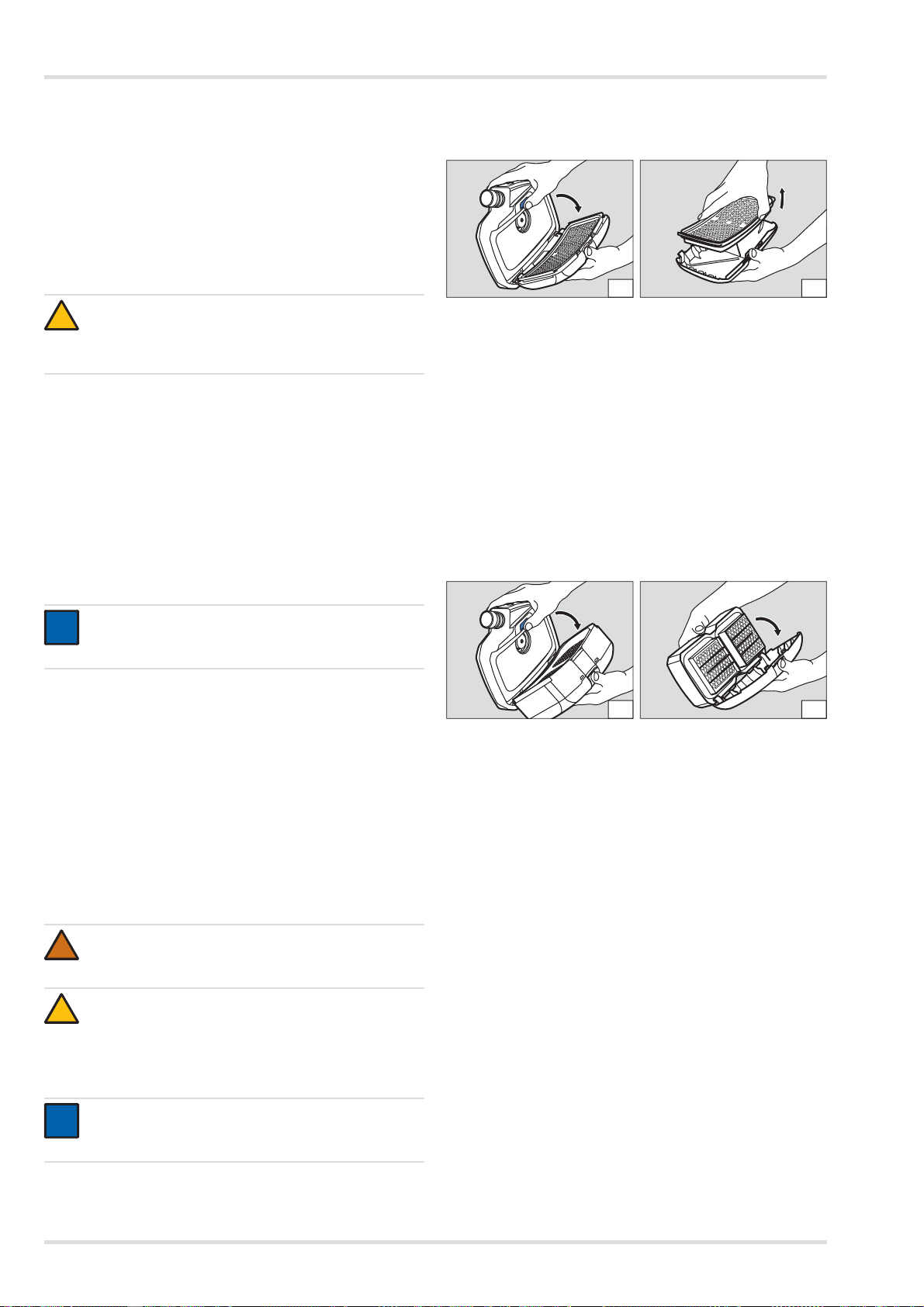
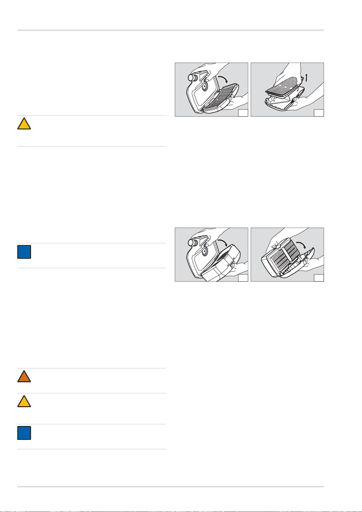
5.3.4 Filter wechseln
Partikelfilter
Filter abnehmen:
1. Filterverriegelungstaste betätigen.
2. Filter zusammen mit dem Spritzschutzdeckel herausklap-
pen (Abbildung A).
3. Verbrauchtes Filter entnehmen (Abbildung B).
Filter einsetzen:
1. Gummidichtung am Filter auf Beschädigungen überprüfen.
2. Neuen Filter in den Spritzschutzdeckel einsetzen.
3. Filter zusammen mit dem Spritzschutzdeckel schräg in die
Gebläseeinheit einsetzen.
4. Filter mit dem Spritzschutzdeckel hineinklappen, so dass
er hörbar einrastet.
Gas- oder Kombinationsfilter
Filter abnehmen:
1. Filterverriegelungstaste betätigen.
2. Filter zusammen mit dem Spritzschutzdeckel herausklap-
pen (Abbildung A).
3. Spritzschutzdeckel demontieren:
a. Mittig auf die obere Kante des Spritzschutzdeckels drü-
cken, so dass er ausrastet.
b. Spritzschutzdeckel herausklappen (Abbildung B).
Filter einsetzen:
1. Gummidichtung am Filter auf Beschädigungen überprüfen.
2. Spritzschutzdeckel mit der unteren Kante schräg auf das
Filter stecken.
3. Spritzschutzdeckel aufdrücken, so dass er hörbar einras-
tet.
4. Filter zusammen mit dem Spritzschutzdeckel schräg in die
Gebläseeinheit einsetzen.
5. Filter mit dem Spritzschutzdeckel hineinklappen, so dass
er hörbar einrastet.
5.3.5 Vo lu menstrom und Warneinrichtungen prüfen
1. Sicherstellen, dass ein Filter eingesetzt ist (siehe Kapitel
5.3.4 auf Seite 12).
2. S teckanschluss des Atemschlauchs an die Gebläseeinheit
anschließen.
VORSICHT
Beschädigung des Akkus durch Kurzschluss!
Den Akku immer so ablegen, dass die Kontakte nicht
mit Metall in Berührung kommen.
HINWEIS
Das Ladegerät immer von der Stromversorgung tren-
nen, wenn es nicht gebraucht wird.
WARNUNG
Ohne Filter keine Schutzwirkung!
Gerät nicht ohne Filter verwenden.
VORSICHT
Beschädigung der Gebläseeinheit durch Eindringen
von Partikeln!
Beim Abnehmen des Filters darauf achten, dass über
die Ansaugöffnung keine Partikel in das Gerät gelan-
gen.
HINWEIS
Je nach verwendetem Filtertyp unterscheidet sich der
Ablauf beim Wechseln des Filters.
!
i
i
!
!
i
i
02633412.eps
A
02733412.eps
B
B
02933412.eps
02833412.eps
A
Transport
Dräger X-plore 8000 13
3. Gebläseeinheit durch Drücken der Taste am Bedienfeld
einschalten.
Nach dem Einschalten führt das Gerät einen Selbsttest
durch. Wenn das Gerät nicht einwandfrei läuft oder War-
neinrichtungen ansprechen, Störung beseitigen (siehe Ka-
pitel 4 auf Seite 10).
4. Offenes Ende des Atemschlauchs mit der Handfläche ab-
decken.
Die Gebläseeinheit beginnt nach ca. 5 Sekunden intensi-
ver zu laufen. Nach ca. 20 Sekunden wird ein Alarm aus-
gelöst.
Wenn das Gebläse die Drehzahl nicht verändert und kein
Alarm ausgelöst wird, Gebläseeinheit überprüfen lassen.
5. Wenn gewünscht, Gebläseeinheit durch erneutes Drücken
der Taste am Bedienfeld wieder ausschalten.
5.3.6 O-Ring am Steck- oder Bajonettanschluss der
Schläuche wechseln
1. Alten O-Ring mit dem O-Ring-Entferner an der Kerbe her-
aushebeln.
2. Neuen O-Ring in die vorgesehene Nut einsetzen.
6 Transport
Transport in der Originalverpackung oder in optional erhältli-
cher Transportbox.
7 Lagerung
Gesamtsystem lagern:
z Filter und Akku ausbauen.
z Komponenten in einem Behälter oder Schrank trocken und
schmutzfrei aufbewahren und vor direkter Sonnen- und
Wärmestrahlung schützen.
Akkus lagern:
z Stark entladene Akkus können bei längerer Lagerung be-
schädigt werden. Vor der Lagerung Akkus auf 50 bis 70 %
aufladen.
z Bei einer Lagerung von mehr als 6 Monaten Akkus zwi-
schenzeitlich aufladen.
z Akkus nicht längere Zeit außerhalb des empfohlenen Tem-
peraturbereichs lagern. Dies kann die verb leibende Kapa-
zität und die Anzahl der möglichen Ladezyklen vermindern.
8Entsorgung
9 Technische Daten
Gesamtes System
Akkus
Standardakku
Langzeitakku
Ladegerät
Dieses Produkt darf nicht als Siedlungsabfall entsorgt
werden. Es ist daher mit dem nebenstehenden Symbol
gekennzeichnet.
Dräger nimmt dieses Produkt kostenlos zurück. Infor-
mationen dazu geben die nationalen Vertriebsorgani-
sationen und Dräger.
Batterien und Akkus dürfen nicht als Siedlungsabfall
entsorgt werden. Sie sind daher mit dem
nebenstehenden Symbol gekennzeichnet. Batterien
und Akkus gemäß den geltenden Vorschriften bei
Batterie-Sammelstellen entsorgen.
Volumenstrom Atems chutzhaube/
-helm/-visier:
170/190/210 L/min
Volumenstrom Halb-/Vollmaske: 115/130/145 L/min
Nenneinsatzdauer: 4 Stunden
mit Standardakku
8 Stunden
mit Langzeitakku
Arbeitstemperatur:
1)
1) Ladegerät und Akkus siehe separate Angaben in diesem Kapitel.
Andere Komponenten siehe entsprechende Gebrauchsanwei-
sung.
-10 °C bis 60 °C
Arbeits-/Lagerluftfeuchte:
1)
95 % relative Feuchte
Lagertemperatur:
1)
-20 °C bis 60 °C
Geräuschpegel: ca. 64 dB(A)
Schutzart: IP 65
Arbeitstemperatur: -10 °C bis 60 °C
Arbeits-/Lagerluftfeuchte: 95 % relative Feuchte
Lagertemperatur: -20 °C bis 50 °C
Ladetemperatur: 0 °C bis 50 °C
Ladedauer: < 4 Stunden
Betriebsdauer nach einer Aufla-
dung:
ca. 4 Stunden
1)
Nennspannung: 10,8 V
Nennkapazität: 3,35 Ah
Leistungsabgabe: 36 Wh
Ladedauer: < 4 Stunden
Betriebsdauer nach einer Aufla-
dung:
ca. 8 Stunden
1)
1) Variiert je nach eingestelltem Volumenstrom sowie verwendetem
Filter- und Atemanschlusstyp
Nennspannung: 10,8 V
Nennkapazität: 6,70 Ah
Leistungsabgabe: 72 Wh
Eingangsspannung: 15 V
Eingangsstrom: 4A
Ausgangsspannung: 9 - 12,6 V
Ausgangsstrom: 4A
Schutzart: IP 30

14 Dräger X-plore 8000
Bestellliste
10 Bestellliste
Komponenten
Zubehörteile
Ersatzteile
Reinigungs- und Desinfektionsmittel
Arbeitstemperatur: 0 °C bis 50 °C
Arbeits-/Lagerluftfeuchte: 95 % relative Feuchte
Lagertemperatur: -20 °C bis 50 °C
Pos.
1)
Benennung und Beschreibung Bestellnr.
1 Dräger X-plore 8500 (IP) R59500
2 Dräger X-plore 8000 Standardakku R59565
3 Dräger X-plore 8000 Langzeitakku R59585
4 Dräger X-plore 8000 Standardgürtel R59700
5 Dräger X-plore 8000 Gürtel, dekontami-
nierbar
R59710
6 Dräger X-plore 8000 Standardschlauch
(für Halb-/Vollmasken)
R59630
7 Dräger X-plore 8000 Standardschlauch
(für Hauben)
R59620
8 Dräger X-plore 8000 Standardschlauch
(für Helme und Visiere)
R59640
9 Dräger X-plore 8000 Flexibler Schlauch
(für Halb-/Vollmasken)
R59610
10 Dräger X-plore 8000 Flexibler Schlauch
(für Hauben)
R59600
11 Dräger X-plore 8000 Flexibler Schlauch
(für Helme und Schutzvisiere)
R59650
12 Dräger X-plore 8000 Filter P R SL 6739535
13 Dräger X-plore 8000 Filter A2 6739580
14 Dräger X-plore 8000 Filter A2 P R SL 6739545
15 Dräger X-plore 8000 Filter A1B1E1K1
Hg P R SL
6739555
16 Dräger X-plore 8000 Standardhaube,
kurz (S/M)
R59800
17 Dräger X-plore 8000 Standardhaube,
kurz (L/XL)
R59810
18 Dräger X-plore 8000 Standardhaube,
lang (S/M)
R59820
19 Dräger X-plore 8000 Standardhaube,
lang (L/XL)
R59830
20 Dräger X-plore 8000 Premiumhaube,
kurz (S/M)
R59840
21 Dräger X-plore 8000 Premiumhaube,
kurz (L/XL)
R59850
22 Dräger X-plore 8000 Premiumhaube,
lang (S/M)
R59860
23 Dräger X-plore 8000 Premiumhaube,
lang (L/XL)
R59870
24 Dräger X-plore 8000 Helm mit Visier,
schwarz
R58325
25 Dräger X-plore 8000 Helm mit Visier,
weiß
R59910
26 Dräger X-plore 8000 Schutzvisier R59900
27 Dräger X-plore 6300 EPDM/PMMA R55800
28 Dräger X-plore 6530 EPDM/PC R55795
29 Dräger X-plore 6570 SI/PC R55790
30 Dräger X-plore 4740 SI S/M R55875
31 Dräger X-plore 4740 SI M/L R55874
32 Dräger FPS 7000 EPDM-S1-PC-CR R56502
33 Dräger FPS 7000 EPDM-M2-PC-CR R56310
34 Dräger FPS 7000 EPDM-L2-PC-CR R56503
35 Dräger X-plore 8000 Standardladegerät R59580
1) Siehe Konfigurationsmatrix (Configuration Matrix) auf Seite 243.
Pos.
1)
1) Siehe Konfigurationsmatrix (Configuration Matrix) auf Seite 243.
Benennung und Beschreibung Bestellnr.
36 Dräger X-plore 8000 Verschlussstopfen
(für Schlauchanschluss der Gebläseein-
heit)
R59563
37 Dräger X-plore 8000 Verschlussstopfen
(für Ansaugöffnung der Gebläseeinheit)
R59564
38 Dräger X-plore 8000 Komfortpolster R59730
39 Gurtverlängerung für X-plore 8000
Standardgürtel, 35 cm
R59750
40 Gurtverlängerung für X-plore 8000 Gür-
tel,dekontaminierbar, 35 cm
R59760
41 Dräger X-plore 8000 Aufbewahrungs-
box
R59690
Pos. Benennung und Beschreibung Bestellnr.
42 Dräger X-plore 8000 Spritzschutzdeckel 6739725
43 Gurtendenklammern, Set R59705
44 Steckschnalle, Set R59715
45 O-Ring für Steckanschluss X-plore 8000
Haube und Gebläseeinheit
R59631
46 O-Ring für Bajonettanschluss X-plore
8000 Helm und Schutzvisier
R59632
47 O-Ring-Entferner R21402
Pos. Benennung und Beschreibung Bestellnr.
48
Sekusept
®
Cleaner, 4 x 2 L
7904071
49
Incidin
®
Rapid, 6 L
andere Gebinde auf Anfrage
R61880
50
Incides
®
N Desinfektionstücher,
6 Dosen a 90 Tücher
6570001
Pos.
1)
Benennung und Beschreibung Bestellnr.

Contents
Dräger X-plore® 8000 15
Contents
1 For your safety . . . . . . . . . . . . . . . . . . . . . . . . . . .16
1.1 General safety statements . . . . . . . . . . . . . . . . . . .16
1.2 Definitions of alert icons . . . . . . . . . . . . . . . . . . . . .16
2 Description . . . . . . . . . . . . . . . . . . . . . . . . . . . . . .16
2.1 System overview . . . . . . . . . . . . . . . . . . . . . . . . . . .16
2.2 Components . . . . . . . . . . . . . . . . . . . . . . . . . . . . . .16
2.2.1 Fan unit . . . . . . . . . . . . . . . . . . . . . . . . . . . . . . . . . .16
2.2.2 Filter and facepieces . . . . . . . . . . . . . . . . . . . . . . . .17
2.2.3 Breathing hoses . . . . . . . . . . . . . . . . . . . . . . . . . . .17
2.2.4 Carrying systems . . . . . . . . . . . . . . . . . . . . . . . . . .17
2.2.5 Rechargeable batteries . . . . . . . . . . . . . . . . . . . . . .17
2.2.6 Battery chargers . . . . . . . . . . . . . . . . . . . . . . . . . . .17
2.3 Functional description . . . . . . . . . . . . . . . . . . . . . . .18
2.3.1 Warning devices . . . . . . . . . . . . . . . . . . . . . . . . . . .18
2.4 Intended use . . . . . . . . . . . . . . . . . . . . . . . . . . . . . .18
2.5 Limitations on use . . . . . . . . . . . . . . . . . . . . . . . . . .18
2.6 Approvals . . . . . . . . . . . . . . . . . . . . . . . . . . . . . . . .18
2.7 Explanation of type-identifying marking and
symbols . . . . . . . . . . . . . . . . . . . . . . . . . . . . . . . . . .18
2.7.1 Name plates . . . . . . . . . . . . . . . . . . . . . . . . . . . . . .18
2.7.2 Packaging . . . . . . . . . . . . . . . . . . . . . . . . . . . . . . . .19
3 Use . . . . . . . . . . . . . . . . . . . . . . . . . . . . . . . . . . . . .19
3.1 Preconditions for use . . . . . . . . . . . . . . . . . . . . . . .19
3.2 Preparations for use . . . . . . . . . . . . . . . . . . . . . . . .19
3.2.1 Assembling the carrying system . . . . . . . . . . . . . . .19
3.2.2 Donning the device . . . . . . . . . . . . . . . . . . . . . . . . .19
3.2.3 Connecting the facepiece . . . . . . . . . . . . . . . . . . . .19
3.2.4 Switching on the device . . . . . . . . . . . . . . . . . . . . . 19
3.3 During use . . . . . . . . . . . . . . . . . . . . . . . . . . . . . . . .20
3.3.1 Adjusting the flow rate . . . . . . . . . . . . . . . . . . . . . . .20
3.3.2 Warnings and alarms . . . . . . . . . . . . . . . . . . . . . . .20
3.4 After use . . . . . . . . . . . . . . . . . . . . . . . . . . . . . . . . .20
3.5 General user tasks . . . . . . . . . . . . . . . . . . . . . . . . . 2 0
3.5.1 Attaching comfortable padding for standard belt . .2 0
3.5.2 Attaching belt extension to carrying system . . . . . .20
4 Troubleshooting . . . . . . . . . . . . . . . . . . . . . . . . . .20
4.1 Warnings . . . . . . . . . . . . . . . . . . . . . . . . . . . . . . . . .20
4.2 Alarms . . . . . . . . . . . . . . . . . . . . . . . . . . . . . . . . . . .21
5 Maintenance . . . . . . . . . . . . . . . . . . . . . . . . . . . . .21
5.1 Maintenance intervals . . . . . . . . . . . . . . . . . . . . . . .21
5.2 Cleaning and disinfecting . . . . . . . . . . . . . . . . . . . .21
5.2.1 Clean and disinfect the device . . . . . . . . . . . . . . . .21
5.3 Maintenance work . . . . . . . . . . . . . . . . . . . . . . . . . .21
5.3.1 Visual inspection . . . . . . . . . . . . . . . . . . . . . . . . . . .21
5.3.2 Checking the battery capacity . . . . . . . . . . . . . . . . .22
5.3.3 Replacing or charging the rechargeable battery . . .22
5.3.4 Replacing the filter . . . . . . . . . . . . . . . . . . . . . . . . .22
5.3.5 Checking the flow rate and warning devices . . . . . .22
5.3.6 Replacing the O-ring at plug-in or bayonet-type hose
connector . . . . . . . . . . . . . . . . . . . . . . . . . . . . . . . .23
6 Transport . . . . . . . . . . . . . . . . . . . . . . . . . . . . . . . 23
7 Storage . . . . . . . . . . . . . . . . . . . . . . . . . . . . . . . . . 23
8 Disposal . . . . . . . . . . . . . . . . . . . . . . . . . . . . . . . . 23
9 Technical data . . . . . . . . . . . . . . . . . . . . . . . . . . . 23
10 Order list . . . . . . . . . . . . . . . . . . . . . . . . . . . . . . . 24
16 Dräger X-plore 8000
For your safety
1 For your safety
1.1 General safety statements
z Before using this product, carefully read these Instructions
for Use and those of the associated components.
z Strictly follow the Instructions for Use. The user must fully
understand and strictly observe the instructions. Use the
product only for the purposes specified in the Intended use
section of this document.
z Do not dispose of the Instructions for Use. Ensure that they
are retained and appropriately used by the product user.
z Only trained and competent users are permitted to use this
product.
z Follow the local and national guidelines pertaining to this
product.
z Only trained and competent personnel are permitted to in-
spect, repair and service the product.
z Use only genuine Dräger spare parts and accessories, or
the proper functioning of the product may be imp aired.
z Do not use a faulty or incomplete product. Do not modify
the product.
z Notify Dräger in the event of any product or component
fault or failure.
1.2 Definitions of alert icons
The following warning symbols are used in this document to
provide and highlight areas of the associated text that requ ire
a greater level of awareness from the user. The meanings of
the symbols are as follows:
2 Description
2.1 System overview
The Dräger X-plore
®
8000
1)
powered air purifying respirator
may be composed of different components depending on its
field of application and the required protection class. Observe
particularly the filter operating limits (see Instructions for Use
of the filters).
Ź Illustration of the system overview on the fold-out page
(Figure A)
A complete device includes:
1 Breathing hose
2 Facepiece (example with helmet)
3 Carrying system
4 Fan unit with filter and rechargeable battery
If applicable, accessory components (without illustration)
2.2 Components
2.2.1 Fan unit
The fan unit is the central device component.
Device characteristics:
z Control panel with display of current system status
z Electronic monitoring of device functions
{ Flow rate
{ Residual particle filter capacity
{ Rechargeable battery capacity
{ Detection if hoses or filters are disconnected from the
device
z Automatic detection of the employed type of facepiece
(half/full face mask or hood/helmet/protective visor) and
corresponding adjustment of the flow rate range
z Three-stage selection of flow rate
z Optical detection of filter type by colour coding (coloured
dot on filter)
Ź Illustration of fan unit front on the fold-out page (Figure B)
1 Tube connection
2 Control panel
3 Suction inlet
4 Splash guard cover
5 Filter (not enclosed with fan unit)
6 Filter lock button
WARNING
Indicates a potentially hazardous situation
which, if not avoided, could result in death or serious
injury.
CAUTION
Indicates a potentially hazardous situation which, if not
avoided, could result in physical injury, or damage to
the product or environment. It may also be used to
warn against unsafe practices.
NOTICE
Indicates additional information on how to use the
product.
1) X-plore
®
is a registered trademark of Dräger.
!
!
i
i
NOTICE
For an overview of the device combinations and the
corresponding protection class, refer to the Configura-
tion Matrix on page 243.
The numbers in the first line of the Configuration Matrix
correspond to the positions in the order list.
The listed components are designated for use with the
X-plore 8500 fan unit (order list pos. 1) and the re-
chargeable batteries (pos. 2 and 3).
Dräger would be happy to answer any questions you
may have regarding device configuration.
i
i
Description
Dräger X-plore 8000 17
Ź Illustration of fan unit rear on the fold-out page (Figure C)
1 Carrying system socket
2 Name plate
3 Carrying system lock button
4 Battery lock button
5 Rechargeable battery (not enclosed with fan unit)
Control panel
Ź Illustration on the fold-out page (Figure D)
1 Rechargeable battery status indicator
2 Residual particle filter capacity indicator
3 On/off button
4 Flow rate indicator
5 Reduce flow rate
6 Increase flow rate
Explanation of control panel indicators
2.2.2 Filter and facepieces
Filter and facepieces are described in separate Instructions for
Use.
2.2.3 Breathing hoses
The following breathing hoses are available:
z standard hose
z flexible hose for increased comfort
Both breathing hoses are available for each of the following fa-
cepiece types:
z plug-in connector (hood)
z bayonet-type connector (helmet and protective visor)
z round-thread connector (half/full face mask)
2.2.4 Carrying systems
Ź Illustration on the fold-out page (Figure E)
1 Connection plate
2 Webbing
3 Clips on ends of the belt
4Buckle
The following carrying systems are available:
z Standard belt
The standard belt consists of a textile webbing and press
studs to attach comfortable padding.
z Decontaminable belt:
The decontaminable belt has a smooth plastic webbing
and is particularly recommended for decontamination.
2.2.5 Rechargeable batteries
Ź Illustration on the fold-out page (Figure F)
1 Battery lock button
2 Battery status indicator
3 Button to display battery capacity
4 Name plate
The rechargeable Li-ion batteries are specially designed for
use with the powered air purifying respirator. A long-life re-
chargeable battery is also available in addition to the standard
rechargeable battery.
The battery status indicator shows the battery capacity while
you charge the unit with the standard charger or when you
push the button. The segments of the battery status indicator
are flashing while you charge the unit.
The battery status indicator corresponds to that on the control
panel of the fan unit (see section 2.2.1 on page 16).
The rechargeable batteries reach their full capacity after 5
charge and discharge cycles. The standard charge takes ap-
prox. 3 hours.
In cases where the battery has been completely drained
charging may take up to 4 hours longer. During this time the
battery status indicator is not supported.
T o prevent damage to or explosion of the rechargeable battery ,
charging is limited to a temperature range of 0 to 50 °C. If this
temperature range is exceeded or falls below, charging will
stop automatically and continue once the temperature range is
reached again.
2.2.6 Battery chargers
Standard battery charger
Ź Illustration on the fold-out page (Figure G)
1StatusLED
2 Power supply unit
3 Battery compartment
Indicator Explanation
Segments light up
in green.
Battery capacity depending on number
of displayed segments:
> 75 % (4 segments)
> 50 % (3 segments)
> 25 % (2 segments)
< 25 % (1 segment)
Segments light up
in green.
Residual capacity of particle filter
1)
de-
pending on number of displayed seg-
ments:
> 75 % (4 segments)
> 50 % (3 segments)
> 25 % (2 segments)
< 25 % (1 segment)
1) The residual capacity of the gas filter or the gas filter components
of the combination filter cannot be indicated.
Segments light up
in green.
Flow rate intensity depending on num-
ber of displayed segments:
high flow rate (3 segments)
medium flow rate (2 segments)
low flow rate (1 segment)
NOTICE
Warnings or alarms are indicated by flashing yellow or
red LEDs. For an explanation of malfunction indica-
tors, see section 4 on page 20.
i
i
18 Dräger X-plore 8000
Description
Explanation of the status LED
When the rechargeable battery is fully charged, the charger
switches automatically to standby. In stand by mode, the re-
chargeable battery stays fully charged at all times. In this mode
the rechargeable battery is neither overcharged nor damaged.
2.3 Functional description
The powered air purifying respirator is a respiratory protective
device depending on circulating air.
It filters the ambient air and makes it available as breathable
air. The device continuously takes in ambient air through the fil-
ter. The filter absorbs harmful substances depending on the fil-
ter type. In this way, the ambient air is recycled and finally
reaches the facepiece. There it is available as breathable air.
A continuous overpressure in the facepiece prevents ambient
air from penetrating.
2.3.1 Warning devices
Malfunctions during operation are indicated by warning devic-
es.
The warning devices include:
z optical alarm (display on control panel)
z acoustic alarm
z vibration alarm
The fan unit always delivers the same default flow rate.
If in the foreseeable future the fan unit will no longer be able to
deliver the default flow rate (e.g. due to increasing saturation
of the particle filter), a warning or alarm is triggered.
2.4 Intended use
Depending on the employed filter type, the device protects
against particles, gases and vapours or combinations hereof.
2.5 Limitations on use
The device is not suitable for use:
z in explosion-hazard areas (Ex-areas)
z when there is a suspicion of contaminants with low warning
properties (smell, taste, irritation of eyes and airways)
z in unventilated tanks, pits, canals etc.
2.6 Approvals
The device is approved according to
z EN 12941:2009-02
z EN 12942:2009-02
Therefore the device complies with directive 89/686/EEC on
personal protective equipment.
Additional directives as part of the CE marking:
z EMC directive (2004/108/EC)
z R&TTE directive (1999/5/EC)
z NSR directive (2006/95/EC)
z RoHS directive (2011/65/EU)
2.7 Explanation of type-identifying marking
and symbols
2.7.1 Name plates
Ź Illustration of name plates on page 4
1 Product name
2 International Protection Code
3 Fulfilled EN standards
4 Symbol "Follow instructions for use"
5 WEEE symbol "Separate collection of electrical and elec-
tronic equipment"
6 Country of production
7 Manufacturer
8 CE marking
9 DataMatrix code with part and serial number
10 Serial number
1 1 Article code
12 Only for indoor use, not for outdoor use
13 Maximum ambient temperature
14 Electrical data
15 Pin assignment
16 Recycling symbol
17 Warning notice
Indicator Explanation
Status LED is
green.
Rechargeable battery is inserted and
fully charged (standby mode)
Status LED is flash-
ing green.
Rechargeable battery is inserted and
being charged.
Status LED is red.
Rechargeable battery is not inserted.
Status LED is flash-
ing red.
Malfunction
NOTICE
The vibration alarm is triggered in addition to the
acoustic alarm. Depending on the thickness and mate-
rial of the clothing, the vibration alarm might not be per-
ceived.
i
i
Fan unit: Figure H
Standard battery
charger:
Figure I
Rechargeable bat-
tery:
Figure J
Use
Dräger X-plore 8000 19
Information on year of manufacture
The year of manufacture results from the 3rd letter of the serial
number: F = 2014, G = omitted, H = 2015, I = omitted, J = 2016,
K = 2017 etc.
Example: Serial number ARFH-0054: The third letter is F, the
year of manufacture is therefore 2014.
2.7.2 Packaging
3 Use
3.1 Preconditions for use
z The ambient conditions (in particular type and concentra-
tion of the contaminants) must be known.
z The oxygen content of the ambient air must not drop below
the following limit values:
{ At least 17 vol.% oxygen in all European countries ex-
cept for the Netherlands, Belgium and the UK
{ At least 19 vol.% oxygen in the Netherlands, Belgium,
the UK, Australia and New Zealand.
{ At least 19.5 vol.% oxygen in the USA
Observe the national guidelines in other countries.
3.2 Preparations for use
Perform the following activities outside the danger zone:
1. Select components of the powered air purifying respirator
(filter, facepiece, etc.) according to the required protection
class and task (see Configuration Matrix on page 243).
2. Perform a visual inspection (see section 5.3.1 on page 21).
3. Check battery capacity (see section 5.3.3 on page 22).
4. Insert filter (see section 5.3.4 on page 22).
5. Assemble the carrying system (see section 3.2.1 on page
19).
6. Attach accessories if applicable (see section 3.5 on page
20).
7. Don the device (see section 3.2.2 on page 19).
8. Connect facepiece (see section 3.2.3 on page 19)
9. Switch on the device (see section 3.2.4 on page 19).
3.2.1 Assembling the carrying system
1. Position the connection plate of the carrying system on the
fan unit socket. The arrows on the connection plate and the
socket go together.
2. Push down connection plate until you can hear it snap into
place in the socket.
3.2.2 Donning the device
1. Adjust the carrying system belt to approximately the correct
circumference.
2. Put on belt and close buckle. The device is located on the
back of the user.
3. Tighten belt and fasten protruding ends with clips on ends
of the belt.
3.2.3 Connecting the facepiece
1. Connect the plug-in connector of the breathing hose to the
fan unit.
2. Connect the other end of the breathing hose to the
facepiece.
3.2.4 Switching on the device
1. Switch on the fan unit by pushing the button on the con-
trol panel for approx. 2 seconds.
After switching on, the device performs a self-test.
2. Correct malfunction if the device fails to work properly or
warning devices are triggered (see section 4 on page 20).
3. Don the facepiece (see Instructions for Use of the corre-
sponding facepiece).
4. Adjust the flow rate using the and buttons as desired.
Follow the Instructions for Use
Maximum storage area humidity
Storage temperature range
<95%
-20°C
+70°C
WARNING
Penetration of ambient air!
Make sure that all components are securely and firmly
connected to each other before use.
04733412.eps
!
20 Dräger X-plore 8000
Troubleshooting
3.3 During use
3.3.1 Adjusting the flow rate
If necessary (e.g. during increased physical exertion), the flow
rate must be adjusted during operation using the and
buttons.
3.3.2 Warnings and alarms
If a warning appears, leave the working area promptly in view
of the potentially hazardous situation.
Lower the flow rate to increase the period of service if a warn-
ing appears. (Only possible if the lowest level has not already
been chosen.) By lowering the flow rate you can e.g. extend
the battery runtime.
If an alarm is triggered, leave the working area immedi ately
without any delay.
Check the function of the device after a warning or alarm has
been triggered (see section 4 on page 20).
3.4 After use
Do the following:
1. Leave the hazardous area.
2. Remove the facepiece (see Instructions for Use of the cor-
responding facepiece).
3. Switch off the fan unit by pushing the button on the con-
trol panel for approx. 2 seconds.
4. Open the carrying system belt and take off the device.
5. Clean and disinfect the device (see section 5.2 on page
21).
3.5 General user tasks
3.5.1 Attaching comfortable padding for standard belt
Attach comfortable padding to the standard belt with the press
studs.
3.5.2 Attaching belt extension to carrying system
If needed, the belt extension is attached to the belt buckle.
4 Troubleshooting
4.1 Warnings
The type of warning is indicated optically by yellow flashing of
the corresponding indicator. In addition, an acoustic warning
signal and the vibration alarm are triggered.
WARNING
Health hazard!
Leave the danger zone immediately in case of:
z Decreasing or interrupted air supply (e.g. after fan
failure)
In the hood/helmet/protective visor facepiece type,
carbon dioxide can quickly build up or lack of oxy-
gen may occur. Noxious ambient air may also pen-
etrate the hood.
z Odour or taste developing in the facepiece (filter
break). The residual capacity of the ga s filter or the
gas filter components of the combination filter are
exhausted.
z Drowsiness, dizziness, or other complaints
z Damage to the equipment
z Other indicated alarms (see section 4 on page 20)
Breathing hoses or other components involve the risk
of getting caught. This may damage the device and in-
terrupt the air supply!
Handle the device with care.
Breathing in during heavy work while wearing the
hood/helmet/protective visor facepiece type may result
in negative pressure and the penetration of unfiltered
ambient air!
Increase the flow rate to prevent this from happening.
!
Fault Cause Remedy
A segment of the
battery status indi-
cator is flashing
yellow.
The residual run-
time of the re-
chargeable battery
is low
(< 30 minutes).
Recharge the bat-
tery soon or re-
place with fully
charged battery
(see section 5.3.3
on page 22).
A segment of the
particle filter resid-
ual capacity indica-
tor is flashing
yellow.
The particle filter
residual capacity is
low (< 20 %).
Change particle or
combination filter
soon (see section
5.3.4 on page 22).
A segment of the
flow rate indicator
is flashing yellow.
Malfunction during
switch-on (e.g.
caused by missing
hose or filter).
Verify device func-
tion and prepare
again for use (see
section 3.2 on
page 19).
Maintenance
Dräger X-plore 8000 21
4.2 Alarms
The type of alarm is indicated optically by red flashing of the
corresponding indicator. In addition, an acoustic alarm and the
vibration alarm are triggered.
5 Maintenance
5.1 Maintenance intervals
5.2 Cleaning and disinfecting
5.2.1 Clean and disinfect the device
1. Dismantling the device:
a. Separate breathing hose, facepiece and fan unit from
each other.
b. Disconnect the carrying system from the fan unit.
c. If available, dismantle any accessories (e.g. hose and
device sleeves).
d. Dismantle splash guard cover and filter (see section
5.3.4 on page 22).
2. Clean the facepiece according to the appropriate Instruc-
tions for Use.
3. Cleaning the breathing hose and carrying system:
a. Clean all parts with lukewarm water and Sekusept
®
Cleaner
1)
with a soft cloth (max. temperature: 30 °C;
concentration depending on the degree of con tamina-
tion: 0.5 - 1 %).
b. Rinse all parts thoroughly under running water.
c. Prepare a disinfectant bath of water and
Incidin
®
Rapid
2)
(temperature: 30 °C; concentration:
1.5 %).
d. Place all parts to be disinfected into the disinfectant
bath (duration: 15 minutes).
e. Rinse all parts thoroughly under running water.
f. Allow all parts to air-dry or dry them in the drying cabi-
net (temperature: 60 °C). Keep away from direct sun-
light.
4. Clean and disinfect fan unit and splash guard cover using
Incides
®
N disinfectant cloths
1)
.
In cases of strong contamination, the fan unit can be rinsed un-
der running water as follows.
1. Make sure the rechargeable battery remains inserted. Wa-
ter must not enter the battery compartment.
2. Close suction inlet and tube connection with protective
caps (available as accessories).
5.3 Maintenance work
5.3.1 Visual inspection
Check all parts thoroughly and replace damaged parts if nec-
essary. C heck particularly the filter sealing surface on the fan
unit for damage (e.g. scratches) or contamination.
Fault Cause Remedy
A segment of the
battery status indi-
cator is flashing
red.
The residual run-
time of the re-
chargeable battery
is almost exhaust-
ed (< 10 minutes).
Recharge the bat-
tery or replace with
fully charged bat-
tery (see section
5.3.3 on page 22).
A segment of the
particle filter resid-
ual capacity indica-
tor is flashing red.
The particle filter
residual capacity is
almost exhausted
(< 10 %).
Change particle or
combination filter
(see section 5.3.4
on page 22).
A segment of the
flow rate indicator
is flashing red.
Faulty breathing air
supply during oper-
ation (e.g. caused
by missing hose or
filter).
Verify device func-
tion and prepare
again for use (see
section 3.2 on
page 19).
One segment at a
time is flashing
red.
General system er-
ror
Device must be
checked by Dräger
Service.
Work to do
Before use
After use
Annually
Every 2 years
As necessary
Clean and disinfect the de-
vice
X
X
1)
1) for gas-tight packed devices, otherwise every 6 months
Visual inspection X
X
1)
Check battery capacity X
Replace rechargeable battery X
Charge rechargeable battery X
Replace filter X
Check flow rate and warning
devices
X
Replace O-ring at plug-in or
bayonet-type hose connector
X X
CAUTION
Potential damage to components!
Only use the prescribed processes and the cleaning
and disinfection agents specified for cleaning and disin-
fecting. Other agents, methods, dosages and contact
times may damage the components.
Health hazard!
The undiluted agents are damaging to health if they
come into direct contact with the eyes or skin. Wear
safety goggles and protective gloves when working
with these agents.
1) Sekusept
®
and Incides
®
are registered trademarks of Ecolab
Deutschland GmbH.
2) Incidin
®
is a registered trademark of Ecolab USA Inc.
!
22 Dräger X-plore 8000
Maintenance
5.3.2 Checking the battery capacity
1. Press the button to display the battery capacity on the re-
chargeable battery.
2. Read the battery status indicator.
3. If the battery capacity is insufficient for the planned period
of service:
Replace or charge rechargeable battery (see section 5.3.3
on page 22).
5.3.3 Replacing or charging the rechargeable battery
Removing the rechargeable battery:
1. Fold up carrying system if necessary.
2. Push battery lock button. Ensure that the rechargeable bat-
tery does not fall down.
3. Remove rechargeable battery.
Inserting the rechargeable battery:
1. Fold up carrying system if necessary.
2. Position the rechargeable battery at an angle in the battery
compartment and then fold it in until it snaps audibly into
place.
Charging the battery:
1. Check to make sure that voltage of mains supply is correct.
The operational voltage of the power supply unit must
match the mains supply voltage.
2. Connect charger to power supply unit.
3. Connect the power supply unit to the mains supply.
4. Position the rechargeable battery at an angle in the charger
and then fold it in until it snaps audibly into place.
5. Wait for the end of the charging process.
6. When the rechargeable battery is fully charged, push the
battery lock button and remove the battery.
7. Disconnect the power supply unit and charger from the
mains supply.
5.3.4 Replacing the filter
Particle filter
Removing the filter:
1. Push filter lock button.
2. Fold out filter together with the splash guard cover (Figure
A).
3. Remove used filter (Figure B).
Inserting the filter:
1. Check rubber seal on filter for damage.
2. Insert new filter into splash guard cover.
3. Position filter together with splash guard cover at an angle
into the fan unit.
4. Fold in filter with splash guard cover until it snaps audibly
into place.
Gas or combination filter
Removing the filter:
1. Push filter lock button.
2. Fold out filter together with the splash guard cover (Figure
A).
3. Dismantling the splash guard cover:
a. Press on the centre of the upper splash guard cover
edge until it snaps out.
b. Fold out splash guard cover (Figure B).
Inserting the filter:
1. Check rubber seal on filter for damage.
2. Place splash guard cover with its lower edge at an angle on
the filter.
3. Push on splash guard cover until it snaps audibly into
place.
4. Position filter together with splash guard cover at an angle
into the fan unit.
5. Fold in filter with splash guard cover until it snaps audibly
into place.
5.3.5 Checking the flow rate and warning devices
1. Make sure that a filter is inserted (see section 5.3.4 on
page 22).
2. Connect the plug-in connector of the breathing hose to the
fan unit.
CAUTION
A short circuit could damage the rechargeable battery!
Make sure that the battery terminals do not come into
contact with metal during storage.
NOTICE
Always disconnect the charger from the power supply
if not in use.
WARNING
No protection without filter!
Do not use the device without filter.
CAUTION
Damage to fan unit due to penetration of particles!
Make sure when you remove the filter that no particles
enter the device through the suction inlet.
NOTICE
The filter changing process may differ depending on
the filter type used.
!
i
i
!
!
i
i
02633412.eps
A
02733412.eps
B
B
02933412.eps
02833412.eps
A
Transport
Dräger X-plore 8000 23
3. Switch on the fan unit by pushing the button on the con-
trol panel.
After switching on, the device performs a self-test. Correct
malfunction if the device fails to work properly or warnin g
devices are triggered (see section 4 on page 20).
4. Cover open end of the breathing hose with hand.
The fan unit starts to run faster after approx. 5 seconds. Af-
ter approx. 20 seconds an alarm is triggered.
Have the fan unit checked if the fan speed remains un-
changed and no alarm is triggered.
5. If you wish, you can switch off the fan unit by pushing
the button on the control panel again.
5.3.6 Replacing the O-ring at plug-in or bayonet-type
hose connector
1. Use the O-ring removal tool to lift the old O-ring out of the
groove.
2. Insert new O-ring in the provided groove.
6 Transport
Transport in the original packaging or in optionally available
transport box.
7 Storage
Storing the whole system:
z Remove filter and rechargeable battery.
z Dry the components in a container or cabinet. Store them
dry and clean and protect them from direct sunlight and
thermal radiation.
Storing rechargeable batteries:
z Deeply discharged batteries may get damaged after pro-
longed storage. Charge them to 50 to 70 % prior to stor-
age.
z If storage lasts for over 6 months, charge them in the
meantime.
z Do not store rechargeable batteries for prolonged periods
outside the recommended temperature range. This might
reduce the remaining capacity and number of potential
charge cycles.
8 Disposal
9 Technical data
Overall system
Rechargeable batteries
Standard rechargeable battery
Long-life rechargeable battery
Charger
This product must not be disposed of as municipal
waste. It is therefore marked with the symbol on the
left.
The product can be returned to Dräger free of charge.
Please contact your national Dräger Sales Organisa-
tion or Dräger for more information.
Batteries and rechargeable batteries must not be dis-
posed of as municipal waste. They are therefore
marked with the symbol on the left. Collect batteries
and rechargeable batteries according to local regula-
tions and dispose of at battery collection centres.
Flow rate of respiratory protective
device/helmet/visor:
170/190/210 L/min
Flow rate of half/full face mask: 115/130/145 L/min
Rated period of service: 4 hours
with standard rechargea-
ble battery
8 hours
with long-life rechargea-
ble battery
Operating temperature:
1)
1) For the battery charger and rechargeable batteries, refer to the
separate information provided in this chapter.
For other components, refer to the corresponding Instructions for Use.
-10 °C to 60 °C
Operating/storage area humidity:
1)
95 % relative humidity
Storage temperature:
1)
-20 °C to 60 °C
Noise level: approx. 64 dB(A)
International Protection Code: IP 65
Operating temperature: -10 °C to 60 °C
Operating/storage area humidity:
95 % relative humidity
Storage temperature: -2 0 °C to 50 °C
Charging temperature: 0 °C to 50 °C
Charging time: < 4 hours
Operational life time after a full
charge:
approx. 4 hours
1)
Rated voltage: 10.8 V
Rated capacity: 3.35 Ah
Output power: 36 Wh
Charging time: < 4 hours
Operational life time after a full
charge:
approx. 8 hours
1)
1) Varies depending on the preset flow rate and the employed filter
and facepiece type
Rated voltage: 10.8 V
Rated capacity: 6.70 Ah
Output power: 72 Wh
Input voltage: 15 V
Input current: 4A
Output voltage: 9 - 12.6 V
Output current: 4A
International Protection Code: IP 30
Operating temperature: 0 °C to 50 °C

24 Dräger X-plore 8000
Order list
10 Order list
Components
Accessories
Spare parts
Cleaning agents and disinfectants
Operating/storage area humidity
1)
:
95 % relative humidity
Storage temperature: -20 °C to 50 °C
Pos.
1)
Name and description Order no.
1 Dräger X-plore 8500 (IP) R59500
2 Dräger X-plore 8000 standard recharge-
able battery
R59565
3 Dräger X-plore 8000 long-life recharge-
able battery
R59585
4 Dräger X-plore 8000 standard belt R59700
5 Dräger X-plore 8000 belt, decontamina-
ble
R59710
6 Dräger X-plore 8000 standard hose
(for half/full face masks)
R59630
7 Dräger X-plore 8000 standard hose
(for hoods)
R59620
8 Dräger X-plore 8000 standard hose
(for helmets and visors)
R59640
9 Dräger X-plore 8000 flexible hose
(for half/full face masks)
R59610
10 Dräger X-plore 8000 flexible hose
(for hoods)
R59600
11 Dräger X-plore 8000 flexible hose
(for helmets and protective visors)
R59650
12 Dräger X-plore 8000 filter P R SL 6739535
13 Dräger X-plore 8000 filter A2 6739580
14 Dräger X-plore 8000 filter A2 P R SL 6739545
15 Dräger X-plore 8000 filter A1B1E1K1 Hg
P R SL
6739555
16 Dräger X-plore 8000 standard hood,
short (S/M)
R59800
17 Dräger X-plore 8000 standard hood,
short (L/XL)
R59810
18 Dräger X-plore 8000 standard hood,
long (S/M)
R59820
19 Dräger X-plore 8000 standard hood,
long (L/XL)
R59830
20 Dräger X-plore 8000 premium hood,
short (S/M)
R59840
21 Dräger X-plore 8000 premium hood,
short (L/XL)
R59850
22 Dräger X-plore 8000 premium hood,
long (S/M)
R59860
23 Dräger X-plore 8000 premium hood,
long (L/XL)
R59870
24 Dräger X-plore 8000 helmet with visor,
black
R58325
25 Dräger X-plore 8000 helmet with visor,
white
R59910
26 Dräger X-plore 8000 protective visor R59900
27 Dräger X-plore 6300 EPDM/PMMA R55800
28 Dräger X-plore 6530 EPDM/PC R55795
29 Dräger X-plore 6570 SI/PC R55790
30 Dräger X-plore 4740 SI S/M R55875
31 Dräger X-plore 4740 SI M/L R55874
32 Dräger FPS 7000 EPDM-S1-PC-CR R56502
33 Dräger FPS 7000 EPDM-M2-PC-CR R56310
34 Dräger FPS 7000 EPDM-L2-PC-CR R56503
35 Dräger X-plore 8000 standard charger R59580
1) See Configuration Matrix on page 243.
Pos.
1)
1) See Configuration Matrix on page 243.
Name and description Order no.
36 Dräger X-plore 8000 plug (for fan unit
tube connection)
R59563
37 Dräger X-plore 8000 plug (for fan unit
suction inlet)
R59564
38 Dräger X-plore 8000 comfortable pad-
ding
R59730
39 Belt extension for X-plore 8000 standard
belt, 35 cm
R59750
40 Belt extension for X-plore 8000 belt, de-
contaminable, 35 cm
R59760
41 Dräger X-plore 8000 storage box R59690
Pos. Name and description Order no.
42 Dräger X-plore 8000 splash guard cover 6739725
43 Clips on ends of the belt, set R59705
44 Quick-release buckle, set R59715
45 O-ring for plug-in connector X-plore
8000 hood and fan unit
R59631
46 O-ring for bayonet-type connector
X-plore 8000 helmet and protective visor
R59632
47 O-Ring removal tool R21402
Pos. Name and description Order no.
48
Sekusept
®
Cleaner, 4 x 2 L
7904071
49
Incidin
®
Rapid, 6 L
other sizes on request
R61880
50
Incides
®
N disinfecting cloths,
6 boxes with 90 cloths each
6570001
Pos.
1)
Name and description Order no.

Sommaire
Dräger X-plore® 8000 25
Sommaire
1 Pour votre sécurité . . . . . . . . . . . . . . . . . . . . . . . .26
1.1 Consignes générales de sécurité . . . . . . . . . . . . . .26
1.2 Définition des symboles d'avertissement . . . . . . . .26
2 Description . . . . . . . . . . . . . . . . . . . . . . . . . . . . . .26
2.1 Aperçu du système . . . . . . . . . . . . . . . . . . . . . . . . .26
2.2 Composants . . . . . . . . . . . . . . . . . . . . . . . . . . . . . .26
2.2.1 Unité de ventilation . . . . . . . . . . . . . . . . . . . . . . . . .26
2.2.2 Filtres et raccords respiratoires . . . . . . . . . . . . . . . .27
2.2.3 Tuyaux respiratoires . . . . . . . . . . . . . . . . . . . . . . . .27
2.2.4 Systèmes de transport . . . . . . . . . . . . . . . . . . . . . .27
2.2.5 Accus . . . . . . . . . . . . . . . . . . . . . . . . . . . . . . . . . . .27
2.2.6 Chargeurs . . . . . . . . . . . . . . . . . . . . . . . . . . . . . . . .28
2.3 Description du fonctionnement . . . . . . . . . . . . . . . .28
2.3.1 Dispositifs d'avertissement . . . . . . . . . . . . . . . . . . .28
2.4 Domaine d'utilisation . . . . . . . . . . . . . . . . . . . . . . . .28
2.5 Restrictions posées au domaine d'utilisation . . . . .2 8
2.6 Autorisations . . . . . . . . . . . . . . . . . . . . . . . . . . . . . .28
2.7 Explication des marquages d'identification et des . . .
symboles . . . . . . . . . . . . . . . . . . . . . . . . . . . . . . . . . . . . . . .28
2.7.1 Plaques signalétiques . . . . . . . . . . . . . . . . . . . . . .28
2.7.2 Emballage . . . . . . . . . . . . . . . . . . . . . . . . . . . . . . . .29
3 Utilisation . . . . . . . . . . . . . . . . . . . . . . . . . . . . . . . .29
3.1 Conditions relatives à l'utilisation . . . . . . . . . . . . . .29
3.2 Opérations préalables à l'utilisation . . . . . . . . . . . .29
3.2.1 Montage du système de port . . . . . . . . . . . . . . . . .29
3.2.2 Mise en place de l'appareil . . . . . . . . . . . . . . . . . . .29
3.2.3 Raccordement du raccord respiratoire . . . . . . . . . .29
3.2.4 Mise en marche de l'appareil . . . . . . . . . . . . . . . . .29
3.3 Pendant l'utilisation . . . . . . . . . . . . . . . . . . . . . . . . .30
3.3.1 Régulation a posteriori du débit volumétrique . . . . .30
3.3.2 Avertissements et alarmes . . . . . . . . . . . . . . . . . . .30
3.4 Après l'utilisation . . . . . . . . . . . . . . . . . . . . . . . . . . .30
3.5 Opérations générales réservées à l'utilisateur . . . .30
3.5.1 Pose de la mousse de confort pour un ceinturon stan-
dard . . . . . . . . . . . . . . . . . . . . . . . . . . . . . . . . . . . . .30
3.5.2 Montage de la rallonge du ceinturon le système de
port . . . . . . . . . . . . . . . . . . . . . . . . . . . . . . . . . . . . .30
4 Élimination des pannes . . . . . . . . . . . . . . . . . . . .30
4.1 Avertissements . . . . . . . . . . . . . . . . . . . . . . . . . . . .30
4.2 Alarmes . . . . . . . . . . . . . . . . . . . . . . . . . . . . . . . . . .31
5 Entretien . . . . . . . . . . . . . . . . . . . . . . . . . . . . . . . .31
5.1 Intervalles de maintenance . . . . . . . . . . . . . . . . . . .31
5.2 Nettoyage et désinfection . . . . . . . . . . . . . . . . . . . .32
5.2.1 Nettoyage et désinfection de l'appareil . . . . . . . . . .32
5.3 Travaux de maintenance . . . . . . . . . . . . . . . . . . . .32
5.3.1 Réalisation du contrôle visuel . . . . . . . . . . . . . . . .32
5.3.2 Vérification de l'état de charge de l'accu . . . . . . . .32
5.3.3 Remplacement ou charge de l'accu . . . . . . . . . . . . 32
5.3.4 Remplacement du filtre . . . . . . . . . . . . . . . . . . . . .33
5.3.5 Contrôle du débit volumétrique et des dispositifs
d'avertissement . . . . . . . . . . . . . . . . . . . . . . . . . . . .33
5.3.6 Remplacer le joint torique sur le raccord à encliqueter
ou le raccord à baïonnette des tuyaux . . . . . . . . . 33
6 Transport . . . . . . . . . . . . . . . . . . . . . . . . . . . . . . . 33
7 Stockage . . . . . . . . . . . . . . . . . . . . . . . . . . . . . . . 33
8 Élimination . . . . . . . . . . . . . . . . . . . . . . . . . . . . . . 34
9 Caractéristiques techniques . . . . . . . . . . . . . . . 34
10 Liste de commande . . . . . . . . . . . . . . . . . . . . . . . 34

26 Dräger X-plore 8000
Pour votre sécurité
1 Pour votre sécurité
1.1 Consignes générales de sécurité
z Avant d'utiliser le produit, veuillez lire attentivement la no-
tice d'utilisation et celle des composants associés.
z Respecter rigoureusement la notice d'utilisation. L'utilisa-
teur doit comprendre entièrement les instructions et les
suivre scrupuleusement. Respecter rigoureusement le do-
maine d'utilisation indiqué.
z Ne pas jeter la notice d'utilisation. Veillez à ce que les utili-
sateurs conservent et utilisent ce produit de manière adé-
quate.
z Seul un personnel compétent et muni d'une formation adé-
quate est autorisé à utiliser ce produit.
z Respecter les directives locales et nationales relatives à ce
produit.
z Seul le personnel compétent et muni de la formation adé-
quate est autorisé à contrôler, réparer et entretenir le pro-
duit.
z N'utiliser que des pièces et des accessoires Dräger d'ori-
gine. Sans quoi, le fonctionnement correct du produit pour-
rait être compromis.
z Ne pas utiliser les produits défectueux ou incomplets. Ne
pas effectuer de modifications sur le produit.
z Informer Dräger en cas de défaut ou de panne sur le pro-
duit ou des composants du produit.
1.2 Définition des symboles d'avertissement
Les symboles d'avertissement suivants ont pour fonction de
caractériser et souligner les textes d'avertissement qui re-
quièrent l'attention accrue de l'utilisateur. Les symboles d'aver-
tissement sont définis comme suit :
2 Description
2.1 Aperçu du système
Le système filtrant à ventilation assistée Dräger
X-plore
®
8000
1)
peut être composé de différents éléments en
fonction du domaine d'utilisation et de la classe de protection
nécessaire. Respecter ici en particulier les limites d'utilisation
des filtres (voir la notice d'utilisation des filtres).
Ź Représentation de l'aperçu du système sur la page dé-
pliante (figure A)
Un appareil complet comporte les éléments suivants :
1 Tuyau respiratoire
2 Raccord respiratoire (exemple avec casque)
3 Système de port
4 Unité de ventilation avec filtre et accu
Accessoires éventuellement (non illustrés)
2.2 Composants
2.2.1 Unité de ventilation
L'unité de ventilation est le composant central de l'appareil.
Caractéristiques de l'appareil :
z Panneau de commande avec affichage de l'état actuel du
système
z Surveillance électronique des fonctions de l'appareil
{ Débit volumétrique
{ Capacité restante du filtre anti-particules
{ État de charge de l'accu
{ Contrôle de la bonne connexion à l'appareil du filtre ou
du tuyau
z Détection automatique du type de raccord respiratoire uti-
lisé (masque complet, demi-masque ou cagoule/ca sque/
visière de protection) et adaptation correspondante de la
plage du débit volumétrique
z Débit volumétrique pouvant être sélectionné sur trois ni-
veaux
z Reconnaissance visuelle du type de filtre par un codage
couleur (marquage de couleur sur le filtre)
Ź Représentation du panneau avant de l'unité de ventilation
sur la page dépliante (figure B)
1 Raccord de tuyau
2 Panneau de commande
3 Ouverture d'aspiration
4 Couvercle de protection contre les projections
5 Filtre (non livré avec l'unité de ventilation)
6 Touche de verrouillage du filtre
AVERTISSEMENT
Signale une situation potentiellement dangereuse
qui, si elle n'est pas évitée, peut constituer un danger
de mort ou d'accident grave.
ATTENTION
Signale une situation potentiellement dangereuse qui,
si elle n'est pas évitée, peut constituer des dommages
physiques ou matériels sur le produit ou l'environne-
ment. Peut également servir d'avertissement en cas
d'utilisation non conforme.
REMARQUE
Informations complémentaires sur l'utilisation du pro-
duit.
1) X-plore
®
est une marque déposée par Dräger.
!
!
i
i
REMARQUE
Pour un aperçu des combinaisons des appareils et de
la classe de protection correspondante, voir la matrice
de configuration (Configuration Matrix) à la page 243.
Les chiffres dans la ligne supérieure de la matrice de
configuration correspondent aux positions de la liste
de commande.
Les composants énumérés sont conçus ici pour une
utilisation le système de ventilation assistée X-plore
8500 (liste de commande pos. 1) et les accus (pos. 2
et 3).
En cas de questions à propos de la configuration de
l'appareil, contacter Dräger.
i
i

Description
Dräger X-plore 8000 27
Ź Représentation du panneau arrière de l'unité de ventilation
sur la page dépliante (figure C)
1 Logement du système de port
2 Plaque signalétique
3 Touche de verrouillage du système de port
4 Touche de verrouillage de l'accu
5 Accu (non livré avec l'unité de ventilation)
Panneau de commande
Ź Représentation sur la page dépliante (figure D)
1 Affichage de l'état de charge de l'accu
2 Affichage de la capacité restante du filtre à particules
3 Touche marche-arrêt
4 Affichage du débit volumétrique
5 Diminuer le débit volumétrique
6 Augmenter le débit volumétrique
Signification des affichages sur le panneau de commande
2.2.2 Filtres et raccords respiratoires
Les filtres et raccords respiratoires sont décrits dans les no-
tices d'utilisation séparées.
2.2.3 Tuyaux respiratoires
Les tuyaux respiratoires suivants sont disponibles :
z Tuyau standard
z Tuyau flexible pour un confort accru
Les deux tuyaux respiratoires sont disponibles pour les types
suivants de raccord respiratoire :
z Raccord à encliqueter (cagoule)
z Raccord à baïonnette (casque et visière de protection)
z Raccord fileté rond (masque intégral/demi-masque)
2.2.4 Systèmes de transport
Ź Représentation sur la page dépliante (figure E)
1 Plaque de liaison
2 Ceinturon
3 Attaches du ceinturon
4Boucle
Les systèmes de transport suivants sont disponibles :
z Ceinturon standard
Le ceinturon standard comporte une sangle textile et des
boutons à pression pour fixer une mousse de confort o p-
tionnelle.
z Ceinturon décontaminable :
Le ceinturon décontaminable comporte une sangle en
plastique lisse et convient spécialement à la décontamina-
tion.
2.2.5 Accus
Ź Représentation sur la page dépliante (figure F)
1 Touche de verrouillage de l'accu
2 Affichage de l'état de charge
3 Touche pour afficher l'état de charge
4 Plaque signalétique
Les accus Li-ion sont spécialement prévus pour une utilisation
avec le système filtrant à ventilation assistée. En plus de l'accu
standard, un accu longue durée avec une durée de fonction-
nement supérieure est également disponible.
L'affichage de l'état de charge indique l'état de charge pendant
la charge avec le chargeur standard ; il est également obtenu
en appuyant sur la touche. Pendant la charge, les segments
de l'affichage de l'état de charge clignotent.
Le niveau de charge affiché correspond à celui sur le panneau
de commande de l’unité de ventilation (voir le chapitre 2.2.1 à
la page 26).
Les accus ne disposent de leur pleine capacité qu'après 5 cy-
cles de charge et de décharge. La durée de charge normale
est de 3 heures env.
Lorsque l'accu est fortement déchargé, il est préchargé, ce qui
peut prolonger la durée de charge pouvant aller jusqu'à
4 heures. Au cours de cette période, l'affichage de l'état de
charge n'est pas actif.
Afin d'exclure un endommagement ou une explosion de l'accu,
la charge doit s'effectuer dans une plage de température de 0
à 50 °C. Lorsque l'on se situe en dehors de cette plage de tem-
pérature, la charge s'interrompt automatiquement et se pour-
suit lorsque la température est de nouveau comprise dans la
plage autorisée.
Affichage Signification
Les segments sont
allumés en vert
État de charge selon le nombre des
segments affichés :
> 75 % (4 segments)
> 50 % (3 segments)
> 25 % (2 segments)
< 25 % (1 segment)
Les segments sont
allumés en vert.
Capacité restante du filtre anti-parti-
cules
1)
selon le nombre des segments
affichés :
> 75 % (4 segments)
> 50 % (3 segments)
> 25 % (2 segments)
< 25 % (1 segment)
1) La capacité restante du filtre à gaz ou des composants du filtre à
gaz du filtre combiné ne peut pas être affichée.
Les segments sont
allumés en vert.
Intensité du débit volumétrique selon le
nombre des segments affichés :
Débit volumétrique élevé (3 segments)
Débit volumétrique moyen
(2 segments)
Débit volumétrique faible (1 segment)
REMARQUE
Les avertissements ou les alarmes sont indiqués par
des LED clignotant en jaune ou en rouge. Pour la si-
gnification des affichages en cas de dérangements
voir le chapitre 4 à la page 30.
i
i
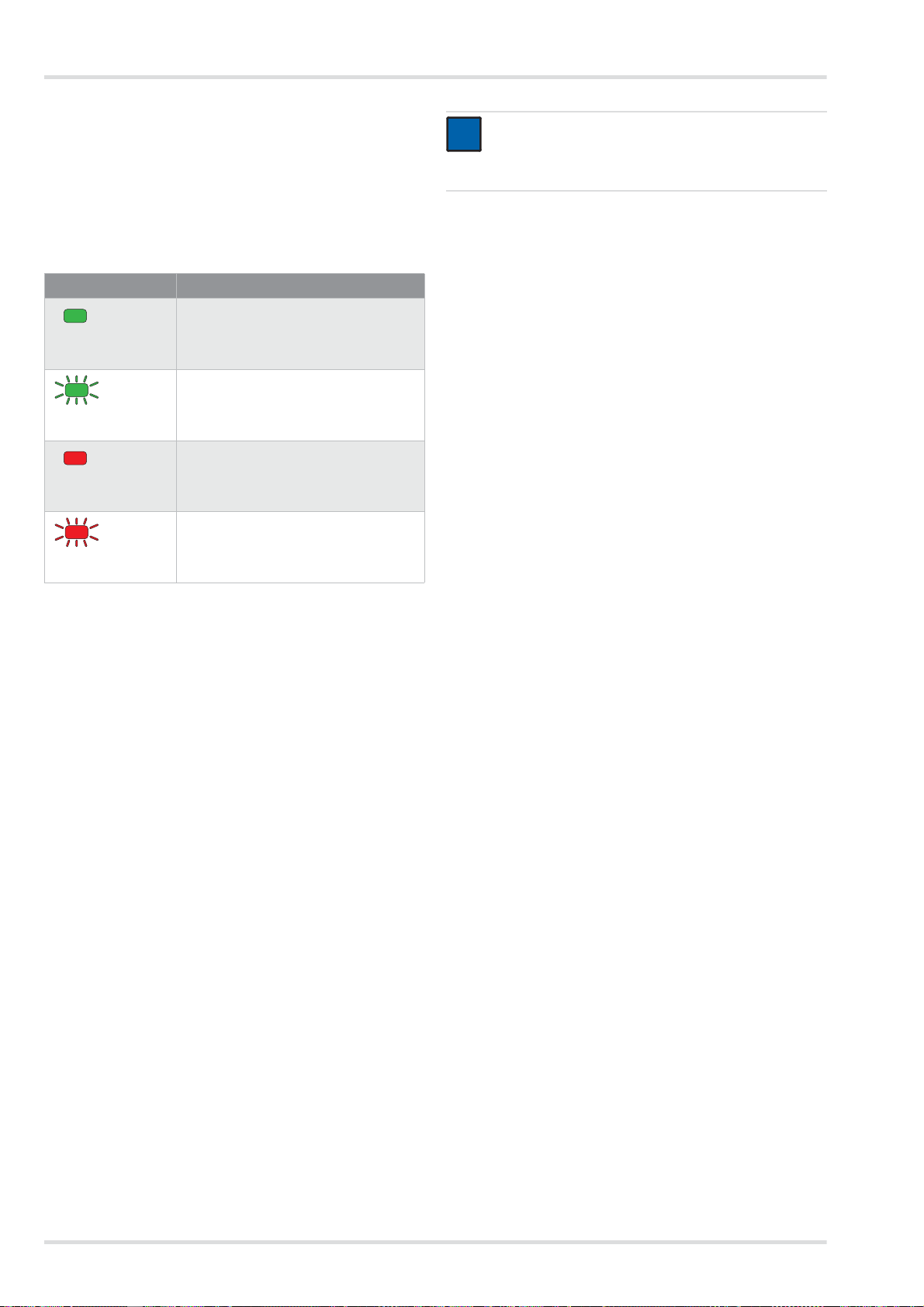
28 Dräger X-plore 8000
Description
2.2.6 Chargeurs
Chargeur standard
Ź Représentation sur la page dépliante (figure G)
1 LED de statut
2 Bloc d'alimentation
3 Logement de l'accu
Signification de la LED de statut
Lorsque l'accu est entièrement chargé, le chargeur commute
automatiquement en mode veille. En mo de ve ille, l'a ccu reste
toujours chargé complètement. Il ne passera pour autant pas
en surcharge ni ne sera endommagé.
2.3 Description du fonctionnement
Le système filtrant à ventilation assistée est un appareil de pro-
tection respiratoire dépendant de l'air environnant.
Il filtre l'air ambiant et vous met ainsi à disposition de l'air res-
pirable. Pour cela, l'appareil aspire en permanence l'air am-
biant à travers le filtre. En fonction du type de filtre, les
substances nocives sont retenues dans le filtre. De cette ma-
nière, l'air ambiant est retraité et parvient ensuite dans le rac-
cord respiratoire. Il est alors disponible comme air respiratoire.
Une surpression continue dans le raccord respiratoire agit
contre la pénétration d'air ambiant.
2.3.1 Dispositifs d'avertissement
Les défauts survenant lors de l'utilisation sont indiqués par des
dispositifs d'avertissement.
Les dispositifs d'avertissements sont entre autres les sui-
vants :
z Alarme visuelle (affichage sur le panneau de commande)
z Alarme sonore
z Alarme par vibratoire
L'unité de ventilation fournit toujours le même débit volumé-
trique préréglé.
Lorsque l'unité de ventilation ne peut plus fournir à brève
échéance le débit volumétrique préréglé (par ex. en raison
d'une saturation en hausse du filtre anti-particules), un avertis-
sement ou une alarme est émis(e).
2.4 Domaine d'utilisation
Selon le type de filtre utilisé, l'appareil offre une protection
contre les particules, les gaz, les vapeurs ou des mélanges de
ces derniers éléments.
2.5 Restrictions posées au domaine
d'utilisation
L'appareil ne convient pas pour une utilisation :
z dans les zones à explosions (zones ex)
z pour des substances nocives avec des caractéristiques
d'alerte faibles (odeur, goût, irritation des yeux et des voies
respiratoires)
z pour des interventions dans des cuves, fosses, canaux non
aérés, etc.
2.6 Autorisations
L'appareil est homologué selon :
z EN 12941:2009-02
z EN 12942:2009-02
L'appareil satisfait en conséquence à la directive relative aux
équipements de protection individuelle 89/686/CEE.
Autres directives dans le cadre du marquage CE :
z Directive CEE (2004/108/CE)
z Directive R&TTE (1999/5/CE)
z Directive NSR (2006/95/CE)
z Directive RoHS (2011/65/UE)
2.7 Explication des marquages
d'identification et des symboles
2.7.1 Plaques signalétiques
Ź Représentation des plaques signalétiques à la page 4
1 Désignation du produit
2 Type de protection
3 Normes EN satisfaites
4 Symbole "Respecter la notice d'utilisation"
5 Symbole DEEE "Collecte sélective des déchets électriques
et électroniques"
Affichage Signification
La LED de statut est
allumée en vert.
L'accu est inséré et est chargé complè-
tement (mode veille).
La LED de statut cli-
gnote en vert.
L'accu est inséré et est chargé.
La LED de statut est
allumée en rouge.
L'accu n'est pas inséré.
La LED de statut cli-
gnote en rouge.
Défaut
REMARQUE
L'alarme vibratoire est émise en plus de l'alarme so-
nore. Selon l'épaisseur et le matériau du vêtement,
l'alarme vibratoire n'est pas perceptible le cas échéant.
Unité de ventilation : Figure H
Chargeur standard : Figure I
Accu : Figure J
i
i
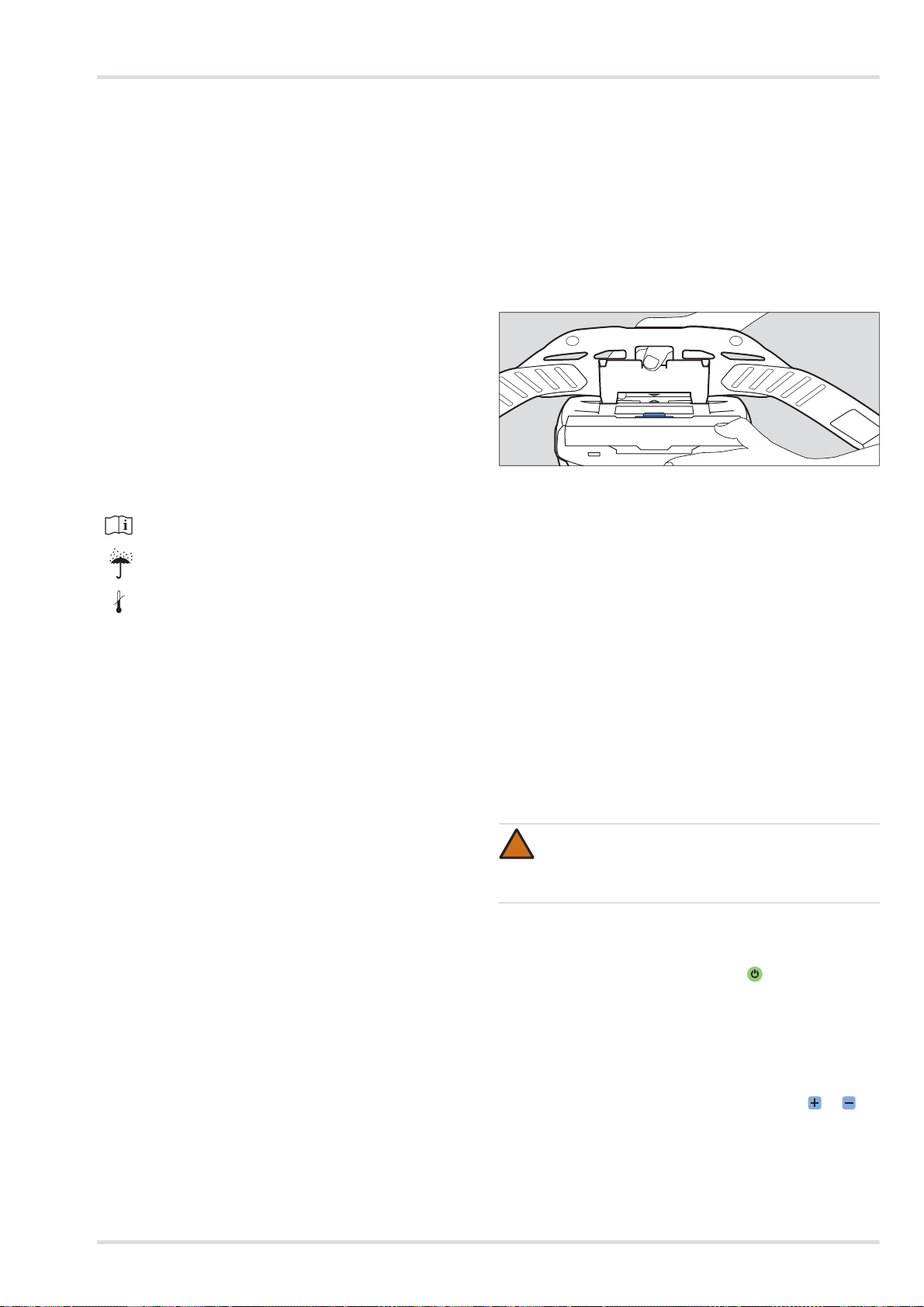
Utilisation
Dräger X-plore 8000 29
6 Pays de production
7 Fabricant
8 Marquage CE
9 Code DataMatrix avec numéro de pièce et de fabrication
10 Numéro de fabrication
11 Référence de produit
12 Utilisation uniquement en intérieur, pas en extérieur
13 Température ambiante maximale
14 Données électriques
15 Affectation des connecteurs
16 Symbole de recyclage
17 Mise en garde
Information sur l'année de fabrication
L'année de production résulte de la 3e lettre du numéro de fa-
brication : F = 2014, G = néant, H = 2015, I = néant, J = 2016,
K = 2017 etc.
Exemple : numéro de fabrication ARFH-0054 : la troisième
lettre est F, donc année de fabrication 2014.
2.7.2 Emballage
3 Utilisation
3.1 Conditions relatives à l'utilisation
z Les conditions ambiantes (en particulier le type et la
concentration des substances toxiques) doivent être
connues.
z Le taux d'oxygène dans l'air environnant ne doit pas des-
cendre en-dessous des valeurs limites suivantes :
{ au moins 17 % de volume d'oxygène dans tous les
pays européens sauf les Pays-Bas, la Belgique et la
Grande-Bretagne
{ au moins 19 % de volume d'oxygène aux Pays-Bas, en
Belgique, en Grande-Bretagne, en Australie et en Nou-
velle-Zélande
{ au moins 19,5 % de volume d'oxygène aux États-Unis.
Dans les autres pays, observer la réglementation natio-
nale.
3.2 Opérations préalables à l'utilisation
En dehors de la zone dangereuse, effectuer les activi tés sui-
vantes :
1. Sélectionner les composants du système filtrant à ventila-
tion assistée (filtre, raccord respiratoire) en fonction de la
classe de protection nécessaire et de la tâche (voir matrice
de configuration [Configuration Matrix] à la page 243).
2. Effectuer un contrôle visuel (voir le chapitre 5.3.1 à la page
32).
3. Vérifier l'état de charge de l'accu (voir le chapitre 5.3.3 à la
page 32).
4. Insérer le filtre (voir le chapitre 5.3.4 à la page 33).
5. Monter le système de port (voir le chapitre 3.2.1 à la page
29).
6. Monter éventuellement les accessoires (voir le chapitre 3.5
à la page 30).
7. Mettre en place l'appareil voir le chapitre 3.2.2 à la page
29.
8. Raccorder le raccord respiratoire (voir le chapitre 3.2.3 à la
page 29)
9. Mettre en marche l'appareil voir le chapitre 3.2.4 à la page
29.
3.2.1 Montage du système de port
1. Monter la plaque de liaison du système de port sur le loge-
ment de l'unité de ventilation. Les marquages fléchés de la
plaque de liaison et du logement doivent correspondre.
2. Appuyer sur la plaque de li aison jusqu'à ce qu'elle s'en-
clenche de manière audible sur le logement.
3.2.2 Mise en place de l'appareil
1. Régler le ceinturon du système de port à la taille néces-
saire.
2. Retourner le ce inturon et fermer la boucle. L'appareil se
trouve sur le dos de l'utilisateur.
3. Tendre le ceinturon et fixer les extrémités qui dépassent
avec les attaches du ceinturon.
3.2.3 Raccordement du raccord respiratoire
1. Raccorder le raccord à encliqueter du tuyau respiratoire
sur l'unité de ventilation.
2. Relier l'autre extrémité du tuyau respiratoire au raccord
respiratoire.
3.2.4 Mise en marche de l'appareil
1. Mettre en marche l'unité de ventil ation en appuyant (pen-
dant 2 secondes env.) sur la touche sur le panneau de
commande.
L'appareil effectue un autotest après la mise en marche.
2. Lorsque l'appareil ne foncti onne pas parfaitement ou que
des dispositifs d'avertissement se déclenchent, éliminer le
défaut (voir le chapitre 4 à la page 30).
3. Monter le raccord respiratoire (voir la notice d'utilisation du
raccord respiratoire correspondant).
4. Ajuster le débit volumétrique avec les touches et se-
lon vos souhaits.
Observer la notice d'utilisation
Humidité maximale de stockage
Plage de la température de stockage
<95%
-20°C
+70°C
AVERTISSEMENT
Entrée d'air ambiant !
Avant utilisation, s'assurer que tous les composants
sont bien attachés les uns aux autres.
04733412.eps
!
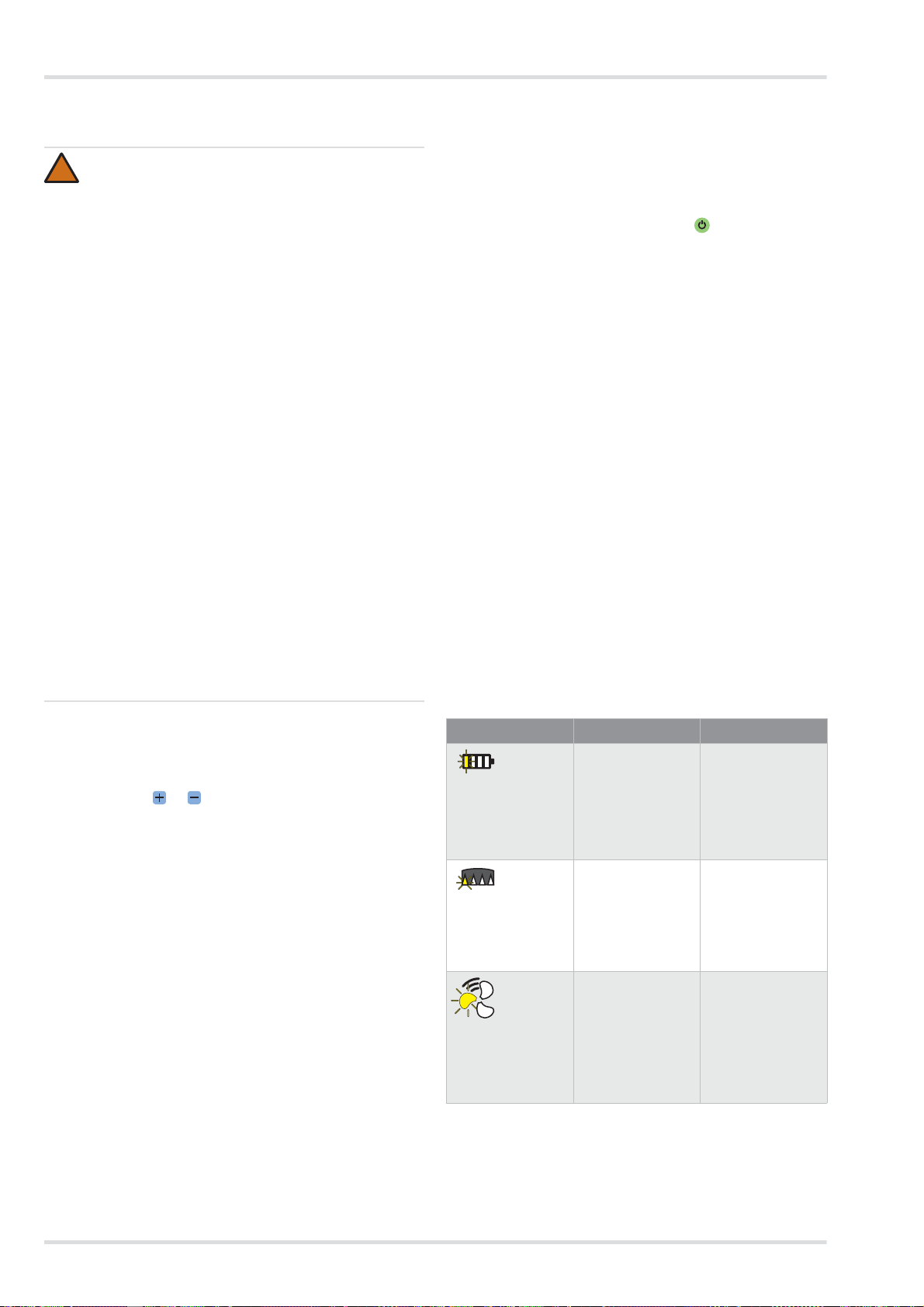
30 Dräger X-plore 8000
Élimination des pannes
3.3 Pendant l'utilisation
3.3.1 Régulation a posteriori du débit volumétrique
Si nécessaire (par ex. en cas d'effort corporel accru), réguler à
postériori le débit volumétrique pendant le fonctionnement
avec les touches et .
3.3.2 Avertissements et alarmes
Si une alerte est déclenchée, quitter sans délai la zone de tra-
vail compte tenu de la situation dangereuse possible.
Afin d'augmenter la durée d'utilisation lorsqu'une alerte sur-
vient, diminuer le débit volumétrique. (Uniquement possible
lorsque le niveau le plus faible n'est pas déjà sélectionné.) En
baissant le débit volumétrique, la durée de fonctionnement de
l'accu peut par ex. être prolongée.
Si une alarme est déclenchée, quitter la zone de travail immé-
diatement, sans délai.
Après déclenchement d'une alarme ou d'un avertissement, vé-
rifier le fonctionnement de l'appareil (voir le chapitre 4 à la
page 30).
3.4 Après l'utilisation
Effectuer les activités suivantes :
1. Quitter la zone dangereuse.
2. Déposer le raccord respiratoire (voir la n otice d'utilisation
du raccord respiratoire correspondant).
3. Mettre l'unité de ventilation hors service en appuyant (pen-
dant 2 secondes env.) sur la touche sur le panneau de
commande.
4. Ouvrir le ceinturon du système de port et retirer l'appareil.
5. Nettoyage et désinfection de l'appareil (voir le chapitre 5.2
à la page 32)
3.5 Opérations générales réservées à
l'utilisateur
3.5.1 Pose de la mousse de confort pour un ceinturon
standard
Relier la mousse de confort au ceinturon standard avec les
boutons à pression.
3.5.2 Montage de la rallonge du ceinturon le système de
port
Si nécessaire, monter la rallonge de ceinture sur la boucle d e
la sangle.
4 Élimination des pannes
4.1 Avertissements
Le type d'avertissement est signalé de manière visuelle par un
clignotement jaune de l'affichage correspondant. De plus, un
signal d'avertissement sonore est déclenché et l'alarme vibra-
toire se déclenche.
AVERTISSEMENT
Danger pour la santé !
Quitter immédiatement la zone dangereuse dans les
cas suivants :
z Alimentation d'air en baisse ou interrompue
(par ex. en raison d'une panne du ventilateur)
Avec le type de raccord respiratoire cagoule/
casque/visière de protection, une accumulation de
dioxyde de carbone ou un manque d'oxygène peut
vite survenir. En outre, un air ambiant nocif peut
pénétrer dans la cagoule.
z Développement d'odeur ou du goût dans le raccord
respiratoire (passage à travers le filtre). La capaci-
té restante du filtre à gaz ou des composants du
filtre à gaz du filtre combiné est épuisée.
z Torpeur, vertige ou autres douleurs
z Endommagement de l'appareil
z Autres alarmes affichées (voir le chapitre 4 à la
page 30)
Les tuyaux respiratoires ou autres composants
masquent le risque d'accrochage. Cela peut amener
un endommagement de l'appareil et une interruption
de l'alimentation en air !
Lors de l'utilisation de l'appareil, procéder avec pré-
caution.
Lors de l'utilisation du type de raccord respiratoire ca-
goule/casque/visière de protection, une dépression
peut survenir lors de l'inspiration en cas de travail diffi-
cile et de l'air non filtré peut pénétrer !
Afin de contrer ce phénomène, augmenter le débit vo-
lumétrique.
!
Erreur Cause Solution
Un segment de
l'affichage de l'état
de charge de l'ac-
cu clignote en
jaune.
La durée de fonc-
tionnement res-
tante de l'accu est
faible
(< 30 minutes).
Charger rapide-
ment l'accu ou le
remplacer par un
accu entièrement
chargé (voir le cha-
pitre 5.3.3 à la
page 32).
Un segment de
l'affichage de la ca-
pacité restante du
filtre à particules
clignote en jaune.
La capacité res-
tante du filtre à par-
ticules est faible
(< 20 %).
Remplacer rapide-
ment le filtre à par-
ticules ou le filtre
combiné (voir le
chapitre 5.3.4 à la
page 33).
Un segment de
l'affichage du débit
volumétrique cli-
gnote en jaune.
Défaut lors de la
mise en marche
(par ex. en raison
d'un tuyau ou filtre
manquant).
Vérifier le fonction-
nement de l'appa-
reil et préparer
l'appareil de nou-
veau pour l'utilisa-
tion (voir le
chapitre 3.2 à la
page 29).
 Loading...