

Page 1
Gebrauchsanweisung
de
5
Instructions for Use
en
15
Notice d’utilisation
fr
25
Instrucciones de uso
es
36
Instruções de utilização
pt
47
Istruzioni per l'uso
it
58
Gebruiksaanwijzing
nl
69
Brugsanvisning
da
80
Käyttöohjeet
fi
90
Bruksanvisning
no
100
Bruksanvisning
sv
110
Instrukcja obsáugi
pl
121
Ɋɭɤɨɜɨɞɫɬɜɨ ɩɨ ɡɤɫɩɥɭɚɬɚɰɢɢ
ru
132
Upute za uporabu
hr
144
Navodilo za uporabo
sl
155
Návod na použitie
sk
166
Návod na použití
cs
177
Ɋɴɤɨɜɨɞɫɬɜɨ ɡɚ ɪɚɛɨɬ
bg
188
InstrucĠiuni de utilizare
ro
200
Használati útmutató
hu
211
Kullanma talimatlarÕ
tr
222
∎䞷広㢝
zh
233
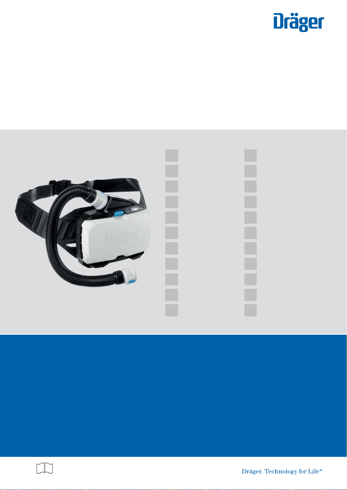
Dräger X-plore® 8000
Page 2

Page 3
1
4
2
3
B
5
6
3
21
4
C
0158
IP 65
EN 12941
EN 12942
CAXXX (Brasilien)
Contains FCC ID: T7VPAN10
Contains IC: 216Q-PAN10
Dräger Safety AG & Co. KGaA, 23560 Lübeck, Germany Made in Germany
X-plore 8500 (IP)
Part-No. : R59XXX
Serial-No. : AREE-0001
2
5
1
43
4
1
2 3
F
334
2
1
E
D
1
2
6
5
34
00133412.eps
3
2
1
G
A
Page 4
00233412.eps
J
X-plore 8000 Standard Charger
IP 30
T50
Input: 15 V / 4 A
Output: 9 - 12,6 V / 4 A
Dräger Safety AG & Co. KGaA, 23560 Lübeck, Germany Made in China
X
Part-No. : R59580
Serial-No. : AREE-0001
1 92
4
12
7
67 15 13
9
10
11
14
X
0158
IP 65
EN 12941
EN 12942
Dräger Safety AG & Co. KGaA, 23560 Lübeck, Germany Made in Germany
X-plore 8000
Standard Battery
Part-No. : R59565
Serial-No. : AREE-0001
Rechargeable Li-Ion Battery 10,8 V; 3,35 Ah; 36 Wh
Must be recycled or disposed of properly
Caution: Charge with dedicated charger only
May explode if damaged or disposed of in fire
Do not short circuit
1 17
9
10
11
8
23
6
4
5
16
7
I
H
X
0158
IP 65
EN 12941
EN 12942
Dräger Safety AG & Co. KGaA, 23560 Lübeck, Germany Made in Germany
X-plore 8500 (IP)
Part-No. : R59500
Serial-No. : AREE-0001
123
4
5
67
8
9
10
11
4 Dräger X-plore 8000
Page 5

Inhalt
Inhalt
1 Zu Ihrer Sicherheit . . . . . . . . . . . . . . . . . . . . . . . . .6
1.1 Allgemeine Sicherheitshinweise . . . . . . . . . . . . . . . .6
1.2 Bedeutung der Warnzeichen . . . . . . . . . . . . . . . . . .6
2 Beschreibung . . . . . . . . . . . . . . . . . . . . . . . . . . . . .6
2.1 Systemübersicht . . . . . . . . . . . . . . . . . . . . . . . . . . . .6
2.2 Komponenten . . . . . . . . . . . . . . . . . . . . . . . . . . . . . .6
2.2.1 Gebläseeinheit . . . . . . . . . . . . . . . . . . . . . . . . . . . . .6
2.2.2 Filter und Atemanschlüsse . . . . . . . . . . . . . . . . . . . .7
2.2.3 Atemschläuche . . . . . . . . . . . . . . . . . . . . . . . . . . . . .7
2.2.4 Tragesysteme . . . . . . . . . . . . . . . . . . . . . . . . . . . . . .7
2.2.5 Akkus . . . . . . . . . . . . . . . . . . . . . . . . . . . . . . . . . . . .7
2.2.6 Ladegeräte . . . . . . . . . . . . . . . . . . . . . . . . . . . . . . . .7
2.3 Funktionsbeschreibung . . . . . . . . . . . . . . . . . . . . . . .8
2.3.1 Warneinrichtungen . . . . . . . . . . . . . . . . . . . . . . . . . .8
2.4 Verwendungszweck . . . . . . . . . . . . . . . . . . . . . . . . .8
2.5 Einschränkungen des Verwendungszwecks . . . . . . .8
2.6 Zulassungen . . . . . . . . . . . . . . . . . . . . . . . . . . . . . . .8
2.7 Symbolerklärung und typidentische Kennzeichnung 8
2.7.1 Typenschilder . . . . . . . . . . . . . . . . . . . . . . . . . . . . . .8
2.7.2 Verpackung . . . . . . . . . . . . . . . . . . . . . . . . . . . . . . . .9
3 Gebrauch . . . . . . . . . . . . . . . . . . . . . . . . . . . . . . . . .9
3.1 Voraussetzungen für den Gebrauch . . . . . . . . . . . . .9
3.2 Vorbereitungen für den Gebrauch . . . . . . . . . . . . . .9
3.2.1 Tragesystem montieren . . . . . . . . . . . . . . . . . . . . . .9
3.2.2 Gerät anlegen . . . . . . . . . . . . . . . . . . . . . . . . . . . . . .9
3.2.3 Atemanschluss anschließen . . . . . . . . . . . . . . . . . . .9
3.2.4 Gerät einschalten . . . . . . . . . . . . . . . . . . . . . . . . . . .9
3.3 Während des Gebrauchs . . . . . . . . . . . . . . . . . . . .10
3.3.1 Volumenstrom nachregulieren . . . . . . . . . . . . . . . .10
3.3.2 Warnungen und Alarme . . . . . . . . . . . . . . . . . . . . .10
3.4 Nach dem Gebrauch . . . . . . . . . . . . . . . . . . . . . . . .10
3.5 Allgemeine Benutzeraufgaben . . . . . . . . . . . . . . . .10
3.5.1 Komfortpolster für Standardgürtel anbringen . . . . .10
3.5.2 Gurtverlängerung am Tragesystem anbringen . . . .10
4 Störungsbeseitigung . . . . . . . . . . . . . . . . . . . . . .10
4.1 Warnungen . . . . . . . . . . . . . . . . . . . . . . . . . . . . . . .10
4.2 Alarme . . . . . . . . . . . . . . . . . . . . . . . . . . . . . . . . . . .11
5 Wartung . . . . . . . . . . . . . . . . . . . . . . . . . . . . . . . . .11
5.1 Instandhaltungsintervalle . . . . . . . . . . . . . . . . . . . .11
5.2 Reinigung und Desinfektion . . . . . . . . . . . . . . . . . .11
5.2.1 Gerät reinigen und desinfizieren . . . . . . . . . . . . . . .11
5.3 Wartungsarbeiten . . . . . . . . . . . . . . . . . . . . . . . . . .11
5.3.1 Sichtprüfung durchführen . . . . . . . . . . . . . . . . . . . .11
5.3.2 Ladezustand des Akkus prüfen . . . . . . . . . . . . . . . .12
5.3.3 Akku wechseln oder laden . . . . . . . . . . . . . . . . . . .12
5.3.4 Filter wechseln . . . . . . . . . . . . . . . . . . . . . . . . . . . .12
5.3.5 Volumenstrom und Warneinrichtungen prüfen . . . .12
5.3.6 O-Ring am Steck- oder Bajonettanschluss der
Schläuche wechseln . . . . . . . . . . . . . . . . . . . . . . . .13
6 Transport . . . . . . . . . . . . . . . . . . . . . . . . . . . . . . . .13
7 Lagerung . . . . . . . . . . . . . . . . . . . . . . . . . . . . . . . .13
8 Entsorgung . . . . . . . . . . . . . . . . . . . . . . . . . . . . . 13
9 Technische Daten . . . . . . . . . . . . . . . . . . . . . . . . 13
10 Bestellliste . . . . . . . . . . . . . . . . . . . . . . . . . . . . . . 14
Dräger X-plore® 8000 5
Page 6
Zu Ihrer Sicherheit
!
!
i
i
1 Zu Ihrer Sicherheit
1.1 Allgemeine Sicherheitshinweise
z Vor Gebrauch des Produkts diese Gebrauchsanweisung
und die der zugehörigen Komponenten aufmerksam lesen.
z Gebrauchsanweisung genau beachten. Der Anwender
muss die Anweisungen vollständig verstehen und den
Anweisungen genau Folge leisten. Das Produkt darf nur
entsprechend dem Verwendungszweck verwendet
werden.
z Gebrauchsanweisung nicht entsorgen. Aufbewahrung und
ordnungsgemäße Verwendung durch die Nutzer
sicherstellen.
z Nur geschultes und fachkundiges Personal darf dieses
Produkt verwenden.
z Lokale und nationale Richtlinien, die dieses Produkt
betreffen, befolgen.
z Nur geschultes und fachkundiges Personal darf das
Produkt überprüfen, reparieren und instand halten.
z Nur Original-Dräger-Teile und -Zubehör verwenden. Sonst
könnte die korrekte Funktion des Produkts beeinträchtigt
werden.
z Fehlerhafte oder unvollständige Produkte nicht
verwenden. Keine Änderungen am Produkt vornehmen.
z Dräger bei Fehlern oder Ausfällen vom Produkt oder von
Produktteilen informieren.
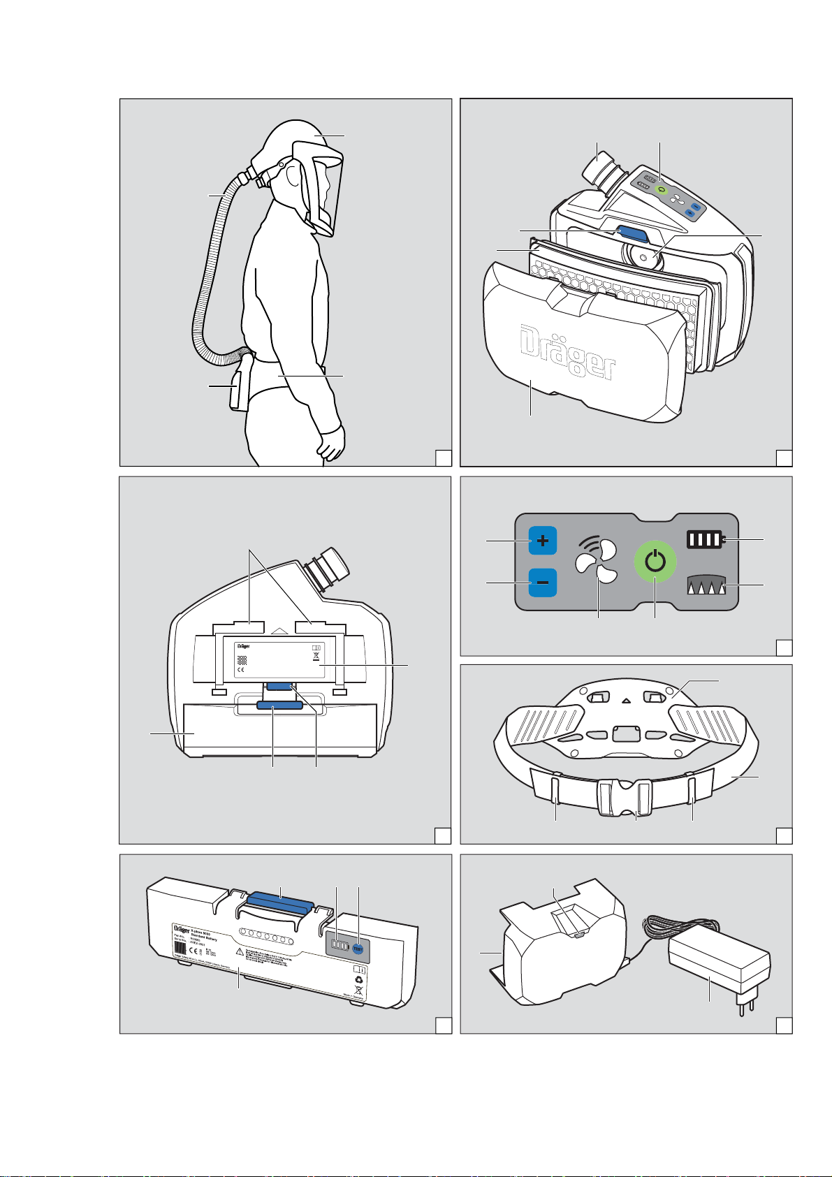
Ź Darstellung der Systemübersicht auf der Ausklappseite
(Abbildung A)
Zu einem vollständigen Gerät gehören:
1 Atemschlauch
2 Atemanschluss (Beispiel mit Helm)
3 Tragesystem
4 Gebläseeinheit mit Filter und Akku
Ggf. Zubehörkomponenten (ohne Abbildung)
HINWEIS
i
i
Für eine Übersicht der Gerätekombinationen und der
entsprechenden Schutzklasse siehe Konfigurationsmatrix (Configuration Matrix) auf Seite 243.
Die Zahlen in der oberen Zeile der Konfigurationsmatrix entsprechen den Positionen in der Bestellliste.
Die gelisteten Komponenten sind hierbei für die Verwendung mit der X-plore 8500 Gebläseeinheit (Bestellliste Pos. 1) und den Akkus (Pos. 2 und 3)
bestimmt.
Bei Fragen zur Konfiguration des Geräts Dräger kontaktieren.
2.2 Komponenten
1.2 Bedeutung der Warnzeichen
Die folgenden Warnzeichen werden in diesem Dokument verwendet, um die zugehörigen Warntexte zu kennzeichnen und
hervorzuheben, die eine erhöhte Aufmerksamkeit seitens des
Anwenders erfordern. Die Bedeutungen der Warnzeichen sind
wie folgt definiert:
WARNUNG
Hinweis auf eine potenzielle Gefahrensituation.
Wenn diese nicht vermieden wird, können Tod oder
schwere Verletzungen eintreten.
VORSICHT
Hinweis auf eine potenzielle Gefahrensituation. Wenn
diese nicht vermieden wird, können Verletzungen oder
Schädigungen am Produkt oder der Umwelt eintreten.
Kann auch als Warnung vor unsachgemäßem Gebrauch verwendet werden.
HINWEIS
Zusätzliche Information zum Einsatz des Produkts.
2 Beschreibung
2.1 Systemübersicht
Das Gebläsefiltergerät Dräger X-plore®80001) kann je nach
Einsatzbereich und erforderlicher Schutzklasse aus unterschiedlichen Komponenten zusammengesetzt werden. Hierbei insbesondere die Einsatzgrenzen der Filter beachten
(siehe Gebrauchsanweisung der Filter).
2.2.1 Gebläseeinheit
Die Gebläseeinheit ist die zentrale Komponente des Geräts.
Gerätemerkmale:
z Bedienfeld mit Anzeige des aktuellen Systemzustands
z Elektronische Überwachung der Gerätefunktionen
{ Volumenstrom
{ Restkapazität des Partikelfilters
{ Ladezustand des Akkus
{ Erkennung vom Gerät getrennter Schläuche oder Filter
z Automatische Erkennung des verwendeten Ateman-
schlusstyps (Halb-/Vollmaske oder Haube/Helm/Schutzvisier) und entsprechende Anpassung des
Volumenstrombereichs
z Dreistufig wählbarer Volumenstrom
z Optische Erkennung des Filtertyps über Farbkennzeich-
nung (Farbpunkt am Filter)
Ź Darstellung der Vorderseite der Gebläseeinheit auf der
Ausklappseite (Abbildung B)
1 Schlauchanschluss
2 Bedienfeld
3 Ansaugöffnung
4 Spritzschutzdeckel
5 Filter (nicht im Lieferumfang der Gebläseeinheit)
6 Filterverriegelungstaste
1) X-plore® ist eine eingetragene Marke von Dräger.
6 Dräger X-plore 8000
Page 7

Beschreibung
i
i
Ź Darstellung der Rückseite der Gebläseeinheit auf der Aus-
klappseite (Abbildung C)
1 Tragesystemaufnahme
2 Typenschild
3 Tragesystem-Verriegelungstaste
4 Akkuverriegelungstaste
5 Akku (nicht im Lieferumfang der Gebläseeinheit)
Bedienfeld
Ź Darstellung auf der Ausklappseite (Abbildung D)
1 Ladezustandsanzeige des Akkus
2 Restkapazitätsanzeige des Partikelfilters
3 Ein/Aus-Taste
4 Volumenstromanzeige
5 Volumenstrom senken
6 Volumenstrom erhöhen
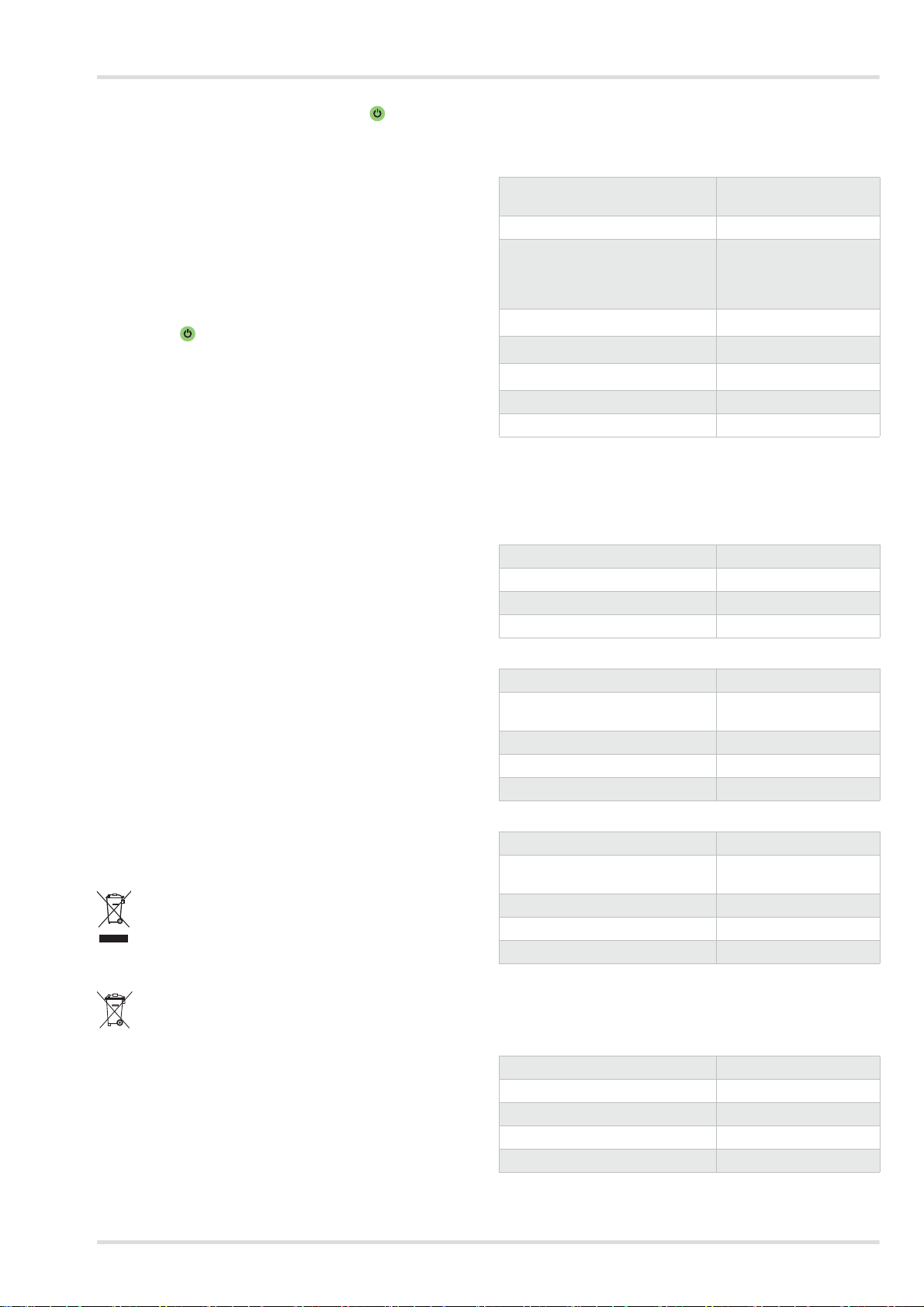
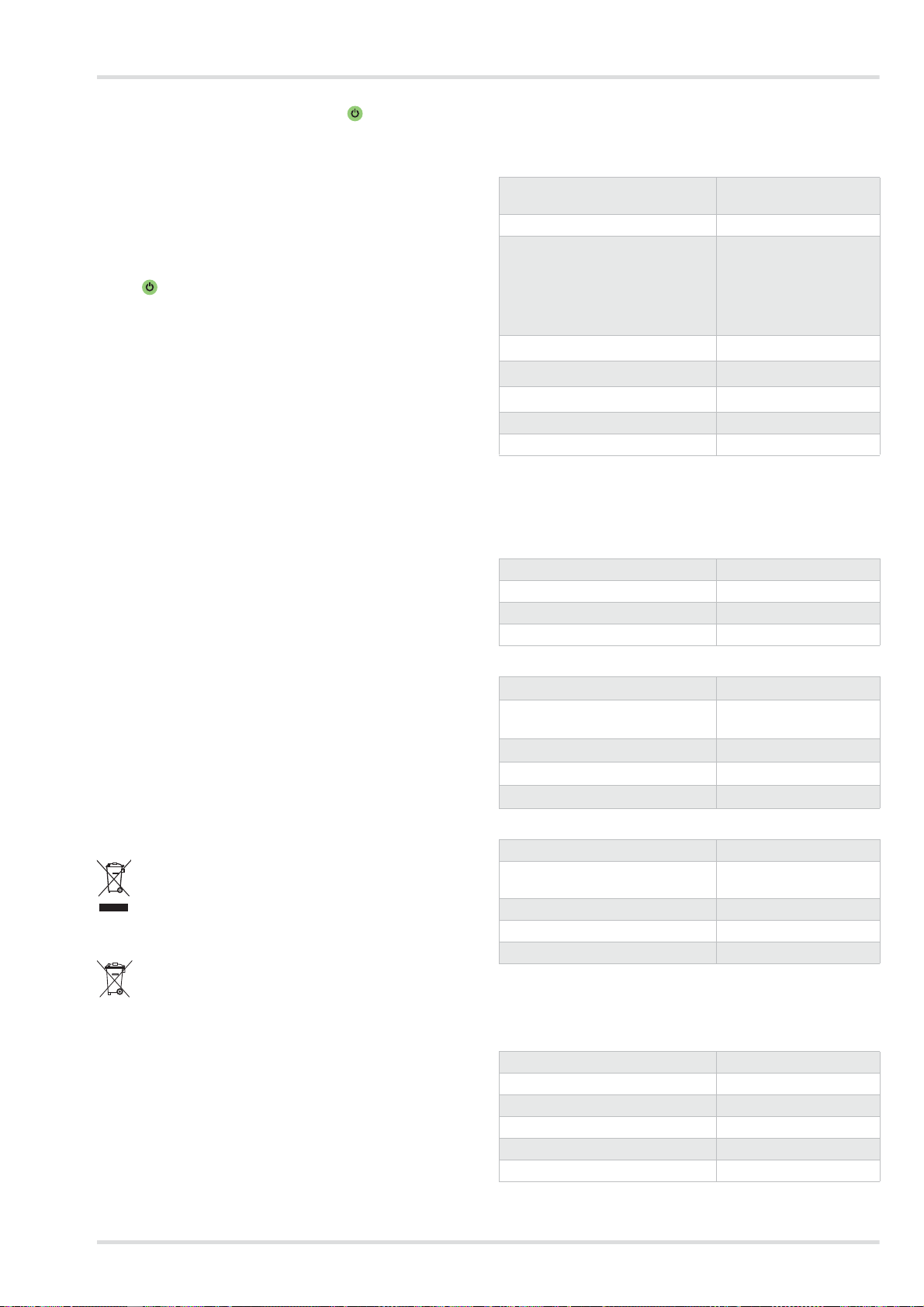
Bedeutung der Anzeigen auf dem Bedienfeld
Anzeige Bedeutung
Ladezustand je nach Anzahl der angezeigten Segmente:
Segmente leuchten
grün.
> 75 % (4 Segmente)
> 50 % (3 Segmente)
> 25 % (2 Segmente)
< 25 % (1 Segment)
Restkapazität des Partikelfilters 1) je
nach Anzahl der angezeigten Segmen-
Segmente leuchten
te:
grün.
> 75 % (4 Segmente)
> 50 % (3 Segmente)
> 25 % (2 Segmente)
< 25 % (1 Segment)
Stärke des Volumenstroms je nach Anzahl der angezeigten Segmente:
Segmente leuchten
grün.
1) Die Restkapazität des Gasfilters oder der Gasfilterkomponenten
des Kombinationsfilters kann nicht angezeigt werden.
Hoher Volumenstrom (3 Segmente)
Mittlerer Volumenstrom (2 Segmente)
Niedriger Volumenstrom (1 Segment)
HINWEIS
Warnungen oder Alarme werden durch gelb oder rot
blinkende LEDs angezeigt. Zur Bedeutung der Anzeigen bei Störungen siehe Kapitel 4 auf Seite 10.
2.2.2 Filter und Atemanschlüsse
Filter und Atemanschlüsse sind in separaten Gebrauchsanweisungen beschrieben.
2.2.3 Atemschläuche
Folgende Atemschläuche stehen zur Verfügung:
z Standardschlauch
z Flexibler Schlauch für erhöhten Komfort
z Steckanschluss (Haube)
z Bajonettanschluss (Helm und Schutzvisier)
z Rundgewindeanschluss (Halb-/Vollmaske)
2.2.4 Tragesysteme
Ź Darstellung auf der Ausklappseite (Abbildung E)
1 Verbindungsplatte
2 Gurtband
3 Gurtendenklammern
4 Schnalle
Folgende Tragesysteme sind verfügbar:
z Standardgürtel
Der Standardgürtel verfügt über ein textiles Gurtband und
Druckknöpfe zum Befestigen eines optionalen Komfortpolsters.
z Dekontaminierbarer Gürtel:
Der dekontaminierbare Gürtel verfügt über ein glattes
Kunststoff-Gurtband und ist speziell zum Dekontaminieren
geeignet.
2.2.5 Akkus
Ź Darstellung auf der Ausklappseite (Abbildung F)
1 Akkuverriegelungstaste
2 Ladezustandsanzeige
3 Taste zum Anzeigen des Ladezustands
4 Typenschild
Die Li-Ionen-Akkus sind speziell für den Einsatz mit dem Gebläsefiltergerät ausgerüstet. Neben dem Standardakku ist
noch ein Langzeitakku mit höherer Betriebsdauer erhältlich.
Die Ladezustandsanzeige zeigt den Ladezustand während
des Ladens mit dem Standardladegerät oder beim Betätigen
der Taste. Während des Ladens blinken die Segmente der Ladezustandsanzeige.
Die Ladezustandsanzeige entspricht der auf dem Bedienfeld
der Gebläseeinheit (siehe Kapitel 2.2.1 auf Seite 6).
Die Akkus erreichen erst nach 5 Lade- und Entladezyklen ihre
volle Kapazität. Die normale Ladezeit beträgt ca. 3 Stunden.
Bei starker Entladung wird der Akku vorgeladen, wodurch sich
die Ladezeit um bis zu 4 Stunden verlängern kann. In dieser
Zeit wird die Ladezustandsanzeige nicht unterstützt.
Um Beschädigung oder Explosion des Akkus auszuschließen,
erfolgt der Ladevorgang nur im Temperaturbereich von 0 bis
50 °C. Beim Verlassen des Temperaturbereichs wird der Ladevorgang automatisch unterbrochen und nach Rückkehr in den
Temperaturbereich fortgesetzt.
2.2.6 Ladegeräte
Standardladegerät
Ź Darstellung auf der Ausklappseite (Abbildung G)
1 Status-LED
2 Netzteil
3 Akkuaufnahme
Beide Atemschläuche sind jeweils für folgende Atemanschlusstypen erhältlich:
Dräger X-plore 8000 7
Page 8
Beschreibung
i
i
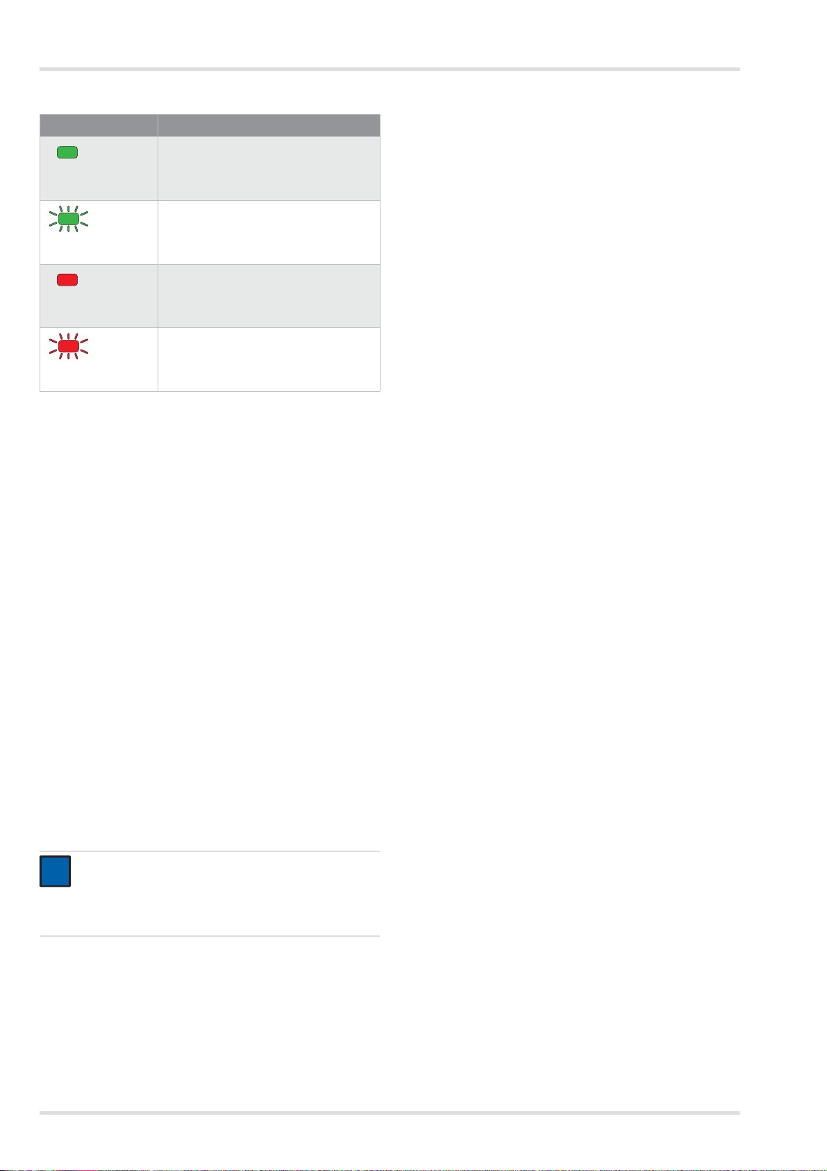
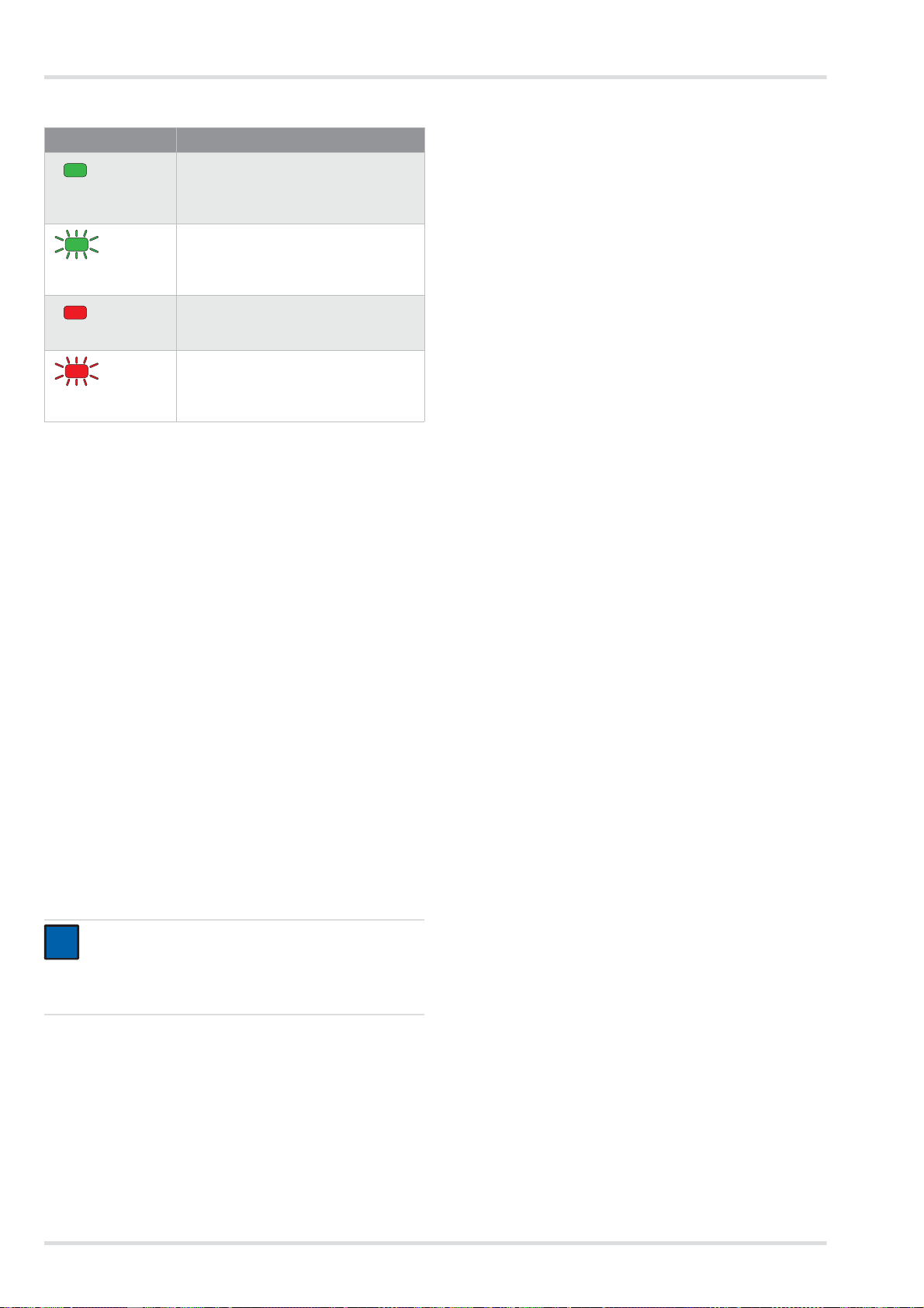
Bedeutung der Status-LED
Anzeige Bedeutung
Akku ist eingelegt und ist vollständig
geladen (Standby-Betrieb)
Status-LED leuchtet
grün.
Akku ist eingelegt und wird geladen.
Status-LED blinkt
grün.
Akku ist nicht eingelegt.
Status-LED leuchtet
rot.
Störung
Status-LED blinkt
rot.
Wenn der Akku vollständig geladen ist, schaltet das Ladegerät
automatisch in den Standby-Betrieb. Im Standby-Betrieb bleibt
der Akku immer vollständig aufgeladen. Hierbei wird der Akku
weder überladen noch beschädigt.
2.3 Funktionsbeschreibung
Das Gebläsefiltergerät ist ein umluftabhängiges Atemschutzgerät.
2.4 Verwendungszweck
Je nach verwendetem Filtertyp schützt das Gerät vor Partikeln, Gasen und Dämpfen oder Kombinationen hieraus.
2.5 Einschränkungen des
Verwendungszwecks
Das Gerät ist nicht geeignet für die Verwendung:
z in explosionsgefährdeten Bereichen (Ex-Bereichen)
z bei Schadstoffen mit geringen Warneigenschaften (Ge-
ruch, Geschmack, Reizung der Augen und Atemwege)
z für Einsätze in unbelüfteten Behältern, Gruben, Kanälen
usw.
2.6 Zulassungen
Das Gerät ist zugelassen nach
z EN 12941:2009-02
z EN 12942:2009-02
Das Gerät erfüllt damit die Richtlinie über persönliche Schutzausrüstung 89/686/EWG.
Weitere Richtlinien im Rahmen der CE-Kennzeichnung:
z EMV-Richtlinie (2004/108/EG)
z R&TTE-Richtlinie (1999/5/EG)
z NSR-Richtlinie (2006/95/EG)
z RoHS-Richtlinie (2011/65/EU)
Es filtert Umgebungsluft und stellt sie als Atemluft zur Verfügung. Hierzu saugt das Gerät permanent Umgebungsluft
durch das Filter an. Im Filter werden dem Filtertyp entsprechend schädliche Stoffe gebunden. Auf diese Weise wird die
Umgebungsluft aufbereitet und gelangt schließlich in den Atemanschluss. Dort steht sie als Atemluft bereit.
Ein kontinuierlicher Überdruck im Atemanschluss wirkt dem
Eindringen von Umgebungsluft entgegen.
2.3.1 Warneinrichtungen
Während des Gebrauchs auftretende Störungen werden durch
Warneinrichtungen angezeigt.
Zu den Warneinrichtungen gehören:
z Optischer Alarm (Anzeige am Bedienfeld)
z Akustischer Alarm
z Vibrationsalarm
HINWEIS
Der Vibrationsalarm wird zusätzlich zum akustischen
Alarm ausgegeben. Je nach Dicke und Material der
Kleidung ist der Vibrationsalarm ggf. nicht wahrnehmbar.
Die Gebläseeinheit liefert immer den selben voreingestellten
Volumenstrom.
Wenn die Gebläseeinheit den voreingestellten Volumenstrom
in absehbarer Zeit nicht mehr halten kann (z. B. durch zunehmende Sättigung des Partikelfilters), wird eine Warnung oder
ein Alarm ausgegeben.
2.7 Symbolerklärung und typidentische
Kennzeichnung
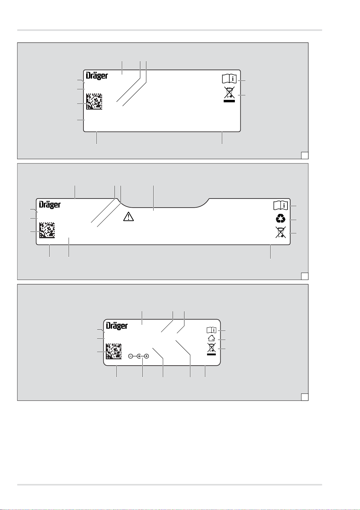
2.7.1 Typenschilder
Ź Darstellung der Typenschilder auf Seite 4
Gebläseeinheit: Abbildung H
Standardladegerät: Abbildung I
Akku: Abbildung J
1 Produktbezeichnung
2 Schutzart
3 Erfüllte EN-Normen
4 Symbol “Gebrauchsanweisung beach ten”
5 WEEE-Symbol “getrennte Sammlung von Elektro- und
Elektronikgeräten”
6 Produktionsland
7 Hersteller
8 CE-Kennzeichnung
9 DataMatrix-Code mit Teile- und Fabrikationsnummer
10 Fabrikationsnummer
11 Sachnummer
12 Verwendung nur im Haus, nicht im Freien
13 Maximale Umgebungstemperatur
14 Elektrische Daten
15 Steckerbelegung
16 Recycling-Symbol
17 Warnkennzeichnung
8 Dräger X-plore 8000
Page 9
Gebrauch
<95%
-20°C
+70°C
04733412.eps
!
Information zum Baujahr
Das Baujahr ergibt sich aus dem 3. Buchstaben der Fabrikati-
onsnummer: F = 2014, G = entfällt, H = 2015, I = entfällt, J =
2016, K = 2017 usw.
Beispiel: Fabrikationsnummer ARFH-0054: Der dritte Buchstabe ist F, also Baujahr 2014.
2.7.2 Verpackung
Gebrauchsanweisung beachten
Maximale Lagerluftfeuchte
Bereich der Lagertemperatur
3 Gebrauch
3.1 Voraussetzungen für den Gebrauch
z Die Umgebungsverhältnisse (insbesondere Art und Kon-
zentration der Schadstoffe) müssen bekannt sein.
z Der Sauerstoffgehalt der Umgebungsluft darf nicht unter
folgende Grenzwerte sinken:
{ Mindestens 17 Vol.-% Sauerstoff in allen europäischen
Ländern außer den Niederlanden, Belgien und Großbritannien
{ Mindestens 19 Vol.-% Sauerstoff in den Niederlanden,
Belgien, Großbritannien, Australien und Neuseeland
{ Mindestens 19,5 Vol.-% Sauerstoff in den USA
In anderen Ländern nationale Richtlinien beachten.
3.2 Vorbereitungen für den Gebrauch
Außerhalb des Gefahrenbereichs folgende Tätigkeiten durchführen:
1. Komponenten des Gebläsefiltergeräts (Filter, Atemanschluss usw.) entsprechend der erforderlichen Schutzklasse und der Arbeitsaufgabe auswählen (siehe
Konfigurationsmatrix [Configuration Matrix] auf Seite 243).
2. Sichtprüfung durchführen (siehe Kapitel 5.3.1 auf Seite
11).
3. Ladezustand des Akkus prüfen (siehe Kapitel 5.3.3 auf
Seite 12).
4. Filter einsetzen (siehe Kapitel 5.3.4 auf Seite 12).
5. Tragesystem montieren (siehe Kapitel 3.2.1 auf Seite 9).
6. Ggf. Zubehörteile anbringen (siehe Kapitel 3.5 auf Seite
10).
7. Gerät anlegen (siehe Kapitel 3.2.2 auf Seite 9).
8. Atemanschluss anschließen (siehe Kapitel 3.2.3 auf Seite
9)
9. Gerät einschalten (siehe Kapitel 3.2.4 auf Seite 9).
3.2.1 Tragesystem montieren
1. V erbindungsplatte des Tragesystems an der Aufnahme der
Gebläseeinheit ansetzen. Die Pfeilmarkierungen der Verbindungsplatte und der Aufnahme müssen übereinstimmen.
2. V erbindungsplatte herunterdrücken, bis sie an der Aufnahme hörbar einrastet.
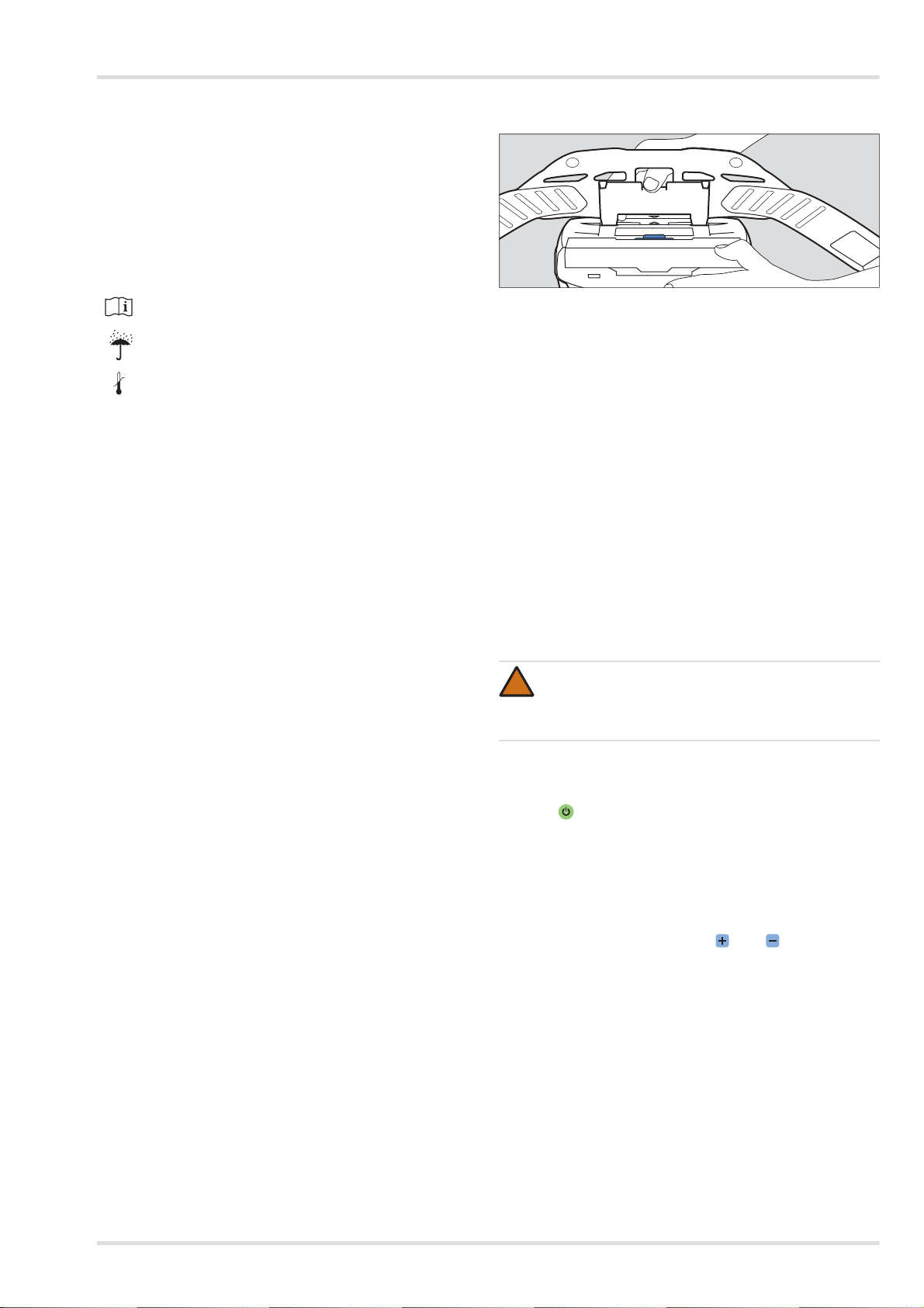
3.2.2 Gerät anlegen
1. Gurt vom Tragesystem ungefähr auf benötigten Umfang
einstellen.
2. Gurt umlegen und Schnalle schließen. Das Gerät befindet
sich auf der Rückenseite des Anwenders.
3. Gurt straffen und überstehende Enden in den Gurtendenklammern fixieren.
3.2.3 Atemanschluss anschließen
1. S teckanschluss des Atemschlauchs an die Gebläseeinheit
anschließen.
2. Anderes Ende des Atemschlauchs mit dem Atemanschluss verbinden.
WARNUNG
Eindringen von Umgebungsluft!
Vor dem Gebrauch sicherstellen, dass alle Komponenten sicher und fest miteinander verbunden sind.
3.2.4 Gerät einschalten
1. Gebläseeinheit durch Drücken (ca. 2 Sekunden) der
Taste am Bedienfeld einschalten.
Nach dem Einschalten führt das Gerät einen Selbsttest
durch.
2. Wenn das Gerät nicht einwandfrei läuft oder Warneinrichtungen ansprechen, Störung beseitigen (siehe Kapitel 4
auf Seite 10).
3. Atemanschluss anlegen (siehe Gebrauchsanweisung des
entsprechenden Atemanschlusses).
4. Volumenstrom mit den Tasten und wie gewünscht
anpassen.
Dräger X-plore 8000 9
Page 10
Störungsbeseitigung
!
3.3 Während des Gebrauchs
WARNUNG
Gesundheitsgefährdung!
Gefahrenbereich umgehend verlassen bei:
z Abnehmender oder unterbrochener Luftversor-
gung (z. B. durch Ausfall des Gebläses)
Beim Atemanschlusstyp Haube/Helm/Schutzvisier
kann schnell ein Stau von Kohlendioxid oder Sauerstoffmangel auftreten. Außerdem kann schädliche Umgebungsluft in die Haube eindringen.
z Geruchs- oder Geschmacksentwicklung im Atem-
anschluss (Filterdurchbruch). Die Restkapazität
des Gasfilters oder der Gasfilterkomponenten des
Kombinationsfilters ist erschöpft.
z Benommenheit, Schwindel oder anderen Be-
schwerden
z Beschädigung des Geräts
z Sonstigen angezeigten Alarmen (siehe Kapitel 4
auf Seite 10)
Atemschläuche oder sonstige Komponenten bergen
die Gefahr des Hängenbleibens. Dies kann zur Beschädigung des Geräts und einer Unterbrechung der
Luftversorgung führen!
Beim Gebrauch des Geräts achtsam vorgehen.
Bei Verwendung des Atemanschlusstyps Haube/
Helm/Schutzvisier kann während des Einatmens bei
schwerer Arbeit Unterdruck entstehen und ungefilterte
Umgebungsluft eindringen!
Um dem entgegenzuwirken, Volumenstrom erhöhen.
3.3.1 Volumenstrom nachregulieren
Wenn erforderlich (z. B. bei erhöhter körperlicher Anstrengung), Volumenstrom während des Betriebs mit den Ta sten
und nachregulieren.
3.3.2 Warnungen und Alarme
Wenn eine Warnung ausgelöst wird, den Arbeitsbereich mit
Hinblick auf die mögliche Gefahrensituation zeitnah verlassen.
Um die Einsatzdauer bei Auftreten einer Warnung zu erhöhen,
Volumenstrom senken. (Nur möglich, wenn nicht bereits die
niedrigste Stufe ausgewählt ist.) Durch das Senken des Volumenstroms kann z. B. die Akkulaufzeit verlängert werden.
5. Gerät reinigen und desinfizieren (siehe Kapitel 5.2 auf Seite 11)
3.5 Allgemeine Benutzeraufgaben
3.5.1 Komfortpolster für Standardgürtel anbringen
Komfortpolster mittels der Druckknöpfe mit dem Standardgürtel verbinden.
3.5.2 Gurtverlängerung am Tragesystem anbringen
Bei Bedarf Gurtverlängerung an der Schnalle des Gurtbands
anbringen.
4 Störungsbeseitigung
4.1 Warnungen
Die Art der Warnung wird optisch durch gelbes Blinken der entsprechenden Anzeige signalisiert. Zusätzlich wird ein akustisches Warnsignal ausgelöst und der Vibrationsalarm spricht
an.
Fehler Ursache Abhilfe
Ein Segment der
Ladezustandsanzeige des Akkus
blinkt gelb.
Ein Segment der
Restkapazitätsanzeige des Partikelfilters blinkt gelb.
Ein Segment der
Volumenstromanzeige blinkt gelb.
Restlaufzeit des
Akkus ist gering
(< 30 Minuten).
Restkapazität des
Partikelfilters ist
gering (< 20 %).
Störung beim Einschalten (z. B.
durch fehlenden
Schlauch oder Filter).
Akku in Kürze aufladen oder durch
vollständig geladenen Akku ersetzen
(siehe Kapitel 5.3.3
auf Seite 12).
Partikel- oder
Kombinationsfilter
in Kürze wechseln
(siehe Kapitel 5.3.4
auf Seite 12).
Funktion des Geräts überprüfen
und Gerät erneut
auf den Gebrauch
vorbereiten (siehe
Kapitel 3.2 auf Seite 9).
Wenn ein Alarm ausgelöst wird, den Arbeitsbereich ohne jede
Zeitverzögerung unmittelbar verlassen.
Nachdem eine Warnung oder ein Alarm ausgelöst wurde, die
Funktion des Geräts überprüfen (siehe Kapitel 4 auf Seite 10).
3.4 Nach dem Gebrauch
Folgende Tätigkeiten durchführen:
1. Gefahrenbereich verlassen.
2. Atemanschluss ablegen (siehe Gebrauchsanweisung des
entsprechenden Atemanschlusses).
3. Gebläseeinheit durch Drücken (ca. 2 Sekunden) der
Taste am Bedienfeld ausschalten.
4. Gurt des Tragesystems öffnen und Gerät abnehmen.
10 Dräger X-plore 8000
Page 11
Wartung
4.2 Alarme
Die Art des Alarms wird optisch durch rotes Blinken der entsprechenden Anzeige signalisiert. Zusätzlich wird ein akustisches Alarmsignal ausgelöst und der Vibrationsalarm spricht
an.
Fehler Ursache Abhilfe
Ein Segment der
Ladezustandsanzeige des Akkus
blinkt rot.
Ein Segment der
Restkapazitätsanzeige des Partikelfilters blinkt rot.
Ein Segment der
Volumenstromanzeige blinkt rot.
Restlaufzeit des
Akkus fast erschöpft
(< 10 Minuten)
Restkapazität des
Partikelfilters fast
erschöpft (< 10 %)
Fehlerhafte Atemluftversorgung
während des Betriebs (z. B. durch
fehlenden
Schlauch oder Filter).
Allgemeiner Systemfehler
Akku aufladen
oder durch vollständig geladenen
Akku ersetzen (siehe Kapitel 5.3.3 auf
Seite 12).
Partikel- oder
Kombinationsfilter
wechseln (siehe
Kapitel 5.3.4 auf
Seite 12).
Funktion des Geräts überprüfen
und Gerät erneut
auf den Gebrauch
vorbereiten (siehe
Kapitel 3.2 auf Seite 9).
Gerät durch Dräger Service über-
prüfen lassen.
Jeweils ein Segment blinkt rot.
5 Wartung
5.1 Instandhaltungsintervalle
Durchzuführende Arbeiten
Jährlich
Vor Gebrauch
Nach Gebrauch
Gerät reinigen und desinfizie-
X
ren
Sichtprüfung durchführen X
Ladezustand des Akkus prü-
X
fen
Akku wechseln X
Akku laden X
Filter wechseln X
Volumenstrom und Warnein-
richtungen prüfen
O-Ring am Steck- oder Bajo-
X X
nettanschluss der Schläuche
wechseln
1) bei luftdicht verpackten Geräten, sonst halbjährlich
Bei Bedarf
Alle 2 Jahre
1)
X
1)
X
X
5.2 Reinigung und Desinfektion
VORSICHT
!
Mögliche Beschädigung von Bauteilen!
Zum Reinigen und Desinfizieren nur die beschriebenen
Verfahren anwenden und die genannten Reinigungsund Desinfektionsmittel verwenden. Andere Mittel und
Verfahren, Dosierungen und Einwirkzeiten können
Bauteile beschädigen.
Gesundheitsgefährdung!
Die unverdünnten Mittel sind bei direktem Kontakt mit
Augen oder Haut gesundheitsschädlich. Beim Arbeiten
mit diesen Mitteln Schutzbrille und Schutzhandschuhe
tragen.
5.2.1 Gerät reinigen und desinfizieren
1. Gerät demontieren:
a. Atemschlauch, Atemanschluss und Gebläseeinheit
voneinander trennen.
b. Tragesystem von der Gebläseeinheit trennen.
c. Wenn vorhanden, Zubehör (z. B. Schlauch- und Ge-
rätehüllen) demontieren.
d. Spritzschutzdeckel und Filter demontieren (siehe Kapi-
tel 5.3.4 auf Seite 12).
2. Atemanschluss gemäß entsprechender Gebrauchsanweisung reinigen.
3. Atemschlauch und Tragesystem reinigen:
a. Alle Teile mit lauwarmem Wasser unter Zusatz von Se-
kusept
®
Cleaner1) und einem weichen Lappen reinigen
(Temperatur: max. 30 °C, Konzentration je nach Verschmutzungsgrad: 0,5 - 1 %).
b. Alle Teile unter fließendem Wasser gründlich spülen.
c. Ein Desinfektionsbad aus Wasser und Incidin
®
Rapid
vorbereiten (Temperatur: max. 30 °C, Konzentration:
1,5 %).
d. Alle Teile, die desinfiziert werden müssen, in das Des-
infektionsbad einlegen (Dauer: 15 Minuten).
e. Alle Teile unter fließendem Wasser gründlich spülen.
f. Alle Teile an der Luft oder im Trockenschrank trocknen
lassen (Temperatur: max. 60 °C). Vor direkter Sonneneinstrahlung schützen.
4. Gebläseeinheit und Spritzschutzdeckel mit Incides
Desinfektionstüchern
1)
reinigen und desinfizieren.
®
Bei starker Verschmutzung kann die Gebläseeinheit wie folgt
unter fließendem Wasser abgespült werden.
1. Sicherstellen, dass der Akku eingesetzt bleibt. In das Akkufach darf kein Wasser gelangen.
2. Ansaugöffnung und Schlauchanschluss mit Verschlusskappen (als Zubehör erhältlich) verschließen.
5.3 Wartungsarbeiten
5.3.1 Sichtprüfung durchführen
Alle Teile gründlich prüfen und ggf. beschädigte Teile auswechseln. Insbesondere die Filterdichtfläche an der Gebläseeinheit auf Beschädigungen (z. B. Kratzer) oder
Verschmutzungen prüfen.
1) Sekusept® und Incides® sind eingetragene Marken der Ecolab
Deutschland GmbH.
®
2) Incidin
ist eine eingetragene Marke der Ecolab USA Inc.
2)
N
Dräger X-plore 8000 11
Page 12
Wartung
!
i
i
!
!
i
i
02633412.eps
A
02733412.eps
B
B
02933412.eps
02833412.eps
A
5.3.2 Ladezustand des Akkus prüfen
1. Am Akku die Taste zum Anzeigen des Ladezustands betätigen.
2. Ladezustandsanzeige ablesen.
3. Wenn der Ladezustand nicht für die geplante Einsatzdauer
ausreicht:
Akku wechseln oder laden (siehe Kapitel 5.3.3 auf Seite
12).
5.3.3 Akku wechseln oder laden
VORSICHT
Beschädigung des Akkus durch Kurzschluss!
Den Akku immer so ablegen, dass die Kontakte nicht
mit Metall in Berührung kommen.
Akku abnehmen:
1. Ggf. Tragesystem hochklappen.
2. Akkuverriegelungstaste betätigen. Darauf achten, dass der
Akku nicht herunterfällt.
3. Akku entnehmen.
Akku einsetzen:
1. Ggf. Tragesystem hochklappen.
2. Akku zunächst schräg in das Akkufach setzen und dann hineinklappen, so dass er hörbar einrastet.
Akku laden:
HINWEIS
Das Ladegerät immer von der Stromversorgung trennen, wenn es nicht gebraucht wird.
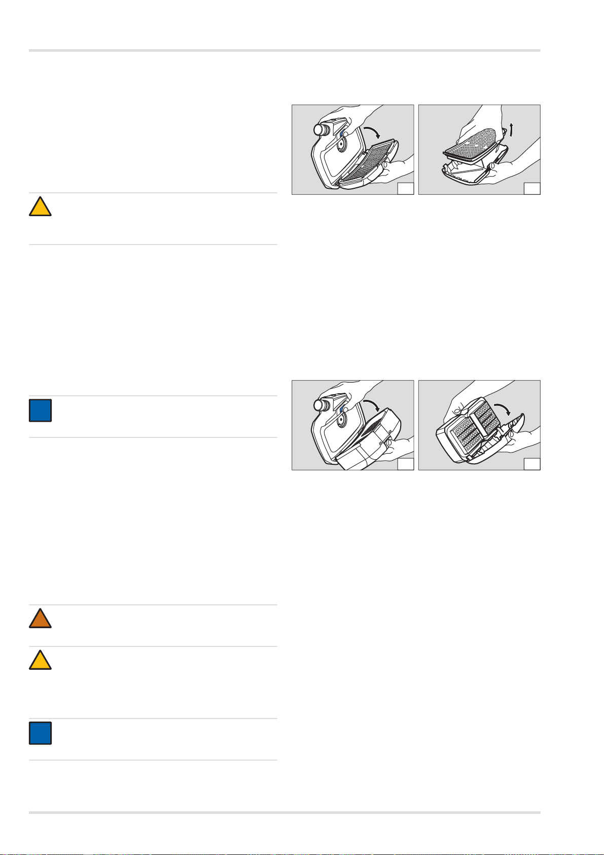
Partikelfilter
Filter abnehmen:
1. Filterverriegelungstaste betätigen.
2. Filter zusammen mit dem Spritzschutzdeckel herausklappen (Abbildung A).
3. Verbrauchtes Filter entnehmen (Abbildung B).
Filter einsetzen:
1. Gummidichtung am Filter auf Beschädigungen überprüfen.
2. Neuen Filter in den Spritzschutzdeckel einsetzen.
3. Filter zusammen mit dem Spritzschutzdeckel schräg in die
Gebläseeinheit einsetzen.
4. Filter mit dem Spritzschutzdeckel hineinklappen, so dass
er hörbar einrastet.
Gas- oder Kombinationsfilter
Filter abnehmen:
1. Korrekte Netzspannung der Stromversorgung überprüfen.
Die Betriebsspannung des Netzteils muss mit der Netzspannung übereinstimmen.
2. Ladegerät mit dem Netzteil verbinden.
3. Netzteil an die Stromversorgung anschließen.
4. Akku zunächst schräg in das Ladegerät setzen und dann
hineinklappen, so dass er hörbar einrastet.
5. Ladevorgang abwarten.
6. Wenn der Akku vollständig geladen ist, Akkuverriegelungstaste betätigen und Akku herausnehmen.
7. Netzteil von der Stromversorgung und Ladegerät vom
Netzteil trennen.
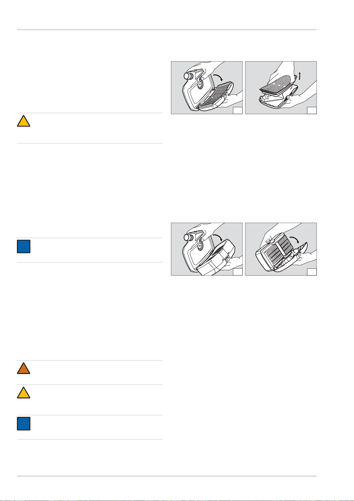
5.3.4 Filter wechseln
WARNUNG
Ohne Filter keine Schutzwirkung!
Gerät nicht ohne Filter verwenden.
VORSICHT
Beschädigung der Gebläseeinheit durch Eindringen
von Partikeln!
Beim Abnehmen des Filters darauf achten, dass über
die Ansaugöffnung keine Partikel in das Gerät gelangen.
HINWEIS
Je nach verwendetem Filtertyp unterscheidet sich der
Ablauf beim Wechseln des Filters.
1. Filterverriegelungstaste betätigen.
2. Filter zusammen mit dem Spritzschutzdeckel herausklappen (Abbildung A).
3. Spritzschutzdeckel demontieren:
a. Mittig auf die obere Kante des Spritzschutzdeckels drü-
cken, so dass er ausrastet.
b. Spritzschutzdeckel herausklappen (Abbildung B).
Filter einsetzen:
1. Gummidichtung am Filter auf Beschädigungen überprüfen.
2. Spritzschutzdeckel mit der unteren Kante schräg auf das
Filter stecken.
3. Spritzschutzdeckel aufdrücken, so dass er hörbar einrastet.
4. Filter zusammen mit dem Spritzschutzdeckel schräg in die
Gebläseeinheit einsetzen.
5. Filter mit dem Spritzschutzdeckel hineinklappen, so dass
er hörbar einrastet.
5.3.5 Vo lu menstrom und Warneinrichtungen prüfen
1. Sicherstellen, dass ein Filter eingesetzt ist (siehe Kapitel
5.3.4 auf Seite 12).
2. S teckanschluss des Atemschlauchs an die Gebläseeinheit
anschließen.
12 Dräger X-plore 8000
Page 13
Transport
3. Gebläseeinheit durch Drücken der Taste am Bedienfeld
einschalten.
Nach dem Einschalten führt das Gerät einen Selbsttest
durch. Wenn das Gerät nicht einwandfrei läuft oder Warneinrichtungen ansprechen, Störung beseitigen (siehe Kapitel 4 auf Seite 10).
4. Offenes Ende des Atemschlauchs mit der Handfläche abdecken.
Die Gebläseeinheit beginnt nach ca. 5 Sekunden intensiver zu laufen. Nach ca. 20 Sekunden wird ein Alarm ausgelöst.
Wenn das Gebläse die Drehzahl nicht verändert und kein
Alarm ausgelöst wird, Gebläseeinheit überprüfen lassen.
5. Wenn gewünscht, Gebläseeinheit durch erneutes Drücken
der Taste am Bedienfeld wieder ausschalten.
5.3.6 O-Ring am Steck- oder Bajonettanschluss der
Schläuche wechseln
1. Alten O-Ring mit dem O-Ring-Entferner an der Kerbe heraushebeln.
2. Neuen O-Ring in die vorgesehene Nut einsetzen.
6 Transport
Transport in der Originalverpackung oder in optional erhältlicher Transportbox.
7 Lagerung
Gesamtsystem lagern:
z Filter und Akku ausbauen.
z Komponenten in einem Behälter oder Schrank trocken und
schmutzfrei aufbewahren und vor direkter Sonnen- und
Wärmestrahlung schützen.
Akkus lagern:
z Stark entladene Akkus können bei längerer Lagerung be-
schädigt werden. Vor der Lagerung Akkus auf 50 bis 70 %
aufladen.
z Bei einer Lagerung von mehr als 6 Monaten Akkus zwi-
schenzeitlich aufladen.
z Akkus nicht längere Zeit außerhalb des empfohlenen Tem-
peraturbereichs lagern. Dies kann die verb leibende Kapazität und die Anzahl der möglichen Ladezyklen vermindern.
8Entsorgung
Dieses Produkt darf nicht als Siedlungsabfall entsorgt
werden. Es ist daher mit dem nebenstehenden Symbol
gekennzeichnet.
Dräger nimmt dieses Produkt kostenlos zurück. Informationen dazu geben die nationalen Vertriebsorganisationen und Dräger.
Batterien und Akkus dürfen nicht als Siedlungsabfall
entsorgt werden. Sie sind daher mit dem
nebenstehenden Symbol gekennzeichnet. Batterien
und Akkus gemäß den geltenden Vorschriften bei
Batterie-Sammelstellen entsorgen.
9 Technische Daten
Gesamtes System
Volumenstrom Atems chutzhaube/
-helm/-visier:
Volumenstrom Halb-/Vollmaske: 115/130/145 L/min
Nenneinsatzdauer: 4 Stunden
Arbeitstemperatur:
Arbeits-/Lagerluftfeuchte:
Lagertemperatur:
1)
1)
1)
Geräuschpegel: ca. 64 dB(A)
Schutzart: IP 65
1) Ladegerät und Akkus siehe separate Angaben in diesem Kapitel.
Andere Komponenten siehe entsprechende Gebrauchsanweisung.
Akkus
Arbeitstemperatur: -10 °C bis 60 °C
Arbeits-/Lagerluftfeuchte: 95 % relative Feuchte
Lagertemperatur: -20 °C bis 50 °C
Ladetemperatur: 0 °C bis 50 °C
Standardakku
Ladedauer: < 4 Stunden
Betriebsdauer nach einer Aufla-
dung:
Nennspannung: 10,8 V
Nennkapazität: 3,35 Ah
Leistungsabgabe: 36 Wh
Langzeitakku
Ladedauer: < 4 Stunden
Betriebsdauer nach einer Aufla-
dung:
Nennspannung: 10,8 V
Nennkapazität: 6,70 Ah
Leistungsabgabe: 72 Wh
1) Variiert je nach eingestelltem Volumenstrom sowie verwendetem
Filter- und Atemanschlusstyp
Ladegerät
Eingangsspannung: 15 V
Eingangsstrom: 4A
Ausgangsspannung: 9 - 12,6 V
Ausgangsstrom: 4A
Schutzart: IP 30
170/190/210 L/min
mit Standardakku
8 Stunden
mit Langzeitakku
-10 °C bis 60 °C
95 % relative Feuchte
-20 °C bis 60 °C
ca. 4 Stunden
ca. 8 Stunden
1)
1)
Dräger X-plore 8000 13
Page 14

Bestellliste
Arbeitstemperatur: 0 °C bis 50 °C
Arbeits-/Lagerluftfeuchte: 95 % relative Feuchte
Lagertemperatur: -20 °C bis 50 °C
10 Bestellliste
Komponenten
Pos. 1)Benennung und Beschreibung Bestellnr.
1 Dräger X-plore 8500 (IP) R59500
2 Dräger X-plore 8000 Standardakku R59565
3 Dräger X-plore 8000 Langzeitakku R59585
4 Dräger X-plore 8000 Standardgürtel R59700
5 Dräger X-plore 8000 Gürtel, dekontami-
nierbar
6 Dräger X-plore 8000 Standardschlauch
(für Halb-/Vollmasken)
7 Dräger X-plore 8000 Standardschlauch
(für Hauben)
8 Dräger X-plore 8000 Standardschlauch
(für Helme und Visiere)
9 Dräger X-plore 8000 Flexibler Schlauch
(für Halb-/Vollmasken)
10 Dräger X-plore 8000 Flexibler Schlauch
(für Hauben)
11 Dräger X-plore 8000 Flexibler Schlauch
(für Helme und Schutzvisiere)
12 Dräger X-plore 8000 Filter P R SL 6739535
13 Dräger X-plore 8000 Filter A2 6739580
14 Dräger X-plore 8000 Filter A2 P R SL 6739545
15 Dräger X-plore 8000 Filter A1B1E1K1
Hg P R SL
16 Dräger X-plore 8000 Standardhaube,
kurz (S/M)
17 Dräger X-plore 8000 Standardhaube,
kurz (L/XL)
18 Dräger X-plore 8000 Standardhaube,
lang (S/M)
19 Dräger X-plore 8000 Standardhaube,
lang (L/XL)
20 Dräger X-plore 8000 Premiumhaube,
kurz (S/M)
21 Dräger X-plore 8000 Premiumhaube,
kurz (L/XL)
22 Dräger X-plore 8000 Premiumhaube,
lang (S/M)
23 Dräger X-plore 8000 Premiumhaube,
lang (L/XL)
24 Dräger X-plore 8000 Helm mit Visier,
schwarz
25 Dräger X-plore 8000 Helm mit Visier,
weiß
26 Dräger X-plore 8000 Schutzvisier R59900
R59710
R59630
R59620
R59640
R59610
R59600
R59650
6739555
R59800
R59810
R59820
R59830
R59840
R59850
R59860
R59870
R58325
R59910
Pos. 1)Benennung und Beschreibung Bestellnr.
27 Dräger X-plore 6300 EPDM/PMMA R55800
28 Dräger X-plore 6530 EPDM/PC R55795
29 Dräger X-plore 6570 SI/PC R55790
30 Dräger X-plore 4740 SI S/M R55875
31 Dräger X-plore 4740 SI M/L R55874
32 Dräger FPS 7000 EPDM-S1-PC-CR R56502
33 Dräger FPS 7000 EPDM-M2-PC-CR R56310
34 Dräger FPS 7000 EPDM-L2-PC-CR R56503
35 Dräger X-plore 8000 Standardladegerät R59580
1) Siehe Konfigurationsmatrix (Configuration Matrix) auf Seite 243.
Zubehörteile
1)
Pos.
1) Siehe Konfigurationsmatrix (Configuration Matrix) auf Seite 243.
Benennung und Beschreibung Bestellnr.
36 Dräger X-plore 8000 Verschlussstopfen
(für Schlauchanschluss der Gebläseeinheit)
37 Dräger X-plore 8000 Verschlussstopfen
(für Ansaugöffnung der Gebläseeinheit)
38 Dräger X-plore 8000 Komfortpolster R59730
39 Gurtverlängerung für X-plore 8000
Standardgürtel, 35 cm
40 Gurtverlängerung für X-plore 8000 Gür-
tel,dekontaminierbar, 35 cm
41 Dräger X-plore 8000 Aufbewahrungs-
box
R59563
R59564
R59750
R59760
R59690
Ersatzteile
Pos. Benennung und Beschreibung Bestellnr.
42 Dräger X-plore 8000 Spritzschutzdeckel 6739725
43 Gurtendenklammern, Set R59705
44 Steckschnalle, Set R59715
45 O-Ring für Steckanschluss X-plore 8000
Haube und Gebläseeinheit
46 O-Ring für Bajonettanschluss X-plore
8000 Helm und Schutzvisier
47 O-Ring-Entferner R21402
R59631
R59632
Reinigungs- und Desinfektionsmittel
Pos. Benennung und Beschreibung Bestellnr.
48
Sekusept® Cleaner, 4 x 2 L
49
Incidin® Rapid, 6 L
andere Gebinde auf Anfrage
50
Incides®N Desinfektionstücher,
6 Dosen a 90 Tücher
7904071
R61880
6570001
14 Dräger X-plore 8000
Page 15

Contents
Contents
1 For your safety . . . . . . . . . . . . . . . . . . . . . . . . . . .16
1.1 General safety statements . . . . . . . . . . . . . . . . . . .16
1.2 Definitions of alert icons . . . . . . . . . . . . . . . . . . . . .16
2 Description . . . . . . . . . . . . . . . . . . . . . . . . . . . . . .16
2.1 System overview . . . . . . . . . . . . . . . . . . . . . . . . . . .16
2.2 Components . . . . . . . . . . . . . . . . . . . . . . . . . . . . . .16
2.2.1 Fan unit . . . . . . . . . . . . . . . . . . . . . . . . . . . . . . . . . .16
2.2.2 Filter and facepieces . . . . . . . . . . . . . . . . . . . . . . . .17
2.2.3 Breathing hoses . . . . . . . . . . . . . . . . . . . . . . . . . . .17
2.2.4 Carrying systems . . . . . . . . . . . . . . . . . . . . . . . . . .17
2.2.5 Rechargeable batteries . . . . . . . . . . . . . . . . . . . . . .17
2.2.6 Battery chargers . . . . . . . . . . . . . . . . . . . . . . . . . . .17
2.3 Functional description . . . . . . . . . . . . . . . . . . . . . . .18
2.3.1 Warning devices . . . . . . . . . . . . . . . . . . . . . . . . . . .18
2.4 Intended use . . . . . . . . . . . . . . . . . . . . . . . . . . . . . .18
2.5 Limitations on use . . . . . . . . . . . . . . . . . . . . . . . . . .18
2.6 Approvals . . . . . . . . . . . . . . . . . . . . . . . . . . . . . . . .18
2.7 Explanation of type-identifying marking and
symbols . . . . . . . . . . . . . . . . . . . . . . . . . . . . . . . . . .18
2.7.1 Name plates . . . . . . . . . . . . . . . . . . . . . . . . . . . . . .18
2.7.2 Packaging . . . . . . . . . . . . . . . . . . . . . . . . . . . . . . . .19
3 Use . . . . . . . . . . . . . . . . . . . . . . . . . . . . . . . . . . . . .19
3.1 Preconditions for use . . . . . . . . . . . . . . . . . . . . . . .19
3.2 Preparations for use . . . . . . . . . . . . . . . . . . . . . . . .19
3.2.1 Assembling the carrying system . . . . . . . . . . . . . . .19
3.2.2 Donning the device . . . . . . . . . . . . . . . . . . . . . . . . .19
3.2.3 Connecting the facepiece . . . . . . . . . . . . . . . . . . . .19
3.2.4 Switching on the device . . . . . . . . . . . . . . . . . . . . . 19
3.3 During use . . . . . . . . . . . . . . . . . . . . . . . . . . . . . . . .20
3.3.1 Adjusting the flow rate . . . . . . . . . . . . . . . . . . . . . . .20
3.3.2 Warnings and alarms . . . . . . . . . . . . . . . . . . . . . . .20
3.4 After use . . . . . . . . . . . . . . . . . . . . . . . . . . . . . . . . .20
3.5 General user tasks . . . . . . . . . . . . . . . . . . . . . . . . . 2 0
3.5.1 Attaching comfortable padding for standard belt . .2 0
3.5.2 Attaching belt extension to carrying system . . . . . .20
4 Troubleshooting . . . . . . . . . . . . . . . . . . . . . . . . . .20
4.1 Warnings . . . . . . . . . . . . . . . . . . . . . . . . . . . . . . . . .20
4.2 Alarms . . . . . . . . . . . . . . . . . . . . . . . . . . . . . . . . . . .21
5 Maintenance . . . . . . . . . . . . . . . . . . . . . . . . . . . . .21
5.1 Maintenance intervals . . . . . . . . . . . . . . . . . . . . . . .21
5.2 Cleaning and disinfecting . . . . . . . . . . . . . . . . . . . .21
5.2.1 Clean and disinfect the device . . . . . . . . . . . . . . . .21
5.3 Maintenance work . . . . . . . . . . . . . . . . . . . . . . . . . .21
5.3.1 Visual inspection . . . . . . . . . . . . . . . . . . . . . . . . . . .21
5.3.2 Checking the battery capacity . . . . . . . . . . . . . . . . .22
5.3.3 Replacing or charging the rechargeable battery . . .22
5.3.4 Replacing the filter . . . . . . . . . . . . . . . . . . . . . . . . .22
5.3.5 Checking the flow rate and warning devices . . . . . .22
5.3.6 Replacing the O-ring at plug-in or bayonet-type hose
connector . . . . . . . . . . . . . . . . . . . . . . . . . . . . . . . .23
6 Transport . . . . . . . . . . . . . . . . . . . . . . . . . . . . . . . 23
7 Storage . . . . . . . . . . . . . . . . . . . . . . . . . . . . . . . . . 23
8 Disposal . . . . . . . . . . . . . . . . . . . . . . . . . . . . . . . . 23
9 Technical data . . . . . . . . . . . . . . . . . . . . . . . . . . . 23
10 Order list . . . . . . . . . . . . . . . . . . . . . . . . . . . . . . . 24
Dräger X-plore® 8000 15
Page 16
For your safety
!
!
i
i
1 For your safety
1.1 General safety statements
z Before using this product, carefully read these Instructions
for Use and those of the associated components.
z Strictly follow the Instructions for Use. The user must fully
understand and strictly observe the instructions. Use the
product only for the purposes specified in the Intended use
section of this document.
z Do not dispose of the Instructions for Use. Ensure that they
are retained and appropriately used by the product user.
z Only trained and competent users are permitted to use this
product.
z Follow the local and national guidelines pertaining to this
product.
z Only trained and competent personnel are permitted to in-
spect, repair and service the product.
z Use only genuine Dräger spare parts and accessories, or
the proper functioning of the product may be imp aired.
z Do not use a faulty or incomplete product. Do not modify
the product.
z Notify Dräger in the event of any product or component
fault or failure.
1.2 Definitions of alert icons
The following warning symbols are used in this document to
provide and highlight areas of the associated text that requ ire
a greater level of awareness from the user. The meanings of
the symbols are as follows:
WARNING
Indicates a potentially hazardous situation
which, if not avoided, could result in death or serious
injury.
CAUTION
Indicates a potentially hazardous situation which, if not
avoided, could result in physical injury, or damage to
the product or environment. It may also be used to
warn against unsafe practices.
NOTICE
Indicates additional information on how to use the
product.
Ź Illustration of the system overview on the fold-out page
(Figure A)
A complete device includes:
1 Breathing hose
2 Facepiece (example with helmet)
3 Carrying system
4 Fan unit with filter and rechargeable battery
If applicable, accessory components (without illustration)
NOTICE
i
i
For an overview of the device combinations and the
corresponding protection class, refer to the Configuration Matrix on page 243.
The numbers in the first line of the Configuration Matrix
correspond to the positions in the order list.
The listed components are designated for use with the
X-plore 8500 fan unit (order list pos. 1) and the rechargeable batteries (pos. 2 and 3).
Dräger would be happy to answer any questions you
may have regarding device configuration.
2.2 Components
2.2.1 Fan unit
The fan unit is the central device component.
Device characteristics:
z Control panel with display of current system status
z Electronic monitoring of device functions
{ Flow rate
{ Residual particle filter capacity
{ Rechargeable battery capacity
{ Detection if hoses or filters are disconnected from the
device
z Automatic detection of the employed type of facepiece
(half/full face mask or hood/helmet/protective visor) and
corresponding adjustment of the flow rate range
z Three-stage selection of flow rate
z Optical detection of filter type by colour coding (coloured
dot on filter)
2 Description
2.1 System overview
The Dräger X-plore®80001) powered air purifying respirator
may be composed of different components depending on its
field of application and the required protection class. Observe
particularly the filter operating limits (see Instructions for Use
of the filters).
1) X-plore® is a registered trademark of Dräger.
16 Dräger X-plore 8000
Ź Illustration of fan unit front on the fold-out page (Figure B)
1 Tube connection
2 Control panel
3 Suction inlet
4 Splash guard cover
5 Filter (not enclosed with fan unit)
6 Filter lock button
Page 17
Description
i
i
Ź Illustration of fan unit rear on the fold-out page (Figure C)
1 Carrying system socket
2 Name plate
3 Carrying system lock button
4 Battery lock button
5 Rechargeable battery (not enclosed with fan unit)
Control panel
Ź Illustration on the fold-out page (Figure D)
1 Rechargeable battery status indicator
2 Residual particle filter capacity indicator
3 On/off button
4 Flow rate indicator
5 Reduce flow rate
6 Increase flow rate
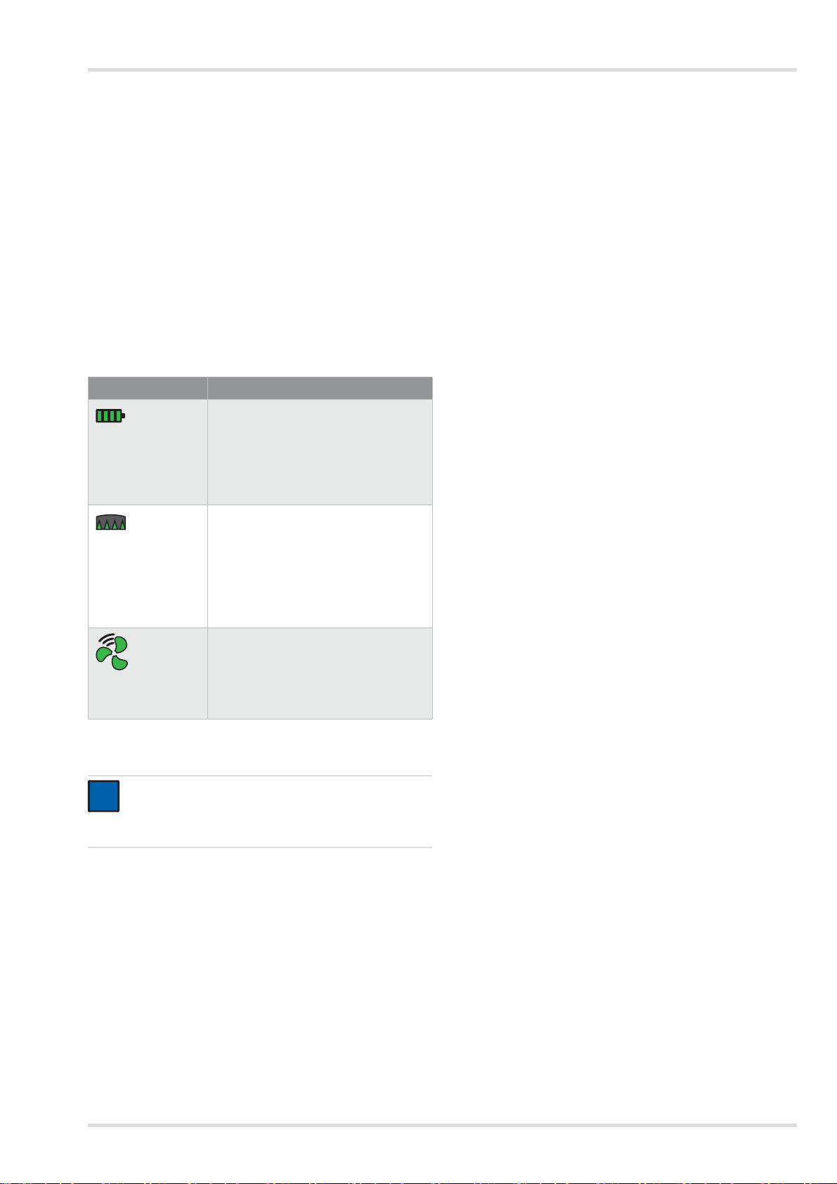
Explanation of control panel indicators
Indicator Explanation
Battery capacity depending on number
of displayed segments:
Segments light up
in green.
> 75 % (4 segments)
> 50 % (3 segments)
> 25 % (2 segments)
< 25 % (1 segment)
Residual capacity of particle filter 1) depending on number of displayed seg-
Segments light up
ments:
in green.
> 75 % (4 segments)
> 50 % (3 segments)
> 25 % (2 segments)
< 25 % (1 segment)
Flow rate intensity depending on number of displayed segments:
Segments light up
in green.
1) The residual capacity of the gas filter or the gas filter components
of the combination filter cannot be indicated.
high flow rate (3 segments)
medium flow rate (2 segments)
low flow rate (1 segment)
NOTICE
Warnings or alarms are indicated by flashing yellow or
red LEDs. For an explanation of malfunction indicators, see section 4 on page 20.
2.2.2 Filter and facepieces
Filter and facepieces are described in separate Instructions for
Use.
2.2.3 Breathing hoses
The following breathing hoses are available:
z standard hose
z flexible hose for increased comfort
z bayonet-type connector (helmet and protective visor)
z round-thread connector (half/full face mask)
2.2.4 Carrying systems
Ź Illustration on the fold-out page (Figure E)
1 Connection plate
2 Webbing
3 Clips on ends of the belt
4Buckle
The following carrying systems are available:
z Standard belt
The standard belt consists of a textile webbing and press
studs to attach comfortable padding.
z Decontaminable belt:
The decontaminable belt has a smooth plastic webbing
and is particularly recommended for decontamination.
2.2.5 Rechargeable batteries
Ź Illustration on the fold-out page (Figure F)
1 Battery lock button
2 Battery status indicator
3 Button to display battery capacity
4 Name plate
The rechargeable Li-ion batteries are specially designed for
use with the powered air purifying respirator. A long-life rechargeable battery is also available in addition to the standard
rechargeable battery.
The battery status indicator shows the battery capacity while
you charge the unit with the standard charger or when you
push the button. The segments of the battery status indicator
are flashing while you charge the unit.
The battery status indicator corresponds to that on the control
panel of the fan unit (see section 2.2.1 on page 16).
The rechargeable batteries reach their full capacity after 5
charge and discharge cycles. The standard charge takes approx. 3 hours.
In cases where the battery has been completely drained
charging may take up to 4 hours longer. During this time the
battery status indicator is not supported.
T o prevent damage to or explosion of the rechargeable battery ,
charging is limited to a temperature range of 0 to 50 °C. If this
temperature range is exceeded or falls below, charging will
stop automatically and continue once the temperature range is
reached again.
2.2.6 Battery chargers
Standard battery charger
Ź Illustration on the fold-out page (Figure G)
1StatusLED
2 Power supply unit
3 Battery compartment
Both breathing hoses are available for each of the following facepiece types:
z plug-in connector (hood)
Dräger X-plore 8000 17
Page 18
Description
i
i
Explanation of the status LED
Indicator Explanation
Rechargeable battery is inserted and
fully charged (standby mode)
Status LED is
green.
Rechargeable battery is inserted and
being charged.
Status LED is flashing green.
Rechargeable battery is not inserted.
Status LED is red.
Malfunction
Status LED is flash-
ing red.
When the rechargeable battery is fully charged, the charger
switches automatically to standby. In stand by mode, the rechargeable battery stays fully charged at all times. In this mode
the rechargeable battery is neither overcharged nor damaged.
2.3 Functional description
The powered air purifying respirator is a respiratory protective
device depending on circulating air.
It filters the ambient air and makes it available as breathable
air. The device continuously takes in ambient air through the filter. The filter absorbs harmful substances depending on the filter type. In this way, the ambient air is recycled and finally
reaches the facepiece. There it is available as breathable air.
A continuous overpressure in the facepiece prevents ambient
air from penetrating.
2.3.1 Warning devices
Malfunctions during operation are indicated by warning devices.
2.4 Intended use
Depending on the employed filter type, the device protects
against particles, gases and vapours or combinations hereof.
2.5 Limitations on use
The device is not suitable for use:
z in explosion-hazard areas (Ex-areas)
z when there is a suspicion of contaminants with low warning
properties (smell, taste, irritation of eyes and airways)
z in unventilated tanks, pits, canals etc.
2.6 Approvals
The device is approved according to
z EN 12941:2009-02
z EN 12942:2009-02
Therefore the device complies with directive 89/686/EEC on
personal protective equipment.
Additional directives as part of the CE marking:
z EMC directive (2004/108/EC)
z R&TTE directive (1999/5/EC)
z NSR directive (2006/95/EC)
z RoHS directive (2011/65/EU)
2.7 Explanation of type-identifying marking
and symbols
2.7.1 Name plates
Ź Illustration of name plates on page 4
Fan unit: Figure H
Standard battery
charger:
Rechargeable bat-
tery:
Figure I
Figure J
The warning devices include:
z optical alarm (display on control panel)
z acoustic alarm
z vibration alarm
NOTICE
The vibration alarm is triggered in addition to the
acoustic alarm. Depending on the thickness and material of the clothing, the vibration alarm might not be per-
ceived.
The fan unit always delivers the same default flow rate.
If in the foreseeable future the fan unit will no longer be able to
deliver the default flow rate (e.g. due to increasing saturation
of the particle filter), a warning or alarm is triggered.
18 Dräger X-plore 8000
1 Product name
2 International Protection Code
3 Fulfilled EN standards
4 Symbol "Follow instructions for use"
5 WEEE symbol "Separate collection of electrical and elec-
tronic equipment"
6 Country of production
7 Manufacturer
8 CE marking
9 DataMatrix code with part and serial number
10 Serial number
1 1 Article code
12 Only for indoor use, not for outdoor use
13 Maximum ambient temperature
14 Electrical data
15 Pin assignment
16 Recycling symbol
17 Warning notice
Page 19
Use
<95%
-20°C
+70°C
04733412.eps
Information on year of manufacture
The year of manufacture results from the 3rd letter of the serial
number: F = 2014, G = omitted, H = 2015, I = omitted, J = 2016,
K = 2017 etc.
Example: Serial number ARFH-0054: The third letter is F, the
year of manufacture is therefore 2014.
2.7.2 Packaging
Follow the Instructions for Use
Maximum storage area humidity
Storage temperature range
3 Use
3.1 Preconditions for use
z The ambient conditions (in particular type and concentra-
tion of the contaminants) must be known.
z The oxygen content of the ambient air must not drop below
the following limit values:
{ At least 17 vol.% oxygen in all European countries ex-
cept for the Netherlands, Belgium and the UK
{ At least 19 vol.% oxygen in the Netherlands, Belgium,
the UK, Australia and New Zealand.
{ At least 19.5 vol.% oxygen in the USA
Observe the national guidelines in other countries.
3.2 Preparations for use
Perform the following activities outside the danger zone:
1. Select components of the powered air purifying respirator
(filter, facepiece, etc.) according to the required protection
class and task (see Configuration Matrix on page 243).
2. Perform a visual inspection (see section 5.3.1 on page 21).
3. Check battery capacity (see section 5.3.3 on page 22).
4. Insert filter (see section 5.3.4 on page 22).
5. Assemble the carrying system (see section 3.2.1 on page
19).
6. Attach accessories if applicable (see section 3.5 on page
20).
7. Don the device (see section 3.2.2 on page 19).
8. Connect facepiece (see section 3.2.3 on page 19)
9. Switch on the device (see section 3.2.4 on page 19).
3.2.1 Assembling the carrying system
1. Position the connection plate of the carrying system on the
fan unit socket. The arrows on the connection plate and the
socket go together.
2. Push down connection plate until you can hear it snap into
place in the socket.
3.2.2 Donning the device
1. Adjust the carrying system belt to approximately the correct
circumference.
2. Put on belt and close buckle. The device is located on the
back of the user.
3. Tighten belt and fasten protruding ends with clips on ends
of the belt.
3.2.3 Connecting the facepiece
1. Connect the plug-in connector of the breathing hose to the
fan unit.
2. Connect the other end of the breathing hose to the
facepiece.
WARNING
!
Penetration of ambient air!
Make sure that all components are securely and firmly
connected to each other before use.
3.2.4 Switching on the device
1. Switch on the fan unit by pushing the button on the control panel for approx. 2 seconds.
After switching on, the device performs a self-test.
2. Correct malfunction if the device fails to work properly or
warning devices are triggered (see section 4 on page 20).
3. Don the facepiece (see Instructions for Use of the corresponding facepiece).
4. Adjust the flow rate using the and buttons as desired.
Dräger X-plore 8000 19
Page 20
Troubleshooting
!
3.3 During use
WARNING
Health hazard!
Leave the danger zone immediately in case of:
z Decreasing or interrupted air supply (e.g. after fan
failure)
In the hood/helmet/protective visor facepiece type,
carbon dioxide can quickly build up or lack of oxygen may occur. Noxious ambient air may also penetrate the hood.
z Odour or taste developing in the facepiece (filter
break). The residual capacity of the ga s filter or the
gas filter components of the combination filter are
exhausted.
z Drowsiness, dizziness, or other complaints
z Damage to the equipment
z Other indicated alarms (see section 4 on page 20)
Breathing hoses or other components involve the risk
of getting caught. This may damage the device and interrupt the air supply!
Handle the device with care.
Breathing in during heavy work while wearing the
hood/helmet/protective visor facepiece type may result
in negative pressure and the penetration of unfiltered
ambient air!
Increase the flow rate to prevent this from happening.
3.4 After use
Do the following:
1. Leave the hazardous area.
2. Remove the facepiece (see Instructions for Use of the corresponding facepiece).
3. Switch off the fan unit by pushing the button on the control panel for approx. 2 seconds.
4. Open the carrying system belt and take off the device.
5. Clean and disinfect the device (see section 5.2 on page
21).
3.5 General user tasks
3.5.1 Attaching comfortable padding for standard belt
Attach comfortable padding to the standard belt with the press
studs.
3.5.2 Attaching belt extension to carrying system
If needed, the belt extension is attached to the belt buckle.
4 Troubleshooting
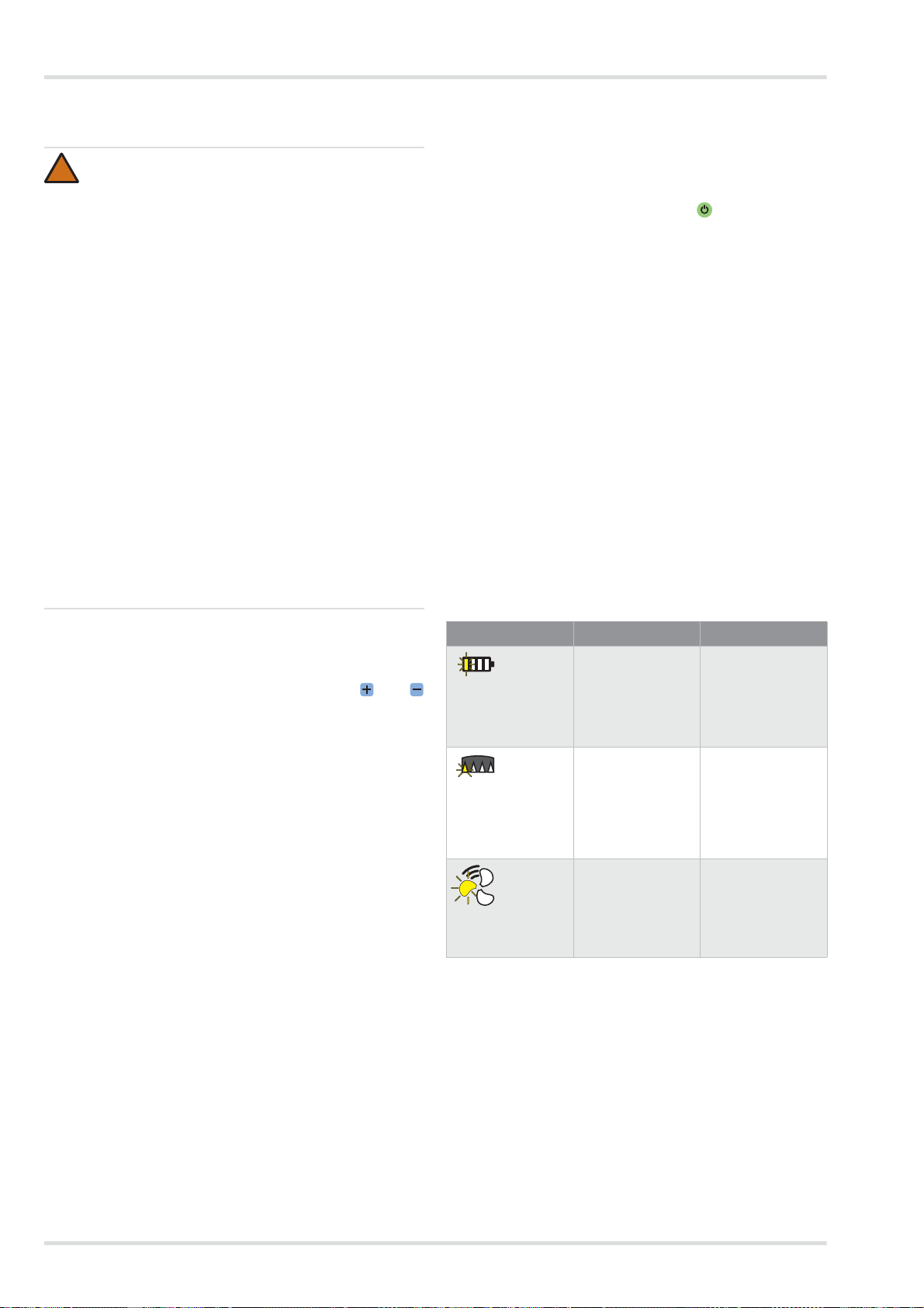
4.1 Warnings
The type of warning is indicated optically by yellow flashing of
the corresponding indicator. In addition, an acoustic warning
signal and the vibration alarm are triggered.
3.3.1 Adjusting the flow rate
If necessary (e.g. during increased physical exertion), the flow
rate must be adjusted during operation using the and
buttons.
3.3.2 Warnings and alarms
If a warning appears, leave the working area promptly in view
of the potentially hazardous situation.
Lower the flow rate to increase the period of service if a warning appears. (Only possible if the lowest level has not already
been chosen.) By lowering the flow rate you can e.g. extend
the battery runtime.
If an alarm is triggered, leave the working area immedi ately
without any delay.
Check the function of the device after a warning or alarm has
been triggered (see section 4 on page 20).
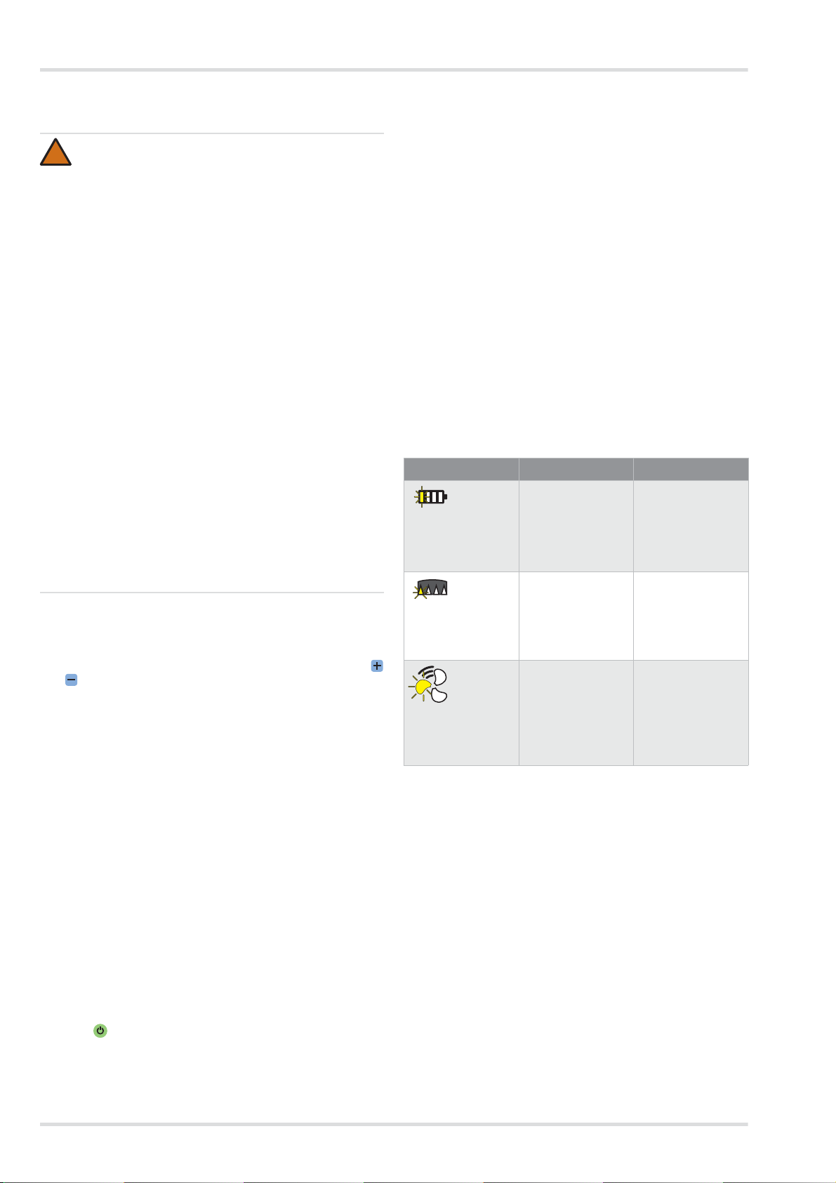
Fault Cause Remedy
A segment of the
battery status indicator is flashing
yellow.
A segment of the
particle filter residual capacity indicator is flashing
yellow.
A segment of the
flow rate indicator
is flashing yellow.
The residual runtime of the rechargeable battery
is low
(< 30 minutes).
The particle filter
residual capacity is
low (< 20 %).
Malfunction during
switch-on (e.g.
caused by missing
hose or filter).
Recharge the battery soon or replace with fully
charged battery
(see section 5.3.3
on page 22).
Change particle or
combination filter
soon (see section
5.3.4 on page 22).
Verify device function and prepare
again for use (see
section 3.2 on
page 19).
20 Dräger X-plore 8000
Page 21
Maintenance
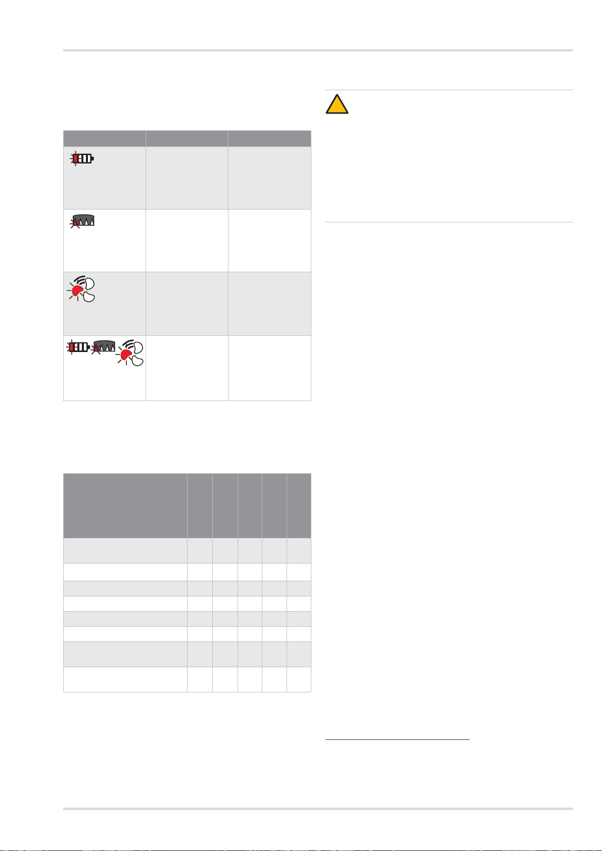
4.2 Alarms
The type of alarm is indicated optically by red flashing of the
corresponding indicator. In addition, an acoustic alarm and the
vibration alarm are triggered.
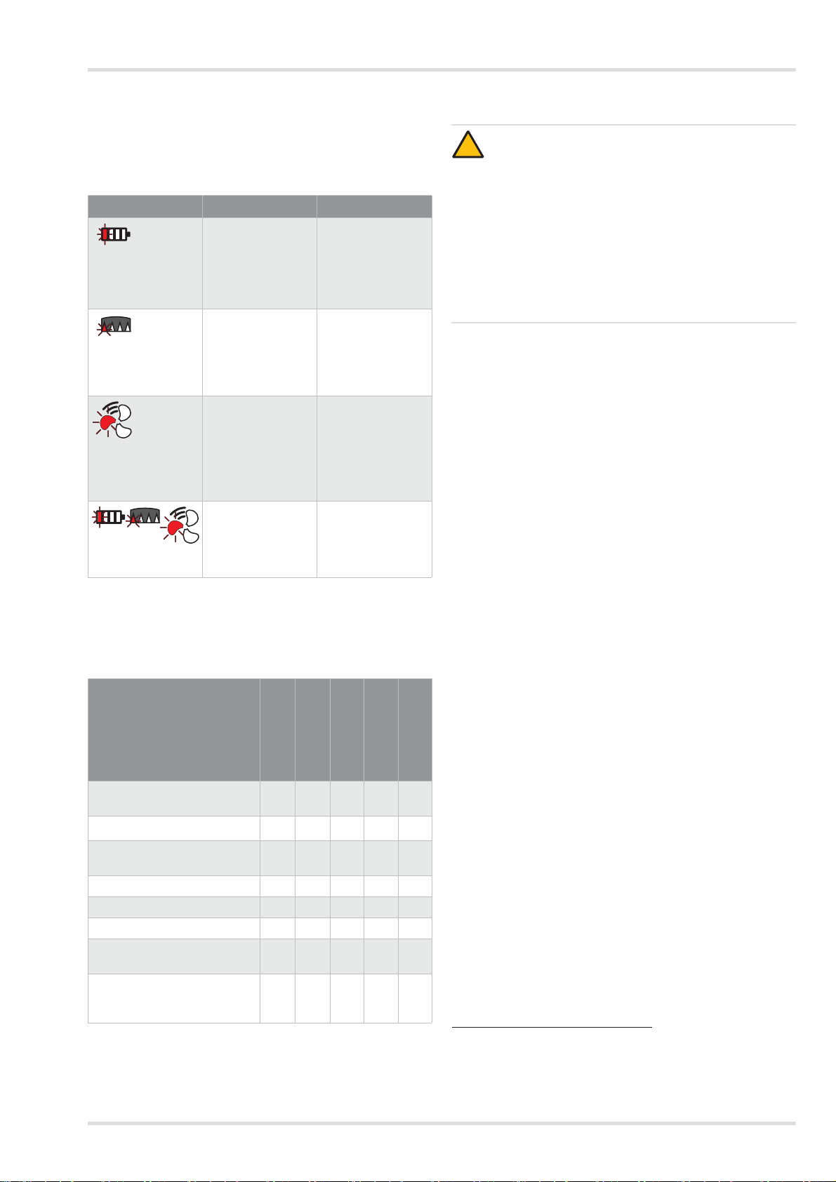
Fault Cause Remedy
A segment of the
battery status indicator is flashing
red.
A segment of the
particle filter residual capacity indicator is flashing red.
A segment of the
flow rate indicator
is flashing red.
One segment at a
time is flashing
red.
The residual runtime of the rechargeable battery
is almost exhausted (< 10 minutes).
The particle filter
residual capacity is
almost exhausted
(< 10 %).
Faulty breathing air
supply during operation (e.g. caused
by missing hose or
filter).
General system error
Recharge the battery or replace with
fully charged battery (see section
5.3.3 on page 22).
Change particle or
combination filter
(see section 5.3.4
on page 22).
Verify device function and prepare
again for use (see
section 3.2 on
page 19).
Device must be
checked by Dräger
Service.
5 Maintenance
5.1 Maintenance intervals
Work to do
Annually
After use
Before use
Clean and disinfect the device
Visual inspection X
Check battery capacity X
Replace rechargeable battery X
Charge rechargeable battery X
Replace filter X
Check flow rate and warning
devices
Replace O-ring at plug-in or
bayonet-type hose connector
1) for gas-tight packed devices, otherwise every 6 months
X
Every 2 years
1)
X
1)
X
X X
As necessary
X
5.2 Cleaning and disinfecting
CAUTION
!
Potential damage to components!
Only use the prescribed processes and the cleaning
and disinfection agents specified for cleaning and disinfecting. Other agents, methods, dosages and contact
times may damage the components.
Health hazard!
The undiluted agents are damaging to health if they
come into direct contact with the eyes or skin. Wear
safety goggles and protective gloves when working
with these agents.
5.2.1 Clean and disinfect the device
1. Dismantling the device:
a. Separate breathing hose, facepiece and fan unit from
each other.
b. Disconnect the carrying system from the fan unit.
c. If available, dismantle any accessories (e.g. hose and
device sleeves).
d. Dismantle splash guard cover and filter (see section
5.3.4 on page 22).
2. Clean the facepiece according to the appropriate Instructions for Use.
3. Cleaning the breathing hose and carrying system:
a. Clean all parts with lukewarm water and Sekusept
Cleaner1) with a soft cloth (max. temperature: 30 °C;
concentration depending on the degree of con tamina-
tion: 0.5 - 1 %).
b. Rinse all parts thoroughly under running water.
c. Prepare a disinfectant bath of water and
d. Place all parts to be disinfected into the disinfectant
e. Rinse all parts thoroughly under running water.
f. Allow all parts to air-dry or dry them in the drying cabi-
4. Clean and disinfect fan unit and splash guard cover using
Incides
In cases of strong contamination, the fan unit can be rinsed under running water as follows.
1. Make sure the rechargeable battery remains inserted. Water must not enter the battery compartment.
2. Close suction inlet and tube connection with protective
caps (available as accessories).
®
Incidin
1.5 %).
bath (duration: 15 minutes).
net (temperature: 60 °C). Keep away from direct sunlight.
Rapid2) (temperature: 30 °C; concentration:
®
N disinfectant cloths1).
5.3 Maintenance work
5.3.1 Visual inspection
Check all parts thoroughly and replace damaged parts if necessary. C heck particularly the filter sealing surface on the fan
unit for damage (e.g. scratches) or contamination.
®
1) Sekusept® and Incides® are registered trademarks of Ecolab
Deutschland GmbH.
®
2) Incidin
Dräger X-plore 8000 21
is a registered trademark of Ecolab USA Inc.
Page 22
Maintenance
!
i
i
!
!
i
i
02633412.eps
A
02733412.eps
B
B
02933412.eps
02833412.eps
A
5.3.2 Checking the battery capacity
1. Press the button to display the battery capacity on the rechargeable battery.
2. Read the battery status indicator.
3. If the battery capacity is insufficient for the planned period
of service:
Replace or charge rechargeable battery (see section 5.3.3
on page 22).
5.3.3 Replacing or charging the rechargeable battery
CAUTION
A short circuit could damage the rechargeable battery!
Make sure that the battery terminals do not come into
contact with metal during storage.
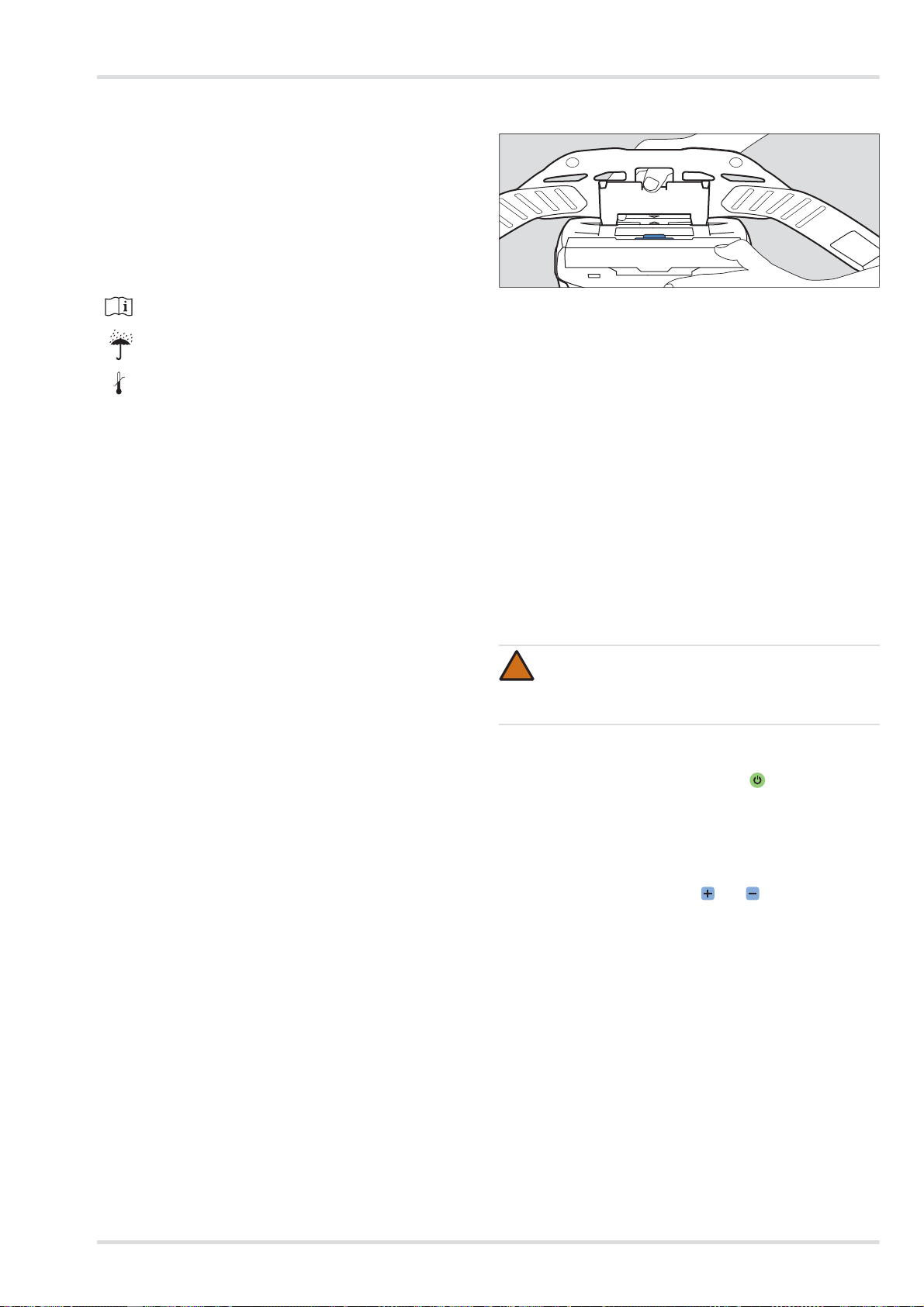
Removing the rechargeable battery:
1. Fold up carrying system if necessary.
2. Push battery lock button. Ensure that the rechargeable battery does not fall down.
3. Remove rechargeable battery.
Inserting the rechargeable battery:
1. Fold up carrying system if necessary.
2. Position the rechargeable battery at an angle in the battery
compartment and then fold it in until it snaps audibly into
place.
Particle filter
Removing the filter:
1. Push filter lock button.
2. Fold out filter together with the splash guard cover (Figure
A).
3. Remove used filter (Figure B).
Inserting the filter:
1. Check rubber seal on filter for damage.
2. Insert new filter into splash guard cover.
3. Position filter together with splash guard cover at an angle
into the fan unit.
4. Fold in filter with splash guard cover until it snaps audibly
into place.
Gas or combination filter
Removing the filter:
Charging the battery:
NOTICE
Always disconnect the charger from the power supply
if not in use.
1. Check to make sure that voltage of mains supply is correct.
The operational voltage of the power supply unit must
match the mains supply voltage.
2. Connect charger to power supply unit.
3. Connect the power supply unit to the mains supply.
4. Position the rechargeable battery at an angle in the charger
and then fold it in until it snaps audibly into place.
5. Wait for the end of the charging process.
6. When the rechargeable battery is fully charged, push the
battery lock button and remove the battery.
7. Disconnect the power supply unit and charger from the
mains supply.
5.3.4 Replacing the filter
WARNING
No protection without filter!
Do not use the device without filter.
CAUTION
Damage to fan unit due to penetration of particles!
Make sure when you remove the filter that no particles
enter the device through the suction inlet.
NOTICE
The filter changing process may differ depending on
the filter type used.
1. Push filter lock button.
2. Fold out filter together with the splash guard cover (Figure
A).
3. Dismantling the splash guard cover:
a. Press on the centre of the upper splash guard cover
edge until it snaps out.
b. Fold out splash guard cover (Figure B).
Inserting the filter:
1. Check rubber seal on filter for damage.
2. Place splash guard cover with its lower edge at an angle on
the filter.
3. Push on splash guard cover until it snaps audibly into
place.
4. Position filter together with splash guard cover at an angle
into the fan unit.
5. Fold in filter with splash guard cover until it snaps audibly
into place.
5.3.5 Checking the flow rate and warning devices
1. Make sure that a filter is inserted (see section 5.3.4 on
page 22).
2. Connect the plug-in connector of the breathing hose to the
fan unit.
22 Dräger X-plore 8000
Page 23
Transport
3. Switch on the fan unit by pushing the button on the control panel.
After switching on, the device performs a self-test. Correct
malfunction if the device fails to work properly or warnin g
devices are triggered (see section 4 on page 20).
4. Cover open end of the breathing hose with hand.
The fan unit starts to run faster after approx. 5 seconds. After approx. 20 seconds an alarm is triggered.
Have the fan unit checked if the fan speed remains unchanged and no alarm is triggered.
5. If you wish, you can switch off the fan unit by pushing
the button on the control panel again.
5.3.6 Replacing the O-ring at plug-in or bayonet-type
hose connector
1. Use the O-ring removal tool to lift the old O-ring out of the
groove.
2. Insert new O-ring in the provided groove.
6 Transport
Transport in the original packaging or in optionally available
transport box.
7 Storage
Storing the whole system:
z Remove filter and rechargeable battery.
z Dry the components in a container or cabinet. Store them
dry and clean and protect them from direct sunlight and
thermal radiation.
Storing rechargeable batteries:
z Deeply discharged batteries may get damaged after pro-
longed storage. Charge them to 50 to 70 % prior to storage.
z If storage lasts for over 6 months, charge them in the
meantime.
z Do not store rechargeable batteries for prolonged periods
outside the recommended temperature range. This might
reduce the remaining capacity and number of potential
charge cycles.
9 Technical data
Overall system
Flow rate of respiratory protective
device/helmet/visor:
Flow rate of half/full face mask: 115/130/145 L/min
Rated period of service: 4 hours
Operating temperature:
1)
Operating/storage area humidity:
Storage temperature:
1)
Noise level: approx. 64 dB(A)
International Protection Code: IP 65
1) For the battery charger and rechargeable batteries, refer to the
separate information provided in this chapter.
For other components, refer to the corresponding Instructions for Use.
Rechargeable batteries
Operating temperature: -10 °C to 60 °C
Operating/storage area humidity:
Storage temperature: -2 0 °C to 50 °C
Charging temperature: 0 °C to 50 °C
Standard rechargeable battery
Charging time: < 4 hours
Operational life time after a full
charge:
Rated voltage: 10.8 V
Rated capacity: 3.35 Ah
Output power: 36 Wh
170/190/210 L/min
with standard rechargeable battery
8 hours
with long-life rechargeable battery
-10 °C to 60 °C
1)
95 % relative humidity
-20 °C to 60 °C
95 % relative humidity
approx. 4 hours
1)
8 Disposal
Long-life rechargeable battery
Charging time: < 4 hours
This product must not be disposed of as municipal
waste. It is therefore marked with the symbol on the
left.
The product can be returned to Dräger free of charge.
Please contact your national Dräger Sales Organisation or Dräger for more information.
Batteries and rechargeable batteries must not be disposed of as municipal waste. They are therefore
marked with the symbol on the left. Collect batteries
Operational life time after a full
charge:
approx. 8 hours
Rated voltage: 10.8 V
Rated capacity: 6.70 Ah
Output power: 72 Wh
1) Varies depending on the preset flow rate and the employed filter
and facepiece type
1)
and rechargeable batteries according to local regulations and dispose of at battery collection centres.
Charger
Input voltage: 15 V
Input current: 4A
Output voltage: 9 - 12.6 V
Output current: 4A
International Protection Code: IP 30
Operating temperature: 0 °C to 50 °C
Dräger X-plore 8000 23
Page 24

Order list
Operating/storage area humidity1):
Storage temperature: -20 °C to 50 °C
95 % relative humidity
10 Order list
Components
Pos. 1)Name and description Order no.
1 Dräger X-plore 8500 (IP) R59500
2 Dräger X-plore 8000 standard recharge-
able battery
3 Dräger X-plore 8000 long-life recharge-
able battery
4 Dräger X-plore 8000 standard belt R59700
5 Dräger X-plore 8000 belt, decontamina-
ble
6 Dräger X-plore 8000 standard hose
(for half/full face masks)
7 Dräger X-plore 8000 standard hose
(for hoods)
8 Dräger X-plore 8000 standard hose
(for helmets and visors)
9 Dräger X-plore 8000 flexible hose
(for half/full face masks)
10 Dräger X-plore 8000 flexible hose
(for hoods)
11 Dräger X-plore 8000 flexible hose
(for helmets and protective visors)
12 Dräger X-plore 8000 filter P R SL 6739535
13 Dräger X-plore 8000 filter A2 6739580
14 Dräger X-plore 8000 filter A2 P R SL 6739545
15 Dräger X-plore 8000 filter A1B1E1K1 Hg
P R SL
16 Dräger X-plore 8000 standard hood,
short (S/M)
17 Dräger X-plore 8000 standard hood,
short (L/XL)
18 Dräger X-plore 8000 standard hood,
long (S/M)
19 Dräger X-plore 8000 standard hood,
long (L/XL)
20 Dräger X-plore 8000 premium hood,
short (S/M)
21 Dräger X-plore 8000 premium hood,
short (L/XL)
22 Dräger X-plore 8000 premium hood,
long (S/M)
23 Dräger X-plore 8000 premium hood,
long (L/XL)
24 Dräger X-plore 8000 helmet with visor,
black
25 Dräger X-plore 8000 helmet with visor,
white
26 Dräger X-plore 8000 protective visor R59900
R59565
R59585
R59710
R59630
R59620
R59640
R59610
R59600
R59650
6739555
R59800
R59810
R59820
R59830
R59840
R59850
R59860
R59870
R58325
R59910
Pos. 1)Name and description Order no.
27 Dräger X-plore 6300 EPDM/PMMA R55800
28 Dräger X-plore 6530 EPDM/PC R55795
29 Dräger X-plore 6570 SI/PC R55790
30 Dräger X-plore 4740 SI S/M R55875
31 Dräger X-plore 4740 SI M/L R55874
32 Dräger FPS 7000 EPDM-S1-PC-CR R56502
33 Dräger FPS 7000 EPDM-M2-PC-CR R56310
34 Dräger FPS 7000 EPDM-L2-PC-CR R56503
35 Dräger X-plore 8000 standard charger R59580
1) See Configuration Matrix on page 243.
Accessories
1)
Pos.
1) See Configuration Matrix on page 243.
Name and description Order no.
36 Dräger X-plore 8000 plug (for fan unit
tube connection)
37 Dräger X-plore 8000 plug (for fan unit
suction inlet)
38 Dräger X-plore 8000 comfortable pad-
ding
39 Belt extension for X-plore 8000 standard
belt, 35 cm
40 Belt extension for X-plore 8000 belt, de-
contaminable, 35 cm
41 Dräger X-plore 8000 storage box R59690
R59563
R59564
R59730
R59750
R59760
Spare parts
Pos. Name and description Order no.
42 Dräger X-plore 8000 splash guard cover 6739725
43 Clips on ends of the belt, set R59705
44 Quick-release buckle, set R59715
45 O-ring for plug-in connector X-plore
8000 hood and fan unit
46 O-ring for bayonet-type connector
X-plore 8000 helmet and protective visor
47 O-Ring removal tool R21402
R59631
R59632
Cleaning agents and disinfectants
Pos. Name and description Order no.
48
Sekusept® Cleaner, 4 x 2 L
49
Incidin® Rapid, 6 L
other sizes on request
50
Incides®N disinfecting cloths,
6 boxes with 90 cloths each
7904071
R61880
6570001
24 Dräger X-plore 8000
Page 25

Sommaire
Sommaire
1 Pour votre sécurité . . . . . . . . . . . . . . . . . . . . . . . .26
1.1 Consignes générales de sécurité . . . . . . . . . . . . . .26
1.2 Définition des symboles d'avertissement . . . . . . . .26
2 Description . . . . . . . . . . . . . . . . . . . . . . . . . . . . . .26
2.1 Aperçu du système . . . . . . . . . . . . . . . . . . . . . . . . .26
2.2 Composants . . . . . . . . . . . . . . . . . . . . . . . . . . . . . .26
2.2.1 Unité de ventilation . . . . . . . . . . . . . . . . . . . . . . . . .26
2.2.2 Filtres et raccords respiratoires . . . . . . . . . . . . . . . .27
2.2.3 Tuyaux respiratoires . . . . . . . . . . . . . . . . . . . . . . . .27
2.2.4 Systèmes de transport . . . . . . . . . . . . . . . . . . . . . .27
2.2.5 Accus . . . . . . . . . . . . . . . . . . . . . . . . . . . . . . . . . . .27
2.2.6 Chargeurs . . . . . . . . . . . . . . . . . . . . . . . . . . . . . . . .28
2.3 Description du fonctionnement . . . . . . . . . . . . . . . .28
2.3.1 Dispositifs d'avertissement . . . . . . . . . . . . . . . . . . .28
2.4 Domaine d'utilisation . . . . . . . . . . . . . . . . . . . . . . . .28
2.5 Restrictions posées au domaine d'utilisation . . . . .2 8
2.6 Autorisations . . . . . . . . . . . . . . . . . . . . . . . . . . . . . .28
2.7 Explication des marquages d'identification et des . . .
symboles . . . . . . . . . . . . . . . . . . . . . . . . . . . . . . . . . . . . . . .28
2.7.1 Plaques signalétiques . . . . . . . . . . . . . . . . . . . . . .28
2.7.2 Emballage . . . . . . . . . . . . . . . . . . . . . . . . . . . . . . . .29
3 Utilisation . . . . . . . . . . . . . . . . . . . . . . . . . . . . . . . .29
3.1 Conditions relatives à l'utilisation . . . . . . . . . . . . . .29
3.2 Opérations préalables à l'utilisation . . . . . . . . . . . .29
3.2.1 Montage du système de port . . . . . . . . . . . . . . . . .29
3.2.2 Mise en place de l'appareil . . . . . . . . . . . . . . . . . . .29
3.2.3 Raccordement du raccord respiratoire . . . . . . . . . .29
3.2.4 Mise en marche de l'appareil . . . . . . . . . . . . . . . . .29
3.3 Pendant l'utilisation . . . . . . . . . . . . . . . . . . . . . . . . .30
3.3.1 Régulation a posteriori du débit volumétrique . . . . .30
3.3.2 Avertissements et alarmes . . . . . . . . . . . . . . . . . . .30
3.4 Après l'utilisation . . . . . . . . . . . . . . . . . . . . . . . . . . .30
3.5 Opérations générales réservées à l'utilisateur . . . .30
3.5.1 Pose de la mousse de confort pour un ceinturon stan-
dard . . . . . . . . . . . . . . . . . . . . . . . . . . . . . . . . . . . . .30
3.5.2 Montage de la rallonge du ceinturon le système de
port . . . . . . . . . . . . . . . . . . . . . . . . . . . . . . . . . . . . .30
4 Élimination des pannes . . . . . . . . . . . . . . . . . . . .30
4.1 Avertissements . . . . . . . . . . . . . . . . . . . . . . . . . . . .30
4.2 Alarmes . . . . . . . . . . . . . . . . . . . . . . . . . . . . . . . . . .31
5 Entretien . . . . . . . . . . . . . . . . . . . . . . . . . . . . . . . .31
5.1 Intervalles de maintenance . . . . . . . . . . . . . . . . . . .31
5.2 Nettoyage et désinfection . . . . . . . . . . . . . . . . . . . .32
5.2.1 Nettoyage et désinfection de l'appareil . . . . . . . . . .32
5.3 Travaux de maintenance . . . . . . . . . . . . . . . . . . . .32
5.3.1 Réalisation du contrôle visuel . . . . . . . . . . . . . . . .32
5.3.2 Vérification de l'état de charge de l'accu . . . . . . . .32
5.3.3 Remplacement ou charge de l'accu . . . . . . . . . . . . 32
5.3.4 Remplacement du filtre . . . . . . . . . . . . . . . . . . . . .33
5.3.5 Contrôle du débit volumétrique et des dispositifs
d'avertissement . . . . . . . . . . . . . . . . . . . . . . . . . . . .33
5.3.6 Remplacer le joint torique sur le raccord à encliqueter
ou le raccord à baïonnette des tuyaux . . . . . . . . . 33
6 Transport . . . . . . . . . . . . . . . . . . . . . . . . . . . . . . . 33
7 Stockage . . . . . . . . . . . . . . . . . . . . . . . . . . . . . . . 33
8 Élimination . . . . . . . . . . . . . . . . . . . . . . . . . . . . . . 34
9 Caractéristiques techniques . . . . . . . . . . . . . . . 34
10 Liste de commande . . . . . . . . . . . . . . . . . . . . . . . 34
Dräger X-plore® 8000 25
Page 26

Pour votre sécurité
!
!
i
i
1 Pour votre sécurité
1.1 Consignes générales de sécurité
z Avant d'utiliser le produit, veuillez lire attentivement la no-
tice d'utilisation et celle des composants associés.
z Respecter rigoureusement la notice d'utilisation. L'utilisa-
teur doit comprendre entièrement les instructions et les
suivre scrupuleusement. Respecter rigoureusement le domaine d'utilisation indiqué.
z Ne pas jeter la notice d'utilisation. Veillez à ce que les utili-
sateurs conservent et utilisent ce produit de manière adéquate.
z Seul un personnel compétent et muni d'une formation adé-
quate est autorisé à utiliser ce produit.
z Respecter les directives locales et nationales relatives à ce
produit.
z Seul le personnel compétent et muni de la formation adé-
quate est autorisé à contrôler, réparer et entretenir le produit.
z N'utiliser que des pièces et des accessoires Dräger d'ori-
gine. Sans quoi, le fonctionnement correct du produit pourrait être compromis.
z Ne pas utiliser les produits défectueux ou incomplets. Ne
pas effectuer de modifications sur le produit.
z Informer Dräger en cas de défaut ou de panne sur le pro-
duit ou des composants du produit.
1.2 Définition des symboles d'avertissement
Les symboles d'avertissement suivants ont pour fonction de
caractériser et souligner les textes d'avertissement qui requièrent l'attention accrue de l'utilisateur. Les symboles d'avertissement sont définis comme suit :
AVERTISSEMENT
Signale une situation potentiellement dangereuse
qui, si elle n'est pas évitée, peut constituer un danger
de mort ou d'accident grave.
ATTENTION
Signale une situation potentiellement dangereuse qui,
si elle n'est pas évitée, peut constituer des dommages
physiques ou matériels sur le produit ou l'environnement. Peut également servir d'avertissement en cas
d'utilisation non conforme.
REMARQUE
Informations complémentaires sur l'utilisation du produit.
Ź Représentation de l'aperçu du système sur la page dé-
pliante (figure A)
Un appareil complet comporte les éléments suivants :
1 Tuyau respiratoire
2 Raccord respiratoire (exemple avec casque)
3 Système de port
4 Unité de ventilation avec filtre et accu
Accessoires éventuellement (non illustrés)
REMARQUE
i
i
Pour un aperçu des combinaisons des appareils et de
la classe de protection correspondante, voir la matrice
de configuration (Configuration Matrix) à la page 243.
Les chiffres dans la ligne supérieure de la matrice de
configuration correspondent aux positions de la liste
de commande.
Les composants énumérés sont conçus ici pour une
utilisation le système de ventilation assistée X-plore
8500 (liste de commande pos. 1) et les accus (pos. 2
et 3).
En cas de questions à propos de la configuration de
l'appareil, contacter Dräger.
2.2 Composants
2.2.1 Unité de ventilation
L'unité de ventilation est le composant central de l'appareil.
Caractéristiques de l'appareil :
z Panneau de commande avec affichage de l'état actuel du
système
z Surveillance électronique des fonctions de l'appareil
{ Débit volumétrique
{ Capacité restante du filtre anti-particules
{ État de charge de l'accu
{ Contrôle de la bonne connexion à l'appareil du filtre ou
du tuyau
z Détection automatique du type de raccord respiratoire uti-
lisé (masque complet, demi-masque ou cagoule/ca sque/
visière de protection) et adaptation correspondante de la
plage du débit volumétrique
z Débit volumétrique pouvant être sélectionné sur trois ni-
veaux
z Reconnaissance visuelle du type de filtre par un codage
couleur (marquage de couleur sur le filtre)
2 Description
2.1 Aperçu du système
Le système filtrant à ventilation assistée Dräger
®
X-plore
fonction du domaine d'utilisation et de la classe de protection
nécessaire. Respecter ici en particulier les limites d'utilisation
des filtres (voir la notice d'utilisation des filtres).
1) X-plore® est une marque déposée par Dräger.
26 Dräger X-plore 8000
80001) peut être composé de différents éléments en
Ź Représentation du panneau avant de l'unité de ventilation
sur la page dépliante (figure B)
1 Raccord de tuyau
2 Panneau de commande
3 Ouverture d'aspiration
4 Couvercle de protection contre les projections
5 Filtre (non livré avec l'unité de ventilation)
6 Touche de verrouillage du filtre
Page 27

Description
i
i
Ź Représentation du panneau arrière de l'unité de ventilation
sur la page dépliante (figure C)
1 Logement du système de port
2 Plaque signalétique
3 Touche de verrouillage du système de port
4 Touche de verrouillage de l'accu
5 Accu (non livré avec l'unité de ventilation)
Panneau de commande
Ź Représentation sur la page dépliante (figure D)
1 Affichage de l'état de charge de l'accu
2 Affichage de la capacité restante du filtre à particules
3 Touche marche-arrêt
4 Affichage du débit volumétrique
5 Diminuer le débit volumétrique
6 Augmenter le débit volumétrique
Signification des affichages sur le panneau de commande
Affichage Signification
État de charge selon le nombre des
segments affichés :
Les segments sont
allumés en vert
> 75 % (4 segments)
> 50 % (3 segments)
> 25 % (2 segments)
< 25 % (1 segment)
Capacité restante du filtre anti-parti-
1)
cules
Les segments sont
selon le nombre des segments
affichés :
allumés en vert.
> 75 % (4 segments)
> 50 % (3 segments)
> 25 % (2 segments)
< 25 % (1 segment)
Intensité du débit volumétrique selon le
nombre des segments affichés :
Les segments sont
allumés en vert.
Débit volumétrique élevé (3 segments)
Débit volumétrique moyen
(2 segments)
Débit volumétrique faible (1 segment)
1) La capacité restante du filtre à gaz ou des composants du filtre à
gaz du filtre combiné ne peut pas être affichée.
REMARQUE
Les avertissements ou les alarmes sont indiqués par
des LED clignotant en jaune ou en rouge. Pour la signification des affichages en cas de dérangements
voir le chapitre 4 à la page 30.
Les deux tuyaux respiratoires sont disponibles pour les types
suivants de raccord respiratoire :
z Raccord à encliqueter (cagoule)
z Raccord à baïonnette (casque et visière de protection)
z Raccord fileté rond (masque intégral/demi-masque)
2.2.4 Systèmes de transport
Ź Représentation sur la page dépliante (figure E)
1 Plaque de liaison
2 Ceinturon
3 Attaches du ceinturon
4Boucle
Les systèmes de transport suivants sont disponibles :
z Ceinturon standard
Le ceinturon standard comporte une sangle textile et des
boutons à pression pour fixer une mousse de confort o ptionnelle.
z Ceinturon décontaminable :
Le ceinturon décontaminable comporte une sangle en
plastique lisse et convient spécialement à la décontamination.
2.2.5 Accus
Ź Représentation sur la page dépliante (figure F)
1 Touche de verrouillage de l'accu
2 Affichage de l'état de charge
3 Touche pour afficher l'état de charge
4 Plaque signalétique
Les accus Li-ion sont spécialement prévus pour une utilisation
avec le système filtrant à ventilation assistée. En plus de l'accu
standard, un accu longue durée avec une durée de fonctionnement supérieure est également disponible.
L'affichage de l'état de charge indique l'état de charge pendant
la charge avec le chargeur standard ; il est également obtenu
en appuyant sur la touche. Pendant la charge, les segments
de l'affichage de l'état de charge clignotent.
Le niveau de charge affiché correspond à celui sur le panneau
de commande de l’unité de ventilation (voir le chapitre 2.2.1 à
la page 26).
Les accus ne disposent de leur pleine capacité qu'après 5 cycles de charge et de décharge. La durée de charge normale
est de 3 heures env.
Lorsque l'accu est fortement déchargé, il est préchargé, ce qui
peut prolonger la durée de charge pouvant aller jusqu'à
4 heures. Au cours de cette période, l'affichage de l'état de
charge n'est pas actif.
2.2.2 Filtres et raccords respiratoires
Les filtres et raccords respiratoires sont décrits dans les notices d'utilisation séparées.
Afin d'exclure un endommagement ou une explosion de l'accu,
la charge doit s'effectuer dans une plage de température de 0
à 50 °C. Lorsque l'on se situe en dehors de cette plage de température, la charge s'interrompt automatiquement et se poursuit lorsque la température est de nouveau comprise dans la
plage autorisée.
2.2.3 Tuyaux respiratoires
Les tuyaux respiratoires suivants sont disponibles :
z Tuyau standard
z Tuyau flexible pour un confort accru
Dräger X-plore 8000 27
Page 28
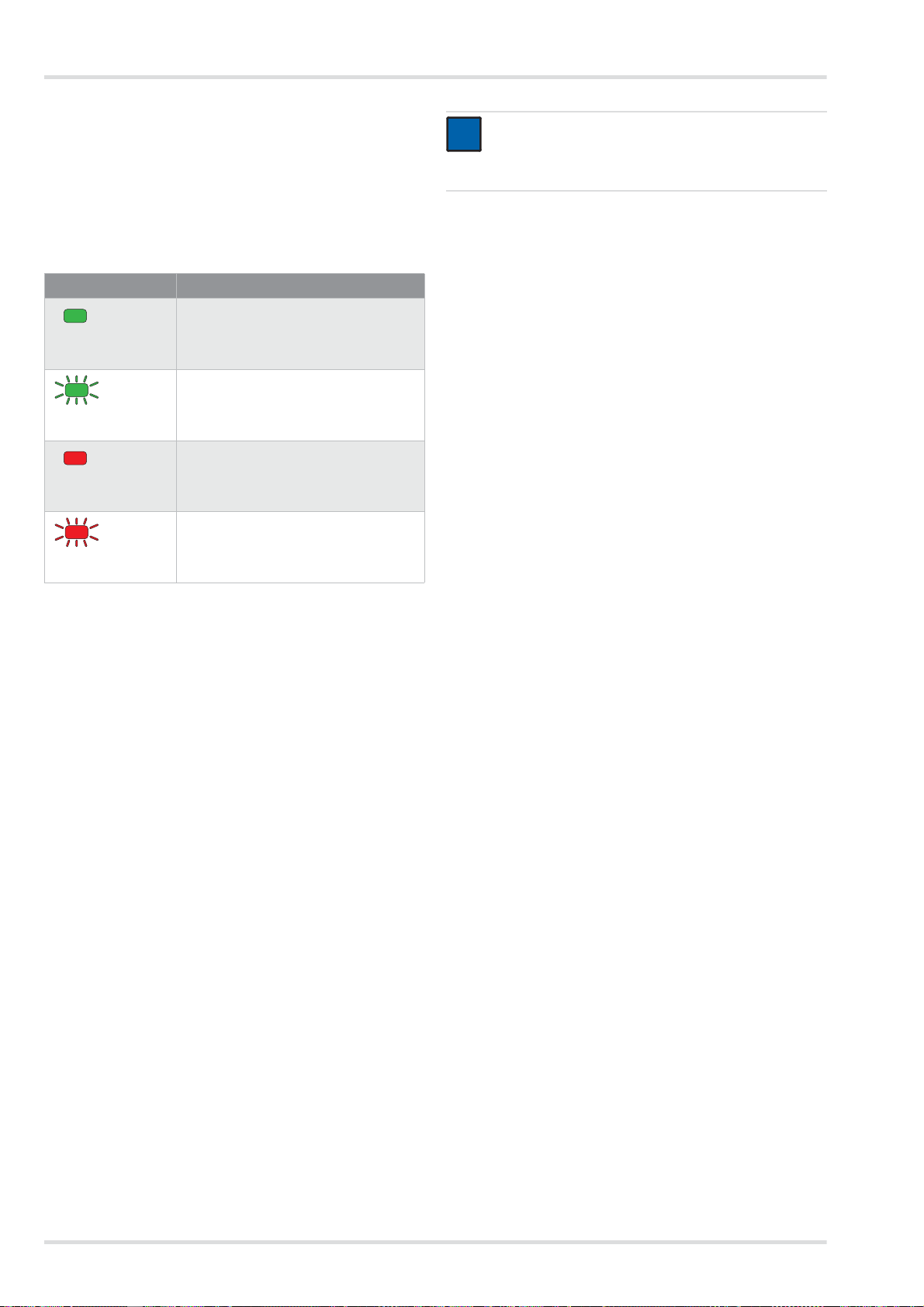
Description
2.2.6 Chargeurs
Chargeur standard
Ź Représentation sur la page dépliante (figure G)
1 LED de statut
2 Bloc d'alimentation
3 Logement de l'accu
Signification de la LED de statut
Affichage Signification
L'accu est inséré et est chargé complè-
tement (mode veille).
La LED de statut est
allumée en vert.
L'accu est inséré et est chargé.
La LED de statut cli-
gnote en vert.
L'accu n'est pas inséré.
La LED de statut est
allumée en rouge.
Défaut
La LED de statut cli-
gnote en rouge.
Lorsque l'accu est entièrement chargé, le chargeur commute
automatiquement en mode veille. En mo de ve ille, l'a ccu reste
toujours chargé complètement. Il ne passera pour autant pas
en surcharge ni ne sera endommagé.
2.3 Description du fonctionnement
REMARQUE
i
i
L'alarme vibratoire est émise en plus de l'alarme sonore. Selon l'épaisseur et le matériau du vêtement,
l'alarme vibratoire n'est pas perceptible le cas échéant.
L'unité de ventilation fournit toujours le même débit volumétrique préréglé.
Lorsque l'unité de ventilation ne peut plus fournir à brève
échéance le débit volumétrique préréglé (par ex. en raison
d'une saturation en hausse du filtre anti-particules), un avertissement ou une alarme est émis(e).
2.4 Domaine d'utilisation
Selon le type de filtre utilisé, l'appareil offre une protection
contre les particules, les gaz, les vapeurs ou des mélanges de
ces derniers éléments.
2.5 Restrictions posées au domaine
d'utilisation
L'appareil ne convient pas pour une utilisation :
z dans les zones à explosions (zones ex)
z pour des substances nocives avec des caractéristiques
d'alerte faibles (odeur, goût, irritation des yeux et des voies
respiratoires)
z pour des interventions dans des cuves, fosses, canaux non
aérés, etc.
2.6 Autorisations
L'appareil est homologué selon :
z EN 12941:2009-02
z EN 12942:2009-02
Le système filtrant à ventilation assistée est un appareil de protection respiratoire dépendant de l'air environnant.
Il filtre l'air ambiant et vous met ainsi à disposition de l'air respirable. Pour cela, l'appareil aspire en permanence l'air ambiant à travers le filtre. En fonction du type de filtre, les
substances nocives sont retenues dans le filtre. De cette manière, l'air ambiant est retraité et parvient ensuite dans le raccord respiratoire. Il est alors disponible comme air respiratoire.
Une surpression continue dans le raccord respiratoire agit
contre la pénétration d'air ambiant.
2.3.1 Dispositifs d'avertissement
Les défauts survenant lors de l'utilisation sont indiqués par des
dispositifs d'avertissement.
Les dispositifs d'avertissements sont entre autres les suivants :
z Alarme visuelle (affichage sur le panneau de commande)
z Alarme sonore
z Alarme par vibratoire
L'appareil satisfait en conséquence à la directive relative aux
équipements de protection individuelle 89/686/CEE.
Autres directives dans le cadre du marquage CE :
z Directive CEE (2004/108/CE)
z Directive R&TTE (1999/5/CE)
z Directive NSR (2006/95/CE)
z Directive RoHS (2011/65/UE)
2.7 Explication des marquages
d'identification et des symboles
2.7.1 Plaques signalétiques
Ź Représentation des plaques signalétiques à la page 4
Unité de ventilation : Figure H
Chargeur standard : Figure I
Accu : Figure J
1 Désignation du produit
2 Type de protection
3 Normes EN satisfaites
4 Symbole "Respecter la notice d'utilisation"
5 Symbole DEEE "Collecte sélective des déchets électriques
et électroniques"
28 Dräger X-plore 8000
Page 29
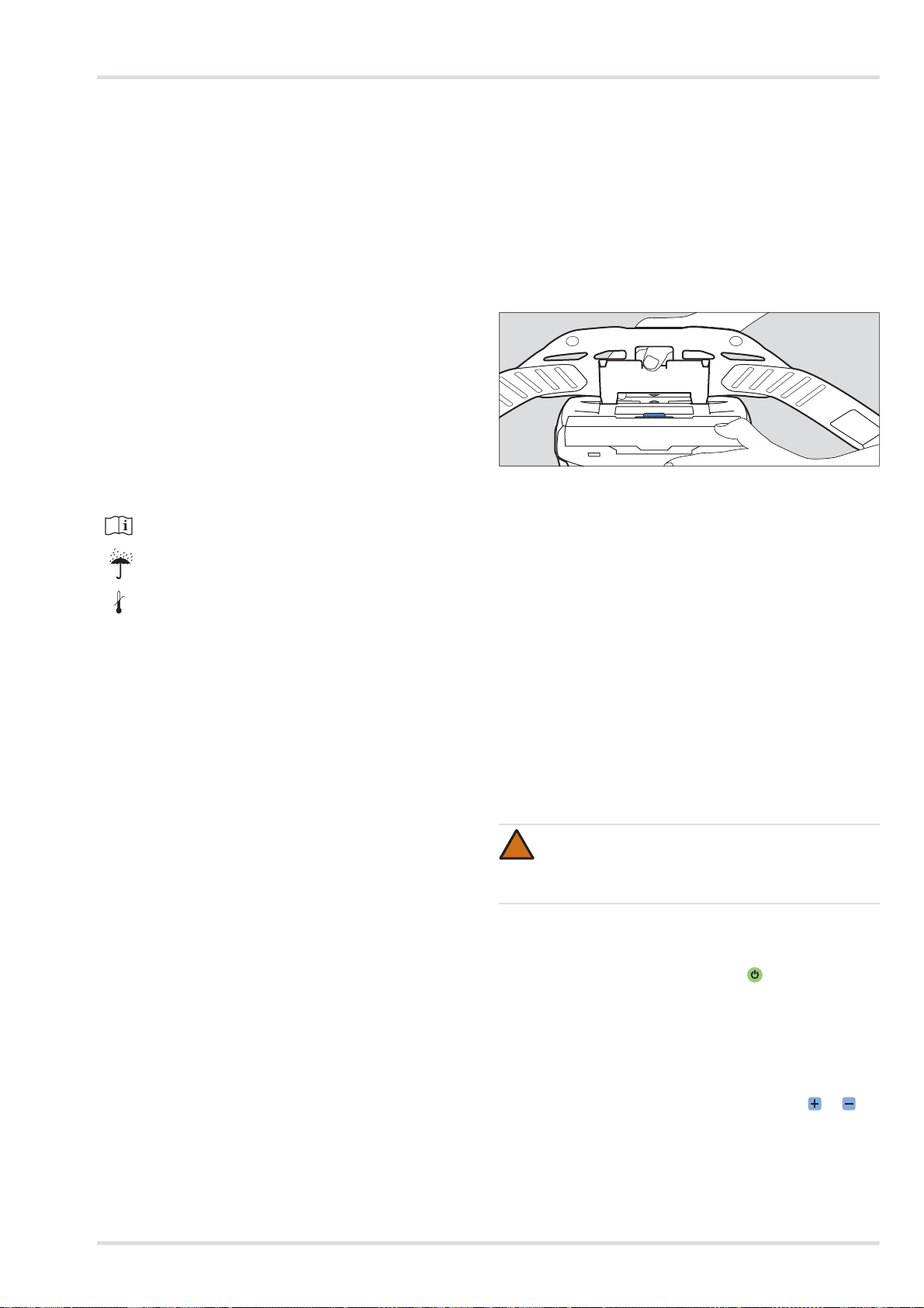
Utilisation
<95%
-20°C
+70°C
04733412.eps
6 Pays de production
7 Fabricant
8 Marquage CE
9 Code DataMatrix avec numéro de pièce et de fabrication
10 Numéro de fabrication
11 Référence de produit
12 Utilisation uniquement en intérieur, pas en extérieur
13 Température ambiante maximale
14 Données électriques
15 Affectation des connecteurs
16 Symbole de recyclage
17 Mise en garde
Information sur l'année de fabrication
L'année de production résulte de la 3e lettre du numéro de fa-
brication : F = 2014, G = néant, H = 2015, I = néant, J = 2016,
K = 2017 etc.
Exemple : numéro de fabrication ARFH-0054 : la troisième
lettre est F, donc année de fabrication 2014.
2.7.2 Emballage
Observer la notice d'utilisation
Humidité maximale de stockage
5. Monter le système de port (voir le chapitre 3.2.1 à la page
29).
6. Monter éventuellement les accessoires (voir le chapitre 3.5
à la page 30).
7. Mettre en place l'appareil voir le chapitre 3.2.2 à la page
29.
8. Raccorder le raccord respiratoire (voir le chapitre 3.2.3 à la
page 29)
9. Mettre en marche l'appareil voir le chapitre 3.2.4 à la page
29.
3.2.1 Montage du système de port
1. Monter la plaque de liaison du système de port sur le logement de l'unité de ventilation. Les marquages fléchés de la
plaque de liaison et du logement doivent correspondre.
2. Appuyer sur la plaque de li aison jusqu'à ce qu'elle s'enclenche de manière audible sur le logement.
Plage de la température de stockage
3 Utilisation
3.1 Conditions relatives à l'utilisation
z Les conditions ambiantes (en particulier le type et la
concentration des substances toxiques) doivent être
connues.
z Le taux d'oxygène dans l'air environnant ne doit pas des-
cendre en-dessous des valeurs limites suivantes :
{ au moins 17 % de volume d'oxygène dans tous les
pays européens sauf les Pays-Bas, la Belgique et la
Grande-Bretagne
{ au moins 19 % de volume d'oxygène aux Pays-Bas, en
Belgique, en Grande-Bretagne, en Australie et en Nouvelle-Zélande
{ au moins 19,5 % de volume d'oxygène aux États-Unis.
Dans les autres pays, observer la réglementation nationale.
3.2 Opérations préalables à l'utilisation
En dehors de la zone dangereuse, effectuer les activi tés suivantes :
1. Sélectionner les composants du système filtrant à ventilation assistée (filtre, raccord respiratoire) en fonction de la
classe de protection nécessaire et de la tâche (voir matrice
de configuration [Configuration Matrix] à la page 243).
2. Effectuer un contrôle visuel (voir le chapitre 5.3.1 à la page
32).
3. Vérifier l'état de charge de l'accu (voir le chapitre 5.3.3 à la
page 32).
4. Insérer le filtre (voir le chapitre 5.3.4 à la page 33).
3.2.2 Mise en place de l'appareil
1. Régler le ceinturon du système de port à la taille nécessaire.
2. Retourner le ce inturon et fermer la boucle. L'appareil se
trouve sur le dos de l'utilisateur.
3. Tendre le ceinturon et fixer les extrémités qui dépassent
avec les attaches du ceinturon.
3.2.3 Raccordement du raccord respiratoire
1. Raccorder le raccord à encliqueter du tuyau respiratoire
sur l'unité de ventilation.
2. Relier l'autre extrémité du tuyau respiratoire au raccord
respiratoire.
AVERTISSEMENT
!
Entrée d'air ambiant !
Avant utilisation, s'assurer que tous les composants
sont bien attachés les uns aux autres.
3.2.4 Mise en marche de l'appareil
1. Mettre en marche l'unité de ventil ation en appuyant (pen-
dant 2 secondes env.) sur la touche sur le panneau de
commande.
L'appareil effectue un autotest après la mise en marche.
2. Lorsque l'appareil ne foncti onne pas parfaitement ou que
des dispositifs d'avertissement se déclenchent, éliminer le
défaut (voir le chapitre 4 à la page 30).
3. Monter le raccord respiratoire (voir la notice d'utilisation du
raccord respiratoire correspondant).
4. Ajuster le débit volumétrique avec les touches et selon vos souhaits.
Dräger X-plore 8000 29
Page 30
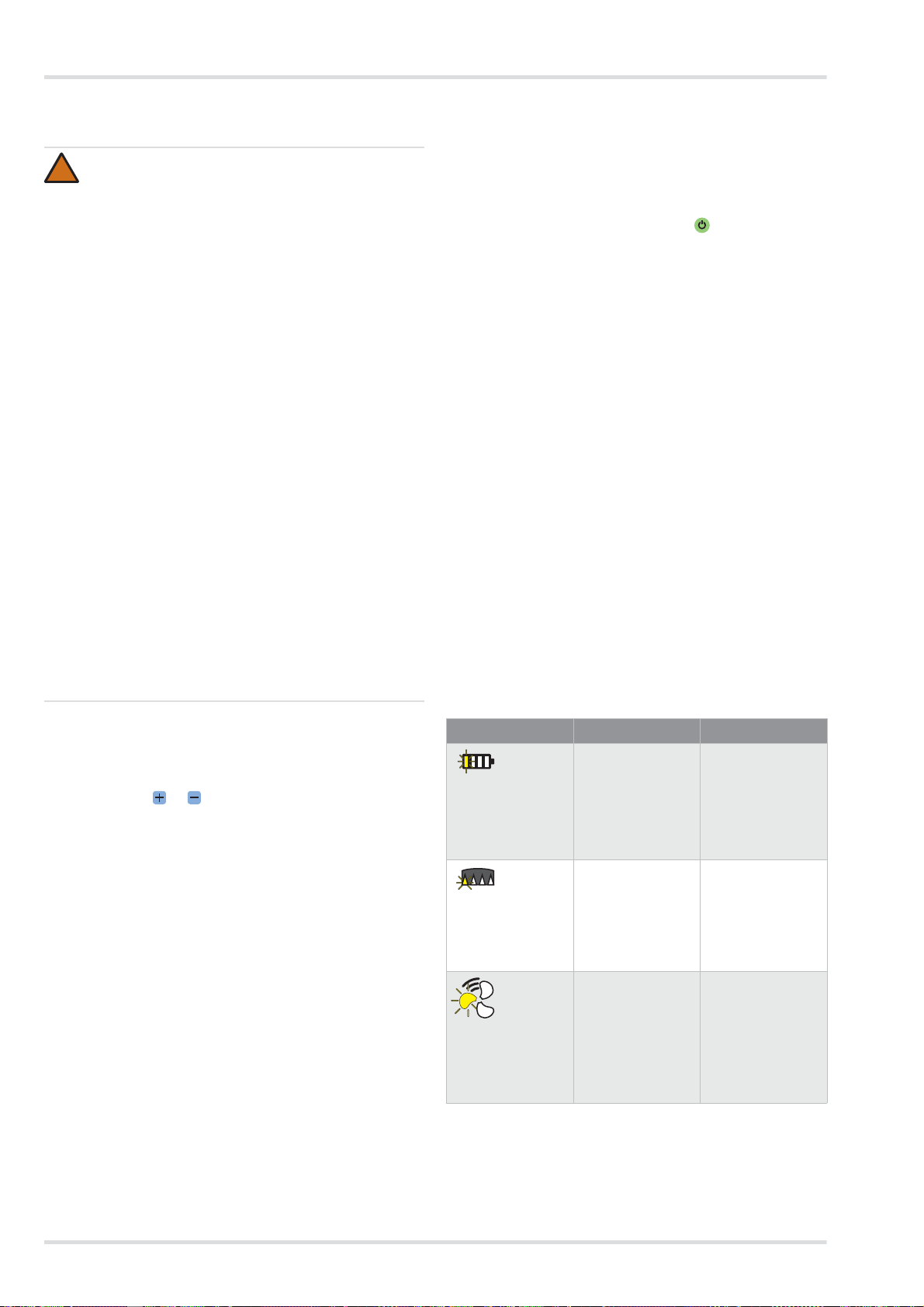
Élimination des pannes
!
3.3 Pendant l'utilisation
AVERTISSEMENT
Danger pour la santé !
Quitter immédiatement la zone dangereuse dans les
cas suivants :
z Alimentation d'air en baisse ou interrompue
(par ex. en raison d'une panne du ventilateur)
Avec le type de raccord respiratoire cagoule/
casque/visière de protection, une accumulation de
dioxyde de carbone ou un manque d'oxygène peut
vite survenir. En outre, un air ambiant nocif peut
pénétrer dans la cagoule.
z Développement d'odeur ou du goût dans le raccord
respiratoire (passage à travers le filtre). La capacité restante du filtre à gaz ou des composants du
filtre à gaz du filtre combiné est épuisée.
z Torpeur, vertige ou autres douleurs
z Endommagement de l'appareil
z Autres alarmes affichées (voir le chapitre 4 à la
page 30)
Les tuyaux respiratoires ou autres composants
masquent le risque d'accrochage. Cela peut amener
un endommagement de l'appareil et une interruption
de l'alimentation en air !
Lors de l'utilisation de l'appareil, procéder avec précaution.
3.4 Après l'utilisation
Effectuer les activités suivantes :
1. Quitter la zone dangereuse.
2. Déposer le raccord respiratoire (voir la n otice d'utilisation
du raccord respiratoire correspondant).
3. Mettre l'unité de ventilation hors service en appuyant (pen-
dant 2 secondes env.) sur la touche sur le panneau de
commande.
4. Ouvrir le ceinturon du système de port et retirer l'appareil.
5. Nettoyage et désinfection de l'appareil (voir le chapitre 5.2
à la page 32)
3.5 Opérations générales réservées à
l'utilisateur
3.5.1 Pose de la mousse de confort pour un ceinturon
standard
Relier la mousse de confort au ceinturon standard avec les
boutons à pression.
3.5.2 Montage de la rallonge du ceinturon le système de
port
Si nécessaire, monter la rallonge de ceinture sur la boucle d e
la sangle.
4 Élimination des pannes
Lors de l'utilisation du type de raccord respiratoire cagoule/casque/visière de protection, une dépression
peut survenir lors de l'inspiration en cas de travail difficile et de l'air non filtré peut pénétrer !
Afin de contrer ce phénomène, augmenter le débit volumétrique.
3.3.1 Régulation a posteriori du débit volumétrique
Si nécessaire (par ex. en cas d'effort corporel accru), réguler à
postériori le débit volumétrique pendant le fonctionnement
avec les touches et .
3.3.2 Avertissements et alarmes
Si une alerte est déclenchée, quitter sans délai la zone de travail compte tenu de la situation dangereuse possible.
Afin d'augmenter la durée d'utilisation lorsqu'une alerte survient, diminuer le débit volumétrique. (Uniquement possible
lorsque le niveau le plus faible n'est pas déjà sélectionné.) En
baissant le débit volumétrique, la durée de fonctionnement de
l'accu peut par ex. être prolongée.
Si une alarme est déclenchée, quitter la zone de travail immédiatement, sans délai.
Après déclenchement d'une alarme ou d'un avertissement, vérifier le fonctionnement de l'appareil (voir le chapitre 4 à la
page 30).
4.1 Avertissements
Le type d'avertissement est signalé de manière visuelle par un
clignotement jaune de l'affichage correspondant. De plus, un
signal d'avertissement sonore est déclenché et l'alarme vibratoire se déclenche.
Erreur Cause Solution
Un segment de
l'affichage de l'état
de charge de l'accu clignote en
jaune.
Un segment de
l'affichage de la capacité restante du
filtre à particules
clignote en jaune.
Un segment de
l'affichage du débit
volumétrique clignote en jaune.
La durée de fonctionnement restante de l'accu est
faible
(< 30 minutes).
La capacité restante du filtre à particules est faible
(< 20 %).
Défaut lors de la
mise en marche
(par ex. en raison
d'un tuyau ou filtre
manquant).
Charger rapidement l'accu ou le
remplacer par un
accu entièrement
chargé (voir le chapitre 5.3.3 à la
page 32).
Remplacer rapidement le filtre à particules ou le filtre
combiné (voir le
chapitre 5.3.4 à la
page 33).
Vérifier le fonctionnement de l'appareil et préparer
l'appareil de nouveau pour l'utilisation (voir le
chapitre 3.2 à la
page 29).
30 Dräger X-plore 8000
Page 31

Entretien
4.2 Alarmes
Le type d'alarme est signalé de manière visuelle par un clignotement rouge de l'affichage correspondant. De plus, un signal
d'alarme sonore est déclenché et l'alarme vibratoire se déclenche.
Erreur Cause Solution
Un segment de
l'affichage de l'état
de charge de l'accu clignote en
rouge.
Un segment de
l'affichage de la capacité restante du
filtre à particules
clignote en rouge.
Un segment de
l'affichage du débit
volumétrique clignote en rouge.
Un segment clignote en rouge.
Durée de fonctionnement restante
de l'accu presque
épuisée
(< 10 minutes)
Capacité restante
du filtre à particules presque
épuisée (< 10 %).
Alimentation en air
respirable incorrecte pendant le
fonctionnement
(par ex. en raison
d'un tuyau ou filtre
manquant).
Erreur système générale
Charger l'accu ou
le remplacer par un
accu entièrement
chargé (voir le chapitre 5.3.3 à la
page 32).
Remplacer le filtre
à particules ou le
filtre combiné (voir
le chapitre 5.3.4 à
la page 33).
Vérifier le fonctionnement de l'appareil et préparer
l'appareil de nouveau pour l'utilisation (voir le
chapitre 3.2 à la
page 29).
Faire vérifier l'appareil par Dräger
Service.
5 Entretien
5.1 Intervalles de maintenance
Travaux à effectuer
Annuellement
Avant utilisation
Après utilisation
Nettoyer et désinfecter l'appareil
Effectuer le contrôle visuel X
Vérifier l'état de charge de
l'accu
Changer l'accu X
Charger l'accu X
Remplacer le filtre X
Contrôler le débit volumé-
trique et des dispositifs
d'avertissement
Remplacer le joint torique sur
le raccord à encliqueter ou le
raccord à baïonnette des
tuyaux
1) Appareils sous emballage étanche, sinon tous les 6 mois
X
X
tous les 2 ans
1)
X
1)
X
X X
Si nécessaire
X
Dräger X-plore 8000 31
Page 32

Entretien
!
5.2 Nettoyage et désinfection
ATTENTION
Endommagement possible des éléments !
Pour le nettoyage et la désinfection, utiliser uniquement
les procédés décrits et les produits de nettoyage et de
désinfection mentionnés. Les autres produits et procédés, dosages et temps d'action peuvent endommager
les éléments.
Danger pour la santé !
Le contact direct de la peau ou des yeux avec les produits non dilués est dangereux. Lors des travaux avec
ces produits, porter des lunettes et des gants de protection.
5.2.1 Nettoyage et désinfection de l'appareil
1. Démonter l'appareil :
a. séparer le tuyau respiratoire, le raccord respiratoire et
l'unité de ventilation.
b. Séparer le système de port de l'unité de ventilation.
c. Si existants, démonter les accessoires (par ex. gaines
de tuyau et d'appareil).
d. Démonter le couvercle de protection contre les projec-
tions et le filtre (voir le chapitre 5.3.4 à la page 33).
2. Nettoyer le raccord respiratoire selon la notice d'utilisation
correspondante.
3. Nettoyer le tuyau respiratoire et le système de port :
a. Nettoyer toutes les pièces avec de l'eau tiè de en ajou-
tant du nettoyant Sekusept
doux (température : max. 30 °C, concentration selon le
degré de salissure : 0,5 - 1 %).
b. Rincer soigneusement toutes les pièces à l'e au du ro-
binet.
c. Préparer un bain de désinfection constitué d'eau et
d'Incidin
tration : 1,5 %).
d. Placer toutes les pièces qui doivent être désinfectées
dans le bain désinfectant (durée : 15 minutes).
e. Rincer soigneusement toutes les pièces à l'e au du ro-
binet.
f. Laisser toutes les pièces sécher à l'air ou dans l'ar-
moire de séchage (température : max. 60 °C). Protéger
contre l'ensoleillement direct.
4. Nettoyer et désinfecter l'unité de ventilation et le couvercle
de protection contre les projections avec des lingettes de
désinfection Incides
En cas d'encrassement important, l'unité de ventilation peut
être rincée sous l'eau courante de la manière suivante.
1. S'assurer que l'accu reste inséré. De l'eau ne doit pas pénétrer dans le logement de l'accu.
2. Fermer l'ouverture d'aspiration et le raccord de tuyau avec
des bouchons filetés (disponibles comme accessoires).
®
Rapid2) (température : max. 30 °C, concen-
®N 1)
®
Cleaner1) et un chiffon
.
5.3 Travaux de maintenance
5.3.1 Réalisation du contrôle visuel
Vérifier soigneusement toutes les pièces et remplacer le cas
échéant les pièces. Vérifier en particulier que la zone d'étanchéité des filtres sur l'unité de ventilation n'est pas endommagée (par ex. rayures) ni encrassée.
5.3.2 Vérification de l'état de charge de l'accu
1. Appuyer sur l'accu sur la touche afin d'afficher l'état de
charge.
2. Relever l'affichage d'état de charge.
3. Lorsque l'état de charge ne suffit pas à la durée d'utilisation
prévue :
remplacer l'accu ou le charger (voir le chapitre 5.3.3 à la
page 32).
5.3.3 Remplacement ou charge de l'accu
ATTENTION
!
Endommagement de l'accu en raison d'un court-circuit !
Déposer l'accu toujours de manière à ce que les
contacts ne touchent pas le métal.
Déposer l'accu :
1. Relever éventuellement le système de port.
2. Appuyer sur la touche de verrouillage de l'accu. Veiller à ce
que l'accu ne tombe pas.
3. Retirer l'accu.
Insérer l'accu :
1. Relever éventuellement le système de port.
2. Insérer l'accu d'abord en biais dans le logement puis le
rabattre à l'intérieur de sorte qu'il s'enclenche audiblement.
Charger l'accu :
REMARQUE
i
i
Toujours séparer le chargeur de l'alimentation en courant lorsqu'il n'est pas utilisé.
1. Vérifier la tension du secteur correcte de l'ali mentation en
courant. La tension de fonctionnement du bloc d'alimentation doit correspondre à la tension du secteur.
2. Relier le chargeur au bloc d'alimentation.
3. Raccorder le bloc d'alimentation à l'alimentation en courant.
4. Insérer l'accu d'abord en biais dans le chargeur puis le
rabattre à l'intérieur de sorte qu'il s'enclenche audiblement.
5. Attendre la fin de la charge.
6. Lorsque l'accu est complètement chargé, appuyer sur la
touche de verrouillage de l'accu et retirer l'accu.
7. Séparer le bloc d'alimentation de l'alimentation en courant
et le chargeur du bloc d'alimentation.
1) Sekusept® et Incides® sont des marques déposées par Ecolab
Deutschland GmbH.
®
2) Incidin
32 Dräger X-plore 8000
est une marque déposée d'Ecolab USA Inc.
Page 33

Transport
!
!
i
i
02633412.eps
A
02733412.eps
B
B
02933412.eps
02833412.eps
A
5.3.4 Remplacement du filtre
AVERTISSEMENT
Sans filtre aucun effet protecteur !
Ne pas utiliser l'appareil sans filtre.
ATTENTION
Endommagement de l'unité de ventilation en raison de
la pénétration de particules !
Lors du retrait du filtre, veiller à ce qu'aucune particule
ne parvienne dans l'appareil via l'ouverture d'aspiration.
REMARQUE
Selon le type de filtre utilisé, le déroulement est différent pour le remplacement du filtre.
Filtre à particules
Retirer le filtre :
1. Appuyer sur la touche de verrouillage du filtre.
2. Déplier vers l'extérieur le filtre avec le couvercle de protection contre les projections (figure A).
3. Retirer le filtre usagé (figure B).
Insérer le filtre :
1. Vérifier si le join t en caoutchouc sur le filtre n'est pas endommagé.
2. Insérer un nouveau filtre dans le couvercle de pro tection
contre les projections.
3. Insérer le filtre avec l e couvercle de protection contre les
projections en biais dans l'unité de ventilation.
4. Replier vers l'intérieur le filtre avec le couvercle de protection contre les projections de sorte qu'il s'enclenche de manière perceptible.
Filtre à gaz et combiné
Retirer le filtre :
b. Déplier vers l'extérieur le couvercle de protection
contre les projections (figure B).
Insérer le filtre :
1. Vérifier si le join t en caoutchouc sur le filtre n'est pas endommagé.
2. Placer le couvercle de protection contre les projections
avec le bord inférieur en biais sur le filtre.
3. Appuyer sur le couvercle de protection contre les projections de sorte qu'il s'enclenche de manière perceptible.
4. Insérer le filtre avec l e couvercle de protection contre les
projections en biais dans l'unité de ventilation.
5. Replier vers l'intérieur le filtre avec le couvercle de protection contre les projections de sorte qu'il s'enclenche de manière perceptible.
5.3.5 Contrôle du débit volumétrique et des dispositifs
d'avertissement
1. S'assurer qu'un filtre est inséré (voir le chapitre 5.3.4 à la
page 33).
2. Raccorder le raccord à encliqueter du tuyau respiratoire
sur l'unité de ventilation.
3. Mettre en marche l'unité de ventilation en appuyant sur la
touche sur le panneau de commande.
L'appareil effectue un autotest après la mise en marche.
Lorsque l'appareil ne fonctionne pas parfaitement ou que
des dispositifs d'avertissement se déclenchent, éliminer le
défaut (voir le chapitre 4 à la page 30).
4. Boucher l'extrémité ouverte du tuyau respiratoire avec la
paume de la main.
L'unité de ventilation commence à fonctionner de manière
plus intensive après 5 secondes env. Après 20 secondes
env., une alarme est déclenchée.
Lorsque le ventilateur ne modifie pas le régime et qu'aucune alarme ne se déclenche, faire contrôler l'unité de ventilation.
5. Si souhaité, mettre l'unité de ventilation de nouveau hors
service en appuyant à nouveau sur la touche sur le panneau de commande.
5.3.6 Remplacer le joint torique sur le raccord à
encliqueter ou le raccord à baïonnette des tuyaux
1. Faire sortir l'ancien joint toriq ue à l'aide de l'outil de retrait
sur l'encoche.
2. Insérer le nouveau joint torique dans la rainure prévue.
6Transport
Transport dans l'emballage d'origine ou dans le boîtier de
transport disponible en option.
7 Stockage
Stocker l'ensemble du système :
z Démonter le filtre et l'accu.
z Conserver les composants dans un contenant ou une ar-
moire au sec et à l'abri des poussières et les protéger des
rayonnements solaires et thermiques directs.
Stocker les accus :
1. Appuyer sur la touche de verrouillage du filtre.
2. Déplier vers l'extérieur le filtre avec le couvercle de protection contre les projections (figure A).
3. Démonter le couvercle de protection contre les projections :
a. Appuyer au milieu sur l e bord supérieur du couvercle
de protection contre les projections de sorte qu'il sorte.
Dräger X-plore 8000 33
z Les accus fortement déchargés peuvent être endomma-
gés en cas de stockage prolongé. Avant de les stocker,
charger les accus de 50 à 70 %.
z En cas de stockage de plus de 6 mois, recharger de temps
en temps les accus.
Page 34

Élimination
z Ne pas stocker les accus pendant longtemps en dehors de
la plage de température recommandée. Cela peut réduire
la capacité restante et le nombre des cycles de charge
possibles.
8 Élimination
Ce produit ne doit pas être éliminé comme déchet ménager. C'est pourquoi, il est caractérisé par le symbole
suivant.
Dräger reprend gratuitement ce produit. Pour de plus
amples informations, veuillez consulter les filiales locales et Dräger.
Les batteries et accus ne doivent pas être éliminés
comme déchets ménagers. C'est pourquoi, ils sont caractérisés par le symbole suivant. Remettre les batteries et accus aux points de collecte pour piles et
batteries usagées conformément aux prescriptions en
vigueur.
9 Caractéristiques techniques
Ensemble du système
Débit volumétrique cagoule/
casque/visière de protection respiratoire :
Débit volumétrique masque intégral/demi-masque :
Durée d'utilisation nominal : 4 heures
Température de travail :
Humidité de l'air de travail/
stockage :
Température de stockage :
Niveau de bruits : env. 64 dB(A)
Type de protection : IP 65
1) Pour le chargeur et les accus se conférer aux indications séparées
1)
dans ce chapitre.
Pour les autres composants voir la notice d'utilisation correspondante.
1)
1)
Accus
Température de travail : de -10 °C à 60 °C
Humidité de l'air de travail/
stockage :
Température de stockage : de -20 °C à 50 °C
Température de charge : de 0 °C à 50 °C
Accu standard
Durée de charge : <4 heures
Durée de fonctionnement après
une charge :
Tension nominale : 10,8 V
170/190/210 l/min
115/130/145 l/min
avec accu standard
8 heures
avec accu longue durée
de -10 °C à 60 °C
95 % d'humidité rela-
tive
de -20 °C à 60 °C
95 % d'humidité relative
env. 4 heures
1)
Capacité nominale : 3,35 Ah
Puissance débitée : 36 Wh
Accu longue durée
Durée de charge : <4 heures
Durée de fonctionnement après
une charge :
Tension nominale : 10,8 V
Capacité nominale : 6,70 Ah
Puissance débitée : 72 Wh
1) Varie selon le débit volumétrique réglé et le type de raccord respiratoire et de filtre utilisé
env. 8 heures
1)
Chargeur
Tension d'entrée : 15 V
Intensité d'entrée : 4A
Tension de sortie : 9 - 12,6 V
Intensité de sortie : 4A
Type de protection : IP 30
Température de travail : de 0 °C à 50 °C
Humidité de l'air de travail/
stockage :
Température de stockage : de -20 °C à 50 °C
95 % d'humidité relative
10 Liste de commande
Composants
1)
Pos.
Désignation et description Code
1 Dräger X-plore 8500 (IP) R59500
2 Accu standard Dräger X-plore 8000 R59565
3 Accu longue durée Dräger X-plore 8000 R59585
4 Ceinturon standard Dräger X-plore 8000 R59700
5 Ceinturon décontaminable Dräger X-
plore 8000
6 Tuyau standard Dräger X-plore 8000
(pour masque complet/demi-masque)
7 Tuyau standard Dräger X-plore 8000
(pour cagoules)
8 Tuyau standard Dräger X-plore 8000
(pour casques et visières)
9 Tuyau flexible Dräger X-plore 8000
(pour masque complet/demi-masque)
10 Tuyau flexible Dräger X-plore 8000
(pour cagoules)
11 Tuyau flexible Dräger X-plore 8000
(pour casques et visières de protection)
12 Filtre P R S L Dräger X-plore 8000 6739535
13 Filtre A2 Dräger X-plore 8000 6739580
14 Filtre A2 P R SL Dräger X-plore 8000 6739545
R59710
R59630
R59620
R59640
R59610
R59600
R59650
34 Dräger X-plore 8000
Page 35

Liste de commande
1)
Pos.
1) Voir matrice de configuration (Configuration Matrix) à la page 243.
Désignation et description Code
15 Filtre A1B1E1K1 Hg P R SL Dräger X-
plore 8000
16 Cagoule standard, court (S/M) Dräger
X-plore 8000
17 Cagoule standard, court (L/XL) Dräger
X-plore 8000
18 Cagoule standard, long (S/M) Dräger X-
plore 8000
19 Cagoule standard, long (L/XL) Dräger X-
plore 8000
20 Cagoule premium, court (S/M) Dräger
X-plore 8000
21 Cagoule premium, court (L/XL) Dräger
X-plore 8000
22 Cagoule premium, long (S/M) Dräger X-
plore 8000
23 Cagoule premium, long (L/XL) Dräger X-
plore 8000
24 Casque Dräger X-plore 8000 avec vi-
sière, noir
25 Casque Dräger X-plore 8000 avec vi-
sière, blanc
26 Visière de protection Dräger X-plore
8000
27 Dräger X-plore 6300 EPDM/PMMA R55800
28 Dräger X-plore 6530 EPDM/PC R55795
29 Dräger X-plore 6570 SI/PC R55790
30 Dräger X-plore 4740 SI S/M R55875
31 Dräger X-plore 4740 SI M/L R55874
32 Dräger FPS 7000 EPDM-S1-PC-CR R56502
33 Dräger FPS 7000 EPDM-M2-PC-CR R56310
34 Dräger FPS 7000 EPDM-L2-PC-CR R56503
35 Dräger X-plore 8000 chargeur standard R59580
6739555
R59800
R59810
R59820
R59830
R59840
R59850
R59860
R59870
R58325
R59910
R59900
Pièces de rechange
Pos. Désignation et description Code
42 Couvercle de protection contre les pro-
jections Dräger X-plore 8000
43 Fixation pour cein R59705
44 Boucle enfichable, jeu R59715
45 Joint torique pour raccord à encliqueter
X-plore 8000 cagoule et unité de ventilation
46 Joint torique pour raccord à baïonnette
X-plore 8000 casque et visière de protection
47 Outil de retrait des joints toriques R21402
6739725
R59631
R59632
Produits de nettoyage et de désinfection
Pos. Désignation et description Code
48
Sekusept® Cleaner, 4 x 2 L
49
Incidin® Rapid, 6 L
autres emballages sur demande
50
Lingettes de désinfection Incides®N,
6 boîtes à 90 lingettes
7904071
R61880
6570001
Accessoires
1)
Pos.
1) Voir matrice de configuration (Configuration Matrix) à la page 243.
Dräger X-plore 8000 35
Désignation et description Code
36 Bouchons de fermeture Dräger X-plore
8000 (pour raccord de tuyau de l'unité
de ventilation)
37 Bouchons de fermeture Dräger X-plore
8000 (pour ouverture d'aspiration de
l'unité de ventilation)
38 Mousse de confort Dräger X-plore 8000 R59730
39 Rallonge pour ceinturon standard
X-plore 8000 ceinture standard,35 cm
40 Rallonge pour ceinturon décontami-
nable X-plore 8000, 35 cm
41 Boîte de rangement Dräger X-plore
8000
R59563
R59564
R59750
R59760
R59690
Page 36

Índice
Índice
1 Para su seguridad . . . . . . . . . . . . . . . . . . . . . . . .37
1.1 Indicaciones generales de seguridad . . . . . . . . . . .37
1.2 Significado de las señales de advertencia . . . . . . .37
2 Descripción . . . . . . . . . . . . . . . . . . . . . . . . . . . . . .37
2.1 Visión general del sistema . . . . . . . . . . . . . . . . . . .37
2.2 Componentes . . . . . . . . . . . . . . . . . . . . . . . . . . . . . 37
2.2.1 Unidad filtrante . . . . . . . . . . . . . . . . . . . . . . . . . . . .3 7
2.2.2 Filtro y conexiones respiratorias . . . . . . . . . . . . . . .38
2.2.3 Tubos respiratorios . . . . . . . . . . . . . . . . . . . . . . . . .38
2.2.4 Sistemas de transporte . . . . . . . . . . . . . . . . . . . . . .38
2.2.5 Baterías . . . . . . . . . . . . . . . . . . . . . . . . . . . . . . . . .38
2.2.6 Cargadores . . . . . . . . . . . . . . . . . . . . . . . . . . . . . . .39
2.3 Descripción . . . . . . . . . . . . . . . . . . . . . . . . . . . . . . .39
2.3.1 Sistemas de alarma . . . . . . . . . . . . . . . . . . . . . . . .39
2.4 Uso previsto . . . . . . . . . . . . . . . . . . . . . . . . . . . . . .39
2.5 Restricciones del uso previsto . . . . . . . . . . . . . . . .39
2.6 Homologaciones . . . . . . . . . . . . . . . . . . . . . . . . . . .39
2.7 Explicación de los símbolos y marca identificativa
típica . . . . . . . . . . . . . . . . . . . . . . . . . . . . . . . . . . . .39
2.7.1 Placas de características . . . . . . . . . . . . . . . . . . . .39
2.7.2 Embalaje . . . . . . . . . . . . . . . . . . . . . . . . . . . . . . . . .40
3 Uso . . . . . . . . . . . . . . . . . . . . . . . . . . . . . . . . . . . . .40
3.1 Condiciones para el uso . . . . . . . . . . . . . . . . . . . . .40
3.2 Preparativos para el uso . . . . . . . . . . . . . . . . . . . . .40
3.2.1 Montar el sistema de transporte . . . . . . . . . . . . . . .40
3.2.2 Colocar el equipo . . . . . . . . . . . . . . . . . . . . . . . . . .40
3.2.3 Conectar la conexión respiratoria . . . . . . . . . . . . . .40
3.2.4 Encender el equipo . . . . . . . . . . . . . . . . . . . . . . . . .4 0
3.3 Durante el uso . . . . . . . . . . . . . . . . . . . . . . . . . . . .41
3.3.1 Volver a regular el caudal volumétrico . . . . . . . . . .41
3.3.2 Avisos y alarmas . . . . . . . . . . . . . . . . . . . . . . . . . .41
3.4 Después del uso . . . . . . . . . . . . . . . . . . . . . . . . . . .41
3.5 Tareas generales del usuario . . . . . . . . . . . . . . . . .41
3.5.1 Colocar el acolchado para el cinturón estándar . . . 41
3.5.2 Colocar la prolongación del cinturón en el sistema de
transporte . . . . . . . . . . . . . . . . . . . . . . . . . . . . . . . .41
4 Solución de averías . . . . . . . . . . . . . . . . . . . . . . . 41
4.1 Avisos . . . . . . . . . . . . . . . . . . . . . . . . . . . . . . . . . . .41
4.2 Alarmas . . . . . . . . . . . . . . . . . . . . . . . . . . . . . . . . .42
5 Mantenimiento . . . . . . . . . . . . . . . . . . . . . . . . . . .42
5.1 Intervalos de mantenimiento . . . . . . . . . . . . . . . . .42
5.2 Limpieza y desinfección . . . . . . . . . . . . . . . . . . . . .43
5.2.1 Limpiar y desinfectar el equipo . . . . . . . . . . . . . . . .4 3
5.3 Trabajos de mantenimiento . . . . . . . . . . . . . . . . . .43
5.3.1 Realizar una inspección visual . . . . . . . . . . . . . . . .43
5.3.2 Comprobar el estado de carga de la batería . . . . .43
5.3.3 Cambiar o cargar la batería . . . . . . . . . . . . . . . . . .43
5.3.4 Cambiar el filtro . . . . . . . . . . . . . . . . . . . . . . . . . . .44
5.3.5 Comprobar el caudal volumétrico y los sistemas de
alarma . . . . . . . . . . . . . . . . . . . . . . . . . . . . . . . . . . .44
5.3.6 Cambiar la junta tórica en la conexión enchufable
o de bayoneta de los tubos . . . . . . . . . . . . . . . . . .44
6 Transporte . . . . . . . . . . . . . . . . . . . . . . . . . . . . . . .44
7 Almacenamiento . . . . . . . . . . . . . . . . . . . . . . . . . .44
8 Eliminación de residuos . . . . . . . . . . . . . . . . . . .45
9 Características técnicas . . . . . . . . . . . . . . . . . . . .45
10 Lista de referencias . . . . . . . . . . . . . . . . . . . . . . .46
36 Dräger X-plore® 8000
Page 37

Para su seguridad
!
!
i
i
1 Para su seguridad
1.1 Indicaciones generales de seguridad
z Leer atentamente estas instrucciones de uso y las instruc-
ciones de uso de los componentes correspondientes antes
de su uso.
z Observar detenidamente las instrucciones de uso. El usua-
rio debe comprender íntegramente y cumplir estrictamente
las instrucciones. El producto debe utilizarse exclusivamente según su uso previsto.
z No eliminar las instrucciones de uso. Garantizar su conser-
vación y su uso correcto por parte de los usuarios.
z Solo personal especializado y formado debe utilizar este
producto.
z Observar las directrices locales y nacionales aplicables a
este producto.
z Solo personal especializado y formado debe comprobar,
reparar y mantener el producto.
z Usar sólo componentes y accesorios originales de Dräger.
De lo contrario, el funcionamiento correcto del producto
podría verse mermado.
z No utilizar productos incompletos ni defectuosos. No reali-
zar modificaciones en el producto.
z Informar a Dräger si se produjeran fallos o averías en el
producto o en componentes del mismo.
Ź Representación de la visión general del sistema en la pá-
gina desplegable (fig. A)
En un equipo completo se encuentran:
1 Tubo respiratorio
2 Conexión respiratoria (ejemplo con casco)
3 Sistema de transporte
4 Unidad filtrante con filtro y batería
En caso necesario, componentes accesorios (sin ilustración)
NOTA
i
i
Para una visión general de las combinaciones de dispositivos y de las correspondientes clases de protección, véase la matriz de configuración (Configuration
Matrix) en la página 243.
Las cifras en la línea superior de la matriz de configuración se corresponden con las posiciones de la lista
de referencias.
En este caso, los componentes enumerados están
destinados a la utilización con la unidad filtrante X-plore 8500 (pos. 1 de la lista de referencias) y las baterías
(pos. 2 y 3).
Ponerse en contacto con Dräger en caso de dudas sobre la configuración del equipo.
1.2 Significado de las señales de advertencia
Las siguientes señales de advertencia se utilizan en este documento para identificar y resaltar los textos de advertencia
que requieren mayor atención por parte del usuario. El significado de las señales de advertencia se define a continuación:
ADVERTENCIA
Advertencia de una situación potencialmente peligrosa.
En caso de no evitarse, pueden producirse lesiones
graves e incluso letales.
ATENCIÓN
Advertencia de una situación potencialmente peligrosa. En caso de no evitarse, pueden producirse lesiones o daños en el producto o en el medio ambiente.
Puede utilizarse también para advertir acerca de un
uso incorrecto.
NOTA
Información adicional sobre el uso del producto.
2 Descripción
2.1 Visión general del sistema
Dependiendo de los campos de aplicación y la clase de protección requerida, el equipo filtrante motorizado Dräger
®
X-plore
ponentes. En este caso, tener especialmente en cuenta los límites de uso de los filtros (véanse las instrucciones de uso de
los filtros).
80001) puede estar compuesto por diferentes com-
2.2 Componentes
2.2.1 Unidad filtrante
La unidad filtrante es el componente central del equipo.
Características del equipo:
z Panel de mandos con indicación del estado actual del sis-
tema
z Supervisión electrónica de las funciones del equipo
{ Caudal volumétrico
{ Capacidad restante del filtro de partículas
{ Estado de carga de la batería
{ Reconocimiento de tubos o filtros utilizables en el equi-
po
z Reconocimiento automático del tipo de conexión respirato-
ria utilizada (mascara/mascarilla o capucha/casco/visor de
protección) y adaptación automática del rango de caudal
volumétrico
z Caudal volumétrico con tres niveles seleccionables
z Reconocimiento óptico del tipo de filtro mediante señaliza-
ción con colores (punto de color en el filtro)
Ź Representación del lado delantero de la unidad filtrante en
la página desplegable (fig. B)
1 Conexión de tubo
2 Panel de mandos
3 Orificio de aspiración
4 Tapa de protección contra salpicaduras
5 Filtro (no incluido en la unidad filtrante)
6 Tecla de bloqueo del filtro
1) X-plore® es una marca registrada propiedad de Dräger.
Dräger X-plore 8000 37
Page 38

Descripción
i
i
Ź Representación del lado trasero de la unidad filtrante en la
página desplegable (fig. B)
1 Alojamiento del sistema de transporte
2 Placa de características
3 Sistema de transporte-Tecla de bloqueo
4 Tec la de bloqueo de la batería
5 Batería (no incluida en la unidad filtrante)
Panel de mandos
Ź Representación en la página desplegable (fig. D)
1 Indicador de carga de la batería
2 Indicador de la capacidad restante del filtro de partículas
3 Tecla on/off
4 Indicador del caudal volumétrico
5 Reducir el caudal volumétrico
6 Aumentar el caudal volumétrico
Relevancia de los indicadores en el panel de mandos
Indicación Significado
Estado de carga dependiendo del número de segmentos mostrados:
Segmentos iluminados
en verde.
> 75 % (4 segmentos)
> 50 % (3 segmentos)
> 25 % (2 segmentos)
< 25 % (1 segmento)
Capacidad restante del filtro de partícu-
1)
las
Segmentos ilumina-
dependiendo del número de seg-
mentos mostrados:
dos en verde.
> 75 % (4 segmentos)
> 50 % (3 segmentos)
> 25 % (2 segmentos)
< 25 % (1 segmento)
Intensidad del caudal volumétrico dependiendo del número de segmentos
mostrados:
Segmentos iluminados en verde.
Caudal volumétrico elevado
(3 segmentos)
Caudal volumétrico medio
(2 segmentos)
Caudal volumétrico bajo (1 segmento)
1) No se puede mostrar la capacidad restante del filtro de gas o de
los componentes del filtro de gas del filtro combinado.
NOTA
Los avisos o alarmas se muestran mediante diodos
LED parpadeantes en amarillo o rojo. Para conocer el
significado de las indicaciones en caso de fallo, véase
el capítulo 4 en la página 41.
2.2.2 Filtro y conexiones respiratorias
2.2.3 Tubos respiratorios
Los siguientes tubos respiratorios están disponibles:
z Tubo estándar
z Tubo flexible para aumentar la comodidad
Los dos tubos respiratorios están disponibles para los siguientes tipos de conexión respiratoria:
z Conexión acoplable (capucha)
z Conexión de bayoneta (casco y visor de protección)
z Conexión de rosca (máscara/mascarilla)
2.2.4 Sistemas de transporte
Ź Representación en la página desplegable (fig. E)
1 Placa de conexión
2Cinturón
3 Clips de cierre del cinturón
4 Hebilla
Se pueden seleccionar los sistemas de transporte siguientes:
z Cinturón estándar
El cinturón textil estándar dispone de corchetes para la fijación de un acolchado opcional.
z Cinturón descontaminable:
El cinturón de plástico descontaminable dispone de un cinturón lisa y está especialmente diseñada para la descontaminación.
2.2.5 Baterías
Ź Representación en la página desplegable (fig. F)
1 Tecla de bloqueo de la batería
2 Indicador de carga de la batería
3 Tecla para mostrar el estado de carga
4 Placa de características
Las baterías de iones de -litio- están especialmente equipadas
para la utilización con el equipo filtrante motorizado. Junto a la
batería estándar hay una batería de larga duración con un
tiempo de funcionamiento más elevado.
El indicador de carga de la batería muestra el estado durante
la carga con el cargador estándar o al pulsar una tecla. Durante la carga, los segmentos del indicador de carga de la batería
parpadean.
El indicador de carga de la batería se corresponde con el del
panel de mandos de la unidad filtrante (véase el capítulo 2.2.1
en la página 37).
Las baterías no alcanzan su capacidad máxima hasta después de 5 ciclos de carga- y descarga. El tiempo de carga es
normalmente de 3 horas.
En caso de una descarga fuerte, la batería se precarga, por lo
que el tiempo de carga se puede prolongar hasta por 4 horas.
Durante este tiempo, el indicador de carga de la batería no está activo.
El filtro y las conexiones respiratorias están descritas en instrucciones de uso independientes.
Para descartar el deterioro o la explosión de la batería, el proceso de carga se realiza solamente en el rango de temperatura de 0 a 50 °C. Si se sale de este rango de temperatura, el
proceso de carga se interrumpe automáticamente y se continúa tras volver a dicho rango.
38 Dräger X-plore 8000
Page 39

Descripción
2.2.6 Cargadores
Cargador estándar
Ź Representación en la página desplegable (fig. G)
1 LED-de estado
2 Fuente de alimentación
3 Compartimiento de batería
Significado del LED de estado
Indicación Significado
La batería está insertada y completa-
mente cargada (modo standby)
El LED de estado
se ilumina en ver-
de.
La batería está insertada y cargando.
El LED de estado
parpadea en verde.
La batería no está insertada.
El LED de estado
se ilumina en rojo.
Fallo
NOTA
i
i
La alarma vibratoria se emite de manera adicional junto con la alarma acústica. Dependiendo del espesor y
del material de la ropa, la alarma vibratoria podría no
ser perceptible.
La unidad filtrante suministra siempre el mismo caudal volumétrico preajustado.
Si la unidad filtrante va disminuyese su capacidad para mantener el caudal volumétrico preajustado (p. ej., debido al aumento de la saturación en el filtro de partículas), se emite un
aviso o una alarma.
2.4 Uso previsto
Según el tipo de filtro utilizado, el equipo protege contra partículas, gases y vapores, o combinaciones.
2.5 Restricciones del uso previsto
El equipo no es apto para la utilización:
z en zonas con peligro de explosión (zonas Ex)
z con sustancias nocivas con señales de aviso reducidas
(olor, sabor, irritación de los ojos y las vías respiratorias).
z en contenedores, fosos, canales, etc. sin ventilación
El LED de estado
parpadea en rojo.
Cuando la batería está completamente cargada, el cargador
pasa automáticamente a modo standby. En el modo standby
la batería permanece siempre cargada. En este caso, la batería no se sobrecarga ni se daña.
2.3 Descripción
El equipo filtrante motorizado es un equipo de protección respiratoria dependiente del aire ambiental.
Filtra aire ambiental haciéndolo adecuado para ser respirado.
Para ello, el equipo aspira constantemente aire ambiental a
través del filtro. En el filtro se adsorben las sustancias nocivas
correspondientes al tipo de filtro. De esta forma se purifica el
aire ambiente y se dirige finalmente a la conexión respiratoria.
Allí queda disponible como aire respirable.
Una sobrepresión continua en la conexión respiratoria contrarresta la entrada de aire ambiental.
2.3.1 Sistemas de alarma
Los sistemas de alarma muestran los fallos que podrían aparecer durante la utilización.
Entre los sistemas de alarma se encuentran:
z Alarma óptica (indicación en el panel de mandos)
z Alarma acústica
z Alarma vibratoria
2.6 Homologaciones
El equipo está homologado según las siguientes normas
z EN 12941:2009-02
z EN 12942:2009-02
El equipo cumple la directiva sobre equipos de protección personal 89/686/CEE.
Otras directivas en el marco del marcado CE:
z Directiva de compatibilidad electromagnética (2004/108/
CE)
z Directiva R&TTE (1999/5/CE)
z Directiva de baja tensión (2006/95/CE)
z Directiva RoHS (2011/65/UE)
2.7 Explicación de los símbolos y marca
identificativa típica
2.7.1 Placas de características
Ź Representación de las placas de características en la pá-
gina 4
Unidad filtrante: Figura H
Cargador estándar: Figura I
Batería: Figura J
1 Denominación del producto
2 Tipo de protección
3 Normas EN cumplidas
4 Símbolo "Observar las instrucciones de uso"
5 Símbolo RAEE "recogida separada de residuos de apara-
tos eléctricos y electrónicos"
6 País de producción
Dräger X-plore 8000 39
Page 40

Uso
<95%
-20°C
+70°C
04733412.eps
7 Fabricante
8 Marcado CE
9 Código de la matriz de datos con número referencia y fa-
bricación
10 Número de fabricación
11 Número referencia
12 Utilización solo en interiores, no al aire libre
13 Temperatura ambiente máxima
14 Datos de la instalación eléctrica
15 Asignación de conectores
16 Símbolo de reciclaje
17 Marca de advertencia
Información sobre el año de fabricación
El año de fabricación se deduce de la 3ª letra del número de
fabricación: F = 2014, G = no disponible, H = 2015, I = no disponible, J = 2016, K = 2017 etc.
Ejemplo: Número de fabricación ARFH-0054: la tercera letra
es F, es decir, el año de fabricación es 2014.
2.7.2 Embalaje
Observar las instrucciones de uso
Humedad máxima del aire de almacenamiento
Rango de la temperatura de almacenamiento
7. Colocar el equipo (véase el capítulo 3.2.2 en la página 40).
8. Conectar la conexión respiratoria (véase el capítulo 3.2.3
en la página 40)
9. Encender el equipo (véase el capítulo 3.2.4 en la página 40).
3.2.1 Montar el sistema de transporte
1. Colocar la placa de conexión del sistema de transporte en
el alojamiento de la unidad filtrante. Las marcas en forma
de flecha de la placa de conexión y del alojamiento deben
coincidir.
2. Presionar la pla ca de conexión hacia fuera hasta que el
alojamiento encaje audiblemente.
3.2.2 Colocar el equipo
1. Ajustar el sistema de transporte del sistema de transporte
aproximadamente al contorno necesario.
2. Colocar el cinturón y cerrar la hebilla. El equipo se encuentra en la espalda del usuario.
3. Tensar el cinturón y fijar los extremos restantes en los clip s
de los extremos del cinturón.
3Uso
3.1 Condiciones para el uso
z Deben conocerse las condiciones del entorno (en especial,
el tipo y la concentración de las sustancias nocivas).
z El contenido de oxígeno en el aire ambiente no debe caer
por debajo de los siguientes valores límite:
{ Mínimo 17 %vol. de oxígeno en todos los países euro-
peos excepto Holanda, Bélgica y Gran Bretaña
{ Mínimo 19 %vol. de oxígeno en Holanda, Bélgica, Gran
Bretaña, Australia y Nueva Zelanda
{ Mínimo 19,5 %vol. de oxí ge no en los Estados Unidos
En otros países se tienen que respetar las directrices nacionales.
3.2 Preparativos para el uso
Realizar las siguientes actividades fuera de la zona de peligro:
1. Seleccionar los componentes del equipo filtrante motorizado (filtro, conexión respiratoria, etc.) según la clase de protección correspondiente y del trabajo a efectuar (véase la
matriz de configuración [Configuration Matrix] en la
página 243).
2. Realizar una inspección visual (véase el capítulo 5.3.1 en
la página 43).
3. Comprobar el estado de carga de la batería (véase el capítulo 5.3.3 en la página 43).
4. Colocar el filtro (véase el capítulo 5.3.4 en la página 44 ).
5. Montar el sistema de transporte (véase el capítulo 3.2.1 en
la página 40).
6. En caso necesario, colocar los accesorios (véase el capítulo 3.5 en la página 41).
3.2.3 Conectar la conexión respiratoria
1. Conectar la conexión acoplable del tu bo respiratorio a la
unidad filtrante.
2. Conectar el otro extremo del tubo respiratorio a la conexión
respiratoria.
ADVERTENCIA
!
¡Penetración de aire ambiental!
Asegurarse de que todos los componentes estén
asegurados y bien conectados entre sí antes del uso.
3.2.4 Encender el equipo
1. Encender la unidad filtrante presionando (durante aprox.
2 segundos) el botón en el panel de mandos.
Después del encendido, el equipo realiza una autocomprobación.
2. Si el equipo no funciona correctamente o se activan los sistemas de alarma, solucionar el fallo (véase el capítulo 4 en
la página 41).
3. Colocar la conexión respi ratoria (véanse l as instrucciones
de uso de la conexión respiratoria correspondiente).
4. Ajustar el caudal volumétrico como se desee con las teclas
y .
40 Dräger X-plore 8000
Page 41

Solución de averías
!
3.3 Durante el uso
ADVERTENCIA
¡Peligro para la salud!
Abandonar inmediatamente la zona de peligro en caso
de:
z Suministro de aire decreciente o interrumpido
(p. ej., debido a una avería del ventilador)
En el tipo de conexión respiratoria "capucha/casco/visor de protección" puede producirse rápidamente una acumulación de dióxido de carbono o
una falta de oxígeno. Además, puede penetrar aire
ambiental nocivo en la capucha.
z Percepción de olor o sabor en la conexión respira-
toria (rotura del filtro). La capacidad restante del filtro de gas o de los componentes del filtro
combinado está agotada.
z Vahído, mareo u otras molestias
z Daños en el equipo
z Aparición de otras alarmas (véase el capítulo 4 en
la página 41)
Los tubos respiratorios u otros componentes corren el
riesgo de quedar enganchados. ¡Esto puede provocar
daños en el equipo y la interrupción del suministro de
aire!
Utilizar el equipo con mucho cuidado.
¡Durante la realización de trabajos pesados utilizando
el tipo de conexión respiratoria "capucha/casco/visor
de protección", es posible que se genere una presión
negativa al inspirar y penetre aire ambiental!
Para contrarrestarlo, aumentar el caudal volumétrico.
3.3.1 Volver a regular el caudal volumétrico
En caso necesario (p. ej., en caso de un mayor esfuerzo corporal), volver a regular el caudal volumétrico durante el funcionamiento con las teclas y .
3.3.2 Avisos y alarmas
Cuando se dispara un aviso, abandonar lo antes posible el
área de trabajo teniendo en cuenta la posible situación de peligro.
Para aumentar la duración de uso en caso de aparición de un
aviso, reducir el caudal volumétrico. (Solo es posible si no se
ha elegido ya el nivel más bajo.) Mediante la reducción del
caudal volumétrico es posible, p. ej., prol onga r la d uración d e
la batería.
Cuando se dispara una alarma, abandonar inmediatamente el
área de trabajo sin demora alguna.
Después de que se haya disparado una alarma o aviso, comprobar el funcionamiento del equipo (véase el capítulo 4 en la
página 41).
3.4 Después del uso
Realizar las siguientes acciones:
1. Abandonar la zona de peligro.
2. Quitarse la conexión respiratoria (véanse las instrucciones
de uso de la conexión respiratoria correspondiente).
3. Apagar la unidad filtrante pulsando (durante aprox.
2 segundos) la tecla del panel de mandos.
4. Abrir el cinturón del sistema de transporte y retirar el equipo.
5. Limpiar y desinfectar el equipo (véase el capítulo 5.2 en la
página 43)
3.5 Tareas generales del usuario
3.5.1 Colocar el acolchado para el cinturón estándar
Fijar el acolchado al cinturón estándar mediante los corchetes.
3.5.2 Colocar la prolongación del cinturón en el sistema
En caso necesario, colocar la prolongación del cinturón en la
hebilla del cinturón.
de transporte
4 Solución de averías
4.1 Avisos
El tipo de aviso se señaliza ópticamente por medio del parpadeo en amarillo del indicador correspondiente. Además, se
emite una señal acústica de advertencia y la alarma vibratoria
se activa.
Fallo Causa Solución
Un segmento del
indicador de carga
de la batería parpadea en amarillo.
Un segmento del
indicador de la capacidad restante
del filtro de partículas parpadea en
amarillo.
Un segmento del
indicador del caudal volumétrico
parpadea en ama-
rillo.
El tiempo restante
de la batería es escaso
(< 30 minutos).
La capacidad restante del filtro de
partículas es reducida (< 20 %).
Fallo al encender
(p. ej., porque falta
el tubo o el filtro).
Cargar la batería
en breve o sustituirla por una batería completamente
cargada (véase el
capítulo 5.3.3 en la
página 43).
Cambiar el filtro de
partículas o filtro
combinado dentro
de poco (véase el
capítulo 5.3.4 en la
página 44).
Comprobar el funcionamiento del
equipo y preparar
el equipo de nuevo
para la utilización
(véase el capítulo
3.2 en la página
40).
Dräger X-plore 8000 41
Page 42

Mantenimiento
4.2 Alarmas
El tipo de alarma se señaliza de manera óptica mediante un
parpadeo en rojo del indicador correspondiente. Además, se
emite una señal acústica de alarma y la alarma vibratoria se
activa.
Fallo Causa Solución
Un segmento del
indicador de carga
de la batería parpadea en rojo.
Un segmento del
indicador de la capacidad restante
del filtro de partículas parpadea en
rojo.
Un segmento del
indicador del caudal volumétrico
parpadea en rojo.
Cada vez parpadea un segmento
en rojo.
El tiempo restante
de la batería está
casi agotado
(< 10 minutos).
La capacidad restante del filtro de
partículas está casi
agotada (< 10 %).
Suministro de aire
respiratorio defectuoso durante el
funcionamiento
(p. ej., porque falta
el tubo o el filtro).
Error general del
sistema
Cargar la batería o
sustituirla por una
batería completamente cargada
(véase el capítulo
5.3.3 en la página
43).
Cambiar el filtro de
partículas o filtro
combinado (véase
el capítulo 5.3.4 en
la página 44).
Comprobar el funcionamiento del
equipo y preparar
el equipo de nuevo
para la utilización
(véase el capítulo
3.2 en la página
40).
Encargar la com-
probación del equipo a Dräger
Service.
5 Mantenimiento
5.1 Intervalos de mantenimiento
Trabajos necesarios
Anualmente
Antes del uso
Después del uso
Limpiar y desinfectar el equipo
Realizar una inspección visual
Comprobar el estado de carga de la batería
Cambiar la batería X
Cargar la batería X
Cambiar el filtro X
Comprobar el caudal volumé-
trico y los sistemas de alarma
Cambiar la junta tórica en la
conexión enchufable o de bayoneta de los tubos
1) en equipos embalados herméticamente, sino cada seis meses
X
X
X
Cada 2 años
1)
X
1)
X
X X
En caso de ser necesario
X
42 Dräger X-plore 8000
Page 43

Mantenimiento
!
i
i
5.2 Limpieza y desinfección
ATENCIÓN
¡Posibles daños en los componentes!
Para la limpieza y desinfección, emplear únicamente
los procedimientos descritos y utilizar los productos de
limpieza y desinfección mencionados. El uso de otros
productos y procedimientos, dosificaciones y tiempos
de acción puede provocar daños en los componentes.
¡Peligro para la salud!
Los productos no diluidos son nocivos para la salud en
caso de contacto directo con los ojos o la piel. Utilizar
siempre gafas y guantes de protección al trabajar con
estos productos.
5.2.1 Limpiar y desinfectar el equipo
1. Desmontar el equipo:
a. Separar el tubo respiratorio, la conexión respiratoria y
la unidad filtrante.
b. Separar el sistema de transporte de la unidad filtrante.
c. Si existen, desmontar los accesorios (p. ej., fu nda del
equipo y de tubo).
d. Desmontar la tapa de protección contra salpicaduras y
el filtro (véase el capítulo 5.3.4 en la página 44).
2. Limpiar la conexión respiratoria según las instrucciones de
uso correspondientes.
3. Limpiar el tubo respiratorio y el sistema de transporte:
a. Limpiar todas las piezas co n agua tibia y un poco de
Sekusept
ratura: máx. 30 °C, concentración según el nivel de suciedad: 0,5 - 1 %).
b. Aclarar todas las piezas minuciosamente con agua co-
rriente.
c. Preparar un baño de desinfección con agua e
Incidin
ción: 1,5 %).
d. Colocar todas las piezas a desinfectar en el baño de
desinfección (duración: 15 minutos).
e. Aclarar todas las piezas minuciosamente con agua co-
rriente.
f. Dejar que todas las piezas se sequen al aire o en el ar-
mario de desecación (temperatura: máx. 60 °C). Proteger contra la radiación solar directa.
4. Limpiar y desinfectar la unidad filtrante y la tapa de protección contra salpicaduras con los paños de desinfección
Incides
En caso de suciedad intensa es posible acla rar la unidad filtrante bajo agua corriente de la siguiente manera.
1. Asegurarse de que la batería está insertada. En el compartimiento de la batería no debe entrar agua.
2. Cerrar el orificio de aspiración y la conexión del tubo con
tapones de cierre (disponibles como accesorios).
®
Cleaner1) utilizando un paño suave (tempe-
®
Rapid2) (temperatura: máx. 30 °C, concentra-
®N 1)
.
5.3 Trabajos de mantenimiento
5.3.1 Realizar una inspección visual
Comprobar todas las piezas minuciosamente y, en caso necesario, cambiar las piezas dañadas. Comprobar especialmente
que la superficie de sellado del filtro en la unidad filtrante no
presente daños (p. ej., arañazos) ni suciedad.
5.3.2 Comprobar el estado de carga de la batería
1. Pulsar la tecla de la batería para mostrar el estado de carga.
2. Leer el indicador de carga de la batería.
3. Si el estado de carga no es suficiente para el tiempo de utilización planeado:
Cambiar o cargar la batería (véase el capítulo 5.3.3 en la
página 43).
5.3.3 Cambiar o cargar la batería
ATENCIÓN
!
¡Daño en la batería debido a un cortocircuito!
Siempre retirar la batería de tal forma que los contactos no entren en contacto con ningún metal.
Quitar la batería:
1. En caso necesario, levantar el sistema de transporte.
2. Pulsar la tecla de bloqueo de la batería. Tener cuidado p ara que la batería no se caiga.
3. Retirar la batería.
Insertar la batería:
1. En caso necesario, levantar el sistema de transporte.
2. Colocar la batería primero de manera inclinada en el respectivo compartimiento y luego introducirla del todo hasta
que encaje audiblemente.
Cargar la batería:
NOTA
Siempre separar el cargador de la alimentación eléctrica cuando no es utilizado.
1. Comprobar que la tensión de la alime ntación eléctrica es
correcta. La tensión de servicio de la fuente de alimentación debe corresponderse con la tensión de la red.
2. Conectar el cargador con la fuente de alimentación.
3. Conectar la fuente de alimentación a la red eléctrica.
4. Colocar la batería primero de manera inclinada en el cargador y luego introducirla del todo hasta que encaje audiblemente.
5. Esperar a que el proceso de carga termine.
6. Cuando la batería está totalmente cargada, pulsar la tecla
de bloqueo de la batería y extraer la batería.
7. Separar la fuente de alimentación de la red eléctrica y el
cargador de la fuente de alimentación.
1) Sekusept® e Incides® son marcas registradas de Ecolab Deutschland GmbH.
®
2) Incidin
Dräger X-plore 8000 43
es una marca registrada de Ecolab USA Inc.
Page 44

Transporte
!
!
i
i
02633412.eps
A
02733412.eps
B
B
02933412.eps
02833412.eps
A
5.3.4 Cambiar el filtro
ADVERTENCIA
¡Sin filtro no hay ninguna protección!
No utilizar el equipo sin filtro.
ATENCIÓN
¡Daño en la unidad filtrante debido a la penetración de
partículas!
Al retirar el filtro, tener cuidado de que no pase ninguna partícula a través del orificio de aspiración.
NOTA
El proceso de cambio de filtro varía según el tipo de filtro utilizado.
Filtro de partículas
Retirar el filtro:
1. Pulsar la tecla de bloqueo del filtro.
2. Abrir el filtro junto con la tapa de protección contra salpicaduras (fig. A).
3. Retirar el filtro usado (fig. B).
Colocar el filtro:
1. Comprobar que la junta de goma del filtro no presenta daños.
2. Colocar un filtro nuevo en la tap a de protección contra salpicaduras.
3. Colocar el filtro junto con la tapa de protección contra salpicaduras de manera inclinada en la unidad filtrante.
4. Introducir el filtro con la tapa de protección contra salpicaduras hasta que encaje audiblemente.
Filtro de gas o filtro combinado
Retirar el filtro:
Insertar el filtro:
1. Comprobar que la junta de goma del filtro no presenta daños.
2. Introducir la tapa de protección contra salpicaduras con el
canto inferior inclinado sobre el filtro.
3. Colocar la tapa de protección contra salpicaduras hasta
que encaje audiblemente.
4. Colocar el filtro junto con la tapa de protección contra salpicaduras de manera inclinada en la unidad filtrante.
5. Introducir el filtro con la tapa de protección contra salpicaduras hasta que encaje audiblemente.
5.3.5 Comprobar el caudal volumétrico y los sistemas
de alarma
1. Asegurarse de que el filtro está insert ado (véase el capítulo 5.3.4 en la página 44).
2. Conectar la conexión acoplable del tubo resp iratorio a la
unidad filtrante.
3. Encender la unidad filtrante presiona ndo el botón en el
panel de mandos.
Después del encendido, el equipo realiza una autocomprobación. Si el equipo no funciona correctamente o se activan los sistemas de alarma, solucionar el fallo (véase el
capítulo 4 en la página 41).
4. Tap ar el extremo abierto del tubo respiratorio con la palma
de la mano.
La unidad filtrante empezará a funcionar de manera más
intensiva después de aprox. 5 segundos. Después de
aprox. 20 segundos se activa una alarma.
Si el ventilador no modifica el número de revoluciones por
minuto y no se activa ninguna alarma, solicitar la comprobación de la unidad filtrante.
5. Si se desea, apagar la unidad filtrante presionando de nuevo el botón en el panel de mandos.
5.3.6 Cambiar la junta tórica en la conexión enchufable
o de bayoneta de los tubos
1. Sacar la junta tórica vieja de la ranura con ayuda del utensilio para extraer juntas tóricas.
2. Colocar la junta tórica nueva en la respectiva ranura.
6Transporte
Transportar el equipo en el embalaje original o en una caja de
transporte adquirible de manera opcional.
7 Almacenamiento
Almacenar el sistema completo:
z Desmontar el filtro y la batería.
z Guardar los componentes secos y limpios en un recipiente
o armario y protegerlos contra una radiación térmica o solar directa.
Almacenar baterías:
z Es posible que las baterías muy descargadas sufran daños
durante un almacenamiento prolongando. Antes del alma-
1. Pulsar la tecla de bloqueo del filtro.
2. Abrir el filtro junto con la tapa de protección contra salpicaduras (fig. A).
3. Desmontar la tapa de protección contra salpicaduras:
a. Presionar en la parte central del canto superior de la ta-
pa de protección contra salpicaduras hasta que se
suelte.
b. Abrir la tapa de protección contra salpicaduras (fig. B).
44 Dräger X-plore 8000
cenamiento, cargar las baterías entre e l 50 y el 70%.
z Para almacenamientos de más de 6 meses, cargar las ba-
terías una vez durante ese periodo.
z No almacenar las baterías durante periodos prolongados
fuera del rango de temperatura recomendado. Esto puede
reducir la capacidad restante y el número de ciclos de carga posibles.
Page 45

Eliminación de residuos
8 Eliminación de residuos
Este producto no debe eliminarse como residuo doméstico. Por este motivo está identificado con el símbolo contiguo.
Dräger recoge el producto de forma totalmente gratuita. La información a este respecto está disponible en
las organizaciones de venta nacionales y en Dräger.
Las baterías y baterías recargables no se pueden eliminar como residuo doméstico. Por este motivo están
identificadas con el símbolo contiguo. Eliminar las baterías y baterías recargables según las normativas en
vigor en los puntos de recogida específicos.
9 Características técnicas
Sistema completo
Caudal volumétrico de la capucha/casco/visor de protección
respiratoria:
Caudal volumétrico de la máscara/semimáscara:
Duración de uso nominal: 4 horas
Temperatura de trabajo:
Humedad del aire de trabajo/
almacenamiento:
T emperatura de almacenamiento:1)
Nivel de ruido: aprox. 64 dB(A)
Índice de protección: IP 65
1) Para cargador y baterías, véanse las indicaciones por separado
en este capítulo.
Para otros componentes, véanse las instrucciones de uso correspondientes.
1)
1)
170/190/210 L/min
115/130/145 L/min
con batería estándar
8 horas
con batería de larga duración
-10 °C a 60 °C
95 % de humedad rela-
tiva
-20 °C a 60 °C
Baterías
Temperatura de trabajo: -10 °C a 60 °C
Humedad del aire de trabajo/
almacenamiento:
Temperatura de almacenamiento: -20 °C a 50 °C
Temperatura de carga: 0 °C a 50 °C
Batería estándar
Duración de la carga: < 4 horas
Tiempo de funcionamiento des-
pués de una carga:
Tensión nominal: 10,8 V
Capacidad nominal: 3,35 Ah
Potencia de salida: 36 Wh
Batería de larga duración
Duración de la carga: < 4 horas
Tiempo de funcionamiento des-
pués de una carga:
Tensión nominal: 10,8 V
Capacidad nominal: 6,70 Ah
Potencia de salida: 72 Wh
1) Varía dependiendo del caudal volumétrico ajustado, así como del
tipo de filtro y conexión respiratoria utilizados
95 % de humedad relativa
aprox. 4 horas
aprox. 8 horas
1)
1)
Cargador
Tensión de entrada: 15 V
Corriente de entrada: 4A
Tensión de salida: 9 - 12,6 V
Corriente de salida: 4A
Índice de protección: IP 30
Temperatura de trabajo: 0 °C a 50 °C
Humedad del aire de trabajo/
almacenamiento:
Temperatura de almacenamiento: -20 °C a 50 °C
95 % de humedad relativa
Dräger X-plore 8000 45
Page 46

Lista de referencias
10 Lista de referencias
Componentes
Pos. 1)Denominación y descripción
1 Dräger X-plore 8500 (IP) R59500
2 Dräger X-plore 8000 Batería estándar R59565
3 Dräger X-plore 8000 Batería de larga
duración
4 Dräger X-plore 8000 Cinturón estándar R59700
5 Dräger X-plore 8000 Cinturón desconta-
minable
6 Dräger X-plore 8000 Tubo estándar
(para máscara/semimáscara)
7 Dräger X-plore 8000 Tubo estándar
(para capuchas)
8 Dräger X-plore 8000 Tubo estándar
(para cascos y visores)
9 Dräger X-plore 8000 Tubo flexible
(para máscara/semimáscara)
10 Dräger X-plore 8000 Tubo flexible
(para capuchas)
11 Dräger X-plore 8000 Tubo flexible
(para cascos y visores de protección)
12 Dräger X-plore 8000 Filtro P R SL 6739535
13 Dräger X-plore 8000 Filtro A2 6739580
14 Dräger X-plore 8000 Filtro A2 P R SL 6739545
15 Dräger X-plore 8000 Filtro A1B1E1K1
Hg P R SL
16 Dräger X-plore 8000 Capucha estándar,
corta (talla S/M)
17 Dräger X-plore 8000 Capucha estándar,
corta (talla L/XL)
18 Dräger X-plore 8000 Capucha estándar,
larga (talla S/M)
19 Dräger X-plore 8000 Capucha estándar,
larga (talla L/XL)
20 Dräger X-plore 8000 Capucha premium,
corta (talla S/M)
21 Dräger X-plore 8000 Capucha premium,
corta (talla L/XL)
22 Dräger X-plore 8000 Capucha premium,
larga (talla S/M)
23 Dräger X-plore 8000 Capucha premium,
larga (talla L/XL)
24 Dräger X-plore 8000 Casco con visor,
negro
25 Dräger X-plore 8000 Casco con visor,
blanco
26 Dräger X-plore 8000 Visor de protección R59900
27 Dräger X-plore 6300 EPDM/PMMA R55800
28 Dräger X-plore 6530 EPDM/PC R55795
29 Dräger X-plore 6570 SI/PC R55790
30 Dräger X-plore 4740 SI S/M R55875
31 Dräger X-plore 4740 SI M/L R55874
Referencia
R59585
R59710
R59630
R59620
R59640
R59610
R59600
R59650
6739555
R59800
R59810
R59820
R59830
R59840
R59850
R59860
R59870
R58325
R59910
Pos. 1)Denominación y descripción
32 Dräger FPS 7000 EPDM-S1-PC-CR R56502
33 Dräger FPS 7000 EPDM-M2-PC-CR R56310
34 Dräger FPS 7000 EPDM-L2-PC-CR R56503
35 Dräger X-plore 8000 Cargador estándar R59580
1) Véase la matriz de configuración (Configuration Matrix) en la
página 243.
Referencia
Accesorios
1)
Pos.
1) Véase la matriz de configuración (Configuration Matrix) en la
Denominación y descripción
36 Dräger X-plore 8000 T apones de cierre
(para la conexión respiratoria de la unidad filtrante)
37 Dräger X-plore 8000 T apones de cierre
(para el orificio de aspiración de la unidad filtrante)
38 Dräger X-plore 8000 Acolchado R59730
39 Prolongación de cinturón para cinturón
estándar X-plore 8000, 35 cm
40 Prolongación del cinturón para cinturón
descontaminable X-plore 8000, 35 cm
41 Dräger X-plore 8000 Caja de almacena-
miento
página 243.
Referencia
R59563
R59564
R59750
R59760
R59690
Repuestos
Pos. Denominación y descripción
42 Dräger X-plore 8000 T apa de protección
contra salpicaduras
43 Clips de cierre del cinturón, juego R59705
44 Hebilla, juego R59715
45 Junta tórica para conexión enchufable
de la capucha y unidad filtrante X-plore
8000
46 Junta tórica para conexión de bayoneta
del casco o visor de protección X-plore
8000
47 Utensilio para extraer juntas tóricas R21402
Referen-
cia
6739725
R59631
R59632
Productos de limpieza y desinfección
Pos. Denominación y descripción
48
Sekusept® Cleaner, 4 x 2 L
49
Incidin® Rapid, 6 L
otros envases a petición
50
Paños de desinfección Incides®N,
6 botes de 90 paños
Referen-
cia
7904071
R61880
6570001
46 Dräger X-plore 8000
Page 47

Índice
Índice
1 Para sua segurança . . . . . . . . . . . . . . . . . . . . . . .48
1.1 Instruções gerais de segurança . . . . . . . . . . . . . . .48
1.2 Significado dos sinais de advertência . . . . . . . . . . .48
2 Descrição . . . . . . . . . . . . . . . . . . . . . . . . . . . . . . . .48
2.1 Visão geral do sistema . . . . . . . . . . . . . . . . . . . . . .48
2.2 Componentes . . . . . . . . . . . . . . . . . . . . . . . . . . . . .48
2.2.1 Unidade do ventilador . . . . . . . . . . . . . . . . . . . . . . .48
2.2.2 Filtros e conexões respiratórias . . . . . . . . . . . . . . .49
2.2.3 Mangueiras de respiração . . . . . . . . . . . . . . . . . . .49
2.2.4 Sistemas de suporte . . . . . . . . . . . . . . . . . . . . . . . .49
2.2.5 Baterias . . . . . . . . . . . . . . . . . . . . . . . . . . . . . . . . . .49
2.2.6 Carregadores . . . . . . . . . . . . . . . . . . . . . . . . . . . . .50
2.3 Descrição de funções . . . . . . . . . . . . . . . . . . . . . . .50
2.3.1 Dispositivos de advertência . . . . . . . . . . . . . . . . . .50
2.4 Finalidade . . . . . . . . . . . . . . . . . . . . . . . . . . . . . . . .50
2.5 Restrições de utilização . . . . . . . . . . . . . . . . . . . . .50
2.6 Aprovações . . . . . . . . . . . . . . . . . . . . . . . . . . . . . . .50
2.7 Explicação dos símbolos e identificação do
modelo . . . . . . . . . . . . . . . . . . . . . . . . . . . . . . . . . .50
2.7.1 Placas de identificação . . . . . . . . . . . . . . . . . . . . . .50
2.7.2 Embalagem . . . . . . . . . . . . . . . . . . . . . . . . . . . . . . .51
3 Uso . . . . . . . . . . . . . . . . . . . . . . . . . . . . . . . . . . . . .51
3.1 Condições de utilização . . . . . . . . . . . . . . . . . . . . .51
3.2 Preparativos para o uso . . . . . . . . . . . . . . . . . . . . .51
3.2.1 Monte o sistema de suporte . . . . . . . . . . . . . . . . . .51
3.2.2 Coloque o equipamento . . . . . . . . . . . . . . . . . . . . .51
3.2.3 Ligue a conexão respiratória . . . . . . . . . . . . . . . . . .51
3.2.4 Ligue o equipamento . . . . . . . . . . . . . . . . . . . . . . .51
3.3 Durante a utilização . . . . . . . . . . . . . . . . . . . . . . . .52
3.3.1 Reajuste o fluxo volumétrico . . . . . . . . . . . . . . . . . .52
3.3.2 Advertências e alarmes . . . . . . . . . . . . . . . . . . . . .52
3.4 Depois de utilizar . . . . . . . . . . . . . . . . . . . . . . . . . .52
3.5 Tarefas gerais do usuário . . . . . . . . . . . . . . . . . . . .52
3.5.1 Instale a almofada para cinto padrão . . . . . . . . . . .52
3.5.2 Prenda a extensão do cinto no sistema de
suporte. . . . . . . . . . . . . . . . . . . . . . . . . . . . . . . . . . .52
4 Eliminação de falhas . . . . . . . . . . . . . . . . . . . . . .52
4.1 Advertências . . . . . . . . . . . . . . . . . . . . . . . . . . . . . .52
4.2 Alarmes . . . . . . . . . . . . . . . . . . . . . . . . . . . . . . . . . .53
5 Manutenção . . . . . . . . . . . . . . . . . . . . . . . . . . . . . .53
5.1 Intervalos de manutenção . . . . . . . . . . . . . . . . . . . .53
5.2 Limpeza e desinfecção . . . . . . . . . . . . . . . . . . . . . .54
5.2.1 Limpe e desinfete o aparelho . . . . . . . . . . . . . . . . .54
5.3 Trabalhos de manutenção . . . . . . . . . . . . . . . . . . .54
5.3.1 Executar uma inspeção visual . . . . . . . . . . . . . . . .54
5.3.2 Verifique o estado de carga da bateria . . . . . . . . . .54
5.3.3 Substitua ou carregue a bateria . . . . . . . . . . . . . . .54
5.3.4 Substitua o filtro . . . . . . . . . . . . . . . . . . . . . . . . . . .54
5.3.5 Verifique o fluxo volumétrico e os dispositivos de ad-
vertência . . . . . . . . . . . . . . . . . . . . . . . . . . . . . . . . .55
5.3.6 Substitua o O-ring na conexão de encaixe ou conexão
baioneta das mangueiras . . . . . . . . . . . . . . . . . . . .55
6 Transporte . . . . . . . . . . . . . . . . . . . . . . . . . . . . . . 55
7 Armazenagem . . . . . . . . . . . . . . . . . . . . . . . . . . . 55
8 Eliminação . . . . . . . . . . . . . . . . . . . . . . . . . . . . . . 55
9 Dados técnicos . . . . . . . . . . . . . . . . . . . . . . . . . . 56
10 Lista para encomenda . . . . . . . . . . . . . . . . . . . . 56
Dräger X-plore® 8000 47
Page 48

Para sua segurança
!
!
i
i
1 Para sua segurança
1.1 Instruções gerais de segurança
z Antes de usar este produto leia estas instruções de uso e
a dos respectivos componentes.
z Respeite as instruções de uso. O usuário deve compreen-
der as instruções na sua totalidade e deve segui-las criteriosamente. O produto somente deve ser utilizado para o
fim determinado.
z Não elimine as instruções de uso. Assegure utilização e
um armazenamento correto pelos usuários.
z O produto apenas deve ser utilizado por pessoal técnico e
treinado.
z Respeite as regulamentações locais e nacionais para o
uso deste produto.
z O produto apenas deve ser verificado, reparado e manu-
seado por pessoal técnico e treinado.
z Apenas utilize peças e acessórios originais Dräger. Caso
contrário, o correto funcionamento do produto pode ficar
comprometido.
z Não utilize produtos danificados ou incompletos. Não efe-
tue alterações no produto.
z Informe a Dräger em caso de erros ou falhas do produto ou
peças do produto.
1.2 Significado dos sinais de advertência
Os seguintes sinais de advertência são utilizados neste documento para marcar os respectivos textos de advertência que
requerem uma atenção redobrada por parte do usuário. O significado dos sinais de advertência é definido do segui nte modo:
ADVERTÊNCIA
Indicação de uma situação potencialmente perigosa.
Se esta não for evitada, podem ocorrer lesões graves
ou morte.
CUIDADO
Indicação de uma situação potencialmente perigosa.
Se esta não for evitada, podem ocorrer lesões, danos
no produto ou no meio ambiente. Também po de ser
usada como advertência para alertar para uma utilização incorreta.
NOTA
Informações adicionais para a utilização do equipamento.
Ź Representação na página desdobrável (Ilustração A)
Fazem parte do aparelho completo:
1 Mangueira de respiração
2 Conexão respiratória (exemplo com capacete)
3 Sistema de suporte
4 Unidade do ventilador com filtro e bateria
Eventualmente, componentes acessórios (sem ilustração)
NOTA
i
i
Para uma visualização das combinações de aparelhos
e a respectiva classe de proteção, veja a matriz de
configurações (Configuration Matrix), na página 243.
Os números na linha superior da matriz de configurações correspondem às posições na lista de encomenda.
Os componentes relacionados destinam-se à utilização com a unidade do ventilador X-plore 8500 (lista de
encomenda, item. 1) e as baterias (Pós. 2 e 3).
Em caso de dúvidas quanto à configuração do aparelho, entre em contato com a Dräger.
2.2 Componentes
2.2.1 Unidade do ventilador
A unidade do ventilador é o componente central do aparelho.
Características do aparelho:
z Painel de comando com visualização do estado atual do
sistema
z Monitoramento eletrônico das funções do aparelho
{ Fluxo volumétrico
{ Capacidade residual do filtro de partículas
{ Estado de carga da bateria
{ Detecção de mangueiras ou filtros separados do apa-
relho
z Detecção automática do tipo de conexão respiratória utili-
zado (respirador semifacial/facial ou capuz/capacete/viseira de proteção) e respectivo ajuste da faixa do fluxo
volumétrico
z Três níveis selecionáveis de fluxo volumétrico
z Detecção óptica do tipo de filtro através de identificação
cromática (ponto colorido no filtro)
Ź Representação do lado dianteiro da unidade do ventilador
2 Descrição
2.1 Visão geral do sistema
O aparelho de filtragem de ar Dräger X-plore®80001) pode
ser composto de diferentes componentes, dependendo da
área de aplicação e da classe de proteção exigida. Observe
especialmente as restrições de utilização dos filtros (ver instrução de uso dos filtros).
1) X-plore® é uma marca registrada da Dräger.
48 Dräger X-plore 8000
na página desdobrável (Ilustração B)
1 Conexão de mangueira
2 Painel de comando
3 Abertura de aspiração
4 Tampa de proteção contra respingos
5 Filtro (não incluído no escopo de fornecimento da unidade
do ventilador)
6 Botão de travamento do filtro
Page 49

Descrição
i
i
Ź Representação do lado traseiro da unidade do ventilador
na página desdobrável (Ilustração B)
1 Encaixe para o sistema de suporte
2 Placa de identificação
3 Tecla de travamento-do sistema de suporte
4 Te cl a de travamento da bateria
5 Bateria (não incluída no escopo de fornecimento da unida-
de do ventilador)
Painel de comando
Ź Representação na página desdobrável (Ilustração D)
1 Indicador do estado de carga da bateria
2 Indicador da capacidade residual do filtro de partículas
3 Te cl a liga/desliga
4 Indicador do fluxo volumétrico
5 Reduzir fluxo volumétrico
6 Aumentar fluxo volumétrico
Significado das visualizações no painel de comando
Visualização Significado
Estado de carga em dependência da
quantidade de segmentos exibidos:
Segmentos iluminados em
verde.
> 75 % (4 segmentos)
> 50 % (3 segmentos)
> 25 % (2 segmentos)
< 25 % (1 segmento)
Capacidade res id u al do filt ro de partí-
1)
culas
Segmentos ilumina-
em dependência da quantida-
de de segmentos exibidos:
dos em verde.
> 75 % (4 segmentos)
> 50 % (3 segmentos)
> 25 % (2 segmentos)
< 25 % (1 segmento)
Intensidade do fluxo volumétrico em
dependência da quantidade de segmentos exibidos:
Segmentos iluminados em verde.
Fluxo volumétrico elevado
(3 segmentos)
Fluxo volumétrico médio
(2 segmentos)
Fluxo volumétrico baixo (1 segmento)
1) A capacidade residual do filtro de gás ou dos componentes do fil-
tro combinado não pode ser exibida.
2.2.3 Mangueiras de respiração
As seguintes mangueiras de respiração estão disponíveis:
z Mangueira padrão
z Mangueira flexível para maior conforto
Ambas as mangueiras estão disponíveis para os seguintes tipos de conexões respiratórias:
z Ligação de encaixe (capuz)
z Conexão baioneta (capacete e viseira de proteção)
z Conexão de rosca redonda (máscara semifacial/facial)
2.2.4 Sistemas de suporte
Ź Representação na página desdobrável (Ilustração E)
1 Placa de conexão
2 Correia do cinto
3 Presilhas do cinto
4 Fecho
Os seguintes sistemas de suporte estão disponíveis:
z Cinto padrão
O cinto padrão dispõe de uma correia de tecido e botões
de pressão para fixação de uma almofada opcional.
z Cinto descontaminável:
O cinto descontaminável dispõe de uma correia de tecido
plástico-liso e é especialmente indicado para descontaminação.
2.2.5 Baterias
Ź Representação na página desdobrável (Ilustração F)
1 Te cl a de travamento da bateria
2 Indicação do estado de carga
3 Tecla para indicação do estado de carga
4 Placa de identificação
As baterias de ions de lítio são especialmente concebidas para uso com o aparelho de filtragem de ar. Além da bateria padrão, também pode ser adquirida uma bateria de longa
duração de maior durabilidade operacional.
A indicação do estado de carga mostra o estado de carga durante a carga com o carregador padrão ou ao acionar a tecla.
Durante a carga, os segmentos do indicador do estado de carga piscam.
O indicador de carregamento corresponde aquele do painel de
comando na unidade de ventilador. (veja capítulo 2.2.1 na página 48).
NOTA
Advertências ou alarmes são identificados mediante
LEDs piscando em amarelo ou vermelho. Sobre o significado das indicações em caso de falhas veja capítulo 4 na página 52.
As baterias alcançam sua capacidade plena apenas depois de
5 ciclos de carga- e descarga. O tempo normal de carga é de
aproximadamente 3 horas.
Em caso de descarga excessiva, a bateria é pré-carregada, o
que pode aumentar o tempo de carga em até 4 horas. Durante
esse tempo, o indicador de estado de carga não é suportado.
2.2.2 Filtros e conexões respiratórias
Os filtros e as conexões respiratórias estão descritas em instruções de uso separadas.
Para evitar danos ou explosão das baterias, o procedimento
de carga somente é realizado na faixa de temperatura de 0 a
50 °C. Ao exceder a faixa de temperatura, o processo de carga é interrompido automaticamente e continuado depois de
retornar para a faixa de temperatura.
Dräger X-plore 8000 49
Page 50

Descrição
2.2.6 Carregadores
Carregador padrão
Ź Representação na página desdobrável (Ilustração G)
1 LED de-estado
2 Fonte de alimentação
3 Alojamento da bateria
Significado dos LEDs de-esta do
Visualização Significado
A bateria está colocada e totalmente
carregada (modo standby)
LED de-estado aceso na cor verde.
A bateria está colocada e está sendo
carregada.
LED de-estado piscando na cor ver-
de.
A bateria não está colocada.
LED de-estado ace-
so na cor verme-
lho.
Falha
LED de-estado pis-
cando na cor ver-
melha.
Quando a bateria está totalmente carregada, o carregador comuta automaticamente para o modo de operação standby. No
modo standby, a bateria permanece sempre tot almente carregada. Neste caso, a bateria não é sobrecarregada nem danificada.
NOTA
i
i
O alarme vibratório é emitido adicionalmente ao alarme acústico. Dependendo da espessura e do material
da vestimenta, o alarme vibratório eventualmente passa despercebido.
A unidade do ventilador fornece sempre o fluxo volumétrico
previamente determinado.
Quando a unidade do ventilador já não conseguir manter o fluxo volumétrico pré-definido num prazo previsível (p. ex. devido à crescente saturação do filtro de partículas), uma
advertência ou alarme é emitido.
2.4 Finalidade
Dependendo do tipo de filtro utilizado, o aparelho protege contra partículas, gases, vapores ou combinações destes.
2.5 Restrições de utilização
O aparelho não é indicado para utilização:
z em ambientes sujeitos a explosão (áreas ex-)
z com substâncias nocivas com poucas propriedades de
alarme (odor, sabor, irritação dos olhos e vias respiratórias)
z em aplicações com recipientes, minas, canais, etc. sem
ventilação adequada
2.6 Aprovações
O aparelho está homologado de acordo com:
z EN 12941:2009-02
z EN 12942:2009-02
O aparelho preenche as exigências da diretriz sobre equipamento de proteção individual 89/686/EWG.
2.3 Descrição de funções
O aparelho de filtragem de ar é um aparelho de proteção respiratória independente do ar ambiente.
Ele filtra o ar ambiente e o disponibiliza para a respiração. Para isso, o aparelho aspira permanentemente o ar ambiente
através do filtro. As substâncias nocivas são ligadas no filtro,
de acordo ao tipo de filtro. Desta forma, o ar ambiente é tratado e conduzido, finalmente, até a conexão respiratória. Ali, ele
está disponível para respiração.
A sobrepressão contínua na conexão respiratória evita a entrada de ar ambiente.
2.3.1 Dispositivos de advertência
Possíveis falhas durante o uso são indicadas através de dispositivos de advertência.
Fazem parte dos dispositivos de advertência:
z Alarme visual (exibição no painel de comando)
z Alarme acústico
z Alarme vibratório
Outras diretrizes no âmbito da identificação CE-:
z Diretriz de compatibilidade eletromagnética- (2004/108/
EG)
z Diretriz R&TTE - (1999/5/EG)
z Diretriz sobre equipamentos de baixa tensão - (2006/95/
EG)
z Diretriz-sobre a restrição do uso de substâncias perigosas
(2011/65/EU)
2.7 Explicação dos símbolos e identificação
do modelo
2.7.1 Placas de identificação
Ź Ilustração das placas de identificação na página 4
Unidade do ventilador:
Carregador padrão: Ilustração I
Bateria: Ilustração J
1 Designação do produto
2 Tipo de proteção
3 Normas EN-preenchidas
Ilustração H
50 Dräger X-plore 8000
Page 51

Uso
<95%
-20°C
+70°C
04733412.eps
4 Símbolo "Seguir a Instrução de uso"
5 Símbolo WEEE-para “recolha separada de aparelhos elé-
tricos- e eletrônicos”
6 País de produção
7 Fabricante
8 Identificação CE9 Código de DataMatrix-com número do produto ou de fabri-
cação
10 Número de fabricação
11 Número do produto
12 Utilização somente em ambiente fechado, não ao ar livre
13 Temperatura ambiente máxima
14 Dados elétricos
15 Ocupação dos plugues
16 Símbolo de reciclagem17 Símbolo de alerta
Informações sobre o ano de fabricação
O ano de fabricação é representado pela 3a. letra do número
de fabricação: F = 2014, G = não se aplica, H = 2015, I = não
se aplica, J = 2016, K = 2017 etc.
Exemplo: Número de fabricação ARFH-0054: A terceira letra
é F, ou seja, ano de fabricação 2014.
2.7.2 Embalagem
Siga rigorosamente as Instruções de Uso
Umidade máxima no local de armazenamento
Faixa da temperatura do local de armazenamento
4. Instale o filtro (veja capítulo 5.3.4 na página 54).
5. Monte o sistema de suporte (veja capít ulo 3.2.1 na p ágina 51).
6. Se for o caso, monte os acessórios (veja capítulo 3.5 na
página 52).
7. Coloque o equipamento (veja capítulo 3.2.2 na página 51).
8. Ligue a conexão respiratória veja capítulo 3.2.3 na página
51)
9. Ligue o equipamento (veja capítulo 3.2.4 na página 51).
3.2.1 Monte o sistema de suporte
1. Encoste a placa de conexão do sistema de suporte no alojamento da unidade do ventilador. As setas da placa de conexão e do alojamento devem coincidir.
2. Pressione a placa de conexão p ara abaixo, até engatar nitidamente no alojamento.
3.2.2 Coloque o equipamento
1. Ajuste o cinto do sistema de suporte aproximadamente para a circunferência necessária.
2. Coloque o cinto e feche o fecho. O equipamento está localizado nas costas do usuário.
3. Aperte o cinto e fixe as extremidades sobressalentes nas
presilhas do cinto.
3 Uso
3.1 Condições de utilização
z As condições ambientais (sobretudo o tipo e a concentra-
ção dos contaminantes) devem ser conhecidos.
z O teor de oxigênio do ar ambiente não deve ser inferior aos
seguintes limites:
{ No mínimo 17 Vol.-% de oxigênio em todos os países
europeus, exceto nos Países Baixos, Bélgica e GrãBretanha.
{ No mínimo 19 Vol.-% de oxigênio nos Países Baixos,
Bélgica, Grã-Bretanha, Austrália e Nova Zelândia
{ no mínimo 19,5 Vol.-% de oxigênio nos EUA
Observe os regulamentos nacionais em outros países.
3.2 Preparativos para o uso
Execute as seguintes atividades fora da área de perigo:
1. Selecione os componentes do aparelho de filtragem de ar
(filtro, conexão respiratória, etc.) correspondentes à classe
de proteção necessária e ao trabalho a ser realizado (veja
a matriz de configurações [Configuration Matrix], na
página 243).
2. Execute uma inspeção visual (veja capítulo 5.3.1 na página 54).
3. Verifique o estado de carga da bateria (veja capítulo 5.3.3
na página 54).
3.2.3 Ligue a conexão respiratória
1. Conecte a ligação de encaixe da mangueira de respiração
na unidade do ventilador.
2. Conecte a outra extremidade da mangu eira com a conexão respiratória.
ADVERTÊNCIA
!
Entrada de ar ambiental!
Antes de utilizar certifique-se que todos componentes
estão seguros e fixados.
3.2.4 Ligue o equipamento
1. Ligue a unidade do ventilador, pressionando, (aprox.
2 segundos) a tecla no painel de comando.
Depois de ligar, o aparelho executa um auto-teste.
2. Caso o aparelho não funcione perfeitamente ou se forem
acionados dispositivos de advertência, elimine as falhas
(veja capítulo 4 na página 52).
3. Coloque a conexão respiratória (veja a instrução de uso da
respectiva conexão respiratória).
4. Ajuste o fluxo volumétrico conforme desejad o, usando as
teclas e .
Dräger X-plore 8000 51
Page 52

Eliminação de falhas
!
3.3 Durante a utilização
ADVERTÊNCIA
Risco para a saúde!
Saia imediatamente da área de perigo em caso de:
z Diminuição ou interrupção de abastecimento de ar
(p. ex. devido à falha do ventilador)
No caso do tipo de conexão respiratória capuz/ca-
pacete/viseira de proteção, pode rapidamente
ocorrer acúmulo de dióxido de carbono ou falta de
oxigênio. Além disso, o ar ambiente contaminado
pode penetrar no capuz.
z Surgimento de odor ou sabor na conexão respira-
tória (rompimento do filtro). A capacidade residual
do filtro de gás ou dos componentes do filtro combinado está esgotada.
z Tonturas, vertigens ou outras queixas
z Danos ao aparelho
z
Outros alarmes exibidos (veja capítulo 4 na página 52)
As mangueiras de respiração ou outros componentes
trazem o risco de enroscar. Isto pode causar danos ao
aparelho e resultar numa interrupção da alimentação
de ar!
Manipule o aparelho com cuidado durante o uso.
Ao usar o tipo de conexão respiratória capuz/capacete/viseira de proteção durante trabalhos pesados, pode surgir subpressão e ocorrer a entrada de ar
ambiente não filtrado!
Para evitar isso, aumente o fluxo volumétrico.
3.3.1 Reajuste o fluxo volumétrico
Se for necessário (p. ex. durante maior esforço físico), reajustar o fluxo volumétrico durante a operação, usando as
teclas e .
3.3.2 Advertências e alarmes
Quando uma advertência é disparada, saia o mais rápido possível da área de perigo, considerando a possível situação de
risco.
Para aumentar o tempo de utilização na ocorrência de uma
advertência, diminuia o fluxo volumétrico. (Somente possível,
se já não estiver selecionado o nível mais baixo.) Através da
diminuição do fluxo volumétrico, é possível, p. ex., prolongar o
tempo de uso da bateria.
Quando um alarme é disparado, saia imediatamente da área
de perigo, sem demora.
Após a ativação de uma advertência ou alarme, verifique o
funcionamento do aparelho (veja capítulo 4 na página 52).
3.4 Depois de utilizar
Execute as seguintes atividades:
1. Saia da área de perigo.
2. Retire a conexão respiratória (veja a instrução de uso da
respectiva conexão respiratória).
3. Desligue a unidade d o ventilador, pressionando (durante
aprox. 2 segundos) a tecla no painel de comando.
4. Abra o cinto do sistema de suporte e retire o aparelho.
5. Limpe e desinfete o aparelho (ve ja capítu lo 5.2 na pági na 54)
3.5 Tarefas gerais do usuário
3.5.1 Instale a almofada para cinto padrão
Ligue a almofada com o cinto padrão usando os botões de
pressão.
3.5.2 Prenda a extensão do cinto no sistema de suporte.
Em caso de necessidade, prenda a extensão do cinto no fecho
da correia do cinto.
4 Eliminação de falhas
4.1 Advertências
O tipo de advertência é sinalizado visualmente mediante o piscar amarelo do respectivo indicador. Adicionalmente, um sinal
acústico de advertência é disparado e o alarme vibratório é
acionado.
Erro Causa Solução
Um segmento do
indicador de estado de carga da bateria pisca em
amarelo.
Um segmento do
indicador de capacidade residual do
filtro de partículas
pisca em amarelo.
Um segmento do
indicador de fluxo
volumétrico pisca
em amarelo.
A carga restante
da bateria é baixa
(< 30 minutos).
A capacidade residual do filtro de
partículas é baixa
(< 20 %).
Falha na ligação
(p. ex. devido à falta de mangueira ou
filtro).
Carregue a bateria
em breve ou substitui-la por uma bateria totalmente
carregada (veja
capítulo 5.3.3 na
página 54).
Substitua o filtro de
partículas ou filtro
combinado na
maior brevidade
(veja capítulo 5.3.4
na página 54).
Verifique o funcionamento do aparelho e prepare-o
novamente para o
uso (veja capítulo
3.2 na página 51).
52 Dräger X-plore 8000
Page 53

Manutenção
4.2 Alarmes
O tipo de alarme é sinalizado visualmente mediante o piscar
vermelho do respectivo indicador. Adicionalmente, um sinal
acústico de alarme é disparado e o alarme vibratório é acionado.
Erro Causa Solução
Um segmento do
indicador de estado de carga da bateria pisca em
vermelho.
Um segmento do
indicador de capacidade residual do
filtro de partículas
pisca em verme-
lho.
Um segmento do
indicador de fluxo
volumétrico pisca
em vermelho.
Um dos segmentos pisca em ver-
melho.
A carga restante
da bateria está
quase esgotada
(< 10 minutos).
A capacidade residual do filtro de
partículas está
quase esgotada
(< 10 %).
Falha no abastecimento de ar de
respiração durante o uso (p. ex. devido à falta de
mangueira ou filtro).
Falha geral do sistema
Carregue a bateria
ou substitua-a por
uma bateria totalmente carregada
(veja capítulo 5.3.3
na página 54).
Substitua o filtro de
partículas ou filtro
combinado (veja
capítulo 5.3.4 na
página 54).
Verifique o funcionamento do aparelho e prepare-o
novamente para o
uso (veja capítulo
3.2 na página 51).
Providencie a inspeção do aparelho
pelo serviço de assistência técnica
Dräger.
5 Manutenção
5.1 Intervalos de manutenção
Trabalhos a serem realizados
Depois de uso
Anualmente
A cada 2 anos
1)
X
1)
X
X X
Antes do uso
Limpe e desinfete o aparelho X
Execute uma inspeção visual X
Verifique o estado de carga
da bateria
Substitua a bateria X
Carregue a bateria X
Substitua o filtro X
Controle o fluxo volumétrico e
os dispositivos de advertência
Substitua o O-ring na conexão de encaixe ou conexão
baioneta das mangueiras
1) para aparelhos embalados hermeticamente, os demais semestralmente
X
Conforme for necessário
X
Dräger X-plore 8000 53
Page 54

Manutenção
!
5.2 Limpeza e desinfecção
CUIDADO
Possíveis danos nos componentes!
Apenas utilize os procedimentos e os detergentes e
produtos de desinfecção descritos para efetuar a limpeza e desinfecção. Outros produtos, procedimentos,
dosagens e tempos de ação podem danificar os componentes.
Risco para a saúde!
Os produtos não dissolvidos são perigosos se entrarem em contacto com os olhos ou a pele. Use sempre
óculos e luvas de proteção durante a realização destes
trabalhos.
5.2.1 Limpe e desinfete o aparelho
1. Desmonte o aparelho:
a. Separe a mangueira de respiração, a conexão respira-
tória e a unidade do ventilador.
b. Separe o sistema de suporte da unidade do ventilador.
c. Se houver, desmonte os acessórios (p. ex. invólucros
de mangueira e aparelho).
d. Desmonte a tampa de proteção contra respingos e o fil-
tro (veja capítulo 5.3.4 na página 54).
2. Limpe a conexão respiratória de acordo à Instrução de uso
correspondente.
3. Limpe a mangueira de respiração e o sistema de suporte:
a. Limpe todas as peças com água morna adicionando-
lhe Sekusept
peratura: máx. 30 °C, dependendo do grau de contami-
nação: 0,5 - 1 %).
b. Enxague bem todas as peças com água.
c. Prepare um banho de desinfecção com água e
Incidin
ção: 1,5 %).
d. Coloque todas as peças para desinfetar (tempo:
15 minutos).
e. Enxague bem todas as peças com água.
f. Deixe secar todas as peças ao ar ou no armário de se-
cagem (temperatura: máx. 60 °C). Proteja contra luz
solar.
4. Limpe e desinfete a unidade do ventilador e a tampa de
proteção contra respingos com panos embebidos em
®N 1)
Incides
Em caso de extrema contaminação, a unidade do ventilador
também pode ser lavada em água corrente, da seguinte forma:
1. Certifique-se, de que a bateria permaneça instalada. A
água não deve penetrar no alojamento da bateria.
2. Feche a abertura de aspiração e a conexão da mangueira
com tampas de fecho (disponíveis como acessórios).
®
Cleaner1) e com um pano macio (tem-
®
Rapid2) (temperatura: máx. 30 °C, concentra-
.
5.3 Trabalhos de manutenção
5.3.1 Executar uma inspeção visual
Verifique cuidadosamente todas as peças e, se for necessário, substitua peças danificadas. Verifique especialmente a superfície vedante do filtro na unidade do ventilador quanto a
danos (p. ex. arranhões) ou contaminações.
1) Sekusept® e Incides® são marcas registradas da Ecolab Deutschland GmbH
®
2) Incidin
é uma marca registrada da Ecolab USA Inc.
5.3.2 Verifique o estado de carga da bateria
1. Acione a tecla para indicação do estado de carga da bateria.
2. Leia o indicador do estado de carga.
3. Se o estado de carga não for suficien te para o tempo de
uso pretendido:
Substitua ou carregue a bateria (veja capítulo 5.3.3 na página 54).
5.3.3 Substitua ou carregue a bateria
CUIDADO
!
Danos à bateria causados por curto-circuito!
Deposite a bateria sempre de tal forma, que os contatos não entrem em contato com metais.
Remova a bateria:
1. Se for necessário, dobre o sistema de suporte para cima.
2. Acione a tecla d e travamento da bateria. Preste atenção,
para a bateria não cair.
3. Remova a bateria.
Instale a bateria:
1. Se for necessário, dobre o sistema de suporte para cima.
2. Introduza a bateria inici almente em posição inclinada no
compartimento da bateria, em seguida, pressione-a para
dentro, de forma que encaixe audivelmente.
Carregue a bateria:
NOTA
i
i
Separe o carregador sempre a alimentação elétrica,
enquanto não for usado.
1. Verifique a tensão de rede correta da alimentação elétrica.
A tensão operacional da fonte de alimentação deve estar
de acordo com a tensão de rede.
2. Ligue o carregador com a fonte de alimentação.
3. Ligue a fonte de alimentação à alimentação elétrica.
4. Introduza a bateria inici almente em posição inclinada no
carregador, em seguida, pressione-a para dentro, de forma
que encaixe audivelmente.
5. Aguarde o fim do processo de carga.
6. Quando a bateria estiver totalmente carregada, acione a
tecla de travamento e remova a bateria.
7. Separe a fonte de alimentação da alimentação elétrica e o
carregador da fonte de ali m entação.
5.3.4 Substitua o filtro
ADVERTÊNCIA
!
Sem filtro não há efeito protetor!
Não utilize o aparelho sem filtro.
CUIDADO
!
Danos na unidade do ventilador causados pela penetração de partículas!
Ao retirar o filtro, evite que partículas entrem no aparelho através da abertura de aspiração.
NOTA
i
i
Dependendo do tipo de filtro utilizado, o procedimento
de troca do filtro é diferente.
54 Dräger X-plore 8000
Page 55

Transporte
02633412.eps
A
02733412.eps
B
B
02933412.eps
02833412.eps
A
Filtro de partículas
Remova o filtro:
1. Acione a tecla de travamento do filtro.
2. Dobre o filtro para fora juntamente com a tampa de proteção contra respingos (ilustração A).
3. Retire o filtro usado (ilustração B).
Instale o filtro:
1. Verifique a junta de borracha quanto a danos.
2. Instale o filtro novo na tampa de proteção contra respingos.
3. Introduza o filtro juntamente com a tampa de proteção contra respingos em posição inclinada na unidade do ventilador.
4. Dobre o filtro com a tampa de proteção contra respingos
para dentro, até encaixar audivelmente.
Filtro de gás ou filtro combinado
2. Conecte a ligação de encaixe da mangueira de respiração
na unidade do ventilador.
3. Ligue a unidade do ventilador, pressionando a tecla no
painel de comando.
Depois de ligar, o aparelho executa um auto-teste. Caso o
aparelho não funcione perfeitamente ou se forem acionados dispositivos de advertência, elimine as falhas (veja capítulo 4 na página 52).
4. Cubra a extremidade aberta da mangueira de respiração
com a mão.
A unidade do ventilador começa a funcionar com mais força depois de aproximadamente 5 segundos. Depois de
aprox. 20 segundos, um alarme é disparado.
Se o ventilador não alterar sua velocidade de rotação e nenhum alarme for disparado, providencie uma inspeção do
aparelho.
5. Se desejar, desligue a unidade do ventilador pressionando
novamente a tecla no painel de comando.
5.3.6 Substitua o O-ring na conexão de encaixe ou
conexão baionet a da s mangueiras
1. Remova o O-ring usado no entalhe, us ando a ferramenta
para remover O-rings-.
2. Coloque o novo O-ring no entalhe previsto.
6Transporte
Transporte na embalagem original ou em maleta de transporte
disponível como opcional.
Remova o filtro:
1. Acione a tecla de travamento do filtro.
2. Dobre o filtro para fora juntamente com a tampa de proteção contra respingos (ilustração A).
3. Desmonte a tampa de proteção contra respingos:
a. Pressione no centro da borda superior da tampa de
proteção contra respingos, até desencaixa-la.
b. Dobre a tampa de proteção contra respingos para fora
(ilustração B).
Instale o filtro:
1. Verifique a junta de borracha quanto a danos.
2. Posicione a tampa de proteção contra respingos com a
borda inferior em posição inclinada sobre o filtro.
3. Pressione a tampa de proteção contra respingos, até que
encaixe audivelmente.
4. Introduza o filtro juntamente com a tampa de proteção contra respingos em posição inclinada na unidade do ventilador.
5. Dobre o filtro com a tampa de proteção contra respingos
para dentro, até encaixar audivelmente.
5.3.5 Verifique o fluxo volumétrico e os dispositivos de
advertência
1. Certifique-se de q ue o filtro está instalado (veja capítulo
5.3.4 na página 54).
7 Armazenagem
Armazene o sistema completo:
z Desmonte o filtro e a bateria.
z Guarde os componentes e um estojo ou armário em local
seco e limpo e proteja-os contra incidência d e luz solar e
calor.
Armazene as baterias:
z Baterias extremamente descarregadas podem sofrer da-
nos em caso de armazenagem prolongada . Antes de armazenar baterias, carregue-as 50 a 70 %.
z Em caso de armazenagem superior a 6 mese s, carregue
as baterias no decorrer desse período.
z Não armazena baterias por tempo superior, fora da faixa
de temperatura recomendada. Isto pode reduzir a capacidade residual e o número de possíveis ciclos de carga.
8 Eliminação
Este produto não deve ser eliminado como lixo urbano. Portanto, ele é identificado com o símbolo representado ao lado.
A Dräger aceita o devolução deste produto gratuitamente. Peça mais informações sobre o assunto aos
distribuidores nacionais e à Dräger.
Pilhas e baterias não devem ser eliminadas como lixo
urbano. Portanto, elas são identificadas com o símbolo representado ao lado. Elimine pilhas e baterias em
conformidade com as normas aplicáveis, em pontos
de coleta de pilhas/baterias.
Dräger X-plore 8000 55
Page 56

Dados técnicos
9 Dados técnicos
Sistema completo
Fluxo volumétrico capuz/capacete/viseira de proteção respiratória:
Fluxo volumétrico máscara semifacial/facial:
Tempo de uso nominal: 4 horas
Temperatura de serviço:
Umidade de serviço/
armazenagem:
Temperatura de armazenagem:
Nível de ruído: aprox. 64 dB(A)
Tipo de proteção: IP 65
1) Carregador e baterias, consulte os dados em separado neste
capítulo.
Outros componentes, consulte as respetivas instruções de uso..
1)
1)
Baterias
Temperatura de serviço: -10 °C a 60 °C
Umidade de serviço/
armazenagem:
Temperatura de armazenagem: -20 °C a 50 °C
Temperatura de carga: 0 °C a 50 °C
Bateria padrão
Tempo de carga: < 4 horas
T empo operacional após uma car-
ga:
Tensão nominal: 10,8 V
Capacidade nominal: 3,35 Ah
Débito de potência: 36 Wh
Bateria de longa duração
Tempo de carga: < 4 horas
T empo operacional após uma car-
ga:
Tensão nominal: 10,8 V
Capacidade nominal: 6,70 Ah
Débito de potência: 72 Wh
1) Varia em função do fluxo volumétrico ajustado bem como do tipo
de filtro e conexão respiratória utilizados.
170/190/210 l/min
115/130/145 l/min
com bateria padrão
8 horas
com bateria de longa duração
-10 °C a 60 °C
95 % umidade relativa
1)
-20 °C a 60 °C
95 % umidade relativa
aprox. 4 horas
aprox. 8 horas
1)
1)
Carregador
Tensão de entrada 15 V
Corrente de entrada: 4A
Tensão de saída: 9 - 12,6 V
Corrente de saída: 4A
Tipo de proteção: IP 30
Temperatura de serviço: 0 °C a 50 °C
Umidade de serviço/
armazenagem:
Temperatura de armazenagem: -20 °C a 50 °C
95 % umidade relativa
10 Lista para encomenda
Componentes
Item 1)Designação e descrição
1 Dräger X-plore 8500 (IP) R59500
2 Bateria padrão Dräger X-plore 8000 R59565
3 Bateria de longa duração Dräger
X-plore 8000
4 Cinto padrão Dräger X-plore 8000 R59700
5 Cinto descontaminável Dräger X-plore
8000
6 Mangueira padrão Dräger X-plore
8000 (para máscaras semifacial/facial)
7 Mangueira padrão Dräger X-plore
8000 (para capuzes)
8 Mangueira padrão Dräger X-plore
8000 (para capacetes e viseiras)
9 Mangueira flexível Dräger X-plore
8000 (para máscaras semifacial/facial)
10 Mangueira flexível Dräger X-plore
8000 (para capuzes)
11 Mangueira flexível Dräger X-plore
8000 (para capacetes e viseiras de
proteção)
12 Filtro P R SL Dräger X-plore 8000 6739535
13 Filtro A2 Dräger X-plore 8000 6739580
14 Filtro A2 P R SL Dräger X-plore 8000 6739545
15 Filtro A1B1E1K1 Hg P R SL Dräger
X-plore 8000
16 Capuz padrão, curto (tamanho S/M)
Dräger X-plore 8000
17 Capuz padrão, curto (tamanho L/XL)
Dräger X-plore 8000
18 Capuz padrão, longo (tamanho S/M)
Dräger X-plore 8000
19 Capuz padrão, longo (tamanho L/XL)
Dräger X-plore 8000
20 Capuz Premium, curto (tamanho S/M)
Dräger X-plore 8000
N.º encomenda
R59585
R59710
R59630
R59620
R59640
R59610
R59600
R59650
6739555
R59800
R59810
R59820
R59830
R59840
56 Dräger X-plore 8000
Page 57

Lista para encomenda
Item 1)Designação e descrição
21 Capuz Premium, curto (tamanho L/XL)
Dräger X-plore 8000
22 Capuz Premium, longo (tamanho S/M)
Dräger X-plore 8000
23 Capuz Premium, longo (tamanho L/XL)
Dräger X-plore 8000
24 Capacete Dräger X-plore8000 com vi-
seira, preto
25 Capacete Dräger X-plore8000 com vi-
seira, branco
26 Viseira de proteção Dräger X-plore
8000
27 Dräger X-plore 6300 EPDM/PMMA R55800
28 Dräger X-plore 6530 EPDM/PC R55795
29 Dräger X-plore 6570 SI/PC R55790
30 Dräger X-plore 4740 SI (tamanho S/M) R55875
31 Dräger X-plore 4740 SI (tamanho M/L) R55874
32 Dräger FPS 7000 EPDM-S1-PC-CR R56502
33 Dräger FPS 7000 EPDM-M2-PC-CR R56310
34 Dräger FPS 7000 EPDM-L2-PC-CR R56503
35 Carregador padrão Dräger X-plore
8000
1) Veja a matriz de configuração (Configuration Matrix) na
página 243.
N.º encomenda
R59850
R59860
R59870
R58325
R59910
R59900
R59580
Peças de reposição
Item Designaçã o e descrição
42 Tampa de proteção contra respingos
Dräger X-plore 8000
43 Presilhas do cinto, conjunto R59705
44 Fivela, conjunto R597015
45 O-ring para conexão de encaixe X-plore
8000 capacete e unidade do ventilador
46 O-ring para conexão baioneta X-plore
8000 capacete e viseira de proteção
47 Ferramenta para remoção de O-ring R21402
N.º enco-
menda
6739725
R59631
R59632
Produto de limpeza e desinfecção
Item Designação e descrição
48
Sekusept® Cleaner, 4 x 2 L
49
Incidin® Rapid (6 L)
outras embalagens sob consulta
50
Panos de desinfecção Incides®N,
6 embalagens com 90 panos
N.º enco-
menda
7904071
R61880
6570001
Acessórios
1)
Item
1) Veja a matriz de configuração (Configuration Matrix) na
Designação e descrição
36 Tampa de fecho Dräger X-plore 8000
(para conexão da mangueira na unidade do ventilador)
37 Tampa de fecho Dräger X-plore 8000
(para entrada de aspiração na unidade
do ventilador)
38 Almofada Dräger X-plore 8000 R59730
39 Extensão do cinto para cinto padrão,
35 cm, X-plore 8000
40 Extensão do cinto para cinto desconta-
minável, 35 cm, X-plore 8000
41 Maleta de transporte Dräger
X-plore8000
página 243.
N.º encomenda
R59563
R59564
R59750
R59760
R59690
Dräger X-plore 8000 57
Page 58

Indice
Indice
1 Per la vostra sicurezza . . . . . . . . . . . . . . . . . . . . .59
1.1 Indicazioni di sicurezza generali . . . . . . . . . . . . . . .59
1.2 Significato dei segnali di avvertimento . . . . . . . . . .59
2 Descrizione . . . . . . . . . . . . . . . . . . . . . . . . . . . . . .59
2.1 Panoramica del sistema . . . . . . . . . . . . . . . . . . . . .59
2.2 Componenti . . . . . . . . . . . . . . . . . . . . . . . . . . . . . .59
2.2.1 Gruppo ventilatore . . . . . . . . . . . . . . . . . . . . . . . . .59
2.2.2 Filtro e facciali . . . . . . . . . . . . . . . . . . . . . . . . . . . . .60
2.2.3 Tubi flessibili di respirazione . . . . . . . . . . . . . . . . . .60
2.2.4 Sistemi per il trasporto . . . . . . . . . . . . . . . . . . . . . .60
2.2.5 Batterie ricaricabili . . . . . . . . . . . . . . . . . . . . . . . . .60
2.2.6 Caricabatterie . . . . . . . . . . . . . . . . . . . . . . . . . . . . .60
2.3 Descrizione delle funzioni . . . . . . . . . . . . . . . . . . . .61
2.3.1 Sistemi di segnalazione . . . . . . . . . . . . . . . . . . . . .61
2.4 Utilizzo previsto . . . . . . . . . . . . . . . . . . . . . . . . . . .61
2.5 Limitazioni dell'utilizzo previsto . . . . . . . . . . . . . . . .61
2.6 Omologazioni . . . . . . . . . . . . . . . . . . . . . . . . . . . . .61
2.7
2.7.1 Targhetta di identificazione . . . . . . . . . . . . . . . . . . .61
2.7.2 Confezione . . . . . . . . . . . . . . . . . . . . . . . . . . . . . . .62
3 Uso . . . . . . . . . . . . . . . . . . . . . . . . . . . . . . . . . . . . .62
3.1 Requisiti per l'utilizzo . . . . . . . . . . . . . . . . . . . . . . .62
3.2 Preparazione all'utilizzo . . . . . . . . . . . . . . . . . . . . .62
3.2.1 Montaggio del sistema per il trasporto . . . . . . . . . .62
3.2.2 Come indossare il dispositivo . . . . . . . . . . . . . . . . .62
3.2.3 Collegamento del facciale . . . . . . . . . . . . . . . . . . .62
3.2.4 Accensione del dispositivo . . . . . . . . . . . . . . . . . . .62
3.3 Durante l'utilizzo dell'apparecchio . . . . . . . . . . . . . .63
3.3.1 Ulteriore regolazione della portata in volume . . . . .63
3.3.2 Avvisi e allarmi . . . . . . . . . . . . . . . . . . . . . . . . . . . .63
3.4 Dopo l'utilizzo . . . . . . . . . . . . . . . . . . . . . . . . . . . . .63
3.5 Compiti generali dell'utilizzatore . . . . . . . . . . . . . . .63
3.5.1 Fissaggio dell'imbottitura comfort per la cintura
3.5.2 Fissaggio del prolungamento della cintura al
4 Risoluzione dei problemi . . . . . . . . . . . . . . . . . . .63
4.1 Avvisi . . . . . . . . . . . . . . . . . . . . . . . . . . . . . . . . . . .63
4.2 Allarmi . . . . . . . . . . . . . . . . . . . . . . . . . . . . . . . . . . .64
5 Manutenzione preventiva . . . . . . . . . . . . . . . . . . .64
5.1 Intervalli di manutenzione . . . . . . . . . . . . . . . . . . . .64
5.2 Pulizia e disinfezione . . . . . . . . . . . . . . . . . . . . . . .65
5.2.1 Pulizia e disinfezione del dispositivo . . . . . . . . . . .65
5.3 Lavori di manutenzione . . . . . . . . . . . . . . . . . . . . .65
5.3.1 Controllo visivo . . . . . . . . . . . . . . . . . . . . . . . . . . . .65
5.3.2
5.3.3 Sostituzione o ricarica della batteria . . . . . . . . . . . .65
5.3.4 Sostituzione del filtro . . . . . . . . . . . . . . . . . . . . . . .66
5.3.5 Controllo della portata in volume e dei sistemi di
5.3.6 Sostituzione dell'o-ring sul raccordo ad innesto
Spiegazione dei simboli e targhetta di identificazione .
standard . . . . . . . . . . . . . . . . . . . . . . . . . . . . . . . . .63
sistema per il trasporto . . . . . . . . . . . . . . . . . . . . . .63
Verifica dello stato di carica della batteria ricaricabile
segnalazione . . . . . . . . . . . . . . . . . . . . . . . . . . . . .66
o a baionetta dei tubi . . . . . . . . . . . . . . . . . . . . . . .66
61
65
6 Trasporto . . . . . . . . . . . . . . . . . . . . . . . . . . . . . . . .66
7 Stoccaggio in magazzino . . . . . . . . . . . . . . . . . . .66
8 Smaltimento . . . . . . . . . . . . . . . . . . . . . . . . . . . . .67
9 Dati tecnici . . . . . . . . . . . . . . . . . . . . . . . . . . . . . . .67
10 Elenco codici prodotto . . . . . . . . . . . . . . . . . . . . .67
58 Dräger X-plore® 8000
Page 59

Per la vostra sicurezza
!
!
i
i
1 Per la vostra sicurezza
1.1 Indicazioni di sicurezza generali
z Prima dell'utilizzo del prodotto, leggere attentamente le
presenti istruzioni per l'uso nonché quelle relative ai suoi
componenti.
z Osservare scrupolosamente le istruzioni per l'uso. L'utiliz-
zatore deve comprendere le istruzioni nella loro completezza e osservarle scrupolosamente. Il prodotto deve essere
utilizzato solo conformemente all'utilizzo previsto.
z Non smaltire le istruzioni per l'uso. Assicurare la conserva-
zione e l'utilizzo corretto da parte dell'utente.
z Solo personale addestrato ed esperto può utilizzare questo
prodotto.
z Osservare le direttive locali e nazionali riguardanti questo
prodotto.
z Solo personale addestrato ed esperto può verificare, ripa-
rare e sottoporre a manutenzione il prodotto.
z Utilizzare solo componenti e accessori originali Dräger. Al-
trimenti potrebbe risultarne compromesso il corretto funzionamento del prodotto.
z Non utilizzare prodotti difettosi o incompleti. Non apportare
alcuna modifica al prodotto.
z Informare Dräger in caso il prodotto o i suoi componenti
presentino difetti o guasti.
Ź Rappresentazione sulla pagina pieghevole (figura A)
Un dispositivo completo è composto da:
1 facciale (esempio con casco)
2 tubo flessibile di respirazione
3 gruppo ventilatore con filtro e batteria ricaricabile
4 sistema per il trasporto
eventuali componenti accessori (senza raffigurazione)
NOTA
i
i
Per una panoramica delle combinazioni di dispositivi e
della relativa classe di protezione, fare riferimento alla
matrice di configurazione (Configuration Matrix) a
pagina 243.
I numeri nella riga in alto della matrice di configurazione corrispondono alle posizioni nella lista per l'ordine.
I componenti elencati sono destinati a essere utilizzati
con il gruppo ventilatore X-plore 8500 (pos. 1 della lista
per l'ordine) e con le batterie ricaricabili (pos. 2 e 3).
In caso di domande sulla configurazione dell'apparecchio, contattare Dräger.
2.2 Componenti
1.2 Significato dei segnali di avvertimento
I seguenti segnali di avvertimento vengono utilizzati in questo
documento per contrassegnare ed evidenziare i corrispettivi
testi di avvertimento, i quali rendono necessaria una maggiore
attenzione da parte dell'utilizzatore. Il significato dei segnali di
avvertimento è definito come indicato di seguito.
AVVERTENZA
Segnalazione di una situazione di pericolo potenziale.
Se non viene evitata, può essere causa di morte o di
gravi lesioni personali.
ATTENZIONE
Segnalazione di una situazione di pericolo potenziale.
Se non viene evitata, può causare lesioni personali o
danni materiali al prodotto o all'ambiente. Può essere
utilizzata anche come avvertenza rispetto a un uso
inappropriato.
NOTA
Informazioni aggiuntive relative all’impiego del prodotto.
2 Descrizione
2.1 Panoramica del sistema
Il respiratore a filtro assistito Dräger X-plore®80001) può essere composto da diversi componenti a seconda dell'ambito di
impiego e della classe di protezione richiesta. A questo proposito, fare attenzione in particolare ai limiti di esposizione dei filtri (consultare le istruzioni per l'uso dei filtri).
2.2.1 Gruppo ventilatore
Il gruppo ventilatore è il componente principale del dispositivo.
Caratteristiche dell'apparecchio
z Pannello di controllo con indicazione dello stato attuale del
sistema
z Monitoraggio elettronico delle funzioni dell'apparecchio
{ Portata in volume
{ Capacità residua del filtro antipolvere
{ Stato di carica della batteria ricaricabile
{ Riconoscimento dello scollegamento dei tubi o dei filtri
dal dispositivo
z Riconoscimento automatico del tipo di facciale utilizzato
(semimaschera/maschera a pieno facciale o cappuccio/casco/visiera di protezione) e corrispondente adeguame nto
dell'intervallo di portata in volume
z Portata in volume selezionabile in tre livelli
z Riconoscimento ottico del tipo di filtro grazie alla codifica
colore (punto colorato sul filtro)
Ź Rappresentazione del lato anteriore del gruppo ventilatore
sulla pagina pieghevole (figura B)
1 Raccordo del tubo
2 Pannello di controllo
3 Apertura di aspirazione
4 Coperchio di protezione dagli spruzzi
5 Filtro (non compreso in dotazione con il gruppo ventilatore)
6 Pulsante di chiusura del filtro
1) X-plore® è un marchio registrato di Dräger.
Dräger X-plore 8000 59
Page 60

Descrizione
i
i
Ź Rappresentazione del lato posteriore del gruppo ventilato-
re sulla pagina pieghevole (figura C)
1 Collegamento sistema per il trasporto
2 Targhetta di identificazione
3 Pulsante di chiusura del sistema per il trasporto
4 Pulsante di chiusura della batteria ricaricabile
5 Batteria ricaricabile (non compresa in dotazione con il
gruppo ventilatore)
Pannello di controllo
Ź Rappresentazione sulla pagina pieghevole (figura D)
1 Indicazione dello stato di carica della batteria ricaricabile
2 Indicazione della capacità residua del filtro antipolvere
3 Pulsante di accensione e spegnimento
4 Indicazione della portata in volume
5 Riduzione della portata in volume
6 Aumento della portata in volume
Significato degli indicatori del pannello di controllo
Indicatore Significato
Stato di carica a seconda del numero
dei segmenti visualizzati:
I segmenti si illuminano con una luce
verde.
> 75 % (4 segmenti)
> 50 % (3 segmenti)
> 25 % (2 segmenti)
< 25 % (1 segmento)
Capacità residua del filtro antipolvere 1)
a seconda del numero dei segmenti vi-
I segmenti si illumi-
sualizzati:
nano con una luce
verde.
> 75 % (4 segmenti)
> 50 % (3 segmenti)
> 25 % (2 segmenti)
< 25 % (1 segmento)
Portata in volume a seconda del nu mero dei segmenti visualizzati:
I segmenti si illuminano con una luce
verde.
1) La capacità residua del filtro antigas o dei componenti filtranti antigas del filtro combinato non può essere visualizzata.
Portata in volume elevata (3 segmenti)
Portata in volume media (2 segmenti)
Portata in volume bassa (1 segmento)
z raccordo a baionetta (casco e visiera di protezione)
z raccordo a filettatura rotonda (semimaschera/maschera a
pieno facciale)
2.2.4 Sistemi per il trasporto
Ź Rappresentazione sulla pagina pieghevole (figura E)
1 Piastra di collegamento
2 Nastro della cintura
3 Clip delle estremità della cintura
4Fibbia
Sono disponibili i sistemi per il trasporto indicati di seguito.
z Cintura standard
La cintura standard è composta da un nastro in tessuto e
da bottoni a pressione per il fissaggio di un'imbottitura opzionale per un maggior comfort.
z Cintura decontaminabile:
La cintura decontaminabile è costituita da un nastro in plastica liscia e si presta in modo particolare alla decontaminazione.
2.2.5 Batterie ricaricabili
Ź Rappresentazione sulla pagina pieghevole (figura F)
1 Pulsante di chiusura della batteria ricaricabile
2 Indicazione dello stato di carica
3 Pulsante per l'indicazione dello stato di carica
4 Targhetta di identificazione
Le batterie ricaricabili agli ioni di litio sono particolarmente
adatte all'uso con il respiratore a filtro assistito. Ol tre alla batteria ricaricabile standard è anche disponibile una batteria ricaricabile con una durata di utilizzo superiore.
L'indicatore dello stato di carica indica il livello di carica durante la ricarica con il caricabatterie standard o all'attivazione del
pulsante. Durante la ricarica, i segmenti dell'indicatore dello
stato di carica lampeggiano.
L'indicazione dello stato di carica corrisponde a quella presente sul pannello di controllo del gruppo ventilatore (vedere capitolo 2.2.1 a pagina 59).
Le batterie ricaricabili raggiungono la massima capacità solo
dopo 5 cicli di ricarica e di scaricamento. Il normale tempo di
ricarica è di circa 3 ore.
NOTA
Avvisi o allarmi sono indicati da LED gialli o rossi lampeggianti. Per il significato degli indicatori in caso di
Quando il livello di carica della batteria è molto basso, questa
viene precaricata, operazione che potrebbe aumentare il tempo di ricarica anche fino a 4 ore. Durante questo intervallo, lo
stato di carica non viene visualizzato.
anomalie, vedere capitolo 4 a pagina 63.
Per escludere danneggiamenti o esplosioni della batteria, il
2.2.2 Filtro e facciali
Il filtro e i facciali sono descritti in istruzioni per l'uso separate.
2.2.3 Tubi flessibili di respirazione
Sono disponibili i seguenti tubi flessibili di respirazione:
z tubo standard
z tubo flessibile per un maggior comfort
Entrambi i tubi flessibili di respirazione sono disponibili per i seguenti tipi di facciali:
z raccordo ad innesto (cappuccio)
processo di ricarica avviene solo a una temperatura compresa
tra 0 e 50 °C. Se la temperatura non rientra in questo intervallo, il processo di ricarica viene automaticamente interrotto e ripreso quando il valore rientra nei limiti.
2.2.6 Caricabatterie
Caricabatterie standard
Ź Rappresentazione sulla pagina pieghevole (figura G)
1 LED di stato
2 Alimentatore
3 Vano batteria
60 Dräger X-plore 8000
Page 61

Descrizione
i
i
Significato del LED di stato
Indicatore Significato
La batteria ricaricabile è inserita e com-
pletamente carica (funzionamento in
Il LED di stato si illumina con una luce
verde.
Il LED di stato lampeggia con una luce
verde.
Il LED di stato si illumina con una luce
rossa.
Il LED di stato lampeggia con una luce
rossa.
Quando la batteria ricaricabile è completamente carica, il caricabatterie passa automaticamente alla modalità standby. In
modalità standby la batteria ricaricabile si mantiene sempre
completamente carica, senza sovraccaricarsi o danneggiarsi.
standby)
La batteria ricaricabile è inserita ed è
sotto carica.
La batteria ricaricabile non è inserita.
Anomalia
2.3 Descrizione delle funzioni
Il respiratore a filtro assistito è un apparecchio di protezione respiratoria dipendente dall'aria ambiente.
Questo dispositivo filtra l'aria ambiente rendendola aria respirabile. Per far questo, aspira continuamente aria ambiente attraverso il filtro. A seconda del tipo, il filtro trattiene diverse
sostanze nocive. In questo modo l'aria ambiente viene trattata
e convogliata infine al facciale, dove viene erogata all'utilizzatore come aria respirabile.
Una sovrapressione continua nel facciale impedisce l'infiltrazione di aria ambiente.
Se il gruppo ventilatore non sarà più in grado a breve di sostenere la portata in volume preimpostata (ad es. all'aumentare
del grado di saturazione del filtro antipolvere), viene emesso
un avviso o un allarme.
2.4 Utilizzo previsto
A seconda del tipo di filtro utilizzato, il dispositivo offre protezione da particelle, gas e vapori o da una loro combinazione.
2.5 Limitazioni dell'utilizzo previsto
Il dispositivo non è idoneo all'uso:
z in aree a rischio di esplosione (aree Ex)
z in presenza di sostanze nocive, le cui caratteristiche (olfat-
to, gusto, irritazione agli occhi e alle vie respiratorie) non
consentono di rivelarne la presenza
z per interventi in ambienti chiusi non aerati, miniere, fog ne,
ecc.
2.6 Omologazioni
L'apparecchio è omologato secondo
z EN 12941:2009-02
z EN 12942:2009-02
L'apparecchio è conforme ai requisiti della di rettiva sui dispositivi di protezione individuale 89/686/CEE.
Altre direttive relative al marchio CE:
z direttiva EMC (2004/108/CE)
z direttiva R&TTE (1999/5/CE)
z direttiva LVD (2006/95/CE)
z direttiva RoHS (2011/65/CE)
2.7 Spiegazione dei simboli e targhetta di
identificazione
2.7.1 Targhetta di identificazione
Ź Rappresentazione delle targhette di identificazione a pagi-
na 4
2.3.1 Sistemi di segnalazione
Le anomalie che si presentano durante l'uso sono indicate da
determinati sistemi di segnalazione.
I sistemi di segnalazione sono:
z allarme visivo (indicazione sul pannello di controllo)
z allarme acustico
z allarme a vibrazione
NOTA
L'allarme a vibrazione viene emesso assieme all'allarme acustico. A seconda dello spessore e del tipo di
materiale degli indumenti indossati, l'allarme a vibrazione potrebbe eventualmente non essere percepibile.
Il gruppo ventilatore fornisce sempre la stessa portata in volume preimpostata.
Dräger X-plore 8000 61
Gruppo ventilatore: figura H
Caricabatterie stan-
dard:
Batteria ricaricabile: figura J
1 Nome del prodotto
2 Tipo di protezione
3 Conformità alle norme EN
4 Simbolo "Osservare le istruzioni per l'uso"
5 Simbolo RAEE "raccolta differenziata di apparecchiature
elettriche ed elettroniche"
6 Paese di produzione
7 Produttore
8 Marchio CE
9 Codice DataMatrix con numero componente e numero di
fabbricazione
10 Numero di fabbricazione
1 1 Codice
12 Utilizzo solo al chiuso, non all'aperto
figura I
Page 62

Uso
<95%
-20°C
+70°C
04733412.eps
!
13 Temperatura ambiente massima
14 Specifiche elettriche
15 Disposizione degli attacchi
16 Simbolo del riciclaggio
17 Simbolo di pericolo
Informazioni sull'anno di produzione
L'anno di produzione è indicato dalla terza lettera del numero
di fabbricazione F = 2014, G = sospeso, H = 2015, I = sospeso,
J = 2016, K = 2017 ecc.
Esempio: numero di fabbricazione ARFH-0054: la terza lettera
è la F, quindi l'anno di produzione è il 2014.
2.7.2 Confezione
Osservare le istruzioni per l'uso
Massima umidità dell'aria nel luogo di stoccaggio
Intervallo della temperatura di stoccaggio
3Uso
3.1 Requisiti per l'utilizzo
z È indispensabile conoscere le condizioni ambientali (in
particolare, la natura e la concentrazione delle sostanze
nocive presenti).
z L'ossigeno presente nell'aria ambientale non dovrà scen-
dere al di sotto dei seguenti valori limite:
{ almeno il 17 % in vol. di ossigeno in tutti i paesi europei,
ad eccezione di Olanda, Belgio e Gran Bretagna
{ almeno il 19 % in vol. di ossigeno in Olanda, Belgio,
Gran Bretagna, Australia e Nuova Zelanda
{ almeno il 19,5 % in vol. di ossigeno negli Stati Uniti.
Osservare le direttive nazionali degli altri paesi.
3.2 Preparazione all'utilizzo
Al di fuori dell'area pericolosa, effettuare le operazioni indicate
di seguito.
1. Scegliere i componenti del respi ratore a filtro assistito (filtro, facciale, ecc.) in base alla classe di protezione richiesta
e al compito da svolgere (consultare la matrice di configurazione [Configuration Matrix] a pagina 243).
2. Effettuare un controllo visivo (vedere capitolo 5.3.1 a pagina 65).
3. Verificare lo stato di carica della batteria ricaricabile (vedere capitolo 5.3.3 a pagina 65).
4. Inserire il filtro (vedere capitolo 5.3.4 a pa gina 66).
5. Montare il sistema per il tra sporto (vedere capito lo 3.2.1 a
pagina 62).
6. Installare eventuali accessori (vedere capitolo 3.5 a pagina
63).
7. Indossare il dispositivo (vedere capitolo 3.2.2 a pagina 62).
8. Collegare il facciale (vedere capitolo 3.2.3 a pagina 62)
9. Accendere il dispositivo (vedere capitolo 3.2.4 a pagina
62).
3.2.1 Montaggio del sistema per il trasporto
1. Porre la piastra di collegamento del sistema per il trasporto
nell'apposita sede del gruppo ventilatore. Le frecce della
piastra di collegamento e quelle della sede devono corrispondere.
2. Premere verso il ba sso la piastra di collegamento finché
non scatta in posizione nella sede.
3.2.2 Come indossare il dispositivo
1. Regolare la cintura del sistema per il trasporto all'incirca alla larghezza richiesta.
2. Indossare la cintura e chiudere la fibbia. Il dispositivo deve
trovarsi sul dorso dell'utilizzatore.
3. Tendere la cintura e fissare le estremità fuoriuscenti nelle
apposite clip.
3.2.3 Collegamento del facciale
1. Collegare il raccordo ad innesto del tubo flessibile di respirazione al gruppo ventilatore.
2. Collegare l'altra estremità del tubo flessibile di respirazione
al facciale.
AVVERTENZA
Infiltrazione di aria ambiente!
Prima di utilizzare il prodotto, assicurarsi che tutti i
componenti siano collegati in modo sicuro e siano
fissati saldamente.
3.2.4 Accensione del dispositivo
1. Accendere il gruppo ventilatore premendo (per circa
2 secondi) il pulsante sul pannello di controllo.
In seguito all'accensione, il dispositivo effettua un autotest.
2. Se il dispositivo non funziona perfettamente o se si attivano
i sistemi di segnalazione, eliminare l'anomalia (vedere capitolo 4 a pagina 63).
3. Indossare il facciale (consultare le istruzioni per l'uso del
relativo facciale).
4. Regolare la portata in volume con i pulsanti e come
desiderato.
62 Dräger X-plore 8000
Page 63

Risoluzione dei problemi
!
3.3 Durante l'utilizzo dell'apparecchio
AVVERTENZA
Pericolo per la salute!
Abbandonare immediatamente l'area pericolosa nei
casi indicati di seguito.
z Riduzione o interruzione dell'alimentazione di aria
(ad es. a causa di un guasto del ventilatore).
Nella combinazione cappuccio/casco/visiera di
protezione può rapidamente accumularsi anidride
carbonica o verificarsi una carenza di ossigeno.
Dell'aria ambiente dannosa può inoltre infiltrarsi nel
cappuccio.
z Percezione di odori o sapori all'interno del facciale
(rottura del filtro). La capacità residua del filtro antigas o dei componenti filtranti antigas del filtro
combinato è esaurita.
z Stordimento, capogiro o altri disturbi
z Danneggiamento del dispositivo
z Altri allarmi segnalati (vedere capitolo 4 a pagina
63)
I tubi flessibili di respirazione o altri componenti comportano il rischio di impigliamento. Ciò può portare al
danneggiamento del dispositivo e all'interruzione
dell'alimentazione di aria!
Procedere con cautela durante l'uso del dispositivo.
3.4 Dopo l'utilizzo
Eseguire le seguenti azioni:
1. abbandonare l'area pericolosa;
2. togliere il facciale (consultare le istruzioni per l'uso del relativo facciale).
3. spegnere il gruppo ventilatore premendo (per circa
2 secondi) il pulsante sul pannello di controllo.
4. Aprire la cintura del sistema per il trasporto e togliere il dispositivo.
5. Pulizia e disinfezione del dispositivo (vedere capitolo 5.2 a
pagina 65)
3.5 Compiti generali dell'utilizzatore
3.5.1 Fissaggio dell'imbottitura comfort per la cintura
standard
Fissare l'imbottitura comfort alla cintura standard servendosi
dei bottoni a pressione.
3.5.2 Fissaggio del prolunga mento della cintura al
sistema per il trasporto
Se necessario, fissare il prolungamento alla fibbia della cintura.
4 Risoluzione dei problemi
Se si utilizza la combinazione cappuccio/casco/visiera
di protezione, mentre si inspira e si eseguono operazioni faticose si può creare una depressione e dell'aria
ambiente non filtrata può infiltrarsi!
Per evitare una tale eventualità, aumentare la portata.
3.3.1 Ulteriore regolazione della portata in volume
Se necessario (ad es. in caso di grande affaticamento), effettuare un'ulteriore regolazione della portata in volume durante
l'uso con i pulsanti e .
3.3.2 Avvisi e allarmi
Se viene emesso un avviso, abbandonare rapida mente l 'area
di lavoro considerando la possibile situazione di pericolo.
Per aumentare la durata di utilizzo nel caso di un avviso, ridurre la portata in volume (possibile solo se non è già stato selezionato il livello più basso). Riducendo la portata in volume, è
possibile aumentare, ad esempio, la durata della batteria.
Quando viene emesso un allarme, abbandonare immediatamente l'area di lavoro senza alcuna esitazione.
In seguito all'emissione di un avviso o di un allarme, verificare
il funzionamento del dispositivo (vedere capitolo 4 a pagina
63).
4.1 Avvisi
Il tipo di avviso viene indicato visivamente dal lampeggiamento
della luce gialla del rispettivo indicatore. Viene emesso inoltre
un segnale acustico di avviso e l'allarme a vibrazione.
Guasto Causa Soluzione
Un segmento
dell'indicatore dello
stato di carica della
batteria ricaricabile
lampeggia con una
luce gialla.
Un segmento
dell'indicatore della
capacità residua
del filtro antipolvere lampeggia con
una luce gialla.
Un segmento
dell'indicatore della
portata in volume
lampeggia con una
luce gialla.
La durata residua
della batteria è ridotta (< 30 minuti).
La capacità residua del filtro antipolvere è ridotta
(< 20 %).
Anomalia durante
l'accensione
(ad es. a causa
della mancanza
del tubo o del filtro).
Caricare in tempi
brevi la batteria o
sostituirla con una
completamente carica (vedere capitolo 5.3.3 a pagina
65).
Sostituire in tempi
brevi il filtro antipolvere o il filtro combinato (vedere
capitolo 5.3.4 a p agina 66).
Verificare il funzionamento del dispositivo e prepararlo
nuovamente per
l'uso (vedere capitolo 3.2 a pagina
62).
Dräger X-plore 8000 63
Page 64

Manutenzione preventiva
4.2 Allarmi
Il tipo di allarme viene indicato visivamente dal lampeggiamento della luce rossa del rispettivo indicatore. Viene emesso inoltre un segnale acustico di allarme e l'allarme a vibrazione.
Guasto Causa Soluzione
Un segmento
dell'indicatore dello
stato di carica della
batteria ricaricabile
lampeggia con una
luce rossa.
Un segmento
dell'indicatore della
capacità residua
del filtro antipolvere lampeggia con
una luce rossa.
Un segmento
dell'indicatore della
portata in volume
lampeggia con una
luce rossa.
Un segmento di
ogni indicatore
lampeggia con una
luce rossa.
La durata residua
della batteria è
quasi nulla
(< 10 minuti).
La capacità residua del filtro antipolvere è quasi
nulla (< 10 %).
Alimentazione di
aria respirabile difettosa durante
l'uso (ad es. a causa della mancanza
del tubo o del filtro).
Errore di sistema
generico
Caricare la batteria
o sostituirla con
una completamente carica (vedere
capitolo 5.3.3 a pagina 65).
Sostituire il filtro
antipolvere o il filtro
combinato (vedere
capitolo 5.3.4 a pagina 66).
Verificare il funzionamento del dispositivo e prepararlo
nuovamente per
l'uso (vedere capitolo 3.2 a pagina
62).
Far esaminare il dispositivo a Dräger
Service.
5 Manutenzione preventiva
5.1 Intervalli di manutenzione
Operazioni da eseguire
Ogni anno
Ogni 2 anni
1)
X
1)
X
All'occorrenza
X
X
X
Dopo ogni uso
Prima di ogni uso
Pulizia e disinfezione del dispositivo
Controllo visivo X
Verifica dello stato di carica
della batteria ricaricabile
Sostituzione della batteria ri-
caricabile
Ricarica della batteria ricari-
cabile
Sostituzione del filtro X
Verifica della portata in volu-
me e dei sistemi di segnalazione
Sostituzione dell'o-ring sul
raccordo ad innesto o a baionetta dei tubi
1) Per dispositivi confezionati ermeticamente, altrimenti ogni 6 mesi
X
X
X X
64 Dräger X-plore 8000
Page 65

Manutenzione preventiva
!
5.2 Pulizia e disinfezione
ATTENZIONE
Possibile danneggiamento dei componenti!
Per la pulizia e la disinfezione, applicare solo le procedure descritte e utilizzare i mezzi di pulizia e disinfezione indicati. Altri mezzi e procedure, dosaggi e tempi di
applicazione possono causare danni ai componenti.
Pericolo per la salute!
I mezzi non diluiti sono dannosi per la salute se a diretto
contatto con gli occhi o la pelle. Durante il lavoro con altri mezzi, indossare occhiali protettivi e guanti protettivi.
5.2.1 Pulizia e disinfezione del dispositivo
1. Per smontare il dispositivo, procedere come indicato di seguito.
a. Separare il tubo flessibile di respirazione, il facciale e il
gruppo ventilatore gli uni dagli altri.
b. Separare il sistema per il trasporto dal gruppo ventila-
tore.
c. Se presenti, smontare gli accessori (ad es. involucro
dei tubi e del dispositivo).
d. Smontare il coperchio di protezione dagli spruzzi e il fil-
tro (vedere capitolo 5.3.4 a pagina 66).
2. Pulire il facciale in base alle relative istruzioni per l'uso.
3. Per pulire il tubo flessibile di respirazione e il sistema per il
trasporto, procedere come indicato di seguito.
a. Pulire tutti i componenti con acqua tiepida e il detergen-
te Sekusept
(temperatura: max. 30 °C, concentrazione a seconda
del grado di impurità presenti: 0,5 - 1 %).
b. Sciacquare a fondo con acqua corrente tutti i compo-
nenti.
c. Preparare un bagno disinfettante con acqua e
Incidin
zione: 1,5 %).
d. Immergere tutti i componenti da disinfettare nel bagno
disinfettante (durata: 15 minuti).
e. Sciacquare a fondo con acqua corrente tutti i compo-
nenti.
f. Far asciugare tutti i componenti all'aria o in un armadio
essiccatore (temperatura: max. 60 °C). Non esporre
all’azione diretta dei raggi solari.
4. Pulire e disinfettare il gruppo ventilatore e il coperchio di
protezione dagli spruzzi con le salviettine disinfettanti
®N 1)
Incides
Nel caso sia molto sporco, il gruppo ventilatore può essere pulito sotto acqua corrente come indicato di seguito.
1. Assicurarsi che la ba tteria ricari cabile sia inserita. L'acqua
non deve entrare nel vano batteria.
2. Chiudere l'apertura di aspirazione e il raccordo del tubo
con i relativi tappi (disponibili come accessori).
®
Cleaner1) utilizzando un panno morbido
®
Rapid2) (temperatura: max. 30 °C, concentra-
.
5.3 Lavori di manutenzione
5.3.1 Controllo visivo
Esaminare attentamente tutti i componenti e sostituire eventuali componenti danneggiati. In particolare, controllare che la
superficie di tenuta del filtro sul gruppo ventilatore non sia
danneggiata (ad es. graffi) o sporca.
5.3.2 Verifica dello stato di car ica della batteria
ricaricabile
1. Azionare il pulsante della batteria per l'indicazione dello
stato di carica.
2. Leggere lo stato di carica.
3. Se il livello di carica non è sufficiente per la durata di utiliz-
zo programmata:
sostituire la batteria o ricaricarla (vedere capitolo 5.3.3 a
pagina 65).
5.3.3 Sostituzione o ricarica della batteria
ATTENZIONE
!
Danneggiamento della batteria ricaricabile a causa di
corto circuito!
Togliere la batteria ricaricabile in modo tale che i contatti non tocchino il metallo.
Per togliere la batteria:
1. sollevare eventualmente il sistema per il trasporto;
2. azionare il pulsante di chiusura della batteria ri caricabile;
fare attenzione che la batteria non cada;
3. togliere la batteria.
Per inserire la batteria:
1. sollevare eventualmente il sistema per il trasporto;
2. inserire la batteria obliquamente nel vano batteria e poi
premerla verso il basso finché non scatta in posizione.
Per ricaricare la batteria ricaricabile, procedere come indicato
di seguito.
NOTA
i
i
Scollegare sempre il caricabatterie dall'alimentazione
di corrente, se non utilizzato.
1. Verificare che la tensione di rete sia corretta. La tensione
di esercizio dell'alimentatore deve corrispondere alla tensione di rete.
2. Collegare il caricabatterie all'alimentatore.
3. Collegare l'alimentatore all'alimentazione elettrica.
4. Inserire la batteria obliquamente nel caricabatterie e poi
premerla verso il basso finché non scatta in posizione.
5. Attendere la conclusione del processo di ricarica.
6. Una volta che la batteria è completamente carica, azionare
il suo pulsante di chiusura e toglierla.
7. Scollegare l'alimentatore dall'al imentazione di corren te e i l
caricabatterie dall'alimentatore.
1) Sekusept® e Incides® sono marchi registrati di Ecolab Deutschland GmbH.
®
2) Incidin
Dräger X-plore 8000 65
è un marchio registrato di Ecolab USA Inc.
Page 66

Trasporto
!
!
i
i
02633412.eps
A
02733412.eps
B
B
02933412.eps
02833412.eps
A
5.3.4 Sostituzione del filtro
AVVERTENZA
Non vi è alcuna protezione senza filtro!
Non utilizzare l'apparecchio senza filtro.
A TTENZIONE
Danneggiamento del gruppo ventilatore a causa
dell'infiltrazione di particelle!
Quando si toglie il filtro assicurarsi che non entrino particelle nel dispositivo attraverso l'apertura di aspirazione.
NOTA
La procedura di sostituzione del filtro cambia a seconda del tipo di filtro utilizzato.
Filtri antipolvere
Per togliere il filtro:
1. azionare il pulsante di chiusu ra del filtro;
2. aprire il filtro assieme al coperchio di protezione dagli
spruzzi (figura A);
3. togliere il filtro usato (figura B);
Per inserire il filtro:
1. verificare che la guarni zione in gomma del filtro non presenti danneggiamenti;
2. inserire un nuovo filtro nel coperchio di protezione dagli
spruzzi;
3. inserire il filtro con il coperchio di protezio ne dagli spruzzi
obliquamente nel gruppo ventilatore;
4. richiudere il filtro con il coperchio di protezione dagli spruzzi facendolo scattare in posizione.
Per inserire il filtro:
1. verificare che la guarni zione in gomma del filtro non presenti danneggiamenti;
2. inserire il coperchio di protezione dagli spruzzi sul filtro tenendo obliquo il bordo inferiore;
3. premere il coperchio di protezione dagli spruzzi fino a farlo
scattare in posizione;
4. inserire il filtro con il coperchio di protezione dagli spruzzi
obliquamente nel gruppo ventilatore;
5. richiudere il filtro con il coperchio di protezione dagli spruzzi facendolo scattare in posizione.
5.3.5 Controllo della portata in volume e dei sistemi di
segnalazione
1. Assicurarsi che sia inserito un filtro (vedere capitolo 5.3.4 a
pagina 66).
2. Collegare il raccordo ad innesto del tubo flessibile di respirazione al gruppo ventilatore.
3. Accendere il gruppo ventilatore premendo il pulsante
sul pannello di controllo.
In seguito all'accensione, il dispositivo effettua un autotest.
Se il dispositivo non funziona perfettamente o se si attivano
i sistemi di segnalazione, eliminare l'anomalia (vedere capitolo 4 a pagina 63).
4. Coprire l'estremità aperta del tubo flessibile di respirazione
con il palmo della mano.
Il gruppo ventilatore inizia dopo circa 5 secondi a funzionare in modo intensivo. Dopo circa 20 secondi viene emesso
un allarme.
Se il ventilatore non modifica il numero di giri e non vien e
emesso alcun allarme, far controllare il gruppo ventilatore.
5. Se lo si desidera, sp egnere nuovamente il gruppo venti latore premendo ancora una volta il tasto del pannello di
controllo.
5.3.6 Sostituzione dell'o-ring sul raccordo ad innesto o
a baionetta dei tubi
1. Estrarre il vecchio o-ring con l'utensile di rimozione o-ring
facendo leva sull'intaglio.
2. Inserire un nuovo o- ring nell'apposita scanalatura.
6Trasporto
Trasporto nella confezione originale oppure in una scatola per
il trasporto disponibile in via opzionale.
Filtri combinati o antigas
Per togliere il filtro:
1. azionare il pulsante di chiusu ra del filtro;
2. aprire il filtro assieme al coperchio di protezione dagli
spruzzi (figura A);
3. per smontare il coperchio di protezione dagli spruzzi:
a. premere al centro del bordo superiore del cop erchio di
protezione dagli spruzzi per disinnestarlo;
b. aprire il coperchio di protezione dagli spruzzi (figura B).
66 Dräger X-plore 8000
7 Stoccaggio in magazzino
Per conservare l'intero sistema:
z smontare il filtro e la batteria ricaricabile;
z conservare i componenti in un contenitore o in un armadio,
in un ambiente asciutto e pulito, evitando l'esposizione diretta ai raggi solari e al calore.
Per conservare le batterie, considerare quanto segue.
z
Le batterie molto scariche possono danneggiarsi in caso di
conservazione prolungata. Prima dello stoccaggio, caricare
le batterie fino a raggiungere un livello di carica del 50 - 70 %.
z
In caso di stoccaggio superiore a 6 mesi, caricare le batterie
durante questo intervallo.
z
Non conservare le batterie per lungo tempo a una temperatura che non rientra nell'intervallo consigliato. Ciò può ridurre
la capacità residua e il numero dei possibili cicli di ricarica.
Page 67

Smaltimento
8 Smaltimento
Questo prodotto non deve essere smaltito come rifiuto
urbano. Esso è perciò contrassegnato con il simbolo
posto qui accanto.
Dräger ritira gratuitamente questo prodotto. Informazioni al riguardo vengono fornite dai rivenditori nazionali e da Dräger.
Le batterie e le batterie ricaricabili non devo no es sere
smaltite come rifiuti urbani. Esse sono perciò contrassegnate con il simbolo posto qui accanto. Smaltire le
batterie ricaricabili e non conformemente alle normative vigenti presso gli appositi punti di raccolta.
9 Dati tecnici
Intero sistema
Portata in volume cappuccio di
protezione respiratoria/casco/visiera
Portata in volume semimaschera/
maschera a pieno facciale
Durata di utilizzo nominale: 4 ore
Temperatura di esercizio:
Umidità dell'aria nel luogo di
lavoro/stoccaggio:
Temperatura di stoccaggio:
Rumorosità circa 64 dB (A)
Tipo di protezione: IP 65
1) Per il caricabatterie e le batterie ricaricabili consultare le indicazioni a parte contenute in questo capitolo.
Per gli altri componenti fare riferimento alle rispettive istruzioni per
l'uso.
1)
1)
1)
Batterie ricaricabili
Temperatura di esercizio: da -10 °C a 60 °C
Umidità dell'aria nel luogo di
lavoro/stoccaggio:
Temperatura di conservazione: da -20 °C a 50 °C
Temperatura di ricarica: da 0 °C a 50 °C
Batteria ricaricabile standard
Durata della ricarica: < 4 ore
Durata di utilizzo dopo la ricarica:
Tensione nominale: 10,8 V
Capacità nominale: 3,35 Ah
Potenza erogata: 36 Wh
170/190/210 L/min
115/130/145 L/min
con batteria ricaricabile
standard
8 ore
con batteria ricaricabile a
lunga durata
da -10 °C a 60 °C
umidità relativa 95 %
da -20 °C a 60 °C
umidità relativa 95 %
circa 4 ore
1)
Batteria ricaricabile a lunga durata
Durata della ricarica: < 4 ore
Durata di utilizzo dopo la ricarica:
Tensione nominale: 10,8 V
Capacità nominale: 6,70 Ah
Potenza erogata: 72 Wh
1) Varia a seconda della portata in volume impostata nonché del tipo
di filtro e di facciale
circa 8 ore
1)
Caricabatterie
Tensione di ingresso 15 V
Corrente di ingresso 4A
Tensione di uscita 9 - 12,6 V
Corrente di uscita: 4A
Tipo di protezione: IP 30
Temperatura di esercizio: da 0 °C a 50 °C
Umidità dell'aria nel luogo di
lavoro/stoccaggio:
Temperatura di conservazione: da -20 °C a 50 °C
umidità relativa 95 %
10 Elenco codici prodotto
Componenti
Pos.
Denominazione e descrizione
1)
1 Dräger X-plore 8500 (IP) R59500
2 Batteria ricaricabile standard Dräger
X-plore 8000
3 Batteria ricaricabile a lunga durata Dräger
X-plore 8000
4 Cintura standard Dräger X-plore 8000 R59700
5 Cintura Dräger X-plore 8000, decontamina-
bile
6 Tubo standard Dräger X-plore 8000
(per semimaschere/maschere a pieno facciale)
7 Tubo standard Dräger X-plore 8000
(per cappucci)
8 Tubo standard Dräger X-plore 8000
(per caschi e visiere)
9 Tubo flessibile Dräger X-plore 800 0
(per semimaschere/maschere a pieno facciale)
10 Tubo flessibile Dräger X-plore 8000
(per cappucci)
11 Tubo flessibile Dräger X-plore 8000
(per caschi e visiere di protezione)
12 Filtro P R SL Dräger X-plore 8000 6739535
13 Filtro A2 Dräger X-plore 8000 6739580
14 Filtro A2 P R SL Dräger X-plore 8000 6739545
Numero
d'ordine
R59565
R59585
R59710
R59630
R59620
R59640
R59610
R59600
R59650
Dräger X-plore 8000 67
Page 68

Elenco codici prodotto
Pos.
Denominazione e descrizione
1)
15 Filtro A1B1E1K1 Hg P R SL Dräger X-plore
Numero
d'ordine
6739555
8000
16 Cappuccio standard Dräger X-plore 8000,
R59800
corto (S/M)
17 Cappuccio standard Dräger X-plore 8000,
R59810
corto (L/XL)
18 Cappuccio standard Dräger X-plore 8000,
R59820
lungo (S/M)
19 Cappuccio standard Dräger X-plore 8000,
R59830
lungo (L/XL)
20 Cappuccio premium Dräger X-plore 8000,
R59840
corto (S/M)
21 Cappuccio premium Dräger X-plore 8000,
R59850
corto (L/XL)
22 Cappuccio premium Dräger X-plore 8000,
R59860
lungo (S/M)
23 Cappuccio premium Dräger X-plore 8000,
R59870
lungo (L/XL)
24 Casco con visiera Dräger X-plore 8000, ne-roR58325
25 Casco con visiera Dräger X-plore 8000,
R59910
bianco
26 Visiera di protezione Dräger X-plore 8000 R59900
27 Dräger X-plore 6300 EPDM/PMMA R55800
28 Dräger X-plore 6530 EPDM/PC R55795
29 Dräger X-plore 6570 SI/PC R55790
30 Dräger X-plore 4740 SI S/M R55875
31 Dräger X-plore 4740 SI M/L R55874
32 Dräger FPS 7000 EPDM-S1-PC-CR R56502
33 Dräger FPS 7000 EPDM-M2-PC-CR R56310
34 Dräger FPS 7000 EPDM-L2-PC-CR R56503
35 Caricabatterie standard Dräger X-plore
R59580
8000
1) Vedere matrice di configurazione (Configuration Matrix) a
pagina 243.
Pos.
Denominazione e descrizione
1)
40 Prolungamento per cintura
Numero
d'ordine
R59760
X-plore 8000, decontaminabile, 35 cm
41 Scatola per la conservazione Dräger
R59690
X-plore 8000
1) Vedere matrice di configurazione (Configuration Matrix) a
pagina 243.
Ricambi
Pos. Denominazione e descrizione
42 Coperchio di protezione dagli spruzzi
Dräger X-plore 8000
43 Clip per estremità della cintura, set R59705
44 Fibbia a innesto, set R59715
45 O-ring per raccordo ad innesto cappuc-
cio e gruppo ventilatore X-plore 8000
46 O-ring per raccordo a baionetta casco e
visiera di protezione X-plore 8000
47 Utensile di rimozione o-ring R21402
Numero
d'ordine
6739725
R59631
R59632
Detergenti e disinfettanti
Pos. Denominazione e descrizione
48
Sekusept® Cleaner, 4 x 2L
49
Incidin® Rapid, 6 L
altra confezione su richiesta
50
Salviettine disinfettanti Incides®N,
6 barattoli da 90 salviettine
Numero
d'ordine
7904071
R61880
6570001
Accessori
Pos.
Denominazione e descrizione
1)
36 Tappi di chiusura Dräger X-plore 8000
(per raccordo del tubo del gruppo ventilatore)
37 Tappi di chiusura Dräger X-plore 8000
(per apertura di aspirazione del gruppo
ventilatore)
38 Imbottitura comfort Dräger X-plore 8000 R59730
39 Prolungamento per cintura standard
X-plore 8000, 35 cm
68 Dräger X-plore 8000
Numero
d'ordine
R59563
R59564
R59750
Page 69

Inhoud
Inhoud
1 Voor uw veiligheid . . . . . . . . . . . . . . . . . . . . . . . .70
1.1 Algemene veiligheidsaanwijzingen . . . . . . . . . . . . .70
1.2 Betekenis van de waarschuwingssymbolen . . . . . .70
2 Beschrijving . . . . . . . . . . . . . . . . . . . . . . . . . . . . .70
2.1 Systeemoverzicht . . . . . . . . . . . . . . . . . . . . . . . . . .70
2.2 Componenten . . . . . . . . . . . . . . . . . . . . . . . . . . . . .70
2.2.1 Aanblaasfilterunit . . . . . . . . . . . . . . . . . . . . . . . . . .70
2.2.2 Filters en ademluchtaansluitingen . . . . . . . . . . . . .71
2.2.3 Ademluchtslangen . . . . . . . . . . . . . . . . . . . . . . . . .71
2.2.4 Draagsystemen . . . . . . . . . . . . . . . . . . . . . . . . . . . .71
2.2.5 Accu's . . . . . . . . . . . . . . . . . . . . . . . . . . . . . . . . . . .71
2.2.6 Opladers . . . . . . . . . . . . . . . . . . . . . . . . . . . . . . . . .71
2.3 Werkingsbeschrijving . . . . . . . . . . . . . . . . . . . . . . .72
2.3.1 Waarschuwingsvoorzieningen . . . . . . . . . . . . . . . .72
2.4 Gebruiksdoel . . . . . . . . . . . . . . . . . . . . . . . . . . . . . .72
2.5 Beperkingen aan het gebruiksdoel . . . . . . . . . . . . .72
2.6 Toelatingen . . . . . . . . . . . . . . . . . . . . . . . . . . . . . . .72
2.7 Betekenis van de markeringen en symbolen . . . . .72
2.7.1 Typeplaatjes . . . . . . . . . . . . . . . . . . . . . . . . . . . . . .72
2.7.2 Verpakking . . . . . . . . . . . . . . . . . . . . . . . . . . . . . . .73
3 Gebruik . . . . . . . . . . . . . . . . . . . . . . . . . . . . . . . . .73
3.1 Voorwaarden voor het gebruik . . . . . . . . . . . . . . . .73
3.2 Voorbereidingen voor het gebruik . . . . . . . . . . . . . .73
3.2.1 Draagsysteem monteren . . . . . . . . . . . . . . . . . . . . .73
3.2.2 Apparaat aandoen . . . . . . . . . . . . . . . . . . . . . . . . .73
3.2.3 Ademluchtaansluiting aansluiten . . . . . . . . . . . . . .73
3.2.4 Apparaat inschakelen . . . . . . . . . . . . . . . . . . . . . . .73
3.3 Tijdens het gebruik . . . . . . . . . . . . . . . . . . . . . . . . .74
3.3.1 Flow naregelen . . . . . . . . . . . . . . . . . . . . . . . . . . . .74
3.3.2 Waarschuwingen en alarmen . . . . . . . . . . . . . . . . .74
3.4 Na gebruik . . . . . . . . . . . . . . . . . . . . . . . . . . . . . . . .74
3.5 Algemene taken van de gebruiker . . . . . . . . . . . . .74
3.5.1 Comfortpadding voor standaardgordel monteren . .74
3.5.2 Riemverlenging op het draagsysteem monteren . .74
4 Verhelpen van storingen . . . . . . . . . . . . . . . . . . .74
4.1 Waarschuwingen . . . . . . . . . . . . . . . . . . . . . . . . . .74
4.2 Alarmen . . . . . . . . . . . . . . . . . . . . . . . . . . . . . . . . . .75
5 Onderhoud . . . . . . . . . . . . . . . . . . . . . . . . . . . . . . .75
5.1 Onderhoudsintervallen . . . . . . . . . . . . . . . . . . . . . .75
5.2 Reiniging en desinfectie . . . . . . . . . . . . . . . . . . . . .75
5.2.1 Apparaat reinigen en desinfecteren . . . . . . . . . . . .75
5.3 Onderhoudswerkzaamheden . . . . . . . . . . . . . . . . .76
5.3.1 Visuele inspectie uitvoeren . . . . . . . . . . . . . . . . . . .76
5.3.2 Oplaadstatus van de accu controleren . . . . . . . . . .76
5.3.3 Accu vervangen of opladen . . . . . . . . . . . . . . . . . .76
5.3.4 Filter vervangen . . . . . . . . . . . . . . . . . . . . . . . . . . .76
5.3.5 Flow en waarschuwingsvoorzieningen controleren 77
5.3.6 O-ring op steek- of bajonetaansluiting van de
slangen vervangen . . . . . . . . . . . . . . . . . . . . . . . . .77
6 Transport . . . . . . . . . . . . . . . . . . . . . . . . . . . . . . . .77
7 Opslag . . . . . . . . . . . . . . . . . . . . . . . . . . . . . . . . . .77
8 Afvoeren . . . . . . . . . . . . . . . . . . . . . . . . . . . . . . . . 77
9 Technische gegevens . . . . . . . . . . . . . . . . . . . . . 77
10 Bestellijst . . . . . . . . . . . . . . . . . . . . . . . . . . . . . . . 78
Dräger X-plore® 8000 69
Page 70

Voor uw veiligheid
!
!
i
i
1 Voor uw veiligheid
1.1 Algemene veiligheidsaanwijzingen
z Het is belangrijk om voor gebruik van dit product en die van
het gebruikte ademluchttoestel de gebruiksaanwijzing
zorgvuldig door te lezen.
z Zorg ervoor dat u de gebruiksaanwijzing volledig begrijpt
en strikt opvolgt. Gebruik het product alleen waarvoor het
bedoeld is, zoals gespecificeerd in het document onder
'Beoogd gebruik'.
z Gooi deze gebruiksaanwijzing niet weg. Zorg ervoor dat de
gebruiksaanwijzing wordt bewaard en op de juiste manier
wordt toegepast door gebruikers van het product.
z Dit product mag alleen worden gebruikt door opge leid en
competent personeel.
z Het is belangrijk de lokale en nationale voorschriften in
acht te nemen die van toepassing zijn op dit product.
z Het product mag alleen worden geïnspecteerd, gerepa-
reerd en onderhouden door opgeleid en competent personeel.
z Maak alleen gebruik van originele Dräger-onderdel en en -
accessoires, om de juiste werking van het product te kunnen blijven waarborgen.
z Maak geen gebruik van een kapot of onvolledig product, en
voer geen aanpassingen uit aan het product.
z Stel Dräger op de hoogte als zich fouten of defecten in de
onderdelen voordoen.
Ź Weergave van het systeemoverzicht op de uitvouwpagina
(afbeelding A)
Tot een volledig apparaat behoren:
1 Ademluchtslang
2 Ademluchtaansluiting (voorbeeld met veiligheidshelm met
slijpvizier)
3 Draagsysteem
4 Aanblaasfilterunit met filter en accu
Evt. accessoires (zonder afbeelding)
AANWIJZING
i
i
Zie voor een overzicht van de apparaatcombinaties en
de bijbehorende beschermingsklasse de configuratiematrix (Configuration Matrix) op pagina 243.
De cijfers op de bovenste regel van de configuratiematrix staan voor de posities in de bestellijst.
De opgevoerde componenten zijn hierbij bestemd
voor gebruik met de X-plore 8500 aanblaasfilterunit
(bestellijst pos. 1) en de accu's (pos. 2 en 3).
Neem bij vragen over de configuratie van het apparaat
contact op met Dräger.
2.2 Componenten
1.2 Betekenis van de
waarschuwingssymbolen
De volgende waarschuwingssymbolen worden in dit document
gebruikt om de bijbehorende waarschuwingsteksten aan te
duiden en te accentueren, die een verhoogde aandacht van de
gebruiker vereisen. De betekenissen van de waarschuwingssymbolen zijn als volgt gedefinieerd:
WAARSCHUWING
Wijst op een potentieel gevaarlijke situatie.
Wanneer deze niet wordt voorkomen kan dit leiden dit
tot de dood of ernstig letsel.
VOORZICHTIG
Wijst op een potentieel gevaarlijke situatie. Wanneer
deze niet wordt voorkomen, kan dit leiden tot letsel of
schade aan het product of het milieu. Kan ook worden
gebruikt als waarschuwing tegen ondeskundig gebruik.
AANWIJZING
Extra informatie over het gebruik van het product.
2 Beschrijving
2.1 Systeemoverzicht
De aanblaasfilterunit Dräger X-plore®80001) kan al naar gelang de toepassing en de vereiste beschermingsklasse uit verschillende componenten worden samengesteld. Neem hierbi j
met name de gebruiksgrenzen van de filters in acht (zie de gebruiksaanwijzing van de filters).
2.2.1 Aanblaasfilterunit
De aanblaasfilterunit is de centrale component van het ap paraat.
Apparaatkenmerken:
z Bedieningspaneel met weergave van de actuele systeem-
status
z Elektronische bewaking van de apparaatfuncties
{ Flow (volumestroom)
{ Restcapaciteit van het deeltjesfilter
{ Accu-status
{ Detectie door het apparaat van losgeraakte slangen of
filters
z Automatische herkenning van het gebruikte ademlucht-
aansluitingstype (half-/volgelaatsmasker of hoofdkap/
helm/veiligheidsvizier) en dienovereenkomstige aanpassing van het flowbereik
z Instelbare flow (drie niveaus)
z Optische herkenning van het filtertype middels kleuraan-
duiding (kleurpunt op filter)
Ź Weergave van de voorkant van de aanblaasfilterunit op de
uitvouwpagina (afbeelding B)
1 Slangaansluiting
2 Bedieningspaneel
3 Aanzuigopening
4 Spatbeschermingsdeksel
5 Filter (niet bij de aanblaasfilterunit me egeleverd)
6 Filtervergrendelingstoets
1) X-plore® is een gedeponeerd handelsmerk van Dräger.
70 Dräger X-plore 8000
Page 71

Beschrijving
i
i
Ź Weergave van de achterkant van de aanblaasfilterunit o p
de uitvouwpagina (afbeelding C)
1 Draagsysteemophanging
2 Typeplaatje
3 Draagsysteem-vergrendelingstoets
4 Accuvergrendelingstoets
5 Accu (niet bij de aanblaasfilterunit meegeleverd)
Bedieningspaneel
Ź Weergave op de uitvouwpagina (afbeelding D)
1 Weergave van de accu-status
2 Weergave van de restcapaciteit van het deeltjesfilter
3 Aan/uit-toets
4 Weergave flow (volumestroom)
5 Flow verlagen
6 Flow verhogen
Betekenis van de weergaven op het bedieningspaneel
Weergave Betekenis
Accu-status al naar gelang aantal
weergegeven segmenten:
Segmenten branden groen.
> 75 % (4 segmenten)
> 50 % (3 segmenten)
> 25 % (2 segmenten)
< 25 % (1 segment)
Restcapaciteit van het deeltjesfilter 1) al
naar gelang aantal weergegeven seg-
Segmenten bran-
menten:
den groen.
> 75 % (4 segmenten)
> 50 % (3 segmenten)
> 25 % (2 segmenten)
< 25 % (1 segment)
Sterkte van de flow al naar gelang aantal weergegeven segmenten:
Segmenten branden groen.
1) De restcapaciteit van het gasfilter of van de gasfiltercomponenten
van het combinatiefilter kan niet worden weergegeven.
Hoge flow (3 segmenten)
Gemiddelde flow (2 segmenten)
Lage flow (1 segment)
AANWIJZING
Waarschuwingen of alarmen worden weergegeven
door geel of rood knipperende LED's. Voor de betekenis van de weergaven bij storingen: zie hoofdstuk 4 op
pagina 74.
2.2.2 Filters en ademluchtaansluitingen
Filters en ademluchtaansluitingen staan beschreven in aparte
gebruiksaanwijzingen.
Beide ademluchtslangen zijn verkrijgbaar voor de volgende
ademluchtaansluitingstypen:
z Steekaansluiting (hoofdkap)
z Bajonetaansluiting (helm en veiligheidsvizier)
z Roldraadaansluiting (half-/volgelaatsmasker)
2.2.4 Draagsystemen
Ź Weergave op de uitvouwpagina (afbeelding E)
1 Verbindingsplaat
2 Gordelriem
3 Riemslipklemmen
4Gesp
De volgende draagsystemen zijn beschikbaar:
z Standaardgordel
De standaardgordel heeft een gordelriem van textiel en
drukknopen voor bevestiging van optionele comfortpadding.
z Decontamineerbare gordel:
De decontamineerbare gordel heeft een gladde kunststof-gordelriem en is speciaal geschikt voor decontaminatie.
2.2.5 Accu's
Ź Weergave op de uitvouwpagina (afbeelding F)
1 Accuvergrendelingstoets
2 Weergave van de accu-status
3 Toets voor weergave van de accu-status
4 Typeplaatje
De Li-ionen-accu's zijn speciaal bestemd voor gebruik met d e
aanblaasfilterunit. Naast de standaardaccu is een long-life accu verkrijgbaar.
De weergave van de accu-status toont de status tijdens het opladen met de standaardoplader of bij het drukken op de toets.
Tijdens het opladen knipperen de segmenten van de accu-statusweergave.
De weergave van de accustatus is in overeenstemming met
die op het bedieningspaneel van de aanblaasfilterunit (zie
hoofdstuk 2.2.1 op pagina 70).
De accu's bereiken pas na 5 oplaad- en ontlaadcycli hun volledige capaciteit. De normale oplaadtijd bedraagt ca. 3 uur.
Bij sterke ontlading wordt de accu voorgeladen, waardoor de
oplaadtijd tot 4 uur langer kan zijn. Gedurende deze tijd wordt
de accu-statusweergave niet ondersteund.
Om beschadiging of ontploffing van de accu uit te sluiten, vindt
het oplaadproces alleen plaats binnen een temperatuurbereik
van 0 tot 50 °C. Als de temperatuur buiten dit bereik komt,
wordt het oplaadproces automatisch onderbroken en na terugkeer binnen het temperatuurbereik weer voortgezet.
2.2.6 Opladers
2.2.3 Ademluchtslangen
De volgende ademluchtslangen zijn beschikbaar:
z Standaardslang
z Flexibele slang voor meer comfort
Standaardoplader
Ź Weergave op de uitvouwpagina (afbeelding G)
1 Status-LED
2 Netvoedingsadapter
3 Accuvak
Dräger X-plore 8000 71
Page 72

Beschrijving
i
i
Betekenis van de status-LED
Weergave Betekenis
Accu is geplaatst en is volledig opgela-
den (stand-by-bedrijf).
Status- LED brandt
groen.
Accu is geplaatst en wordt opgeladen.
Status- LED knip-
pert groen.
Accu is niet geplaatst.
Status- LED brandt
rood.
Storing
Status- LED knip-
pert rood.
Als de accu volledig is opgeladen, schakelt de oplader automatisch over op stand-by-bedrijf. In stand-by-bedrijf blijft de
accu altijd volledig opgeladen. Hierbij wordt de accu niet overladen en ook niet beschadigd.
2.3 Werkingsbeschrijving
De aanblaasfilterunit is een omgevingsluchtafhankelijk ademluchttoestel.
Het filtert omgevingslucht en stelt die beschikbaar als ademlucht. Hiertoe zuigt het apparaat permanent omgevingslucht
aan door het filter. In het filter worden, afhankelijk van het filtertype, bepaalde schadelijke stoffen vastgehouden. Op die manier wordt de omgevingslucht voorbereid en komt deze
uiteindelijk in de ademluchtaansluiting. Daar is de lucht beschikbaar als ademlucht.
Een permanente overdruk in de ademluchtaansluiting voorkomt het binnendringen van omgevingslucht.
2.3.1 Waarschuwingsvoorzieningen
Tijdens het gebruik optredende storingen worden door waarschuwingsvoorzieningen aangegeven.
Tot de waarschuwingsvoorzieningen beh oren:
z Optisch alarm (weergave op het bedieningspaneel)
z Akoestisch alarm
z Trillingsalarm
AANWIJZING
Het trillingsalarm wordt als aanvulling op het akoestische alarm gegeven. Al naar gelang de dikte en het
materiaal van de kleding is het trillingsalarm mogelijk
niet waarneembaar.
De aanblaasfilterunit levert altijd dezelfde vooringestelde flow
(volumestroom).
Wanneer de aanblaasfilterunit de vooringestelde flow in afzienbare tijd niet meer kan leveren (bijv. door toenemende verzadiging van het deeltjesfilter), wordt er een waarschuwing of
alarm afgegeven.
2.4 Gebruiksdoel
Al naar gelang het gebruikte filtertype beschermt het apparaat
tegen deeltjes, gassen en dampen of combinaties hiervan.
2.5 Beperkingen aan het gebruiksdoel
Het apparaat is niet geschikt voor gebruik:
z op plaatsen waar explosiegevaar heerst (Ex-bereiken)
z bij schadelijke stoffen met geringe waarschuwingseigen-
schappen (reuk, smaak, irritatie van ogen en luchtwegen)
z voor gebruik in ongeventileerde ruimtes, groeven, kanalen
enz.
2.6 Toelatingen
Het apparaat is toegelaten conform
z EN 12941:2009-02
z EN 12942:2009-02
Het apparaat voldoen daarmee aan de richtlijn voor persoonlijke beschermingsmiddelen 89/686/EWG.
Overige richtlijnen in het kader van de CE-markering:
z EMV-richtlijn (2004/108/EG)
z R&TTE-richtlijn (1999/5/EG)
z NSR-richtlijn (2006/95/EG)
z RoHS-richtlijn (2011/65/EU)
2.7 Betekenis van de markeringen en
symbolen
2.7.1 Typeplaatjes
Ź Weergave van de typeplaatjes op pagina 4
Aanblaasfilterunit: Afbeelding H
Standaardoplader: Afbeelding I
Accu: Afbeelding J
1 Productaanduiding
2 Beschermingsklasse
3 Vervulde EN-normen
4 Symbool “Gebruiksaanwijzing in acht nemen”
5 WEEE-symbool “gescheiden inzameling van elektrische
en elektronische apparatuur”
6 Land van productie
7 Fabrikant
8 CE-markering
9 DataMatrix-code met onderdelen- en fabricagenummer
10 Fabricagenummer
11 Artikelnummer
12 Gebruik alleen binnenshuis, niet in de buitenlucht
13 Maximale omgevingstemperatuur
14 Elektrische gegevens
15 Stekkerbezetting
16 Recycling-symbool
17 Waarschuwingsaanduiding
72 Dräger X-plore 8000
Page 73

Gebruik
<95%
-20°C
+70°C
04733412.eps
!
Informatie over het bouwjaar
Het bouwjaar is de derde letter van het fabricagenummer: F =
2014, G = vervalt, H = 2015, I = vervalt, J = 2016, K = 2017 enz.
Voorbeeld: Fabricagenummer ARFH-0054: De derde letter is
F, dus het bouwjaar is 2014.
2.7.2 Verpakking
Gebruiksaanwijzing in acht nemen
Maximale luchtvochtigheid bij opslag
Bereik van de opslagtemperatuur
3Gebruik
3.1 Voorwaarden voor het gebruik
z De omgevingsomstandigheden (met name de soort en
concentratie van de schadelijke stoffen) moeten bekend
zijn!
z Het zuurstofgehalte van de omgevingslucht mag niet bene-
den de volgende grenswaarde dalen:
{ Minstens 17 vol.-% zuurstof in alle Europese landen,
met uitzondering van Nederland, België en Groot-Brittannië
{ Minstens 19 vol.-% zuurstof in Nederland, België,
Groot-Brittannië, Australië en Nieuw-Zeeland
{ Minstens 19,5 vol.-% zuurstof in de VS.
In overige landen de nationale richtlijnen in acht nemen.
3.2 Voorbereidingen voor het gebruik
Voer de volgende activiteiten uit buiten de gevarenzone:
1. Componenten van de aanblaasfilterunit (filter, ademluchtaansluiting enz.) afhankelijk van de beschermingsklasse
en de taak uitkiezen (zie Configuratiematrix [Configuration
Matrix] op pagina 243).
2. Visuele inspectie uitvoeren (zie hoofdstuk 5.3.1 op pagina
76).
3. Oplaadstatus van de accu controleren (zie hoofdstuk 5.3.3
op pagina 76).
4. Filter plaatsen (zie hoofdstuk 5.3.4 op pagina 76).
5. Draagsysteem monteren (zie hoofdstuk 3.2.1 op pagina
73).
6. Evt. accessoire-onderdelen monteren (zie hoofdstuk 3.5
op pagina 74).
7. Apparaat aandoen (zie hoofdstuk 3.2.2 op pagina 73).
8. Ademluchtaansluiting aansluiten (zie hoofdstuk 3.2.3 op
pagina 73)
9. Apparaat inschakelen (zie hoofdstuk 3.2.4 op pagina 73).
3.2.1 Draagsysteem monteren
1. Verbindingsplaat van het draagsysteem op de ophanging
van de aanblaasfilterunit plaatsen. De pijlmarkeringen van
de verbindingsplaat en de ophanging moeten overeenkomen.
2. Verbindingsplaat omlaag drukken, tot deze hoorbaar vastklikt op de ophanging.
3.2.2 Apparaat aandoen
1. Gordelriem van het draagsysteem ongeveer op de benodigde omvang instellen.
2. Gordelriem omdoen en gesp sluiten. He t apparaat bevindt
zich op de rugzijde van de gebruiker.
3. Gordelriem aantrekken en uitstekende uiteinden in de
riemslipklemmen vastmaken.
3.2.3 Ademluchtaansluiting aansluiten
1. Steekaansluiting van de ademluchtaansluiting op de aanblaasfilterunit aansluiten.
2. Andere uiteinde van de ademluchtslang met de ademluchtaansluiting verbinden.
WAARSCHUWING
Binnendringen van omgevingslucht!
Zorg er voor gebruik voor dat alle componenten veilig
en stevig met elkaar zijn verbonden.
3.2.4 Apparaat inschakelen
1. Aanblaasfilterunit door indrukken (ca. 2 seconden) van de
toets op het bedieningspaneel inschakelen.
Na inschakeling voert het apparaat een zelftest uit.
2. Wanneer het apparaat niet correct werkt of waarschuwingsvoorzieningen worden geactiveerd, storing verhelpen (zie hoofdstuk 4 op pagina 74).
3. Ademluchtaansluiting monteren (zie de gebruiksaanwijzing van de betreffende ademluchtaansluiting).
4. Flow met de toetsen en naar wens aanpassen.
Dräger X-plore 8000 73
Page 74

Verhelpen van storingen
!
3.3 Tijdens het gebruik
WAARSCHUWING
Gevaar voor de gezondheid!
Gevarenzone onmiddellijk verlaten bij:
z Afnemende of onderbroken luchtaanvoer
(bijv.door uitvallen van de aanblaasfilterunit)
Bij het ademluchtaansluittype hoofdkap/helm/vei-
ligheidsvizier kan snel een ophoping van kooldioxide of zuurstofgebrek optreden. Bovendien kan er
schadelijke omgevingslucht in de hoofdkap binnendringen.
z Reuk- of smaakverschijnselen in de ademlucht-
aansluiting (filterbreuk). De restcapaciteit van het
gasfilter of van de gasfiltercomponenten van het
combinatiefilter is uitgeput.
z Duizeligheid, ijlhoofdigheid of andere klachten
z Beschadiging van het apparaat
z Overige weergegeven alarmen (zie hoofdstuk 4 op
pagina 74)
In ademluchtslangen of andere componenten schuilt
het gevaar van blijven hangen. Dit kan leiden tot beschadiging van het apparaat en een onderbreking van
de luchtaanvoer!
Bij gebruik van het apparaat behoedzaam te werk
gaan.
Bij gebruik van het ademluchtaansluitingstype hoofdkap/helm/veiligheidsvizier kan tijdens het inademen bij
zwaar werk onderdruk ontstaan, waardoor er ongefilterde omgevingslucht kan binnendringen!
Om dit te voorkomen, de flow verhogen.
3.3.1 Flow naregelen
Indien nodig (bijv. bij verhoogde lichamelijke inspanning), de
flow tijdens het bedrijf met de toetsen en naregelen.
3.3.2 Waarschuwingen en alarmen
Wanneer een waarschuwing wordt geactiveerd, de werkzone
met het oog op de mogelijke gevaarlijke situatie tijdig verlaten.
Om de inzetduur bij het optreden van een waarschuwing te
verhogen, de flow verminderen (alleen mogelijk wanne er niet
al het laagste niveau is gekozen). Door het verminderen van
de flow kan bijv. de accuwerktijd worden verlengd.
Wanneer een waarschuwing wordt geactiveerd, de werkzone
zonder enige vertraging onmiddellijk verlaten.
Nadat een waarschuwing of alarm is geactiveerd, de werking
van het apparaat controleren (zie hoofdstuk 4 op pagina 74).
3.4 Na gebruik
De volgende activiteiten uitvoeren:
1. Gevarenzone verlaten
2. Ademluchtaansluiting afdoen (zie de gebruiksaanwijzing
van de betreffende ademluchtaansluiting).
3. Aanblaasfilterunit door indrukken (ca. 2seconden) van de
toets op het bedieningspaneel uitschakelen.
4. Gordelriem van het draagsysteem openen en apparaat demonteren.
5. Apparaat reinigen en desinfecteren (zie hoofd stuk 5.2 op
pagina 75)
3.5 Algemene taken van de gebruiker
3.5.1 Comfortpadding voor standaardgordel monteren
Comfortpadding middels de drukknopen op de standaardgordel vastmaken.
3.5.2 Riemverlenging op het draagsysteem monteren
Indien gewenst riemverlenging op de gesp van de gordelriem
monteren.
4 Verhelpen van storingen
4.1 Waarschuwingen
De aard van de waarschuwing wordt optisch weergegeven
doordat de betreffende weergave geel knippert. Daarnaast
wordt een akoestische waarschuwingssignaal afgegeven en
wordt het trillingsalarm geactiveerd.
Storing Oorzaak Oplossing
Een segment van
de accu-statusweergave van de
accu knippert geel.
Een segment van
de accu-statusweergave van het
deeltjesfilter knippert geel.
Een segment van
de flowweergave
knippert geel.
Resterende werktijd van de accu is
gering
(< 30 minuten).
Restcapaciteit van
het deeltjesfilter is
gering (< 20 %).
Storing bij inschakeling (bijv.door
ontbrekende slang
of filter).
Accu spoedig opladen of vervangen
door volledig opgeladen accu (zie
hoofdstuk 5.3.3 op
pagina 76).
Deeltjes- of combinatiefilter spoedig
vervangen (zie
hoofdstuk 5.3.4 op
pagina 76).
Werking van het
apparaat controleren en apparaat
opnieuw voorbereiden voor gebruik
(zie hoofdstuk 3.2
op pagina 73).
74 Dräger X-plore 8000
Page 75

Onderhoud
4.2 Alarmen
De aard van de waarschuwing wordt optisch weergegeven
doordat de betreffende weergave rood knippert. Daarnaast
wordt een akoestische alarmsignaal afgegeve n en wordt het
trillingsalarm geactiveerd.
Storing Oorzaak Oplossing
Een segment van
de accu-statusweergave van de
accu knippert
rood.
Een segment van
de accu-statusweergave van het
deeltjesfilter knip-
Resterende werktijd van de accu is
nihil
(< 10 minuten).
Restcapaciteit van
het deeltjesfilter is
vrijwel nihil
(< 10 %).
Accu opladen of
vervangen door
volledig opgeladen accu (zie
hoofdstuk 5.3.3 op
pagina 76).
Deeltjes- of combinatiefilter vervangen (zie hoofdstuk
5.3.4 op pagina
76).
pert rood.
Een segment van
de flowweergave
knippert rood.
Storing in de
ademluchttoevoer
tijdens bedrijf
(bijv.door ontbrekende slang of filter).
Werking van het
apparaat controleren en apparaat
opnieuw voorbereiden voor gebruik
(zie hoofdstuk 3.2
op pagina 73).
Algemene systeemfouten
Apparaat door Dräger Service laten
nakijken.
Er knippert steeds
een segment rood.
5 Onderhoud
5.1 Onderhoudsintervallen
Uit te voeren werkzaamheden
Jaarlijks
Na gebruik
Vóór gebruik
Apparaat reinigen en desin-
X
fecteren
Visuele inspectie uitvoeren X
Oplaadstatus van de accu
X
controleren
Accu vervangen X
Accu opladen X
Filter vervangen X
Flow en waarschuwingsvoor-
zieningen controleren
O-ring op steek- of bajone-
X X
taansluiting van de slangen
vervangen
1) bij luchtdicht verpakte apparaten, anders halfjaarlijks
Om de 2 jaar
1)
X
1)
X
Indien nodig
X
5.2 Reiniging en desinfectie
VOORZICHTIG
!
Mogelijke beschadiging van onderdelen!
Voor het reinigen en desinfecteren uitsluitend de beschreven methoden toepassen en de genoemde reinigings- en desinfectiemiddelen gebruiken. Andere
middelen en methoden, doseringen en inwerktijden
kunnen onderdelen beschadigen.
Gevaar voor de gezondheid!
Onverdunde middelen zijn schadelijk voor de gezondheid bij direct contact met ogen of huid. Bij werkzaamheden met deze middelen moeten een veiligheidsbril
en veiligheidshandschoenen worden gedragen.
5.2.1 Apparaat reinigen en desinfecteren
1. Apparaat demonteren:
a. Ademluchtslang, ademluchtaansluiting en aanblaasfil-
terunit van elkaar scheiden.
b. Draagsysteem van de aanblaasfilterunit lo skoppelen.
c. Indien aanwezig, toebehoren (bijv. slang- en apparaat-
omkledingen) demonteren.
d. Spatbeschermingsdeksel en filter demonteren (zie
hoofdstuk 5.3.4 op pagina 76).
2. Ademluchtaansluiting conform de betreffende gebruiksaanwijzing reinigen.
3. Ademluchtslang en draagsysteem reinigen:
a. Alle componenten met lauwwarm water, waaraan Se-
b. Alle componenten onder stromend water grondig afc. Een desinfectiebad met water en Incidin
d. Alle componenten die moeten worden gedesinfecteerd
e. Alle componenten onder stromend water grondig aff. Alle componenten aan de lucht of in de droogkast laten
4. Aanblaasfilterunit en spatbeschermingsdeksel met
Incides
Bij sterke verontreiniging kan de aanblaasfilterunit als volgt onder stromend water worden afgespoeld.
1. Zorg ervoor dat de accu geplaatst blijft. Er mag geen water
in het accuvak komen.
2. Aanzuigopening en slangaansluiting met afsluitkappen (als
toebehoren verkrijgbaar) afsluiten.
1) Sekusept® en Incides® zijn geregistreerde handelsmerken van
Ecolab Deutschland GmbH.
2) Incidin
®
kusept
Cleaner1) is toegevoegd, en een zachte doek
reinigen (temperatuur: max. 30 °C, concentratie afhankelijk van mate van verontreiniging: 0,5 - 1 %).
spoelen.
®
Rapid
voorbereiden (temperatuur: max. 30 °C, concentratie:
1,5 %).
in het desinfectiebad leggen (duur: 15 minuten).
spoelen.
drogen (temperatuur: max. 60 °C). Tegen direct zon-
licht afschermen.
®
N desinfectiedoeken1) reinigen en desinfecteren.
®
is een gedeponeerd handelsmerk van Ecolab USA Inc.
2)
Dräger X-plore 8000 75
Page 76

Onderhoud
!
i
i
02633412.eps
A
02733412.eps
B
B
02933412.eps
02833412.eps
A
5.3 Onderhoudswerkzaamheden
5.3.1 Visuele inspectie uitvoeren
Alle onderdelen grondig controleren en evt. beschadi gde onderdelen vervangen. Met name het filterafdichtvlak op de aanblaasfilterunit controleren op beschadigingen (bijv.krassen) of
verontreinigingen.
5.3.2 Oplaadstatus van de accu controleren
1. Op de accu de toets voor weergave van de accu-status indrukken.
2. Weergave van de accu-status aflezen.
3. Wanneer de accu-status niet voldoende is voor de geplande gebruiksduur:
Accu vervangen of opladen (zie hoofdstuk 5.3.3 op pagina
76).
5.3.3 Accu vervangen of opladen
VOORZICHTIG
Beschadiging van de accu door kortsluiting!
De accu altijd zo wegzetten dat de contacten niet in
aanraking komen met metaal.
Accu uitnemen:
1. Evt. draagsysteem omhoogklappen.
2. Op de accuvergrendelingstoets drukken. Let erop dat de
accu niet omvalt.
3. Accu uitnemen.
Accu plaatsen:
1. Evt. draagsysteem omhoogklappen.
2. Accu eerst schuin in het accuvak plaatsen en dan naar binnen klappen, zodat hij hoorbaar vastklikt.
Accu opladen:
AANWIJZING
De oplader altijd van de stroomvoorziening scheiden
wanneer hij niet in gebruik is.
1. Correcte netspanning van de stroomvoorziening controleren. De bedrijfsspanning van de netvoedingsadapter moet
overeenkomen met de netspanning.
2. Oplader op de netvoedingsadapter aan sluiten.
3. Netvoedingsadapter op de stroomvoorziening aansluiten.
4. Accu eerst schuin in de oplader p laatsen en dan naar binnen klappen, zodat hij hoorbaar vastklikt.
5. Oplaadproces afwachten.
6. Als de accu volledi g is opgeladen, op de accuvergrendelingstoets drukken en de accu uitnemen.
7. Netvoedingsadapter loskoppelen van de stroomvoorziening en oplader loskoppelen van de netvoedingsadapter.
5.3.4 Filter vervangen
WAARSCHUWING
!
Zonder filter is er geen beschermende werking!
Apparaat niet zonder filter gebruiken.
VOORZICHTIG
!
Beschadiging van de aanblaasfilterunit door binnendringen van deeltjes!
Bij het uitnemen van het filter erop letten dat er geen
deeltjes via de aanzuigopening in het apparaat komen.
AANWIJZING
i
i
Al naar gelang het gebruikte filtertype verschilt de procedure voor het vervangen van het filter.
Deeltjesfilter
Filter uitnemen:
1. Op de filtervergrendelingstoets drukken.
2. Filter samen met h et spatbeschermingsdeksel uitklappen
(afbeelding A).
3. Gebruikt filter uitnemen (afbeelding B).
Filter plaatsen:
1. Rubberafdichting op het filter co ntroleren op beschadigingen.
2. Nieuw filter in het spatbeschermingsdeksel plaatsen.
3. Filter samen met het spatbeschermingsdeksel schuin in de
aanblaasfilterunit plaatsen (afbeelding A).
4. Filter met het spatbeschermingsdeksel naar binnen klappen, zodat het hoorbaar vastklikt.
Gas- of combinatiefilter
Filter uitnemen:
1. Op de filtervergrendelingstoets drukken.
2. Filter samen met h et spatbeschermingsdeksel uitklappen
(afbeelding A).
3. Spatbeschermingsdeksel demonteren:
a. In het midden op de bovenkant van het spatbescher-
mingsdeksel drukken, zodat het loskomt.
b. Spatbeschermingsdeksel naar buiten klappen (afbeel-
ding B).
76 Dräger X-plore 8000
Page 77

Transport
Filter plaatsen:
1. Rubberafdichting op het filter controleren op beschadigingen.
2. Spatbeschermingsdeksel met de onderkant schuin op het
filter steken.
3. Spatbeschermingsdeksel omhoog drukken, zodat het
hoorbaar vastklikt.
4. Filter samen met het spatbeschermingsdeksel schuin in de
aanblaasfilterunit plaatsen (afbeelding A).
5. Filter met het spatbeschermingsdeksel naar binnen klappen, zodat het hoorbaar vastklikt.
5.3.5 Flow en waarschuwingsvoorzieningen controleren
1. Controleren of er een filter is geplaat st (zie hoofdstuk 5.3.4
op pagina 76).
2. Steekaansluiting van de ademluchtaansluiting op de aanblaasfilterunit aansluiten.
3. Aanblaasfilterunit door ind rukken van de toets op het
bedieningspaneel inschakelen.
Na inschakeling voert het apparaat een zelftest uit. Wanneer het apparaat niet correct werkt of waarschuwingsvoorzieningen worden geactiveerd, storing verhelpen (zie
hoofdstuk 4 op pagina 74).
4. Open uiteinde van de ademluchtslang met de hand afdekken.
De aanblaasfilterunit begint na ca. 5 seconden intensiever
te werken. Na ca. 20 seconden wordt een alarm geactiveerd.
Wanneer de aanblaasfilterunit het toerental niet verandert
en er geen alarm wordt geactiveerd, de aanblaasfilterunit
laten nakijken.
5. Indien gewenst aanb laasfilterunit door opnieuw indrukken
van de toets op het bedieningspaneel weer uitschakelen.
5.3.6 O-ring op steek- of bajonetaansluiting van de
slangen vervangen
1. Oude O-ring met de O-ring-wipper aan de groef uithevelen.
2. Nieuwe O-ring in de hiervoor bestemde groef plaatsen.
8Afvoeren
Dit product mag niet als gemeentelijk afval worden afgevoerd. Daarom is het gekenmerkt met het hiernaast
afgebeelde symbool.
Dräger neemt dit product kosteloos terug. Verdere informatie is verkrijgbaar bij de nationale verkooporganisatie en bij Dräger.
Batterijen en accu's mogen niet als gemeentelijk afval
worden afgevoerd. Daarom zijn deze gekenmerkt met
het hiernaast afgebeelde symbool. Batterijen en accu's volgens de geldende voorschriften inleveren bij
verzamelpunten voor batterijen en accu's.
9 Technische gegevens
Volledig systeem
Flow hoofdkap/-helm/-vizier: 170/190/210 l/min
Flow half-/volgelaatsmasker: 115/130/145 l/min
Nominale gebruiksduur: 4 uur
Bedrijfstemperatuur:
1)
Bedrijfs-/opslagluchtvochtigheid:
Opslagtemperatuur
1)
:
Geluidsniveau: ca . 64 dB(A)
Beschermingsklasse: IP 65
1) Zie voor de oplader en accu's de afzonderlijke s p ec ific atie s in d it
hoofdstuk.
Zie voor overige componenten de betreffende gebruiksaanwijzing.
Accu's
met standaardaccu
8 uur
met long-life accu
-10 °C tot 60 °C
1)
95 % relatieve luchtvochtigheid
-20 °C tot 60 °C
6 Transport
Transport in de originele verpakking of in een als optie verkrijgbare transportbox.
7Opslag
Volledig systeem opslaan:
z Filter en accu demonteren.
z Componenten in een container of kast droog en vrij van vuil
opbergen en tegen direct zonlicht en warmtestraling beschermen.
Accu's opslaan:
z Sterk ontladen accu's kunnen bij langere opslag bescha-
digd raken. Accu's tot 50 tot 70 % opladen alvorens ze op
te slaan.
z Bij een opslagtijd van meer dan 6 maanden accu's tussen-
tijds opladen.
z Accu's niet langere tijd buiten het aanbevolen temperatuur-
bereik opslaan. Hierdoor kan de resterende capaciteit en
het aantal mogelijke oplaadcycli afnemen.
Bedrijfstemperatuur: -10 °C tot 60 °C
Bedrijfs-/opslagluchtvochtigheid:
95 % relatieve lucht-
vochtigheid
Opslagtemperatuur: -20 °C tot 50 °C
Oplaadtemperatuur: 0 °C tot 50 °C
Standaardaccu
Oplaadduur: < 4 uur
Bedrijfsduur na een oplading:
ca. 4 uur
1)
Nominale spanning: 10,8 V
Nominale capaciteit: 3,35 Ah
Vermogen: 36 Wh
Dräger X-plore 8000 77
Page 78

Bestellijst
Long-life accu
Oplaadduur: < 4 uur
Bedrijfsduur na een oplading:
Nominale spanning: 10,8 V
Nominale capaciteit: 6,70 Ah
Vermogen: 72 Wh
1) Varieert al naar gelang de ingestelde flow en het gebruikte filteren ademluchtaansluitingstype
ca. 8 uur
1)
Oplader
Ingangsspanning: 15 V
Ingangsstroom: 4A
Uitgangsspanning: 9 - 12,6 V
Uitgangsstroom: 4A
Beschermingsklasse: IP 30
Bedrijfstemperatuur: 0 °C tot 50 °C
Bedrijfs-/opslagluchtvochtigheid:
Opslagtemperatuur: -20 °C tot 50 °C
95 % relatieve luchtvochtigheid
10 Bestellijst
Componenten
Pos. 1)Aanduiding en omschrijving Bestelnr.
1 Dräger X-plore 8500 (IP) R59500
2 Dräger X-plore 8000 standaardaccu R59565
3 Dräger X-plore 8000 long-life accu R59585
4 Dräger X-plore 8000 standaardgordel R59700
5 Dräger X-plore 8000 gordel, decontami-
neerbaar
6 Dräger X-plore 8000 standaardslang
(voor half-/volgelaatsmasker)
7 Dräger X-plore 8000 standaardslang
(voor hoofdkappen)
8 Dräger X-plore 8000 standaardslang
(voor helmen en vizieren)
9 Dräger X-plore 8000 flexibele slang
(voor half-/volgelaatsmasker)
10 Dräger X-plore 8000 flexibele slang
(voor hoofdkappen)
11 Dräger X-plore 8000 flexibele slang
(voor helmen en veiligheidsvizieren)
12 Dräger X-plore 8000 filter P R SL 6739535
13 Dräger X-plore 8000 filter A2 6739580
14 Dräger X-plore 8000 filter A2 P R SL 6739545
15 Dräger X-plore 8000 filter A1B1E1K1 Hg
P R SL
16 Dräger X-plore 8000 standaardkap, kort
(S/M)
R59710
R59630
R59620
R59640
R59610
R59600
R59650
6739555
R59800
Pos. 1)Aanduiding en omschrijving Bestelnr.
17 Dräger X-plore 8000 standaardkap, kort
(L/XL)
18 Dräger X-plore 8000 standaardkap, lang
(S/M)
19 Dräger X-plore 8000 standaardkap, lang
(L/XL)
20 Dräger X-plore 8000 premiumkap, kort
(S/M)
21 Dräger X-plore 8000 premiumkap, kort
(L/XL)
22 Dräger X-plore 8000 premiumkap, lang
(S/M)
23 Dräger X-plore 8000 premiumkap, lang
(L/XL)
24 Dräger X-plore 8000 helm met vizier,
zwart
25 Dräger X-plore 8000 helm met vizier, wit R59910
26 Dräger X-plore 8000 veiligheidsvizier R59900
27 Dräger X-plore 6300 EPDM/PMMA R55800
28 Dräger X-plore 6530 EPDM/PC R55795
29 Dräger X-plore 6570 SI/PC R55790
30 Dräger X-plore 4740 SI S/M R55875
31 Dräger X-plore 4740 SI M/L R55874
32 Dräger FPS 7000 EPDM-S1-PC-CR R56502
33 Dräger FPS 7000 EPDM-M2-PC-CR R56310
34 Dräger FPS 7000 EPDM-L2-PC-CR R56503
35 Dräger X-plore 8000 standaardoplader R59580
1) Zie Configuratiematrix (Configuration Matrix) op pagina 243.
R59810
R59820
R59830
R59840
R59850
R59860
R59870
R58325
Accessoires
1)
Pos.
1) Zie Configuratiematrix (Configuration Matrix) op pagina 243.
Aanduiding en omschrijving Bestelnr.
36 Dräger X-plore 8000 afsluitdop (voor
slangaansluiting van de aanblaasfilterunit)
37 Dräger X-plore 8000 afsluitdop (voor
aanzuigopening van de aanblaasfilterunit)
38 Dräger X-plore 8000 comfortpadding R59730
39 Riemverlenging voor X-plore 8000 stan-
daardgordel, 35 cm
40 Riemverlenging voor X-plore 8000 gor-
del, decontamineerbaar, 35 cm
41 Dräger X-plore 8000 opbergbox R59690
R59563
R59564
R59750
R59760
78 Dräger X-plore 8000
Page 79

Onderdelen
Pos. Aanduiding en omschrijving Bestelnr.
42 Dräger X-plore 8000 spatbeschermings-
deksel
43 Riemslipklemmen, set R59705
44 Sluiting, set R59715
45 O-ring voor steekaansluiting X-plore
8000 hoofdkap en aanblaasfilterunit
46 O-ring voor bajonetaansluiting X-plore
8000 helm en veiligheidsvizier
47 O-ring-wipper R21402
6739725
R59631
R59632
Reinigings- en desinfectiemiddel
Pos. Aanduiding en omschrijving Bestelnr.
48
Sekusept® Cleaner, 4 x 2 l
49
Incidin® Rapid, 6 L
andere recipiënten op aanvraag
50
Incides®N desinfectiedoeken,
6 dozen à 90 doeken
7904071
R61880
6570001
Bestellijst
Dräger X-plore 8000 79
Page 80

Indhold
Indhold
1 For din sikkerhed . . . . . . . . . . . . . . . . . . . . . . . . . 81
1.1 Generelle sikkerhedshenvisninger . . . . . . . . . . . . .81
1.2 Betydning af advarselstegn . . . . . . . . . . . . . . . . . .81
2 Beskrivelse . . . . . . . . . . . . . . . . . . . . . . . . . . . . . .81
2.1 Systemoversigt . . . . . . . . . . . . . . . . . . . . . . . . . . . .81
2.2 Komponenter . . . . . . . . . . . . . . . . . . . . . . . . . . . . .81
2.2.1 Turboenhed . . . . . . . . . . . . . . . . . . . . . . . . . . . . . .81
2.2.2 Filter og åndedrætstilslutninger . . . . . . . . . . . . . . .82
2.2.3 Åndedrætsslanger . . . . . . . . . . . . . . . . . . . . . . . . .82
2.2.4 Bæresystemer . . . . . . . . . . . . . . . . . . . . . . . . . . . .82
2.2.5 Batterier . . . . . . . . . . . . . . . . . . . . . . . . . . . . . . . . . 8 2
2.2.6 Oplader . . . . . . . . . . . . . . . . . . . . . . . . . . . . . . . . . .82
2.3 Beskrivelse af funktionen . . . . . . . . . . . . . . . . . . . .83
2.3.1 Advarselsanordninger . . . . . . . . . . . . . . . . . . . . . . .83
2.4 Anvendelsesformål . . . . . . . . . . . . . . . . . . . . . . . . .83
2.5 Anvendelsesbegrænsninger . . . . . . . . . . . . . . . . . .83
2.6 Godkendelser . . . . . . . . . . . . . . . . . . . . . . . . . . . . .83
2.7 Symbolforklaring og typeidentisk mærkning . . . . . .83
2.7.1 Typeskilte . . . . . . . . . . . . . . . . . . . . . . . . . . . . . . . .83
2.7.2 Emballage . . . . . . . . . . . . . . . . . . . . . . . . . . . . . . . .84
3 Brug . . . . . . . . . . . . . . . . . . . . . . . . . . . . . . . . . . . .84
3.1 Forudsætninger for brugen . . . . . . . . . . . . . . . . . . .84
3.2 Forberedelser til brug . . . . . . . . . . . . . . . . . . . . . . .84
3.2.1 Montér bæresystemet . . . . . . . . . . . . . . . . . . . . . . .84
3.2.2 Tage enheden på . . . . . . . . . . . . . . . . . . . . . . . . . .84
3.2.3 Tilslut åndedrætsværnet . . . . . . . . . . . . . . . . . . . . .84
3.2.4 Tænd enheden . . . . . . . . . . . . . . . . . . . . . . . . . . . .84
3.3 Under brug . . . . . . . . . . . . . . . . . . . . . . . . . . . . . . .85
3.3.1 Efterregulér volumenflow . . . . . . . . . . . . . . . . . . . .85
3.3.2 Advarsler og alarmer . . . . . . . . . . . . . . . . . . . . . . .85
3.4 Efter brug . . . . . . . . . . . . . . . . . . . . . . . . . . . . . . . .85
3.5 Generelle brugeropgaver . . . . . . . . . . . . . . . . . . . .85
3.5.1 Anbring komfortpolster til standardbælte . . . . . . . .85
3.5.2 Anbring bælteforlængeren på bæresystemet . . . . .85
4 Afhjælpning af fejl . . . . . . . . . . . . . . . . . . . . . . . .85
4.1 Advarsler . . . . . . . . . . . . . . . . . . . . . . . . . . . . . . . .85
4.2 Alarmer . . . . . . . . . . . . . . . . . . . . . . . . . . . . . . . . . .86
5 Vedligeholdelse . . . . . . . . . . . . . . . . . . . . . . . . . .86
5.1 Serviceintervaller . . . . . . . . . . . . . . . . . . . . . . . . . .86
5.2 Rengøring og desinfektion . . . . . . . . . . . . . . . . . . .86
5.2.1 Rengør og desinficer enheden . . . . . . . . . . . . . . . .86
5.3 Vedligeholdelsesarbejder . . . . . . . . . . . . . . . . . . . .86
5.3.1 Foretag en visuel kontrol . . . . . . . . . . . . . . . . . . . .86
5.3.2 Kontroller batteritilstand . . . . . . . . . . . . . . . . . . . . .86
5.3.3 Udskift eller oplad batteri . . . . . . . . . . . . . . . . . . . .87
5.3.4 Udskift filter . . . . . . . . . . . . . . . . . . . . . . . . . . . . . . .87
5.3.5 Kontrollér volumenflow og advarselsanordninger . .88
5.3.6 Udskift O-ringen på slangens stik- og
bajonettilslutning . . . . . . . . . . . . . . . . . . . . . . . . . . .88
6 Transport . . . . . . . . . . . . . . . . . . . . . . . . . . . . . . . .88
7 Opbevaring . . . . . . . . . . . . . . . . . . . . . . . . . . . . . .88
8 Bortskaffelse . . . . . . . . . . . . . . . . . . . . . . . . . . . . .88
9 Tekniske data . . . . . . . . . . . . . . . . . . . . . . . . . . . .88
10 Bestillingsliste . . . . . . . . . . . . . . . . . . . . . . . . . . .89
80 Dräger X-plore® 8000
Page 81

For din sikkerhed
!
!
i
i
1 For din sikkerhed
1.1 Generelle sikkerhedshenvisninger
z Før produktet tages i brug, skal denne brugsanvisning og
vejledningerne til de tilhørende komponenter læses grundigt igennem.
z Følg brugsanvisningen nøje. Brugeren skal forstå anvisnin-
gerne helt og følge dem nøje. Produktet må kun bruges i
overensstemmelse med den tilsigtede anvendelse.
z Brugsanvisningen må ikke bortskaffes. Brugerne bærer
ansvaret for opbevaring og kyndig anvendelse.
z Kun uddannet og kvalificeret personale må benytte pro-
duktet.
z Lokale og nationale retningslinjer, der vedrører produktet,
skal følges.
z Kun uddannet og kvalificeret personale må kontrollere, re-
parere og vedligeholde produktet.
z Der må kun benyttes originale Dräger-dele og -tilbehør. El-
lers kan produktets korrekte funktion påvirkes.
z Fejlbehæftede eller ufuldstændige produkter må ikke an-
vendes. Der må ikke foretages ændringer på produktet.
z Informer Dräger, hvis produktet eller dele af produktet svig-
ter.
1.2 Betydning af advarselstegn
Følgende advarselstegn bruges i dette dokument for at markere og understrege den tilhørende advarselstekst, som kræver
særlig opmærksomhed af brugeren. Advarselstegnenes betydning er defineret således:
ADVARSEL
Henviser til en potentiel faresituation,
som kan medføre dødsfald eller alvorlige kvæstelser,
hvis denne fare ikke undgås.
FORSIGTIG
Henviser til en potentiel faresituation, Der er risiko for
kvæstelser eller skader på produktet eller miljøet, hvis
denne fare ikke undgås. Denne henvisning kan også
benyttes som advarsel mod ukorrekt anvendelse.
BEMÆRK
Yderligere information vedrørende brug af produktet.
Ź Illustration på udklapsiden (fig. A)
Til en komplet enhed hører:
1 åndedrætsslange
2 åndedrætstilslutning (eksempel med hjelm)
3 bæresystem
4 turboenhed med filter og genopladeligt batteri
evt. tilbehør (ikke afbilledet)
BEMÆRK
i
i
For en oversigt over kombinationer af enheder og relevante beskyttelsesklasser, se konfigurationsmatrix
(Configuration Matrix) på side 243.
Tallene i den øverste linje af konfigurationsmatrixen
svarer til positionerne i bestillingslisten.
De oplistede komponenter er beregnet til anvendelse
med X-plore 8500 turboenhed (bestillingsliste pos. 1)
og batterier (pos. 2 og 3).
Kontakt Dräger ved spørgsmål angående konfiguration af enheden.
2.2 Komponenter
2.2.1 Turboenhed
Turboenheden er den centrale komponent i enheden.
Egenskaber:
z Betjeningspanel til visning af aktuel status
z Elektronisk overvågning af enhedens funktioner
{ volumenflow
{ partikelfilterets restkapacitet
{ batteriernes ladetilstand
{ registrering af slanger eller filtre, som er adskilt fra en-
heden
z Automatisk registrering af den anvendte åndedrætstilslut-
ningstype (halv-/helmaske eller hætte/hjelm/beskyttelsesvisir) og relevant tilpasning af volumenflowområdet
z Tretrins volumenjustering
z Optisk registrering af filtertype ved hjælp af farvemærkning
(farvet prik på filteret)
2 Beskrivelse
2.1 Systemoversigt
Turboenheden Dräger X-plore®80001) kan alt efter indsatsområde og krævet beskyttelsesklasse være sammensat af forskellige komponenter. Her skal man være særligt opmærksom
på filtrenes indsatsgrænser (se brugsanvisning til filtrene).
1) X-plore® er et registreret Dräger-varemærke.
Dräger X-plore 8000 81
Ź Illustration af forsiden af turboenheden på udklapsiden
(fig. B)
1 Slangetilslutning
2 Betjeningspanel
3 Indsugningsåbning
4 Stænkbeskyttelsesdæksel
5 Filter (ikke inkluderet i leveringen til turboenheden)
6 Filterlåsetast
Page 82

Beskrivelse
i
i
Ź Illustration af turboenhedens bagside på udklapsiden
(fig. C)
1 Bæresystemholder
2 Typeskilt
3 Bæresystem-Låsetast
4 Batterilåsetast
5 Batteri (ikke inkluderet i leveringen til turboenheden)
Betjeningsfelt
Ź Illustration på udklapsiden (fig. D)
1 Indikator for genopladeligt batteri
2 Partikelfilterets restkapacitet
3 Tænd-/slukknap
4 Volumenflowvisning
5 Mindske volumenstrøm
6 Øge volumenstrøm
Betydningen af visningerne i betjeningspanelet
Display Betydning
Ladetilstand alt efter antal viste segmenter:
Segmenter lyser
grønt.
> 75 % (4 segmenter)
> 50 % (3 segmenter)
> 25 % (2 segmenter)
< 25 % (1 segment)
Partikelfiltrets restkapacitet 1) alt efter
antal viste segmenter:
Segmenter lyser
grønt.
> 75 % (4 segmenter)
> 50 % (3 segmenter)
> 25 % (2 segmenter)
< 25 % (1 segment)
Volumenflowets styrke alt efter ant al viste segmenter:
Segmenter lyser
grønt.
1) Gasfilterets restkapacitet eller kombinationsfilternes gasfilterkomponenter kan ikke vises.
Højt volumenflow (3 segmenter)
Middel volumenflow (2 segmenter)
Lavt volumenflow (1 segment)
z Bajonettilslutning (hjelm og beskyttelsesvisir)
z Rundgevindtilslutning (halv-/fuldmaske)
2.2.4 Bæresystemer
Ź Illustration på udklapsiden (fig. E)
1 Monteringsplade
2Bælte
3 Bæltestropper
4Spænde
Følgende bæresystemer er tilgængelige:
z Standardbælte
Standardbæltet er udstyret med et tekstil bælte og trykknapper til fastgørelse af det valgfrie komfortpolster.
z Dekontaminerbart bælte:
Det dekontaminerbare bælte er fremstillet af et glat kunststof-materiale og er specielt egnet til dekontaminering.
2.2.5 Batterier
Ź Illustration på udklapsiden (fig. F)
1 Batterilåsetaste
2 Batteriindikator
3 Tas t til visning af batteritilstand
4 Typeskilt
Li-Ion-batterier er specielt egnet til brug sammen med turboenheden. Udover standardbatteriet fås også et langtidsbatteri
med lang driftstid.
Batteriindikatoren viser batteritilstanden under opladning med
en standardoplader eller ved aktivering af tasten. Under opladning blinker batteriindikatorens segmenter.
Batteriindikatoren svarer til den, der er på turboenhedens betjeningspanel (se kapitel 2.2.1 på side 81).
Batterierne opnår først deres fulde kapacitet efter 5 opladnings- og afladningscyklusser. Den normale opladningstid tager typisk 3 timer.
Ved kraftig afladning forlades batteriet, hvorved opladningstiden kan forlænges med op til 4 timer. I løbet af denne tid understøttes batteriindikatoren ikke.
BEMÆRK
Advarsler og alarmer vises med gult eller rødt blinkende LED. Se betydningen af visningerne ved fejl se kapitel 4 på side 85.
2.2.2 Filter og åndedrætstilslutninger
Filter og åndedrætstilslutninger er beskrevet i separate brugsanvisninger.
2.2.3 Åndedrætsslanger
Der fås følgende åndedrætsslanger:
z Standardslange
z Fleksibel slange med øget komfort
For at udelukke beskadigelse eller eksplosion af batteriet, kan
der kun ske opladning af batteriet i temperaturområdet 0 til
50 °C. Hvis temperaturen overskrider eller kommer under denne temperaturgrænse afbrydes opladning automatisk, og genoptages først, når temperaturen igen er indenfor det nævnte
temperaturområde.
2.2.6 Oplader
Standardoplader
Ź Illustration på udklapsiden (fig. G)
1 Status-LED
2Netdel
3 Batterirum
Begge åndedrætsslanger fås med følgende åndedrætstilslutninger:
z Stiktilslutning (hætte)
82 Dräger X-plore 8000
Page 83

Beskrivelse
i
i
Status-LED'en e s be tydning
Display Betydning
Batteri er sat i og er fuldstændigt opla-
det (standby-drift)
Status-LED lyser
grønt.
Batteri er sat i og oplades.
Status-LED blinker
grønt.
Batteri ikke sat i.
Status-LED lyser
rødt.
Fejl
Status-LED blinker
rødt.
Når batteriet er fuldt opladet, slår laderen automatisk over til
standby. Ved standby-drift forbliver batteriet altid fuldt opladet.
Her hverken overoplades eller beskadiges batteriet.
2.3 Beskrivelse af funktionen
Turboenheden er et åndedrætsværn afhængig af den omgivende luft.
Det filtrerer den omgivende luft og stiller den til rådighed som
åndemiddelluft. Hertil suger enheden konstant den omgivende
luft gennem filteret. I filteret opsamles skadelige stoffer , afhængigt af filtertypen. På den måde behandles den omgivende luft
og lander til sidst i åndedrætstilslutningen. Her er den til rådighed som åndemiddelluft.
2.4 Anvendelsesformål
Alt efter den anvendte filtertype beskytter enheden mod partikler, gasser og dampe eller kombinationer af disse.
2.5 Anvendelsesbegrænsninger
Enheden er ikke egnet til anvendelse:
z I eksplosionsfarlige områder (Ex-områder)
z Ved skadelige stoffer med ringe advarselsegenskaber
(lugt, smag, irritation af øjnene og luftvejene)
z Ved indsats i uventilerede rum, udgravninger, kanaler osv.
2.6 Godkendelser
Enheden er godkendt i henhold til
z EN 12941:2009-02
z EN 12942:2009-02
Enheden opfylder dermed direktivet om personligt beskyttelsesudstyr 89/686/EØF.
Yderligere direktiver i forbindelse med CE-mærkningen:
z EMC-direktivet (2004/108/EF)
z R&TTE-direktivet (1999/5/EF)
z NSR-direktivet (2006/95/EF)
z RoHS-direktivet (2011/65/EU)
2.7 Symbolforklaring og typeidentisk
mærkning
2.7.1 Typeskilte
Ź Illustration af typebilleder på side 4
Et kontinuerligt overtryk i åndedrætstilslutningen modvirker
indtrængningen af den omgivende luft.
2.3.1 Advarselsanordninger
Fejl, der forekommer under brugen, vises med advarselsanordninger.
Under advarselsanordninger hører:
z Optisk alarm (visning på betjeningspanel)
z Akustisk alarm
z Vibrationsalarm
BEMÆRK
Vibrationsalarmen lyder som supplement til den akustiske alarm. Alt efter beklædningens tykkelse og materiale kan vibrationsalarmen under visse
omstændigheder ikke registreres.
Turboenheden leverer det samme forindstillede volumenflow.
Hvis turboenheden ikke længere kan overholde det forudind-
stillede volumenflow inden for en overskuelig tid (f. eks. på
grund af tiltagende mætning af partikelfilteret), startes en advarsel eller en alarm.
Turboenhed: Illustration H
Standardoplader: Fig. I
Genopladeligt batte-
ri:
1 Produktbetegnelse
2 Beskyttelsesart
3 Opfyldte EN-standarder
4 Symbol “Se brugsanvisningen”
5 WEEE-symbol “affald af elektriske og elektroniske appara-
ter”
6 Produktionsland
7 Producent
8 CE-mærkning
9 DataMatrix-Code med dele- og fabrikationsnummer
10 Serienummer
11 Artikelnummer
12 Anvendelse kun inden døre, ikke i det fri
13 Maksimal omgivelsestemperatur
14 Elektriske data
15 Stikbelægning
16 Recycling-symbol
17 Advarselsmærkning
Fig. J
Dräger X-plore 8000 83
Page 84

Brug
<95%
-20°C
+70°C
04733412.eps
Informationer om
Det 3. bogstav i fabrikationsnummeret angiver fremstillings-
året: F = 2014, G = bortfalder, H = 2015, I = bortfalder, J =
2016, K = 2017 osv.
Eksempel: Serienummer ARFH-0054: Det tredje bogstav er F
altså er fremstillingsåret 2014.
2.7.2 Emballage
Overhold brugsanvisningen
Maksimal opbevaringsluftfugtighed
Område for opbevaringstemperatur
3 Brug
3.1 Forudsætninger for brugen
z Omgivelsesforholdene (især de skadelige stoffers art og
koncentration) skal være kendte.
z Iltindholdet i den omgivende luft må ikke komme under føl-
gende grænseværdier:
{ Minimum 17 vol. % ilt i alle europæiske lande undtagen
Nederlandene, Belgien og Storbritannien.
{ Minimum 19 vol. % ilt i Nederlandene, Belgien og Stor-
britannien, Australien og New Zealand
{ mindst 19,5 vol.-% ilt i USA.
I andre lande skal de nationale direktiver overholdes.
3.2.1 Montér bæresystemet
1. Anbring bæresystemets monteringsplade på turboenhedens holder. Moneringspladens pilemarkeringer og holderen skal passe sammen.
2. Tryk monteringspladen nedad, indtil klik høres.
3.2.2 Tage enheden på
1. Indstil bæltet til det cirka krævede omfang.
2. Tag bæltet på luk spændet. Enheden sidder på ryggen af
brugeren.
3. Stram bæltet, og fiksér overskydende ender i bæltestropperne
3.2.3 Tilslut åndedrætsværnet
1. Åndedrætsslangen tilsluttes turboenheden.
2. Forbind den anden ende af ånd edrætsslangen med åndedrætstilslutningen.
ADVARSEL
!
Indtrængning af omgivende luft!
Før brug skal man sikre sig, at alle komponenter er
forbundet sikkert og fast med hinanden.
3.2 Forberedelser til brug
Følgende skal foretages uden for fareområdet:
1. Vælg turboenhedens komponenter (filter, åndedrætstilslutning osv.) i forhold til den krævede beskyttelsesklasse og
arbejdsopgaven (se konfigurationsmatrix [Configuration
Matrix] på side 243).
2. Foretag en visuel kontrol (se kapitel 5.3.1 på side 86).
3. Batteristatus (se kapitel 5.3.3 på side 87).
4. Montér filter (se kapitel 5.3.4 på side 87).
5. Montér bæresystemet (se kapitel 3.2.1 på side 84).
6. Placér eventuelle tilbehørsdele (se kapitel 3.5 på side 85).
7. Tag enheden på (se kapitel 3.2.2 på side 84)
8. Tilslut åndedrætstilslutning (se kapitel 3.2.3 på side 84)
9. Tænd enheden (se kapitel 3.2.4 på side 84).
3.2.4 Tænd enheden
1. Tænd turboenheden ved at trykke (ca. 2 sekunder) på
tasten på betjeningspanelet.
Når enheden tændes udfører den en selvtest.
2. Hvis enheden ikke kører problemfrit eller advarselsanordningerne reagerer, skal fejlen rettes (se kapitel 4 på side
85).
3. Anlæg åndedrætsværnet (se brugsanvisning til den pågældende åndedrætstilslutning).
4. Tilpas volumenflowet med tasterne og .
84 Dräger X-plore 8000
Page 85

Afhjælpning af fejl
!
3.3 Under brug
ADVARSEL
Sundhedsfare!
Forlad straks fareområdet ved:
z Aftagende eller afbrudt luftforsyning (f.eks. ved ud-
fald af turboenheden)
ved åndedrætstilslutning hætte/hjelm/beskyttel-
sesvisir kan der opstå en akkumulering af kuldioxid
eller iltmangel. Derudover kan der trænge skadelig
omgivelsesluft ind i hætten.
z Lugt- eller smagsudvikling i åndedrætstilslutningen
(filterbrud). Gasfilterets restkapacitet eller kombinationsfilterets gasfilterkomponenter er påvirket.
z Sløvhed, svimmelhed eller andre problemer
z Beskadigelse af enheden
z Øvrige viste alarmer (se kapitel 4 på side 85)
Åndedrætsslanger eller andre komponenter kan udgøre en fare, hvis de hænger fast. Dette kan føre til beskadigelse af enheden og afbrydelse af lufttilførslen!
Vær forsigtig ved brugen af enheden.
Ved brug af åndedrætstilslutningstypen hætte/hjelm/
beskyttelsesvisir kan der under indåndingen ved kraftigt arbejde opstå undertryk, og ufiltreret omgivelsesluft kan trænge ind!
For at modvirke dette, skal volumenflowet øges.
3.4 Efter brug
Foretag følgende:
1. Forlad fareområdet:
2. Tag åndedrætsværnet af (se brugsanvisning til et pågældende åndedrætsværn).
3. Sluk turboenheden ved at trykke (ca. 2 sekunder) på
tasten i betjeningspanelet.
4. Åbn bæltet og tag enheden af.
5. Rengør og desinficer enhed en (se kapitel 5.2 på side 86)
3.5 Generelle brugeropgaver
3.5.1 Anbring komfortpolster til standardbælte
Forbind komfortpolster med standardbæltet ved hjælp af trykknapper.
3.5.2 Anbring bælteforlængeren på bæresystemet
Placér ved behov bælteforlængeren på bæltebåndets spænde.
4 Afhjælpning af fejl
4.1 Advarsler
Advarselstypen vises optisk ved gule blink på den relevante
visning. Samtidig gives et akustisk advarselssignal og vibrationsalarmen aktiveres.
3.3.1 Efterregulér volumenflow
Hvis nødvendigt (f.eks. ved øget fysisk anstrengelse) skal volumenflowet efterreguleres under drift med tasterne og .
3.3.2 Advarsler og alarmer
Ved advarsel, forlad arbejdsområdet hurtigst muligt af hensyn
til den potentielt farlige situation.
For at øge indsatsvarigheden, når der optræder en advarsel,
skal volumenflowet sænkes (kun muligt, hvis hvis ikke allerede
det nederste trin er valgt). Ved at sænke volumenflowet kan
batteriets levetid for eksempel øges.
Ved alarm forlades arbejdsområdet straks.
Efter udløsning af en alarm eller en advarsel, skal enhedens
funktion afprøves (se kapitel 4 på side 85).
Fejl Årsag Afhjælpning
Et segment på batteriets indikator
blinker gult.
Et segment på partikelfilterets restkapacitetsvisning
blinker gult.
Et segment på volumenflowvisningen blinker gult.
Batteriets restlevetid er lav
(< 30 minutter).
Partikelfilterets
restkapacitet er lav
(< 20 %).
Ved ved start
(f.eks. på grund af
manglende slanger eller filter).
Oplad batteriet
snarest eller udskift med et fuldt
opladet batteri (se
kapitel 5.3.3 på side 87).
Udskift partikel- eller kombinationsfilteret snarest (se
kapitel 5.3.4 på side 87).
Kontrollér enhedens funktion og
forbered enheden
til brugen igen (se
kapitel 3.2 på side
84).
Dräger X-plore 8000 85
Page 86

Vedligeholdelse
4.2 Alarmer
Alarmtypen vises optisk ved røde blink på den relevante visning. Samtidig gives et akustisk alarmsignal og vibrationsalarmen aktiveres.
Fejl Årsag Afhjælpning
Et segment på batteriets indikator
blinker rødt.
Et segment på partikelfilterets restkapacitetsvisning
blinker rødt.
Et segment på volumenflowvisningen blinker rødt.
Hvert segment
blinker rødt.
Batteriets restlevetid er lav
(< 10 minutter)
Partikelfilterets
restkapacitet er
næsten opbrugt
(< 10 %)
Fejlbehæftet åndemiddelluftforsyning under driften
(f.eks. på grund af
manglende slange
eller filter).
Generel systemfejl Lad enheden kon-
Oplad batteriet
snarest eller udskift med et fuldt
opladet batteri (se
kapitel 5.3.3 på side 87).
Udskift partikel- eller kombinationsfilteret snarest (se
kapitel 5.3.4 på side 87).
Kontrollér enhedens funktion og
forbered enheden
til brugen igen (se
kapitel 3.2 på side
84).
trollere af Dräger
Service.
5 Vedligeholdelse
5.1 Serviceintervaller
Arbejder, der skal udføres
Efter brug
X
Årligt
Hvert 2. år
1)
X
1)
X
X X
Ved behov
X
Før brug
Rengør og desinficer enheden
Foretag en visuel kontrol X
Kontroller batteritilstand X
Udskiftning af batteri X
Oplad batteri X
Udskift filter X
Kontrollér volumenflowet og
advarselsanordninger
Udskift O-ringen på slangens
stik- eller bajonettilslutning
1) lufttæt emballerede enheder, ellers halvårligt
5.2 Rengøring og desinfektion
FORSIGTIG
!
Mulige skader på komponenter!
Brug kun den beskrevne fremgangsmåde ved rengøring og desinficering og anvend kun de nævnte rengørings- og desinfektionsmidler. Andre midler og
fremgangsmåder, doseringer og virketider kan beskadige komponenter.
Sundhedsfare!
Ufortyndede midler er sundhedsskadelige ved direkte
kontakt med øjne eller hud. Ved arbejdet med disse
midler skal man bære beskyttelsesbriller og beskyttelseshandsker.
5.2.1 Rengør og desinficer enheden
1. Afmonter enheden:
a. Skil åndedrætsslange, åndedrætstilslutning og turbo-
enhed fra hinanden.
b. Skil bæresystemet fra turboenheden.
c. Afmontér, hvis det er tilstede, tilbehør (f.eks. slange- og
enhedshylster).
d. Afmontér stænkbeskyttelsesdæksel og filter (se kapitel
5.3.4 på side 87).
2. Rengør åndedrætstilslutningen i overensstemmelse med
brugsanvisningen.
3. Rengør åndedrætsslangen og bæresystemet:
a. Alle dele skylles med lunkent vand tilsat Sekusept
Cleaner1) og rengøres med en blød klud (temperatur:
maks. 30 °C, koncentration alt efter grad af tilsmuds-
ning: 0,5 - 1 %).
b. Skyl alle dele grundigt under rindende vand .
c. Klargør et desinfektionsbad af vand og
d. Læg alle dele, der skal desinficeres, ned i desinfektie. Skyl alle dele grundigt under rindende vand .
f. Lad alle dele lufttørre eller i et tørreskab (temperatur:
4. Rengør og desinficer turboenhed og stænkbeskyttelsesdæksel med Incides
Ved kraftig tilsmudsning kan turboenheden skylles af på følgende måde under rindende vand.
1. Kontrollér, at batteriet forbliver i. Der må ikke komme vand
i batterirummet.
2. Luk indsugningsåbning og slangetilslutning med afdækningslasker (fås som tilbehør).
®
Incidin
tion: 1,5 %).
onsbadet (varighed: 15 minutter).
maks. 60 °C). Beskyt mod direkte sollys.
Rapid2) (temperatur: maks. 30 °C, koncentra-
®
N desinfektionsklude1).
5.3 Vedligeholdelsesarbejder
5.3.1 Foretag en visuel kontrol
Kontrollér alle dele grundigt og udskift eventuelt beskadigede
dele. Særligt skal filtertætningsfladerne på turboenheden kontrolleres for skader (f.eks. ridser) eller snavs.
®
5.3.2 Kontroller batteritilstand
1. Aktivér tasten til visning af batteritilstand.
1) Sekusept® og Incides® er et registreret varemærke fra Ecolab
Deutschland GmbH.
®
2) Incidin
86 Dräger X-plore 8000
er et registreret varemærke fra Ecolab USA Inc.
Page 87

2. Aflæs batteritilstand.
!
i
i
!
!
i
i
02633412.eps
A
02733412.eps
B
B
02933412.eps
02833412.eps
A
3. Hvis batteritilstanden ikke rækker til den planlagte indsatsvarighed:
Udskift eller oplad batteri (se kapitel 5.3.3 på side 87).
5.3.3 Udskift eller oplad batteri
FORSIGTIG
Beskadigelse af batteriet på grund af kortslutning!
Læg altid batteriet fra dig således, at det ikke kan komme i berøring med metal.
Tag batteriet ud:
1. Klap eventuelt bæresystemet op.
2. Aktivér batterilåsetasten. Sørg for, at batteriet ikke falder
ned.
3. Fjern batteriet.
Indsæt batteri.
1. Klap eventuelt bæresystemet op.
2. Sæt først batteriet skråt i batterirummet, klap det derefter
ind, så det klikker hørbart fast.
Vedligeholdelse
1. Aktivér filterlåsetasten.
2. Klap filteret ud sammen med stænkbeskyttelsesdækslet
(fig. A).
3. Tag det brugte filter ud (fig. B).
Indsæt filter:
1. Kontrollér gummipakningen på filteret for skader.
2. Indsæt nyt filter i stænkbeskyttelsesdækslet.
3. Indsæt filteret sammen med stænkbeskyttelsesdækslet
skråt i blæserenheden.
4. Klap filter med stænkbeskyttelsesdæksel ind, så det klikker
hørbart fast.
Gas- og kombinationsfilter
Oplad batteri.
BEMÆRK
Skil altid opladeren fra strømforsyningen, når den ikke
er i brug.
1. Kontrollér, at strømforsyningen har korrekt netspænding.
Netdelens driftsspænding skal stemme overens med netspændingen.
2. Forbind opladeren med netdelen.
3. Slut netdelen til strømforsyningen.
4. Sæt først batteriet skråt i opladeren, klap det derefter ind,
så det klikker hørbart fast.
5. Afvent ladeprocessen.
6. Når batteriet er helt ladet op, skal batterilåsetasten aktiveres og batteriet tages ud.
7. Skil netdelen fra strømforsyningen og opladeren fra netdelen.
5.3.4 Udskift filter
ADVARSEL
Intet filter, ingen beskyttelsesvirkning!
Brug ikke enheden uden filter.
FORSIGTIG
Beskadigelse af turboenheden ved indtrængning af
partikler!
Når filteret tages af, skal man passe på, at der ikke
kommer partikler ind i enheden ved indsugningsåbningen.
BEMÆRK
Alt efter den anvendte filtertype er udskiftningen af filteret forskellig.
Tage filteret af:
1. Aktiver filterlåsetasten.
2. Klap filteret ud sammen med stænkbeskyttelsesdækslet
(fig. A).
3. Afmontér stænkbeskyttelsesdækslet:
a. Tryk på midten af den øverste kant på stænkbeskyttel-
sesdækslet, så den går løs.
b. Klap stænkbeskyttelsesdækslet ud (fig. B).
Indsæt filter:
1. Kontrollér gummipakningen på filteret for skader.
2. Stik stænkbeskyttelsesdæksel med den nederste kant
skråt på filteret.
3. Tryk stænkbeskyttelsesdækslet på, så det klikker hørbart
fast.
4. Indsæt filteret sammen med stænkbeskyttelsesdækslet
skråt i turboenheden.
5. Klap filter med stænkbeskyttelsesdæksel ind, så det klikker
hørbart fast.
Partikelfilter
Tage filteret af:
Dräger X-plore 8000 87
Page 88

Transport
5.3.5 Kontrollér volumenflow og advarselsanordninger
1. Kontrollér, at der er et filter isat (se kapitel 5.3.4 på side 87).
2. Tilslut åndedrætsslangens stiktilslutning til turboenheden.
3. Tænd turboenheden ved at trykke på tasten i betjeningspanelet.
Efter start udfører enheden en selvtest. Hvis enheden ikke
kører problemfrit eller advarselsanordningerne reagerer,
skal fejlen rettes (se kapitel 4 på side 85).
4. Dæk den åbne ende af åndedrætsslangen med håndfladen.
Turboenheden begynder at løbe intensivt efter ca.
5 sekunder. Efter ca. 20 sekunder udløses en alarm.
Hvis blæseren ikke ændrer omdrejningstallet og der ikke
udløses en alarm, skal turboenheden kontrolleres.
5. Hvis det ønskes, skal turboenheden slukkes ved et fornyet
tryk på tasten på betjeningspanelet.
5.3.6 Udskift O-ringen på slangens stik- og
bajonettilslutning
1. Træk den gamle O-ring ud med O-ring-fjerneren på kærven.
2. Indsæt ny O-ring i noten, der er beregnet hertil.
6 Transport
Transport i original indpakning eller i transportboks, der fås
som ekstraudstyr.
7 Opbevaring
Opbevar det samlede system:
z Afmontér filter og batteri.
z Opbevar komponenterne tørt og rent i en beholder eller et
skab og beskyttet mod direkte sollys og varme.
Opbevaring af batterier:
z Kraftigt afladede batterier kan tage skade ved længere tids
opbevaring. Oplad batterier til 50 til 70 % før opbevaring.
z Ved opbevaring i mere end 6 måneder skal batterierne la-
des op, når halvdelen af tiden er gået.
z Opbevar ikke batterier i længere tid uden for det anbefale-
de temperaturområde. Dette kan reducere den resterende
kapacitet og mindske antallet af mulige ladecyklusser.
8 Bortskaffelse
Dette produkt må ikke bortskaffes med almindeligt
husholdingsaffald. Det er derfor mærket med hosstående symbol.
Dräger tager dette produkt tilbage uden beregning. Se
de nationale salgsorganisationer og Dräger for yderligere oplysninger herom.
Hverken almindelige og genopladelige batterier må
bortskaffes med almindeligt husholdningsaffald. De er
derfor mærket med hosstående symbol. Batterier og
akkumulatorer skal bortskaffes iht. gældende forskrifter på de dertil indrettede batteriindsamlingssteder.
9 Tekniske data
Det samlede system
Volumenflow åndedrætshætte/hjelm/-visir:
Volumenstrøm halv-/fuldmaske: 115/130/145 l/min
Nom. indsatstid: 4 timer
Arbejdstemperatur:
1)
Arbejds-/opbevaringsluftfugtig-
1)
hed:
Opbevaringstemperatur:
1)
Lydniveau: ca. 64 dB(A)
Beskyttelsesart: IP 65
1)
For oplader og akkumulatorer se separate angivelser i dette kapitel.
For andre komponenter se den pågældende brugsanvisning.
Batterier
Arbejdstemperatur: -10 °C til 60 °C
Arbejds-/opbevaringsluftfugtighed:
Opbevaringstemperatur: -20 °C til 50 °C
Ladetemperatur: 0 °C til 50 °C
Standardbatteri
Ladevarighed. < 4 timer
Driftsvarighed efter en opladning:
Nom. spænding: 10,8 V
Nom. kapacitet: 3,35 Ah
Udgangseffekt. 36 Wh
Langtidsbatteri
Ladevarighed. < 4 timer
Driftsvarighed efter en opladning:
Nom. spænding: 10,8 V
Nom. kapacitet: 6,70 Ah
Udgangseffekt. 72 Wh
1) Varierer alt efter indstillet volumenflow samt den anvendte filterog åndedrætstilslutningstype
Oplader
Indgangsspænding: 15 V
Indgangsstrøm: 4A
Udgangsspænding: 9 - 12,6 V
Udgangsstrøm: 4A
Beskyttelsesart: IP 30
Arbejdstemperatur: 0 °C til 50 °C
170/190/210 l/min
med standard batteri
8 timer
med langtidsholdbart
batteri
-10 °C til 60 °C
95 % relativ fugtighed
-20 °C til 60 °C
95 % relativ fugtighed
ca. 4 timer
ca. 8 timer
1)
1)
88 Dräger X-plore 8000
Page 89

Bestillingsliste
Arbejds-/opbevaringsluftfugtighed:
Opbevaringstemperatur: -20 °C til 50 °C
95 % relativ fugtighed
10 Bestillingsliste
Komponenter
Pos. 1)Betegnelse og beskrivelse
1 Dräger X-plore 8500 (IP) R59500
2 Dräger X-plore 8000 standardbatteri R59565
3 Dräger X-plore 8000 langtidsbatteri R59585
4 Dräger X-plore 8000 standardbælte R59700
5 Dräger X-plore 8000 bælte, dekontami-
nerbart
6 Dräger X-plore 8000 standardslange
(til halv-/fuldmasker)
7 Dräger X-plore 8000 standardslange
(til hætter)
8 Dräger X-plore 8000 standardslange
(til hjelme og visir)
9 Dräger X-plore 8000 fleksibel slange
(til halv-/fuldmasker)
10 Dräger X-plore 8000 fleksibel slange
(til hætter)
11 Dräger X-plore 8000 fleksibel slange
(til hjelme og beskyttelsesvisir)
12 Dräger X-plore 8000 filter P R SL 6739535
13 Dräger X-plore 8000 filter A2 6739580
14 Dräger X-plore 8000 filter A2 P R SL 6739545
15 Dräger X-plore 8000 filter A1B1E1K1 Hg
P R SL
16 Dräger X-plore 8000 standardhætte,
kort (S/M)
17 Dräger X-plore 8000 standardhætte,
kort (L/XL)
18 Dräger X-plore 8000 standardhætte,
kort (S/M)
19 Dräger X-plore 8000 standardhætte,
lang (L/XL)
20 Dräger X-plore 8000 premiumhætte,
kort (S/M)
21 Dräger X-plore 8000 premiumhætte,
kort (L/XL)
22 Dräger X-plore 8000 premiumhætte,
lang (S/M)
23 Dräger X-plore 8000 premiumhætte,
lang (L/XL)
24 Dräger X-plore8000 hjelm med visir, sort R58325
25 Dräger X-plore8000 hjelm med visir,
hvid
26 Dräger X-plore 8000 beskyttelsesvisir R59900
27 Dräger X-plore 6300 EPDM/PMMA R55800
Bestillingsnr.
R59710
R59630
R59620
R59640
R59610
R59600
R59650
6739555
R59800
R59810
R59820
R59830
R59840
R59850
R59860
R59870
R59910
Pos. 1)Betegnelse og beskrivelse
28 Dräger X-plore 6530 EPDM/PC R55795
29 Dräger X-plore 6570 SI/PC R55790
30 Dräger X-plore 4740 SI S/M R55875
31 Dräger X-plore 4740 SI M/L R55874
32 Dräger FPS 7000 EPDM-S1-PC-CR R56502
33 Dräger FPS 7000 EPDM-M2-PC-CR R56310
34 Dräger FPS 7000 EPDM-L2-PC-CR R56503
35 Dräger X-plore 8000 standardoplader R59580
1) Se konfigurationsmatrix (Configuration Matrix) på side 243.
Bestillingsnr.
Tilbehørsdele
1)
Pos.
1) Se konfigurationsmatrix (Configuration Matrix) på side 243.
Betegnelse og beskrivelse
36 Dräger X-plore 8000 lukkepropper (til
turboenhedens slangetilslutning)
37 Dräger X-plore 8000 lukkepropper (til
turboenheden indsugningsåbning)
38 Dräger X-plore 8000 komfortpolster R59730
39 Bælteforlænger til X-plore 8000 stan-
dardbælte,35 cm
40 Bælteforlænger til X-plore 8000 bælte,
dekontaminerbart, 35 cm
41 Dräger X-plore 8000 opbevaringsboks R59690
Bestillingsnr.
R59563
R59564
R59750
R59760
Reservedele
Pos. Betegnelse og beskrivelse
42 Dräger X-plore 8000 stænkbeskyttel-
sesdæksel
43 Remendeklammer, sæt R59705
44 Stikspænde, sæt R59715
45 O-ring til stiktilslutning X-plore 8000
hætte og turboenhed
46 O-ring til bajonettilslutning X-plore 8000
hjelm og beskyttelsesvisir
47 O-ring-fjerner R21402
Bestil-
lingsnr.
6739725
R59631
R59632
Rengørings- og desinfektionsmiddel
Pos. Betegnelse og beskrivelse
48
Sekusept® Cleaner, 4 x 2 l
49
Incidin® Rapid, 6 l
andre beholdere på forespørgsel
50
Incides®N desinfektionsklude,
6 dåser a 90 klude
Bestil-
lingsnr.
7904071
R61880
6570001
Dräger X-plore 8000 89
Page 90

Sisältö
Sisältö
1 Turvallisuusohjeita . . . . . . . . . . . . . . . . . . . . . . . . 91
1.1 Yleisiä turvallisuusohjeita . . . . . . . . . . . . . . . . . . . .91
1.2 Varoitusmerkkien merkitykset . . . . . . . . . . . . . . . . .91
2 Kuvaus . . . . . . . . . . . . . . . . . . . . . . . . . . . . . . . . . .91
2.1 Järjestelmäkatsaus . . . . . . . . . . . . . . . . . . . . . . . . .91
2.2 Komponentit . . . . . . . . . . . . . . . . . . . . . . . . . . . . . .91
2.2.1 Puhallinyksikkö . . . . . . . . . . . . . . . . . . . . . . . . . . . .91
2.2.2 Suodattimet ja päähineet . . . . . . . . . . . . . . . . . . . .92
2.2.3 Hengitysletkut . . . . . . . . . . . . . . . . . . . . . . . . . . . . .92
2.2.4 Kantojärjestelmät . . . . . . . . . . . . . . . . . . . . . . . . . .92
2.2.5 Akut . . . . . . . . . . . . . . . . . . . . . . . . . . . . . . . . . . . .92
2.2.6 Latauslaitteet . . . . . . . . . . . . . . . . . . . . . . . . . . . . .92
2.3 Toiminnan kuvaus . . . . . . . . . . . . . . . . . . . . . . . . .93
2.3.1 Varoituslaitteet . . . . . . . . . . . . . . . . . . . . . . . . . . . .93
2.4 Käyttötarkoitus . . . . . . . . . . . . . . . . . . . . . . . . . . . .93
2.5 Käyttötarkoituksen rajoitukset . . . . . . . . . . . . . . . . .93
2.6 Hyväksynnät . . . . . . . . . . . . . . . . . . . . . . . . . . . . . .93
2.7 Symbolien merkitykset ja tyyppikohtaiset
tunnisteet . . . . . . . . . . . . . . . . . . . . . . . . . . . . . . . .94
2.7.1 Tyyppikilvet . . . . . . . . . . . . . . . . . . . . . . . . . . . . . . .94
2.7.2 Pakkaus . . . . . . . . . . . . . . . . . . . . . . . . . . . . . . . . .94
3 Käyttö . . . . . . . . . . . . . . . . . . . . . . . . . . . . . . . . . .94
3.1 Käytön edellytykset . . . . . . . . . . . . . . . . . . . . . . . . .94
3.2 Käytön valmistelu . . . . . . . . . . . . . . . . . . . . . . . . . .94
3.2.1 Kantojärjestelmän asentaminen . . . . . . . . . . . . . . .94
3.2.2 Laitteen pukeminen . . . . . . . . . . . . . . . . . . . . . . . .95
3.2.3 Päähineen liittäminen . . . . . . . . . . . . . . . . . . . . . . .95
3.2.4 Laitteen kytkeminen päälle . . . . . . . . . . . . . . . . . . .95
3.3 Käytön aikana . . . . . . . . . . . . . . . . . . . . . . . . . . . . .95
3.3.1 Virtauksen jälkisäätö . . . . . . . . . . . . . . . . . . . . . . . .95
3.3.2 Varoitukset ja hälytykset . . . . . . . . . . . . . . . . . . . . .95
3.4 Käytön jälkeen . . . . . . . . . . . . . . . . . . . . . . . . . . . .95
3.5 Käyttäjän yleiset tehtävät . . . . . . . . . . . . . . . . . . . . 9 5
3.5.1 Pehmusteen kiinnitys vakiovyöhön . . . . . . . . . . . . .95
3.5.2 Pidennysosan kiinnitys kantojärjestelmään . . . . . .95
4 Vianmääritys . . . . . . . . . . . . . . . . . . . . . . . . . . . . .95
4.1 Varoitukset . . . . . . . . . . . . . . . . . . . . . . . . . . . . . . .95
4.2 Hälytykset . . . . . . . . . . . . . . . . . . . . . . . . . . . . . . . .96
5 Huolto . . . . . . . . . . . . . . . . . . . . . . . . . . . . . . . . . .96
5.1 Huoltovälit . . . . . . . . . . . . . . . . . . . . . . . . . . . . . . . .96
5.2 Puhdistus ja desinfiointi . . . . . . . . . . . . . . . . . . . . .96
5.2.1 Laitteen puhdistaminen ja desinfiointi . . . . . . . . . . .96
5.3 Huoltotyöt . . . . . . . . . . . . . . . . . . . . . . . . . . . . . . . .96
5.3.1 Silmämääräinen tarkastus . . . . . . . . . . . . . . . . . . .96
5.3.2 Akun varaustilan tarkastaminen . . . . . . . . . . . . . . .96
5.3.3 Akun vaihtaminen tai lataaminen . . . . . . . . . . . . . .97
5.3.4 Suodattimen vaihtaminen . . . . . . . . . . . . . . . . . . . .97
5.3.5 Virtauksen ja varoituslaitteiden tarkastaminen . . . .97
5.3.6 O-renkaan vaihtaminen letkujen pisto- tai pikaliitän-
nässä . . . . . . . . . . . . . . . . . . . . . . . . . . . . . . . . . . .98
6 Kuljetus . . . . . . . . . . . . . . . . . . . . . . . . . . . . . . . . .98
7 Säilytys . . . . . . . . . . . . . . . . . . . . . . . . . . . . . . . . . 9 8
8 Hävittäminen . . . . . . . . . . . . . . . . . . . . . . . . . . . . .98
9 Tekniset tiedot . . . . . . . . . . . . . . . . . . . . . . . . . . .98
10 Tilausluettelo . . . . . . . . . . . . . . . . . . . . . . . . . . . . .99
90 Dräger X-plore® 8000
Page 91

Turvallisuusohjeita
!
!
i
i
1 Turvallisuusohjeita
1.1 Yleisiä turvallisuusohjeita
z Ennen tuotteen käyttöä on tämä käyttöohje ja vastaavien
komponenttien käyttöohjeet luettava huolellisesti.
z Käyttöohjetta on tarkoin noudatettava. Käyttäjän täytyy
täysin ymmärtää nämä ohjeet ja noudattaa niitä tarkalleen.
Tuotetta saa käyttää vain tässä käyttöohjeessa mainittuun
tarkoitukseen.
z Käyttöohjetta ei saa hävittää. On varmistettava, että käyt-
täjät huolehtivat sen säilytyksestä ja asianmukaisesta käytöstä.
z Vain koulutettu ja ammattitaitoinen henkilökunta saa käyt-
tää tätä tuotetta.
z Tätä tuotetta koskevia paikallisia ja maakohtaisia määräyk-
siä on noudatettava.
z Vain koulutettu ja ammattitaitoinen henkilökunta saa suo-
rittaa tämän tuotteen tarkastuksen, korjauksen ja huollon.
z Käytä vain alkuperäisiä Drägerin osia ja lisävarusteita.
Muuten tuote ei välttämättä enää toimi oikein.
z Älä käytä viallisia tai epätäydellisiä tuotteita. Tuotteeseen
ei saa tehdä muutoksia.
z Ilmoita Drägerille tuotteessa tai sen osissa ilmenevistä
vioista tai puutteista.
1.2 Varoitusmerkkien merkitykset
Tässä käyttöohjeessa on käytetty seuraavia varoitusmerkkejä
ilmaisemaan ja korostamaan kohtia, jotka käyttäjän on erityisen tärkeää ottaa huomioon. Varoitusmerkkien merkitykset
ovat seuraavat:
2Kuvaus
2.1 Järjestelmäkatsaus
Puhallinsuojain Dräger X-plore®80001) voi koostua erilaisista
komponenteista käyttöalueen ja vaadittavan suojausluokan
mukaan. Huomio tässä erityisesti suodattimien käyttörajoitukset (katso suodattimien käyttöohje).
Ź Yleiskuva järjestelmästä kääntösivulla (kuva A)
Täydelliseen laitteeseen kuuluvat:
1 Hengitysletku
2 Päähine (esimerkissä kypärä)
3 Kantojärjestelmä
4 Puhallinyksikkö, suodatin ja akku
Tarvittaessa lisätarvikekomponentit (ei kuvaa)
OHJE
i
i
Katso laiteyhdistelmien yleiskuva ja vastaava suojausluokka konfiguraatiomatriisista (Configuration Matrix)
sivulla 243.
Konfiguraatiomatriisin ylimmän rivin luvut vastaavat tilausluettelon positioita.
Luetellut komponentit on tällöin tarkoitettu käyttöön
X-plore 8500 -puhallinyksikön (tilausluettelon pos. 1)
ja akkujen (pos. 2 ja 3) kanssa.
Jos sinulla on kysyttävää laitteiston kokoonpanosta,
ota yhteyttä Drägeriin.
VAROITUS
Viittaa mahdolliseen vaaratilanteeseen.
Jos sitä ei vältetä, seurauksena voi olla kuolema tai vakavia vammoja.
HUOMIO
Viittaa mahdolliseen vaaratilanteeseen. Jos vaaraa ei
vältetä, seurauksena voi olla vammoja tai tuote- tai
ympäristövahinkoja. Voidaan käyttää varoittamaan
myös epäasianmukaisesta käytöstä.
OHJE
Tuotteen käyttöä koskevia lisätietoja.
2.2 Komponentit
2.2.1 Puhallinyksikkö
Puhallinyksikkö on laitteen keskeisin komponentti.
Laitteen ominaisuudet:
z Ohjauspaneeli ja nykyisen käyttötilan näyttö
z Laitetoimintojen elektroninen valvonta
{ Virtaus
{ Hiukkassuodattimen jäljellä oleva kapasiteetti
{ Akun varaustila
{ Laitteesta irrotettujen letkujen tai suodattimien tunnis-
tus
z Käytettävän päähinetyypin (puoli-/kokonaamari tai huppu/
kypärä/suojavisiiri) automaattinen tunnistus ja virtausalueen asetus sitä vastaavasti
z Kolmiportainen virtauksen valinta
z Suodatintyypin optinen tunnistus värimerkinnän avulla (vä-
ripiste suodattimessa)
1) X-plore® on Drägerin rekisteröimä tavaramerkki.
Dräger X-plore 8000 91
Page 92

Kuvaus
i
i
Ź Puhallinyksikön etuosan kaaviokuva kääntösivulla
(kuva B)
1 Letkuliitäntä
2 Ohjauspaneeli
3 Imuaukko
4 Roiskesuojakansi
5 Suodatin (ei sisälly puhallinyksikön toimitukseen)
6 Suodattimen lukituspainike
Ź Puhallinyksikön takaosan kaaviokuva kääntösivulla
(kuva C)
1 Kantojärjestelmän kiinnitys
2 Tyyppikilpi
3 Kantojärjestelmän lukituspainike
4 Akun lukituspainike
5 Akku (ei sisälly puhallinyksikön toimitukseen)
Ohjauspaneeli
Ź Kuva kääntösivulla (kuva D)
1 Akun varaustilan näyttö
2 Hiukkassuodattimen jäljellä olevan kapasiteetin näyttö
3 Päälle/Pois-painike
4 Virtauksen näyttö
5 Virtauksen pienentäminen
6 Virtauksen suurentaminen
Ohjauspaneelin ilmaisimien merkitys
Näyttö Merkitys
Akun varaustila segmenttien lukumäärän mukaan:
Segmentit palavat
vihreänä.
> 75 % (4 segmenttiä)
> 50 % (3 segmenttiä)
> 25 % (2 segmenttiä)
< 25 % (1 segmentti)
Hiukkassuodattimen jäljellä oleva ka-
1)
segmenttien lukumäärän
Segmentit palavat
pasiteetti
mukaan:
vihreänä.
> 75 % (4 segmenttiä)
> 50 % (3 segmenttiä)
> 25 % (2 segmenttiä)
< 25 % (1 segmentti)
Virtauksen voimakkuus segmenttien
lukumäärän mukaan:
Segmentit palavat
vihreänä.
1) Kaasusuodattimen tai yhdistelmäsuodattimen kaasusuodatinkom-
ponenttien jäljellä olevaa kapasiteettia ei voida näyttää.
Suuri virtaus (3 segmenttiä)
Keskisuuri virtaus (2 segmenttiä)
Pieni virtaus (1 segmentti)
2.2.2 Suodattimet ja päähineet
Suodattimet ja päähineet on kuvattu erillisissä käyttöohjeissa.
2.2.3 Hengitysletkut
Seuraavat hengitysletkut ovat käytettävissä:
z Vakioletku
z Joustava letku tuo lisämukavuutta
Molemmat hengitysletkut ovat saatavana eri päähineille seuraavasti:
z Pistoliitin (huppu)
z Pikaliitin (kypärä ja kasvojensuojain)
z Standardikierreliitäntä (puoli-/kokonaamari)
2.2.4 Kantojärjestelmät
Ź Kuva kääntösivulla (kuva E)
1 Liitoslevy
2 Vyöhihna
3 Vyön pidikkeet
4Solki
Seuraavat kantojärjestelmät ovat käytettävissä:
z Vakiovyö
Vakiovyössä on tekstiilivyöhihna ja painonapit valinnaisen
pehmusteen kiinnitystä varten.
z Dekontaminoitava vyö:
Dekontaminoitavassa vyössä on sileä muovinen vyöhihna
ja se soveltuu erityisesti dekontaminaatiotehtäviin.
2.2.5 Akut
Ź Kuva kääntösivulla (kuva F)
1 Akun lukituspainike
2 Varaustilan näyttö
3 Painike varaustilan näyttöön
4 Tyyppikilpi
Li-ioni-akut on suunniteltu erityisesti puhallinsuojaintan kanssa
käytettäväksi. Va kioakun lisäksi saatavana on myös pitemmän
käyttöiän omaava akku.
Varaustilan näyttö näyttää lataustilan vakiolatauslaitteella suoritettavan latauksen aikana tai painiketta painett aessa. Latauksen aikana lataustilan ilmaisimen segmentit vilkkuvat.
Vast aava varaustilan ilmaisin on myös puhallinyksikön ohjauspaneelissa (katso luku 2.2.1 sivulla 91).
Akut saavuttavat täyden kapasiteettinsa vasta 5 lataus- ja purkusyklin jälkeen. Normaali latausaika on n. 3 tuntia.
Täysin purkautunut akku esiladataan, jolloin latausaika voi pidentyä jopa 4 tuntiin. Tänä aikana varaustilan näyttöä ei tueta.
OHJE
Varoitukset tai hälytykset esitetään kel taisena tai punaisena vilkkuvilla LEDeillä. Ilmaisimien merkitys häiri-
Akun vaurioiden tai räjähtämisen estämiseksi akku varautuu
ainoastaan lämpötila-alueella 0 ... 50 °C. Sallitun lämpötilaalueen ulkopuolella lataus keskeytyy automaattisesti ja jatkuu
lämpötilan ollessa taas sallitulla alueella.
öiden sattuessa, katso luku 4 sivulla 95.
92 Dräger X-plore 8000
Page 93

Kuvaus
2.2.6 Latauslaitteet
Vakiolatauslaite
Ź Kuva kääntösivulla (kuva G)
1 Tila-LED
2 Verkkolaite
3 Akun pidike
Tila-LEDin merkitys
Näyttö Merkitys
Akku on asetettu paikoilleen ja ladattu
täyteen (Standby-käyttö)
Tila-LED palaa vih-
reänä.
Akku on asetettu paikoilleen ja sitä la-
dataan.
Tila-LED vilkkuu
vihreänä.
Akkua ei ole asetettu paikoilleen.
Tila-LED palaa pu-
naisena.
Häiriö
Tila-LED vilkkuu
punaisena.
Kun akku on ladattu täyteen, latauslaite vaihtaa automaattisesti Standby-käyttöön. Standby-käytössä akku säilyy aina
täyteen ladattuna. Tämä estää ylilatauksen ja akun vaurioitumisen.
2.3 Toiminnan kuvaus
Puhallinsuojain on ympäröivästä ilmasta eristävä hengityssuojain.
Se suodattaa ympäröivää ilmaa ja huolehtii siten hengitysilman saannista. Tätä varten laite imee jatkuvasti ympäröivää ilmaa suodattimen läpi. Suodatin imee itseensä epäpuhtaudet
suodatintyypin mukaan. Näin käsitelty ilma johdetaan lopuksi
päähineeseen. Siellä se on käytettävissä hengitysilmana.
Jatkuva ylipaine päähineen sisällä estää ympäröivän ilman sisäänpääsyn.
2.3.1 Varoituslaitteet
Käytön aikana esiintyvät häiriöt ilmaistaan varoituslaitteilla.
Varoituslaitteisiin kuuluvat seuraavat:
z Optinen hälytys (näyttö ohjauspaneelissa)
z Akustinen hälytys
z Värinähälytys
OHJE
i
i
Värinähälytys annetaan akustisen hälytyksen lisäksi.
Vaatetuksen paksu udesta ja materiaalista riippuen ei
värinähälytystä välttämättä aina havaita.
Puhallinyksikkö aikaansaa aina saman etukäteen asetetun virtauksen.
Jos puhallinyksikkö ei enää lähitulevaisuudessa voi yl läpitää
etukäteen asetettua virtausta (esim. hiukkassuodattimen kyllästymisen vuoksi), laite antaa varoituksen tai hälytyksen.
2.4 Käyttötarkoitus
Käytettävästä suodatintyypistä riippuen laite suojaa hiukkasilta, kaasuilta ja höyryiltä tai näiden yhdistelmiltä.
2.5 Käyttötarkoituksen rajoitukset
Laite ei sovellu käytettäväksi:
z räjähdysvaarallisilla alueilla (Ex-alueilla)
z epäpuhtauksille, joilla on heikot varoitusominaisuudet (ha-
ju, maku, silmien ja hengitysteiden ärsytys)
z käyttöön tuulettamattomissa säiliöissä, kaivannoissa, ka-
navissa jne.
2.6 Hyväksynnät
Laitteella on seuraavat hyväksynnät:
z EN 12941:2009-02
z EN 12942:2009-02
Laite täyttää näin henkilökohtaisia suojavarusteita koskevan
direktiivin 89/686/ETY vaatimukset.
Muita direktiivejä CE-merkinnän puitteissa:
z EMC-direktiivi (2004/108/EY)
z R&TTE-direktiivi (1999/5/EY)
z Pienjännite-direktiivi (2006/95/EY)
z RoHS-direktiivi (2011/65/EU)
Dräger X-plore 8000 93
Page 94

Käyttö
<95%
-20°C
+70°C
04733412.eps
2.7 Symbolien merkitykset ja tyyppikohtaiset
tunnisteet
2.7.1 Tyyppikilvet
Ź Tyyppikilpien kuva sivulla 4
Puhallinyksikkö: Kuva H
Vakiolatauslaite: Kuva I
Akku: Kuva J
1 Tuotenimike
2 Suojausluokka
3 Täytetyt EN-standardit
4 Symboli "Huomioi käyttöohje"
5 WEEE-symboli "sähkö- ja elektroniikkalaitteiden lajiteltu
keräys”
6 Valmistusmaa
7 Valmistaja
8 CE-merkintä
9 DataMatrix-koodi osa- ja valmistusnumeroin
10 Valmistusnumero
11 Osanumero
12 Käyttö vain sisätiloissa, ei ulkona
13 Maksimaalinen ympäristölämpötila
14 Sähkötiedot
15 Pistokkeen napaisuus
16 Kierrätys-symboli
17 Varoitusmerkintä
Tietoja valmistusvuodesta
Valmistusnumeron 3. kirjain ilmaisee valmistusvuoden: F =
2014, G = jää pois, H = 2015, I = jää pois, J = 2016, K = 2017
jne.
3 Käyttö
3.1 Käytön edellytykset
z Ympäristöolosuhteiden (erityisesti epäpuhtauksien laadun
ja pitoisuuden) tulee olla tiedossa.
z Ympäröivän ilman happipitoisuus ei saa laskea seuraavien
raja-arvojen alle:
{ Vähintään 17 til-% happea kaikissa Euroopan maissa
paitsi Alankomaissa, Belgiassa ja Isossa-Britanniassa
{ Vähintään 19 til-% happea Alankomaissa, Belgiassa,
Isossa-Britanniassa, Australiassa ja Uudessa-Seelannissa
{ Vähintään 19,5 til-% happea USA:ssa.
Noudata muissa maissa kansallisia määräyksiä.
3.2 Käytön valmistelu
Suorita vaara-alueen ulkopuolella seuraavat toimet:
1. Valitse puhallinsuojaimen komponentit (suodatin, päähine
jne.) vaadittavan suojausluokan ja työtehtävän mukaisesti
(katso konfiguraatiomatriisi [Configuration Matrix]
sivulla 243).
2. Tarkasta silmämääräisesti (katso luku 5.3.1 sivulla 96).
3. Tarkasta akun varaustila (katso luku 5.3.3 sivulla 97).
4. Aseta suodatin paikoilleen (katso luku 5.3.4 sivulla 97).
5. Asenna kantojärjestelmä (katso luku 3.2.1 sivulla 94).
6. Kiinnitä lisävarusteet tarvittaessa (katso luku 3.5 sivulla
95).
7. Pue laite päälle (katso luku 3.2.2 sivulla 95).
8. Liitä päähine (katso luku 3.2.3 sivulla 95)
9. Kytke laite päälle (katso luku 3.2.4 sivulla 95).
3.2.1 Kantojärjestelmän asentaminen
Esimerkki: Valmistusnumero ARFH-0054: Kolmas kirjain on F,
valmistusvuosi on siis 2014.
2.7.2 Pakkaus
Noudata käyttöohjetta
Maksimaalinen varastointi-ilmankosteus
Varastolämpötila-alue
1. Aseta kantojärjestelmän liitoslevy puhallinyksikön kiinnitykseen. Liitoslevyn ja kiinnityksen nuolimerkintöjen on oltava
kohdakkain.
2. Paina liitoslevyä alaspäin, kunnes se lukittuu kiinnitykseen
kuuluvasti.
94 Dräger X-plore 8000
Page 95

Vianmääritys
!
!
3.2.2 Laitteen pukeminen
1. Säädä kantojärjestelmä n vyö suunnilleen tarvittavaan laajuuteen.
2. Aseta vyö ympärillesi ja sulje solki. Laite sijaitsee käyttäjän
selkäpuolella.
3. Kiristä vyö ja kiinnitä vyön vapaat päät pidikkeisiin.
3.2.3 Päähineen liittäminen
1. Liitä hengitysletkun pistoliitäntä puhallinyksikköön.
2. Liitä hengitysletkun toinen pää päähineeseen.
VAROITUS
Ympäristöilman sisään tunkeutumisen vaara!
Varmista ennen käyttöä, että kaikki komponentit on
liitetty toisiinsa varmasti ja tiiviisti.
3.2.4 Laitteen kytkeminen päälle
1. Kytke puhallinyksikkö päälle painamalla (n. 2 sekuntia)
painiketta ohjauspaneelissa.
Päällekytkemisen jälkeen laite suorittaa itsetestauksen.
2. Jos laite e i toimi moitteettomasti tai hälytyslaitteet laukeavat, poista häiriö (katso luku 4 sivulla 95).
3. Pue päähine (katso käytettävän päähineen käyttöohje).
4. Säädä haluttu virtaus painikkeilla ja .
3.3 Käytön aikana
VAROITUS
Terveysvaara!
Poistu vaara-alueelta välittömästi seuraavissa tapauksissa:
z Ilmansyöttö heikkenee tai keskeytyy (esim. puhal-
timen vioittuessa)
Huppua/kypärää/kasvojensuojainta käytettäessä
tämä voi johtaa hiilidioksidin kertymiseen ja hapenpuutteeseen. Lisäksi epäpuhdasta ympäristöilmaa
voi päästä huppuun.
z Hajun tai maun muodostuminen päähineen sisään
(suodattimen läpäisy). Kaasusuodattimen tai yhdistelmäsuodattimen kaasua suodattavien osien
kapasiteetti on lopussa.
z Sekavuus, huimaus tai muut oireet
z Laitevika
z Muut näytetyt hälytykset (katso luku 4 sivulla 95)
Varo, etteivät hengitysletkut tai muut komponentit takerru mihinkään kiinni. Tämä voi johtaa laitteen vaurioitumiseen ja ilmansyötön keskeytymiseen!
Toimi varovasti laitetta käyttäessäsi.
Huppu/kypärä/kasvojensuojain -päähineeseen voi
raskaassa työssä sisäänhengitysvaiheessa muodostua alipaine, jolloin suodattamatonta ympäristöilmaa
voi tunkeutua sisään!
Estä tämä suurentamalla virtausta.
3.3.1 Virtauksen jälkisäätö
Tarvittaessa (esim. ruumiillisen rasituksen lisääntyessä) virtausta voidaan jälkisäätää käytön aikana painikkeilla ja .
3.3.2 Varoitukset ja hälytykset
Jos varoitus laukeaa, poistu työskentelyalueelta pian mahdollinen vaaratilanne huomioon ottaen.
Voit pidentää käyttöaikaa varoituksen esiintyessä alentamalla
virtausta. (Mahdollista vain, jos alhaisinta tasoa ei ole vielä valittu.) Virtausta pienentämällä voidaan esim. pidentää akun
käyttöikää.
Jos hälytys laukeaa, poistu työskentelyalueelta välittömästi.
Tarkasta laitteen toiminta varoituksen tai hälytyksen jälkeen
(katso luku 4 sivulla 95).
3.4 Käytön jälkeen
Suorita seuraavat toimenpiteet:
1. Poistu vaara-alueelta.
2. Poista päähine (katso päähineen oma käyttöohje).
3. Sammuta puhallinyksikkö painamalla (n. 2 sekuntia)
painiketta ohjauspaneelissa.
4. Avaa kantojärjestelmän vyö ja riisu laite.
5. Puhdista ja desinfioi laite (katso luku 5.2 sivulla 96)
3.5 Käyttäjän yleiset tehtävät
3.5.1 Pehmusteen kiinnitys vakiovyöhön
Kiinnitä pehmuste painonapeilla vakiovyöhön.
3.5.2 Pidennysosan kiinnitys kantojärjestelmään
Kiinnitä tarvittaessa pidennysosa vyön solkeen.
4 Vianmääritys
4.1 Varoitukset
Varoituksen tyyppi ilmaistaan optisesti siten, että vastaava ilmaisin vilkkuu keltaisena. Lisäksi akustinen varoitussignaali ja
värinävaroitus laukeavat.
Vika Syy Korjaus
Akun varaustilan ilmaisimen yksi segmentti vilkkuu
keltaisena.
Hiukkassuodattimen kapasiteetin
ilmaisimen yksi segmentti vilkkuu
keltaisena.
Virtauksen ilmaisimen yksi segmentti
vilkkuu keltaisena.
Akun jäljellä oleva
käyttöaika on vähäinen
(< 30 minuuttia).
Hiukkassuodattimen jäljellä oleva
kapasiteetti on vähäinen (< 20 %).
Häiriö päälle kytkettäessä (esim.
puuttuva letku tai
suodatin).
Lataa akku pian tai
vaihda se täyteen
ladattuun akkuun
(katso luku 5.3.3
sivulla 97).
Va ihda hiukkas- tai
yhdistelmäsuodatin pian (katso luku
5.3.4 sivulla 97).
Tarkasta laitteen
toiminta ja valmistele laite uudelleen
käyttöä varten (katso luku 3.2 sivulla
94).
Dräger X-plore 8000 95
Page 96

Huolto
4.2 Hälytykset
Hälytyksen tyyppi ilmaistaan optisesti siten, että vastaava ilmaisin vilkkuu punaisena. Lisäksi akustinen hälytyssignaali ja
värinävaroitus laukeavat.
Vika Syy Korjaus
Akun varaustilan ilmaisimen yksi segmentti vilkkuu
punaisena.
Hiukkassuodattimen kapasiteetin
ilmaisimen yksi segmentti vilkkuu pu-
naisena.
Virtauksen ilmaisimen yksi segmentti
vilkkuu punaise-
na.
Kulloinkin yksi segmentti vilkkuu pu-
naisena.
Akun jäljellä oleva
käyttöaika lähes lopussa
(< 10 minuuttia).
Hiukkassuodattimen jäljellä oleva
kapasiteetti on lähes lopussa
(< 10 %).
Käytönaikainen
häiriö ilman syötössä (esim. puuttuvan letkun tai
suodattimen vuoksi).
Yleinen järjestelmävirhe
Lataa akku tai
vaihda se täyteen
ladattuun akkuun
(katso luku 5.3.3
sivulla 97).
Va ihda hiukkas- tai
yhdistelmäsuodatin (katso luku
5.3.4 sivulla 97).
Tarkasta laitteen
toiminta ja valmistele laite uudelleen
käyttöä varten (katso luku 3.2 sivulla
94).
Anna Dräger-huollon tarkastaa laite.
5Huolto
5.1 Huoltovälit
Suoritettavat toimenpiteet
5.2 Puhdistus ja desinfiointi
HUOMIO
!
Osat saattavat vahingoittua!
Käytä puhdistukseen ja desinfiointiin ainoastaan kuvattuja menetelmiä ja mainittuja puhdistus- ja desinfiointiaineita. Muut aineet ja menetelmät, annostelut ja
vaikutusajat voivat vahingoittaa osia.
Terveysvaara!
Laimentamattomat aineet ovat terveydelle haitallisia,
jos ne joutuvat suoraan kosketukseen silmien tai ihon
kanssa. Näiden aineiden kanssa työskenneltäessä on
käytettävä suojalaseja ja suojakäsineitä.
5.2.1 Laitteen puhdistaminen ja desinfiointi
1. Laitteen purkaminen :
a. Irrota hengitysletku, päähine ja puhallinyksikkö toisis-
taan.
b. Irrota kantojärjestelmä puhallinyksiköstä.
c. Jos olemassa, irrota lisätarvikkeet (esim. letku- ja laite-
kotelot).
d. Irrota roiskesuojakansi ja suodatin (katso luku 5.3.4 si-
vulla 97).
2. Puhdista päähine vastaavan käyttöohjeen mukaisesti.
3. Puhdista hengitysletku ja kantojärjestelmä:
a. Puhdista kaikki osat haalealla vedell ä, johon on lisätty
Sekusept
liinalla (lämpötila: maks. 30 °C, pitoisuus likaisuusas-
teen mukaan: 0,5 - 1 %).
b. Huuhtele kaikki osat huolellisesti juoksevassa vedessä.
c. Valmista d esinfiointikylpy vedestä ja Incidin
desinfiointiaineesta (lämpötila: maks. 30 °C, pitoisuus:
1,5 %).
d. Aseta kaikki desinfioitavat osat desinfiointiliuokseen
(vaikutusaika: 15 minuuttia).
e. Huuhtele kaikki osat huolellisesti juoksevassa vedessä.
f. Anna kaikkien osien kuivua vapaasti ilmassa tai kui-
vauskaapissa (lämpötila: maks. 60 °C). Suojaa suoral-
ta auringonvalolta.
4. Puhdista ja desinfioi puhallinyksikkö ja roiskesuojakansi
Incides
®
Cleaner1) -puhdistusainetta, ja pehmeällä
®
N -desinfiointiliinoilla1).
®
Rapid2) -
Voimakkaasti likaantunut puhallinyksikkö voidaan huuhdella
seuraavasti juoksevan veden alla.
T arvittaessa
1. Varmista, että akku pysyy paikoilleen asetettuna. Akkukoteloon ei saa päästä vettä.
2. Sulje imuaukko ja letku liitäntä sulkukansilla (saatavana lisätarvikkeina).
5.3 Huoltotyöt
5.3.1 Silmämääräinen tarkastus
Tarkasta kaikki osat perusteellisesti ja vaihda vaurioituneet
osat tarvittaessa. Tarkasta erityisesti puhallinyksikön suodatti-
X
men tiivistepinta vaurioiden (esim. naarmut) tai likaisuuden varalta.
5.3.2 Akun varaustilan tarkastaminen
1. Paina akun painiketta varaustilan näyttämiseksi.
1) Sekusept® ja Incides® ovat Ecolab Deutschland GmbH:n rekisteröityjä tuotemerkkejä.
®
2) Incidin
on Ecolab USA Inc.:n rekisteröity tavaramerkki
Käytön jälkeen
X
Vuosittain
2 vuoden välein
1)
X
1)
X
X X
Ennen käyttöä
Laitteen puhdistus ja desinfiointi
Silmämääräinen tarkastus X
Akun varaustilan tarkastus X
Akun vaihto X
Akun lataaminen X
Suodattimen vaihto X
Virtauksen ja varoituslaittei-
den tarkastaminen
O-renkaan vaihto letkujen
pisto- tai pikaliitännässä
1) ilmatiiviisti pakatut laitteet, muutoin puolivuosittain.
96 Dräger X-plore 8000
Page 97

Huolto
!
i
i
!
!
i
i
02633412.eps
A
02733412.eps
B
B
02933412.eps
02833412.eps
A
2. Lue varaustilan näyttö.
3. Jos varaus ei ole riittävä suunniteltua käytön kestoa varten:
Vaihda tai lataa akku (katso luku 5.3.3 sivulla 97).
5.3.3 Akun vaihtaminen tai lataaminen
HUOMIO
Oikosulku voi vahingoittaa akkua!
Aseta akku aina niin, etteivät kontaktit joudu kosketuksiin metallin kanssa.
Akun irrottaminen:
1. Käännä kantojärjestelmä tarvittaessa ylös.
2. Paina akun lukituspainiketta. Varmista, ettei akku putoa.
3. Poista akku.
Akun asettaminen paikoilleen:
1. Käännä kantojärjestelmä tarvittaessa ylös.
2. Aseta akku ensin vinottain akkulokeroon ja käännä se sitten sisäänpäin niin, että se lukittuu kuuluvasti paikoilleen.
Akun lataaminen:
OHJE
Irrota latauslaite aina virtalähteestä, kun sitä ei käytetä.
1. Tarkasta virtalähteen oikea verkkojännite. Verkkolaitteen
käyttöjännitteen on vastattava verkkojännitettä.
2. Liitä latauslaite verkkolaitteeseen.
3. Liitä verkkolaite virtalähteeseen.
4. Aseta akku ensin vinottain latauslaitteeseen ja käännä se
sitten sisäänpäin niin, että se lukittuu kuuluvasti paikoilleen.
5. Odota, että akku latautuu.
6. Kun akku on ladattu täyteen, paina akun lukituspainiketta
ja poista akku.
7. Irrota verkkolaite virtalähteestä ja latauslaite verkkolaitteesta.
5.3.4 Suodattimen vaihtaminen
VAROITUS
Ei suojavaikutusta ilman suodatinta!
Älä käytä laitetta ilman suodatinta.
HUOMIO
Sisään tunkeutuvat hiukkaset vaurioittavat puhallinyksikköä!
Varmista suodatinta irrottaessasi, ettei laitteeseen
pääse hiukkasia imuaukon kautta.
OHJE
Suodattimen vaihtotapa voi vaihdella suodatintyypin
mukaan.
Hiukkassuodatin
Suodattimen irrottaminen:
1. Paina suodattimen lukituspainiketta.
2. Käännä suodatin ulos yhdessä roiskesuojakannen kanssa
(kuva A).
3. Poista käytetty suodatin (kuva B).
Suodattimen asettaminen paikoilleen:
1. Tarkasta suodattimen kumitiiviste vaurioiden varalta.
2. Aseta uusi suodatin roiskesuojakanteen.
3. Aseta suodatin yhdessä roiskesu ojakannen kanssa vinottain puhallinyksikköön.
4. Käännä suodatin roiskesuojakannen kanssa sisään niin,
että se lukittuu kuuluvasti.
Kaasu- tai yhdistelmäsuodattimet
Suodattimen irrottaminen:
1. Paina suodattimen lukituspainiketta.
2. Käännä suodatin ulos yhdessä roiskesuojakannen kanssa
(kuva A).
3. Roiskesuojakannen irrottaminen:
a. Paina keskeltä roiskesuojakannen yläreunaa niin, että
se vapautuu lukituksesta.
b. Käännä roiskesuojakansi ulos (kuva B).
Suodattimen asettaminen paikoilleen:
1. Tarkasta suodattimen kumitiiviste vaurioiden varalta.
2. Aseta roiskesuojakannen alareuna vinottain suodattimelle.
3. Paina roiskesuojakantta niin, että se lukittuu kuuluvasti paikoilleen.
4. Aseta suodatin yhdessä roiskesu ojakannen kanssa vinottain puhallinyksikköön.
5. Käännä suodatin roiskesuojakannen kanssa sisään niin,
että se lukittuu kuuluvasti.
5.3.5 Virtauksen ja varoituslaitteiden tarkastaminen
1. Varmista, että suodatin on asetettu paikoilleen (katso luku
5.3.4 sivulla 97).
2. Liitä hengitysletkun pistoliitäntä puhallinyksikköön.
3. Kytke puhallinyksikkö päälle painamalla painiketta ohjauspaneelissa.
Päällekytkemisen jälkeen laite suorittaa itsetestauksen.
Jos laite ei toimi moitteettomasti tai hälytyslaitteet lau keavat, poista häiriö (katso luku 4 sivulla 95).
Dräger X-plore 8000 97
Page 98

Kuljetus
4. Peitä hengitysletkun avoin pää kämmenellä.
Puhallinyksikkö alkaa käydä n. 5 sekunnin kuluttua voimakkaammin. Hälytys laukeaa noin 20 sekunnin kuluttua.
Jos puhaltimen kierrosluku ei muutu eikä hälytys laukea,
tarkastuta puhallinyksikkö.
5. Voit sammuttaa puhallinyksikön painamalla painiketta
ohjauspaneelissa uudelleen.
5.3.6 O-renkaan vaihtaminen letkujen pisto- tai
pikaliitännässä
1. Nosta vanha O-rengas ulos urasta O-renkaan poistajalla.
2. Aseta uusi O-rengas sille tarkoitettuun uraan.
6 Kuljetus
Kuljetus alkuperäispakkauksessa tai lisävarusteena saatavassa kuljetuslaatikossa.
7 Säilytys
Kokonaisjärjestelmän varastointi:
z Irrota suodatin ja akku.
z Säilytä komponentit säiliössä tai kaapissa kuivassa ja puh-
taana ja suojaa ne suoralta auringon- ja lämpösäteilyltä.
Akkujen varastointi:
z Täysin purkautuneet akut saattavat vaurioitua pidempään
varastoitaessa. Lataa akut ennen varastointia 50...
70 %:iin.
z Yli 6 kuukautta kestävässä varastoinnissa akkuja on ladat-
tava välillä.
z Älä varastoi akkuja pitkäaikaisesti suositellun lämpötila-
alueen ulkopuolella. Tämä voi laskea jäljellä olevaa kapasiteettia ja mahdollisten lataussyklien määrää.
8 Hävittäminen
Varastointilämpötila:
1)
-20 °C ... 60 °C
Melutaso: n. 64 dB(A)
Kotelointiluokka IP 65
1) Latauslaite ja akut, katso tässä luvussa annettavat erilliset tiedot.
Muut komponentit, katso vastaava käyttöohje.
Akut
Käyttölämpötila: -10 °C ... 60 °C
Käyttö-/varastointikosteus:
Säilytyslämpötila: -20 °C ... 50 °C
Latauslämpötila: 0 °C ... 50 °C
Vakioakku
Latausaika: < 4 tuntia
Käyttöaika latauksen jälkeen:
Nimellisjännite: 10,8 V
Nimelliskapasiteetti: 3,35 Ah
Tehonanto: 36 Wh
Pitkäaikaisakku
Latausaika: < 4 tuntia
Käyttöaika latauksen jälkeen:
Nimellisjännite: 10,8 V
Nimelliskapasiteetti: 6,70 Ah
Tehonanto: 72 Wh
1) Vaihtelee aina virtausasetuksen sekä käytettävän suodatin- ja
päähinetyypin mukaan
95 % suhteellinen
kosteus
n. 4 tuntia
n. 8 tuntia
1)
1)
Tätä tuotetta ei saa hävittää kotitalousjätteenä. Sen takia se on merkitty viereisellä symbolilla.
Dräger ottaa tämän tuotteen veloituksetta takaisin. Lisätietoja tästä antavat maakohtaiset myyntiorganisaatiot sekä Dräger.
Paristoja ja akkuja ei saa hävittää kotitalousjätteenä.
Sen takia ne on merkitty viereisellä symbolilla. Hävitä
paristot ja akut voimassa olevien määräysten mukaan
paristojen keräyspisteisiin.
9 Tekniset tiedot
Koko järjestelmä
Virtaus hengityssuojahuppu/-kypärä/visiiri:
Virtaus puoli-/kokonaamari: 115/130/145 l/min
Nimelliskäyttöaika: 4 tuntia
Käyttölämpötila:
Käyttö-/varastointikosteus:
1)
1)
170/190/210 l/min
vakioakulla
8 tuntia
pitkäaikaisakulla
-10 °C ... 60 °C
95 % suhteellinen
kosteus
Latauslaite
Tulojännite: 15 V
Tulovirtaus: 4A
Lähtöjännite: 9 - 12,6 V
Lähtövirtaus: 4A
Kotelointiluokka IP 30
Käyttölämpötila: 0 °C ... 50 °C
Käyttö-/varastointikosteus: 95 % suhteellinen
kosteus
Säilytyslämpötila: -20 °C ... 50 °C
98 Dräger X-plore 8000
Page 99

Tilausluettelo
10 Tilausluettelo
Komponentit
Pos. 1)Nimike ja kuvaus Tilausnro
1 Dräger X-plore 8500 (IP) R59500
2 Dräger X-plore 8000 -vakioakku R59565
3 Dräger X-plore 8000 -pitkäaikaisakku R59585
4 Dräger X-plore 8000 -vakiovyö R59700
5 Dräger X-plore 8000 - dekontaminoitava
vyö
6 Dräger X-plore 8000 -vakioletku
(puoli-/kokonaamareille)
7 Dräger X-plore 8000 -vakioletku
(hupuille)
8 Dräger X-plore 8000 -vakioletku
(kypärille ja visiireille)
9 Dräger X-plore 8000 -joustoletku
(puoli-/kokonaamareille)
10 Dräger X-plore 8000 -joustoletku
(hupuille)
11 Dräger X-plore 8000 -joustoletku
(kypärille ja suojavisiireille)
12 Dräger X-plore 8000 -suodatin P R SL 6739535
13 Dräger X-plore 8000 -suodatin A2 6739580
14 Dräger X-plore 8000 -suodatin A2 P R SL6739545
15 Dräger X-plore 8000 -suodatin
A1B1E1K1 Hg P R SL
16 Dräger X-plore 8000 Standard-huppu,
lyhyt (S/M)
17 Dräger X-plore 8000 Standard-huppu,
lyhyt (L/XL)
18 Dräger X-plore 8000 Standard-huppu,
pitkä (S/M)
19 Dräger X-plore 8000 Standard-huppu,
pitkä (L/XL)
20 Dräger X-plore 8000 Premium-huppu,
lyhyt (S/M)
21 Dräger X-plore 8000 Premium-huppu,
lyhyt (L/XL)
22 Dräger X-plore 8000 Premium-huppu,
pitkä (S/M)
23 Dräger X-plore 8000 Premium-huppu,
pitkä (L/XL)
24 Dräger X-plore 8000 -suojakypärä visii-
reineen, musta
25 Dräger X-plore 8000 -suojakypärä visii-
reineen, valkoinen
26 Dräger X-plore 8000 -kasvojensuojain R59900
27 Dräger X-plore 6300 EPDM/PMMA R55800
28 Dräger X-plore 6530 EPDM/PC R55795
29 Dräger X-plore 6570 SI/PC R55790
R59710
R59630
R59620
R59640
R59610
R59600
R59650
6739555
R59800
R59810
R59820
R59830
R59840
R59850
R59860
R59870
R58325
R59910
Pos. 1)Nimike ja kuvaus Tilausnro
30 Dräger X-plore 4740 SI S/M R55875
31 Dräger X-plore 4740 SI M/L R55874
32 Dräger FPS 7000 EPDM-S1-PC-CR R56502
33 Dräger FPS 7000 EPDM-M2-PC-CR R56310
34 Dräger FPS 7000 EPDM-L2-PC-CR R56503
35 Dräger X-plore 8000 -vakiolatauslaite R59580
1) Katso konfiguraatiomatriisi (Configuration Matrix) sivulla 243.
Lisätarvikeosat
1)
Pos.
1) Katso konfiguraatiomatriisi (Configuration Matrix) sivulla 243.
Nimike ja kuvaus Tilausnro
36 Dräger X-plore 8000 -sulkutulppa (pu-
hallinyksikön letkuliitännälle)
37 Dräger X-plore 8000 -sulkutulppa (pu-
hallinyksikön imuaukolle)
38 Dräger X-plore 8000 -mukavuuspeh-
muste
39 Pidennysosa X-plore 8000 -vakiovyö-
hön, 35 cm
40 Pidennysosa X-plore 8000 -dekontami-
noitavaan vyöhön, 35 cm
41 Dräger X-plore 8000 -säilytyslaatikko R59690
R59563
R59564
R59730
R59750
R59760
Varaosat
Pos. Nimike ja kuvaus Tilausnro
42 Dräger X-plore 8000 -roiskesuojakansi 6739725
43 Vyön pidikkeet, sarja R59705
44 Pistosolki, setti R59715
45 O-rengas X-plore 8000 -hupun ja puhal-
linyksikön pistoliitäntään
46 O-rengas X-plore 8000 -hupun ja puhal-
linyksikön pikaliitäntään
47 O-renkaan poistaja R21402
R59631
R59632
Puhdistus- ja desinfiointiaine
Pos. Nimike ja kuvaus Tilausnro
48
Sekusept® Cleaner, 4 x 2 L
49
Incidin® Rapid, 6 L
muut pakkauskoot pyynnöstä
50
Incides®N -desinfiointiliinat,
6 purkkia à 90 liinaa
7904071
R61880
6570001
Dräger X-plore 8000 99
Page 100

Innhold
Innhold
1 Sikkerhetsregler . . . . . . . . . . . . . . . . . . . . . . . . .101
1.1 Generelle sikkerhetsanvisninger . . . . . . . . . . . . .101
1.2 Betydning av advarsler . . . . . . . . . . . . . . . . . . . . . 101
2 Beskrivelse . . . . . . . . . . . . . . . . . . . . . . . . . . . . . 101
2.1 Systemoversikt . . . . . . . . . . . . . . . . . . . . . . . . . . .101
2.2 Komponenter . . . . . . . . . . . . . . . . . . . . . . . . . . . .101
2.2.1 Vifteenhet . . . . . . . . . . . . . . . . . . . . . . . . . . . . . . .101
2.2.2 Filter og pustetilkoblinger . . . . . . . . . . . . . . . . . . .102
2.2.3 Pusteslanger . . . . . . . . . . . . . . . . . . . . . . . . . . . . .102
2.2.4 Bæresystemer . . . . . . . . . . . . . . . . . . . . . . . . . . .102
2.2.5 Oppladbare batterier . . . . . . . . . . . . . . . . . . . . . . .102
2.2.6 Ladere . . . . . . . . . . . . . . . . . . . . . . . . . . . . . . . . .102
2.3 Funksjonsbeskrivelse . . . . . . . . . . . . . . . . . . . . . .103
2.3.1 Varselinnretninger . . . . . . . . . . . . . . . . . . . . . . . .103
2.4 Bruksområde . . . . . . . . . . . . . . . . . . . . . . . . . . . .103
2.5 Begrensninger av bruksområde . . . . . . . . . . . . . .103
2.6 Godkjennelser . . . . . . . . . . . . . . . . . . . . . . . . . . .103
2.7 Symbolforklaring og typeidentisk merking . . . . . .103
2.7.1 Typeskilt . . . . . . . . . . . . . . . . . . . . . . . . . . . . . . . .103
2.7.2 Emballasje . . . . . . . . . . . . . . . . . . . . . . . . . . . . . .104
3 Bruk . . . . . . . . . . . . . . . . . . . . . . . . . . . . . . . . . . .104
3.1 Forutsetninger for bruk . . . . . . . . . . . . . . . . . . . . .104
3.2 Forberedelser for bruk . . . . . . . . . . . . . . . . . . . . .104
3.2.1 Monter bæresystem . . . . . . . . . . . . . . . . . . . . . . .104
3.2.2 Ta på apparatet . . . . . . . . . . . . . . . . . . . . . . . . . .104
3.2.3 Koble til pustetilkobling . . . . . . . . . . . . . . . . . . . . .104
3.2.4 Slå på apparatet . . . . . . . . . . . . . . . . . . . . . . . . . .104
3.3 Under bruk . . . . . . . . . . . . . . . . . . . . . . . . . . . . . .105
3.3.1 Etterjustere volumstrøm . . . . . . . . . . . . . . . . . . . .105
3.3.2 Varsler og alarmer . . . . . . . . . . . . . . . . . . . . . . . .105
3.4 Etter bruk . . . . . . . . . . . . . . . . . . . . . . . . . . . . . . .105
3.5 Vanlige brukeroppgaver . . . . . . . . . . . . . . . . . . . .105
3.5.1 Sette komfortpolstring på standardbeltet . . . . . . .105
3.5.2 Sette på belteforlengelse på bæresystemet . . . . .105
4 Feilretting . . . . . . . . . . . . . . . . . . . . . . . . . . . . . .105
4.1 Advarsler . . . . . . . . . . . . . . . . . . . . . . . . . . . . . . .105
4.2 Alarmer . . . . . . . . . . . . . . . . . . . . . . . . . . . . . . . . .106
5 Vedlikehold . . . . . . . . . . . . . . . . . . . . . . . . . . . . .106
5.1 Vedlikeholdsintervaller . . . . . . . . . . . . . . . . . . . . .106
5.2 Rengjøring og desinfeksjon . . . . . . . . . . . . . . . . .106
5.2.1 Rengjør og desinfiser apparatet . . . . . . . . . . . . . .106
5.3 Vedlikeholdsarbeider . . . . . . . . . . . . . . . . . . . . . .106
5.3.1 Gjennomfør visuell kontroll . . . . . . . . . . . . . . . . . .106
5.3.2 Kontroller ladetilstand til oppladbare batterier . . .107
5.3.3 Skifte eller lade batteriet . . . . . . . . . . . . . . . . . . . .107
5.3.4 Skifte filter . . . . . . . . . . . . . . . . . . . . . . . . . . . . . . .107
5.3.5 Kontroller volumstrøm og varselinnretningene . . .107
5.3.6 Skifte O-ring på plugg- eller bajonettkobling på slange-
ne . . . . . . . . . . . . . . . . . . . . . . . . . . . . . . . . . . . . .108
6 Transport . . . . . . . . . . . . . . . . . . . . . . . . . . . . . . .108
7 Lagring . . . . . . . . . . . . . . . . . . . . . . . . . . . . . . . .108
8 Avfallshåndtering . . . . . . . . . . . . . . . . . . . . . . . .108
9 Tekniske data . . . . . . . . . . . . . . . . . . . . . . . . . . .108
10 Bestillingsliste . . . . . . . . . . . . . . . . . . . . . . . . . .109
100 Dräger X-plore® 8000
 Loading...