

Page 1
OMTD25H00-1E
OPERATOR’S MANUAL
TD-25H
TD-25H
TD-25HTD-25H
SERIAL NUMBERS
73001 AND UP
DRESSTA
DRESSTA
DRESSTADRESSTA
Co. Ltd.
Co. Ltd.
Co. Ltd.Co. Ltd.
Page 2

CONTENTS
1. INTRODUCTION
2. SAFETY PRECAUTIONS
3. MACHINE TRANSPORT AND STORAGE
4. OPERATING
5. MAINTENANCE
6. SPECIFICATIONS
DRESSTA TD-25H
Page 3

Page 4

FOREWORD
Welcome to the growing group of value-conscious people who operate
DRESSTA machines.
This manual covers the instructions for safe operation, lubrications, adjustm ents and maintenance
for normal daily care. These instr uctions are divided into six sections to simplify your ref erence to
the information most impor tant to you. Refer to the content s page at the beginning of t he section
for a complete list of t he subjects covered except for Section 2, which should be read entirely.
This manual has been prepared to help you operate and maintain your machine with utmost
efficiency and safety. Read this manual t horoughly and learn your machine bef ore you attempt to
operate it.
It is our policy to improve our products whenever it is possible and practical to do so. W e reserve
the right to make changes or add improvements at any time without incurring any obligation to
install such changes on products sold previously.
Due to this continuous program of research and development, periodic revisions may be made t o
this publication. It is recommended that customers contact their distributor f or information on t he
latest revision.
We hope you enjoy operating Dressta machines.
DRESSTA Co. Ltd.
THIS MATERIAL IS PROPRIETARY TO DRESSTA Co. Ltd. AND IS NOT TO BE REPRODUCED,
USED, OR DISCLOSED EXCEPT I N ACCORDANCE W ITH W RI TTEN AUT HORIZATIO N FROM
DRESSTA Co. Ltd.
DRESSTA TD-25H
Page 5

SECTION INDEX
SECTION 1 - INTRODUCTION
This section discusses the use of this manual, ser ial num ber locat ions.
SECTION 2 - SAFETY PRECAUTIONS
This section lists safety rules concerning personal saf ety. Read this section car efully! Maintain t his
manual and review it frequently for continuing safe operation and instructing new operator s.
SECTION 3 - MACHINE TRANSPORT AND STORAGE
This section discusses how to ship or store this machine.
SECTION 4 - OPERATING
The front portion of this section provides you with instructions for trouble free operation of the
machine, machine precautions and a universal symbol chart, the text and illustrations for
instruments and controls. The instrument and controls area is designed to tell you „where it is,
what it does and how to use it". Read this area carefully. The remaining portion of this section
outlines and illustrates the step-by-step procedures for starting, operating and stopping the
machine and discusses a few operating suggestions and techniques and simple ideas to help
ease work and lengthen the useful life of your machine.
SECTION 5 - MAINTENANCE
The beginning of this section outlines a com plete scheduled maintenance pr ogram , which helps to
reduce down-time and expense, and increase the profit and work from your machine. Read and
use this area. Following the maintenance program are the lubrication recommendations and
requirements for the machine. The remainder of the section is devoted to clearly explaining the
"how to" of the many maintenance and adjustment procedures listed in the maint enance program.
The explanations are prepared in an easy style to help you "do it yourself” and get it right.
SECTION 6 - SPECIFICATIONS
This section covers the diagrams, general dimensions and weights, refill capacities, ground
speeds and the standard and special torque values.
DRESSTA TD-25H
Page 6

SECTION CONTENTS
1. INTRODUCTION
1.1. Introduction ........................................................................................................................ 3
1.2. Serial Numbers .................................................................................................................. 4
2. SAFETY PRECAUTIONS
2.1. General .............................................................................................................................. 3
2.2. Before Starting the Engine ................................................................................................. 4
2.3. Operation ........................................................................................................................... 5
2.4. Maintenance ...................................................................................................................... 8
2.5. Shutdown ......................................................................................................................... 10
2.6. Safety Product Graphic Location ...................................................................................... 11
3. MACHINE TRANSPORT AND STORAGE
3.1. Machine Transport ............................................................................................................ 3
3.2. Lifting Machine on Slings ................................................................................................... 4
3.3. Moving a Disabled Machine ............................................................................................... 4
3.4. Machine Storage ................................................................................................................ 6
4. OPERATING
4.1.Machine Precautions........................................................................................................... 3
4.2.Universal Symbols for Instruments and Controls ................................................................ 4
4.3.Instrument Panel ................................................................................................................ 6
4.4.Cab Controls ...................................................................................................................... 9
4.5. Control and Adjustment .................................................................................................. 10
4.6.Starting the Engine .......................................................................................................... 17
4.7.Stopping the Engine ......................................................................................................... 20
4.8.Tips for Engine Safeguarding ......................................................................................... 21
4.9.Driving the Machine ......................................................................................................... 21
4.10.Shifting the Transmission ................................................................................................. 22
4.11.Converter Overheating ..................................................................................................... 23
4.12. Steering the Machine ....................................................................................................... 23
4.13. Downgrade Operation ...................................................................................................... 24
4.14.Operating Over an Obstruction ........................................................................................ 24
4.15.Stopping the Machine ...................................................................................................... 25
4.16.Parking the Machine ........................................................................................................ 25
4.17.Operating the Mounted Equipment .................................................................................. 26
4.18.Blade Positions ............................................................................................................... 30
4.19.Operating Techniques ...................................................................................................... 32
4.20.Economical Operation of the Machine ............................................................................. 40
5. MAINTENA NCE
DRESSTA TD-25H
Page 7

5.1.Service Precautions ........................................................................................................... 3
5.2.Scheduled Maintenance Guide .......................................................................................... 4
5.3.Maintenance and Service Chart ......................................................................................... 7
5.4.Lubrication ....................................................................................................................... 10
5.5.Seasonal Preparation ....................................................................................................... 13
5.6.Air Cleaning System ........................................................................................................ 14
5.7.Belts ................................................................................................................................. 17
5.8.Cooling System ................................................................................................................ 19
5.9.Fan ................................................................................................................................... 24
5.10.Electrical System ............................................................................................................. 25
5.11.Engine ............................................................................................................................. 28
5.12.Fuel System ..................................................................................................................... 32
5.13.Hydraulic System ............................................................................................................. 35
5.14.Lubricating Fittings ........................................................................................................... 40
5.15.Mounted Equipment ......................................................................................................... 45
5.16.Safety Belt ....................................................................................................................... 51
5.17.Final Drives ...................................................................................................................... 51
5.18.Transmission System ....................................................................................................... 52
5.19.Undercarriage .................................................................................................................. 58
5.20.Adjusting the Hand and Foot Controls ............................................................................. 64
5.21.Cab and ROPS................................................................................................................. 65
6. SPECIFICATIONS
6.1. Application ......................................................................................................................... 3
6.2. Technical Description ......................................................................................................... 3
6.3. Specifications ..................................................................................................................... 5
6.4. Refill Capacities ................................................................................................................. 8
6.5. Special Torque.................................................................................................................... 9
6.6. Torque Values for Standard Metric Fasteners .................................................................. 10
6.7. Torque Values for Standard English Fasteners ................................................................ 10
6.8. Torque Values for Split Flange Connections .................................................................... 11
6.9. Torque Values for Hydraulic Tubes and Fittings .............................................................. 11
6.10. Torque Values for Hose Clamps ..................................................................................... 12
6.11. T orque Values for Air Conditioning Tubes and Fittings .................................................... 12
6.12. T orque Values for Air Conditioning O-Ring Connections ................................................. 12
6.13. List of Service Tools ....................................................................................................... 13
6.14. Drive Train Schematic ..................................................................................................... 14
6.15. Transmission Hydraulic System Diagram ......................................................................... 15
6.16. Equipment Hydraulic System Diagram ..............................................................................17
6.17. Wiring Diagram ................................................................................................................ 18
6.18. Cab Wiring Diagram ........................................................................................................ 21
DRESSTA TD-25H
Page 8

SECTION 1
INTRODUCTION
Page 9

INTRODUCTION
SECTION CONTENTS
1.1. Introduction ........................................................................................................................ 3
1.2. Serial Numbers .................................................................................................................. 4
SECTION 1
DRESSTA TD-25H
Page 10
INTRODUCTION
1.1. INTRODUCTION
SECTION 1
Page 3
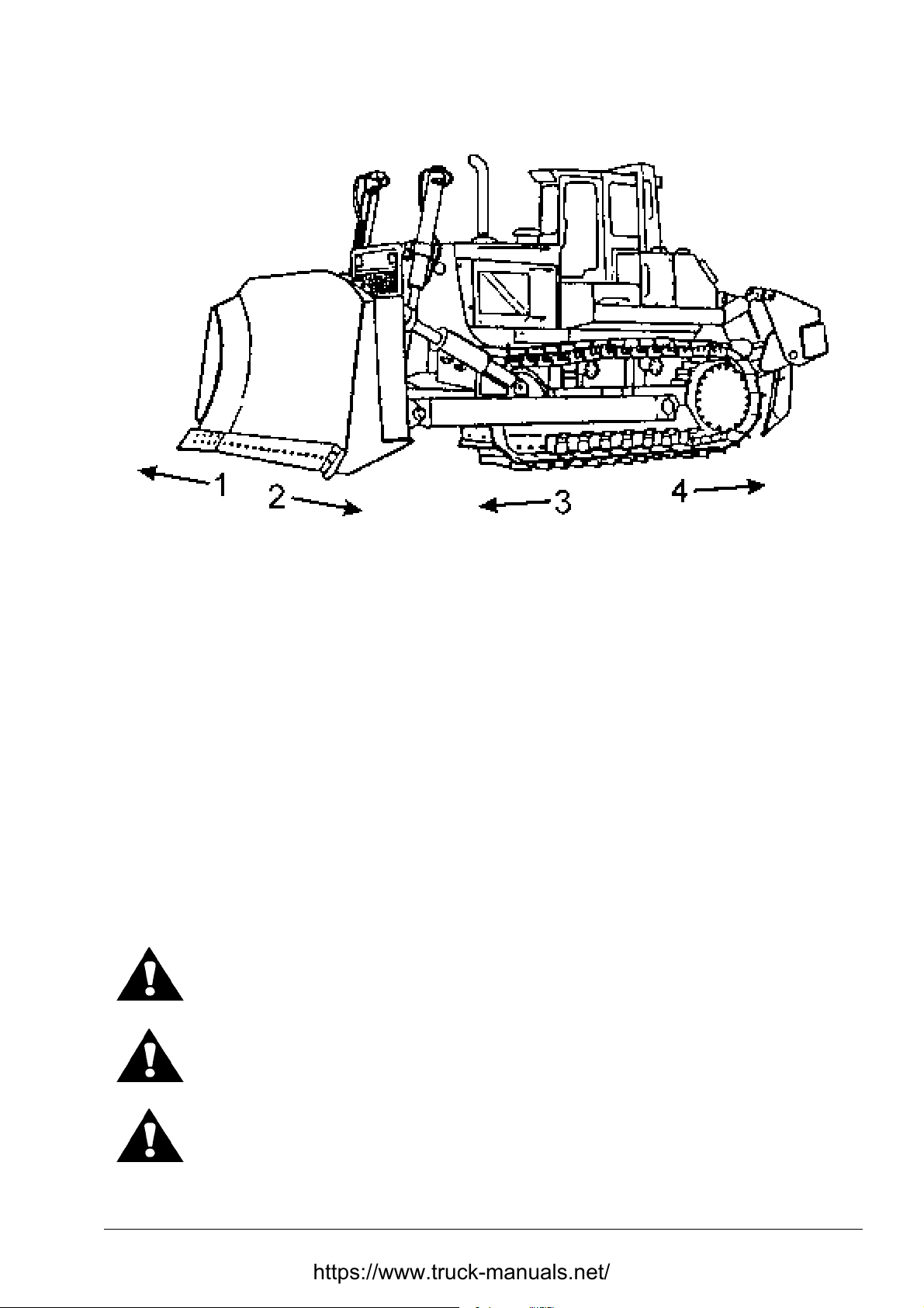
Fig. 1.1. TD-25 Series H Cr awler T r act o r Equipped with Bulldozer Blade
1. Right Hand Side of the Machine
2. Left Hand Side of the Machine
GENERAL
Throughout this manual there will be two types of cr oss references. One type is t o a heading in
another section. The other is to a heading within the same section. Unless it is other wise stated,
references will be to the same section. Refer to the section contents page at t he beginning of the
individual sections for specific page numbers.
Some illustrations are of general application and may not show your machine accurately in all
details.
Throughout this manual the use of the term s “left”, “right”, “front”, and “rear” must be understood
to avoid confusion when following instructions. “Lef t" and “right " indicate the left and r ight sides of
the machine when facing forward in the operat or 's seat. See Fig. 1.1.
The three following symbols and text in bold letters are used throughout this manual to call your
attention to instructions concerning your personal safety:
DANGER! It indicates an emergency which, if not avoided, may result in injury or
death. This sign calls your attention to a most serious danger.
3. Front of the Machine
4. Rear of the Machine
WARNING! ! This sign indicates an emergency which, if not avoided, may result
in injury or death.
CAUTION! This sign indicated an emergency which, if not avoided, may result i n
minor injury.
DRESSTA TD-25H
Page 11

SECTION 1
Page 4
INTRODUCTION
INTRODUCTION
The two following signs and text in italics are used throughout this manual to call your attention to
important procedures or steps having influence on the right functioning of a machine. Failure to
follow such instructions may result in the damage of a machine or affect m achine life time.
IMPORTANT: This sign and text in italics is used t hroughout this manual to call your at tention to
key problems for machine operation. Failure to follow such instructions may result in damage
of a machine and heavy material losses.
NOTE: This sign and text in italics is used throughout this manual to call your attention to an
important function having influence on the right functioning of a machine or for informational
purposes.
1.2. SERIAL NUMBERS
Fig. 1.2. Product Identification Number (P.I.N.) Fig. 1.3.Product Identification Number
(P.I.N.) on RMF
The product identification number (P.I.N.) is stamped on a plate attached to the front wall of the
control console at the left hand side of t he operator’s seat (Fig. 1.2). I t is also stamped on the r ear
frame in the upper right hand cor ner under the fender (Fig. 1.3).
TD-25H DRESSTA
Page 12

INTRODUCTION
SERIAL NUMBERS
SECTION 1
Page 5
Fig. 1.4. Serial Number Desig nat ion of Blade
The bulldozer model designation is stamped on the back of the blade, near the top right hand
corner (Fig. 1.4).
Fig. 1.5. Engine serial number plat e
The engine serial number and rating are designated on a plate attached to t he front of the engine
on the left hand side (Fig. 1. 5) .
All other components having serial numbers are equipped with a separat e ser ial num ber plate.
Use machine serial numbers when requesting infor mation or ordering parts and proper numbers
from the Parts Catalogue.
DRESSTA TD-25H
Page 13

SECTION 2
SAFETY PRECAUTIONS
Page 14

SAFETY PRECAUTIONS
SECTION 2
SECTION CONTENTS
PAGE
2.1. General .............................................................................................................................. 3
2.2. Before Starting the Engine ................................................................................................. 4
2.3. Operation ........................................................................................................................... 5
2.4. Maintenance ...................................................................................................................... 8
2.5. Shutdown ......................................................................................................................... 10
2.6. Safety Product Graphic Location ...................................................................................... 11
2.6.1. Safety Product Graphic ......................................................................................... 12
DRESSTA TD-25H
Page 15
SAFETY PRECAUTIONS
SECTION 2
Page 3
2.1. GENERAL
WORK SAFELY – FOLLOW THESE RULES
This symbol and text with bold letters is used throughout this manual to call
your attention to instructions concerning your personal safety. Observe and
follow these instructions. Be certain anyone operating and servicing this
machine is aware of these rules. Fail ure to foll ow t hese rules may result in injury
or death.
WARNING!: The machine can only be operated by a person who is familiar with
this manual, knows operation of the machine and its mechani sms, experienced
and properly licensed to operate such machines. Carefully observe and follow all
instructions provided in this manual.
The instructions and information given in this section do not cover all you ought to k now to operate
the machine safely. Detailed instructions regarding operational safety appear in the following
sections of this manual.
Human error is a contributing factor in most equipment -related injuries. Haste, carelessness and
lack of training are the primary causes of injuries.
Most operating injuries occur because of excessive speed, loss of control, failure to observe
warning signs, slipping or falling while entering or dismounting, a lack of bars on roadways or
piles, lack of a ROPS or seat belt , or not watching in the direction of travel.
Most maintenance injuries occur during welding or when using hammer s or wrenches. The most
common faults are improper work posit ion, a slipped tool, missed aim, a broken tool, f lying chips
and no welding hood.
Think before you act. A careful operator or maintenance man is the best insurance against an
accident.
Always wear proper safety equipment. Avoid wearing jewelry and loose fitting clothing; t hey could
catch on moving parts, which could result in serious injury or death. Hard hat, sturdy roug h-soled
work shoes or safety shoes, ear protectors, ref lective clothing, safety glasses and heavy gloves
may be required. Consult your employer for specific safety equipment requirements.
Each job site and application may have personal safety requirements. Carefully evaluate your
particular application and machine for equipment such as heater and defroster, all windshield
wipers, warning lights, side view and rearview mirrors, back-up alarms, fire extinguisher, rotat ing
beacons and additional lights. If in doubt, contact your distributor.
The machine should be equipped with a fully charged fire extinguisher. All personnel should be
instructed in proper usage. Recharge immediately after use. A dry powder fire extinguisher is
placed in the cab on the right hand side of the operator’s seat (Grammer seat, Fig. 2.1). It is
placed in a holder preventing uncontrolled movement during machine operation. In case of a f ire
the extinguisher can be easily removed from the holder. The extinguisher is provided with a label
containing the instructions of its use and application. The operator should be f amiliar with these
instructions.
DRESSTA TD-25H
Page 16

SECTION 2
Page 4
SAFETY PRECAUTIONS
GENERAL
Fig. 2.1. Fire Extinguisher Location
Do not jump on or off the machine. Keep two hands and one foot or two feet and one hand in
contact with the steps and grab handles and rails at all times.
Electrical system is 24-volt negative ground. Each machine is equipped with a starting receptacle.
It should be used when starting the machine using booster bat teries. In case the receptacle cannot
be used the following precautions must be taken to minimize chances of injury or damage to
electrical parts.
1. Turn the system master switch to the OFF posit ion.
2. At tach one end of the jumper cable to the positive ter minal of the booster bat ter y and the other
end to the positive terminal of the m achine bat tery.
3. Attach one end of the second cable to the negative terminal of the booster battery and the
other end to the machine's frame away from the battery.
4. To remove the cables, reverse the above sequence exactly to avoid sparks near the batt er y.
A frozen battery can explode when the booster cables are attached.
NEVER check battery charge by placing a metal object across the battery posts. Sparks can
cause an explosion. Use a voltmeter or hydrometer for checking.
Each new machine is equipped with a fire extinguisher, first aid kit and safety belt.
2.2. BEFORE STARTING THE ENGINE
Never start the engine indoors unless proper exhaust ventilation is provided to remove deadly
exhaust gases. Once the engine is operating , move the machine outdoors as soon as possible.
Exhaust gases are dangerous and can cause unconsciousness and death.
Always place the transmission shift lever in neutral, apply t he transmission neutral saf ety lock and
lock the parking brak e before starting.
TD-25H DRESSTA
Page 17

SAFETY PRECAUTIONS
SECTION 2
Page 5
BEFORE STARTING THE ENGINE
The operator must be alert, physically fit and free from the influences of alcohol, drugs or
medications that might affect his eyesight, hearing, r eact ions or j udgment.
Observe and know the use of alternative exits from the operator compartment.
Safety must always be the operator's most impor tant concern. He must ref use to operat e when he
knows it is unsafe and consult his supervisor when safety is in doubt. T he best safety device is
a safe operator.
Do not use controls or hoses as hand holds when climbing on or off the machine. Hoses and
controls can move and do not provide solid support. Movement of the controls may cause
inadvertent and unexpected movement of the machine or its equipment.
Follow all machine-mounted safety signs before starting, operating, maintaining or servicing the
machine.
Be sure the area of the operator 's compartment, all mounting steps and grab handles are f ree of
oil, grease, loose objects, ice and m ud to lessen the possibility of slipping. Remove or secure all
maintenance and personal items so they will not interfer e with the operator or jam the controls.
Perform a visual check of the machine before starting the engine. Look for such things as
improper fluid levels, oil leaks, and loose, damaged or missing parts. Do not star t the engine until
any unsafe conditions are corrected. Secure all caps and filler plugs.
Know and understand the traffic f low patter ns of your job and obey flagman, signs and signals.
Before entering the oper ator's com partment, clear the imm ediate area surr ounding the machine of
personnel and obstructions. Walk completely around the machine. After entering the operator's
compartment, sound the horn to clear t he immediate area of the machine.
Due to the danger of fire and explosion, never check or fill fuel tank or batteries near lighted
smoking materials or open flame or sparks.
2.3. OPERATION
Check work area for hazardous conditions. Be alert for soft ground conditions, especially when
working on slopes, near drop-offs or excavations or fill material, which could lead to sudden tipping
of the machine.
At night and times of poor visibility, carefully check the work area before moving in with the
machine. Use all lights provided.
Keep the windshield, windows and mirrors (if equipped) clean.
Before starting the engine, be sure you understand all control functions. Check all controls,
including the brakes, decelerator, steering and tr ansmission. Check all gaug es, warning light s and
safety devices. Correct any malfunctions.
Only one person, the operator, should be permitted to ride on the machine when it is in operation.
Perform an operational check of the machine in a safe area bef or e put ting it to work.
DRESSTA TD-25H
Page 18

SECTION 2
Page 6
SAFETY PRECAUTIONS
OPERATION
Keep operating controls, hands and shoes fr ee of g rease, water and mud to insur e posit ive contr ol
functions.
If the machine is ROPS equipped, for your personal protection, wear your seat belt. Bef ore driving
the machine, adjust the seat and f asten the seat belt. Adjust the seat belt to fit snugly and f low
around the hips to lessen the chance and severity of injury in the event of an accident. Never wear
the seat belt across the abdomen.
Check overhead clearance carefully before operating the machine in areas with low overhead
clearance, such as guy wires, power lines, bridges, low-hanging tree branches and building
entrances or exits. These overhead obstructions could cause an accident.
After starting the engine, but before moving the machine, warn nearby personnel by giving
a couple of short horn blasts.
Be sure that the rear screen is securely fastened to the ROPS structure before operating the
winch. Operating without properly installed screen could result in serious injuries. Operate the
winch from the driver’s seat only. Always engage the parking brake before winching, if the
machine is stopped. Use caution when installing or removing cable from the winch. Keep all
persons clear of a cable under tension. Never use a cable that is damaged. Failure to follow these
precautions could result in serious injuries.
Never mix gasoline, gasohol and/or alcohol with diesel fuel. This pr actice creates an extreme fire
hazard and under certain conditions an explosion, which could result in personal injury or death.
Do not smoke when refueling or ser vicing the machine. A fire could result.
Never place gasoline or diesel fuel in an open pan.
Never remove the fuel tank filler cap or refill the f uel tank while the engine is running or hot or when the
machine is indoors. Fumes are dangerous, a spark or flame could result in a fire or explosion.
On machines equipped with a suction fan or a reversible f an in the suction position, periodically
check the engine exhaust system for leak s. Exhaust gases are dangerous to the operator.
Do not operate the machine in the condition of extreme fatigue or illness.
Be sure that the rear screen is securely fastened to the RO PS structure. Be sure chains or cables and
their anchor points are strong enoug h to handle the expected load. Inspect carefully f or flaws before
using.
Always wear gloves when handling cables and chains. Avoid looping or knotting a cable or chain.
Do not pull with kinked chain or cable as excessively high stress in the area of bending may
cause a failure in the kinked area. Cables or chains for towing or winching should be fast ened to
the designated to this purpose attachment points only. Be sure the pins are attached securely
before pulling. Stand clear of chains or cables under load.
Keep the engine exhaust system and exhaust manifold clear of combustible material for your
personal protection.
Know the locations of underground cables, water mains, g as lines, etc. A ruptured g as line or cut
electrical cable could result in personal injury or death.
TD-25H DRESSTA
Page 19

SAFETY PRECAUTIONS
SECTION 2
Page 7
OPERATION
When leaving a machine unat tended fo r any length of time, m ake sure t he transmission shift lever
is positioned and locked in neutral (N), the blade is com pletely lowered, t he eng ine is st opped, t he
parking brake is applied, and t he electric master switch is in the “off” position. If the machine is
equipped with a cab make sure that the cab is locked.
Before operating a machine read and know the Operator’s Manual and all Safety Product Graphic.
The roll-over protective structure (ROPS) provides the operator’s protection in the event of
machine rollover or upset. This structure is designed to bend during a rollover to protect the
operator from sudden impact loads.
When operating a machine, look in the intended direction of travel to be sure personnel or allied
equipment does not interf er e with the m achine work pat tern.
Never try to get on or off a machine while it is moving. A serious injury or death could result.
Never shift the transmission into neutral (N) when traveling downhill. The machine may go out of
control and a rollover could result or the transmission, torque converter or engine could be
damaged when the transmission is again placed in gear. Always put the transmission in low rang e
position before starting downhill. Use the deceler ator and brake pedal to slow the machine.
Avoid side hill travel whenever possible. Drive straight up and down the slope. If the machine
starts slipping sideways on a grade, turn downhill immediately.
If possible avoid crossing obstacles such as ridges, rocks or logs. If you can't avoid them , reduce
speed and ease over the obstacle at an angle.
Machine's weight and the vibration it creates can cause the edge of a hig h wall to collapse. Keep
your machine back from the edges of banks and excavations. If it cannot be avoided drive the
machine at the straight ang le t o the edge.
Travel slowly in congested areas or on rough ground, slopes or near drop-of fs or on snow, ice or
slippery surfaces.
Maintain a safe distance between your machine and other vehicles according to the condition of
the road and load.
Never hold the hydraulic controls in their extreme position after the equipment has reached its
maximum travel. This could cause overheating of t he hydraulic system.
Do not adjust the seat position while the machine is in motion. A loss of control may result.
Completely stop the machine, apply and lock the parking brake and then adjust the seat.
Never use the blade as a brake except in an emergency.
Carry the blade low for maximum stability and visibility.
Where noise exposure exceeds the levels defined by proper health and safety authorities and
applicable standards wear authorized ear protective equipment.
DRESSTA TD-25H
Page 20

SECTION 2
Page 8
SAFETY PRECAUTIONS
2.4. MAINTENANCE
Trained personnel in machine operation and their helper s only are allowed to take t he operator' s
seat while doing maintenance or repairs on a machine. Authorized personnel only is allowed to
control, maintain or repair a m achine.
Do not hasten. It may cause accidents.
Put objects onto a machine standing on t he level ground before you climb on the machine.
Loosen the radiator cap slowly to relieve all pressure in the system and use caution when
removing the cap to prevent possible injury.
Have all equipment resting on the gr ound or blocked before removing any hydraulic component.
Actuate the control levers in opposite directions t o r elieve all pressur e from the system.
Never work beneath a blade or ripper without proper blocking. Improper blocking could result in
serious injuries.
When service or maintenance requires access to areas that cannot be r eached from the ground,
use a ladder or platform. If such ladders or platform s are not available, use the machine’s hand
holds and steps provided. Perfor m all ser vice or m aintenance carefully.
Use only approved parts for repairs and maintenance shown in your parts catalog . Failure to do so
could compromise your personal safety and machine’s performance and reliability.
Never align holes with fingers or hands. Use a proper aligning tool.
Be sure all tools are in good condition. Do not use tools which are worn, bent or have
mushroomed heads. Use the proper tool for the job. Remove sharp edges and burrs from
reworked parts.
For field service, move the machine to the level gr ound, if possible and block the tracks . If work is
absolutely necessary on an incline, block the machine and its attachments securely. Move the
machine to the level ground, as soon as possible.
Before working on a machine, turn OFF the electric system master switch and tak e the key out so
no one will start it unexpectedly.
Do not carry loose objects in your pockets that m ight catch on the machine or f all unnoticed into
open compartments.
Before working on any part of t he engine or electric system, disconnect the bat tery ground cable.
Tag the cable and all controls to alert per sonnel that work is in progress.
When it is necessary to make any checks or adjustments with the eng ine running, always use two
people. One trained person must be in the operat or's seat to saf eg uard t he second person mak ing
the checks or adjustments.
As an additional precaution, when making checks or adjustment s with the engine running, make
sure the transmission shift lever is lock ed in neutral (N), and the parking br ake is locked.
Never stand on the tracks or near the blade while the eng ine is r unning.
TD-25H DRESSTA
Page 21

SAFETY PRECAUTIONS
SECTION 2
Page 9
MAINTENA NCE
If the engine is running and t he side doors are open or r emoved be careful of rotating parts such
as the fan and belts that can cause serious injur y.
Never operate the engine when cleaning or lubricating the machine. Serious injury could result
from contacting moving part s .
Use a non-toxic, nonflammable commercial solvent f or cleaning parts. Never use gasoline, diesel
fuel, kerosene or other flammable solvents for cleaning a part .
Excessive or repeated skin contact with sealant or solvents may cause skin irritation. In case of
skin contact, remove sealant or solvent promptly by washing with soap and water. Follow the
manufacturer’s advice whenever cleaning agents or other chem icals ar e used.
Lower the blade and/or the ripper before making hydraulic adjustments. To prevent personal
injury, be sure the personnel are standing out of the way of the blade when it is being lowered.
Never allow anyone to walk under or be near unblocked raised equipment.
Provide proper ventilation when operating in a closed building to avoid danger of exhaust gases.
Exhaust gases are dangerous and can cause poisoning, unconsciousness and death.
Hydraulic fluid escaping under pressure from a very small hole can be almost invisible, yet have
sufficient force to penetrate the skin. Use a piece of cardboard or wood to search for suspected
leaks. Do not use hands. If injured by escaping fluid, see a doctor at once. Serious infection or
reaction can occur if proper medical treatment is not administered immediately.
Wear proper protective equipment such as goggles or saf ety glasses with side shields, hard hat,
safety shoes and heavy gloves when metal or other particles are apt to fly or fall. Many of
a machine's parts are hardened and can chip.
Lift and handle all heavy parts with a lifting device of pr oper capacit y. Be sure parts ar e secured by
proper slings and hooks. Use lif t ing eyes if provided. W ar n people in the area to stand clear.
Do not attempt to repair a ROPS pr otective structur e aft er an accident. Repair ed structures do not
provide the original strength and protection. Contact your distributor for infor mation on structure
replacement. Do not operate the machine again until the ROPS has been replaced.
Do not cut, grind, weld, drill or tap holes in the ROPS. This could weaken the st ructure, or affect
the overall energy absorption capabilities.
When using com pressed air for cleaning parts, wear gog gles or safety glasses with side shields.
Use a nozzle, which limits the pressure to 200 [kPa].
Do not use an open flame to check f or leaks or fluid levels anywhere around a machine.
Keep work area clean and dry. Remove oil and water spills immediately. Do not pile up oily or
greasy rags. They are a fir e hazard. St or e them in an approved, closed metal container.
Use a soft iron or nonferrous hammer to install or rem ove ripper teeth. It is danger ous to hammer
on teeth. Wear safety glasses with side shields or goggles to r educe t he chances of injury.
Batteries give off a highly inflamm able gas. Never allow sparks or open flame near the batter ies.
A fire or explosion could occur. Do not charge bat t eries in a closed area. Provide proper ventilation
to guard against accidental explosion of an accumulation of the explosive gas given off in the
charging process. When installing batteries, be sure the electric master switch is in the "OFF"
position. Be sure to connect the positive cable to the positive terminal and the neg ative (ground)
cable to the ground of the ma chine.
DRESSTA TD-25H
Page 22

SECTION 2
Page 10
SAFETY PRECAUTIONS
MAINTENA NCE
Ether starting fluid is f lam mable. Follow the precaut ions print ed on the cont ainer. An explosion can
result if sparks or f lam e contact et her in a cont ainer or if a container is st ored in an area where t he
temperature exceeds 70 [°C]. Observe the following precautions:
1. Follow the correct method for starting the engine. Refer to "STARTING THE ENGINE", Section
4.
2. Do not use the ether injector when the ambient tem perature is above freezing.
3. For your own personal safety, always remove the ether container when welding, grinding or
using a torch on a machine.
4. Do not let ether come in contact with your skin, as it can cause local freezing.
5. Do not breathe in hazardous ether vapor.
6. Keep a fluid container out of reach of children.
7. Never puncture a fluid container or put it int o fire. Dispose of an empty container pr oper ly.
8. Do not store fluid containers in the operat or's compartment.
Never mix gasoline or alcohol with diesel fuel. This creates an extreme f ire or explosion hazard,
which could result in personal injury or death.
Do not use bleach, color dye or solvents on the seat belt webbing. This m ay cause a severe loss
of tensile strength. This could cause the webbing to break resulting in personal injury. It is
recommended that the seat belt be cleaned only with warm water and mild deterg ent .
2.5. SHUTDOWN
If parking on or near traff ic lanes cannot be avoided, provide appropriat e flag s, barriers, flares and
warning signals. Also provide advance-warning signals in the traffic lane for approaching traffic.
Park the machine in a non-operating and non-traffic area. Park the machine on level ground
whenever possible. If you must park on a slope, park at the right angle to the slope. Apply and lock
the brake pedal.
Never leave a machine unattended with the engine running.
When leaving a machine unat tended, slowly lower the hydraulic equipment to t he ground, shift the
transmission into neutral and lock the neutral lock lever, shut off the engine, apply and lock the
parking brake. Relieve any pressure in the hydraulic system by moving the controls in both
directions. Turn off the electric system master switch and take the key out. Always lock up the
machine when leaving it unattended, including any anti-vandalism attachment s.
Do not jump off a m achine.
When operating in bad weather and storm lightening is nearby, dismount and seek shelter away
from the machine. Lightening will be attracted to the machine and can cause serious injury or
death.
When a machine is to be loaded onto a transpor t truck and t railer do so caref ully. Load only when
the trailer is level. The steel track shoes will slide easily on the trailer. When the machine is
properly positioned chain it securely so it can not move on the trailer.
Keep away your head, body, feet, hands and fingers fr om a blade or ripper when they are in a
raised position.
TD-25H DRESSTA
Page 23

SAFETY PRECAUTIONS
SECTION 2
Page 11
SHUTDOWN
Do not allow the hydraulic system to support the mounted equipment when leaving a machine
unattended, to eliminate possibility of an unexpected dr op of the blade or ripper.
2.6. SAFETY PRODUCT GRAPHIC LOCATION
Fig. 2.2. Safety Product G r aphic Location – Machine
1. Track Adjuster Decal
2. Door Decal
3. ROPS Decal
4. Pressurized Reservoir Decal
DRESSTA TD-25H
Page 24
SECTION 2
Page 12
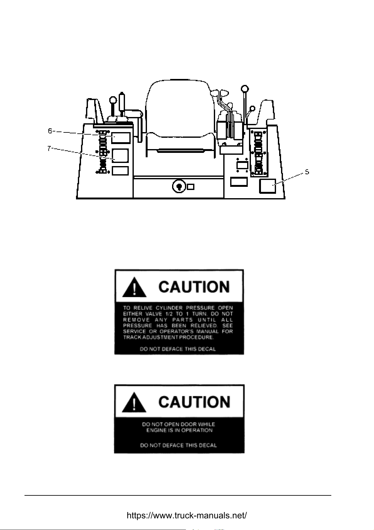
5. General Decal
6. Instruction Decal for locking the lever to prevent incidental movement of a machine.
7. Safety Decal
SAFETY PRECAUTIONS
SAFETY PRODUCT GRAPHIC LOCATION
Fig. 2.3. Safety Product G raphic Location – Cab
2.6.1. SAFETY PRODUCT GRAPHICS
Decal 1
Decal 2
TD-25H DRESSTA
Page 25

SAFETY PRECAUTIONS
SAFETY PRODUCT GRAPHIC LOCATION
DRESSTA
DRESSTA Co. Ltd. THE PROTPROTECTION
DRESSTADRESSTA
Decal 3
SECTION 2
Page 13
Decal 4
Decal 5
DRESSTA TD-25H
Page 26

SECTION 2
Page 14
SAFETY PRECAUTIONS
SAFETY PRODUCT GRAPHIC LOCATION
Decal 6
Decal 7
TD-25H DRESSTA
Page 27

SECTION 3
MACHINE TRANSPORT AND STORAGE
Page 28

MACHINE TRANSPORT AND STORAGE
SECTION 3
SECTION CONTENTS
PAGE
3.1. Machine Transport ............................................................................................................. 3
3.1.1. General .................................................................................................................. 3
3.1.2. Truck ...................................................................................................................... 3
3.1.3. Railroad Flat Car .................................................................................................... 3
3.2. Lifting a Machine on Slings ................................................................................................ 4
3.3. Moving a Disabled Machine ............................................................................................... 4
3.4. Machine Storage ................................................................................................................ 6
3.4.1. Preparing for Storage .............................................................................................. 6
3.4.2. Servicing Machine During Storage .......................................................................... 8
3.4.3. Preparing for Operation after Storage ..................................................................... 8
DRESSTA TD-25H
Page 29
MACHINE TRANSPORT AND STORAGE
SECTION 3
Page 3
3.1. MACHINE TRANSPORT
3.1.1. GENERAL
IMPORTANT: When shipping this machine by high-speed means of tr ansport secur e the air int ake
cap and the exhaust outlet to protect the turbocharger from damage. Turn the system master
switch to the OFF position.
WARNING! When transporting a machine, use caution when loading and
unloading. Load and unload a machine in a level area which fully supports the
machine and the transport vehicle so it cannot move. Use loading ramps of
adequate strength, low angl e and proper hei ght .
3.1.2. TRUCK
When shipping this machine by truck learn oblig atory regulations. Contact local aut horities for the
proper shipping and loading regulations.
When preparing to transport a machine by truck , have the t r uck and trailer level.
1. Use ramps or loading dock to maintain stability.
2. Drive the machine in its lower gear.
3. Use the lowest engine speed that will move the machine and without stalling the engine.
4. T he machine can be "inched" into place by holding the steering hand levers back and slowly
moving them forward into the dr iving position. (Be caref ul and move t he levers simultaneously
otherwise the machine will turn).
5. Pulling the steering hand levers back will disconnect the drive. Pulled back part way they will
permit the machine to roll freely.
6. When the machine is properly located, stop the engine, place the transmission control in
Neutral (N), apply the Transmission Neutral lock Lever, apply and lock the brakes and turn t he
master switch OFF.
7. Tie the machine down securely by ropes or wires and by wooden blocks to prevent
unintentional movement.
DANGER! Failure to secure the machine to the truck in a proper way during
transporting can result in property damage, personal injury or death.
3.1.3. RAILROAD FLAT CAR
Respective railroad loading rules and specifications must be followed when shipping this machine
on open top railroad cars.
DRESSTA TD-25H
Page 30
SECTION 3
Page 4
MACHINE TRANSPORT AND STORAGE
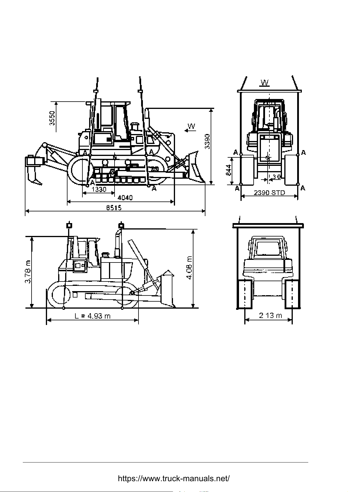
3.2. LIFTING MACHINE ON SLINGS
Fig. 3.1. Lifting Machine on Slings
1. Use slings of sufficient strength for m achine weight .
2. At tach slings under the machine as shown in the drawing in the places marked by the let ter „A”
in the way preventing sliding of the sling from the track shoe and moving the track itself.
3. Attach spreader bars to the lif ting slings to prevent them f rom slipping off.
4. Standard machine weight with a cab, ROPS structure, air conditioner, blade and ripper is
38,620 [kg].
TD-25H DRESSTA
Page 31

MACHINE TRANSPORT AND STORAGE
SECTION 3
Page 5
3.3. MOVING A DISABLED MACHINE
CAUTION! When using a chain or cable, be sure it is strong enough for the
expected load and is properly secured to the drawbar pins or tow hooks
(if equipped).
WARNING! When pulling with a chain or cable, take up the slack slowly to avoid
jerking. A chain or cable which fails under load can whip and cause serious
injury. Stand clear. Do not pull or tow unless the operator's compartment is
guarded against or out of reach of a whipping chain or cable. Attach only to the
machine tow hook or drawbar. Fail ure to follow these instructions could cause
serious injury.
IMPORTANT! A machine MUST NOT be t owed if the steering drive, final drive or their parts or
subassemblies are out of order. It m ust be t r ansported to avoid further damage.
To avoid a possibility of power train damage, limit towing to a distance of 1 [ km] at speeds less
than 2 [km/h]. The brakes on this machine are spring applied automatically when the engine is
stopped or the steering hydraulic system f ails, and can only be released hydraulically.
DRESSTA TD-25H
Page 32

SECTION 3
Page 6
MACHINE TRANSPORT AND STORAGE
MOVING A DISABLED MACHINE
The diagnostic center (Fig. 3.2) has a quick couplers RB and L
hydraulic pressure to the LH and RH brake spools to release t hem prior to towing as described in
the procedure specified below.
Fig. 3.2. Diagnostic Center – Tow and Pressure Check Ports
1. Right Brake Quick Coupler
2. Left Brake Quick Coupler
for application of external
B
If the tractor can be towed and the engine and steering hydraulic system can be operated,
proceed as follows:
1. Shift the transmission shift lever in "NEUTRAL" and lock it with the lever (A, Fig. 4.7)
2. Start the engine.
3. Release the brake and decelerator pedal.
4. Use a towing cable of sufficient str ength. Keep the engine running in the middle r ange of the
idle speed and hold transmission shift lever locked in “NEUTRAL” during the tow.
If the tractor can be towed but the engine and/or steering hydraulic system is inoperable pr oceed
as follows:
1. Shift the transmission shift lever in "NEUTRAL" and lock it with the lever (A, Fig. 4.7)
2. Open the diagnostic center cover on the LH side of the machine and connect a lubricating
fitting and pressure gauge to one of the quick coupler s ( por t 1 or 2, Fig. 3.2).
3. Release the decelerator and brake pedal.
4. Pump sufficient g rease into one of the ports to release the brakes. The connected pressure
gauge should show a pressure of 830 - 1030 [k Pa]. The amount of g rease required depends
on the amount of pressure dissipation in the system .
5. Use a towing cable of suf ficient strength. During the t ow, it may be necessary to pump more
grease into the quick coupling to make up for the loss of pressure.
6. Depressing the decelerator and brake pedal will relieve hydraulic pressure and apply the
brakes.
7. After towing is completed, actuate the steering levers until all grease is purged from the
system and the pressure drops to zero (as measured on the brak e port) while the decelerator
and brake pedal is depressed and the steering levers ar e in t he br aking position.
8. Close the diagnostic center cover after disconnect ing the lubricating fitting.
TD-25H DRESSTA
Page 33

MACHINE TRANSPORT AND STORAGE
SECTION 3
Page 7
3.4. MACHINE STORAGE
3.4.1. PREPARING FOR STORAGE
When a machine is tak en out of service and stored f or more t han 30 days, steps must be tak en t o
protect the machine. Leaving the equipment outdoors exposed to the elements will materially
shorten its life. An enclosure will protect a m achine from rapid temperature changes and lessen
the amount of condensation that forms in hydraulic component s, engine, fuel tank and f inal drives.
If it is not possible to put a ma chine in an enclosur e, cover it with a tarpaulin.
After a machine has been positioned for storage and the engine shutdown, perf orm the following
operations:
1. Visually inspect the machine for external leakag e and other defects.
2. Clean the radiator, ref er to “COOLING SYSTEM”, Section 5.
3. Thoroughly clean the machine, be sure to rinse off any corrosive residue.
4. Correct any defects found. Consult Authorized Distributor of Construction Equipment, if
necessary.
5. Clean or replace the air cleaner filter elements. Refer to “ AI R CLEANI NG SYSTEM”, Section 5.
6. The cooling system should be completely drained, chemically flushed, and refilled with
a conditioned water/antifreeze solution suitable for the lowest temper atur e anticipat ed. Ref er to
"COOLING SYSTEM", Section 5 f or t he proper antifreeze and conditioner concentrations.
IMPORTANT: Under no circumstances should a vehicle be stored wit h a dry cooling syst em.
7. Drain the condensation water from t he fuel tank. Refer t o “FUEL SYSTEM”, Section 5.
8. Remove and reinstall new fuel filters. Refer to “FUEL SYSTEM”, Section 5.
9. It is recommended to use fuel stabilizer in the quantity as instructed by the manufacturer.
Stabilizer will prevent degradation of fuel, sludge buildup and st ops the growth of bacteria in
fuel during storage. Fuel stabilizer may be purchased from:
FUEL PREP 1000
NALCO CHEMICAL COMPANY
2901 BUTTERFIELD ROAD
O AK BROOK, ILLINOIS 60521, USA
or machines di st ributor
10. Add 120 [ml] of volatile corrosion inhibitor “VCI” for each 100 liters of t otal fuel capacity to th e
fuel tank. "VCI" pr ovides corrosion protection by contact with metal, and in a closed system,
the vapors provide sufficient protection for areas that are not in contact with fuel. "VCI" may be
purchased from:
NOX RUST VCI # 105 OIL
DAUBERT CHEMICAL COMPANY
1200 JO RI ES BLVD
O AK BROOK, ILLINOIS 60521, USA
or machines di st ributor
WARNING! Rust inhibitors are volatile and flammable. Prepare the machine in
a well ventilated pl ace. Keep away from open flame or sparks. DO NO T SMOKE.
Store the container in a secure, cool, well ventilated place.
DRESSTA TD-25H
Page 34

SECTION 3
MACHINE TRANSPORT AND STORAGE
Page 8
MACHINE STORAGE
CAUTION! Due to the volatile nature of "VCI", irritation of eyes and skin may
occur. Prolonged exposure to the vapors or oil should be avoided.
11. Start the engine and run in the middle range of idle speed, no load, for approximately
4 minutes and then stop the engine.
12. Lubricate all points of the machine as outlined in the “SERVICE GUIDE”, Section 5.
NOTE: Be sure to oil or grease all linkage connections, joints, nuts, pins, shaf ts, and bushings not
covered in the “SERVICE GUIDE”.
13. Drain the crankcase oil from the engine, replace the lubricating oil filter and refill with the
specified oil. Refer to "ENGINE", Section 5.
14. Add 15 [ml] of "VCI" for each liter of eng ine oil capacity to the crank case. ( Example: if t he tot al
crankcase capacity is 10 liters, add 150 [ml] of VCI to the crankcase).
15. Start the engine and run it in the middle range of idle speed, no load, for approximately 30
seconds and then stop the engine.
16. Remove the air intake cap.
17. Pour 120 [ml] of " VCI" into t he intake m anifold to pr ovide suff icient corrosion pr otection for the
area between the top of the piston and the bott om of the cylinder head.
18. Add 350 [ml] of VCI to the hydraulic reservoir.
19. Seal all external openings (i.e. engine exhaust out let, crankcase and hydraulic breathers, fuel
vent line, air intake, etc.) with waterproof tape wide enough to cover the opening reg ardless of
its size.
NOTE: W hen sealing with tape, be sure t o extend the tape approximat ely 25 mm beyond opening
to insure a good seal.
20. Remove the batteries and store them in a cool, clean, dry, well ventilated place away from
areas of storing or dispensing fuel and oil, not near any heat source and preferably where the
temperature range is between 0 [°C] to +21 [°C]. Be sure the batteries ar e fully charged.
IMPORTANT: Do not leave batteries on a concr et e floor or in freezing temperatures.
IMPORTANT: If a machine is stored with dry-charged batteries or no batteries, the alternator
output lead must be disconnected and insulated. Failure to do so may result in permanent damage
to the alternator. Connect the output lead only after the batteries have been activated with
electrolyte. Refer to "ELECTRICAL SYSTEM", Section 5.
21. If the blade is detached for storage, secure the cylinders to the machine to avoid damage.
22. Coat all machined, unpainted surfaces with chassis grease to prevent rust.
TD-25H DRESSTA
Page 35
MACHINE TRANSPORT AND STORAGE
SECTION 3
Page 9
MACHINE STORAGE
3.4.2. SERVICING MACHINE DURING STORAGE
ONE-MONTH REPETITIVE SERVICE PERIOD
MACHINES EQUIPPED W ITH MAINTENANCE-FREE BATTERIES
Check if batteries are fully charged. Never allow batteries to run down below ¾ full charge.
SIX-MONTH REPETITIVE SERVICE PERIOD
1. Visually inspect the engine and radiator f or leakage and other defects. Correct all def ects. If
necessary, consult Authorized Distributor of Construction Equipment.
2. Remove all storage seals from the m achine. (i.e. crankcase and hydraulic breathers, eng ine air
intake, fuel tank vent lines, etc.).
3. Install fully charged batt er ies. Refer to "ELECTRICAL SYST EM", Sect ion 5.
IMPORTANT: Check that batteries are level in the holder and securely held. The hold-down
fasteners should hold the batteries firmly but not tight enough to w arp or damage eit her the holddown bar or batteries.
WARNING! The battery cable shoes should be so arranged that access to the
plugs is ensured. Lay the cables so that the wires should not rub hold-down
bars or its fasteners. Always connect the negative ground cable last to minimize
the chance of sparks or explosion.
4. Check t he coolant level in the radiat or and add proper concentrat ions of ant if reeze and coolant
conditioners, if requir ed. Refer to “COOLING SYSTEM”, Section 5.
NOTE: If excessive loss of coolant is detected, the problem should be corrected. Refer to
“COOLING SYSTEM”, Section 5.
5. Perform steps 7 through 22 of "PREPARING FOR STORAGE".
3.4.3. PREPARING FOR OPERATION AFTER STORAGE
1. Visually inspect the machine for external leakag e and other defects.
2. Clean the radiator, ref er to “COOLING SYSTEM”, Section 5.
3. Thoroughly clean and wash the machine.
4. Correct any defects found. Consult Authorized Distributor of Construction Equipment if
necessary.
5. Remove all storag e seals f rom the machine ( i.e. crank case and hydraulic breathers, engine air
intake, fuel tank vent lines, etc.).
6. Replace the air cleaner filter elem ent s. Refer to “AIR CLEANING SYSTEM”, Section 5.
7. Remove and discard fuel filters and replace with new ones. Refer to “FUEL SYSTEM”,
Section 5.
8. Fill the fuel tank with approved diesel fuel. Refer to “REFILL SPECIFICATIONS AND
CAPACITIES CHART”, Sect ion 5.
9. Lubricate all points of the machine as out lined in t he “ SERVICE GUIDE”, Section 5.
DRESSTA TD-25H
Page 36
SECTION 3
MACHINE TRANSPORT AND STORAGE
Page 10
MACHINE STORAGE
NOTE: Be sure to oil or grease all linkage connections, joints, nuts, pins, shaf ts, and bushings not
covered In the "SERVICE GUIDE".
10. Drain the engine oil from the crankcase and replace the engine lubricating oil filter. Refer to
“ENGINE”, Section 5.
11. Install fully charged batteries. Refer to “ELECTRICAL SYSTEM”, Section 5.
IMPORTANT: Check that the batteries are level in the holder and securely held. The hold-down
fasteners should hold the batteries firmly but not tight enough to w arp or damage eit her the holddown bar or batteries.
WARNING! Battery cable shoes are arranged in a way that access to the battery
plugs is ensured. Battery cables should not rub hold-dow n bars or its fasteners.
Always connect the negative ground cable last to minimize the chance of sparks
or explosion.
12. Start the engine, refer to “ENGINE START AFTER OIL CHANGE OR PROLONGED
STANDSTILL”, Section 4. Observe all the gauges on the instrum ent panel f or proper operat ion
of the engine.
WARNING! Never start an engine indoors unless proper exhaust ventilation is
provided. Once the engine is running, move the machine outdoors as soon as
possible.
IMPORTANT: Crank the engine for a period of 30 seconds then allow the cranking motor t o cool
for two or three minutes bef or e cr anking again t o avoid damaging the cranking motor.
TD-25H DRESSTA
Page 37

SECTION 4
OPERATING
Page 38

Page 39

OPERATING SECTION 4
SECTION CONTENTS
PAGE
4.1.Machine Precautions........................................................................................................... 3
4.2.Universal Symbols for Instruments and Controls ................................................................ 4
4.3.Instrument Panel ................................................................................................................ 6
4.4.Cab Controls ...................................................................................................................... 9
4.5.Controls and Adjustment .................................................................................................. 10
4.5.1. Seat ...................................................................................................................... 10
4.5.2. Seat Belt ............................................................................................................... 11
4.5.3. Engine Speed and Shut Down Lever .................................................................... 12
4.5.4. Transmission Neutral Lock Lever ......................................................................... 13
4.5.5. Transmission Shift Lever ...................................................................................... 13
4.5.6. Hand Steering Levers ........................................................................................... 14
4.5.7. Brake and Decelerator Pedal ................................................................................ 14
4.5.8. Brake and Decelerator Pedal Lock ....................................................................... 15
4.5.9. Electric System Master Switch .............................................................................. 15
4.5.10.Equipment Control Levers .................................................................................... 16
4.6.Starting the Engine .......................................................................................................... 17
4.6.1. Normal Start ......................................................................................................... 18
4.6.2. Ether Injector Start ............................................................................................... 19
4.6.3. Engine Start after Oil Change or Prolonged Standstill .......................................... 20
4.7.Stopping the Engine ......................................................................................................... 20
4.8.Tips for Engine Safeguarding .......................................................................................... 21
4. 9. Driving the Machine ......................................................................................................... 21
4.10.Shifting the Transmission ................................................................................................. 22
4.11.Converter Overheating ..................................................................................................... 23
4.12.Steering the Machine ....................................................................................................... 23
4.12.1. Gradual Turn ...................................................................................................... 24
4.12.2. Pivot Turn .......................................................................................................... 24
4.13.Downgrade Operation ...................................................................................................... 24
4.14.Operating Over an Obstruction ........................................................................................ 24
4.15.Stopping the Machine ...................................................................................................... 25
4.16.Parking the Machine ........................................................................................................ 25
4.17.Operating Mounted Equipment ........................................................................................ 26
4.17.1. Blade Control Lever ............................................................................................. 26
4.17.1.1. Hold ..................................................................................................... 27
4.17.1.2. Raise .................................................................................................... 27
4.17.1.3. Lower.................................................................................................... 27
4.17.1.4. Float...................................................................................................... 27
4.17.1.5. Tilt ........................................................................................................ 28
4.17.1.6. Pitch ..................................................................................................... 28
DRESSTA TD-25H
Page 40

SECTION 4 OPERATING
Page 2
4.17.2. Ripper Control Levers ......................................................................................... 28
4.17.2.1. Ripper Shank Pitch ............................................................................... 29
4.17.2.2. Ripper Raise and Lower ....................................................................... 29
4.17.2.3. Pin Puller Control Lever ........................................................................ 29
4.18. Blade Positions ................................................................................................................ 30
4.18.1. Bulldozer Blade Positions .................................................................................... 30
4.18.1.1. Tilting the Blade................................................................................. 30
4.18.1.2. Pitching the Blade ............................................................................. 31
4.18.1.3. Levelling the Blade............................................................................ 31
4.19.Operating Techniques ...................................................................................................... 32
4.19.1. Digging and Clearing .......................................................................................... 33
4.19.2. Transporting , Piling or Loading ........................................................................... 37
4.19.3. Breaking Piles and Spreading ............................................................................ 38
4.19.4. Ripping ............................................................................................................... 39
4.19.4.1. Prior to Operation ............................................................................... 39
4.19.4.2. Ripping Techniques ............................................................................ 40
4.19.4.3. Cold Weather Operation ..................................................................... 40
4.20. Economical Operation of the Machine ............................................................................ 40
TD-25H DRESSTA
Page 41

OPERATING SECTION 4
Page 3
4.1. MACHINE PRECAUTIONS
During operation stay alert and watch what you are doing. Use common sense and do not operate
when fatigued.
Know your machine.
For your personal safety read this manual carefully and follow all instructions and precautions.
Refer to and read Section 2 carefully and follow all precautions.
Before starting or operating this tract or, read the following general precautions. These are listed
there to help you protect the machine and to remind you of protection for yourself and those
around you. Sound judgment and observance of these rules will help make your job a safer one.
Visually check out the machine for leak s and broken, missing or malfunctioning parts. Be sur e all
caps, dipsticks, battery caps, etc. are secure before starting. Correct any problems before
operating the machine.
Before starting operation, check the machine for correct function of steering controls, brake
controls, hydraulic controls, instruments and safety equipment. Make all necessary repairs or
adjustments before operat ing the machine.
Keep the transmission in low gear when going downhill. Never coast downhill with the transmission
in neutral. The machine could go out of control and tip over. Always drive the m achine slowly when
on hillsides, ramps or rough terrain. Be extremely careful when working around t renches or bank s.
Failure to do so could cause the machine to roll over.
Do not place the tractor under load without the proper engine oil pressure and operating
temperature. After starting the engine, move the engine speed control lever to the low idle
position. Allow the engine to run at low idle for 3 to 5 minutes at 1000 [RPM] until normal oil
pressure registers on the gauge t o obtain complete distribution of the lubricating oil. Oil pressure
after 15 seconds must be correct. Do not idle the engine for more than 10 minutes.
To prevent any possible damage to the alternator, the electric system master switch must be in the
“ON” position when the engine is running. The switch must be in the “O FF” position only when the
engine is shut down at the end of each day or when the operator leaves the tractor unattended.
If the tractor is left outside during cold weather and the tracks become frozen to the ground, do not attempt
to jerk them free with the power of the eng ine. St art the tr actor slowly and, if the t rack s do not br eak f ree,
pry them loose. To prevent the tracks from freezing in the ground, park the tractor on planks.
In freezing weather thoroughly clean all ice and mud from the track system after each day's
operation to prevent freeze-up of the system. Be sure to clean t he seal area of the final drives,
front idlers, top idler s and r ollers.
Never pour cold coolant into the radiator, if the engine is very, hot unless the conditions make it
absolutely necessary. Use extreme caution as hot coolant could burn you. Keep your f ace away
from the filler neck. Under such conditions, star t the engine and let it idle while slowly pouring the
coolant into the radiator. Allow the engine t o cool down to 50 [° C] .
Pouring cold coolant into an engine may result in damage to the cast components of t he engine.
Never use water alone in the cooling system. Fill the fuel tank at the end of each day's work to
reduce moisture condensation in the tank.
DRESSTA TD-25H
Page 42

SECTION 4 OPERATING
Page 4
MACHINE PRECAUTIONS
When using a long chain or cable to hitch the tractor to the load, drive the tractor forward slowly
until all slack is taken out. Before shutting down, operate the engine at half speed (no load) for
three to five minutes. This will aid in cooling t he engine and turbocharger.
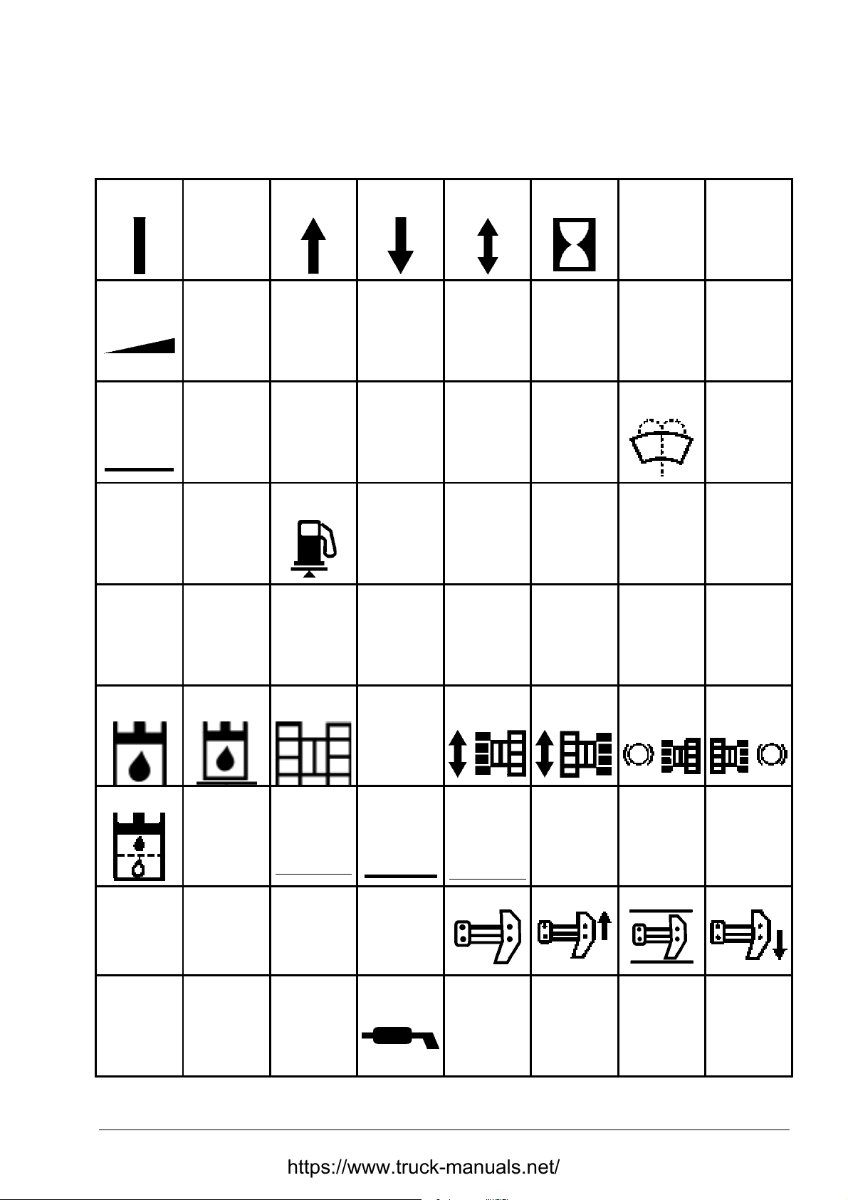
4.2. UNIVERSAL SYMBOLS FOR INSTRUMENTS AND CONTROLS
The use of universal symbols will pictorially identify various instruments and controls. These
symbols are an effort to overcome lang uage differences for all operators in a positive way, thus
enhancing their safety through quick er recognition of the instruments and contr ols while operating
the equipment.
Study the following symbols so you will know their meaning immediately and at a glance.
TD-25H DRESSTA
Page 43
OPERATING SECTION 4
Page 5
UNIVERSAL SYMBOLS FOR INSTRUMENTS AND CONTROLS
The bellow symbols are used in crawler dozers, however, not all of them must be used on this
machine.
ON
(GENERAL)
Variable slide
CONTROL
OFF
(GENERAL)
Variable rotation
CONTROL
FWD or UP REVERSE
Next speed
(straight-line)
or DOWN
Next speed
(rotation)
or REVERSE
NEUTRAL
position
2 1
Battery
switch
Horn Fuel filler Fuel level Air cleaner Coolant level
Oil pressure Starting aid
Voltmeter Lights
Drive train
oil filler
Dome
lights
Oil pressure Oil filler Oil level
Windshield
FWD
Wiper
HOURMETER
A/C
Rear window
wiper
Coolant
temperature
DANGER
WARNING
Electrical
receptacle
Window
washer
Engine
Oil
temperature
Caution high
pressure
Temperature
check
Fan
Engine RPM
Oil pressure
diagnostic point
Hydraulic
oil filler
Hydraulic filter Blade Raise Hold Lower Float Left Tilt Right Tilt
Left Angle Right Angle
FWD Pitch AFT Pitch
Hydraulic
oil level
Undercarriage
FWD Pitch AFT Pitch
Coolant filler
Vehicle FWD
or REVERSE
Grease
Lubricant
LH Track
driven
Ripper Raise Hold Lower
Engine
Start
RH Track
driven
Parking Brake
RH Track
brake
Brake ON
LH Track
brake
Lift or lift point
Fig. 4.1. Universal Symbols for Instruments and Controls
DRESSTA TD-25H
Page 44
SECTION 4 OPERATING
Page 6
4.3. INSTRUMENT PANEL
General
This section covers the location and function of the various instruments and controls. More
detailed information reg arding operation of controls can be found in the following text within t his
section. Regardless of previous experience as an operator; you must be thoroughly familiar with
the location and use of all instruments and controls before operating a machine.
CAUTION! Understand all control functions before starti ng t he engi ne.
IMPORTANT: After starting and while operating observe instruments and warning lights
frequently.
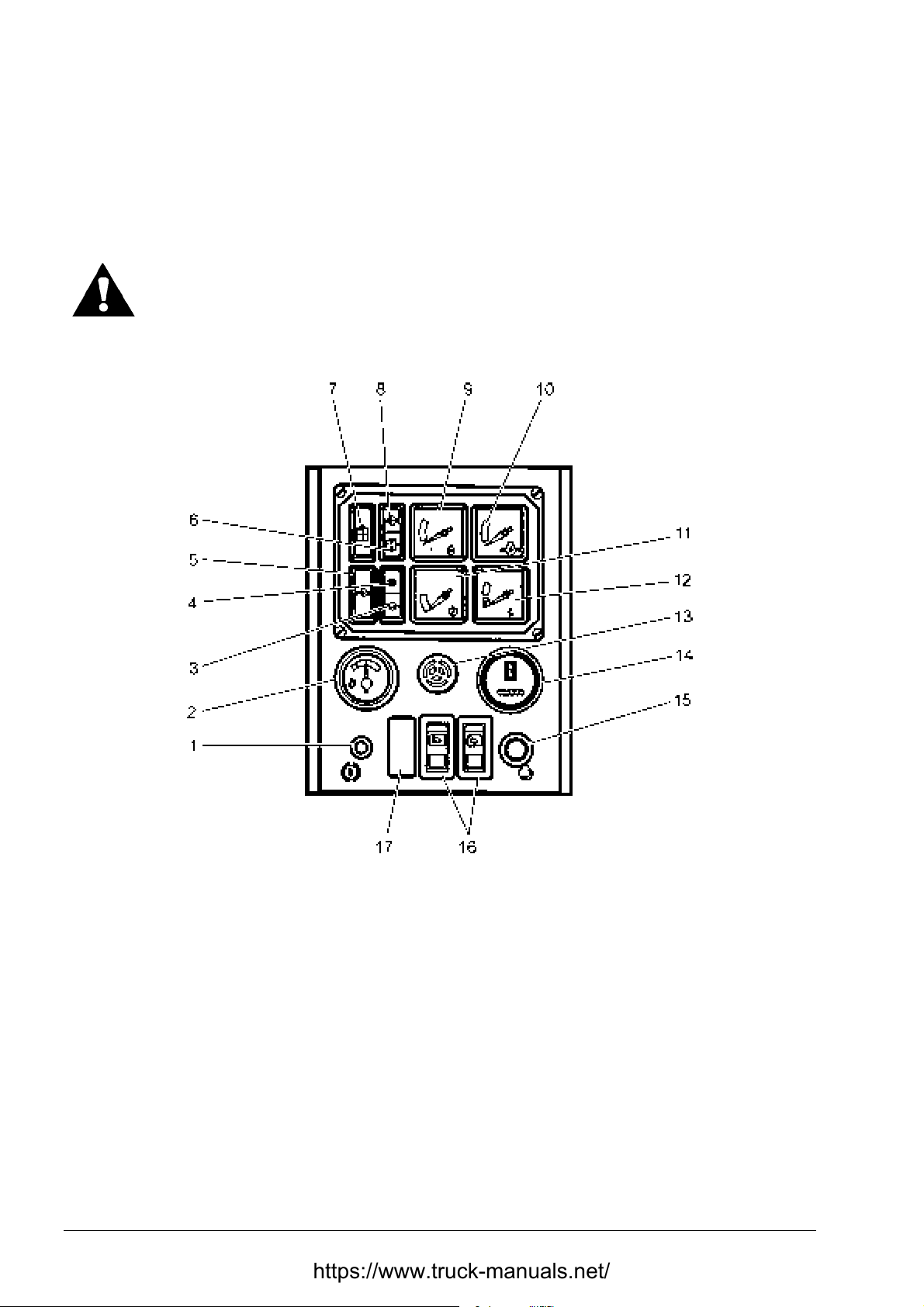
Fig. 4.2. Instrument Panel
1. Brake Lock
2. Fuel Level Gauge
3. Engine Coolant Level Warning Light
4. Air Cleaner Filter Warning Light
5. Low Engine Oil Pressure Warning Light
6. Transmission Oil Pressure Filters Warning Light
7. Hydraulic Oil Filters Warning Light
8. Transmission Main Low Oil Pressure and Clutch Low Oil Pressure Warning Light
9. Engine Coolant Temperature Gauge
10. Engine Oil Pressure Gauge
11. Torque Converter Oil Temperature Gauge
12. Voltmeter
13. Engine Coolant Low Level and Engine Low Oil Pressure Alarm
14. Hourmeter
15. Starting Button and Warning Light Check
16. Lights Switches
17. Ether Injector Switch
TD-25H DRESSTA
Page 45

OPERATING SECTION 4
Page 7
INSTRUMENT PANEL
1. BRAKE LOCK
This handle locks the brake and decelerat or pedal in the applied position f or park ing the machine.
To lock the brake and decelerator pedal, fully depress the pedal, pull out the lock handle and
remove your foot from the pedal. T o release the brake, simultaneously depress the brake pedal
and push in the lock handle.
2. FUEL LEVEL GAUGE
The gauge indicates quantity of fuel available for operation in t he fuel tank.
3. ENGINE COOLANT LEVEL WARNING LIGHT
The engine coolant level indicator will glow, if coolant level drops below the operating level. This
light is supplemental to low engine coolant and oil pressure alar m (13) on instrument panel.
4. AIR CLEANER FILTER WARNING LIGHT
The air cleaner filter warning light will glow amber when the filter element reaches the maximum
allowable restriction. When this happens, filter element service is required and examining the
problem. Refer to “AIR INTAKE SYSTEM”.
5. LOW ENGINE OIL PRESSURE WARNING LIGHT
The engine oil pressure warning light will glow and the audible alarm will sound when engine oil
pressure is low. When this happens stop the engine immediately and investigate the problem .
6. TRANSMISSION OIL PRESSURE FILTERS WARNING LIGHT
The transmission oil filter indicator will glow amber when one of the oil filter element reaches the
maximum allowable restriction. When this happens, transmission pressure filter change is
required.
7. HYDRAULIC OIL FILTERS WARNING LI GHT
The hydraulic oil filter warning light will glow amber when the oil filter element reaches the
maximum allowable restriction. When this happens, filter chang e is r e quired.
8. TRANSMISSION MAIN LOW PRESSURE AND CLUTCH LOW OIL PRESSURE WARNING
LIGHT
The transmission clutch low oil pressure warning light will glow when there is insufficient oil
pressure in neutral position or insufficient oil pressure available for the t ransmission clutches with
transmission in gear. When warning light is activated stop the engine and clean transmission
system suction filter and check oil level in rear frame. Refer to “TRANSMISSION SYSTEM” in
Section 5. If the light continues to glow stop the engine and consult Authorized Distributor of
Construction Equipment befor e operating the machine.
9. ENGINE COOLANT TEMPERATURE GAUGE
This gauge shows the temperature of the coolant circulating thr ough the engine. After t he engine
has operated a sufficient leng th of time, the pointer of the gauge must be in the GREEN area of
the gauge. During normal operation the gauge readings may vary between the minimum and
maximum indicated by the GREEN area of the gauge.
Continuous engine operating above the maximum temperature is harmful to the engine. Low
coolant temperatures will also cause exhaust smoke and increase the rat e of fuel consumption.
NOTE: In cold weather, if no louver is m ounted, it may be necessary t o cover part of the radiator
to maintain the minimum coolant tem perature indicated at the lower end of t he GREEN area.
The engine temperature under full load should remain in the GREEN of the gauge.
DRESSTA TD-25H
Page 46

SECTION 4 OPERATING
Page 8
INSTRUMENT PANEL
10. ENGINE OIL PRESSURE GAUGE
This gauge shows the pressure at which the lubricating oil is circulating through the engine. The
pointer must register in the GREEN area during operation of the engine. If the red light of the
gauge starts glowing stop t he engine immediately.
11. TORQUE CONVERT ER OIL TEMPERATURE GAUGE
This gauge shows the temperature of oil in the t orq ue converter . T he pointer of the gauge must be
in the GREEN area of the gaug e. If the point er is above the GREEN area of the g auge check the
following:
• whether the transmission is not in a gear rang e t oo high for the load handled,
• the oil level in the rear main fram e,
• the radiator for cleanness,
• suction filter for cleanness and suction line for leaks.
If the pointer still remains beyond the GREEN area, consult an Authorized Distributor of
Construction Equipment.
12. VOLTMETER
The voltmeter indicates the condition of the batteries. At low idle speed, the gaug e pointer should
be within the GREEN area with white stripe, which indicates a good battery charge. If the voltage
drops below this area, the batteries should be checked.
With the engine operating above low idle speed, the pointer should be within the upper GREEN
area, which is the normal operating range. If the pointer drops below or exceeds this area, the
battery, alternator or wiring may be at fault.
13. LOW ENGINE COOLANT AND LOW OIL PRESSURE ALARM
This alarm will sound when engine lubricating oil pressure or coolant level in the radiator drops
below normal. If so, stop the machine and f ind out which warning light g lows and check the gauge
indication.
14. HOURMETER
The hourmeter electrically records actual hours of engine oper ation. The pur pose of the hour meter
is to indicate when to perform the recommended maintenance and lubrication operations. The
hourmeter will register only when the engine is running.
15. STARTING AND WARNING LI GHTS CHECK BUTTON
The button is used to crank the engine.
IMPORTANT: To prevent damage to the starter motor and avoid low battery output, do not
continuously crank the engine for a period longer then 30-second. Allow 2 to 3 minute recovery
intervals between cranking.
Before starting the engine place the transmission neutral lock in neutral (OFF) and the electric
system master switch in the ON position. Depress the starting button and check if all warning
lights glow. If any warning light doesn’t glow that indicates that the bulb is def ective or it s circuit is
broken.
16. LIGHTS SWITCHES
The work light switches are the rocker type switches. W hen activated they t urn on the f ront and/or
the rear work lights.
17. ETHER INJECTOR SWITCH
This switch controls the ether injector for cold weather starting. Refer to “STARTING THE
ENGINE” for proper oper at ion of this switch.
TD-25H DRESSTA
Page 47
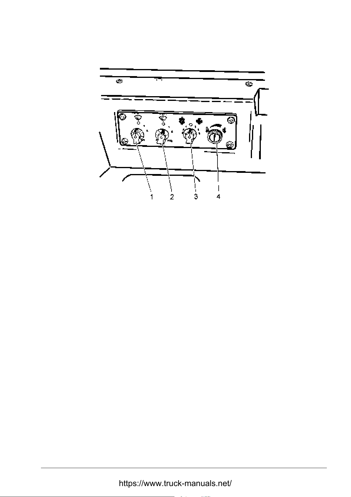
OPERATING SECTION 4
4.4. CAB CONTROLS
Page 9
Fig. 4.3. Air Conditioner, Heat er and Accessories Controls
1. Door Wipers Switch and Washer Push-button
2. Windows Wiper Switch and Washer Push-button
3. Heater and/or Cooler Pressurizer Control Switch
4. Temperature Control Knob
DOME LIGHT
Dome light is switched on with a switch mounted in the light.
CAB VENTILATION
NOTE: For maximum cooling t urn the temperature control knob f ully t o the left.
1. DOOR WIPERS SWITCH
This switch activates window wipers and washers. The switch enables two-speed selection of the
wipers that is: low (position 1) and high (position 2). Push the washer butt on to spray washer fluid.
2. WINDOW WIPERS SWITCH
This switch activates window wipers and washers. The switch enables two-speed selection of the
wipers that is: low (position 1) and high (position 2). Push the washer butt on to spray washer fluid.
3. HEATER AND/OR COOLING PRESSURIZER CONTROL SWITCH
This switch controls the speed of the fan circulating the air inside the cab. It has three speed
settings: low, medium and high. Turn the knob to the left for three fan speed selections when
cooling the air, i.e. low, medium and high.
Turn the knob to the rig ht for three fan speed selections when heating air i.e. low, medium and
high. To turn the fan off, turn the knob to the central position.
4. TEMPERATURE CONTROL KNOB
To supply cool air into the cab, turn the tem perature control k nob off (com pletely to lef t). The rate
of cooling can be adjusted by selection of fan speed as required.
To increase the temperature of the air, turn the t emperatur e control k nob to the rig ht. A tur n of the
knob opens the valve which lets more coolant through the heater and incr eases the temperature of
the air entering the cab.
DRESSTA TD-25H
Page 48
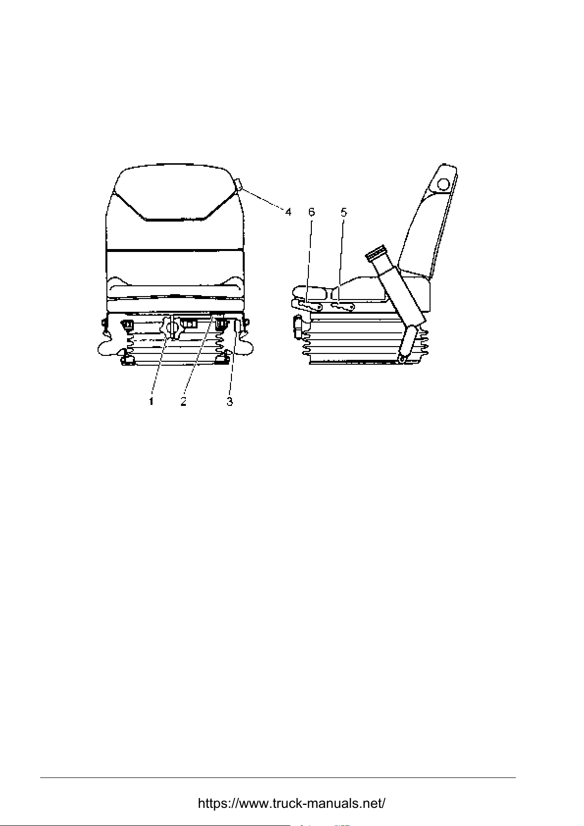
SECTION 4 OPERATING
Page 10
4.5. CONTROLS AND ADJUSTMENT
4.5.1. SEAT
SEAT ADJUSTMENT LEVERS
Fig. 4.4. Seat
1. Operator' s Weight Adjustment Knob
2. Seat Travel Lever
3. 15 [°] Swivel to Right Lever
4. Back Rest Profile Adjustment Knob
5. Back Cushion Tilt Lever
6. Seat Adjustment Lever
The operator’s seat is adjusted as follows:
Press tilt lever (5) to adjust the r equired angle of the back cushion.
Turn knob (1) to adjust to your own weight. Move lever (2) forward to slide the seat back or forth.
Turn knob (4) located on the left side of the back rest t o adjust the back rest prof ile.
For ripping operations lift lever ( 3) to swivel the seat 15[°] to the right.
TD-25H DRESSTA
Page 49
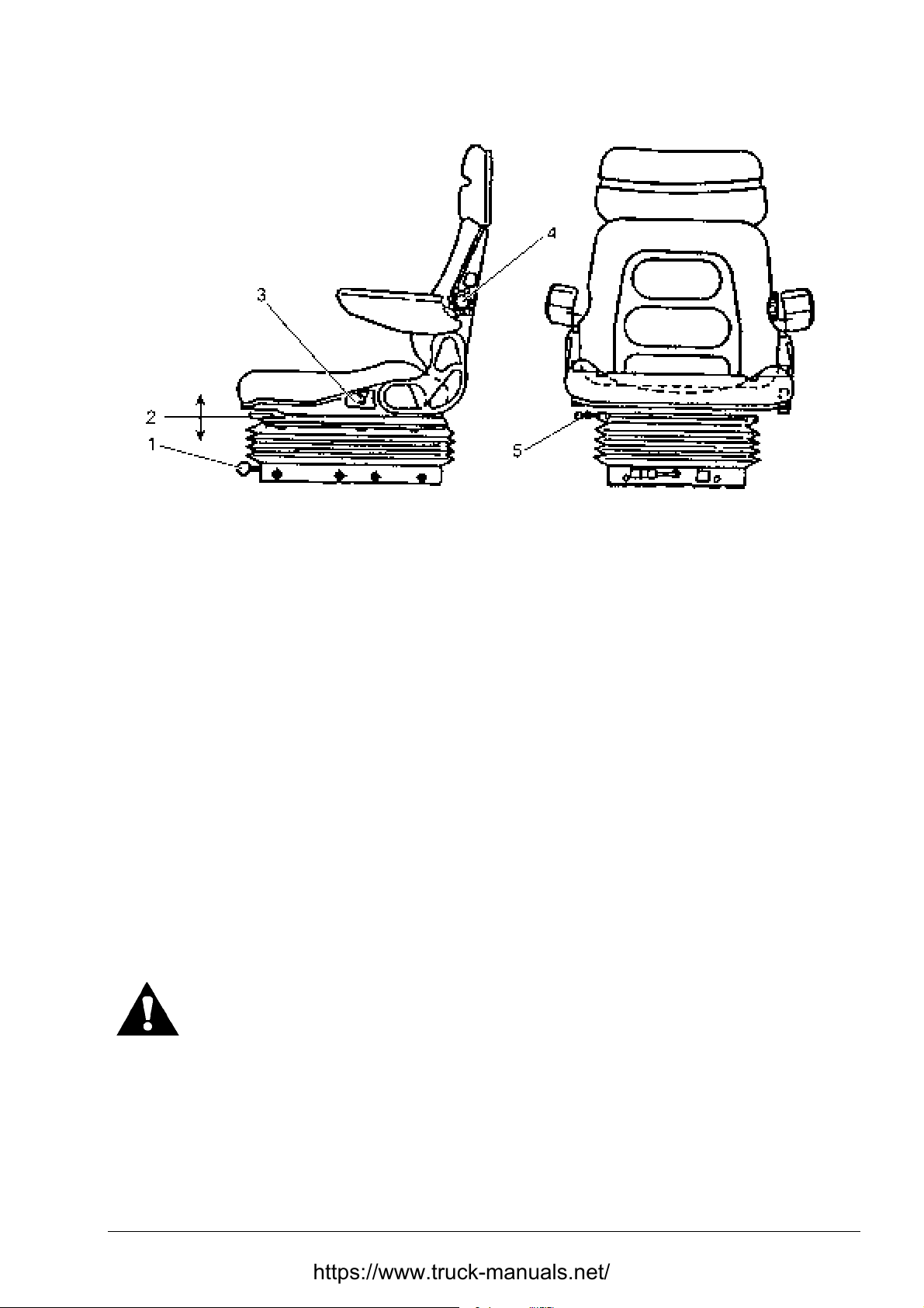
OPERATING SECTION 4
CONTROLS AND ADJUSTMENT
Fig. 4.4A. GRAMMER Seat (if equipped)
1. Operator's Weight Adjustment Lever
2. Seat Height Adjustment Lever
3. Back Rest Angle Adjustment Lever
4. Back Rest Profile Adjustment Knob
5. Seat Travel Lever
Page 11
This is a suspension seat with several adjustments to provide maximum comf or t to the operator.
Set with lever (1) the initial load according to t he oper ator's weight.
The seat cushion can be set in one of the f ollowing three posit ions: " low", "medium " and "hig h". T o
change the position press the cushion down or lift it up as necessary.
Turn knob (4) to adjust t he backrest profile.
Pull lever (5) forward and slide the seat forward or rearward to the desired positions and lock with
the lever.
The backrest angle can be adjust ed with lever (3).
The seat is equipped with arm rests and safet y belt. T he seat belt is the emerg ency t ype and does
not need to be adjusted.
4.5.2. SEAT BELT
WARNING! Before driving a machine adjust the seat and fasten the seat belt.
Adjust the belt to fit snugly and low around the hips to lessen the chance and
severity of injury in the event of an accident. Never wear the belt across the
abdomen.
DRESSTA TD-25H
Page 50
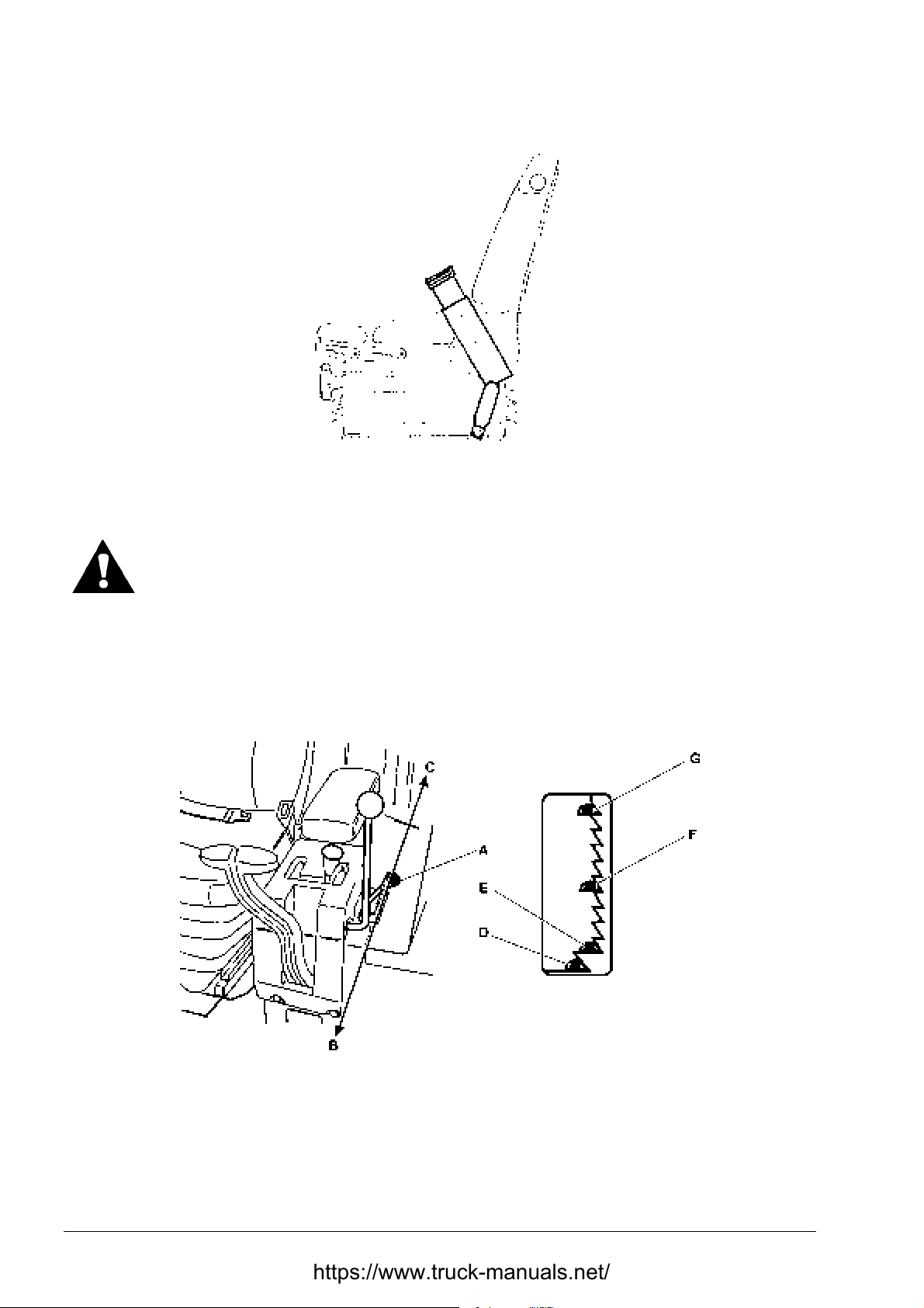
SECTION 4 OPERATING
Page 12
CONTROLS AND ADJUSTMENT
Fig. 4.5. Seat Belt
To buckle, insert the tong ue portion of the buckle into the lock ing portion.
WARNING! Do not use bleach, color dye or solvents on the seat belt webbing.
This may cause a severe loss of tensile strength. This could cause the webbing
to break resulting in personal injury.
It is recommended that the seat belt be cleaned only with warm water and a mild detergent.
Keep belt flat to avoid twisting and roping when not being used. Do not place heavy or sharp
object on the belt.
4.5.3. ENGINE SPEED AND SHUT DOWN LEVER
Fig. 4.6. Engine Speed and Shut Down Lever
A. Engine Speed and Shut Down Lever
B. Lever Forward to Decrease Speed
C. Lever Back to Increase Speed
D. Large Cutout for Engine Shut Down
TD-25H DRESSTA
E. Cutout for Engine Start and Low Idle Speed
F. Medium Idle Speed
G. High Idle Speed
Page 51
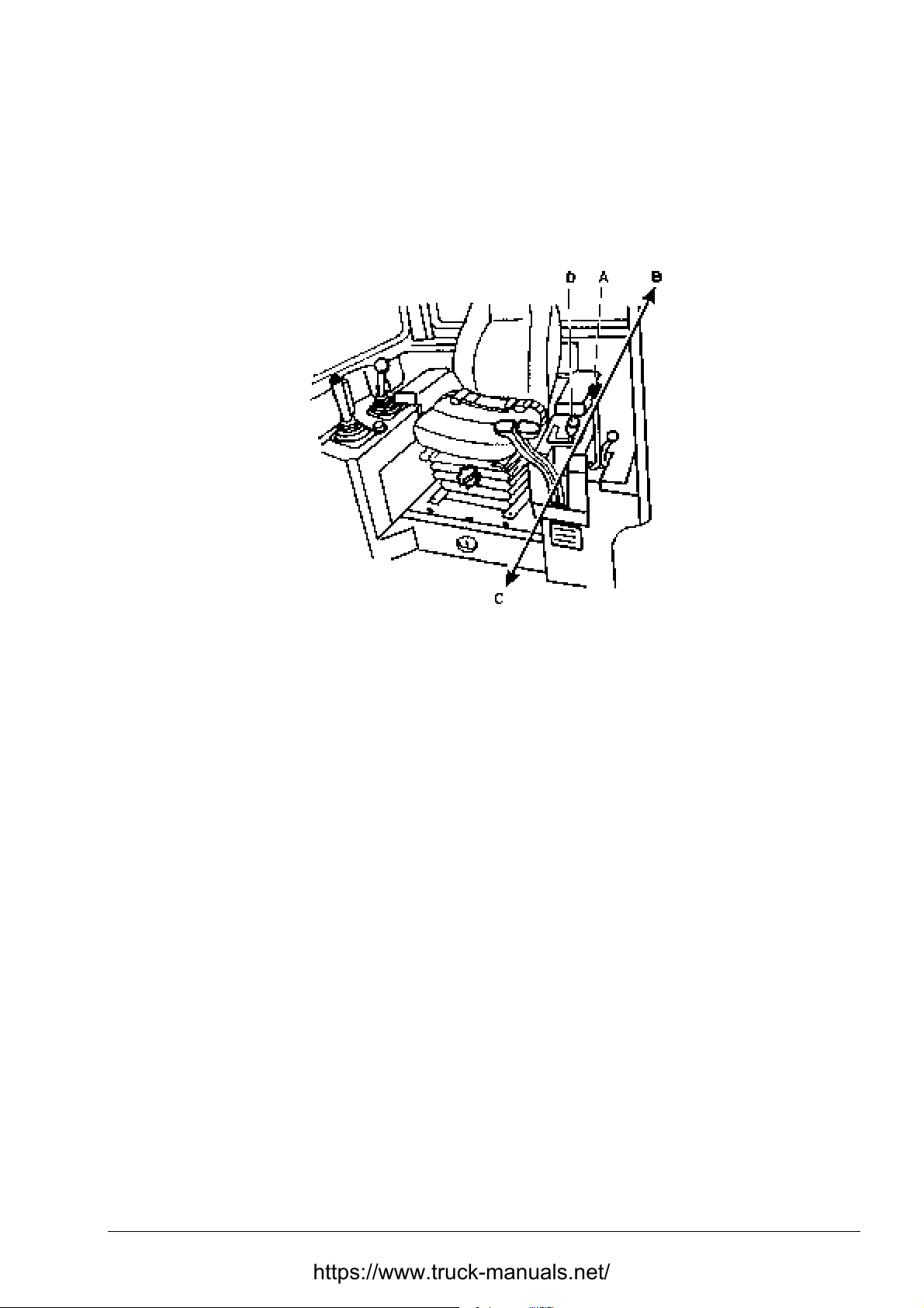
OPERATING SECTION 4
Page 13
CONTROLS AND ADJUSTMENT
This lever (A) is used to start the engine, cont rol speed of the engine or to shut it off . Push this
lever forward (B) to decrease engine speed. Pull the lever back (C) to increase engine speed.
Position lever in this large cutout (D) to shut down the eng ine.
4.5.4. TRANSMISSION NEUTRAL LOCK LEVER
Fig. 4.7. Transmission Neutr a l Lock Lever
A. Transmission Neutral Lock Lever C. Lever Forward to Release Shift Lever
B. Lever Rearward to Lock Shift Lever D. Transmission Shift Lever
This lever (A) is used to lock the transmission shift lever in “NEUTRAL.” Move the lever backward
(B) (ON position) to lock the shift lever, or f or ward (C) (O FF position) t o release. When starting t he
engine place the transmission shift lever in “NEUTRAL” and the transmission neutral lock lever in
the position (B) (ON).
4.5.5. TRANSMISSION SHIFT LEVER
Lever (D, Fig. 4.7) is used to select the various tr ansmission gear ranges and dir ectional ranges.
Refer to “SHIFTING THE TRANSMISSION – 4.10”
NOTE: When the shift lever is placed in one of the rever se positions, t he back-up alarm w ill sound
automatically.
DRESSTA TD-25H
Page 52
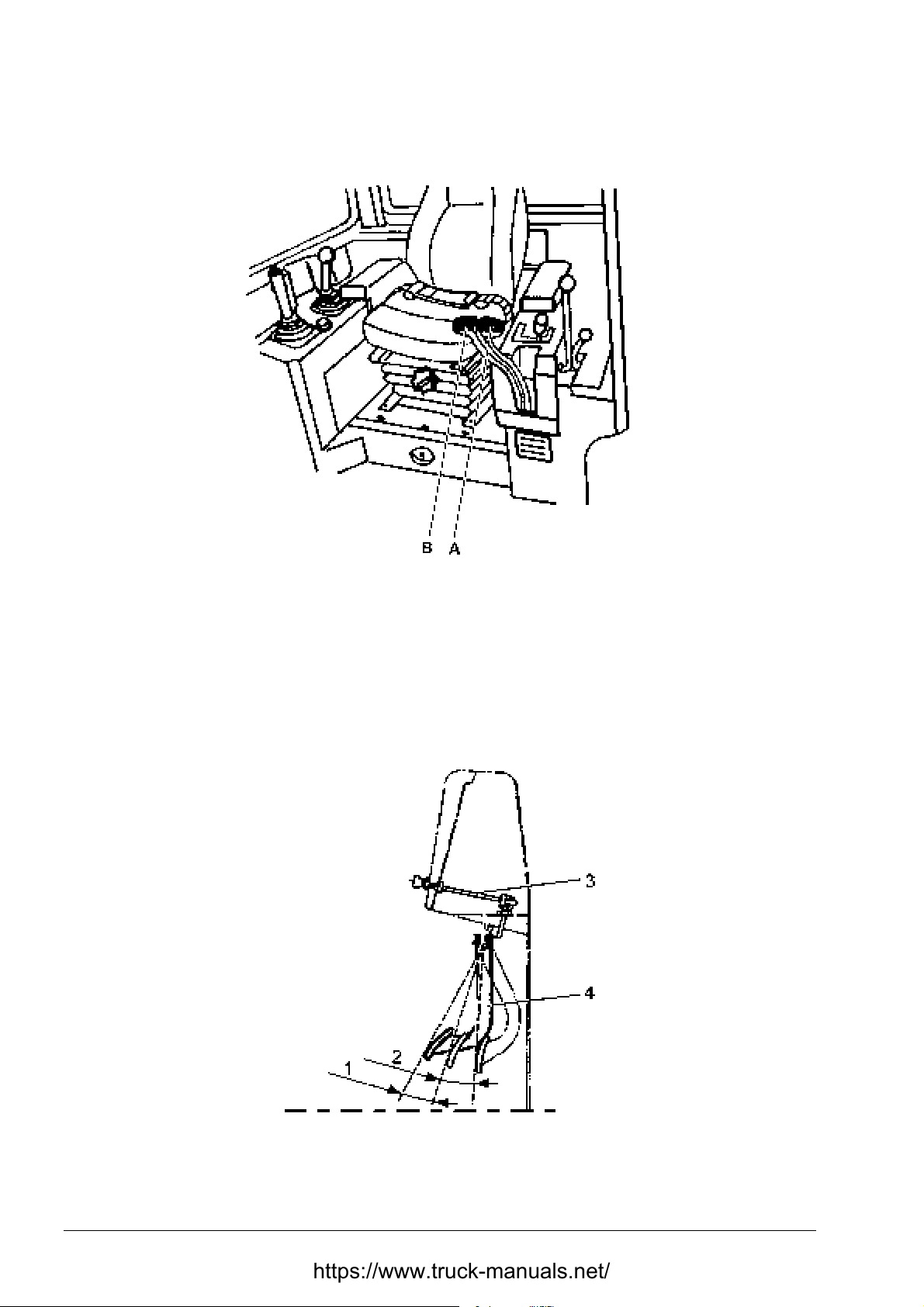
SECTION 4 OPERATING
Page 14
CONTROLS AND ADJUSTMENT
4.5.6. HAND STEERING LEVERS
Fig. 4.8. Hand Steering Levers
A. Left Hand Steering Lever B. Right Hand Steering Lever
These levers steer the machine by controlling engine power to the tracks and by applying and
releasing respective speed range clutch packs and brake clutch packs. The left hand steering
lever (A) controls the left track with the right hand steering lever (B) controlling the right track.
Refer to “STEERING THE MACHINE”.
4.5.7. BRAKE AND DECELERATOR PEDAL
Fig. 4.9. Brake and Decelerator Pedal Adjustment
1. Deceleration Angle (10 [°])
2. Braking Angle (14 [°])
TD-25H DRESSTA
3. Brake Lock Linkage
4. Brake and Decelerator Pedal
Page 53
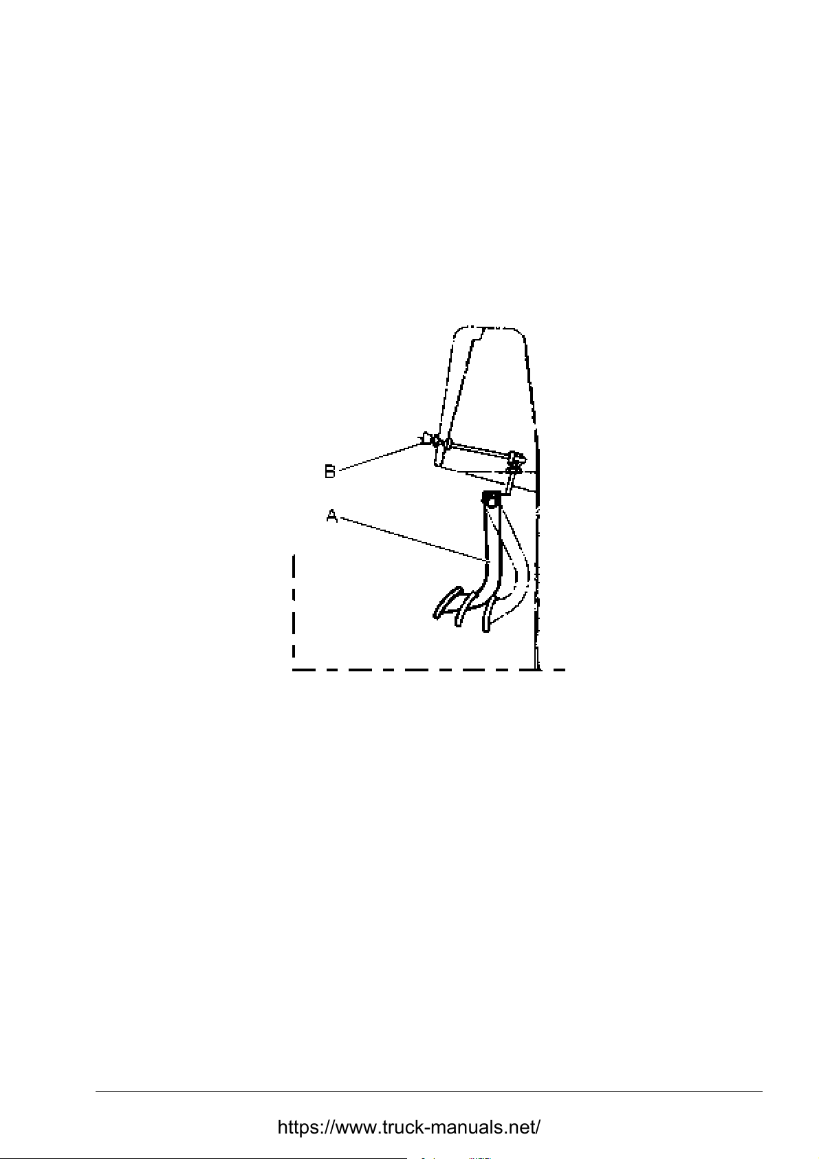
OPERATING SECTION 4
Page 15
CONTROLS AND ADJUSTMENT
This pedal overrides the engine speed control lever setting. Partial depression of the pedal
decreases engine speed for smoother chang es in machine direction and to ease the machine up
to a load. Release the pedal to accelerate the eng ine speed control lever setting . T his pedal stops
the machine when fully depressed. It also serves as a parking brake when the brake pedal lock is
applied and brake pedal lock knob is pulled out.
Periodic adjustment of the pedal m ight be required. If the adj ustment values are not within those
shown in Fig. 4.9 contact an Authorized Distributor of Construction Equipment.
4.5.8. BRAKE AND DECELERATOR PEDAL LOCK
Fig. 4.10. Brake and Decelerat o r Pedal and Lock
A. Brake and Decelerator Pedal
B. Brake Lock
This lock secures the brake and deceler ator pedal in the applied position for park ing a machine.
To lock the brake and decelerat or pedal fully depress t he pedal, pull out the lock and remove your
foot from the brake and decelerator pedal. To release the brake, depress the brake and
decelerator pedal and push the lock. Then r elease t he pedal.
IMPORTANT: Release the brake pedal lock before moving a machine. The brakes could bur n or
steering clutches be damaged if a machine is driven with par t ially applied br akes.
4.5.9. ELECTRIC SYSTEM MASTER SWITCH
Turn the key clockwise to connect the battery ground circuit. Turn the key counterclockwise to
disconnect the battery ground circuit.
IMPORTANT: Keep the switch on w hile the engine is running.
DRESSTA TD-25H
Page 54
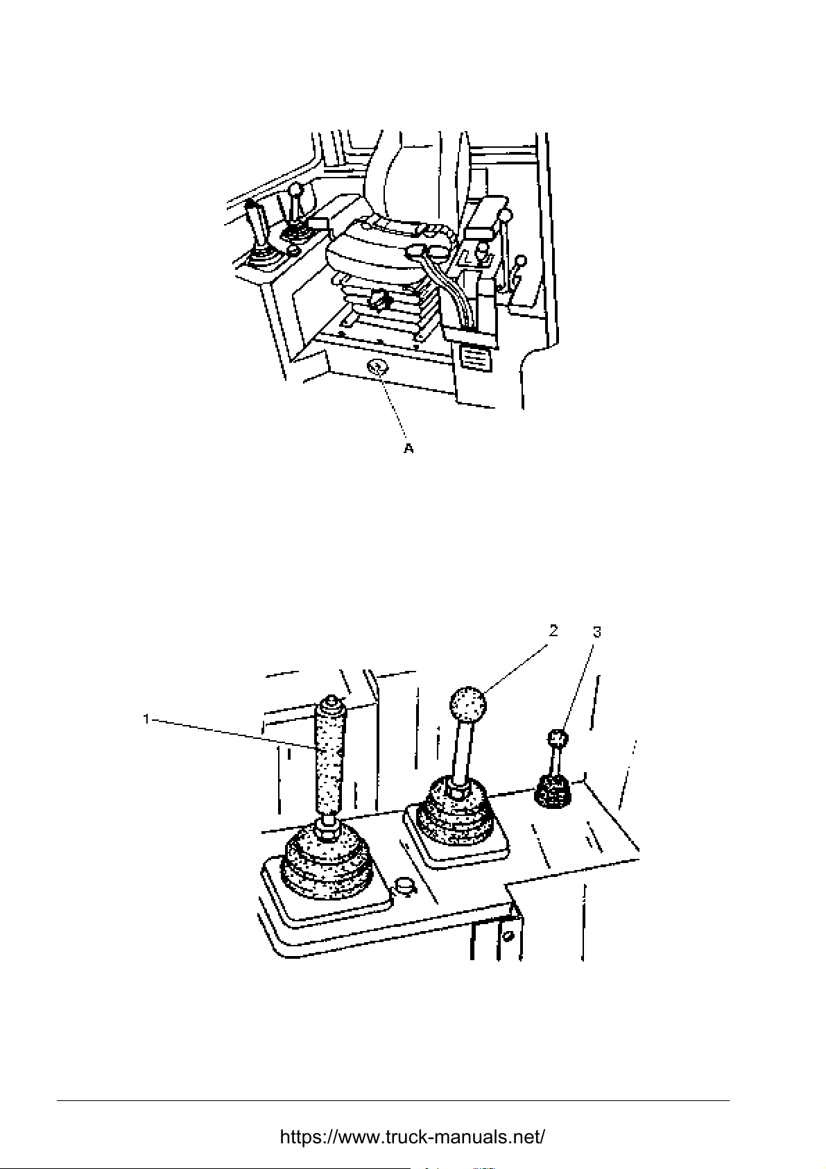
SECTION 4 OPERATING
Page 16
CONTROLS AND ADJUSTMENT
Fig. 4.11. Electric System Master Switch
A. Electric System Master Switch Key
4.5.10. EQUIPMENT CONTROL LEVERS
The levers are used to control the mounted equipment such as blade and/or ripper. Refer to
“OPERATING T HE MOUNT ED EQUIPMENT
Fig. 4.12. Equipment Control Lever
1. Blade Control Lever
2. Ripper Control Lever
3. Pin Puller Control Lever (if equipped)
TD-25H DRESSTA
Page 55
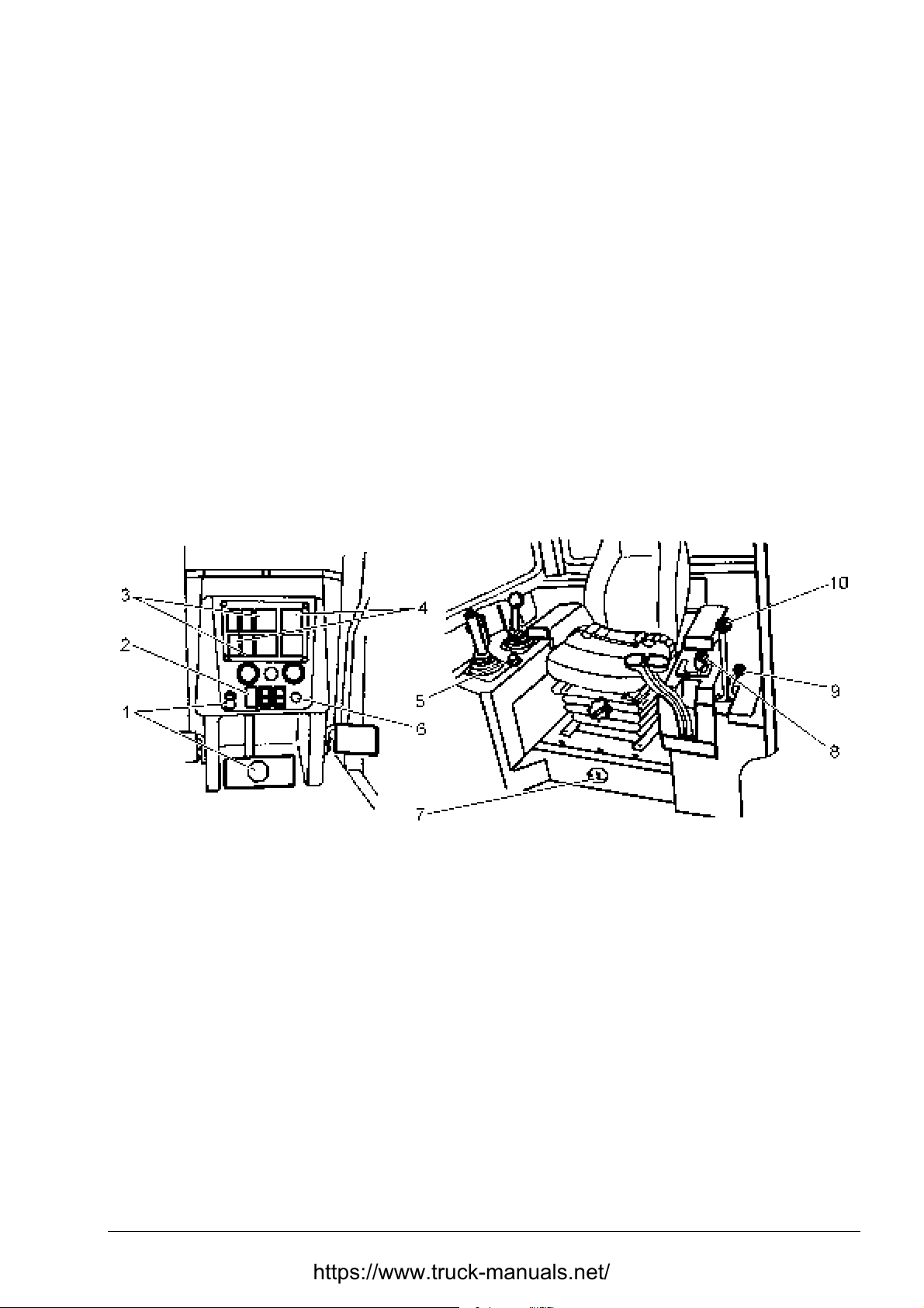
OPERATING SECTION 4
Page 17
CONTROLS AND ADJUSTMENT
BLADE CONTROL LEVER
The blade can be lifted or lowered, tilted or pitched by shifting the blade control lever to the
required position.
RIPPER CONTROL LEVER
The ripper can be lifted, lowered, or pitched by shifting the ripper control lever to the required
position.
PIN PULLER CONTROL LEVER (if equipped)
This lever controls installation or removal of t he pin secur ing the ripper shank in the tool beam.
NOTE: For proper control of the ripper control lever and observation of working tool swivel the
operator seat 15[°] to the right.
4.6. STARTING THE ENGINE
Fig. 4.13. Starting t he Engine
1. Brake and Decelerator Pedal and Brake Lock Knob
2. Ether Start Button
3. Engine Coolant Gauge and Light
4. Engine Oil Pressure Gauge and Light
5. Horn Button
6. Starting Button
7. Electric system Master Switch
8. Transmission Shift Lever
9. Engine Speed and Shut Down Lever
10. Transmission Neutral Lock Lever
IMPORTANT: Before operating a machine perform each of the 10 hour maintenance requirements
shown in Section 5.2., SCHEDULED MAINTENANCE. This engine cannot be started by towing,
pushing or coasting the machine.
DRESSTA TD-25H
Page 56
SECTION 4 OPERATING
Page 18
STARTING THE ENGINE
WARNING! Before entering the operator’s compartment, walk complet ely around
the machine and clear the area of personnel and obstructions.
CAUTION! Understand all control functions before starting the engine.
WARNING! Read all product graphics before starting, operating, maintaining, or
repairing a machine.
WARNING! Never start an engine indoors unless proper exhaust ventilation is
provided to remove deadly exhaust gases. Once the engine is running, move the
machine outdoors as soon as possible. Exhaust gases are hazardous and can
cause unconsciousness and death.
WARNING! Be sure all personnel are clear of the machine before starting the
engine. Sound the horn.
WARNING! Make sure the operator’s seat is adjusted properly and fasten the
safety seat belt.
4.6.1. NORMAL START (temperature above 0 [°C]) (Fig. 4.13)
1. Apply and lock the brake and decelerator pedal.
2. Place the transmission shift lever (8) in neut r al.
3. Place the transmission neutral lock lever (10) in vert ical “ON” position.
4. Move the engine speed and shut down lever (9) to low speed (idle) position E (Fig. 4.14).
5. Turn the electric system master ( 7) switch to “ O N” .
Fig . 4.14. Engine Speed and Shut Down Control Lever Positions
D. Large Cutout for Engine Shut Off
E. Cutout for Engine Start and Low Idle Speed G. High Idle Speed
TD-25H DRESSTA
F. Medium Engine Speed
Page 57

OPERATING SECTION 4
Page 19
STARTING THE ENGINE
6. Sound horn (5) to clear all personnel of the immediate area.
7. Crank the engine with button (6) .
IMPORTANT: Do not crank an engine for more than 30 seconds at a time. If the engine does not
start, allow the cranking motor to cool two or three minutes before cranking again.
8. Check the oil pressure. Stop the engine immediately, if the gauge fails to show the correct
pressure after 15 seconds.
9. Allow the engine to idle for 3 to 5 minutes (app.1000 [ RPM]) before increasing engine speed
and placing under load.
10. Check the indications of all instruments to ensure that the machine is operating correctly
Refer to “INSTRUMENT PANEL”.
IMPORTANT: It is not recommended to run the engine at low idle over 10 minutes due to
a possibility of increased wear of engine components.
4.6.2. ETHER INJECTOR START (temperatures below 0 [°C]) (Fig. 4.13).
WARNING! Ether starting fluid is highly flammable. Follow the precautions on
the container. An explosion can result if sparks or flame contact ether or when
storing an ether container when the air temperature is above 70 [°C].
Observe the following precauti ons:
• Do not use the ether injector when t he ai r temperature is above 0 [°C].
• Do not use open flame when using et her st art ing fluid.
• Do not store fluid containers in the operator's compart m ent .
• Store containers in a cool, well ventilated place.
• Keep fluid containers out reach of children.
• Do not breathe hazardous ether vapor.
• Do not let ether contact your skin, because it can cause frostbi t e.
• Never puncture a fluid container or put it into a fi re.
• Dispose of an empty container per instructions printed on the container.
• For your safety, remove the ether container when welding, gri nding, or usi ng a t orch on
a machine.
• Follow the correct method f or st art i ng t he engi ne.
• Before any attempt to start the engine, check the ether container or i nsure that a supply
of starting fluid is available under pressure and the system is in working condition.
Pressing the switch in the instrument panel makes ether injection.
IMPORTANT: The ether injector is to be used for engine starting only. Misuse of the ether
injector while the engine is running can result in a serious damage t o the engine.
1. Perf orm all steps as described in item s 1 throug h 6. Ref er to “NORMAL START” (temperat ure
above 0 [°C]).
2. Press the starting but ton (6) and during engine crank ing press the ether injector switch. Allow
one to two seconds for the chamber in the valve to fill then, with t he engine cranking , release
the ether injector switch to release a measured shot of starting fluid into t he engine.
DRESSTA TD-25H
Page 58
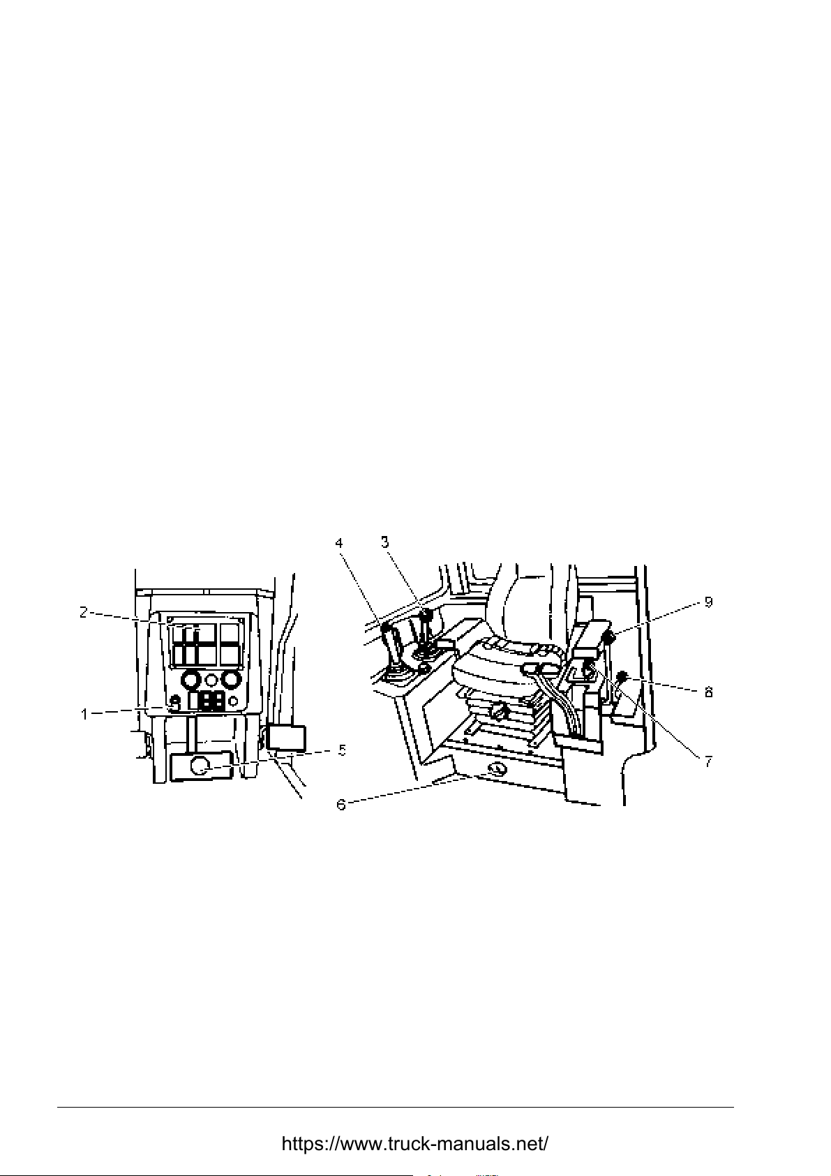
SECTION 4 OPERATING
Page 20
STARTING THE ENGINE
If the temperatur e is below –18 [°C], additional ether may be required. Allow a 10 second interval
between two successive injections. If the engine does not fire with a maximum of 4 injections,
determine the cause and correct befor e r est ar t ing the engine.
IMPORTANT: Do not crank an engine for more than 30 seconds at a time. If it does not start,
allow the cranking motor to cool tw o or t hr ee minutes before cranking again.
3. Perform steps from items 8 through 10. Refer to "NORMAL START"
4.6.3. ENGINE START AFTER OIL CHANGE OR PROLONGED STANDSTILL (over 5 days) (Fig. 4.13).
1. Perform all steps as described in items 1 through 3 and 5 through 6. Refer to “NORMAL
START”.
2. Place the engine speed and shut down lever in the OFF position (Fig. 4. 14) .
3. Press the engine starting butt on (6) on the instrument panel. Crank the engine until oil gauge
(4) registers oil pressure or the low oil pressure warning light goes off. Release the starting
button (6).
4. Move the engine speed and shut down lever to the idle position E (Fig. 4.14).
5. Perform all steps as described in item s 7 t h r ough 10. Refer to “NORMAL START”.
4.7. STOPPING THE ENGINE (Fig. 4.15)
Fig. 4.15. Stopping the Engine
1. Brake Lock Knob
2. Engine Coolant Temperature Gauge
3. Ripper Control Lever
4. Blade Control Lever
5. Brake and Decelerator Pedal
6. Electric System Master Switch
7. Transmission Shift Lever
8. Engine Speed and Shut Down Lever
9. Transmission Neutral Lock Lever
1. Using control levers (3 and 4) lower all mounted equipment to t he ground. Depress the brake
and decelerator pedal (5) and place the transmission shift lever (7) into NEUTRAL.
2. Apply the transmission neutral lock lever (9).
3. If the eng ine has been operated under load, operate it at idle speed f or 3 to 5 minutes to allow
the engine to cool down in a gradual and uniform manner.
IMPORTANT: Immediate engine shut-down after operation under load may result in engine
damage.
TD-25H DRESSTA
Page 59
OPERATING SECTION 4
Page 21
STOPPING THE ENGINE
4. Depress and lock brake and decelerator pedal ( 5) .
5. Move engine speed and shut down lever (8) to the large notched OFF position (Fig . 4. 14).
6. Turn the electric master switch (6) int o OFF position.
4.8. TIPS FOR ENGINE SAFEGUARDING
1. Do not operate the engine with the engine speed and shut down lever shifted into hig h speed
position, if the engine speed drops below the speed providing the maximal torque
(1400 [RPM] for N14-C350 engine fo r TD-25H dozer) for a period longer t han 30 seconds.
2. If the engine has been operat ed under load, operat e it at idle speed for 3 to 5 minutes to allow
the engine and the turbocharger t o cool down in a gr adual and uniform manner.
3. Do not put the engine under load before the coolant temper at ure grows up to 60 [°C] or it has
exceeded 100 [°C].
Do not operate the engine under load if t he coolant temperature is below 60 [°C].
4. If the coolant temper atur e reaches the m aximum perm issible level of 100 [°C] reduce the load
of the engine (either decrease the engine speed or reduce the gear or both) until it has
dropped down to the working range.
5. Stop the engine if the oil pr essure either drops below the minimum or grows above the
maximum the value of the working rang e.
6. Most malfunctions can be detected at an early stage. Observe any changes in engine
operation such as:
• uneven and intermittent operation,
• excessive vibrations,
• unusual engine drone,
• sudden changes of coolant temperatur e, or pressure
• excessive exhaust smoke,
• drop of the engine power,
• excessive oil consumption,
• excessive fuel consumption,
• oil, fuel or coolant leaks.
4.9. DRIVING THE MACHINE (Fig. 4.16)
CAUTION! Read the SAFETY PRECAUTIONS in Section 2 before operating
machine.
a
IMPORTANT: Before operating check all inst ruments.
WARNING! Never haul passengers. Only the operator should be on a machine
when it is moving.
WARNING! Sit in the operator's seat before operating the controls. Keep your
hands and footwear free of grease, water and mud to insure positive control
movements.
WARNING! Before operating a machine adjust the seat to allow full access to al l
controls and fasten the seat belt. Fail ure to do so could result in serious injuri es
or death.
DRESSTA TD-25H
Page 60
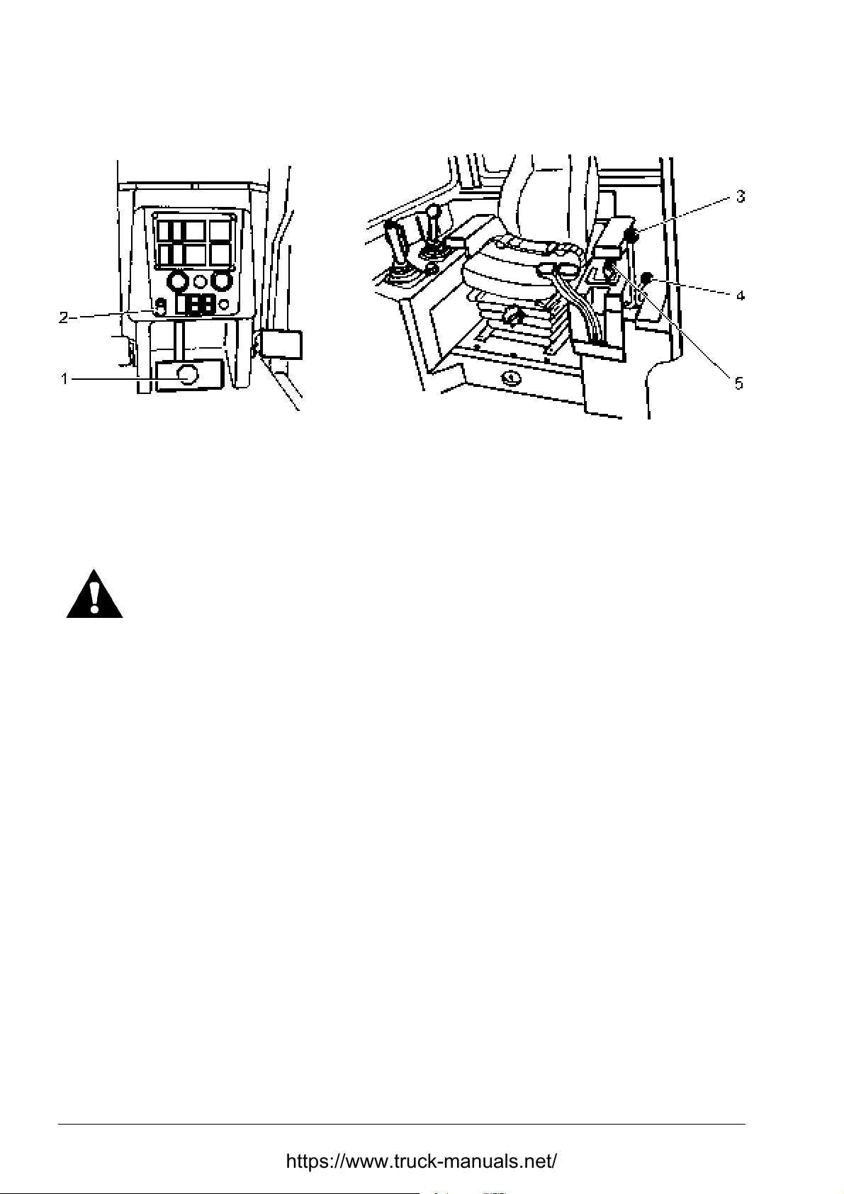
SECTION 4 OPERATING
Page 22
DRIVING THE MACHINE
Fig. 4.16. Driving the Machine
1. Brake and Decelerator Pedal
2. Brake Lock Knob
3. Transmission Neutral Lock Lever
4. Engine Speed and Shut Down Lever
5. Transmission Shift Lever
WARNING! Never get on or off a machine while it is moving because serious
injury or death could result.
1. Place engine speed and shut down control lever (4) in the high idle position ( G, Fig. 4.14).
2. Depress brake and decelerator pedal (1) t o decr ease engine speed.
3. Move forward transmission neutral lock lever (3) f r om ON to OFF position.
4. Place transmission shift lever (5) in the desired range. Refer to "SHIFTING THE
TRANSMISSION".
5. Gradually release brake and decelerator pedal (1) .
4.10. SHIFTING THE TRANSMISSION
Three speeds of the transmission, controlled by the transmission shift lever and the high and low
speed ranges of the steering drive, controlled by the steering levers provide six speeds for both
forward and reverse travel. W ith the steering levers in the low range and the transmission shift
lever in any speed position the machine can be put into second speed by moving the steering
levers into the high range. It is not necessary to stop the machine when shifting from one to
another gear range or f rom forward to reverse (or reverse to forward). Shif ting can be perf ormed
with the machine in motion.
TD-25H DRESSTA
Page 61
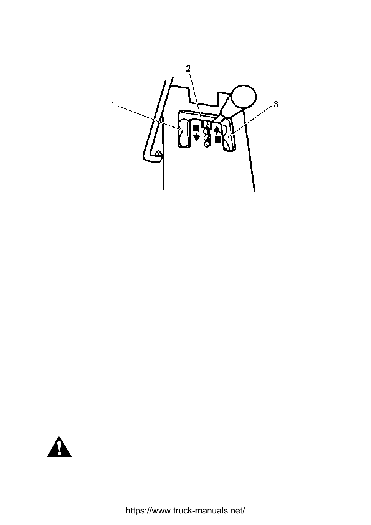
OPERATING SECTION 4
SHIFTING THE TRANSMISSION
Fig.4.17. Transmission Shift Lever Position
Page 23
1. Rear Gears
2. Neutral Position
3. Front Gears
4.11. CONVERTER OVERHEATING
If the pointer of the torque converter oil temperature gauge (refer to “INSTRUMENT PANEL"”)
moves out of the RUN area of the dial during operation, the transmission may be in a gear rang e
which is too high for the load. Shift down into the next lower gear range. The temperature should
reduce; if not, downshift again. I f the dial pointer remains out of the RUN rang e in the first gear,
stop the machine, shift into neutral and run the engine at 1000 [RPM] until the gauge pointer
moves into the RUN area.
If the converter remains overheated, stop the engine, check transmission oil level, clean the oil
radiator and the oil suction filter.
If the converter still rem ains overheated, stop the engine and consult an Authorized Distributor of
Construction Equipment befor e operating the machine.
4.12. STEERING THE MACHINE
Steering is accomplished with two steering levers. Each of the two levers functions in three
positions as shown in Fig. 4.18.
• in forward position A: transmits t he power to the track in the high rang e
• in middle position B: transmits the power to the track in the low range
• in rearward position C: disconnects the power and applies the brake
WARNING! Never pull both steering levers all the way back to stop a machine.
Use the foot brake (Brake & Decelerator Pedal) to slow down or stop the
machine.
DRESSTA TD-25H
Page 62

SECTION 4 OPERATING
Page 24
STEERING THE MACHINE
Fig. 4.18. Steering Levers
A. High Range B. Low Range C. Pivot Turn
4.12.1. GRADUAL TURN
To make a gradual left turn proceed as follows:
With the st eering lever in t he high rang e “A” move the LH st eering into t he low range “B”. W it h the
steering lever in the low range “B” move the RH steering into the high range “A”. When both
steering levers are in the low range, move the RH steering lever into the high rang e “A”. To mak e
a gradual right turn proceed in the similar manner.
4.12.2. PIVOT TURN
To make a pivot turn slow the machine down, then with both lever in either high “A” or low “B”
range pull the lever on the side toward which the turn is to be made all t he way back (posit ion “ C” ) .
4.13. DOWNGRADE OPERATION
WARNING! When operating a machine downhill, always put the transmission in
the low range position. Use the brake pedal to slow the machine. Never go
downhill with the transmission control in neutral. Failure to do so could result in
losing control of the machine and rollover could result.
Before going downgrade, select the range, which will provide full tractor control without
overspeeding the engine.
When going downhill control the speed of the machine using the brake and decelerator
NOTE:
pedal.
4.14. OPERATING OVER AN OBSTRUCTION
When crossing a log or ditch bank, use the decelerator pedal to slow the machine; and when
possible, cross at an angle. Then gradually increase the power to the tracks as the machine
moves forward, over, and down. If the load is light, it may also be necessary to use the brake
pedal to avoid abrupt movements.
TD-25H DRESSTA
Page 63
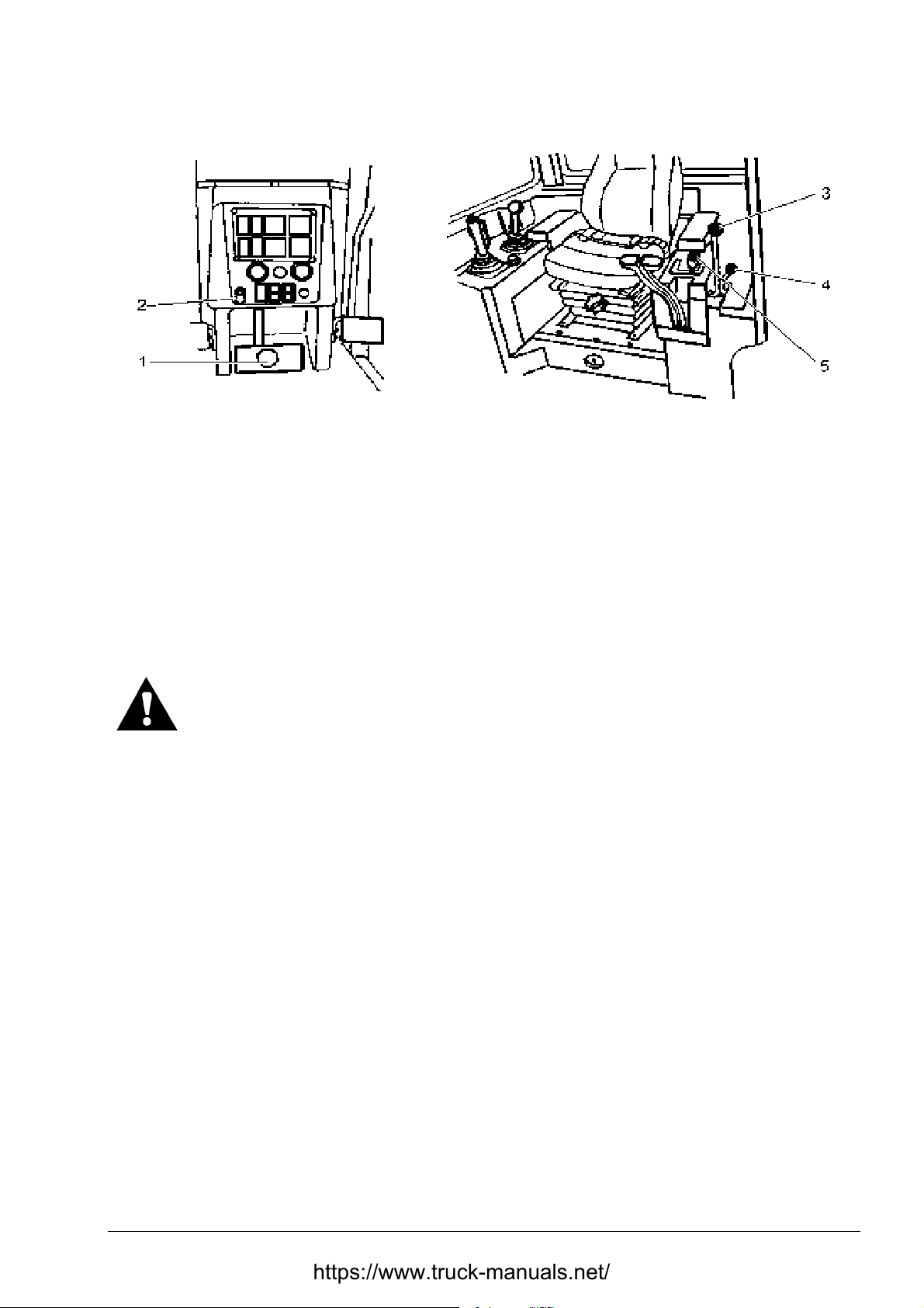
4.15. STOPPING THE MACHINE (Fig. 4.19)
Fig. 4.19. Stopping the Machine
1. Brake and Decelerator Pedal
2. Brake Lock Knob
3. Transmission Neutral Lock Lever
To stop a machine proceed as follows:
OPERATING SECTION 4
Page 25
4. Engine Speed and Shut-down Lever
5. Transmission Shift Lever
1. Depress the brake and decelerator pedal (1) unt il the machine is stopped.
2. Move the engine speed and shut down lever (4) to the low idle position (E, Fig. 4.14).
3. Place the transmission shift lever (5) in NEUTRAL.
4. Place the transmission neutral lock lever (3) in t he ON position (rearmost position).
5. Lock the brake and decelerator pedal ( 1) with the brake lock knob (2).
6. Lower the mounted equipment to the ground.
WARNING! Never leave a machine unattended with the engine running.
4.16. PARKING THE MACHINE
A few DO suggestions to prot ect both lives and equipment when parking.
DO park tractor on plank s in freezing weather to prevent the track s from freezing to t he ground.
DO lower the hydraulically operated tractor equipment to the ground and relieve the pressure in
the hydraulic system to reduce injury possibilities and to gain tractor stability.
Fig. 4.20. Parking on a Slope
DRESSTA TD-25H
Page 64

SECTION 4 OPERATING
Page 26
PARKING THE MACHINE
Parking on a slope is not recommended. Do park a tractor on a level ground, if at all possible to:
a) Avoid unexpected movement,
b) Obtain accurate coolant, lubr icant and fuel level checks.
Avoid parking on a slope because unexpected machine movement may occur. However,
if necessary, park at the right angle and secure the tracks with block s ( front and rear) (Fig. 4.20).
4.17. OPERATING MOUNTED EQUIPMENT
General
The hydraulic system provides power for the blade equipment, ripper or various other types of
equipment. Specific instructions for the operation of the blade and ripper are included in this
section.
IMPORTANT: Holding a control lever in any position except HOLD or FLOAT for an extended
period of time after the hydraulic cylinder rod has reached the limit of its travel will produce
excessive heat in the hydraulic system which may affect equipment performance.
4.17.1. BLADE CONTROL LEVER (Fig. 4.21)
Fig. 4.21. Blade Control Lever Positions (1)
1. Blade Control Lever
2. Ripper Control Lever
TD-25H DRESSTA
I. Lower
II. Hold
III. Raise
IV. Float
V . LH Tilt
VI. RH Tilt
Page 65
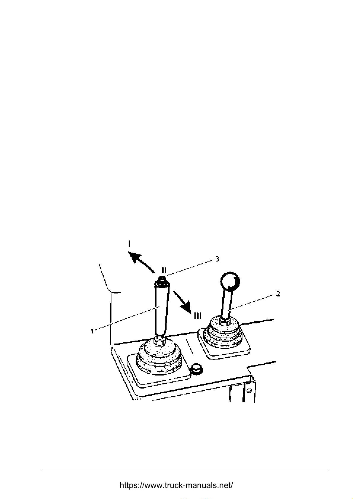
OPERATING SECTION 4
Page 27
OPERATING MOUNTED EQUIPMENT
4.17.1.1. HOLD
When the lever is released f rom any position except “Float”, the lever automat ically returns to the
“Hold” position. The blade height will remain t he sam e, as it was when the lever was released.
4.17.1.2. RAISE
Pull the control lever back (position III) to raise the blade to the desired height. When released the
lever will return to the “Hold” position.
4.17.1.3. LOWER
Push the control lever forward (position I) to lower the blade. When released the lever will return to
the “Hold” position.
4.17.1.4. FLOAT
With the cont rol lever in the “Float” position, the blade is f ree to follow the contour of the g round.
To place the control lever in the float position, push all the way forward to its det ented position IV
in Fig. 4.21. The lever will remain in this posit ion until it is manually returned to the “Hold” position.
Fig. 4.22. Blade Pitch Control Lever Posit ions ( 1)
1. Blade Control Lever
2. Ripper Control Lever
3. Pitch Button
DRESSTA TD-25H
I. Aft
II. Hold
III. Forward
Page 66
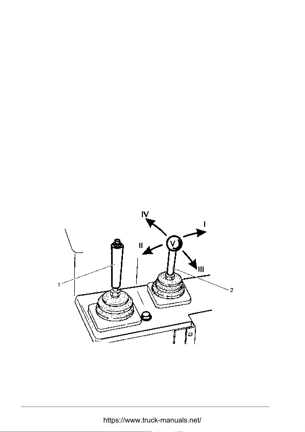
SECTION 4 OPERATING
Page 28
OPERATING MOUNTED EQUIPMENT
4.17.1.5. TILT
LH TILT
Pull the control lever to the left (posit ion V) to lower t he lef t- hand corner of the blade. The lever will
return to the “Hold” position when released.
RH TILT
Push the control lever to the right (position VI) to lower the right-hand corner of the blade. The
lever will return to the “Hold” position when released.
4.17.1.6. PITCH (FORWARD OR AFT) (Fig. 4.22)
1. To pitch the blade aft ( decreased angle of suction) depress button (3) and hold it down while
shifting the blade control lever to the right (position I). T he lever will return to the “Hold” position
when released.
2. To pitch the blade forward (increased angle of suction) depress button (3) and hold it down
while shifting the blade control lever to the left (position III). The lever will return to the “Hold”
position when released.
4.17.2. RIPPER CONTROL LEVER
NOTE: For proper operation of the ripper control lever and observation of working tool it is
necessary to swivel the operator’s seat 15 [°] to the r ight .
Fig. 4.23. Ripper Control Lever (2 )
1. Blade Control Lever
2. Ripper Control Lever
TD-25H DRESSTA
I. Shank Forward Pitch
II. Shank Aft Pitch
III. Ripper Raise
IV. Ripper Lower
V. Hold
Page 67
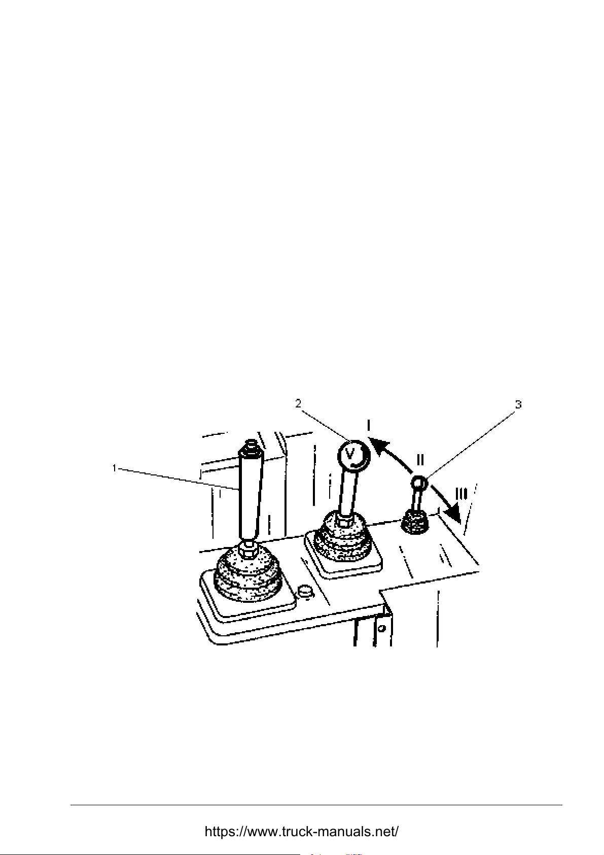
OPERATING SECTION 4
Page 29
OPERATING MOUNTED EQUIPMENT
4.17.2.1. SHANK PITCH (FORWARD OR AFT)
To pitch the ripper shank shift ripper control lever (2) as f ollows:
a. into position “I” to pitch the shank forward,
b. into position “II” to pitch t he shank aft,
The lever will return to the “Hold” position (“ V”) when released.
4.17.2.2. RIPPER RAISE AND LOWER
RIPPER RAISE
To raise the ripper to the required height, move the lever into position “III”. The control lever will
return automatically to HOLD position (“V”) when released.
RIPPER LOWER
To lower the ripper move the lever into position “IV”. The control lever will return automatically to
HOLD position (“V”) when released.
IMPORTANT: Holding the control lever in any position except HOLD for an extended period of
time will produce excessive heat in the hydraulic system w hich m ay af fect equipment performance
4.17.2.3. PIN PULLER CONTROL LEVER
Fig. 4.24. Pin Puller Control Lever ( 3)
1. Blade Control Lever
2. Ripper Control Lever
3. Pin Puller Control Lever
I. Pin Removal
II. Hold
III. Pin Installation
PIN REMOVAL
Push the control lever to the right, position “III” to remove the shank pin from the tool beam.
Simultaneous raising or pitching of the tooth will facilit ate the removal of t he pin. The control lever
will return automatically to the hold position when released.
DRESSTA TD-25H
Page 68
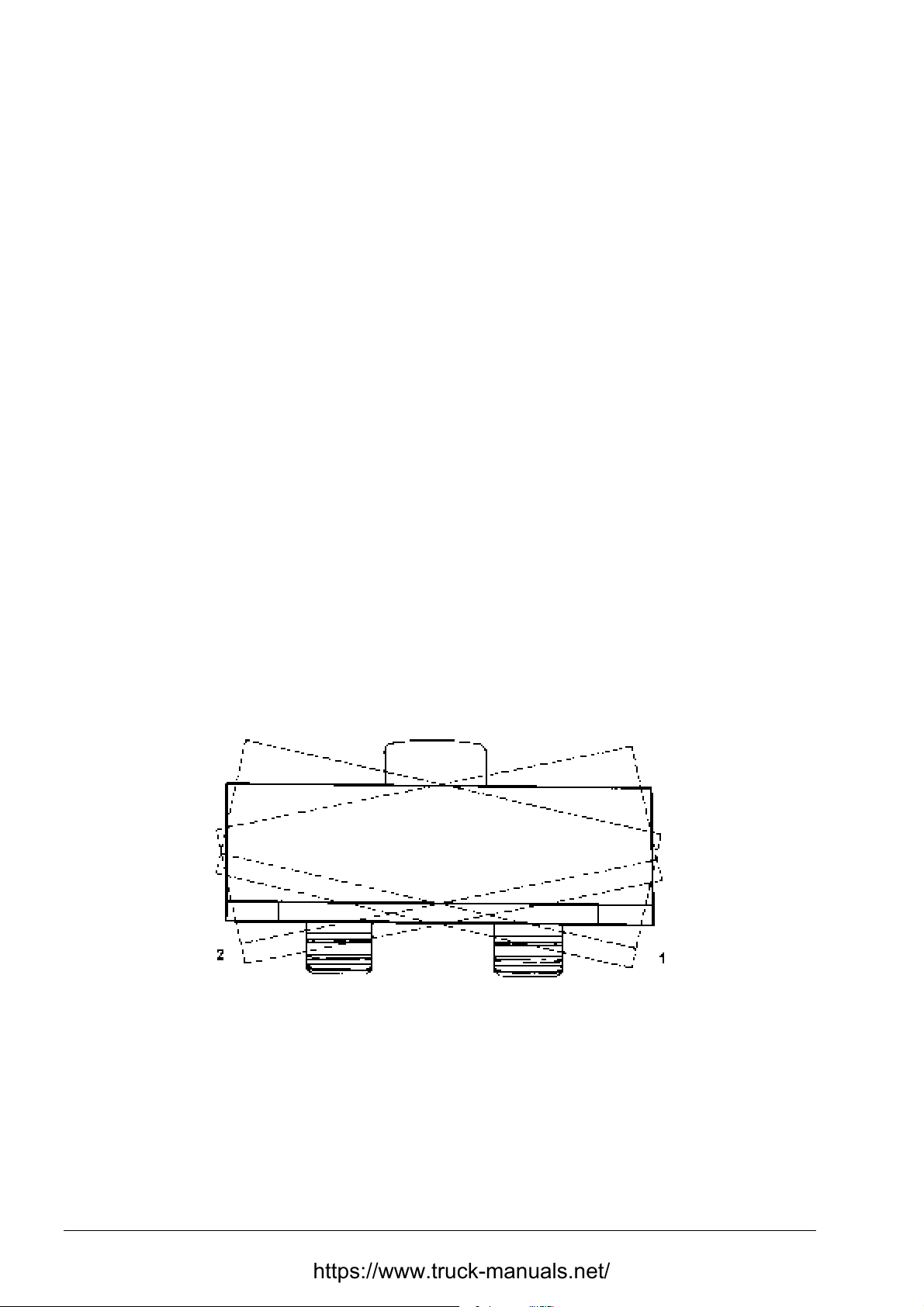
SECTION 4 OPERATING
Page 30
OPERATING MOUNTED EQUIPMENT
PIN INSTALLATION
Push the control lever to the left, posit ion “I” to install the shank pin into the shank mount ing hole.
Simultaneous raising or pitching of the tooth will facilitate the installation of the pin. The control
lever will return automatically to the hold position when released.
4.18. BLADE POSITIONS
4.18.1. BULLDOZER (D-2) BLADE POSITIONS
4.18.1.1. TILTING THE BLADE
TILTING THE BLADE WITH MECHANICAL TILT
1. Raise the blade above the ground and shut off the engine. Refer to “STOPPING THE
ENGINE”.
2. Remove the strut locking pin and adjust the upper strut on the side to be raised. Extend the
strut by the value equal approximately to half of required blade tilt.
IMPORTANT: Do not expose any portion of t he eyebolt t hreads.
3. Adjust the opposite side to get the desired tilt by shortening t he strut by the value equal to the
remaining part of desir ed tilt. Reinstall the locking pin.
Fig. 4.25. Blade tilt
1. RH Tilt 2. LH Tilt
TILTING THE BLADE WITH HYDRAULIC TILT
Proceed as follows:
1. Raise the blade off the ground.
2. Hold the tilt control lever in the tilt position on the side to which the blade is to be tilted until
the desired tilt is obtained. Maximum tilt is 500 [m m ].
TD-25H DRESSTA
Page 69
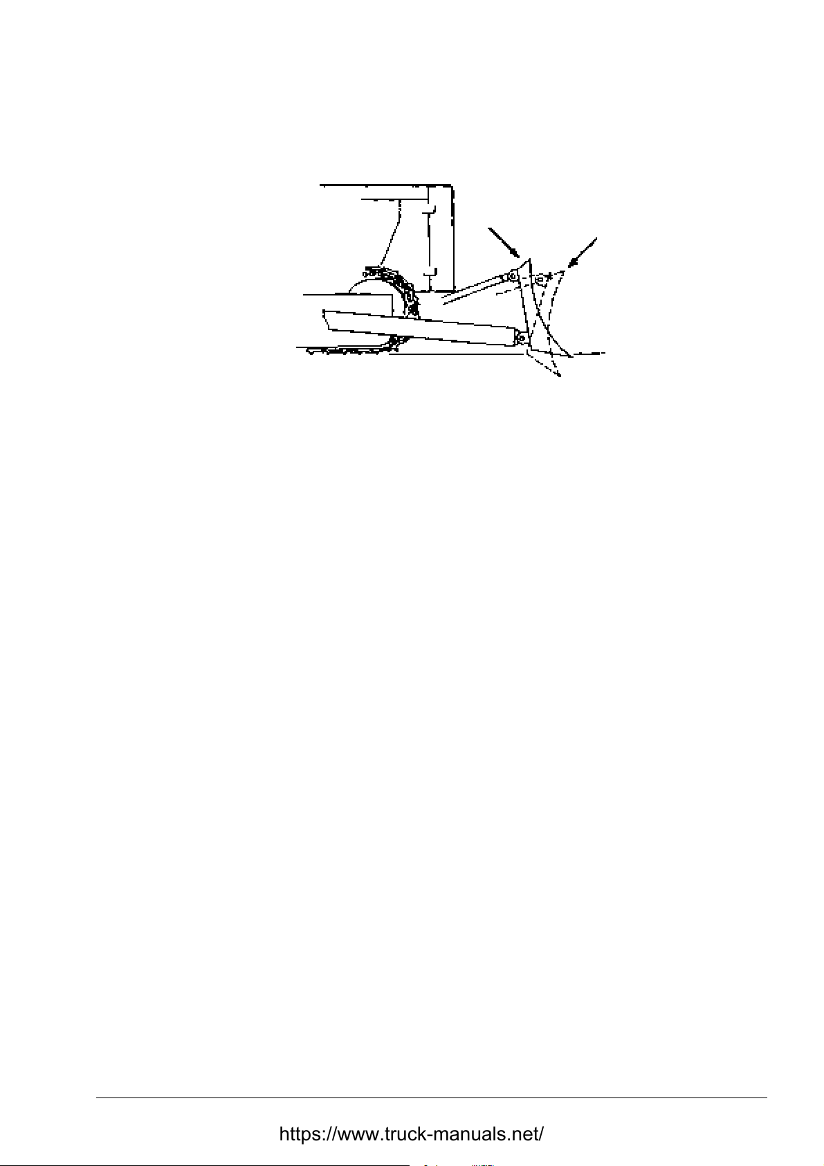
OPERATING SECTION 4
BLADE POSITIONS
4.18.1.2. PITCHING THE BLADE
Fig. 4.26. Blade Pitch
PITCHING THE BLADE (MECHANICAL PI TCH)
Page 31
1. To pitch the blade forward (increasing the suction ang le), raise t he blade several centimeter s of f the
ground. Shut off the engine. Ref er to „ST OPPING T HE ENGINE”. Then extend t he upper struts on
each side of the blade an equal amount.
IMPORTANT: Do not expose any portion of t he eyebolt t hreads.
2. To pitch the blade backward (decreasing t he suction ang le), the upper str uts must be short ened
on each side of the blade an equal amount.
NOTE: When the suction angle either increases or decreases the upper struts must be relatively
extended or shortened by the same value on both sides.
3. Aft er making the adjustment s, secur e the upper strut with the locking pin so it will not rota t e.
PITCHING THE BLADE ( HYDRAULI C PITCH)
1. T o pitch t he blade f orward (increasing t he suction ang le), raise the blade several cent imeter s of f t he
ground. Then depress button (3, Fig. 4. 22) and hold it down while shifting the blade control lever
to left (inwards) until the desired pit c h is obt ained.
2. To pitch the blade forward (decreasing the suction angle), raise the blade several centimeters off the
ground. Then depress button (3, Fig. 4. 22) and hold it down while shifting the blade control lever
to right (outwards) until the desir ed pitch is obtained.
Maximum pitch is 10 [°] (the difference between the minimum and maximum suction angle).
4.18.1.3. LEVELLING THE BLADE
LEVELLING THE BLADE WITH MECHANIC TILT ( Fig. 4.27)
1. Lift the blade a few centimeters off the ground. Stop the engine. Refer to „STOPPING THE
ENGINE”.
2. Remove locking pins. Adjust both upper struts so that the gap ("A") between the shoulder of
eye bolt (1) and strut body (2) is 35 [mm] . This will position the blade in its neut r al pitch position.
If the blade is not level a half rot a t ion of strut body (2) in either direct ion will level the blade.
DRESSTA TD-25H
Page 70

SECTION 4 OPERATING
Page 32
BLADE POSITIONS
3. Af ter the blade is level, raise the blade 300 [mm] off the ground. Adjust both struts to align t he
holes of the brackets and str u t s to allow installation of the mounting/ locking pins.
Fig. 4.27. Upper strut.
1. Strut Ball 3. Locking Pins
2. Strut Body 4. Eyebolt
LEVELLING THE BLADE WITH HYDRAULIC TILT
1. Place the lowest corner of the blade on a flat sur face.
2. Shift the control lever to the side to which the blade is to be lowered until the blade is even
along the flat surf ace.
NOTE: If the tilt cylinders are to be vented refer to “VENTING THE HYDRAULIC SYSTEM”,
section 5.
4.19. OPERATING TECHNIQUES
WARNING! Before operating a machine, be sure the area of the operator's
compartment, all mounting steps and grab handles are free of oil, grease, loose
objects, ice, snow and mud to lessen the possibility of slipping. Remove or
secure all maintenance and personal items so they will not interfere with the
operator or jam the controls. Failure to follow these instructions may result in
serious injury.
When the blade is held hydraulically, it becom es a rigid part of the t ractor, except when the valve
is in the “FLOAT” position, and will follow all movements of the machine. W hen rough terrain is
encountered it will be necessary to vary the height of t he blade while pitching to obtain a smooth
cut. W hen possible, start all jobs from a relatively level ground. If necessary, level an area large
enough to provide sufficient working space f or the machine. This prevents back and f orth pitch of
the machine and will result in easier digging.
TD-25H DRESSTA
Page 71
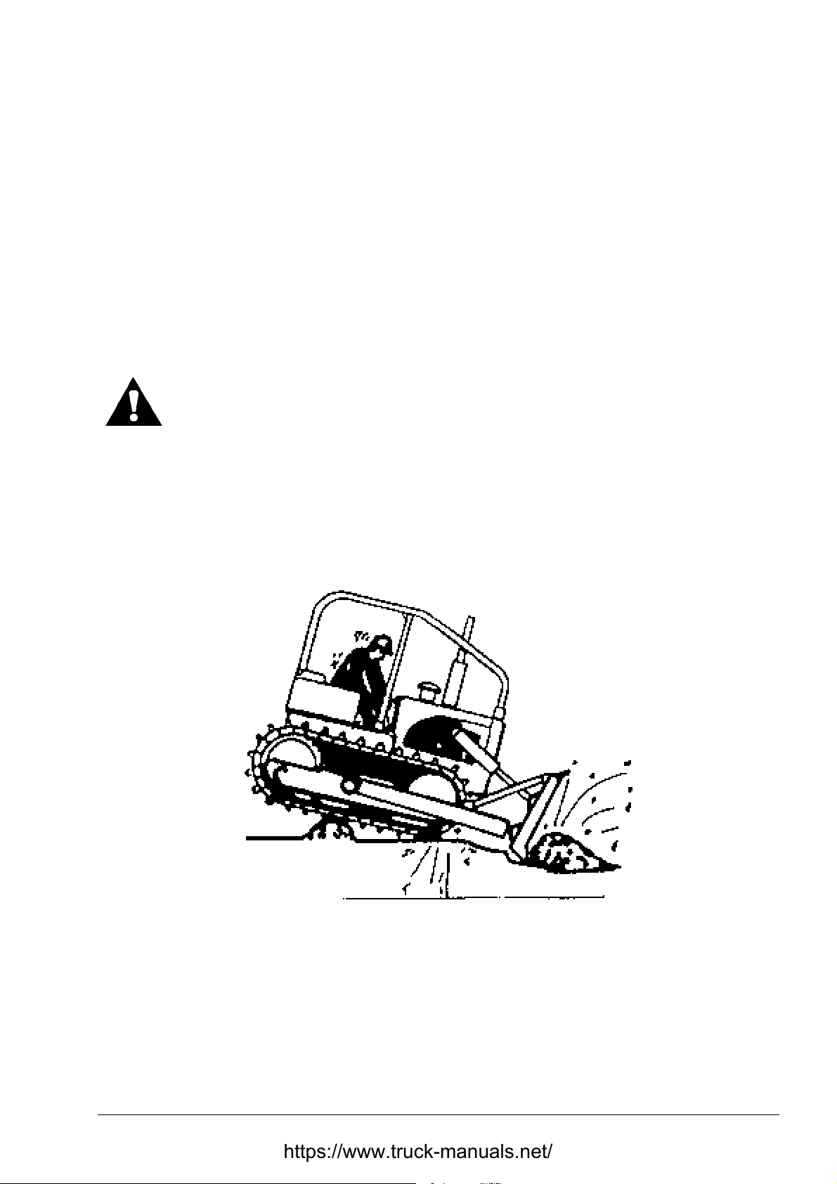
OPERATING SECTION 4
Page 33
OPERATING TECHNIQUES
Avoid track spinning whenever possible; this wastes effort and converts a relatively smooth
working area into ruts and piles that pitch and t ilt a t ract or. I n cold weather this mat erial can f reeze
and cause additional difficulty the f ollowing day.
Crossing ditches, ridges, r ock or logs should be done slowly and, at an angle. This slows the f all,
lessens the danger of upsetting the machine and reduces the f all jolt, which can be har mful to the
operator and the machine.
4.19.1. DIGGING AND CLEARING
WARNING! Prior to operating know the locations of gas lines, utility lines,
sewers, overhead and buried power lines, and the ot her obstructions or hazards
are known. A ruptured gas line or cut electrical line could result in personal
injury.
Always feed the blade into the ground gradually until t he desired depth of cut is obtained. W hen
selecting the gear range and det ermining the depth of cut, allow for an increase in resistance as
the load increases. W hen raising the blade at the end of a cut, do it gradually t o avoid an abrupt
ridge or bump in the path of the tractor. Move material downgrade whenever possible to take
advantage of the reduced effort required (Fig . 4.29).
Fig. 4.29. Moving Material Downgrade
Two methods of cutting down a pile or hill are shown in Fig. 4.30. Type of material and local
conditions may dictate which method is preferred. Further infor mation is included in “BREAKING
PILES AND SPREADING”. W hen using Method l never allow the high face t o become a hazard to
the operator or machine. With the tractor at the right angle to the face, raise the blade and
dislodge the high bank bef or e r eturning to the original direction of cut.
When using Method 2, m ake a cut wide enough to avoid trapping the tractor.
DRESSTA TD-25H
Page 72
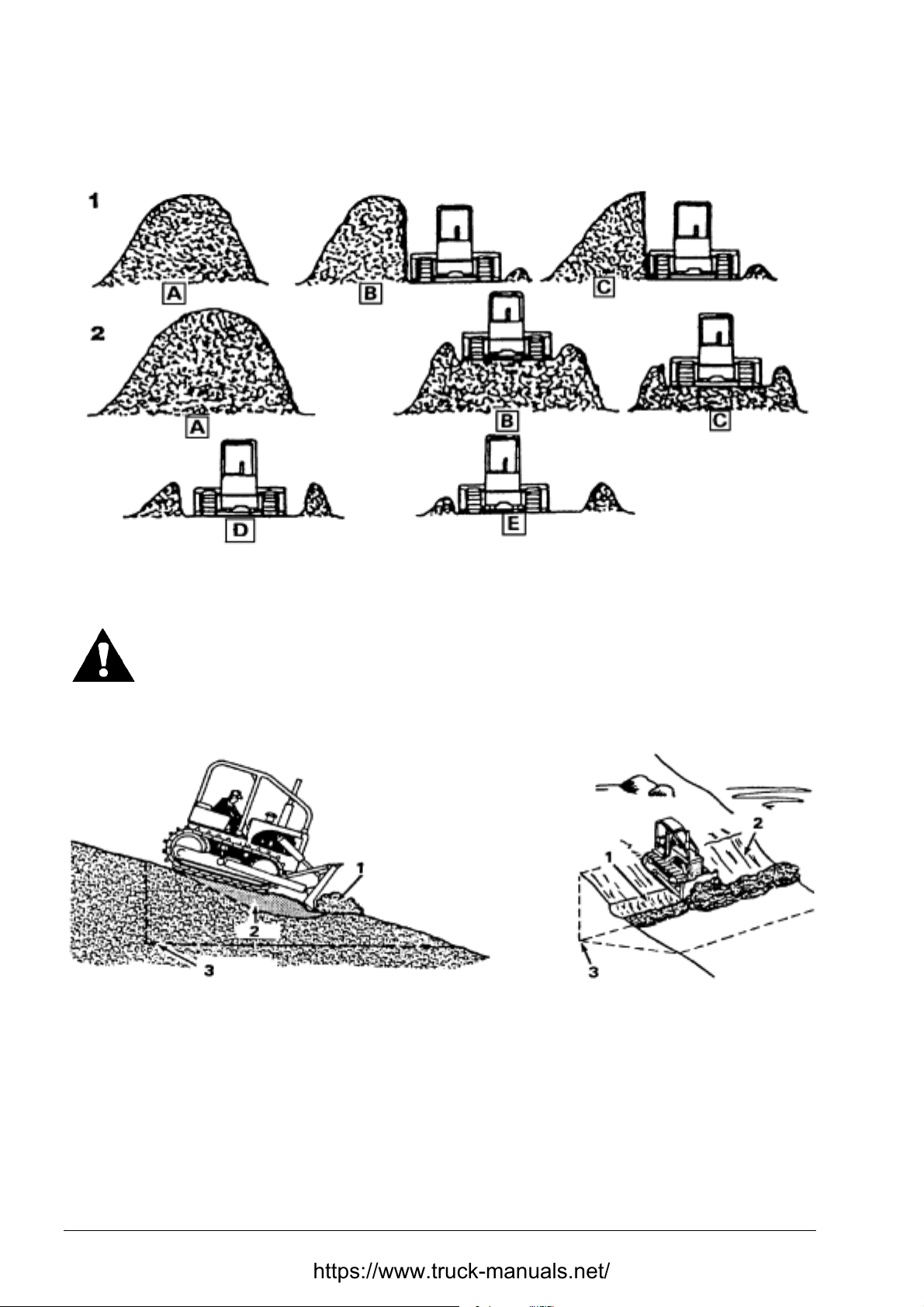
SECTION 4 OPERATING
Page 34
OPERATING TECHNIQUES
Fig. 4.30. Cutting Down a Pile or Hill
1. Method 1 2. Method 2
WARNING! Avoid high overhangs. Ramp up and remove the top layers first.
Avoid high banks. Operate the machine as far away from the trench as possibl e
or cave-in may result.
A hillside cut can be started more easily if a small bench cut is first made as shown in Fig. 4.31.
Fig. 4.31. Hillside Cut
1. Cut I 2. Cut II 3. Final level
Then, when digging as in Fig. 4. 32, keep the inside (uphill) surface slig htly lower to gain greater
tractor stability. Tilting the blade will provide this type of cut with less effort on the operator's part.
Always cut a shelf wide enough to provide solid support for equipment used later. If possible,
move the material downhill to gain the advantage of gravity, reduced eff ort and increased tractor
stability. Soft soil or shallow slopes may allow the side hill cut to be made as shown in Fig. 4.33.
Increased stability is realized by running the uphill track inside t he ridg e lef t by the f irst cut . Cut s 3,
4 and 5 illustrate the completion of t he shelf.
TD-25H DRESSTA
Page 73
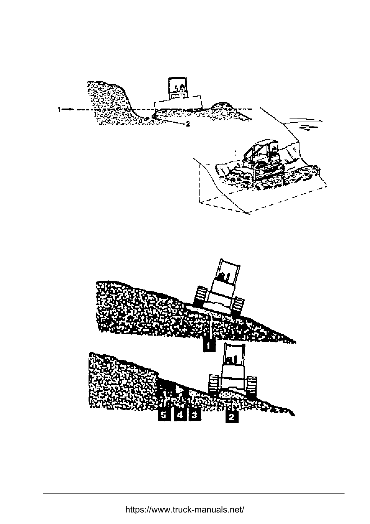
OPERATING SECTION 4
OPERATING TECHNIQUES
Page 35
Fig. 4.32. Hillside Cut
1. Level I 2. Lower Surface
Fig. 4.33. Shallow Slope Hillside Cut
Once again, pushing loosened material t o the lower side of the slope Fig . 4.34 will normally reduce
time and cost. Do not push material beyond the point required to retain firm t r ack support.
DRESSTA TD-25H
Page 74
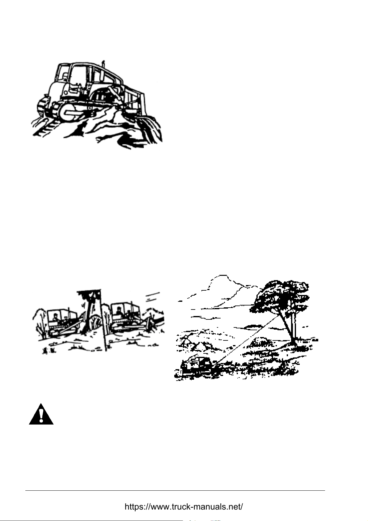
SECTION 4 OPERATING
Page 36
OPERATING TECHNIQUES
Fig. 4.34. Slope Edge Operat ion Fig. 4.35. Operating a Tandem Ar r angement
When backing up, do not raise the blade as this puts extra weight on the front idlers causing
greater track penet r at ion. Let the blade float as you back away from the edge of soft fills.
Initial work on steep hillsides can be safer by either secur ing the tractor with a winch to a suitable
uphill anchor point or by operating a tandem arrangement as shown in Fig. 4.35.
When clearing trees, raise the blade high to gain leverage and make contact gently to reduce
possible harm to the operator and machine (Fig. 4.36).
Heavy roots of large trees may requir e pushing and digging or cutting from several sides of the
tree. Use a cable to topple and remove trees from soft ground ( Fig. 4.37).
Fig. 4.36. Machine Equipped with Sweeps Fig. 4.37. Using Cable to Remove T rees
CAUTION! Falling trees and dead limbs can cause injuries. When cl earing trees,
operator protection must be used.
When clearing a rock y area, r emove the small and loose r ock s f irst, larg e and solid rock s can then
be loosened and moved with less difficulty. W hen loosening larg e or solid rock s, great er f orce and
penetration can be obtained by tilting the blade and prying under the rock with the lower edge of
the blade (Fig. 4.38). Lifting the rock with the blade while pushing will increase traction and r educe
track spinning.
TD-25H DRESSTA
Page 75
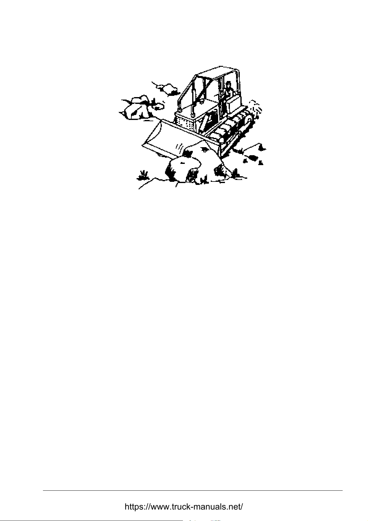
OPERATING SECTION 4
OPERATING TECHNIQUES
Fig. 4.38. Loosening Rocks with Lower Edge of the Blade
Page 37
Penetration on hard, frozen or rock y ground can be made easier by tilting t he blade. This will add
weight and power to the lower cutting edge. When the ground is frozen and the area must be
ripped before it can be worked, rip a relat ively small section and work it t o grade bef ore enlarging
the cut. This will require ripping each sect ion only once, not every morning after the ground has
refrozen. Snow can act as an insulating blanket and reduce or eliminate the need for a ripper.
Therefore, remove snow only from the area to be worked each day; leave the rest to insulate the
ground.
4.19.2. TRANSPORTING, PILING OR LOADING
Transporting of material with a bulldozer or bullgrader is not always a most economical method.
Natural ridges, a window formed by side blade spillage on earlier passes or side-by-side, dozing
will improve the productivity (Fig 4.39). Where the quantity of material or distance involved
becomes excessive, a loader, scraper or truck should be considered.
Fig. 4.39. Side-by-Side Dozing
DRESSTA TD-25H
Page 76
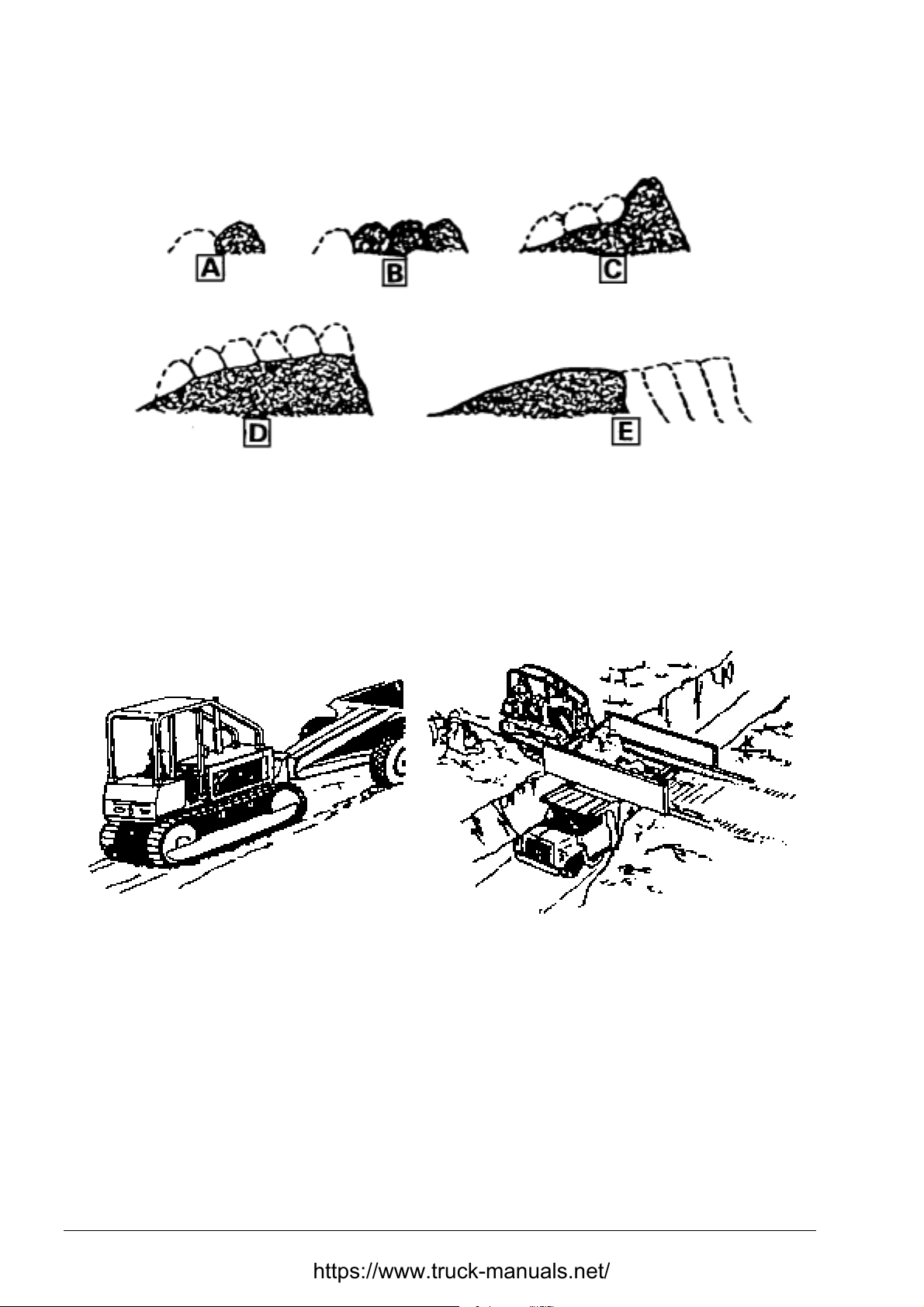
SECTION 4 OPERATING
Page 38
OPERATING TECHNIQUES
Fig. 4.40. A Usual Method of Piling
A usual method of piling is shown in fig. 4.40. When the piling reaches stages “D” or “E” the
operator may elect to continue one or the other depending on the height or area desired. W hen
the machine is used as a pusher, aiding scraper loading (Fig. 4.41), the machine power must be
carefully controlled. Excessive “push” eff ort can cause the scraper unit t o “j ackk nif e” , with result ing
injury or damage. On turns, be sure the blade of the pusher tractor does not com e in contact with
the rear wheels of the scraper.
Fig. 4.41. Aiding Scraper Loading Fig. 4.42. Loading Directly
A bulldozer can be used directly as a loader if the method shown in Fig. 4.42 is used.
4.19.3. BREAKING PILES AND SPREADING
Two methods of breaking down a pile are shown in Fig. 4.43. When spreading is to be done
in several directions or if the pile is larg e or hard, Method 1 is usually desired. When using Method
1, cut into the side of the pile f rom dif f erent angles. When Method 2 is used, and access to t he t op
of the pile is difficult, a slot may be started as shown below. Loosen the material at the base and
form a dirt “ramp” to provide a decreased angle of approach and cut.
TD-25H DRESSTA
Page 77
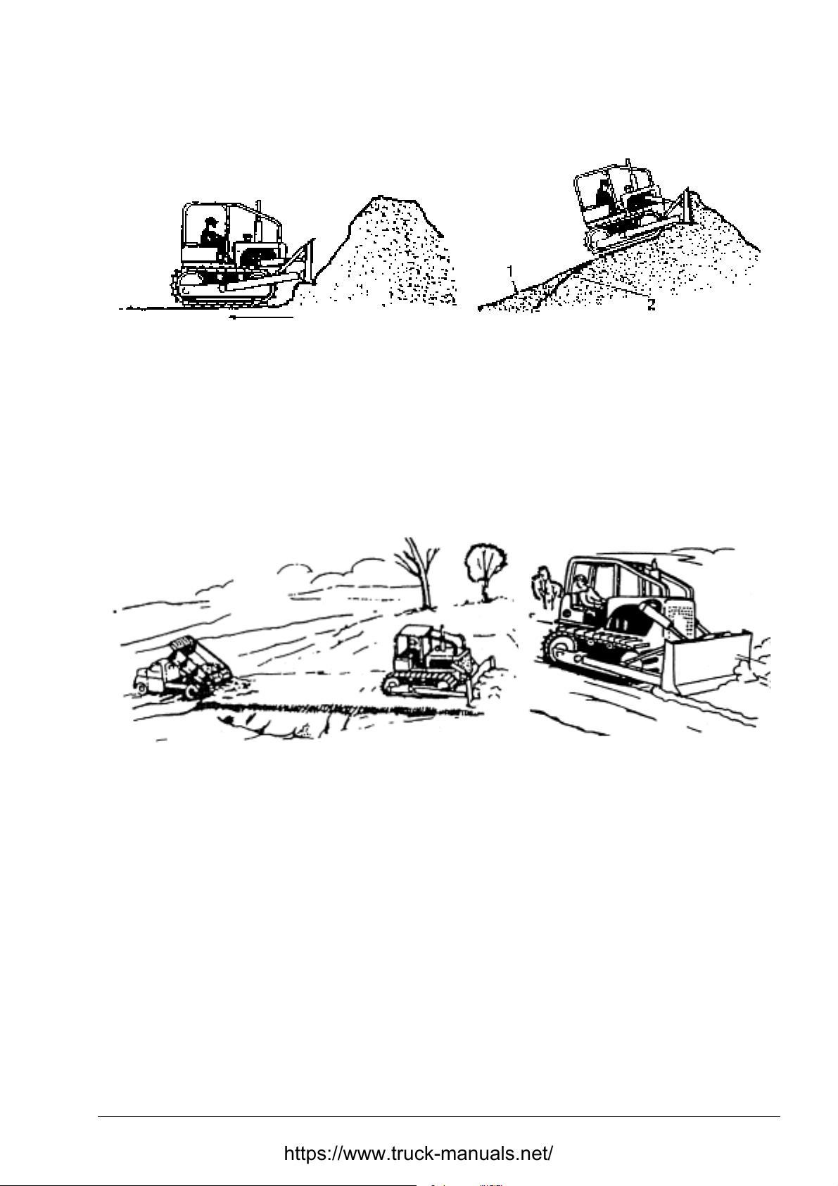
OPERATING SECTION 4
Page 39
OPERATING TECHNIQUES
Fig. 4.43. Breaking Down a Pile
Method 1 Method 2
1. Ramp 2. Original Slope
When trucks or wagons are used for hauling, bulldozers are ideal spreading tools at the fill
(Fig. 4.43). Blade should be kept in the straight position so that the material is drifted direct ly under
the cutting edge (Fig. 4.44). When f inishing in non-solid materials, such as earth, drag the blade
backward for a smooth job as shown in Fig. 4.45. Rock, of course, may damag e the blade base,
therefore, such practice is not r ecom mended where abrasive material is common.
Fig. 4.44. Spreading Material Forward Fig. 4.45. Back Drag ging
4.19.4. RIPPING
4.19.4.1. Prior to Operation
Before operating the r ipper proceed as follows:
1. Check all mounting hardware for t orque.
2. Check the hydraulic connections for leaks.
3. Check the condition of the ripper, bits, mounting hardware for completeness and torque.
DRESSTA TD-25H
Page 78

SECTION 4 OPERATING
Page 40
OPERATING TECHNIQUES
4.19.4.2. Ripping Techniques
When start ing ripping lower the ripper teeth slowly to the req uired depth. Ripping of rock material
must be performed in direction of easier ripping which may be established by carrying out test
ripping in various directions and under various angles of inclination of the shanks. During test
ripping lower the shank to the half of working depth. Machine efficiency can be improved when
several centimeters of loose material is left on solid rock. Ripping should be perf ormed at a depth
the best results are obtained without overloading the engine. Keep loose ground level and
horizontal as mach as possible. Never make turns with the machine with ripper teet h at f ull depth
in rocky ground. Use common sense when working in har d ground not to damage the ripper and
the machine. Do not accelerate the machine and simultaneously lower the ripper teeth into the
ground – this will damage the ripper.
Pay attention not to allow the rear of the m achine to lift off the ground dur ing ripping operations, as
this decreases traction and accelerates wear of the track system. Use new and sharp bits for hard
ground.
4.19.4.3. Cold Weather Operation
Start the engine as described in “ST ARTING THE ENGINE” and then proceed as follows:
• Move slightly and slowly ripper control lever to warm the oil in the hydraulic cylinders.
• Raise the ripper at the max. height and t hen lower it slowly until it rest s on the ground.
• Increase gradually pressure in the ripper cylinders by keeping the control lever in LOWER
position until the rear of the m achine is off the ground.
• Prior to norm al ripping operations operate the ripper at low depth for a couple of minutes to
warm the shank bits.
• Protect the shank and bits when parking the machine.
4.20. ECONOMICAL OPERATION OF THE MACHINE
Fuel consumption during operation of a dozer depends on many f actor s as: eng ine charact eristics,
load, terrain, operator’s skill and experience, the manner of operation.
A relatively conclusive indicator of fuel consumption is the quantity on moved material per unit of
consumed fuel. To reach the most f avorable value of this ratio observe the following principles of
dozer operation:
• Avoid long distance transporting of m at e r ial.
• Loading and pushing of material must be performed at the gear which ensures maximum
drawbar pull (1
st
or 2nd gear) with high blade fill rat io without losing the material in blade.
• Reverse travel at top gear but keep eng ine speed above medium , not maximum.
• Avoid stopping the machine due to stall of t he engine.
• Avoid track slippage.
• For digging hard material pitch the blade forward, f or transpor tation of mater ial pitch the blade
backward.
TD-25H DRESSTA
Page 79

SECTION 5
MAINTENANCE
Page 80

Page 81

MAINTENANCE SECTION 5
SECTION CONTENTS
5.1. Service Precautions ........................................................................................................... 3
5.2. Scheduled Maintenance Guide .......................................................................................... 4
5.2.1. Ground Level Inspection .......................................................................................... 6
5.3. Maintenance and Service Chart ......................................................................................... 7
5.3.1. Refill Specifications and Capacities Chart ............................................................... 9
5.4. Lubrication ....................................................................................................................... 10
5.4.1. When Shipped ........................................................................................................10
5.4.2. When Serviced ...................................................................................................... 11
5.4.3. Selection ................................................................................................................11
5.4.4. Viscosities ...............................................................................................................11
5.4.5. Recommended Lubricant Chart ............................................................................. 12
5.5. Seasonal Preparation........................................................................................................ 13
5.5.1. Fuel System .......................................................................................................... 13
5.5.2. Cooling System ..................................................................................................... 13
5.5.3. Electric System ...................................................................................................... 13
5.6. Air Cleaning System ....................................................................................................... . 14
5.6.1. Air Pre-cleaner .......................................................................................................14
5.6.2. Air Cleaner .............................................................................................................14
5.6.2.1. Primary Filter Element .............................................................................. 15
5.6.2.2. Safety Filter Element ................................................................................ 16
5.6.3. Checking Air Intake System for Leaks ................................................................... 17
5.7. Belts ................................................................................................................................. 17
5.7.1. Visual Inspection ................................................................................................... 17
5.7.2. Checking Tension and Adjustment ....................................................................... 18
5.7.2.1. Checking Tension and Adjustment of A/C Compressor Belt ....................... 19
5.7.2.2. Checking Tension and Adjustment of Alternator Belt ................................. 19
5.7.3. Belt Replacement ....................................................................................................19
5.8. Cooling System ................................................................................................................ 19
5.8.1. W ater ..................................................................................................................... 20
5.8.2. Antifreeze .............................................................................................................. 20
5.8.3. Inhibitors / Conditioners ..........................................................................................20
5.8.4. Radiator Cap ...........................................................................................................21
5.8.4.1. Radiator Cap Cover ..................................................................................... 21
5.8.4.2. Cleaning the Radiator Core...........................................................................22
5.8.5. Checking Coolant Level ......................................................................................... 22
5.8.6. Changing Coolant....................................................................................................23
5.8.6.1. Draining the System..................................................................................... 23
5.8.6.2. Filling the Drained System.............................................................................23
5.8.7. Changing the Coolant Filter.................................................................................... 24
5.9. Fan ................................................................................................................................... 24
5.10. Electric System ................................................................................................................ 25
5.10.1. Electric Wires and Connections............................................................................ 25
5.10.2. Automatic Reset Circuit Breaker ......................................................................... 25
5.10.3. Batteries ..............................................................................................................25
5.11.Engine ............................................................................................................................. 28
5.11.1. Checking the Crankcase Oil ................................................................................ 28
5.11.2. Changing the Crankcase Oil and Oil Filter .......................................................... 28
5.11.3. Ether Injector........................................................................................................30
DRESSTA TD-15H
Page 82

SECTION 5 MAINTENANCE
Page 2
5.12. Fuel System ..................................................................................................................... 32
5.12.1. Filling the Fuel Tank ............................................................................................ 32
5.12.2. Fuel Tank Filler Strainer ...................................................................................... 32
5.12.3. Fuel Tank Shutoff Valve ...................................................................................... 33
5.12.4. Fuel Filters .......................................................................................................... 33
5.12.4.1. Fuel Filter Water Separator Drain Valve ..............................................33
5.12.4.2. Replacing the Fuel Filters ................................................................... 34
5.12.5. Draining Fuel Tank ...............................................................................................34
5.13.Hydraulic System ............................................................................................................. 35
5.13.1. Checking Oil Level .............................................................................................. 35
5.13.2. Changing Hydraulic Oil ....................................................................................... 35
5.13.3. Replacement the Return Filters and Pilot Filter.................................................... 37
5.13.4. Servicing the Suction Strainer and Filler Strainer................................................. 38
5.13.5. Servicing the Reservoir Breather ........................................................................ 39
5.13.6. Venting the Hydraulic System ............................................................................. 40
5.14.Lubricating Fittings ........................................................................................................... 40
5.15.Mounted Equipment ........................................................................................................ . 45
5.15.1. Complete Blade Removal and Installation ............................................................45
5.15.2. Diagonal Struts Adjustment ................................................................................ 46
5.15.3. Upper Strut and Tilt Cylinder Adjustment ............................................................ 47
5.15.4. Pitch Cylinder Loose Adjustment ....................................... .............................. ... 49
.............. ................................................................ 49
5.15.5. Checking the Blade Condition
5.15.5.1. Trunnion and Cap Mounting Bolts ....................................................... 49
5.15.5.2. Blade Cutting Edge and End Bits Mounting Bolts
5.15.5.3. Allowable Wear of Cutting Edge and End Bits and Ripper Points
.............. .................. 50
...... 50
5.15.6. Servicing the Ripper ............................................................................................ 51
5.16.Safety Belt ....................................................................................................................... 51
5.17.Final Drives ...................................................................................................................... 51
5.17.1. Checking the Oi l Level ........................................................................................ 51
5.17.2. Changing the Oil ..................................................................................................52
5.18.Transmission System ....................................................................................................... 52
5.18.1. Checking the Oil Level in RMF ........................................................................... 52
5.18.2. Changing Transmission System Oil .................................................................... 53
5.18.3. Servicing the Transmission Pressure Filters ....................................................... 54
5.18.4. Servicing the Suction Strainer.............................................................................. 55
5.18.5. Servicing Transmission Scavenger Strainer ........................................................ 57
5.18.6. Servicing the Breather .........................................................................................57
5.19. Undercarriage .................................................................................................................. 58
5.19.1. Track Shoe Bolts................................................................................................. 58
5.19.2. Effect of Track Adjustment on Undercarriage Wear ............................................ 58
5.19.3. Checking the Te nsion ......................................................................................... 59
5.19.4. Adjusting Te nsion ............................................................................................... 59
5.19.5. Track Frame Guide ............................................................................................. 61
5.19.6. Pivot Shaft Housing ............................................................................................ 62
5.19.7. Front Wheel Guides ............................................................................................ 63
5.20.Adjusting Hand and Foot Controls .................................................................................... 64
5.21.Cab and ROPS ................................................................................................................ 65
5.21.1. ROPS Cab/Canopy and Mounted Equipment Mounting Hardware ..................... 65
5.21.2. Air Conditioning Cleaning .................................................................................... 65
5.21.3. Windshield Washer Reservoir.............................................................................. 66
TD-25H DRESSTA
Page 83
MAINTENANCE SECTION 5
Page 3
5.1. SERVICE PRECAUTIONS
CAUTION! Only authorized personnel, thoroughly trained with the design and
operation of all assemblies and mechanisms may be allowed to service this
machine.
WORK SAFELY – FOLLOW THESE RULES
CAUTION! If a machine is operated in any circumstances involving dust as in
coalmines, wash the engine compartment and check the fuel lines and electric
wires at least once a week.
A CAREFUL OPERATOR IS THE BEST INSURANCE AGAINST AN ACCIDENT.
GENERAL SERVICE PRECAUTIONS
The procedures in this section contain many notes and precautions, which should be followed
along with standard safety procedures to minimize a possibility of personal injury or improper
service. Improper service could compromise a machine's safety or cause it to function improperly,
which could result in personal injury or death. Review the precautions listed in Section 2, “SAFETY
PRECAUTIONS".
Do not attempt to do repairs you do not understand. Use your "Service Manual" or consult your
Authorized Distributor for information.
Do not jump on or off a machine.
When working under a machine or servicing in the area of the engine fan or belts, turn the electric
system master switch OFF, apply and lock the parking brake and tag controls to warn against
starting the machine.
Whenever servicing, take care to prevent accidental cranking of the engine. Turn the electric
master switch OFF and remove the key. It is not possible to anticipate all conceivable ways or
conditions under which a machine may be serviced or to provide precautions for all the possible
hazards that may result. Safety is always the most important rule.
Constantly be aware of dangers involved in working on a machine and take proper precautions.
Standard and accepted safety precautions and equipment should be used.
This machine is assembled using high strength fasteners. Do not substitute. Replacement
fasteners must be of the same size and strength as the originals (refer to Section 6). Tighten
fasteners to the proper torque value specified in Section 6, unless otherwise specified.
Refer to Spare Parts Catalogue for all replacement parts.
Use safety goggles, hard hats, safety shoes, heavy duty gloves and other protection during cutting,
grinding, chiseling, prying or any other process which could cause material removal or projectiles.
Many machined parts are hardened and can chip.
Use the proper size and type of tool for the job being done. Select a wrench that fits and be sure it
is on straight. Keep your tools clean and in good condition.
Some procedures require the use of tools specially designed for that specific purpose.
Before substituting another tool or procedure, you must be completely satisfied that neither
personal safety nor the performance of the machine will be endangered.
DRESSTA TD-25H
Page 84

SECTION 5 MAINTENANCE
Page 4
5.2. SCHEDULED MAINTENANCE GUIDE
Scheduled maintenance is the normal maintenance necessary to provide proper and efficient
equipment operation and t o prolong of your machine’s service life.
Every 10 Hours of Operation (Every Day)
1. Clean windows, lights and instrument panel.
2. Drain water from fuel filters prior to starting the work. Refer to 5.12.4.1.
3. Check engine oil level. Refer to 5.11.1.
4. Check hydraulic system oil level. Refer to 5.13.1.
5. Visually check the condition of drive belts. Refer to 5.7.1.
6. Visually check the condition of fan. Refer to 5.9.
7. Check radiator coolant level. Refer to 5.8.5
8. Check and clean precleaner screen, if necessary. Refer to 5.6. 1.
9. Check level in window washer reservoir. Refer to 5.21.3.
10. Carry out ground level inspection. Refer to 5.2.1.
11. Check instruments and warning lights for operation. Refer to 4.3.
12. Refill fuel tank at the end of each day’s operation. Refer to 5.12.1.
13.* Check torque:
– track shoe bolts. Refer to 5.19.1.
– blade cutting edge and end bit bolts. Refer to 5.15.5.2.
– trunnion cap bolts and trunnion mounting bolts. Refer to 5.15.5.1.
* – after initial 10 hours of operation only.
Every 50 Hours of Operation
1. Check oil level in rear mainframe. Refer to 5.18.1.
2. Clean radiator cores. Refer to 5. 8.4.2.
3. Check and adjust tracks tension, if necessary. Refer to 5.19
4. Check air intake system for leaks (hoses and clamps). Refer to 5.6.3.
5. Lubricate ripper bearings. Refer to 5.14.
6. Lubricate lift cylinder piston rod bearings. Refer to 5.14.
7*. Replace hydraulic system return filters. Refer to 5.13.3.
8*. Replace transmission system pressure filters. Refer to 5.18.3.
9*. Replace equipment pilot filter. Refer to 5.13.3.
* – after initial 50 hours of operation only.
Every 100 Hours of Operation
1. Lubricate blade lift cylinders yoke bearings. Refer to 5.14.
Every 250 Hours of Operation or every 6 months
1. Replace fuel filters (2 filters). Refer to 5.12.4.2.
2. Change engine oil filters (2 filters). Refer to 5.11.2.
3. Check coolant for DCA concentration and replace coolant filter. Refer to 5.8.7.
4. Change engine crankcase oil. Refer to 5.11.2.
5. Check fan, alternator and water pump belt and air compressor or air conditioner (if equipped)
belt tension. Refer to 5.7.2.
6. Check the condition of the fan (if equipped reverse the reversible fan blades) Refer to 5.9.
7. Check final drive oil level. Refer to 5.17.1.
8. Lubricate upper struts and joints. Refer to 5.14.
9. Lubricate diagonal struts and joints. Refer to 5.14.
TD-25H DRESSTA
Page 85

MAINTENANCE SECTION 5
SCHEDULED MAINTENANCE GUIDE
Every 500 Hours of Operation or every year
1. Check oil level in pivot shaft housing. Refer to 5.19.6
Every 1000 Hours of Operation
1. Change final drive oil. Refer to 5.17.2.
2. Change oil in rear mainframe. Refer to 5.18.2.
3. Replace transmission suction strainer. Refer to 5.18.4.
4. Replace transmission system pressure filter. Refer to 5.18.3.
5. Clean transmission system scavenger suction strainer. Refer to 5.18.5.
6. Replace hydraulic system return filter. Refer to 5.13.3.
7. Replace rear mainframe breather. Refer to 5.18.6.
8. Clean hydraulic reservoir breather. Refer to 5.13.5.
9. Lubricate gimbal crosstube. Refer to 5.14.
10. Check sprocket bolt torques. Refer to 5.19.
Page 5
Periodic (at least once a year or as required)
1. Lubricate hand and foot linkage, check for operation and adjust if necessary.
Refer to 5.20. and 5.14.
2. Check condition and state-of-charge of batteries. Refer to 5.10.3.
3. Clean air cleaner elements or replace if necessary. Refer to 5.6.2.1. and 5.6.2.2.
4. Clean fuel tank filler strainer. Refer to 5.12.2.
5. Drain water and sediment from fuel tank sediment bowl. Refer to 5.12.5.
6. Clean hydraulic system filler strainer. Refer to 5.13.4.
7. Lubricate the equipment pilot valve plunger – to – plate surfaces. Refer to 5.14.
8. Clean the air conditioner outside filter. Refer to 5.21.2.
9. Check engine RPM with depressed decelerator. Refer to 5.20.
10. Check operation of brake and decelerator pedal. Refer to 5.20.
11. Check undercarriage components for wear. Refer to 5.19.
12. Check track frames guide clearance and adjust if necessary, lubricate track frame guides.
Refer to 5.19.5 .
13. Check clearance in blade sockets of diagonal struts, upper struts and pitch cylinder and adjust
if necessary. Refer to 5.15.2., 5.15.3.
14. Check condition of electrical wires and connections. Refer to 5.10.1.
15. Check condition of safety belt. Refer to 5.16.
16. Check torque:
– cab and ROPS mounting bolts. Refer to 5.21.1.
– track shoe mounting bolts. Refer to 5.19.1.
– blade cutting edge and end bit bolts. Refer to 5.15.5.2.
– trunnion cap bolts and trunnion mounting bolts. Refer to 5.15.5.1.
17. Check the cutting edges and end bits for wear. Refer to 5.15.5.3.
18. Check the ripper points for wear. Refer to 5.15.6.
19. Wash the machine inside by water stream.
20. Check front wheel guide clearance. Refer to 5.19.7.
DRESSTA TD-25H
Page 86

SECTION 5 MAINTENANCE
Page 6
SCHEDULED MAINTENANCE GUIDE
Every 1500 Hours of Operation or every year
(Per Engine Operator’s Manual)
1. Clean or replace crankcase breather tube if necessary.
2. Adjust engine valves and injectors.
3. Steam clean the engine.
4. Check and replace engine hoses if necessary.
5. Check engine mounting bolts and nuts and torque if necessary.
6. Check turbocharger mounting nuts.
Every 2000 hours of operation
1. Change radiator coolant. Refer to 5.8.6.
2. Replace system pilot filter. Refer to 5.13.3.
3. Change hydraulic system oil. Refer to 5.13.2.
4. Clean hydraulic system suction strainer. Refer to 5.13.4.
Every 6000 Hours of Operation or every 3 years
(Per Engine Operator’s Manual)
1*. Calibrate injectors and fuel pump.
2. Check and clean crankcase breather tube.
3. Drain and flush cooling system. Change coolant and replace coolant filter.
4. Inspect condition of fan and fan hub.
5. Inspect condition of coolant pump idler pulley
6. Inspect condition of coolant pump.
7. Inspect condition and end play of turbocharger.
8. Inspect condition of vibration dumper.
* – after initial 1500 hours of operation and then each 6000 hours only.
5.2.1. GROUND LEVEL INSPECTION
1. Tractor operational equipment for damage and state of proper fastening.
2. Radiator: for damage, evidence of leakage and condition of grill.
3. Hydraulic components for damage or leakage.
4. Track system: rollers, front idlers, sprockets, track shoes for: cracks, excessive wear, loose
components and leaks.
5. Transmission system and final drives: for possible leakage.
6. Engine compartment for fuel, oil and coolant leaks.
7. Guards: for damage or missing.
8. ROPS: general condition (no ROPS defects are permissible that may adversely affect its
protection in case of machine rollover).
CAUTION! To ensure personal protection perform all maintenance services in
accordance with Scheduled Maintenance Guide and Instructions
To extend the service life of your equipment follow the scheduled maintenance listed in Scheduled
Maintenance Guide.
TD-25H DRESSTA
Page 87
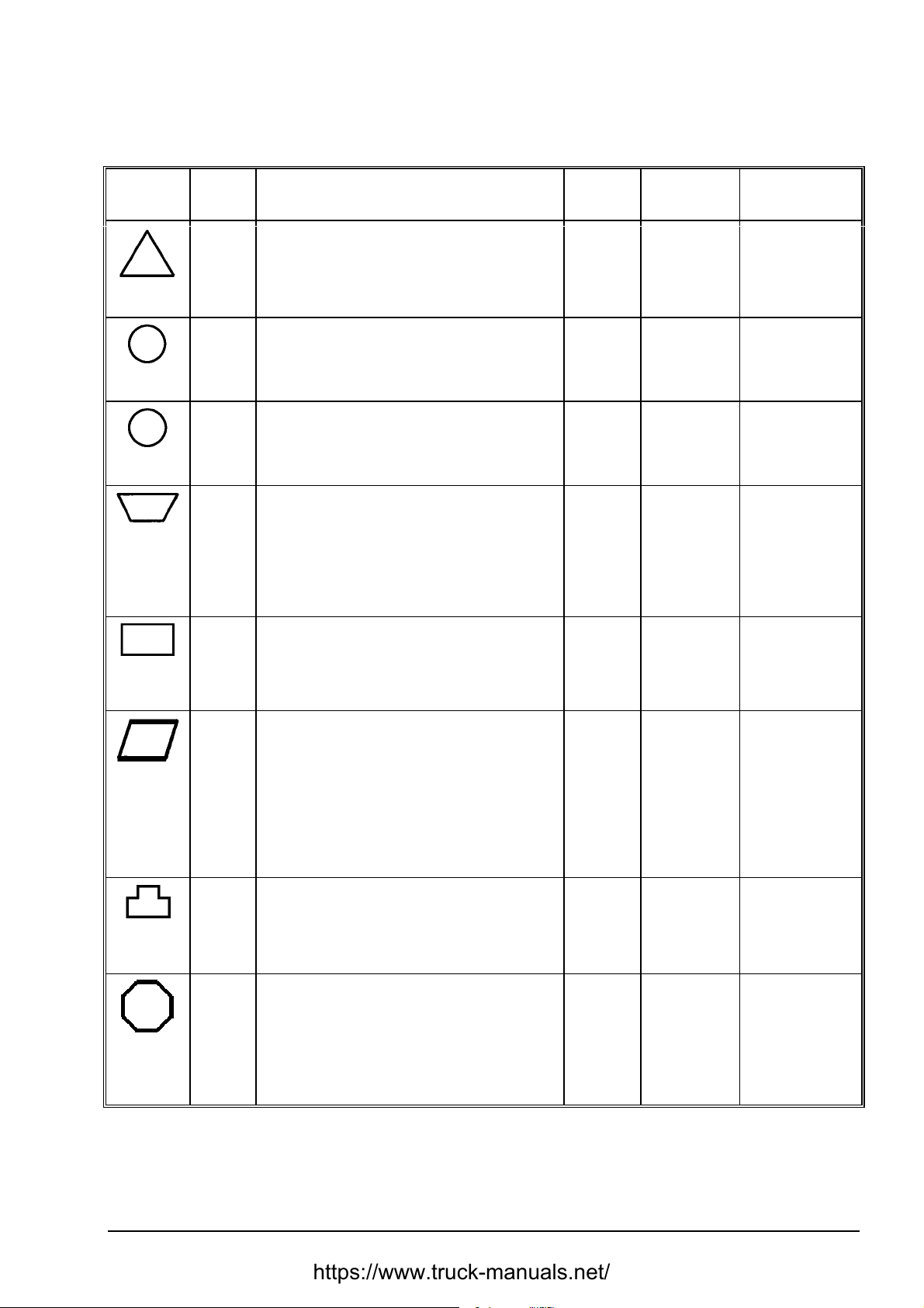
MAINTENANCE SECTION 5
5.3. MAINTENANCE AND SERVICE CHART
(Always use clean containers and lubricators)
Page 7
SERVICE
INTERVAL
Every 10
Hours
Every 50
Hours
Every 100
Hours
Every 250
Hours
or 3
Months
REF. No POINT OF SERVICE
Fuel Filter Water Separator
8
12
25
32
20
23
34
31 Blade Lift Cylinders Yok e Bearin gs 4 MPG Lube
11
13
18
33
35
17 Pivot Shaft Housing Oil Level 2 HDTF Check
Engine Crankcase Oil Level
Hydraulic Reservoir Oil Level
Radiator Coolant Level
Ground Level Inspection
Transmission System Oil Level
Ripper Bearings and Pins Cylinder
Lift Cylinder Piston Rod Bearings
Fuel Filter
8
Engine Crankcase Oil Filter
9
Engine Coolant Filter, DCA- Concentration
Engine Crankcase Oil Level
Final Drive Oil Level
Upper Struts
Diagonal Strut Socket
SERVICE
POINTS
2
1
1
1
1
12
2
2
2
1
1
2
4
2
LUBRICANT SERVICE
EO1
HDTF/EO2
HDTF
MPG
MPG
EO1
MPL
MPG
MPG
Drain
Check
Check
Check
Check
Check
Lube
Lube
Change
Change
Check, Change
Change
Check
Lube
Lube
Every 500
Hours or 6
Month
Change
Change
Change
Change
Clean
Change
Change
Clean
Lube
Change
Change
Change
Clean
Lube
Inspect
Clean/Change
Clean
Drain
Clean
Lube
Every
1000
Hours or
12 Month
Every
2000
Hours
Periodic or
at Least
Once a
Year
1
2
3
4
14
15
19
26
30
10
16
24
27
5
6
7
21
22
28
29
Final Drive Oil
Transmission System Oil
Transmission Suction Strainer
Transmission System Pressure Filter
Transmission System Scavenger Strainer
Hydraulic System Return Filter
Rear Frame Breather
Hydraulic Reservoir Breather
Gimbal Crosstube
Engine Coolant
System Pilot Filter
Hydraulic System Oil
Hydraulic Oil Suction Strainer
Hand and Foot Control Linkage
Batteries
Air Cleaner Element
Fuel Tank Strainer
Fuel Tank Sediment Bowl
Hydraulic Filler Strainer
Pilot Valve Plunger – to – Plate Surf ac es
2
1
1
2
1
2
1
1
2
1
1
1
1
all
1+1
1
1
1
2
MPL
HDTF
MPG
HDTF/EO2
MPG
MPG
Lubricant Key:
EO1 - Engine Oil HDTF - Heavy Duty Hydraulic Transmission Fluid
EO2 - Multi-purpose Engine Oil MPL - Multi-purpose Transmission Oil
MPG - Multi-purpose Grease
DRESSTA TD-25H
Page 88
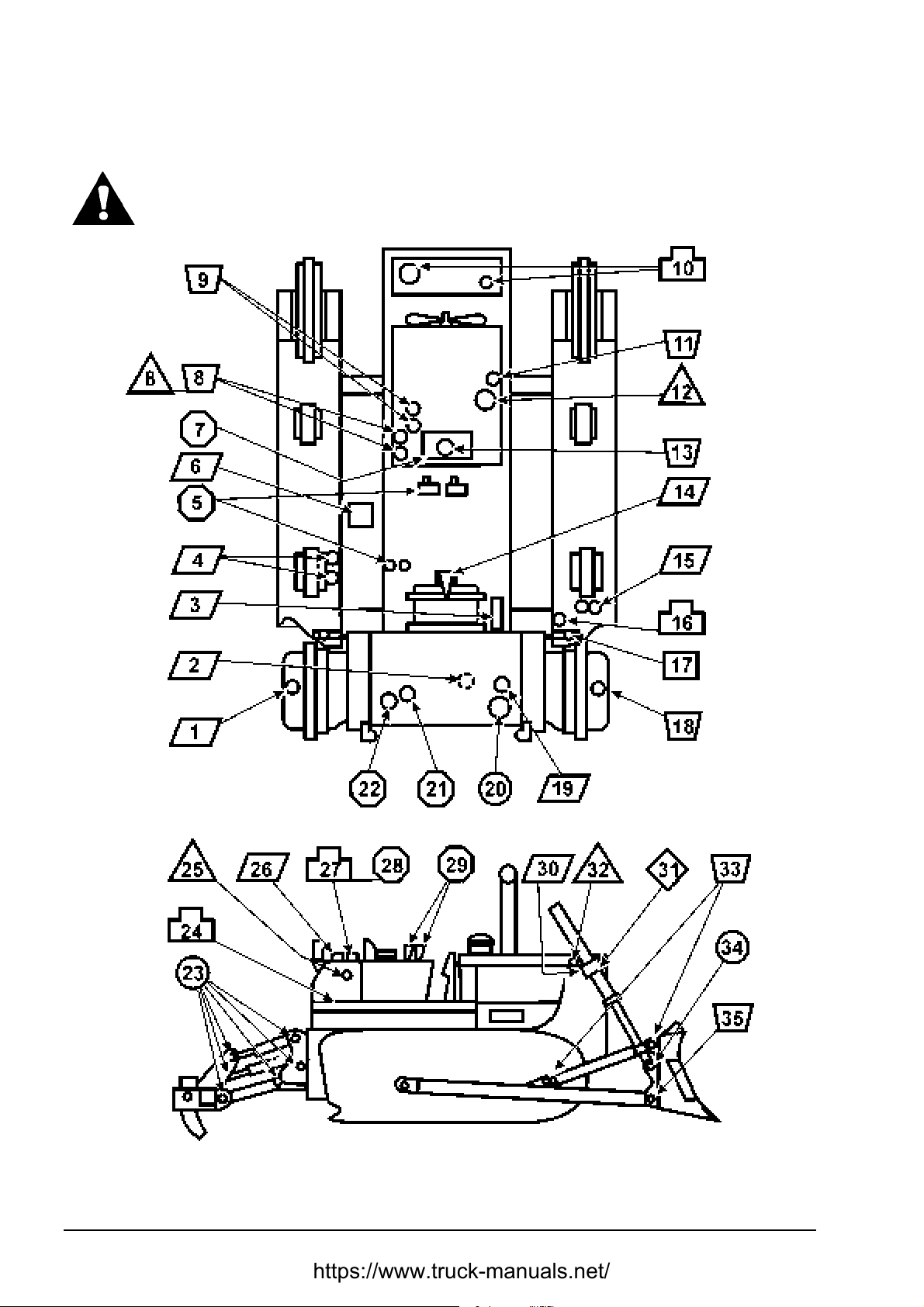
SECTION 5 MAINTENANCE
Page 8
MAINTENANCE AND SERVICE CHART
CAUTION! Intervals of time between services are based on average operating conditions.
Under unusually severe conditions of operation, reduce the intervals of time between
services. Service a machine according to Scheduled Maintenance Guide Instructions.
Fig. 5.1. Service Guide
TD-25H DRESSTA
Page 89
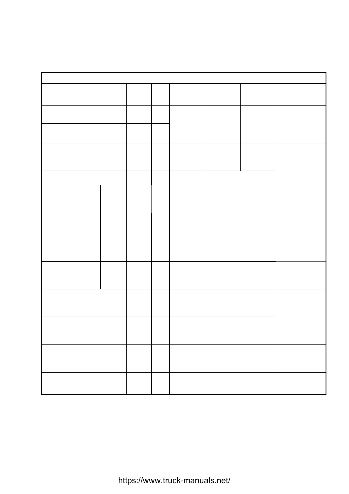
MAINTENANCE SECTION 5
MAINTENANCE AND SERVICE CHART
5.3.1. REFILL SPECIFICATION AND CAPACITIES CHART
MODEL TD-25H
Lubrication
Point
Final Drive - Each
Pivot Shaft Housing - Each
Refill
capacity
46 [l]
4.5 [l]
Type
MPL
MPL
Air
Temperature
+49 – -7 [°°°°C]
SAE 85W-140
Temperature
+21 – -23 [°°°°C]
SAE 85W-140
SAE 80W - 90
Air
or
Temperature
-12 – -34 [°°°°C]
SAE 80W-90
Page 9
Temperature
-12 – -54 [°°°°C]
MPL - ARCTIC
ARCTIC GRADE 75
per HMS-B22-0003
Engine Crankcase with Filter Change
Transmission System (RMF)
Track
Roller
Life Time
Lubrication If Rebuilt
(each)
Top Idler
(each)
Front
Idler
Life Time
Lubrication If Rebuilt
Life Time
Lubrication If Rebuilt
(each)
Lubricated
track chain
Life Time
Lubrication If Rebuilt
link (each)
D-2 Equipment Hydraulic System
42 [l]
220[l]
0.9 [l]
1.1 [l]
0.8 [l]
0.03 [l]
approx
(each)
130 [l]
EO1 SAE 15W-40
SAE 10W-30
SAE 15W-40
HDTF SAE 10W
HDTF
or
EO2*
MPL SAE 85W
..
.
HDTF
or
EO2*
or
SAE 30
SAE 10W
SAE 5W-20
or
SAE 5W-30
EO - ARCTIC
MULTI – PURPOSE
per HMS-B21-0001
MPL - ARCTIC
ARCTIC GRADE 75
per HMS-B22-0003
EO ARCTIC OIL PER
HMS-B21-0001
D-2 Equipment Hydraulic System
w/Ripper
165 [l]
HDTF
or
EO2*
SAE 10W
EO ARCTIC OIL PER
HMS-B21-0001
ANTI-FREEZE SOLUT ION
Cooling System
92 [l]
0° – -37 [°C]
50 [%] Anti-freeze
62 [%] Anti-freeze
38 [%] Water
50 [%] Water
Fuel Tank
825 [l]
above -12 [°C] Diesel Fuel # 2D
below - 12 [°C] Diesel Fuel # 1D
Diesel Fuel
VV-F-800DF-A
* - for servicing only
DRESSTA TD-25H
Page 90

SECTION 5 MAINTENANCE
Page 10
MAINTENANCE AND SERVICE CHART
DESCRIPTION:
HDTF:
Heavy Duty Transmission Fluid per HMS B21-0006 or equivalent and passing formula C-4 and
TO-4. Should not contain viscosity-improving agent.
EO1:
CF-4 or SG-4 Engine Oil meeting API requirements, or per MIL–L–2104D Standard and per
HMS B21-0002 with sulfated ash of 1.85% maximum.
EO2:
Multi – purpose engine oil per HMS B21-0003 or CD engine oil meeting API requirements,
or MIL-L-2104C Standard and passing TO-2 and C-3 test with 0.10% minimum zinc.
EO:
Arctic selection: multi-purpose oil per HMS B21-0001or MIL-L-46167
MPL:
Multi – purpose gear lubricant per HMS B22-0003 or API GL-5 or MIL-L-2105C
Arctic selection: grade 75 per HMS B22-0003
MPG:
Multi – purpose grease 251 HEPM per HMS B27-0002 or NLGI grade #2 - lithium grease with 3%
minimum molybdenum disulfide (MoS
Arctic selection: per HMS B27-0003 or MIL-L-10924D
ANTI-FREEZE:
Single phase, ethylene glycol base per HMS B01-0001.
DIESEL FUEL:
Per HMS B32-0001 or ASTM 2975
Arctic selection: per VV-F-800DF-A
) contents.
2
IMPORTANT: Intervals of time between services are based on average operating conditions.
Under unusually severe conditions of operation, reduce the intervals of time between services.
Service a machine according to Scheduled Maintenance Guide Instructions at least once a year.
5.4. LUBRICATION
5.4.1. WHEN SHIPPED
This machine has been lubricated at the factory for operation in an air temperature range
of +21 [°C] to – 23 [°C]. If this tractor is to be operated above or below this range, change to the
correct lubricants.
Unless an exception is shown below, all lubricants can be used (within above temperature range)
until regular scheduled (normal) change intervals occur. Refer to "MAINTENANCE AND SERVICE
CHART" for the scheduled (normal) change intervals and to "REFILL SPECIFICATIONS AND
CAPACITIES CHART" for the proper oil grades for ambient temperat ures.
Front idlers, track idlers and track rollers are permanently lubricated with a SAE 30, API CD or MILL-2104C engine oil. Lubricated track chain links are permanently lubricated with SAE 85W multipurpose lubricant. Level check of these compartments is not required.
TD-25H DRESSTA
Page 91
MAINTENANCE SECTION 5
Page 11
LUBRICATION
5.4.2. WHEN SERVICED
WARNING! When you service a machine, always follow the Operator's or Service
Manual. Never grease, oil or perform any maintenance alone with the engine
running. Always have another experienced person helping in the operator's
compartment when maintenance must be done with the engine running. Block
up all attachments securely. Do not leave the operator's seat with the engine
running. Failure to follow these instructions could result in serious injury or
death.
The life and performance of a tractor and its equipment depends on the service that it is given.
Proper lubrication is an important part of maintenance service. Thorough lubrication service
performed at specified intervals will aid in prolonging the life of the tractor and its equipment and in
reducing operating expense. The type of work being done, load, ground and weather conditions
are all factors to consider in frequency of lubrication.
The scheduled intervals between lubrication periods shown on the "SERVICE CHART" are
approximate, based on average operating conditions. It may be necessary to lubricate after shorter
working periods under severe operating conditions such as extreme dust, low engine
temperatures, intermittent operation, excessively heavy loads with high oil temperatures, or when
diesel fuel with a high sulfur content is used. However, the time intervals between lubrication
periods must never exceed those indicated in this manual.
5.4.3. SELECTION
The selection of the proper type (specification) and the grade (weight or viscosity) of lubricant is
important. Many tests have been made to determine the correct lubricants for this tractor and its
equipment. Refer to “REFILL SPECIFICATION AND CAPACITI ES CHART" for the recommended
time intervals and grades of lubricants.
5.4.4. VISCOSITIES
During cold weather, base the selection of crankcase lubricating oil viscosity on the lowest
anticipated temperature for the day to make starting easier. For hot weather operation, base the
selection on the highest anticipated temperature. Refer to the "REFILL SPECIFICATIONS AND
CAPACITIES CHART".
IMPORTANT: After the oil has been replaced, start the engine according to the instructions
specified in Section 4, "ENGINE START AFTER OIL CHANGE OR PROLONGED STANDSTILL".
DRESSTA TD-25H
Page 92

SECTION 5 MAINTENANCE
Page 12
LUBRICATION
5.4.5. RECOMMENDED LUBRICANT CHART
RECOMMENDED EQIVALENT LUBRICANT TYPE
LUBRICANT POLISH SHELL TEXACO
Engine oil per HMS B21-0002
or API CF-4 or SG-4 per
MIL-L-2104D with sulfated ash
of 1.85% maximum
SAE 15W/40 AQUILA DIESEL
TURBO CE/CF-4/SG
SAE 15W/40
SAE 10W/30 MYRINA TX 10W/30 URSA TDX 10W/30
SAE 5W/40 HELIUS S A E 5W/40
Engine oil per HMS B21-0003
or CD MIL-L-2104C
SAE 10W SUPEROL CD
SAE 10W
SAE 30 SUPEROL CD
SAE 30
Transmission Fluid HDTF per
HMS B21-0006 passing
formula C-4 and TO-4 tests
SAE 10W GERAX TKD 10W DONAX TC 10W TEXTRAN HD 10W HDTF
SAE 30 GERAX TKD 30 DONAX TC 30 TEXTRAN HD 30
Gear Lube per
HMS B22-0003 or API GL-5 or
MIL-L-2105C
SAE 85W/140 HIPOL 85W/140 SPIRAX HD
SAE 80W/90 HIPOL 80W/90 SPIRAX HD 80W/90 GEARTEX EP-C
Multi-purpose grease per HMS
B27-0002 or NLGI lithium
grease grade #2 with 3%
MoS
2
Anti-freeze, ethylene glycol
base per HMS B1-0001
Arctic oil, synthetic 75W per
HMS B22-0003 – – – – – – – – – – – –
Arctic engine Oil, synthetic per
HMS B21-0001
or MIL-L-46167 – – – – – –
Arctic grease per
HMS B27-0003 or
MIL-L-10924D
LITOMOS EP-23
ERGOFRYZ GLYCOSHELL
– – – – – –
RIMULA TX 15W/40 URSA SUPER LA
15W/40 EO1
ROTELLA TX 10W URSA SUPER LA
10W EO2
ROT E LLA T X 30 URSA SUPER LA
30
GEARTEX EP-C
85W/140
RETINAX EPX2 MOLYTEX EP-2
DILUTED
CHEVRON SUB–ZERO
Fluid OW-30 manufactured by CHEVRON
or FRIGID-GO 2809A manufactured by
EMERY Ind.
SRI grease manufactured by CONOCO
Grease 2816 manufactured by EMERY Ind.
85W/14 MPL
80W/90
ANTIFREEZE
ETX 6042
SYN-STAR 75W
CODE 2080
MPG
MPL
ARCTIC
EO
ARCTIC
MPG
ARCTIC
Diesel Fuel
Per HMS-B32-0001
Diesel fuel per Polish Standard PN-C-96051:1992
DL above 0[°C]
DP above -12[°C]
DZ above -20[°C]
IZ-40 above -30[°C]
For temperatures below -30[°C] add pour point depressant
TD-25H DRESSTA
Page 93
MAINTENANCE SECTION 5
Page 13
5.5. SEASONAL PREPARA TION
General
Mechanical efficiency is enhanced during seasonal air temperature changes, when these
instructions are followed.
Outside source of heat
Machines left outside for prolonged periods in sub-zero weather will suffer from "cold-soak."
Lubricants become viscous and incapable of lubricating moving parts. Extreme wear could result to
the engine, transmission and final drives unless proper precautions are taken.
A source of outside heat is necessary under these conditions. There are electric as well as
propane-fired engine coolant heaters available. Gas-fired forced air heaters may also be obtained
to heat the transmission and final drives.
When using such heaters follow manufacturer’s safety instructions.
WARNING! For your personal safety, use caution and follow the manufacturer's
instructions when using engine block heaters to warm the coolant or external
heaters to warm the tractor.
5.5.1. FUEL SYSTEM
Refer to "RECOMMENDED LUBRICANT CHART " for the diesel fuels selection, which will give the
most satisfactory performance in the ambient temperature.
5.5.2. COOLING SYSTEM
Prepare the cooling system as follows:
1. Check the entire engine system for leaks.
2. Inspect the condition of all hoses and replace the hose and hose clamps as necessary.
3. Check the drive belts tension and adjust tension or replace a faulty belt. Refer to "CHECKING
TENSION AND ADJUSTMENT".
4. Remove all debris from the radiator core using air or water under pressure. Direct the flow
through the core, opposite the normal direction of air flow.
WARNING! For your personal protection, water pressure should not exceed
270 [kPa] and air pressure should not exceed 210 [kPa]. Use safety goggles.
5. Clean the radiator guard and the outside of the core.
6. Protect your cooling system from damage by using approved antifreeze and coolant. Refer to
"CHANGING COOLANT".
7. Keep your cooling system clean and minimize corrosion by adding VCI at the correct intervals.
Refer to "COOLING SYSTEM".
8. Check the condition of the fan blades.
5.5.3. ELECTRIC SYSTEM
Clean the batteries and remove all corrosion from the battery terminals and cables. Repair or
replace all wires, which have worn, cracked or frayed insulation and broken or loose wires. Service
the batteries. Refer to “BATTERIES”.
DRESSTA TD-25H
Page 94
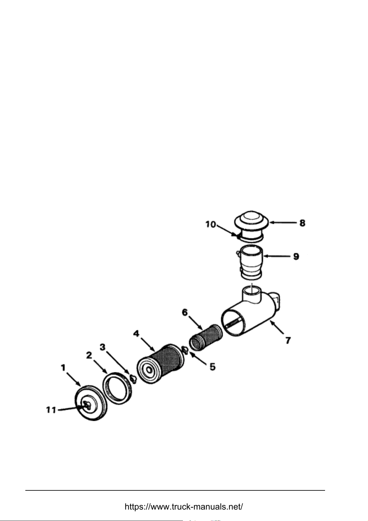
SECTION 5 MAINTENANCE
Page 14
5.6. AIR CLEANING SYSTEM
5.6.1. PRE-CLEANER (Fig. 5.2)
The air pre-cleaner consists of the pre-cleaner hood (8) with a screen. Hood (8) of the pre-cleaner
hood serves as a rain shield and the screen prevents chaff and coarse dirt from getting into the air
cleaner. Keep this screen clean from all chaff, oil or dust. Clogged holes in the screen will reduce
the power of the engine by restricting the flow of air.
Loosen clamp (10) on the pre-cleaner hood (8) securing it to the pre-cleaner (9). Twist and pull
upward to remove the hood. Use compressed air to clean the screen. If compressed air is not
available, wash the screen in a clean hot water or water containing a small amount of non-sudsing
detergent.
IMPORTANT: Never wash the pre-cleaner installed on a machine as water may penetrate to the
engine and cause a serious damage.
5.6.2. AIR CLEANER (Fig. 5.2)
Fig. 5.2. Air Cleaner with Connections (exploded view)
1. Cover
2. Cover Gasket
3. Wing Nut
4. Primary Element
TD-25H DRESSTA
5. Lock Nut
6. Safety Element
7. Cleaner Body
8. Pre-Cleaner Hood
9. Pre-Cleaner Body
10. Clamp
11. Wing Nut
Page 95

MAINTENANCE SECTION 5
Page 15
AIR CLEANING SYSTEM
This machine has a "dry-type" cleaner with replaceable elements.
The cleaner has two elements: primary and safety. The primary element can be cleaned for
a limited number of times before replacement is necessary. However, the safety element must be
replaced when plugged. Detailed service procedures for the air cleaner are covered in the following
text.
IMPORTANT: As a precaution against dirt entering the engine, all gasket and rubber hoses
between the air cleaner, turbocharger and intake manifold, and between the manifold and cylinder
head must be in good condition and the joints or connections must be tight. Never operate the
engine unless a filter element is in place and filter end gasket is installed. Never remove the
element from the air cleaner or service the air cleaner while the engine is running
5.6.2.1. PRIMARY FILTER ELEMENT (Fig. 5.2)
Service
The air cleaner primary element must be serviced whenever indicated by the air cleaner filter
warning light. Refer to "AIR CLEANER FILTER WARNING LIGHT", Section 4.
If after cleaning of the primary filter element the air cleaner filter warning light continues t o glow,
check the pre-cleaner screen for allowable restriction. If the warning light continues to glow,
replace the safety filter element. If, with the cleaned primary filter element and replaced safety f ilter
element, the warning light still continues to glow, check the air cleaner service indicator. The
primary element can be cleaned by either of two methods: washing or cleaning with compressed
air. Washing is the preferred method as it removes more dust and soot and restores the element to
an almost new condition.
The result being better performance and longer intervals between required element service. It is
recommended that a spare element be obtained for use while the serviced element is drying.
NOTE: The primary filter element must be replaced after six washings.
Cleaning an element with compressed air is not considered an entirely satisfactory method. Some
dust will remain in the element causing more frequent servicing of it. Cleaning with compressed air
should be used only as a temporary measure until sufficient time is available to clean the element
by washing.
NOTE: After cleaning, if the element is to be stored for later use, place it in a plastic bag and store
in the element-shipping container to protect against dirt and damage.
Removal (Fig. 5.2)
1. Stop the engine, lower the equipment to the ground. Open the left engine access door. Remove
all dust from the element removable end of the air cleaner body (7).
2. Unscrew the wing nut (11) and remove the cover (1) and the cover gasket (2) from the air
cleaner body (7). Unscrew the wing nut (3) and carefully remove the primary element (4) from
the body taking care not to dislodge dust from the dirty element onto the safety element (6).
3. Check the condition of the gasket on both sides of the primary element (4). If the gasket is
damaged or missing, replace the primary element.
4. Remove all dirt from the inside air cleaner body (7) with a damp cloth. A small amount of nonsudsing detergent added to the water will remove the soot.
DRESSTA TD-25H
Page 96

SECTION 5 MAINTENANCE
Page 16
AIR CLEANING SYSTEM
Washing
IMPORTANT: Never wash element in flammable liquids such as: fuel, oil, gas or solvent. DO NOT
OIL ELEMENTS. Do not tap the element against a hard surface; this will damage the element.
1. Carefully tap the side or end of the element against the palm of your hand to remove loose dust.
2. Wash the element in clean, warm water 20 [°C] to 40 [°C]. A small amount of non-sudsing
detergent added to water will remove the soot.
3. Rinse the element in clear water (if a hose is used, do not exceed 270 [kPa]). Shake the
element carefully to remove excess water.
NOTE: Do not use compressed air to speed the drying of an element; air pressure will rupture
a wet element.
4. Lay the element on its side and allow it to air-dry before reinstalling. Overnight drying is usually
sufficient. When drying an element, protect it from dirt and/or freezing.
NOTE: If no spare element is available, the wet element, after excess water has been shaken out,
may be installed in the air cleaner and the engine operated at idle for 10 minutes before operating
the tractor.
5. Inspect for damage. Refer to "INSPECTION" below.
Inspection
1. Inspect a filter element for leaks or damage by placing a bright light inside the element.
Inspection of the element on the outside will disclose any holes where concentrated light shines
through. The slightest rupture requires replacement of the filter element.
2. Inspect the contact surfaces of the air cleaner body. If faulty or damaged surfaces are noted,
correct these conditions immediately.
Installation (Fig. 5.2)
1. Insert the open end of the primary element (4) into the air cleaner body (7) and secure it with
the wing nut (3). Install the cover (1) with the gasket (2) onto the air cleaner body (7). Secure
the cover to the body with the wing nut (11) making sure the cover is not cocked.
2. Inspect and tighten all air cleaner connections before resuming operation. Start the engine. If
the air cleaner filter warning light indicates air restriction, replace the primary or primary and
safety filter elements.
5.6.2.2. SAFETY FILTER ELEMENT
Service
Replace the safety element with every third change of the primary element or when plugged, as
shown by the filter warning light.
TD-25H DRESSTA
Page 97
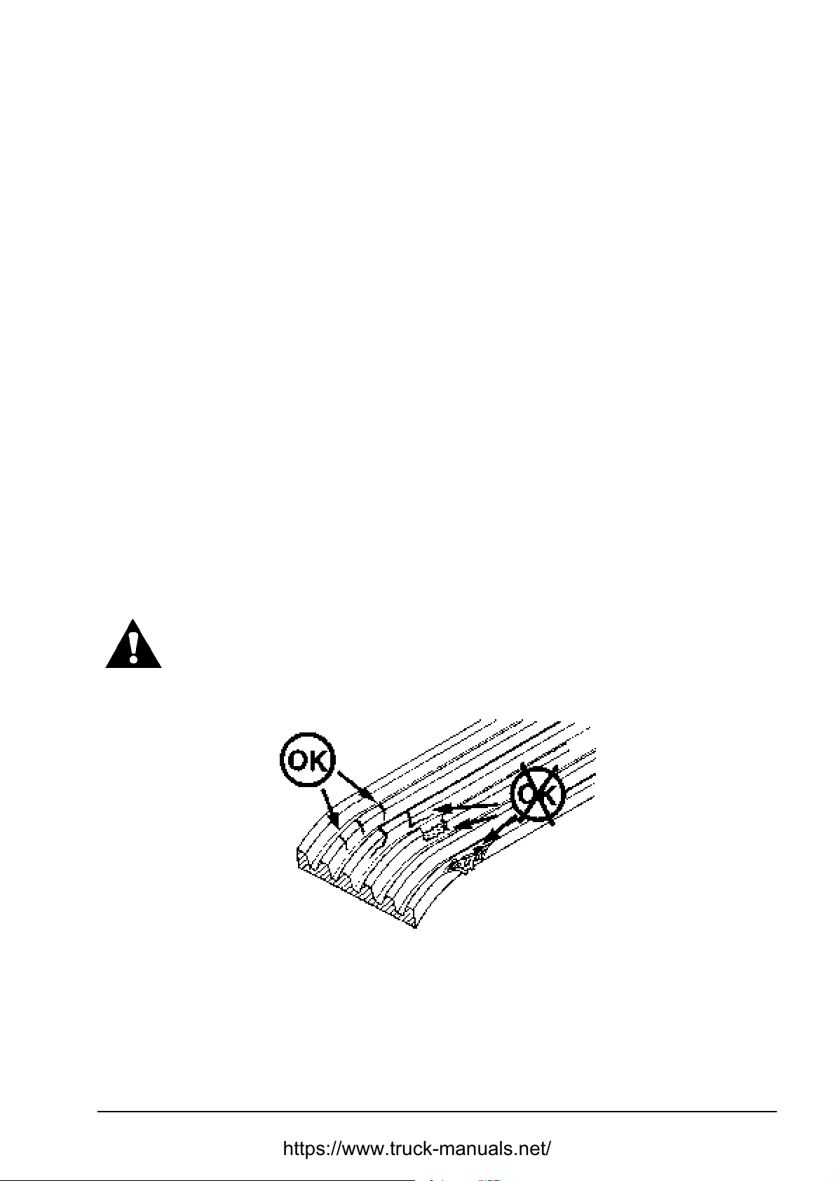
MAINTENANCE SECTION 5
Page 17
AIR CLEANING SYSTEM
Removal (Fig. 5.2.)
Remove the primary element as described in 5.6.2.1.
1.
Unscrew nut (5). Pull safety the element (6) out. Clean the inside of body (7) with a damp cloth.
2.
Check the condition of the gasket at the end of safety element (6). If the gasket is damaged or
missing, replace the element.
Installation (Fig. 5.2.)
1. Install a new safety element (6) into the body (7) and secure it with the nut (5).
2. Install the primary filter element as described in 5.6.2.1.
5.6.3. CHECKING AIR INTAKE SYSTEM FOR LEAKS
Check the air intake system for hose cracks, loose clamps. Tighten loose connection, replace
broken parts to eliminate leaks, which may damage or impair the engine.
NOTE: No leakage is permitted between the air cleaner and the engine intake manifold (the entire
air induction system).
5.7. BELTS
General
WARNING! Keep clear of the fan and fan belt when the engine is running.
Rotating fan and belt contact can cause injury.
5.7.1. Visual Inspection
Fig. 5.3. Belt Inspection
Replace badly worn, greasy or cracked belts immediately. These conditions prevent proper belt
function.
Visually inspect the drive belts for intersecting cracks. Transverse (across the belt width) cracks
are acceptable. Longitudinal (direction of belt length) cracks that intersect with transverse cracks
are not acceptable. Replace a belt if it is frayed or has pieces of material missing.
DRESSTA TD-25H
Page 98
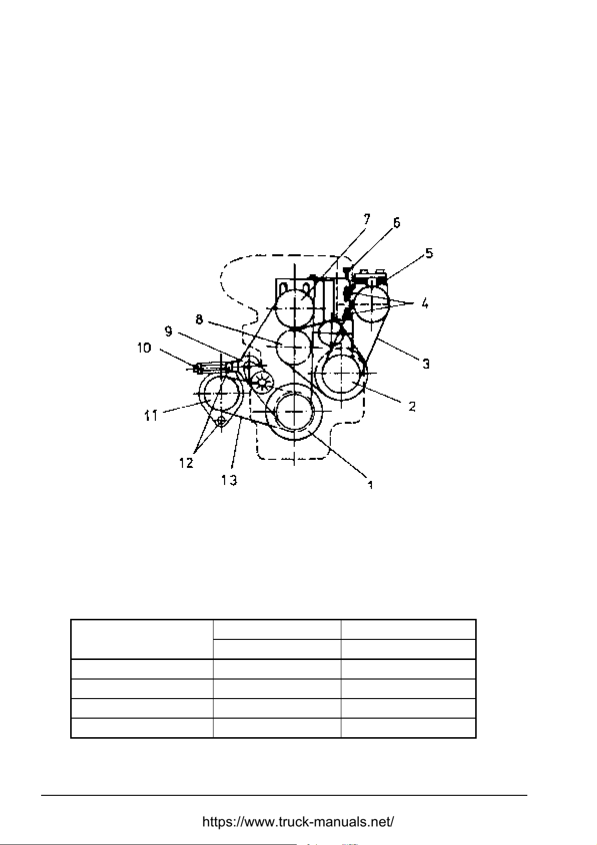
SECTION 5 MAINTENANCE
Page 18
BELTS
5.7.2. CHECKING TENSION AND ADJUSTMENT
Belts on new machines and replacement belts lose their tension as they seat into the pulley
grooves. The tension of the fan, alternator and water pump belts must be checked and adjusted.
Refer to Engine Maintenance Schedule. To check belt tension an ST-1293 Boroughs type gauge
must be used. Adjust the tension according to the „Belt Tension Chart”.
Fig. 5.4. Belt Tension Adjustment
1. Crankshaft pulley
2. A/C Compressor Pulley
3. A/C Compressor Belt
4. Mounting Bolts
5. A/C Compressor
6. A/C Compressor Belt Adjusting Bolt
7. Fan Pulley
8. Water Pump Pulley
9. Fan Belt Tensioner
10. Alternator Belt Adjusting Bo lt
11. Alternator Pulley
12. Alternator Mounting Bolts
13. Alternator Belt
DRIVE NEW BELT TENSION USED BELT TENSION
[N] [N]
ALTERNATOR BELT 620 270 - 490
FAN BELT 620 270 - 490
AIR COMPRESSOR BELT 620 270 - 490
WATER PUMP BELT 710 290 - 580
*
A belt is considered as used after at least 10 minutes of operation
*
TD-25H DRESSTA
Page 99

MAINTENANCE SECTION 5
Page 19
BELTS
5.7.2.1. AIR CONDITIONING COMPRESSOR BELT ADJUSTMENT (Fi g. 5.4)
To adjust belt tension of air conditioning compressor proceed as follows:
1. Loosen mounting bolts (4).
2. Turn in or out the adjusting bolt (6) to increase or decrease belt (3) tension.
3. Tighten mounting bolts (4).
4. Tighten the adjusting bolt (6) with a standard torque.
5.7.2.2. ALTERNATOR BELT ADJUSTMENT (Fig. 5.4)
To adjust belt (13) tension of the air conditioning compressor proceed as follows:
1. Loosen mounting bolts (12).
2. Turn in or out the adjusting bolt (10) to increase or decrease belt tension to the standard value
of 270-490 [N].
3. Tighten mounting bolts (12).
5.7.3. BELT REPLACEMENT
In case of a replacement always inspect all the belts and, if necessary, replace all belts that need
to be replaced. All pulley supports, bearings, shafts, pulleys and brackets must be in working
order. Prior to installing a new belt make sure all pulley grooves are clean and not worn. All
impurities must be removed. If a pulley is damaged or its grooves are worn, it must be replaced.
When replacing belts and pulleys, the pulley alignment must be checked. A misalignment that can
be detected with a naked eye is detrimental to the belt performance.
During a belt installment, do not force the belt into the pulley grooves by prying with a screwdriver
or pry bar. This will damage the belt side cords, which causes the belt to turn and results in
complete destruction of the belt in operation.
5.8. COOLING SYSTEM
General
The cooling system operates under pressure controlled by a pressure relief valve in the radiator
cap. The water pump circulates the coolant through the oil cooler, engine block, cylinder heads,
and radiator. Circulation is controlled by a thermostat, which prevents coolant flow through the
radiator until the engine reaches the operating temperature. Proper cooling is assured only when
the system is sealed, the radiator cap and gasket in good condition, the thermostat operates
properly, the system is free of coolant and/or air flow restrictions and is filled to the proper level.
The selection and maintenance of the system coolant is important to long engine life. The following
information provides recommendations for selecting engine coolant, maint aining coolant inhibit ors,
and servicing the cooling system. This system will operate with a water/antifreeze mixture or
inhibited water as coolant. Never use water alone because water will allow rust, scale deposits,
and corrosion to occur within the system.
DRESSTA TD-25H
Page 100

SECTION 5 MAINTENANCE
Page 20
COOLING SYSTEM
5.8.1. WATER
Use water, which has a low mineral content. Water used in conjunction with antifreeze, coolant
filters and inhibited water must meet the following standards:
Total hardness: Not to exceed 170 parts per million to prevent scale deposits. Water containing
dissolved magnesium and calcium (the usual reason for water hardness) above the specified
amount will cause scale deposits to develop in the engine.
Chlorides – Not to exceed 40 parts per million to prevent corrosion.
Sulfites – Not to exceed 100 parts per million to prevent corrosion.
Dissolved solids – Not to exceed 340 parts per million to minimize sludge deposits, scale
deposits and corrosion.
If any of the requirements cannot be met, use distilled, de-ionized or de-mineralized water. To
determine if local water supplies meet these standards, water treatment laboratories can test water
samples. Softened water that is prepared using common salt (sodium chloride) contains excessive
amounts of chlorides and should not be used.
5.8.2. ANTIFREEZE
Low silicate ethylene glycol antifreeze is recommended. The antifreeze should contain no more
that 0.1% anhydrous alkali metasilicate. Low silicate antifreeze is recommended to avoid the
formation of silica gel (hydro-gel). This gel formation can occur when cooling system contains an
over concentration of high silicate antifreeze and/or supplemental coolant additive. DO NOT use
methanol or alcohol as antifreeze because of its low boiling point. Antifreeze may retain it s freeze
protection for more than one season but coolant conditioners must be added to maintain corrosion
protection. Antifreeze formulated with metoxy propanol, or propylene glycol is not recommended
for this system.
IMPORTANT: Do not mix different types of antifreeze solutions. Mixed solutions make it
impossible to determine the protection against freezing.
IMPORTANT: Antifreeze containing sealer or anti-leak additives should not be used in this system.
Sealer or anti-leak additives will plug the coolant filter and cause plugging problems in the cooling
system.
A table included in Engine Operation and Maintenance Manual shows percentage of antifreeze
concentration required for various temperatures.
5.8.3. INHIBITORS / CONDITIONERS
All cooling system inhibitors, including those in antifreeze solutions, become depleted through
normal operation. If the inhibitors in antifreeze are allowed to become depleted, the antifreeze
becomes corrosive and attacks and coats the metallic surfaces of the cooling system. If the
concentration is too high it causes plugging problems in the cooling system, which reduces heat
transfer. Cooling system conditioners, which contain these inhibitors, must be added or filters
replaced to maintain corrosion protection.
TD-25H DRESSTA
 Loading...