

Page 1

Vii
V
P
o
P
o
European Community Declarations
Manufacturer: DrayTek Corp.
Address: No. 26, Fu Shing Road, HuKou Township, HsinChu Industrial Park, Hsin-Chu, Taiwan 303
Product: VigorSwitch P1100
DrayTek Corp. declares that VigorSwitch P1100 is in compliance with the following essential requirements and other relevant provisions of
2014/30/EU.
The product conforms to the requirements of Electro-Magnetic Compatibility (EMC) Directive 2014/30/EU by complying with the
requirements set forth in EN55022/Class A.
The product conforms to the requirements of Low Voltage (LVD) Directive 2014/35/EU by complying with the requirements set forth in
EN60950-1.
g
g
E
E
W
W
orr
o
8
8
e
e
Quick Start Guide
S
+
+
b
b
S
S
S
wiitt
w
2
2
m
m
Gii
G
c
c
g
arr
a
h
h
a
g
t
t
P
P
biitt
a
b
S
S
wiitt
1
1
w
1
1
0
0
P
P
c
c
0
0
orrtt
o
h
h
s
s
Regulatory Information
Federal Communication Commission Interference Statement
This equipment has been tested and found to comply with the limits for a Class A digital device, pursuant to Part 15 of the FCC Rules. These
limits are designed to provide reasonable protection against harmful interference in a residential installation. This equipment generates, uses
and can radiate radio frequency energy and, if not installed and used in accordance with the instructions, may cause harmful interference to
radio communications. However, there is no guarantee that interference will not occur in a particular installation. If this equipment does cause
harmful interference to radio or television reception, which can be determined by turning the equipment off and on, the user is encouraged to
try to correct the interference by one of the following measures:
Reorient or relocate the receiving antenna.
Increase the separation between the equipment and receiver.
Connect the equipment into an outlet on a circuit different from that to which the receiver is connected.
Consult the dealer or an experienced radio/TV technician for help.
This device complies with Part 15 of the FCC Rules. Operation is subject to the following two conditions:
(1) This device may not cause harmful interference, and
(2) This device may accept any interference received, including interference that may cause undesired operation.
We warrant to the original end user (purchaser) that the switch will be free from any defects in workmanship or materials for a period of one
(1) year from the date of purchase from the dealer.
GPL Notice
This DrayTek product uses software partially or completely licensed under the terms of the GNU GENERAL PUBLIC LICENSE. The author
of the software does not provide any warranty. A Limited Warranty is offered on DrayTek products. This Limited Warranty does not cover
any software applications or programs.
To download source codes please visit:
http://gplsource.draytek.com
GNU GENERAL PUBLIC LICENSE:
https://gnu.org/licenses/gpl-2.0
Version 2, June 1991
For any question, please feel free to contact DrayTek technical support at support@draytek.com for further information.
Version: 1.4
Date: February 7, 2017
Page 2
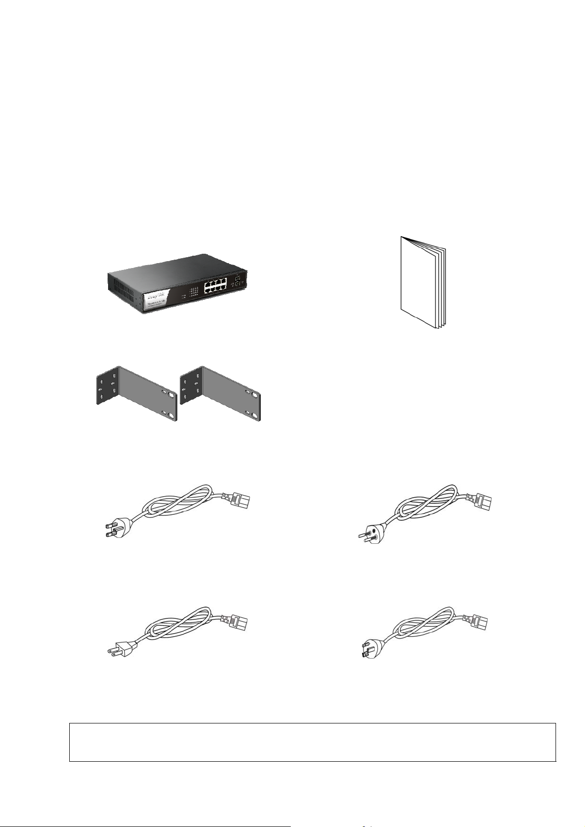
Package Content
The PoE 8 + 2 Gigabit Ports Web Smart Switch is a standard switch that
meets both IEEE 802.3u/ab Fast Ethernet and Gigabit Ethernet specifications.
The switch has 8 Gigabit Ethernet ports plus 2 SFP fiber ports.
The network administrator can logon the switch to monitor, configure and
control each port’s activity. In addition, the switch implements the QoS
(Quality of Service) and VLAN. It is suitable for office application.
VigorSwitch
Rack mount kit (brackets)
Quick Start Guide
UK-type power cord
USA/Taiwan-type power cord
Note: If any of these items is found missing or damaged, please contact
your local supplier for replacement.
EU-type power cord
AU/NZ-type power cord
Page 3

Descriptions of Panel
LED Status Explanation
On (Green) The device is powered on. PWR
Off The device is powered off.
On (Green) The switch finishes system booting.
SYS
Blinking
(Green)
Off
The switch is powered on and starts system
booting.
The power is off or the system is not ready /
malfunctioning.
ACT
(Port
1~10)
Interface Description
On (Green) Port is connected at 1000 Mps.
Off LAN is disconnected.
Blinking
(Green)
On (Green) A Power Device is connected. PoE
Off No Power Device is connected.
Power inlet for AC input (100~240V/AC, 50/60Hz).
1/0 (ON/OFF) - Power switch.
Data is transmitting (sending/receiving).
Power Output -- IEEE 802.3af Max. 15.4W Output Supported;
IEEE 802.3at Max. 30W Output Supported
PoE Power Budget -- 110 Watts (Max)
Page 4

Installing Your Switch
Power Device to This Switch and Getting 48V Power Source through
Cat. 5e Cable
Use a Cat. 5e twisted-pair cable to connect a PoE device to the port (1~8) of this
switch. The switch will supply power to PoE Device over the twisted-pair cable.
Please note that Power Device must comply with IEEE 802.3af/at. Other PCs,
servers and network devices can be connected to the switch using a standard
‘straight through’ twisted pair cable.
The switch can be installed
easily by using rack mount
kit. However, due to
environmental limitation,
the wall-mount installation
might be required. Simply
follow the steps below:
1. The two slots located on
the switch’s bottom
panel are for device
wall-mount use. The
distance between the two
slots is 7.8 inches
(198.02 mm). Attach two
screws on the wall, so
that the switch’s
wall-mount slots line up
with the two screws.
2. Use drill bit to insert the two
plastic screws into the wall.
3. Insert the two iron screws into the
hole of the two plastic screws
respectively.
4. Place the switch onto the iron
screws through the wall-mount
slots to make the switch hanging
on the wall.
 Loading...