

Page 1

i
Page 2

VigorSwitch P1100
PoE 8 + 2 Gigabit Port Web Smart
Switch
User’s Guide
Version: 1.4
Firmware Version: V2.1.0_RC1
Date: January 5, 2018
(For future update, please visit DrayTek web site for further information)
ii
VigorSwitch P1100 User’s Guide
Page 3

Intellectual Property Rights (IPR) Information
Copyrights
Trademarks
© All rights reserved. This publication contains information that is protected by
copyright. No part may be reproduced, transmitted, transcribed, stored in a
retrieval system, or translated into any language without written permission from
the copyright holders.
The following trademarks are used in this document:
Microsoft is a registered trademark of Microsoft Corp.
Windows, Windows 95, 98, Me, NT, 2000, XP, 7 and Explorer are
trademarks of Microsoft Corp.
Apple and Mac OS are registered trademarks of Apple Inc.
Other products may be trademarks or registered trademarks of their
respective manufacturers.
Caution and Electronic Emission Notices
Caution
Warranty
Circuit devices are sensitive to static electricity, which can damage their delicate
electronics. Dry weather conditions or walking across a carpeted floor may cause you
to acquire a static electrical charge.
To protect your device, always:
Touch the metal chassis of your computer to ground the static electrical charge
before you pick up the circuit device.
Pick up the device by holding it on the left and right edges only.
We warrant to the original end user (purchaser) that the device will be free from any
defects in workmanship or materials for a period of one (1) years from the date of
purchase from the dealer. Please keep your purchase receipt in a safe place as it
serves as proof of date of purchase. During the warranty period, and upon proof of
purchase, should the product have indications of failure due to faulty workman s hip
and/or materials, we will, at our discretion, repair or replace the defective products or
components, without charge for either parts or labor, to whatever extent we deem
necessary tore-store the product to proper operating condition. Any replacement will
consist of a new or re-manufactured functionally equivalent product of equal value,
and will be offered solely at our discretion. This warranty will not apply if the
product is modified, misused, tampered with, damaged by an act of God, or subjected
to abnormal working conditions. The warranty does not cover the bun dled or licensed
software of other vendors. Defects which do not significantly affect the usability of
the product will not be covered by the warranty. We reserve the right to revise the
manual and online documentation and to make changes from time to time in the
contents hereof without obligation to notify any person of such revision or changes.
Be a Registered
Owner
Firmware & Tools
Updates
Web registration is preferred. You can register your Vigor device via
http://www.draytek.com.
Due to the continuous evolution of DrayTek technology, all devices will be regularly
upgraded. Please consult the DrayTek web site for more information on newest
firmware, tools and documents.
http://www.draytek.com
VigorSwitch P1100 User’s Guide
iii
Page 4

European Community Declarations
Manufacturer: DrayTek Corp.
Address: No. 26, Fu Shing Road, HuKou township, HsinChu Industrial Park, Hsin-Chu, Taiwan 303
Product: VigorSwitch Series Device
The product conforms to the requirements of Electro-Magnetic Compatibility (EMC) Directive 2004/108/EC by
complying with the requirements set forth in EN55022/Class A and EN55024/Class A.
The product conforms to the requirements of Low Voltage (LVD) Directive 2006/95/EC by complying with the
requirements set forth in EN6095-1.
Federal Communications Commission (FCC) Statement
This equipment has been tested and found to comply with the limits for a class A computing device pursuant to
Subpart J of part 15 of FCC Rules, which are designed to provide reasonable protection against such interference
when operated in a commercial environment.
All trade names and trademarks are the properties of their respective companies.
GPL Notice
This DrayTek product uses software partial ly or completely licensed under the terms of the GNU GENERAL
PUBLIC LICENSE. The author of the software does not provide any warranty. A Limited Warranty is offered on
DrayTek products. This Limited Warranty does not cover any software applications or programs.
To download source codes please visit:
http://gplsource.draytek.com
GNU GENERAL PUBLIC LICENSE:
https://gnu.org/licenses/gpl-2.0
Version 2, June 1991
For any question, please feel free to contact DrayTek technical support at support@draytek.com for further
information.
iv
VigorSwitch P1100 User’s Guide
Page 5

TTaabbllee ooff CCoonntteennttss
Chapter 1: Introduction.....................................................................................................1
1.1 Overview................................................................................................................................. 1
1.2 Features.................................................................................................................................. 1
1.3 Packing List............................................................................................................................. 2
1.4 LED Indicators and Connectors.............................................................................................. 3
1.5 Hardware Installation .............................................................................................................. 4
1.5.5 Configuring the Management Agent of Switch................................................................. 8
1.5.6 IP Address Assignment .................................................................................................... 9
1.6 Typical Applications............................................................................................................... 13
Chapter 2: Basic Concept and Management.................................................................15
2.1 What’s the Ethernet............................................................................................................... 15
2.2 Media Access Control (MAC)................................................................................................ 17
2.3 Flow Control.......................................................................................................................... 22
Chapter 3: Operation of Web-based Management........................................................25
3.1 Web Management Home Overview...................................................................................... 26
3.2 Status.................................................................................................................................... 27
3.2.1 System Information......................................................................................................... 27
3.2.2 Logging Message ...........................................................................................................28
3.2.3 Port .................................................................................................................................29
3.2.4 Link Aggregation............................................................................................................. 31
3.2.5 MAC Address Table........................................................................................................ 32
3.2.6 PoE Status...................................................................................................................... 32
3.2.7 LLDP Statistics ............................................................................................................... 33
3.2.8 IGMP Statistics............................................................................................................... 34
3.3 Network................................................................................................................................. 36
3.3.1 IP Address...................................................................................................................... 36
3.3.2 System Time................................................................................................................... 38
3.4 Switching............................................................................................................................... 40
3.4.1 Port Setting..................................................................................................................... 40
3.4.2 Link Aggregation............................................................................................................. 43
3.4.3 EEE................................................................................................................................. 49
3.4.4 Jumbo Frame.................................................................................................................. 51
3.4.5 PoE................................................................................................................................. 52
3.4.6 VLAN Management ........................................................................................................ 55
3.4.7 Multicast.......................................................................................................................... 63
3.4.8 Spanning Tree................................................................................................................ 71
3.5 MAC Address Table............................................................................................................... 76
3.5.1 Dynamic Address............................................................................................................ 76
3.5.2 Static Address................................................................................................................. 77
3.6 Security ................................................................................................................................. 79
3.6.1 Access Control................................................................................................................ 79
3.6.2 Protected Port................................................................................................................. 80
3.6.3 Storm Control.................................................................................................................. 81
3.6.4 DoS................................................................................................................................. 83
VigorSwitch P1100 User’s Guide
v
Page 6

3.7 QoS....................................................................................................................................... 88
3.7.1 General........................................................................................................................... 88
3.7.2 Rate Limit........................................................................................................................ 95
3.8 Management......................................................................................................................... 99
3.8.1 LLDP............................................................................................................................... 99
3.8.2 SNMP............................................................................................................................ 107
3.9 Diagnostics...........................................................................................................................111
3.9.1 Logging......................................................................................................................... 111
3.9.2 Mirroring........................................................................................................................ 113
3.9.3 Ping............................................................................................................................... 115
3.9.4 Copper Test.................................................................................................................. 116
3.10 Maintenance.......................................................................................................................116
3.10.1 User Account.............................................................................................................. 116
3.10.2 Firmware Upgrade/Backup......................................................................................... 117
3.10.3 Configuration .............................................................................................................. 119
3.10.4 Factory Default / System Reboot................................................................................ 121
Chapter 4: Trouble Shooting.........................................................................................123
4.1 Resolving No Link Condition............................................................................................... 123
4.2 Q & A................................................................................................................................... 123
vi
VigorSwitch P1100 User’s Guide
Page 7

Chhaapptteerr 11:: IInnttrroodduuccttiioonn
C
11..11 OOvveerrvviieeww
PoE 8+2 Gigabit Ports Web Smart Switch is a standard switch that meets all IEEE
802.3/u/x/z Gigabit, Fast Ethernet specifications. The switch supports console, telnet, http
and SNMP interface for switch management. The network administrator can logon the
switch to monitor, configure and control each port’s activity. In addition, the switch
implements the QoS (Quality of Service), VLAN, and Trunking. It is suitable for office
application.
Others the switch increases support the Power saving for reduce the power consumption
with "ActiPHY Power Management" and "PerfectReach Power Management" two
techniques. It could efficient saving the switch power with auto detect the client idle and
cable length to provide different power.
10/100/1000Mbps TP is a standard Ethernet port that meets all IEEE 802.3/u/x/z Gigabit,
Fast Ethernet specifications. 1000Mbps SFP Fiber transceiver is a Gigabit Ethernet port
that fully complies with all IEEE 802.3z and 1000Base-SX/LX standards.
Below shows key features of this device:
QQooSS
The switch offers powerful QoS function. This function supports 802.1p VLAN tag priority
and DSCP on Layer 3 of network framework.
VVLLAANN
Support Port-based VLAN and IEEE802.1Q Tag VLAN. Support 24 active VLANs and
VLAN ID 1~4094.
PPoorrtt TTrruunnkkiinngg
Allows one or more links to be aggregated together to form a Link Aggregation Group by
the static setting.
PPoowweerr SSaavviinngg
The Power saving using the "ActiPHY Power Management" and "PerfectReach Power
Management" two techniques to detect the client idle and cable length automatically and
provides the different power. It could efficient to save the switch power and reduce the
power consumption.
11..22 FFeeaattuurreess
The VigorSwitch P1100, a standalone off-the-shelf switch, provides the comprehensive
features listed below for users to perform system network administration and efficiently
and securely serve your network.
HHaarrddwwaarree
8 10/100/1000Mbps Auto-negotiation Gigabit Ethernet TP ports
512KB on-chip frame buffer
VigorSwitch P1100 User’s Guide
1
Page 8

Jumbo frame support 9KB
Programmable classifier for QoS (Layer 2/Layer 3)
8K MAC address and support VLAN ID(1~4094)
Per-port shaping, policing, and Broadcast Storm Control
Power Saving with "ActiPHY Power Management" and "Perfect Reach Power
Management" techniques.
IEEE802.1ad Q-in-Q nested VLAN support
Full-duplex flow control (IEEE802.3x) and half-duplex backpressure
Extensive front-panel diagnostic LEDs; System: Power, TP Port1-24: LINK/ACT,
10/100/1000Mbps
MMaannaaggeemmeenntt
Supports per port traffic monitoring counters
Supports a snapshot of the system Information when you login
Supports port mirror function
Supports the static trunk function
Supports 802.1Q VLAN
Supports user management and limits three users to login
Maximal packet length can be up to 9600 bytes for jumbo frame application
Supports Broadcasting Suppression to avoid network suspended or crashed
Supports to send the trap event while monitored events happened
Supports default configuration which can be restored to overwrite the current
configuration which is working on via Web UI and Reset button of the switch
Supports on-line plug/unplug SFP modules
Supports Quality of Service (QoS) for real time applications based on the
information taken from Layer 2 to Layer 3
Built-in web-based management and CLI management, providing a more
convenient UI for the user
11..33 PPaacckkiinngg LLiisstt
Before you start installing the switch, verify that the package contains the following:
VigorSwitch P1100
AC
Quick Start Guide
Rubber feet
Rack mount kit
Please notify your sales representative immediately if any of the aforementioned items is
missing or damaged.
Power Cord
2
VigorSwitch P1100 User’s Guide
Page 9

11..44 LLEEDD IInnddiiccaattoorrss aanndd CCoonnnneeccttoorrss
Before you use the Vigor device, please get acquainted with the LED indicators and
connectors first.
There are 8 Ethernet ports on the front panel of the switch. LED display area, locating on
the front panel, contains an ACT, Power LED and 8 ports working status of the switch.
LLEEDD EExxppllaannaattiioonn
LED Color Explanation
PWR
SYS
ACT (Port
1~10)
On (Green) The device is powered on.
Off The device is powered off.
On (Green) The switch finishes system booting.
Blinking
(Green)
Off
On (Green) Port is connected at 1000 Mps.
Off
Blinking
(Green)
On (Green) A Power Device is connected. PoE
Off No Power Device is connected.
The switch is powered on and starts system
booting.
The power is off or the system is not ready /
malfunctioning.
LAN is disconnected.
Data is transmitting (sending/receiving).
CCoonnnneeccttoorr EExxppllaannaattiioonn
Interface Description
Power inlet for AC input (100~240V/AC, 50/60Hz).
1/0 (ON/OFF) - Power switch.
Power Output -- IEEE 802.3af Max. 15.4W Output Supported;
IEEE 802.3at Max. 30W Output Supported
PoE Power Budget -- 130 Watts (Max)
VigorSwitch P1100 User’s Guide
3
Page 10
UUsseerr IInntteerrffaacceess oonn tthhee RReeaarr PPaanneell
8-PORT GBE WEB SMART SWITCH
11..55 HHaarrddwwaarree IInnssttaallllaattiioonn
Case 1: All switch ports are in the same local area network.
Every port can access each other. (*The switch image is sample only.)
(
If VLAN is enabled and configured, each node in the network that can communicate each
other directly is bounded in the same VLAN area.
Here VLAN area is defined by what VLAN you are using. The switch supports both
port-based VLAN and tag-based VLAN. They are different in practical deployment,
especially in physical location. The following diagram shows how it works and what the
difference they are.
4
VigorSwitch P1100 User’s Guide
Page 11
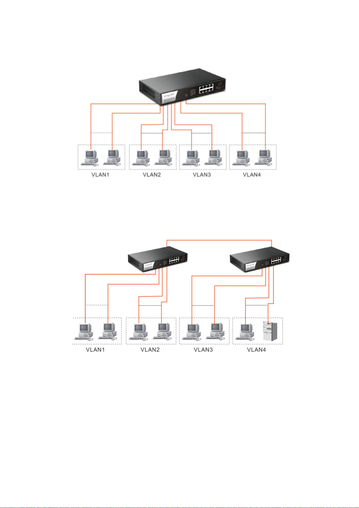
Case 2: Port-based VLAN -1 (*The switch image is sample only.)
The same VLAN members could not be in different switches.
Every VLAN members could not access VLAN members each other.
The switch manager has to assign different names for each VLAN groups at one
switch.
Case 3: Port-based VLAN - 2
VLAN1 members could not access VLAN2, VLAN3 and VLAN4 members.
VLAN2 members could not access VLAN1 and VLAN3 members, but they could
access VLAN4 members.
VLAN3 members could not access VLAN1, VLAN2 and VLAN4.
VLAN4 members could not access VLAN1 and VLAN3 members, but they could
access VLAN2 members.
VigorSwitch P1100 User’s Guide
5
Page 12
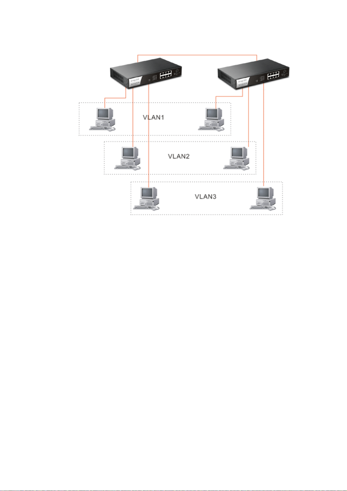
Case 4: The same VLAN members can be at different switches with the same VID
DDeesskkttoopp IInnssttaallllaattiioonn
1. Install the switch on a level surface that can support the weight of the unit and the
relevant components.
2. Plug the switch with the female end of the provided power cord and plug the male
end to the power outlet.
RRaacckk--mmoouunntt IInnssttaallllaattiioonn
The switch may be standalone, or mounted in a rack. Rack mounting facilitate to an orderly
installation when you are going to install series of networking devices.
Procedures to Rack-mount the switch:
1. Disconnect all the cables from the switch before continuing.
2. Place the unit the right way up on a hard, flat surface with the front facing you.
3. Locate a mounting bracket over the mounting holes on one side of the unit.
4. Insert the screws and fully tighten with a suitable screwdriver.
5. Repeat the two previous steps for the other side of the unit.
6. Insert the unit into the rack and secure with suitable screws.
7. Reconnect all the cables.
6
VigorSwitch P1100 User’s Guide
Page 13

IInnssttaalllliinngg NNeettwwoorrkk CCaabblleess
Crossover or straight-through cable: All the ports on the switch support
Auto-MDI/MDI-X functionality. Both straight-through or crossover cables can be used
as the media to connect the switch with PCs as well as other devices like switches, hubs
or router.
Category 3, 4, 5 or 5e, 6 UTP/STP cable: To make a valid connection and obtain the
optimal performance, an appropriate cable that corresponds to different
transmitting/receiving speed is required. To choose a suitable cable, please refer to the
following table.
Media Speed Wiring
10 Mbps Category 3,4,5 UTP/STP
10/100/1000
Mbps copper
100Mbps Category 5 UTP/STP
1000 Mbps Category 5e, 6 UTP/STP
VigorSwitch P1100 User’s Guide
7
Page 14
11..55..55 CCoonnffiigguurriinngg tthhee MMaannaaggeemmeenntt AAggeenntt ooff SSwwiittcchh
Users can monitor and configure the switch through the following procedures.
Configuring the Management Agent of VigorSwitch P1100 through the Ethernet Port.
There are two ways to configure and monitor the switch through the switch’s Ethernet port.
They are Web browser and SNMP manager. We just introduce the first type of
management interface. Web-based UI for the switch is an interface in a highly friendly
way.
Managing VigorSwitch P1100 through Ethernet Port
Before start using the switch, the IP address setting of the switch should be done, then
perform the following steps:
1. Set up a physical path between the configured the switch and a PC by a qualified UTP
Cat. 5 cable with RJ-45 connector.
Note: If PC directly connects to the switch, you have to setup the same subnet mask
between them. But, subnet mask may be different for the PC in the remote site.
Please refer to the above figure about the 24-Port GbE Web Smart Switch default IP
address information.
2. Run web browser and follow the menu. Please refer to Chapter 3.
8
VigorSwitch P1100 User’s Guide
Page 15
11..55..66 IIPP AAddddrreessss AAssssiiggnnmmeenntt
For IP address configuration, there are three parameters needed to be filled in. They are IP
address, Subnet Mask, Default Gateway and DNS.
IP address:
The address of the network device in the network is used for internetworking
communication. Its address structure looks is shown below. It is “classful” because it is
split into predefined address classes or categories.
Each class has its own network range between the network identifier and host identifier in
the 32 bits address. Each IP address comprises two parts: network identifier (address) and
host identifier (address). The former indicates the network where the addressed host resides,
and the latter indicates the individual host in the network which the address of host refers to.
And the host identifier must be unique in the same LAN. Here the term of IP address we
used is version 4, known as IPv4.
Network identifier Host identifier
32 bits
With the classful addressing, it divides IP address into three classes, class A, class B and
class C. The rest of IP addresses are for multicast and broadcast. The bit length of the
network prefix is the same as that of the subnet mask and is denoted as IP address/X, for
example, 192.168.1.0/24. Each class has its address range described below.
Class A:
Address is less than 126.255.255.255. There are a total of 126 networks can be defined
because the address 0.0.0.0 is reserved for default route and 127.0.0.0/8 is reserved for
loopback function.
Class B:
VigorSwitch P1100 User’s Guide
9
Page 16
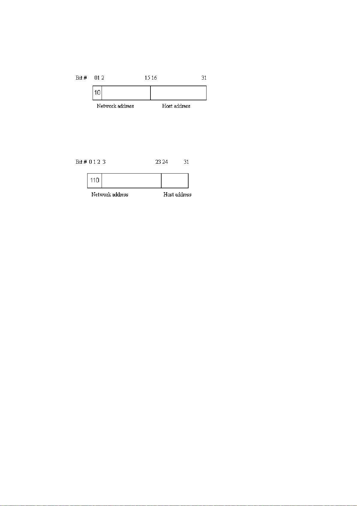
IP address range between 128.0.0.0 and 191.255.255.255. Each class B network has a
16-bit network prefix followed 16-bit host address. There are 16,384 (2^14)/16 networks
able to be defined with a maximum of 65534 (2^16 –2) hosts per network.
Class C:
IP address range between 192.0.0.0 and 223.255.255.255. Each class C network has a
24-bit network prefix followed 8-bit host address. There are 2,097,152 (2^21)/24 networks
able to be defined with a maximum of 254 (2^8 –2) hosts per network.
Class D and E:
Class D is a class with first 4 MSB (Most significance bit) set to 1-1-1-0 and is used for IP
Multicast. See also RFC 1112. Class E is a class with first 4 MSB set to 1-1-1-1 and is used
for IP broadcast.
According to IANA (Internet Assigned Numbers Authority), there are three specific IP
address blocks reserved and able to be used for extending internal network. We call it
Private IP address and list below:
Class A 10.0.0.0 --- 10.255.255.255
Class B 172.16.0.0 --- 172.31.255.255
Class C 192.168.0.0 --- 192.168.255.255
Please refer to RFC 1597 and RFC 1466 for more information.
Subnet mask:
It means the sub-division of a class-based network or a CIDR block. The subnet is used to
determine how to split an IP address to the network prefix and the host address in bitwise
basis. It is designed to utilize IP address more efficiently and ease to manage IP network.
For a class B network, 128.1.2.3, it may have a subnet mask 255.255.0.0 in default, in
which the first two bytes is with all 1s. This means more than 60 thousands of nodes in flat
IP address will be at the same network. It’s too large to manage practically. Now if we
divide it into smaller network by extending network prefix from 16 bits to, say 24 bits,
that’s using its third byte to subnet this class B network. Now it has a subnet mask
255.255.255.0, in which each bit of the first three bytes is 1. It’s now clear that the first two
bytes is used to identify the class B network, the third byte is used to identify the subnet
within this class B network and, of course, the last byte is the host number.
Not all IP address is available in the sub-netted network. Two special addresses are
reserved. They are the addresses with all zero’s and all one’s host number. For example, an
IP address 128.1.2.128, what IP address reserved will be looked like? All 0s mean the
network itself, and all 1s mean IP broadcast.
10
VigorSwitch P1100 User’s Guide
Page 17

In this diagram, you can see the subnet mask with 25-bit long, 255.255.255.128, contains
126 members in the sub-netted network. Another is that the length of network prefix equals
the number of the bit with 1s in that subnet mask. With this, you can easily count the
number of IP addresses matched. The following table shows the result.
Prefix Length No. of IP matched No. of Addressable IP
/32 1 /31 2 /30 4 2
/29 8 6
/28 16 14
/27 32 30
/26 64 62
/25 128 126
/24 256 254
/23 512 510
/22 1024 1022
/21 2048 2046
/20 4096 4094
/19 8192 8190
/18 16384 16382
/17 32768 32766
/16 65536 65534
According to the scheme above, a subnet mask 255.255.255.0 will partition a network with
the class C. It means there will have a maximum of 254 effective nodes existed in this
sub-netted network and is considered a physical network in an autonomous network. So it
owns a network IP address which may looks like 168.1.2.0.
With the subnet mask, a bigger network can be cut into small pieces of network. If we want
to have more than two independent networks in a worknet, a partition to the network must
be performed. In this case, subnet mask must be applied.
For different network applications, the subnet mask may look like 255.255.255.240. This
means it is a small network accommodating a maximum of 15 nodes in the network.
VigorSwitch P1100 User’s Guide
11
Page 18
Default gateway:
For the routed packet, if the destination is not in the routing table, all the traffic is put into
the device with the designated IP address, known as default router. Basically, it is a routing
policy. The gateway setting is used for Trap Events Host only in the switch.
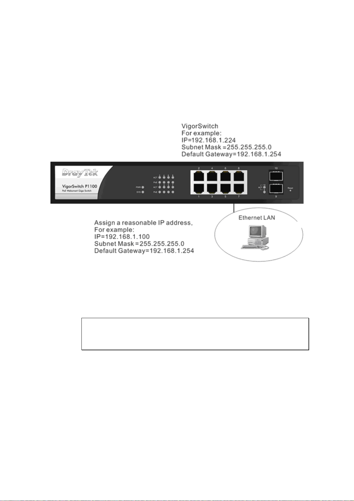
For assigning an IP address to the switch, you just have to check what the IP address of the
network will be connected with the switch. Use the same network address and append your
host address to it.
First, IP Address: as shown above, enter “192.168.1.224”, for instance. For sure, an IP
address such as 192.168.1.x must be set on your PC.
Second, Subnet Mask: as shown above, enter “255.255.255.0”. Any subnet mask such as
255.255.255.x is allowable in this case.
: The DHCP Setting is enabled in default.
Note
12
VigorSwitch P1100 User’s Guide
Page 19
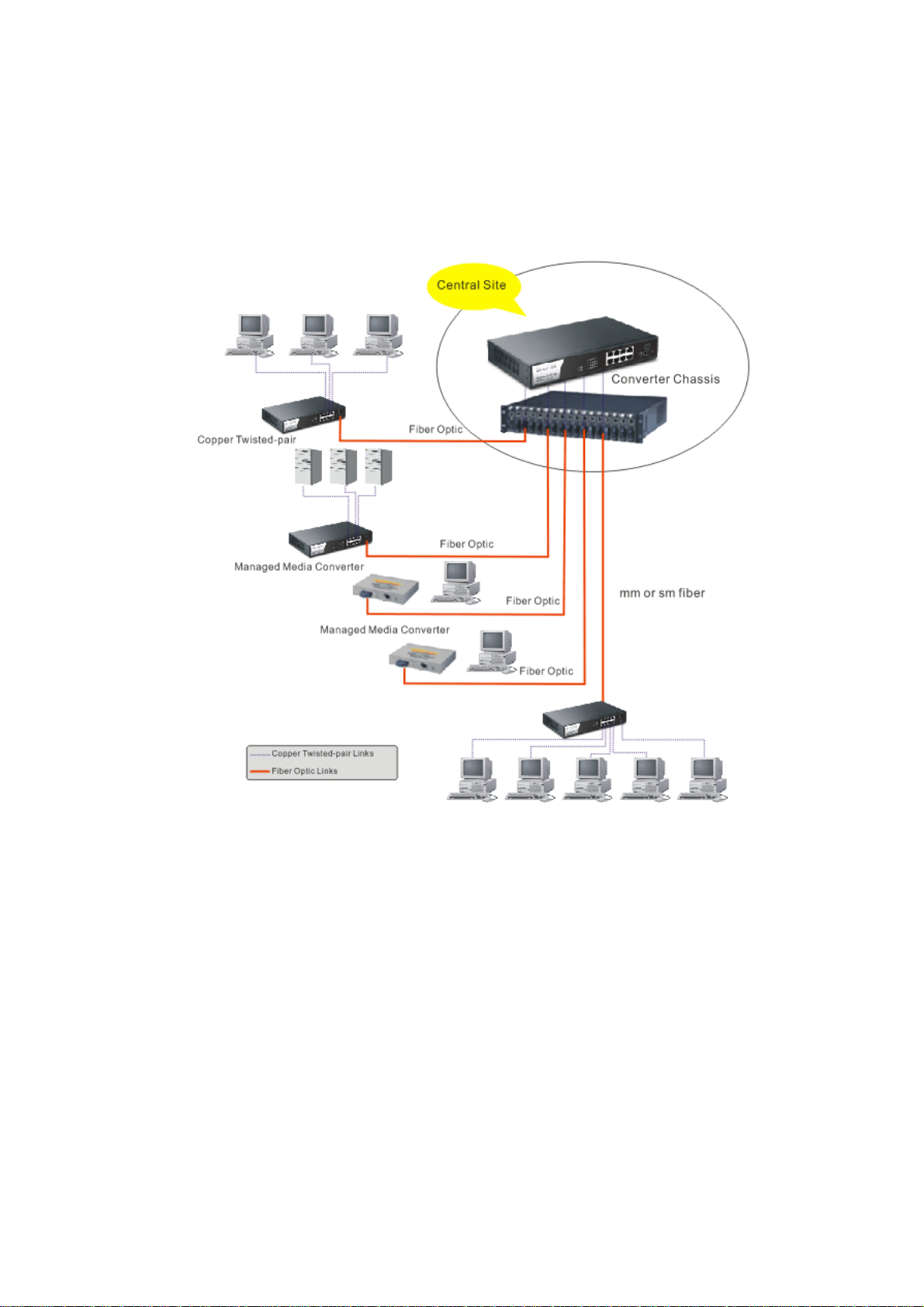
11..66 TTyyppiiccaall AApppplliiccaattiioonnss
The VigorSwitch implements 8 Gigabit Ethernet TP ports with auto MDIX and two slots
for the removable module supporting comprehensive fiber types of connection including
LC and BiDi-LC SFP modules. The switch is suitable for the following applications.
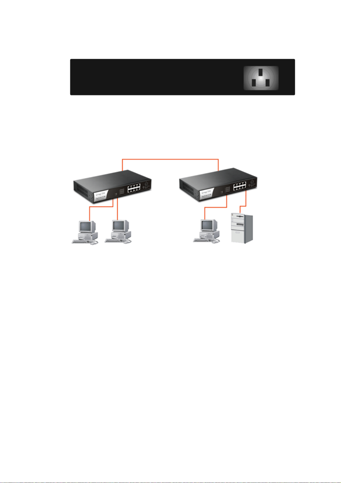
Central Site/Remote site application is used in carrier or ISP
VigorSwitch P1100 User’s Guide
13
Page 20
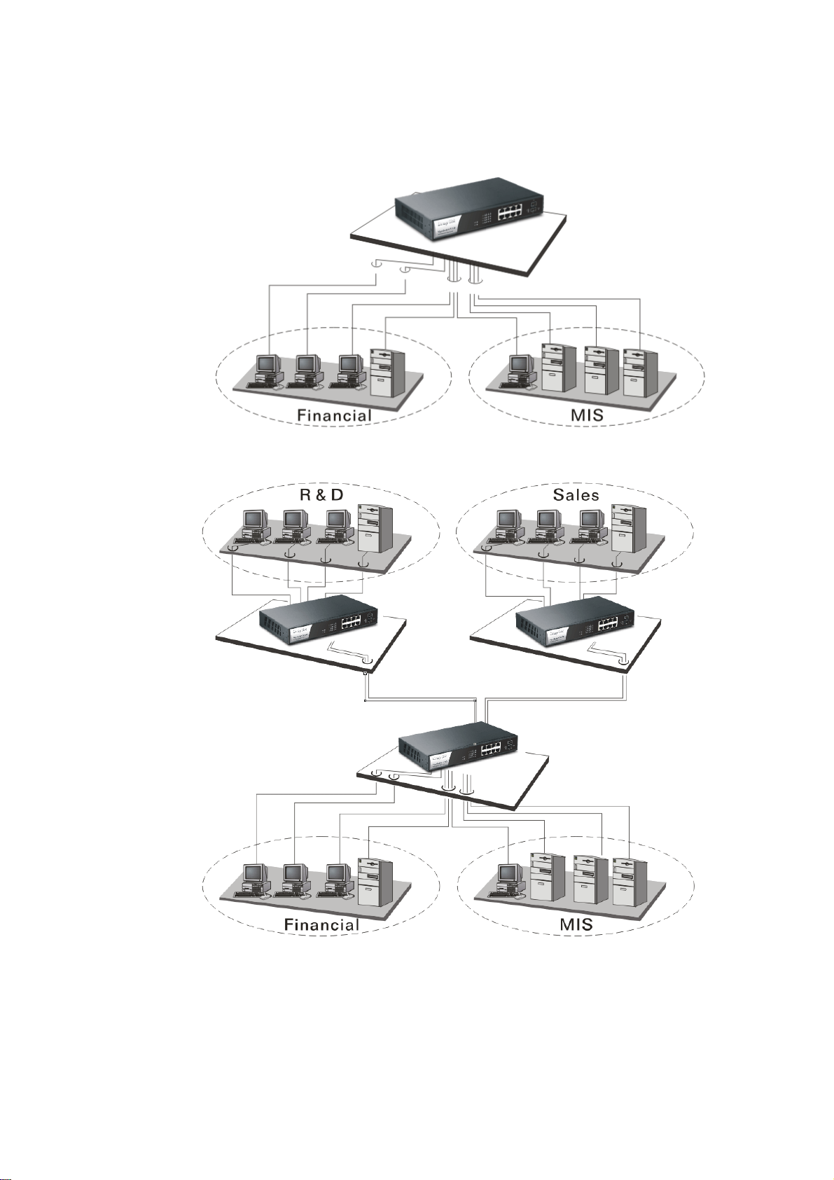
It is a system wide basic reference connection diagram. This diagram demonstrates how the
switch connects with other network devices and hosts.
Peer-to-peer application is used in two remote offices
Office network
14
VigorSwitch P1100 User’s Guide
Page 21
Chhaapptteerr 22::
C
Maannaaggee
M
This chapter will tell you the basic concept of features to manage this switch and how they
work.
22..11 WWhhaatt’’ss tthhee EEtthheerrnneett
Ethernet originated and was implemented at Xerox in Palo Alto, CA in 1973 and was
successfully commercialized by Digital Equipment Corporation (DEC), Intel and Xerox
(DIX) in 1980. In 1992, Grand Junction Networks unveiled a new high speed Ethernet with
the same characteristic of the original Ethernet but operated at 100Mbps, called Fast
Ethernet now. This means Fast Ethernet inherits the same frame format, CSMA/CD,
software interface. In 1998, Gigabit Ethernet was rolled out and provided 1000Mbps. Now
10G/s Ethernet is under approving. Although these Ethernet have different speed, they still
use the same basic functions. So they are compatible in software and can connect each
other almost without limitation. The transmission media may be the only problem.
Baassiicc
B
meenntt
m
Coonncceepptt aanndd
C
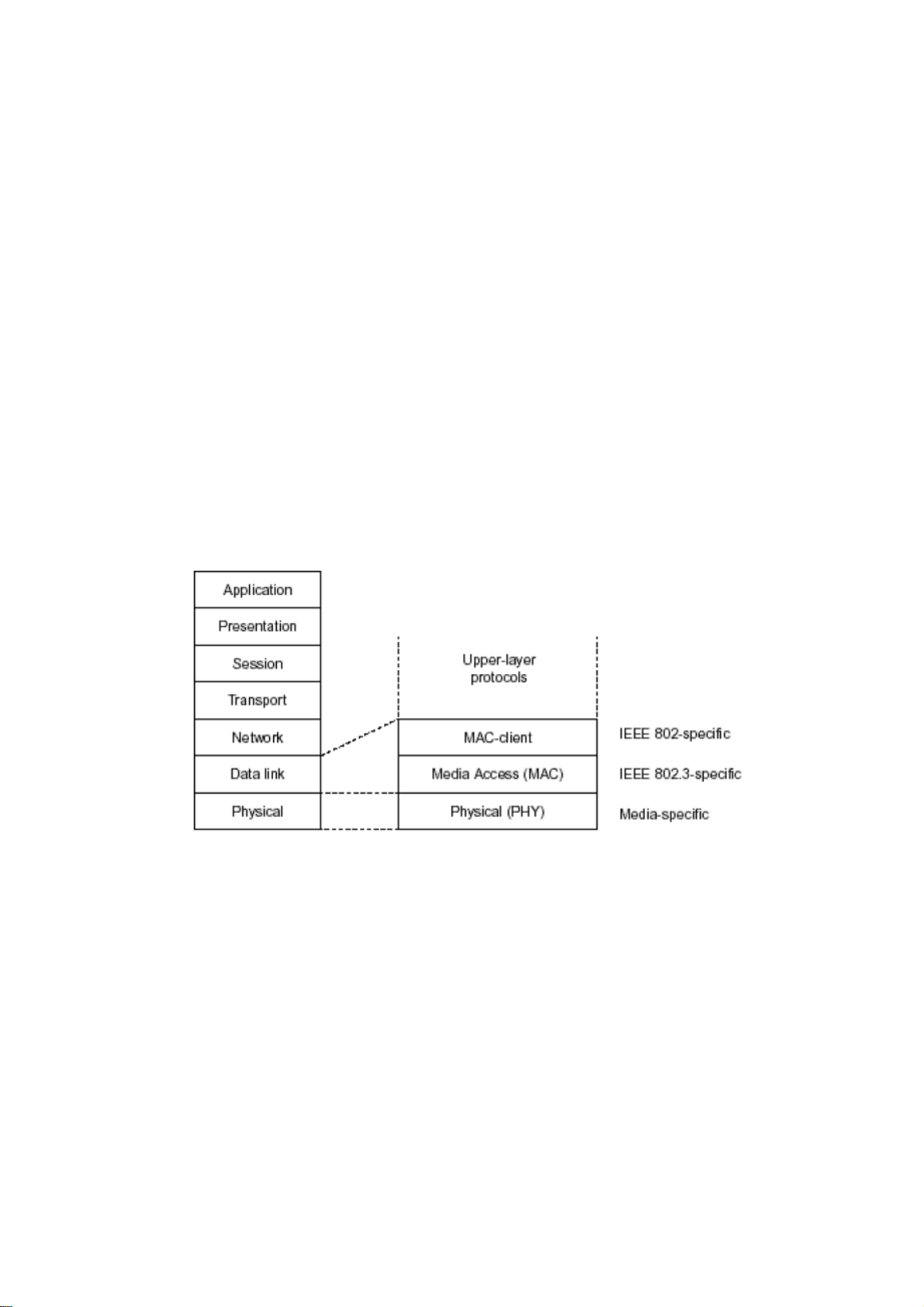
In the above figure, we can see that Ethernet locates at the Data Link layer and Physical
layer and comprises three portions, including logical link control (LLC), media access
control (MAC), and physical layer. The first two comprises Data link layer, which
performs splitting data into frame for transmitting, receiving acknowledge frame, error
checking and re-transmitting when not received correctly as well as provides an error-free
channel upward to network layer.
VigorSwitch P1100 User’s Guide
15
Page 22
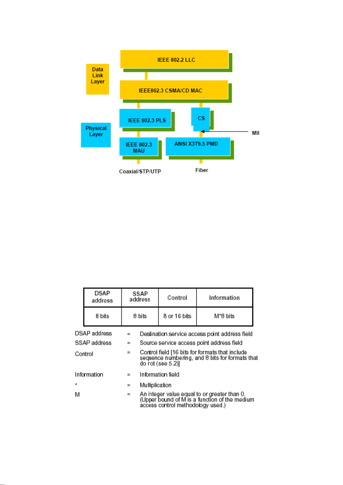
This above diagram shows the Ethernet architecture, LLC sub-layer and MAC sub-layer,
which are responded to the Data Link layer, and transceivers, which are responded to the
Physical layer in OSI model. In this section, we are mainly describing the MAC sub-layer.
LLooggiiccaall LLiinnkk CCoonnttrrooll ((LLLLCC))
Data link layer is composed of both the sub-layers of MAC and MAC-client. Here MAC
client may be logical link control or bridge relay entity.
Logical link control supports the interface between the Ethernet MAC and upper layers in
the protocol stack, usually Network layer, which is nothing to do with the nature of the
LAN. So it can operate over other different LAN technology such as Token Ring, FDDI
and so on. Likewise, for the interface to the MAC layer, LLC defines the services with the
interface independent of the medium access technology and with some of the nature of the
medium itself.
The table above is the format of LLC PDU. It comprises four fields, DSAP, SSAP, Control
and Information. The DSAP address field identifies the one or more service access points,
in which the I/G bit indicates it is individual or group address. If all bit of DSAP is 1s, it’s a
global address. The SSAP address field identifies the specific services indicated by C/R bit
16
VigorSwitch P1100 User’s Guide
Page 23
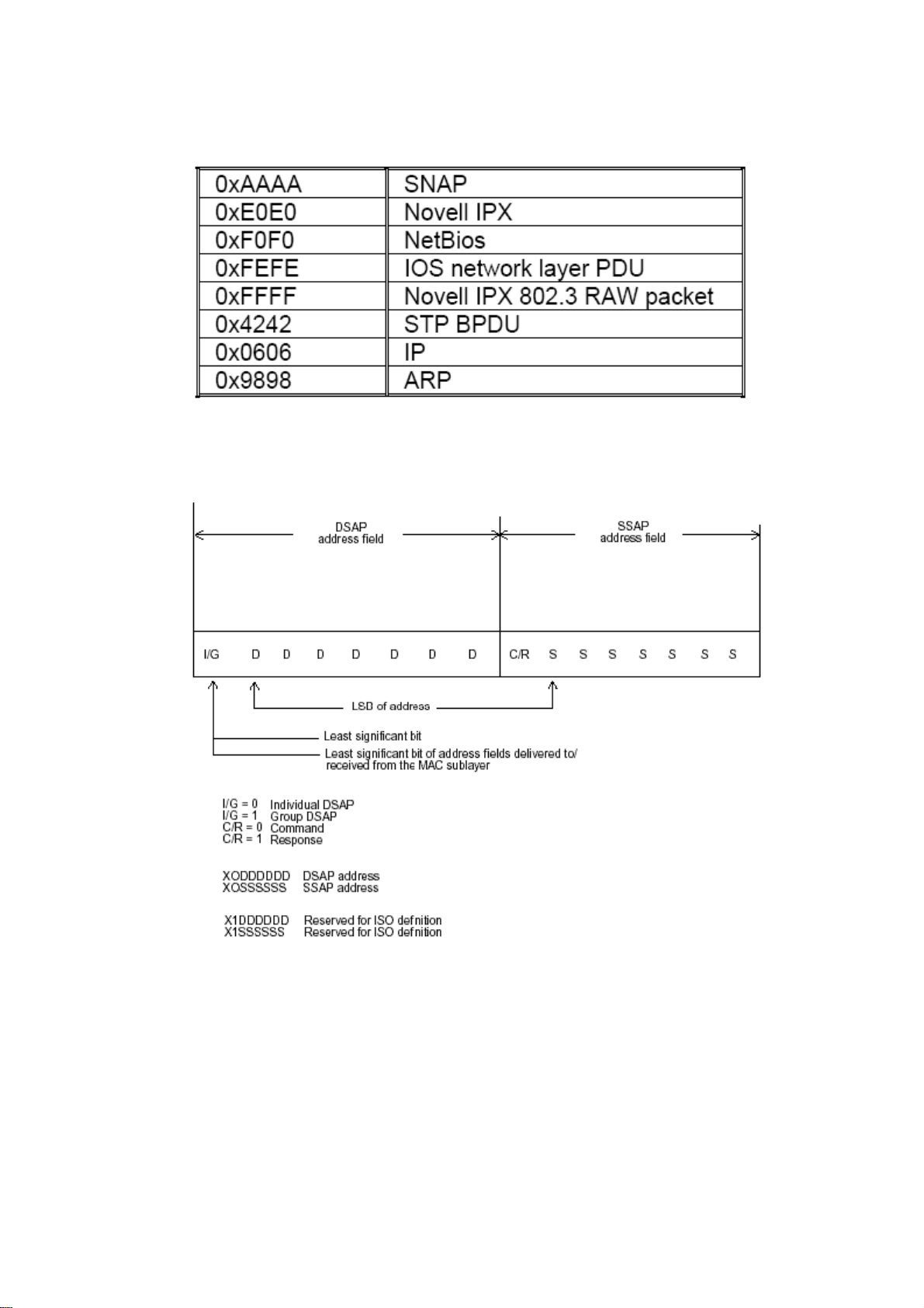
(command or response). The DSAP and SSAP pair with some reserved values indicates
some well-known services listed in the table below.
LLC type 1 connectionless service, LLC type 2 connection-oriented service and LLC type
3 acknowledge connectionless service are three types of LLC frame for all classes of
service. In Fig 3-2, it shows the format of Service Access Point (SAP). Please refer to
IEEE802.2 for more details.
22..22 MMeeddiiaa AAcccceessss CCoonnttrrooll ((MMAACC)
MMAACC AAddddrreessssiinngg
Because LAN is composed of many nodes, for the data exchanged among these nodes,
each node must have its own unique address to identify who should send the data or should
receive the data. In OSI model, each layer provides its own mean to identify the unique
address in some form, for example, IP address in network layer.
VigorSwitch P1100 User’s Guide
17
)
Page 24

The MAC is belonged to Data Link Layer (Layer 2), the address is defined to be a 48-bit
long and locally unique address. Since this type of address is applied only to the Ethernet
LAN media access control (MAC), they are referred to as MAC addresses.
The first three bytes are Organizational Unique Identifier (OUI) code assigned by IEEE.
The last three bytes are the serial number assigned by the vendor of the network device. All
these six bytes are stored in a non-volatile memory in the device. Their format is as the
following table and normally written in the form as aa-bb-cc-dd-ee-ff, a 12 hexadecimal
digits separated by hyphens, in which the aa-bb-cc is the OUI code and the dd-ee-ff is the
serial number assigned by manufacturer.
Bit 47 Bit 0
st
byte 2nd byte 3rd byte 4th byte 5th byte 6th byte
1
OUI code Serial number
The first bit of the first byte in the Destination address (DA) determines the address to be a
Unicast (0) or Multicast frame (1), known as I/G bit indicating individual (0) or group (1).
So the 48-bit address space is divided into two portions, Unicast and Multicast. The second
bit is for global-unique (0) or locally-unique address. The former is assigned by the device
manufacturer, and the later is usually assigned by the administrator. In practice,
global-unique addresses are always applied.
A unicast address is identified with a single network interface. With this nature of MAC
address, a frame transmitted can exactly be received by the target an interface the
destination MAC points to.
A multicast address is identified with a group of network devices or network interfaces. In
Ethernet, a many-to-many connectivity in the LANs is provided. It provides a mean to send
a frame to many network devices at a time. When all bit of DA is 1s, it is a broadcast,
which means all network device except the sender itself can receive the frame and
response.
EEtthheerrnneett FFrraammee FFoorrmmaatt
There are two major forms of Ethernet frame, type encapsulation and length encapsulation,
both of which are categorized as four frame formats 802.3/802.2 SNAP, 802.3/802.2,
Ethernet II and Netware 802.3 RAW. We will introduce the basic Ethernet frame format
defined by the IEEE 802.3 standard required for all MAC implementations. It contains
seven fields explained below.
PRE SFD DA SA Type/Length Data Pad bit if any FCS
7 7 6 6 2 46-1500 4
Preamble (PRE) - The PRE is 7-byte long with alternating pattern of ones and zeros used
to tell the receiving node that a frame is coming, and to synchronize the physical receiver
with the incoming bit stream. The preamble pattern is:
10101010 10101010 10101010 10101010 10101 010 10101010 10101010
Start-of-frame delimiter (SFD) - The SFD is one-byte long with alternating pattern of
ones and zeros, ending with two consecutive 1-bits. It immediately follows the preamble
and uses the last two consecutive 1s bit to indicate that the next bit is the start of the data
packet and the left-most bit in the left-most byte of the destination address. The SFD
pattern is 10101011.
Destination address (DA) - The DA field is used to identify which network device(s)
should receive the packet. It is a unique address. Please see the section of MAC addressing.
18
VigorSwitch P1100 User’s Guide
Page 25

Source addresses (SA) - The SA field indicates the source node. The SA is always an
individual address and the left-most bit in the SA field is always 0.
Length/Type - This field indicates either the number of the data bytes contained in the data
field of the frame, or the Ethernet type of data. If the value of first two bytes is less than or
equal to 1500 in decimal, the number of bytes in the data field is equal to the Length/Type
value, i.e. this field acts as Length indicator at this moment. When this field acts as Length,
the frame has optional fields for 802.3/802.2 SNAP encapsulation, 802.3/802.2
encapsulation and Netware 802.3 RAW encapsulation. Each of them has different fields
following the Length field.
If the Length/Type value is greater than 1500, it means the Length/Type acts as Type.
Different type value means the frames with different protocols running over Ethernet being
sent or received.
For example,
0x0800 IP datagram
0x0806 ARP
0x0835 RARP
0x8137 IPX datagram
0x86DD IPv6
Data - Less than or equal to 1500 bytes and greater or equal to 46 bytes. If data is less than
46 bytes, the MAC will automatically extend the padding bits and have the payload be
equal to 46 bytes. The length of data field must equal the value of the Length field when
the Length/Type acts as Length.
Frame check sequence (FCS) - This field contains a 32-bit cyclic redundancy check
(CRC) value, and is a check sum computed with DA, SA, through the end of the data field
with the following polynomial.
It is created by the sending MAC and recalculated by the receiving MAC to check if the
packet is damaged or not.
HHooww ddooeess aa MMAACC wwoorrkk??
The MAC sub-layer has two primary jobs to do:
1. Receiving and transmitting data. When receiving data, it parses frame to detect error;
when transmitting data, it performs frame assembly.
2. Performing Media access control. It prepares the initiation jobs for a frame
transmission and makes recovery from transmission failure.
FFrraammee ttrraannssmmiissssiioonn
As Ethernet adopted Carrier Sense Multiple Access with Collision Detect (CSMA/CD), it
detects if there is any carrier signal from another network device running over the physical
medium when a frame is ready for transmission. This is referred to as sensing carrier, also
“Listen”. If there is signal on the medium, the MAC defers the traffic to avoid a
transmission collision and waits for a random period of time, called backoff time, then
sends the traffic again.
After the frame is assembled, when transmitting the frame, the preamble (PRE) bytes are
inserted and sent first, then the next, Start of frame Delimiter (SFD), DA, SA and through
VigorSwitch P1100 User’s Guide
19
Page 26

the data field and FCS field in turn. The followings summarize what a MAC does before
transmitting a frame.
1. MAC will assemble the frame. First, the preamble and Start-of-Frame delimiter will be
put in the fields of PRE and SFD, followed DA, SA, tag ID if tagged VLAN is applied,
Ethertype or the value of the data length, and payload data field, and finally put the
FCS data in order into the responded fields.
2. Listen if there is any traffic running over the medium. If yes, wait.
3. If the medium is quiet, and no longer senses any carrier, the MAC waits for a period of
time, i.e. inter-frame gap time to have the MAC ready with enough time and then start
transmitting the frame.
4. During the transmission, MAC keeps monitoring the status of the medium. If no
collision happens until the end of the frame, it transmits successfully. If there is a
collision happened, the MAC will send the patterned jamming bit to guarantee the
collision event propagated to all involved network devices, then wait for a random
period of time, i.e. backoff time. When backoff time expires, the MAC goes back to the
beginning state and attempts to transmit again. After a collision happens, MAC
increases the transmission attempts. If the count of the transmission attempt reaches 16
times, the frame in MAC’s queue will be discarded.
Ethernet MAC transmits frames in half-duplex and full-duplex ways. In halfduplex
operation mode, the MAC can either transmit or receive frame at a moment, but cannot do
both jobs at the same time.
As the transmission of a MAC frame with the half-duplex operation exists only in the same
collision domain, the carrier signal needs to spend time to travel to reach the targeted
device. For two most-distant devices in the same collision domain, when one sends the
frame first, and the second sends the frame, in worstcase, just before the frame from the
first device arrives. The collision happens and will be detected by the second device
immediately. Because of the medium delay, this corrupted signal needs to spend some time
to propagate back to the first device. The maximum time to detect a collision is
approximately twice the signal propagation time between the two most-distant devices.
This maximum time is traded-off by the collision recovery time and the diameter of the
LAN.
In the original 802.3 specification, Ethernet operates in half duplex only. Under this
condition, when in 10Mbps LAN, it’s 2500 meters, in 100Mbps LAN, it’s approximately
200 meters and in 1000Mbps, 200 meters. According to the theory, it should be 20 meters.
But it’s not practical, so the LAN diameter is kept by using to increase the minimum frame
size with a variable-length non-data extension bit field which is removed at the receiving
MAC. The following tables are the frame format suitable for 10M, 100M and 1000M
Ethernet, and some parameter values that shall be applied to all of these three types of
Ethernet.
Actually, the practice Gigabit Ethernet chips do not feature this so far. They all have their
chips supported full-duplex mode only, as well as all network vendors’ devices. So this
criterion should not exist at the present time and in the future. The switch’s Gigabit module
supports only full-duplex mode.
20
VigorSwitch P1100 User’s Guide
Page 27
Parameter
value/LAN
Max. collision
domain DTE to
DTE
Max. collision
domain with
repeater
Slot time
Interframe Gap
AttemptLimit
BackoffLimit
JamSize
MaxFrameSize
MinFrameSize
BurstLimit
10Base 100Base 1000Base
100 meters 100 meters for
UTP
412 meters for
fiber
100 meters for
UTP
316 meters for
fiber
2500 meters 205 meters 200 meters
512 bit times 512 bit times 512 bit times
9.6us 0.96us 0.096us
16 16 16
10 10 10
32 bits 32 bits 32 bits
1518 1518 1518
64 64 64
Not applicable Not applicable 65536 bits
In full-duplex operation mode, both transmitting and receiving frames are processed
simultaneously. This doubles the total bandwidth. Full duplex is much easier than half
duplex because it does not involve media contention, collision, retransmission schedule,
padding bits for short frame. The rest functions follow the specification of IEEE802.3. For
example, it must meet the requirement of minimum inter-frame gap between successive
frames and frame format the same as that in the half-duplex operation.
Because no collision will happen in full-duplex operation, for sure, there is no mechanism
to tell all the involved devices. What will it be if receiving device is busy and a frame is
coming at the same time? Can it use “backpressure” to tell the source device? A function
flow control is introduced in the full-duplex operation.
VigorSwitch P1100 User’s Guide
21
Page 28

22..33 FFllooww CCoonnttrrooll
Flow control is a mechanism to tell the source device stopping sending frame for a
specified period of time designated by target device until the PAUSE time expires. This is
accomplished by sending a PAUSE frame from target device to source device. When the
target is not busy and the PAUSE time is expired, it will send another PAUSE frame with
zero time-to-wait to source device. After the source device receives the PAUSE frame, it
will again transmit frames immediately. PAUSE frame is identical in the form of the MAC
frame with a pause-time value and with a special destination MAC address
01-80-C2-00-00-01. As per the specification, PAUSE operation can not be used to inhibit
the transmission of MAC control frame.
Normally, in 10Mbps and 100Mbps Ethernet, only symmetric flow control is supported.
However, some switches (e.g. 24-Port GbE Web Smart Switch) support not only
symmetric but asymmetric flow controls for the special application. In Gigabit Ethernet,
both symmetric flow control and asymmetric flow control are supported. Asymmetric flow
control only allows transmitting PAUSE frame in one way from one side, the other side is
not but receipt-and-discard the flow control information. Symmetric flow control allows
both two ports to transmit PASUE frames each other simultaneously.
IInntteerr--ffrraammee GGaapp ttiimmee
After the end of a transmission, if a network node is ready to transmit data out and if there
is no carrier signal on the medium at that time, the device will wait for a period of time
known as an inter-frame gap time to have the medium clear and stabilized as well as to
have the jobs ready, such as adjusting buffer counter, updating counter and so on, in the
receiver site. Once the inter-frame gap time expires after the de-assertion of carrier sense,
the MAC transmits data. In IEEE802.3 specification, this is 96-bit time or more.
CCoolllliissiioonn
Collision happens only in half-duplex operation. When two or more network nodes
transmit frames at approximately the same time, a collision always occurs and interferes
with each other. This results the carrier signal distorted and undiscriminated. MAC can
afford detecting, through the physical layer, the distortion of the carrier signal. When a
collision is detected during a frame transmission, the transmission will not stop
immediately but, instead, continues transmitting until the rest bits specified by jamSize are
completely transmitted. This guarantees the duration of collision is enough to have all
involved devices able to detect the collision. This is referred to as Jamming. After jamming
pattern is sent, MAC stops transmitting the rest data queued in the buffer and waits for a
random period of time, known as backoff time with the following formula. When backoff
time expires, the device goes back to the state of attempting to transmit frame. The backoff
time is determined by the formula below. When the times of collision is increased, the
backoff time is getting long until the collision times excess 16. If this happens, the frame
will be discarded and backoff time will also be reset.
22
VigorSwitch P1100 User’s Guide
Page 29

FFrraammee RReecceeppttiioonn
In essence, the frame reception is the same in both operations of half duplex and full
duplex, except that full-duplex operation uses two buffers to transmit and receive the frame
independently. The receiving node always “listens” if there is traffic running over the
medium when it is not receiving a frame. When a frame destined for the target device
comes, the receiver of the target device begins receiving the bit stream, and looks for the
PRE (Preamble) pattern and Start-of-Frame Delimiter (SFD) that indicates the next bit is
the starting point of the MAC frame until all bit of the frame is received.
For a received frame, the MAC will check:
1. If it is less than one slotTime in length, i.e. short packet, and if yes, it will be discarded
by MAC because, by definition, the valid frame must be longer than the slotTime. If
the length of the frame is less than one slotTime, it means there may be a collision
happened somewhere or an interface malfunctioned in the LAN. When detecting the
case, the MAC drops the packet and goes back to the ready state.
2. If the DA of the received frame exactly matches the physical address that the receiving
MAC owns or the multicast address designated to recognize. If not, discards it and the
MAC passes the frame to its client and goes back to the ready state.
3. If the frame is too long. If yes, throws it away and reports frame Too Long.
4. If the FCS of the received frame is valid. If not, for 10M and 100M Ethernet, discards
the frame. For Gigabit Ethernet or higher speed Ethernet, MAC has to check one more
field, i.e. extra bit field, if FCS is invalid. If there is any extra bits existed, which must
meet the specification of IEEE802.3. When both FCS and extra bits are valid, the
received frame will be accepted, otherwise discards the received frame and reports
frameCheckError if no extra bits appended or alignmentError if extra bits appended.
5. If the length/type is valid. If not, discards the packet and reports lengthError.
6. If all five procedures above are ok, then the MAC treats the frame as good and
de-assembles the frame.
WWhhaatt iiff aa VVLLAANN ttaaggggiinngg iiss aapppplliieedd??
VLAN tagging is a 4-byte long data immediately following the MAC source address.
When tagged VLAN is applied, the Ethernet frame structure will have a little change
shown as follows.
Only two fields, VLAN ID and Tag control information are different in comparison with
the basic Ethernet frame. The rest fields are the same.
The first two bytes is VLAN type ID with the value of 0x8100 indicating the received
frame is tagged VLAN and the next two bytes are Tag Control Information (TCI) used to
provide user priority and VLAN ID, which are explained respectively in the following
table.
Bits 15-13
Bit 12
User Priority 7-0, 0 is lowest priority
CFI (Canonical Format Indicator)
1: RIF field is present in the tag header
VigorSwitch P1100 User’s Guide
0: No RIF field is present
23
Page 30

Bits 11-0
VID (VLAN Identifier)
0x000: Null VID. No VID is present and only user priority is
present.
0x001: Default VID
0xFFF: Reserved
Note: RIF is used in Token Ring network to provide source routing and
comprises two fields, Routing Control and Route Descriptor.
When MAC parses the received frame and finds a reserved special value 0x8100 at the
location of the Length/Type field of the normal non-VLAN frame, it will interpret the
received frame as a tagged VLAN frame. If this happens in a switch, the MAC will forward
it, according to its priority and egress rule, to all the ports that is associated with that VID.
If it happens in a network interface card, MAC will deprive of the tag header and process it
in the same way as a basic normal frame. For a VLAN-enabled LAN, all involved devices
must be equipped with VLAN optional function.
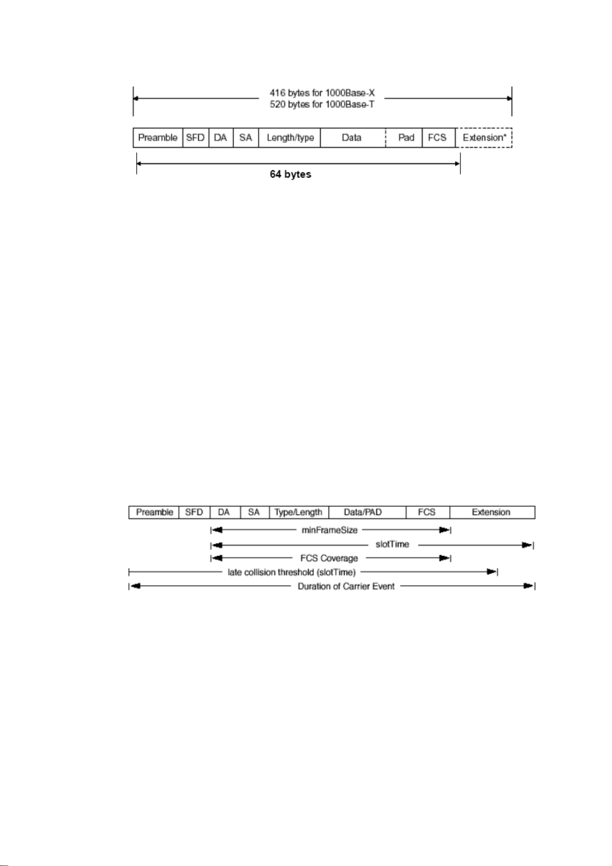
At operating speeds above 100 Mbps, the slotTime employed at slower speeds is
inadequate to accommodate network topologies of the desired physical extent. Carrier
Extension provides a means by which the slotTime can be increased to a sufficient value
for the desired topologies, without increasing the minFrameSize parameter, as this would
have deleterious effects. Nondata bits, referred to as extension bits, are appended to frames
that are less than slotTime bits in length so that the resulting transmission is at least one
slotTime in duration. Carrier Extension can be performed only if the underlying physical
layer is capable of sending and receiving symbols that are readily distinguished from data
symbols, as is the case in most physical layers that use a block encoding/decoding scheme.
The maximum length of the extension is equal to the quantity (slotTime - minFrameSize).
The MAC continues to monitor the medium for collisions while it is transmitting extension
bits, and it will treat any collision that occurs after the threshold (slotTime) as a late
collision.
24
VigorSwitch P1100 User’s Guide
Page 31

Chhaapptteerr 33::
C
Weebb--bbaasseedd
W
This chapter would introduce how to manage your Web Smart Switch and how to
configure the 10/100/1000Mbps TP Ports on the switch via web user interfaces. Web Smart
Switch provides 24 fixed Gigabit Ethernet TP ports. With this facility, you can easily
access and monitor the status like MIBs, port activity, and multicast traffic through any
ports on the switch.
The default values of the Switch are listed in the figure below:
Oppeerraattiioonn ooff
O
Maannaaggee
M
meenntt
m
When the configuration of your Web Smart Switch is finished, you can browse it by the IP
address you set up. For instance, uncheck the Enable box of DHCP Setting first (it is
enabled in default). Next, type http://192.168.1. in the address row in a browser, then the
following screen would show up and ask for your password input for login and access
authentication. The default password is “admin”. For the first time access, please enter the
default password, and click <Apply> button. The login process now would be completed.
Web Smart Switch supports a simplified user management function which allows only one
administrator to configure the switch at one time.
To optimize the display effect, we recommend Microsoft IE and 1024x768 display
resolution.
VigorSwitch P1100 User’s Guide
25
Page 32

33..11 WWeebb MMaannaaggeemmeenntt HHoommee OOvveerrvviieeww
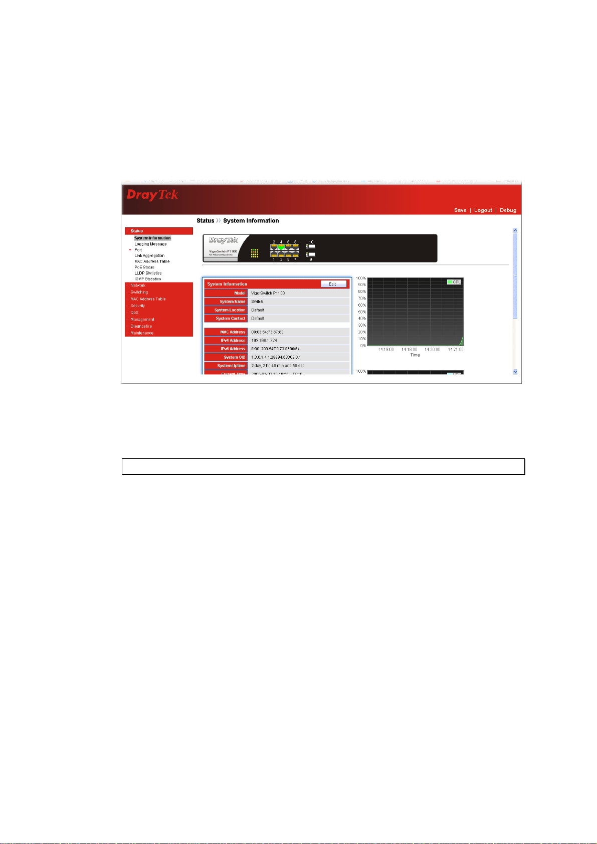
After login, System Information would be displayed as the following illustration. This page
lists default values and shows you the basic information of the switch, including “Model”,
System Name”, “System Location”, “System Contact”, “MAC Address”, “IPv4 Address”,
“IPv6 Address”, “System Uptime”, “Current Time”, “Loader Version”, “Loader Date”,
“Firmware Version”, “Firmware Date”, “ Telnet”, “HTTP”, “HTTPS” and “SNMP”. With
this information, you will know the software version, MAC address, ports available and so
on. It would be helpful while malfunction occurred.
On the top part of the information page, it shows the front panel of the switch. Linked ports
will be displayed in green color, and linked-off ones will be in black. For the optional
modules, the slots with no module will only show covered plates, the other slots with
installed modules would present modules. The images of modules would depend on the
ones you insert. Vice versa, if ports are disconnected, they will show just in black.
On the left side, the main menu tree for web is listed in the page. The functions of each
folder are described in its corresponded section respectively. As to the function names in
normal type are the sub-functions. When clicking it, the function is performed.
26
VigorSwitch P1100 User’s Guide
Page 33

33..22 SSttaattuus
s
33..22..11 SSyysstteemm IInnffoorrmmaattiioonn
Function name:
Status>>System Information
Function description:
System configuration is one of the most important functions. Without a proper setting,
network administrator would not be able to manage the device. The switch supports manual
IP address setting.
Show system description, firmware version, hardware version, MAC address, IP address,
MAC address, active subnet mask, active gateway, and etc.
Parameter description:
System Name
System Location
VigorSwitch P1100 User’s Guide
System name of the switch. This name will also use as
CLI prefix of each line. (“Switch>” or “Switch#”)
Set the location of the switch where it was located.
27
Page 34

System Contact
MAC address
IPv4/IPv6 address
System OID
System Uptime
Current Time
Loader Version
Loader Date
Firmware Version
Firmware Date
33..22..22 LLooggggiinngg MMeessssaaggee
Function name:
System contact of the switch.
For easily managing and maintaining device, you may
write down the contact person and phone here for getting
help soon. You can configure this parameter through the
device’s user interface or SNMP.
It is the Ethernet MAC address of the management agent
in this switch.
The IPv4/IPv6 address of the switch.
Display SNMP system object ID.
Display total elapsed time from booting.
Display current system time of the switch.
Display the boot loader version in this switch.
Display the date of the loader released.
Display the firmware version in this switch.
Display the date of the firmware released.
Status>>Logging Message
Function description:
Display the switch logs.
Parameter description:
Viewing
Severity
Description
Choose RAM or Flash to display related information.
Display the severity of log messages.
Display the related information about the log.
Clear
Refresh
Remove current status.
Refresh current status page.
28
VigorSwitch P1100 User’s Guide
Page 35

33..22..33 PPoorrtt
33..22..33..11 SSttaattiissttiiccss
Function name:
Status>>Port>>Statistics
Function description:
On this page user can get standard counters on network traffic from the interfaces,
Ethernet-like and RMON MIB. Interfaces and Ethernet-like counters display errors on the
traffic passing through each port. RMON counters provide a total count of different frame
types and sizes passing through each port.
Parameter description:
Port
MIB Counter
VigorSwitch P1100 User’s Guide
Select one port to show counter statistics.
Select the MIB counter to show different count type
All: All counters.
Interface: Interface related MIB counters
Etherlike: Ethernet-like related MIB counters
29
Page 36

RMON: RMON related MIB counters
Refresh Rate
33..22..33..22 BBaannddwwiiddtthh UUttiilliizzaattiioonn
Refresh the web page every period of seconds to get new
counter of specified port.
Function name:
Status>>Port>>Bandwidth Utilization
Function description:
Display the Bandwidth Utilization information.
Parameter description:
Refresh Rate
Refresh the web page every period of seconds.
30
VigorSwitch P1100 User’s Guide
Page 37

33..22..44 LLiinnkk AAggggrreeggaattiioonn
Function name:
Status>>Link Aggregation (LAG)
Function description:
Parameter description:
LAG Status
LAG
LAG Name.
Name
Type
Link State
Active Member
Inactive Member
LAG port description.
The type of the LAG.
Static: The groups of ports assigned to a static LAG
are always active members.
LACP: The groups of ports assigned to dynamic
LAG are candidate ports. LACP determines which
candidate ports are active member ports.
LAG port link status.
Active member ports of the LAG.
Inactive or candidate member ports of the LAG.
VigorSwitch P1100 User’s Guide
31
Page 38

33..22..55 MMAACC AAddddrreessss TTaabbllee
Function name:
Status>>MAC Address Table
Function description:
33..22..66 PPooEE SSttaattuuss
Function name:
Status>>PoE Status
Function description:
The PoE Status page displays PoE working mode and PoE consuming power status.
Parameter description:
The type of PoE working mode.
Dynamic(Non Priority Class Mode): Dynamic and
PoE Mode
Total Power(W)
Consuming Power(W)
Allocated Power(W)
Remaining Power(W)
automatic PoE PD priority and power budget
management connection.
Static(Priority Power Base): PoE connection base-on
manual setting by PD priority and power limit.
The system total PoE Power budget.
Consuming total PoE power.
Allocated PoE power budget by system.
Remaining PoE power budget.
32
VigorSwitch P1100 User’s Guide
Page 39

33..22..77 LLLLDDPP SSttaattiissttiiccss
Function name:
Status>>LLDP Statistics
Function description:
The Link Layer Discovery Protocol (LLDP) Statistics page displays summary and per-port
information for LLDP frames transmitted and received on the switch.
Parameter description:
Global Statistics
Insertions
Deletions
Drops
Age Outs
Statistics Table
The number of times the complete set of information
advertised by a particular MAC Service Access Point
(MSAP) has been inserted into tables associated with the
remote systems.
The number of times the complete set of information
advertised by MSAP has been deleted from tables
associated with the remote systems.
The number of times the complete set of information
advertised by MSAP could not be entered into tables
associated with the remote systems because of
insufficient resources.
The number of times the complete set of information
advertised by MSAP has been deleted from tables
associated with the remote systems because the
information timeliness interval has expired.
Port
VigorSwitch P1100 User’s Guide
Interface or port number.
33
Page 40

Transmit Frame Total
Receive Frame Total
Receive Frame Discarded
Receive Frame Errors
Receive TLV Discarded
Receive TLV
Unrecognized
Neighbor Timeout
33..22..88 IIGGMMPP SSttaattiissttiiccss
Function name:
Status>>IGMP Statistics
Number of LLDP frames transmitted on the
corresponding port.
Number of LLDP frames received by this LLDP agent on
the corresponding port, while the LLDP agent is enabled.
Number of LLDP frames discarded for any reason by the
LLDP agent on the corresponding port.
Number of invalid LLDP frames received by the LLDP
agent on the corresponding port, while the LLDP agent is
enabled.
Number of TLVs of LLDP frames discarded for any
reason by the LLDP agent on the corresponding port.
Number of TLVs of LLDP frames that are unrecognized
while the LLDP agent is enabled
Number of age out LLDP frames.
Function description:
IGMP snooping is the process of listening to Internet Group Management Protocol (IGMP)
network traffic. The feature allows a network switch to listen in on the IGMP conversation
between hosts and routers. By listening to these conversations the switch maintains a map
of which links need which IP multicast streams. Multicasts may be filtered from the links
which do not need them and thus controls which ports receive specific multicast traffic.
34
VigorSwitch P1100 User’s Guide
Page 41

Parameter description:
Receive Packet
Total
Valid
Invalid
Other
Leave
Report
General Query
Special Group Query
Special-specific Group
Query
Transmit Packet
Leave
Report
General Query
This field displays the total amount of RX
This field displays the total amount of valid RX.
This field displays the total amount of invalid RX.
This field displays the total amount of other RX.
This field displays the total amount of leave RX.
This field displays the total amount of report RX.
This field displays the total amount of general query
RX.
This field displays the total amount of Special Group
query RX.
This field displays the total amount of Special-specific
Group Query RX.
This field displays the total amount of leave TX.
This field displays the total amount of report TX.
This field displays the total amount of general query
TX.
Special Group Query
Special-specific Group
Query
This field displays the total amount of Special Group
query TX.
This field displays the total amount of Special-specific
Group Query TX.
VigorSwitch P1100 User’s Guide
35
Page 42

33..33 NNeettwwoorrkk
Configure settings for the switch network interface. Offer how the switch connects to a
remote server to get services.
33..33..11 IIPP AAddddrreessss
Function name:
Network>> IP Address
Function description:
Use the IP Setting screen to configure the switch IP address and the default gateway device.
The gateway field specifies the IP address of the gateway (next hop) for outgoing traffic.
The switch needs an IP address for it to be managed over the network. The factory default
IP address is 192.168.1.224. The subnet mask specifies the network number portion of an
IP address. The factory default subnet mask is 255.255.255.0.
Parameter description:
IPv4 Address
36
VigorSwitch P1100 User’s Guide
Page 43

Address Type
IP Address
Subnet Mask
Default Gateway
DNS Server 1
DNS Server 2
IPv6 Address
Auto Configuration
DHCPv6 Client
Select the mode of network connection
Static: Enable static IP address.
Dynamic: Enable Dynamic to type IP address.
Enter the IP address of your switch in dotted decimal
notation for example 192.168.1.224. If static mode is
enabled, enter IP address in this field.
Enter the IP subnet mask of your switch in dotted decimal
notation for example 255.255.255.0. If static mode is
enabled, enter subnet mask in this field.
Enter the IP address of the gateway in dotted decimal
notation. If static mode is enabled, enter gateway address
in this field.
If static mode is enabled, enter primary DNS server
address in this field.
If static mode is enabled, enter secondary DNS server
address in this field.
Select Enable or Disable this function.
DHCPv6 client state.
Enable: Enable DHCPv6 client function.
Disable: Disable DHCPv6 client function.
IPv6 Address
Prefix Length
IPv6 Gateway
DNS Server 1
DNS Server 2
Operational Status
IPv4 Address
IPv4 Default Gateway
IPv6 Address
IPv6 Gateway
Link Local Address
Enter the IPv6 address of your switch. If auto
configuration mode is disabled, enter IPv6 address in this
field.
Specify the prefix for the IPv6 address, when the IPv6
auto configuration and DHCPv6 client are disabled.
Enter the IP address of the gateway in dotted decimal
notation. If auto configuration mode is disabled, enter
IPv6gateway address in this field.
If static mode is enabled, enter primary DNS server
address in this field.
If static mode is enabled, enter secondary DNS server
address in this field.
Display the optional IPv4 address of the switch..
Display the optional IPv4 gateway of the switch.
Display the optional IPv6 address of the switch.
Display the optional IPv6 gateway of the switch.
Display the optional IPv6 link local address for the
switch.
Apply
VigorSwitch P1100 User’s Guide
Save the settings or changes to the switch.
37
Page 44

33..33..22 SSyysstteemm TTiimmee
Function name:
Network>>System Time
Function description:
Parameter description:
Source
Time Zone
SNTP
Address Type
SNTP - Select the radio button to enable using SNTP
server.
From Computer – Select the radio button to specify the
time from PC.
Manual Time – Select the radio button to specify static
time manually.
Select a time zone.
Select Hostname or IPv4.
38
VigorSwitch P1100 User’s Guide
Page 45

Server Address
Server Port
Manual Time
Date
Time
Daylight Saving Time
Type
Offset
Input IP address or hostname of time server.
Input time server port number. Default is 123.
Input the starting date (YYYY-MM-DD).
Input the starting time (HH:MM:SS).
Select the mode of daylight saving time.
None - Disable daylight saving time.
Recurring - Using recurring mode of daylight saving
time.
Non-Recurring - Using non-recurring mode of daylight
saving time.
USA - Using daylight saving time in the United States
that starts on the second Sunday of March and ends on
the first Sunday of November
European - Using daylight saving time in the Europe that
starts on the last Sunday
Specify the adjust offset of daylight saving time.
Recurring
Non-recurring
Operation Status
Current Time
Apply
From - Specify the starting time of recurring daylight
saving time. This field available when selecting
“Recurring” mode.
To - Specify the ending time of recurring daylight saving
time. This field available when selecting “Recurring”
mode.
From - Specify the starting time of non-recurring
daylight saving time. This field available when selecting
“Non-Recurring” mode.
To - Specify the ending time of recurring daylight saving
time. This field available when selecting
“Non-Recurring” mode.
Display current time the router used.
Save the settings or changes to the switch.
VigorSwitch P1100 User’s Guide
39
Page 46

33..44 SSwwiittcchhiinngg
This menu item is used to configure settings for the switch ports, trunk, Layer 2 protocols
and other switch features.
33..44..11 PPoorrtt SSeettttiinngg
Function name:
Switching>>Port Setting
Function description:
It is used to configure switch port settings and show port current status.
Parameter description:
Edit
The following shows the configuration page of port setting.
Check
ports is disabled. A port must be enabled for data
transmission to occur.
Check
setting.
to enable a port. The factory default for all
for one entry and click Edit to modify the
40
VigorSwitch P1100 User’s Guide
Page 47

Parameter description:
Description
Type a brief description for such entry.
State Port admin state.
Enabled: Check the box to enable the port.
Disabled: Uncheck the box to disable the port.
Speed
Port speed capabilities:
Auto: Auto speed with all capabilities.
Auto-10M: Auto speed with 10M ability only.
Auto-100M: Auto speed with 100M ability only.
Auto-1000M: Auto speed with 1000M ability only.
Auto-10/100M: Auto speed with 10/100M ability.
10M: Force speed with 10M ability.
100M: Force speed with 100M ability.
1000M: Force speed with 1000M ability.
Selecting Auto (auto-negotiation) allows one port to
negotiate with a peer port automatically to obtain the
connection speed and duplex mode that both ends
support. When auto-negotiation is turned on, a port on the
switch negotiates with the peer automatically to
determine the connection speed and duplex mode. If the
peer port does not support auto-negotiation or turns off
this feature, the switch determines the connection speed
by detecting the signal on the cable and using half duplex
mode. When the switch’s auto-negotiation is turned off, a
port uses the pre-configured speed and duplex mode
when making a connection, thus requiring you to make
sure that the settings of the peer port are the same in order
to connect.
VigorSwitch P1100 User’s Guide
41
Page 48

Duplex
Flow Control
Port duplex capabilities:
Auto: Auto duplex with all capabilities.
Half: Auto speed with 10/100M ability only.
Full: Auto speed with 10/100/1000M ability only.
A concentration of traffic on a port decreases port
bandwidth and overflows buffer memory causing packet
discards and frame losses. Flow Control is used to
regulate transmission of signals to match the bandwidth
of the receiving port. The switch uses IEEE802.3x flow
control in full duplex mode and backpressure flow
control in half duplex mode. IEEE802.3x flow control is
used in full duplex mode to send a pause signal to the
sending port, causing it to temporarily stop sending
signals when the receiving port memory buffers fill. Back
Pressure flow control is typically used in half duplex
mode to send a "collision" signal to the sending port
(mimicking a state of packet collision) causing the
sending port to temporarily stop sending signals and
resend later.
Select “Auto”/ “Enable” to enable it. Or select
“Disable” to disable it.
42
VigorSwitch P1100 User’s Guide
Page 49

33..44..22 LLiinnkk AAggggrreeggaattiioonn
33..44..22..11 GGrroouupp
Function name:
Switching>>Link Aggregation>>Group
Function description:
Parameter description:
Load Balance Algorithm
Apply
Link Aggregation Table
Edit
The following shows the configuration page of Link Aggregation Group.
Select the LAG load balance distribution algorithm
MAC Address: Based on source and destination
MAC address for all packets
IP/MAC Address: Based on source and destination
IP addresses for IP packet, and source and
destination MAC address for non-IP packets.
Save the settings or changes to the switch.
Check
Check
setting.
to choose a entry.
for one entry and click Edit to modify the
VigorSwitch P1100 User’s Guide
43
Page 50

Parameter description:
LAG
Name
Type
Member
Apply
Close
Display LAG Name.
Type LAG port description.
Select the type of the LAG.
Static: The group of ports assigned to a static LAG
will be always active members.
LACP: The group of ports assigned to dynamic LAG
will be candidate ports. LACP determines which
candidate ports are active member ports.
Available Port - Inactive or candidate member ports of
the LAG.
Selected Port - Active member ports of the LAG.
Save the settings or changes to the switch.
Close the page and return to previous page.
44
VigorSwitch P1100 User’s Guide
Page 51

33..44..22..22 PPoorrtt SSeettttiinngg
Function name:
Switching>>Link Aggregation>>Port Setting
Function description:
Parameter description:
Check
to enable a port. The factory default for all
ports is disabled. A port must be enabled for data
transmission to occur.
Edit
LAG
Type
Description
State
Link Status
Speed
Duplex
Flow Control
Check
for one entry and click Edit to modify the
setting.
LAG Port Name.
LAG Port media type.
LAG port description.
Display LAG port admin state.
Enabled : Enable the port
Disabled : Disable the port
Current LAG port link status.
Up: Port is link up.
Down: Port is link down.
Current LAG port speed configuration and link speed
status.
Current LAG port duplex configuration and link duplex
status.
Current LAG port flow control configuration and link
flow control status.
The following shows the configuration page of port setting.
VigorSwitch P1100 User’s Guide
45
Page 52

Parameter description:
Description
State
Speed
Type a brief description for such entry.
Display LAG port admin state.
Enabled: Check the box to enable the port.
Disabled: Uncheck the box to disable the port.
Port speed capabilities:
Auto: Auto speed with all capabilities.
Auto-10M: Auto speed with 10M ability only.
Auto-100M: Auto speed with 100M ability only.
Auto-1000M: Auto speed with 1000M ability only.
Auto-10/100M: Auto speed with 10/100M ability.
10M: Force speed with 10M ability.
100M: Force speed with 100M ability.
1000M: Force speed with 1000M ability.
Selecting Auto (auto-negotiation) allows one port to
negotiate with a peer port automatically to obtain the
connection speed and duplex mode that both ends
support. When auto-negotiation is turned on, a port on the
switch negotiates with the peer automatically to
determine the connection speed and duplex mode. If the
peer port does not support auto-negotiation or turns off
this feature, the switch determines the connection speed
by detecting the signal on the cable and using half duplex
mode. When the switch’s auto-negotiation is turned off, a
port uses the pre-configured speed and duplex mode
when making a connection, thus requiring you to make
sure that the settings of the peer port are the same in order
to connect.
Flow Control
A concentration of traffic on a port decreases port
bandwidth and overflows buffer memory causing packet
46
VigorSwitch P1100 User’s Guide
Page 53

discards and frame losses. Flow Control is used to
regulate transmission of signals to match the bandwidth
of the receiving port. The switch uses IEEE802.3x flow
control in full duplex mode and backpressure flow
control in half duplex mode. IEEE802.3x flow control is
used in full duplex mode to send a pause signal to the
sending port, causing it to temporarily stop sending
signals when the receiving port memory buffers fill. Back
Pressure flow control is typically used in half duplex
mode to send a "collision" signal to the sending port
(mimicking a state of packet collision) causing the
sending port to temporarily stop sending signals and
resend later.
Select “Auto”/ “Enable” to enable it. Or select
“Disable” to disable it.
Apply
Close
Save the settings or changes to the switch.
Close the page and return to previous page.
VigorSwitch P1100 User’s Guide
47
Page 54

33..44..22..33 LLAACCPP SSeettttiinngg
Function name:
Switching>>Link Aggregation>>LACP Setting
Function description:
It is a Trunk mechanism can aggregate several physical ports to a logical port for higher
bandwidth. The device provides at most 8 groups of trunk configuration. Each trunk group
can aggregate at most 8 ports. For trunk ports traffic balancing, a hash function is applied
and the hash parameters can be configured by user. There are 2 sets of hash algorithm
configurations, each trunk group can bind to a set of configuration. The device also provide
traffic separation mechanism to choose the link maximum id member port dedicated for
known multicast traffic or flooding traffic.
Parameter description:
LACP Setting
System Priority
Configure the system priority of LACP. This decides the
system priority field in LACP PDU.
Apply
Port
Port Priority
Timeout
Save the settings or changes to the switch.
Port Name.
LACP priority value of the port.
The periodic transmissions type of LACP PDUs.
Long: Transmit LACP PDU with slow periodic (30s).
Short: Transmit LACP PDU with fast periodic (1s).
Check
to enable a port. The factory default for all
ports is disabled. A port must be enabled for data
transmission to occur.
Edit
Check
for one entry and click Edit to modify the
setting.
The following shows the configuration page of LACP port setting. Port id could be
physical port id or logical port id (trunk id). Mirror, ingress and egress bandwidth control
48
VigorSwitch P1100 User’s Guide
Page 55

module base on physical port not logic port, however, almost all of the other modules, such
as storm filter, VLAN, L2 table and so on, port id means logical port.
Parameter description:
Port Priority
Timeout
Apply
Close
33..44..33 EEEEEE
Function name:
Switching>>EEE
Function description:
This page allows user to enable or disable port EEE (Energy Efficient Ethernet) function.
Enter the LACP priority value of the port.
Select the periodic transmissions of LACP PDUs. Long:
Transmit LACP PDU with slow periodic (30s). Short:
Transmit LACPP DU with fast periodic (1s).
Save the settings or changes to the switch.
Close the page and return to previous page.
Parameter description:
Port
State
VigorSwitch P1100 User’s Guide
Select one or multiple ports to configure
Port EEE function.
Enabled: Enable EEE function.
49
Page 56

Disabled: Disable EEE function.
Operational Status
Display Port EEE operational status.
Enabled: EEE is operating.
Disabled: EEE is no operating.
Check
to enable a port. The factory default for all
ports is disabled. A port must be enabled for data
transmission to occur.
Edit
Check
for one entry and click Edit to modify the
setting.
The following shows the configuration page of EEE setting.
Parameter description:
Port
State
Select one or multiple ports to configure.
Port EEE admin state.
Enable: Check the box to enable port EEE.
Disable: Uncheck the box to disable port EEE.
Apply
Close
Save the settings or changes to the switch.
Close the page and return to previous page.
50
VigorSwitch P1100 User’s Guide
Page 57

33..44..44 JJuummbboo FFrraammee
Function name:
Switching>>Jumbo Frame
Function description:
This page allows user to configure switch port jumbo frame settings.
Parameter description:
Jumbo Frame
Apply
Check Enable to activate such feature.
Type Jumbo frame size. The valid range is 1526 bytes –
9216 bytes.
Save the settings or changes to the switch.
VigorSwitch P1100 User’s Guide
51
Page 58

33..44..55 PPooEE
33..44..55..11 PPooEE PPoorrtt SSttaattuuss
Function name:
Switching>>PoE>>PoE Port Status
Function description:
This page shows PoE port current status.
Parameter description:
Port
Class
Consuming Power(W)
Max Power(W)
Max Current(mA)
Display the name of the port.
Displays PoE power classification level status.(Dynamic
mode only).
0 : Default (Class 3 : 12.95W)
1 : 0.44W~3.84W (Very Low Power)
2 : 3.84W~6.49W (Low Power)
3 : 6.49W~12.95W (Mid Power)
4 : 12.95W~25.5W (High Power)
Displays current PoE power consumption.
Displays PSE maximum power.
Class 0 : 16.2W
Class 1 : 4.2W
Class 2 : 7.4W
Class 3 : 16.2W
Class 4 : 31.2W
Displays current PoE power current.
52
VigorSwitch P1100 User’s Guide
Page 59

33..44..55..22 PPooEE SSeettttiinngg
Function name:
Switching>>PoE>>PoE Setting
Function description:
This page allows user to configure PoE working type and per port status.
Parameter description:
PoE Mode
Apply
Edit
Port
PD Priority
Static (Priority Power Base) – The PoE Static mode is
manual configure per port on/off, power budget and PD
priority.
Dynamic (NonPriority Class Base) – The PoE Dynamic
mode is automatic negotiation PD device by classification
level of power, and power budget management by port
PD priority. The default device power connection priority
is port1(high priority)>port2>…>port8(low priority).
Click it to enable PoE Mode and activate the PoE
Setting.
Check
to enable a port. The factory default for all
ports is disabled.
Check
for one entry and click Edit to modify the
setting.
Display Port Name.
Display PD Priority.
The following shows the configuration page of PoE setting.
VigorSwitch P1100 User’s Guide
53
Page 60

Parameter description:
Port
State
PD Priority
Power Limit(W)
Apply
Close
Display the port name.
Check
to PoE function.
Select PD Priority.
Low: PD device set to low priority connection.
Medium: PD device set to middle priority connection.
High: PD device set to high priority connection.
Critical: PD device set to highest priority connection.
Selected the power delivery of watts.
15W: PoE port limit set to 15W (802.3af).
30W: PoE port limit set to 30W (802.3at).
Save the settings or changes to the switch.
Close the page and return to previous page.
54
VigorSwitch P1100 User’s Guide
Page 61

33..44..66 VVLLAANN MMaannaaggeemmeenntt
A virtual local area network, virtual LAN or VLAN, is a group of hosts with a common set
of requirements that communicate as if they were attached to the same broadcast domain,
regardless of their physical location. A VLAN has the same attributes as a physical local
area network (LAN), but it allows for end stations to be grouped together even if they are
not located on the same network switch. VLAN membership can be configured through
software instead of physically relocating devices or connections.
33..44..66..11 CCrreeaattee VVLLAANN
Function name:
Switching>>VLAN>>VLAN>>Create VLAN
Function description:
It allows a user to add, edit or delete VLAN settings.
Parameter description:
Apply
Edit
Delete
The following shows the modification page of VLAN name.
Click it to add one VLAN from available VLAN area to
created VLAN area; and activate VLAN table.
Check
Check
Check
VLAN.
to enable the selected VLAN entry.
for one entry and click Edit to modify VLAN.
for one entry and click Delete to remove
VigorSwitch P1100 User’s Guide
55
Page 62

Parameter description:
Name
Apply
Close
33..44..66..22 VVLLAANN CCoonnffiigguurraattiioonn
Function name:
Switching>>VLAN>>VLAN>>VLAN Configuration
Function description:
This page allows a user to configure VLAN Interface related settings.
A PVID (Port VLAN ID) is a tag that adds to incoming untagged frames received on a port
so that the frames are forwarded to the VLAN group that the tag defines.
Type a name for such VLAN profile.
Save the settings or changes to the switch.
Close the page and return to previous page.
Parameter description:
VLAN
Membership
PVID
Select specified VLAN ID to configure Port to VLAN
Settings.
Select the membership for this port with the specified
VLAN ID.
Excluded: Specify the port is excluded in the VLAN.
Forbidden: Specify the port is forbidden in the
VLAN.
Tagged: Specify the port is tagged in the VLAN.
Untagged: Specify the port is untagged in the VLAN.
It will be enabled/disabled according to the membership
56
VigorSwitch P1100 User’s Guide
Page 63

selected.
Apply
33..44..66..33 MMeemmbbeerrsshhiipp
Save the settings or changes to the switch.
Function name:
Switching>>VLAN>>VLAN>>Membership
Function description:
This page shows a table of VLAN Membership setting.
Parameter description:
Port
Mode
Administrative VLAN
Operational VLAN
Edit
Display the interface of this port entry.
Display the interface VLAN mode of this port.
Display the administrative VLAN list of this port.
Display the operational VLAN list of this port.
Click the Edit button to edit the VLAN membership of
this port.
VigorSwitch P1100 User’s Guide
57
Page 64

Select the membership for this port with the specified
VLAN ID.
Excluded: Specify the port is excluded in the VLAN.
Forbidden: Specify the port is forbidden in the
VLAN.
Tagged: Specify the port is tagged in the VLAN.
Untagged: Specify the port is untagged in the VLAN.
PVID-Check this checkbox to select the VLAN ID to be
the port-based VLAN ID for this port.
33..44..66..44 PPoorrtt SSeettttiinngg
Function name:
Switching>>VLAN>>VLAN>>Port Setting
Function description:
This page allow user to configure port VLAN settings such as VLAN port mode, PVID
etc… The attributes depend on different VLAN port mode.
58
VigorSwitch P1100 User’s Guide
Page 65

Parameter description:
Edit
Check
Check
to enable the selected VLAN port entry.
for one entry and click Edit to modify VLAN
port.
Port
Mode
PVID
Accept Frame Type
Ingress Filtering
Display the interface.
Display the VLAN mode of port.
Display the Port-based VLAN ID of port.
Display accepted frame type of port.
Display ingress filter status of port.
The following shows the modification page of VLAN port setting.
Parameter description:
Port
Mode
PVID
Accept Frame Type
Ingress Filtering
Display the interface of the port entry.
Select the VLAN mode of the interface.
Hybrid: Support all functions as defined in IEEE
802.1Qspecification.
Access: Accepts only untagged frames and join an
untagged VLAN.
Trunk: An untagged member of one VLAN at most, and
is a tagged member of zero or more VLANs.
Specify the port-based VLAN ID (1~4094). It’s only
available with hybrid and Trunk mode.
Specify the acceptable-frame-type of the specified
interfaces.
It’s only available with Hybrid mode.
Specify the status of ingress filtering.
It’s only available with Hybrid mode.
VigorSwitch P1100 User’s Guide
59
Page 66

Apply
Close
Save the settings or changes to the switch.
Close the page and return to previous page.
33..44..66..55 VVooiiccee VVLLAANN PPrrooppeerrttyy
Function name:
Switching>>VLAN>>VLAN>>Voice VLAN >>Property
Function description:
This page allow user to configure global and per interface setting of voice VLAN.
Parameter description:
State
VLAN
Cos/802.1p Remarking
Aging Time
Check Enable to enable Voice VLAN.
Select Voice VLAN ID profile
Set checkbox to enable or disable 1p remarking. If
enabled, qualified packets will be remark by this value.
Check Enable to enable such function.
Select a value that will be advertised by LLDP-MED.
Select value of aging time (30~65536 min).
Default is 1440 minutes. A voice VLAN entry will be age
out after this time if without any packet pass through.
60
VigorSwitch P1100 User’s Guide
Page 67

Apply
Edit
Save the settings or changes to the switch.
Check
Check
to enable the selected port setting entry.
for one entry and click Edit to modify port
setting for voice VLAN.
Entry
State
Mode
QoS Policy
Display port entry.
Display enable/disable status of interface.
Display voice VLAN mode.
Display voice VLAN remark will effect which kind of
packet.
The following shows the modification page of voice VLAN port setting.
Parameter description:
State
Mode
QoS Policy
Apply
Close
Set checkbox to enable/disable voice VLAN function of
interface.
Select port voice VLAN mode.
Auto: Voice VLAN auto detect packets that match OUI
table and add received port into voice VLAN ID tagged
member.
Manual: User need add interface to VLAN ID tagged
member manually.
Select port QoS Policy mode.
Voice Packet: QoS attributes are applied to packets with
OUIs in the source MAC address.
All: QoS attributes are applied to packets that are
classified to the Voice VLAN.
Save the settings or changes to the switch.
Close the page and return to previous page.
VigorSwitch P1100 User’s Guide
61
Page 68

33..44..66..66 VVooiiccee VVLLAANN VVooiiccee OOUUII
Function name:
Switching>>VLAN>>VLAN>>Voice VLAN >>Voice OUI
Function description:
This page allow user to add, edit or delete OUI MAC addresses. Default has 8 pre-defined
OUI MAC.
Parameter description:
OUI
Description
Add
Edit
Display OUI address.
Description of the specified MAC address to the voice
VLAN OUI table.
Check
to enable the selected port setting entry.
Click it to create a new voice OUI.
OUI: Input OUI MAC address. It can’t be edited in edit
dialog.
Description: Input description of the specified MAC
address to the voice VLAN OUI table.
Check
for one entry and click Edit to modify OUI
setting for voice VLAN.
Delete
Click it to remove the selected voice VLAN entry.
62
VigorSwitch P1100 User’s Guide
Page 69

33..44..77 MMuullttiiccaasstt
In computer networking, multicast (one-to-many or many-to-many distribution) Is group
communication where information is addressed to a group of destination computers
simultaneously.
33..44..77..11 GGeenneerraall PPrrooppeerrttyy
Function name:
Switching>>Multicast>>General>>Properties
Function description:
Parameter description:
Unknown Multicast
Action
Set the unknown multicast action
Drop: drop the unknown multicast data.
Flood: flood the unknown multicast data.
Forward to Router port: forward the unknown
multicast data to router port.
IPv4
Set the ipv4 multicast forward method.
DMAC-VID: forward method dmac+vid.
DIP-VID: forward method dip+sip.
Apply
33..44..77..22 GGeenneerraall GGrroouupp AAddddrreessss
Function name:
Switching>>Multicast>>General>>Group Address
Function description:
To display Multicast General Group web page. This page allow user to browse all multicast
groups that dynamic learned or statically added.
Save the settings or changes to the switch.
VigorSwitch P1100 User’s Guide
63
Page 70

Parameter description:
Add
Edit
Click it to create a new group address profile for
multicast.
VLAN – Specify one VLAN ID.
Group Address – Type the group IP address.
Member – Display the member ports of group.
Available Port - Inactive or candidate member ports.
Selected Port - Active member ports.
Apply – Save the settings.
Check
Check
to select group address profile.
of a group address profile and click Edit to
modify settings.
Delete
Refresh
33..44..77..33 GGeenneerraall RRoouutteerr PPoorrtt
Click it to remove the selected group address profile.
Click it to renew current page.
Function name:
Switching>>Multicast>>General>>Router Port
Function description:
64
VigorSwitch P1100 User’s Guide
Page 71

Parameter description:
VLAN
Member
Life (Sec)
Refresh
The VLAN ID router entry.
Router Port member.
The expiry time of the router entry.
Click it to renew current page.
33..44..77..44 IIGGMMPP SSnnooooppiinngg PPrrooppeerrttyy
Function name:
Switching>>Multicast>>IGMP Snooping>>Property
Function description:
IGMP snooping is the process of listening to Internet Group Management Protocol (IGMP)
network traffic. The feature allows a network switch to listen in on the IGMP conversation
between hosts and routers. By listening to these conversations the switch maintains a map
of which links need which IP multicast streams. Multicasts may be filtered from the links
which do not need them and thus controls which ports receive specific multicast traffic.
Parameter description:
State
Version
VigorSwitch P1100 User’s Guide
Check Enable to set the enabling status of IGMP
functionality.
Set the IGMP snooping version.
IGMPv2: Only support process
65
IGMP v2 packet.
Page 72

IGMPv3: Support v3 basic and v2.
Report Suppression
Apply
VLAN Setting Table
Check Enable to set the enabling status of IGMP v2
report suppression.
Save the settings or changes to the switch.
VLAN ID
Operation Status
Router Port Auto Learn
Query Robustness
Query Interval
Query Max Response
Interval
Last Member Query
count
The IGMP entry VLAN ID.
The enable status of IGMP VLAN functionality.
Enabled: when IGMP Snooping enable and IGMP
VLAN enable and multicast filtering enable.
Disabled: when IGMP Snooping disable or IGMP
VLAN disable or multicast filtering disable.
Set the enabling status of IGMP router port learning.
Enable: Enable learning router port by query and
PIM, DVRMP.
Disable: Disable learning dynamic router port.
The Robustness Variable allows tuning for the expected
packet loss on a subnet.
The interval of queries send general query.
In Membership Query Messages, it specifies the
maximum allowed time before sending a responding
report in units of 1/10 second.
The count that Query-switch sends Group-Specific
Queries when it receives a Leave Group message for a
group.
Last Member Query
Interval
Immediate leave
The interval that Query-switch sends Group-Specific
Queries when it receives a Leave Group message for a
group.
Leave the group when receive IGMP Leave message.
Enable: Enable Fastleave.
Disable: Disable Fastleave.
Edit
Edit
The following shows the modification page of IGMP Snooping VLAN port setting.
Click Edit to edit the IGMP Snooping Table.
Check
Check
settings.
to select VLAN profile for IGMP.
of a VLAN profile and click Edit to modify
66
VigorSwitch P1100 User’s Guide
Page 73

Parameter description:
State
Router Ports Auto Learn
Immediate leave
Query Robustness
Query Interval
Query Max Response
Interval
Last Member Query
count
Last Member Query
Interval
Operational Status
Check Enable to set the enabling status of IGMP
functionality.
Check Enable to enable learning router port by query
and PIM, DVRMP.
Check Enable to leave the group when receive IGMP
Leave message.
The Robustness Variable allows tuning for the expected
packet loss on a subnet.
The admin query interval.
The admin query max response interval.
The admin last member query count.
The admin last member query interval.
A brief table for the above settings.
Apply
Close
VigorSwitch P1100 User’s Guide
Save the settings or changes to the switch.
Close the page and return to previous page.
67
Page 74

33..44..77..55 IIGGMMPP SSnnooooppiinngg QQuueerriieerr
Function name:
Switching>>Multicast>>IGMP Snooping>>Querier
Function description:
This page allows user to configure querier settings on specific VLAN of IGMP Snooping.
Parameter description:
Edit
Check
Check
to select VLAN profile for querier.
of a VLAN profile and click Edit to modify
settings.
VLAN
State
Operational Status
Version
Querier Address
IGMP Snooping querier entry VLAN ID.
The IGMP Snooping querier Admin State.
The IGMP Snooping querier operational status.
The IGMP Snooping querier operational version.
The operational querier IP address on the VLAN.
The following shows the modification page for VLAN IGMP Snooping querier settings.
Parameter description:
VLAN ID
State
Display the VLAN ID.
Check Enable to set the enabling status of IGMP Querier
Election on the chosen VLAN.
68
VigorSwitch P1100 User’s Guide
Page 75

Version
Set the query version of IGMP Querier Election on the
choseVLANs.
IGMPv2: Querier version 2.
IGMPv3: Querier version 3.
Apply
Close
33..44..77..66 IIGGMMPP SSnnooooppiinngg SSttaattiissttiiccss
Save the settings or changes to the switch.
Close the page and return to previous page.
Function name:
Switching>>Multicast>>IGMP Snooping>>Statistics
Function description:
This page allow user to display IGMP Snooping Statistics and clear IGMP Snooping
statistics.
Parameter description:
Receive Packet
VigorSwitch P1100 User’s Guide
Total - Total RX IGMP packet, include IPv4 multicast
data to CPU.
Valid - The valid IGMP Snooping process packet.
InValid - The invalid IGMP Snooping process packet.
Other - The ICMP protocol is not 2, and is not IPv4
multicast data packet.
Leave - IGMP leave packet.
69
Page 76

Report - IGMP join and report packet.
General Query - IGMP general query packet.
Special Group Query - IGMP special group general
query packet.
Source - IGMP special source and group general query
packet.
Transmit Packet
Leave - IGMP leave packet.
Report - IGMP join and report packet.
General Query - IGMP general query packet includes
querier transmit general query packet.
Special Group Query - IGMP special group query
packet include querier transmit special group query
packet.
Source - IGMP special source and group general
query packet.
70
VigorSwitch P1100 User’s Guide
Page 77

33..44..88 SSppaannnniinngg TTrreeee
The Spanning Tree Protocol (STP) is a network protocol that ensures a loop-free topology
for any bridged Ethernet local area network.
33..44..88..11 PPrrooppeerrttyy
Function name:
Switching>>Spanning Tree>>Properties
Function description:
Configure and display STP property configuration.
Parameter description:
State
Operation Mode
Path Cost Specify the path cost method.
VigorSwitch P1100 User’s Guide
Check Enable to activate the settings in this page.
Set the operating mode of STP:
STP: Enable the Spanning Tree (STP) operation.
RSTP: Enable the Rapid Spanning Tree (RSTP)
operation
Long: Specifies that the default port path costs are within
the range: 1~200,000,000.
Short: Specifies that the default port path costs are within
71
Page 78

the range: 1~65,535.
BPDU Handling
Priority
Hello Time
Max Age
Forward Delay
Specify the BPDU forward method when the STP is
disabled.
Filtering: Filter the BPDU when STP is disabled.
Flooding: Flood the BPDU when STP is disabled.
Specify the bridge priority. The valid range is from 0 to
61440, and the value should be the multiple of 4096. It
ensures the probability that the switch is selected as the
root bridge, and the lower value has the higher priority
for the switch to be selected as the root bridge of the
topology.
Specify the STP hello time in second to broadcast its
hello message to other bridge by Designated Ports. Its
valid range is from 1 to 10 seconds.
Specify the time interval in seconds for a switch to wait
the configuration messages, without attempting to
redefine its own configuration.
Specify the STP forward delay time, which is the amount
of time that a port remains in the Listening and Learning
states before it enters the Forwarding state. Its valid range
is from 4 to 10 seconds.
Tx Hold Count
Operational Status
Bridge Identifier
Designated Root
Identifier
Root Port
Root Path Cost
Topology Change Count
Last Topology Change
Apply
Specify the tx-hold-count used to limit the maximum
numbers of packets transmission per second. The valid
range is from 1 to 10.
Bridge identifier of the switch.
Bridge identifier of the designated root bridge.
Operational root port of the switch.
Operational root path cost.
Numbers of the topology changes.
The last time for the topology change.
Save the settings or changes to the switch.
72
VigorSwitch P1100 User’s Guide
Page 79

33..44..88..22 PPoorrtt SSeettttiinngg
Function name:
Switching>>Spanning Tree>>Port Setting
Function description:
Configure and display STP port settings.
Parameter description:
Edit
Check
Check
to select a profile for querier.
of a profile and click Edit to modify settings.
Protocol Migration Check
Port
State
Path Cost
Priority
Operation Edge
Operational
Point-to-Point
Port Role
Port State
Designated Bridge
Designated Port ID
Restart the Spanning Tree Protocol (STP) migration
process (re-negotiate with its neighborhood) on the
specific interface.
Specify the interface ID or the list of interface IDs.
The operational state on the specified port.
STP path cost on the specified port.
STP priority on the specified port.
The operational edge port on the specified port.
The operational edge point-to-point status on the
specified port.
The current port role on the specified port. The possible
values are: “Disabled”, “Root”, “Designated”,
“Alternative”, and “Backup”.
The current port state on the specified port. The possible
values are:
“Disabled”, “Discarding”, “Learning”, and “Forwarding”.
The bridge ID of the designated bridge.
The designated port ID on the switch.
Designated Cost
The following shows the modification page of port setting for spanning tree.
VigorSwitch P1100 User’s Guide
The path cost of the designated port on the switch.
73
Page 80

Parameter description:
State
Path Cost
Priority
Edge Port
Point-to-Point
Enable/Disable the STP on the specified port
Path cost is the cost of transmitting a frame on to a LAN
through that port. It is recommended to assign this value
according to the speed of the bridge. The slower the
media, the higher the cost. Entering 0 means the switch
will automatically assign a value.
Specify the STP priority on the specified port.
Set the edge port configuration:
Enable: Check the box to force to true state (as link to a
host)
Disable: Uncheck the box to force to false state (as link
to a host).
In the edge mode, the interface would be put into the
Forwarding state immediately upon link up. If the edge
mode is enabled for the interface and there are BPDUs
received on the interface, the loop might be occurred in
the short time before the STP state change.
Specify the Point-to-Point port configuration:
Auto: The state is depended on the duplex setting of the
port.
Enable: Click it to force to true state.
Disable: Click it to force to false state.
74
VigorSwitch P1100 User’s Guide
Page 81

Apply
Close
Save the settings or changes to the switch.
Close the page and return to previous page.
33..44..88..33 SSttaattiissttiiccss
Function name:
Switching>>Spanning Tree>> Statistics
Function description:
To display STP statistics.
Bridge Protocol Data Units (BPDUs) are frames that contain information about the
Spanning tree protocol (STP). Switches send BPDUs using a unique MAC address from its
origin port and a multicast address as destination MAC (01:80:C2:00:00:00, or
01:00:0C:CC:CC:CD for Per VLAN Spanning Tree). For STP algorithms to function, the
switches need to share information about themselves and their connections. What they
share are bridge protocol data units (BPDUs). BPDUs are sent out as multicast frames to
which only other layer 2 switches or bridges are listening. If any loops (multiple possible
paths between switches) are found in the network topology, the switches will co-operate to
disable a port or ports to ensure that there are no loops; that is, from one device to any other
device in the layer 2 network, only one path can be taken.
Parameter description:
Refresh Rate
Port
Receive BPDU(Config)
VigorSwitch P1100 User’s Guide
The option to refresh the statistics automatically.
Check
to select VLAN profile for querier.
It displays the port number.
The counts of the received CONFIG BPDU.
75
Page 82

Receive BPDU(TCN)
Transmit BPDU(Config)
Transmit BPDU(TCN)
Clear
Refresh
View
The counts of the received TCN BPDU.
The counts of the transmitted CONFIG BPDU.
The counts of the transmitted TCN BPDU
Remove the value displayed on this page.
Refresh the page.
Display a pop up window with configurable rate page.
33..55 MMAACC AAddddrreessss TTaabbllee
MAC Address Table is used to show dynamic MAC table and configure settings for static
MAC entries.
33..55..11 DDyynnaammiicc AAddddrreessss
Function name:
MAC Address Table>>Dynamic Address
Function description:
Parameter description:
Aging Time
Apply
Dynamic Address Table
<10-630> The Dynamic MAC address aging out value.
Save the settings or changes to the switch.
Check
to select VLAN profile for querier.
76
VigorSwitch P1100 User’s Guide
Page 83

VLAN
MAC Address
Port
Clear
Refresh
Add Static Address
33..55..22 SSttaattiicc AAddddrreessss
This is the VLAN group to which the MAC address
belongs. Select the VLAN to show or clear dynamic
MAC entries. If not select any port, VLAN and MAC
address, the whole dynamic MAC table will be displayed
or cleared.
This field displays the MAC address that will be
forwarded. Select the MAC address to show or clear
dynamic MAC entries. If not select any port, VLAN and
MAC address, the whole dynamic MAC table will be
displayed or cleared.
This field displays the port where the MAC address will
be forwarded.
Click this button to remove any dynamically learned
MAC address forwarding entries.
Refresh the page.
Click this button to add any port into the static MAC
table.
Function name:
MAC Address Table>>Static Address
Function description:
Parameter description:
This is the VLAN group to which the MAC address
VLAN
belongs. Select the VLAN to show or clear static MAC
entries. If not select any port, VLAN and MAC address,
the whole static MAC table will be displayed or cleared.
This field displays the MAC address that will be
forwarded. Select the MAC address to show or clear
MAC Address
static MAC entries. If not select any port, VLAN and
MAC address, the whole static MAC table will be
displayed or cleared.
Port
Add
VigorSwitch P1100 User’s Guide
This field displays the port number defined for such
VLAN.
Click it to create a new profile.
77
Page 84

Edit
Check
modify the settings.
to select VLAN profile and click this button to
Delete
Check
to select VLAN profile and click this button to
delete the profile.
78
VigorSwitch P1100 User’s Guide
Page 85

33..66 SSeeccuurriittyy
Security pages are used to configure settings for the switch security features.
33..66..11 AAcccceessss CCoonnttrrooll
33..66..11..11 AAcccceessss CCoonnttrrooll MMaannaaggeemmeenntt VVLLAANN
Function name:
Security>>Access Control>>Management VLAN
Function description:
This page allow user to change Management VLAN connection.
Parameter description:
Select management VLAN in option list.
Management VLAN
Apply
Management connection, such as http, https, SNMP etc..,
has the same VLAN of management VLAN are allow
connecting to device. Others will be dropped.
Save the settings or changes to the switch.
33..66..11..22 AAcccceessss CCoonnttrrooll MMaannaaggeemmeenntt SSeerrvviiccee
Function name:
Security>>Access Control>>Management Service
Function description:
Parameter description:
VigorSwitch P1100 User’s Guide
79
Page 86

Telnet is the TCP/IP standard protocol for remote
terminal service. TELNET allows a user at one site to
interact with a remote timesharing system at another site
Telnet
as if the user’s keyboard and display connected directly to
the remote machine.
Check Enable to access telnet service or uncheck not to
access telnet service.
HTTP
HTTPS
SNMP
Apply
33..66..22 PPrrootteecctteedd PPoorrtt
Function name:
Security>>Protected Port
Function description:
This page allows user to configure protected port setting to prevent the selected ports from
communicate with each other.
HTTP is the acronym of HyperText Transfer Protocol.
Check Enable to Enable HTTP service.
HTTPS is the acronym of Hypertext Transfer Protocol
over Secure Socket Layer.
Check Enable to Enable HTTPS service.
Manage switch through SNMP.
Check Enable to Enable SNMP service.
Save the settings or changes to the switch.
Parameter description:
Port List
State
Select the port to be protected.
Configure port protect type:
Unprotected: Unprotected port can communicate with
all ports.
Protected: Prevent protected ports from communicate
with each other.
Check
to select port profile.
80
VigorSwitch P1100 User’s Guide
Page 87

Edit
33..66..33 SSttoorrmm CCoonnttrrooll
Function name:
Security>>Storm Control
Function description:
Check
settings.
of a port profile and click Edit to modify
Parameter description:
Mode
IFG
Apply
Port Setting Table
VigorSwitch P1100 User’s Guide
Select the mode of storm control
Packet/Sec: storm control rate calculates by
packet-based.
Kbits/Sec: storm control rate calculates by
octet-based.
Select the rate calculates w/o preamble & IFG (20 bytes)
Exclude: exclude preamble & IFG (20 bytes) when
count ingress storm control rate.
Include: include preamble & IFG (20 bytes) when
count ingress storm control rate.
Save the settings or changes to the switch.
81
Page 88

Port
State
Broadcast
Check
This field displays the port number.
Display the port setting profile enabled or disabled.
State – Display the storm control function
to select port profile.
enabled/disabled.
Rate(Kbps) - Display the storm control rate for
Broadcast packet.
Unknown Multicast
State – Display the storm control function
enabled/disabled.
Rate(Kbps) - Display the storm control rate for unknown
multicast packet.
Unknown Unicast
State – Display the storm control function
enabled/disabled.
Rate(Kbps) - Display the storm control rate for unknown
unicast packet.
Edit
Check
of a port profile and click Edit to modify
settings.
The following shows the modification page of port setting for storm control.
Parameter description:
Port
State
This field displays the port number of physical port.
Determine the state of setting.
Enable:
Check the box to enable the storm control function for the
selected Port.
Uncheck the box to disable the storm control function for
the selected Port.
82
VigorSwitch P1100 User’s Guide
Page 89

Broadcast
Unknown Multicast
Unknown Unicast
Action
Apply
Specify the storm control rate for Broadcast packet.
Value of storm control rate, Unit: Kbps (Kbits
per-second).
The range is from 0 to 1000000.
Specify the storm control rate for unknown multicast
packet.
Value of storm control rate, Unit: Kbps (Kbits
per-second).
The range is from 0 to 1000000.
Specify the storm control rate for unknown unicast
packet.
Value of storm control rate, Unit: Kbps (Kbits
per-second).
The range is from 0 to 1000000.
Select the state of setting.
Drop: Packets exceed storm control rate will be dropped.
Shutdown: Port exceeds storm control rate will be
shutdown.
Save the settings or changes to the switch.
Close
33..66..44 DDooSS
A Denial of Service (DoS) attack is a hacker attempt to make a device unavailable to its
users. DoS attacks saturate the device with external communication requests, so that it
cannot respond to legitimate traffic. These attacks usually lead to a device CPU overload.
The DoS protection feature is a set of predefined rules that protect the network from
malicious attacks. The DoS Security Suite Setting enables activating the security suite.
33..66..44..11 PPrrooppeerrttyy
Function name:
Security>>DoS>>Property
Function description:
This page allows user to configure DoS setting to enable/disable DoS function for Global
Setting.
Close the page and return to previous page.
VigorSwitch P1100 User’s Guide
83
Page 90

Parameter description:
POD
Land
UDP Blat
Avoids ping of death attack.
Ping packets that length are larger than 65535 bytes.
Enable:
Check the box to enable the item DoS setting; uncheck the
box to disable the item DoS setting.
Drops the packets if the source IP address is equal to the
destination IP address.
Enable:
Check the box to enable the item DoS setting; uncheck the
box to disable the item DoS setting.
Drops the packets if the UDP source port equals to the
UDP destination port.
Enable:
Check the box to enable the item DoS setting; uncheck the
box to disable the item DoS setting.
84
VigorSwitch P1100 User’s Guide
Page 91

TCP Blat
DMAC = SMAC
Null Scan Attack
X-Mas Scan Attack
Drops the packages if the TCP source port is equal to the
TCP destination port.
Enable:
Check the box to enable the item DoS setting; uncheck the
box to disable the item DoS setting.
Drops the packets if the destination MAC address is equal
to the source MAC address.
Enable:
Check the box to enable the item DoS setting; uncheck the
box to disable the item DoS setting.
Drops the packets with NULL scan.
Enable:
Check the box to enable the item DoS setting; uncheck the
box to disable the item DoS setting.
Drops the packets if the sequence number is zero, and the
FIN, URG and PSH bits are set.
Enable:
Check the box to enable the item DoS setting; uncheck the
box to disable the item DoS setting.
TCP SYN-FIN Attack
TCP SYN-RST Attack
ICMP Fragments
TCP-SYN
TCP Fragments
Ping Max Size
Drops the packets with SYN and FIN bits set.
Enable:
Check the box to enable the item DoS setting; uncheck the
box to disable the item DoS setting.
Drops the packets with SYN and RST bits set.
Enable:
Check the box to enable the item DoS setting; uncheck the
box to disable the item DoS setting.
Drops the fragmented ICMP packets.
Enable:
Check the box to enable the item DoS setting; uncheck the
box to disable the item DoS setting.
Drops SYN packets with sport less than 1024.
Enable:
Check the box to enable the item DoS setting; uncheck the
box to disable the item DoS setting.
Drops the TCP fragment packets with offset equals to one.
Determine the IPv4/IPv6 PING packet with the length.
Specify the maximum size of the ICMPv4/ICMPv6 ping
packets. The valid range is from 0 to 65535 bytes, and the
default value is 512 bytes.
Enable
IPv4: Check the box to enable the item DoS
setting for IPv4; uncheck the box to disable the item DoS
setting.
Enable IPv6: Check the box to enable the item DoS
setting for IPv6; uncheck the box to disable the item DoS
VigorSwitch P1100 User’s Guide
85
Page 92

setting.
TCP Min Hdr Size
IPv6 Min Fragment
Smurf Attack
Apply
Checks the minimum TCP header and drops the TCP
packets with the header smaller than the minimum size.
The length range is from 0 to 31 bytes, and default length
is 20 bytes.
Enable:
Check the box to enable the item DoS setting; uncheck the
box to disable the item DoS setting.
Checks the minimum size of IPv6 fragments, and drops
the packets smaller than the minimum size. The valid
range is from 0 to 65535 bytes, and default value is 1240
bytes.
Enable:
Check the box to enable the item DoS setting; uncheck the
box to disable the item DoS setting.
Avoid smurf attack. The length range of the netmask is
from 0 to 323 bytes, and default length is 0 byte.
Enable:
Check the box to enable the item DoS setting; uncheck the
box to disable the item DoS setting.
Save the settings or changes to the switch.
86
VigorSwitch P1100 User’s Guide
Page 93

33..66..44..22 PPoorrtt SSeettttiinngg
Function name:
Security>>DoS>>Port Setting
Function description:
To configure and display the state of DoS protection for interfaces.
Parameter description:
Port
State
Edit
Check
to select port profile.
This field displays the port number.
Display the port setting is enabled or disabled.
Check
of a port profile and click Edit to modify
settings.
VigorSwitch P1100 User’s Guide
87
Page 94

33..77 QQooSS
33..77..11 GGeenneerraall
QoS (Quality of Service) functions to provide different quality of service for various
network applications and requirements and optimize the bandwidth resource distribution so
as to provide a network service experience of a better quality.
33..77..11..11 QQooSS PPrrooppeerrttiieess
Function name:
QoS>>General>>Property
Function description:
It is used to configure settings for both basic and advanced modes.
Parameter description:
State
Trust Mode
Check it to enable such function.
Select the QoS operation mode.
CoS: Traffic is mapped to queues based on the CoS
field in the VLAN tag, or based on the per-port default
CoS value if there is no VLAN tag on the incoming
packet.
DSCP: All IP traffic is mapped to queues based on the
DSCP field in the IP header. If traffic is not IP traffic,
88
VigorSwitch P1100 User’s Guide
Page 95

it is mapped to the lowest priority queue.
CoS-DSCP: All IP traffic is mapped to queues based
on the DSCP field in the IP header. If traffic is not IP
but has VLAN tag, mapped to queues based on the
CoS value in the VLAN tag.
IP Precedence: All IP traffic is mapped to queues
based on the IP Precedence field in the IP header. If
traffic is not IP traffic, it is mapped to the lowest
priority queue.
Apply
Port Setting Table
Edit
Port
CoS
Trust
Remarking (CoS)
Remarking (DSCP)
Remarking (IP
Precedence)
Save the settings or changes to the switch.
Check
Check
to select port profile.
of a port profile and click Edit to modify
settings.
Display the name of the port.
Port default CoS priority value for the selected ports.
Port trust state.
Enable: Traffic will follow trust mode in global setting.
Disable: Traffic will always use best efforts.
Port CoS remarking admin state.
Enable: CoS remarking is enabled.
Disable: CoS remarking is disabled.
Port DSCP remarking admin state.
Enable: DSCP remarking is enabled.
Disable: DSCP remarking is disabled.
Port IP Precedence remarking admin state.
Enable: IP Precedence remarking is enabled.
Disable: IP Precedence remarking is disabled.
VigorSwitch P1100 User’s Guide
89
Page 96

The following shows the modification page of port setting for storm control.
Parameter description:
Port
CoS
Trust Mode
Display the port number.
Set default CoS/802.1p priority value for the selected
ports.
Select the QoS operation mode.
CoS/802.1p: Traffic is mapped to queues based on the
CoS field in the VLAN tag, or based on the per-port
default CoS value if there is no VLAN tag on the
incoming packet.
DSCP: All IP traffic is mapped to queues based on the
DSCP field in the IP header. If traffic is not IP traffic,
it is mapped to the lowest priority queue.
CoS/802.1p-DSCP: All IP traffic is mapped to queues
based on the DSCP field in the IP header. If traffic is
not IP but has VLAN tag, mapped to queues based on
the CoS value in the VLAN tag.
IP Precedence: All IP traffic is mapped to queues
based on the IP Precedence field in the IP header. If
traffic is not IP traffic, it is mapped to the lowest
priority queue.
None: All traffic is mapped to the lowest priority
queue.
Remarking
CoS
DSCP
IP Precedence
Apply
Close
Check Enable to enable CoS remark.
Check Enable to enable DSCP remark.
Check Enable to enable IP Precedence remark.
Save the settings or changes to the switch.
Close the page and return to previous page.
90
VigorSwitch P1100 User’s Guide
Page 97

33..77..11..22 QQuueeuuee SScchheedduulliinngg
Function name:
QoS>>General>>Queue Scheduling
Function description:
Parameter description:
Queue
Strict Priority
WRR
Weight
Apply
Queue ID to configure.
Click it to set queue to strict priority type.
Click it to set queue to Weight round robin type.
If the queue type is WRR, set the queue weight for the
queue.
Save the settings or changes to the switch.
VigorSwitch P1100 User’s Guide
91
Page 98

33..77..11..33 CCooSS MMaappppiinngg
Function name:
QoS>>General>>CoS Mapping
Function description:
Parameter description:
CoS to Queue Mapping
Class of service
Queue
Queue of CoS Mapping
Queue
Class of service
Apply
Class of service value.
Select queue ID for the CoS value.
Queue ID.
Select CoS Value for the Queue ID.
Save the settings or changes to the switch.
92
VigorSwitch P1100 User’s Guide
Page 99

33..77..11..44 DDSSCCPP MMaappppiinngg
Function name:
QoS>>General>>DSCP Mapping
Function description:
To display DSCP Mapping web page.
The DSCP to Queue table determines the egress queues of the incoming IP packets based
on their DSCP values. The original VLAN Priority Tag (VPT) of the packet is unchanged.
Use the Queues to DSCP page to remark DSCP value for egress traffic from each queue.
Parameter description:
DSCP to Queue Mapping
DSCP
Queue
Queue to DSCP Mapping
Queue
DSCP
Apply
VigorSwitch P1100 User’s Guide
Select the DSCP value to mapping to the priority and
drop precedence. The DSCP range is 0 to 63.
Select queue ID for the DSCP value.
Queue ID.
Select DSCP Value for the Queue ID.
Save the settings or changes to the switch.
93
Page 100

33..77..11..55 IIPP PPrreecceeddeennccee MMaappppiinngg
Function name:
QoS>>General>>IP Precedence Mapping
Function description:
To display IP Precedence Mapping web page.
This page allow user to configure IP Precedence to Queue Mapping and Queue to IP
Precedence Mapping.
Parameter description:
IP Precedence to Queue Mapping
IP Precedence
Queue
Queue to IP Precedence Mapping
Queue
IP Precedence
Apply
IP Precedence value.
Select queue ID for the IP Precedence value.
Queue ID.
Select IP Precedence value for the queue ID.
Save the settings or changes to the switch.
94
VigorSwitch P1100 User’s Guide
 Loading...