

Page 1

Page 2

VigorSwitch G1280
24 Ports + 4 Combo UTP/SFP Ports
Web Smart Gigabit Switch
User’s Guide
Version: 1.0
Firmware Version: V2.1.0
(For future update, please visit DrayTek web site)
Date: December 19, 2017
ii
VigorSwitch G1280 User’s Guide
Page 3

Copyrights
© All rights reserved. This publication contains information that is protected by copyright. No part may be
reproduced, transmitted, transcribed, stored in a retrieval system, or translated into any language without
written permission from the copyright holders.
Trademarks
The following trademarks are used in this document:
Microsoft is a registered trademark of Microsoft Corp.
Windows, Windows 95, 98, Me, NT, 2000, XP, Vista, 7, 8, 10 and Explorer are trademarks of Microsoft Corp.
Apple and Mac OS are registered trademarks of Apple Inc.
Other products may be trademarks or registered trademarks of their respective manufacturers.
Caution
Circuit devices are sensitive to static electricity, which can damage their delicate electronics. Dry weather
conditions or walking across a carpeted floor may cause you to acquire a static electrical charge.
To protect your device, always:
Touch the metal chassis of your computer to ground the static electrical charge before you pick up the circuit
device.
Pick up the device by holding it on the left and right edges only.
Warranty
We warrant to the original end user (purchaser) that the device will be free from any defects in workmanship or
materials for a period of one (1) year from the date of purchase from the dealer. Please keep your purchase
receipt in a safe place as it serves as proof of date of purchase. During the warranty period, and upon proof of
purchase, should the product have indications of failure due to faulty workmanship and/or materials, we will, at
our discretion, repair or replace the defective products or components, without charge for either parts or labor,
to whatever extent we deem necessary tore-store the product to proper operating condition. Any replacement
will consist of a new or re-manufactured functionally equivalent product of equal value, and will be offered solely
at our discretion. This warranty will not apply if the product is modified, misused, tampered with, da maged by an
act of God, or subjected to abnormal working conditions. The warranty does not cover the bundled or licensed
software of other vendors. Defects which do not significantly affect the usability of the product will not be
covered by the warranty. We reserve the right to revise the manual and online documentation and to make
changes from time to time in the contents hereof without obligation to notify any person of such revision or
changes.
Be a Registered Owner
Web registration is preferred. You can register your Vigor router via http://www.DrayTek.com.
Firmware & Tools Updates
Due to the continuous evolution of DrayTek technology, all routers will be regularly upgraded. Please consult the
DrayTek web site for more information on newest firmware, tools and documents.
More update, please visit www.draytek.com.
VigorSwitch G1280 User’s Guide
iii
Page 4

TTaabbllee ooff CCoonntteennttss
Part I Introduction..............................................................................................................1
I-1 Introduction ................................................................................................................................... 2
I-1-1 Key Features....................................................................................................................... 2
I-1-2 Specifications ...................................................................................................................... 3
I-1-3 Packing List......................................................................................................................... 4
I-1-4 LED Indicators and Connectors .......................................................................................... 4
I-2 Installation..................................................................................................................................... 6
I-2-1 Typical Applications............................................................................................................. 6
I-2-2 Installing Network Cables.................................................................................................. 10
I-2-3 Configuring the Management Agent of Switch.................................................................. 10
I-2-4 Managing VigorSwitch G1280 through Ethernet Port....................................................... 10
I-2-5 IP Address Assignment.....................................................................................................11
I-3 Accessing Web Page of VigorSwitch.......................................................................................... 14
I-4 Dashboard................................................................................................................................... 15
I-5 Status..........................................................................................................................................16
I-5-1 Port Bandwidth Utilization ................................................................................................. 16
I-5-2 LLDP Statistics.................................................................................................................. 17
Part II Switch LAN............................................................................................................19
II-1 General Setup............................................................................................................................ 20
II-1-1 IP Address........................................................................................................................ 20
II-1-2 IPv6 Address.................................................................................................................... 21
II-1-3 Management VLAN..........................................................................................................22
II-2 Port Setting ................................................................................................................................ 23
II-3 Mirror.......................................................................................................................................... 25
II-4 Link Aggregation........................................................................................................................ 26
II-4-1 LAG Setting...................................................................................................................... 26
II-4-2 LAG Management ............................................................................................................ 27
II-4-3 LAG Port Setting............................................................................................................... 28
II-4-4 LACP Setting.................................................................................................................... 29
II-4-5 LACP Port Setting ............................................................................................................ 30
II-5 VLAN Management.................................................................................................................... 31
II-5-1 Create VLAN .................................................................................................................... 31
II-5-2 Interface Settings.............................................................................................................. 32
II-5-3 Voice VLAN...................................................................................................................... 33
II-5-3-1 Properties.................................................................................33
II-5-3-2 Telephony OUI Setting ..................................................................35
II-5-3-3 Port Setting...............................................................................36
II-6 EEE............................................................................................................................................ 37
II-7 Multicast..................................................................................................................................... 38
iv
VigorSwitch G1280 User’s Guide
Page 5

II-7-1 Properties......................................................................................................................... 38
II-7-2 IGMP Snooping................................................................................................................ 39
II-7-2-1 IGMP Setting..............................................................................39
II-7-2-2 IGMP Querier Setting....................................................................41
II-7-2-3 IGMP Static Group .......................................................................42
II-7-2-4 IGMP Group Table........................................................................43
II-7-2-5 IGMP Router Table.......................................................................44
II-8 Jumbo Frame............................................................................................................................. 45
II-9 STP............................................................................................................................................ 46
II-9-1 Properties......................................................................................................................... 46
II-9-2 Port Setting....................................................................................................................... 47
II-9-3 Bridge Setting................................................................................................................... 48
II-9-4 Port Advanced Setting...................................................................................................... 49
II-9-5 Statistics........................................................................................................................... 50
II-10 MAC Address Table.................................................................................................................. 51
II-10-1 Static MAC Setting ......................................................................................................... 51
II-10-2 Dynamic Address Setting............................................................................................... 52
II-10-3 Dynamic Learned ........................................................................................................... 52
Part III Security.................................................................................................................55
III-1 Storm Control............................................................................................................................ 56
III-1-1 Properties........................................................................................................................ 56
III-1-2 Port Setting...................................................................................................................... 57
III-2 DoS........................................................................................................................................... 58
III-2-1 Properties........................................................................................................................ 58
III-2-2 DoS Port Setting.............................................................................................................. 60
Part IV QoS Configuration...............................................................................................61
IV-1 General..................................................................................................................................... 62
IV-1-1 Properties........................................................................................................................ 62
IV-1-1-1 QoS General Setting ....................................................................62
IV-1-1-2 Trust Ports ...............................................................................63
IV-1-2 Port Settings.................................................................................................................... 64
IV-1-3 Queue Settings ............................................................................................................... 66
IV-1-4 CoS Mapping .................................................................................................................. 67
IV-1-5 DSCP Mapping ............................................................................................................... 68
IV-1-6 IP Precedence Mapping.................................................................................................. 69
IV-2 Bandwid th................................................................................................................................. 70
IV-2-1 Ingress Rate Limit........................................................................................................... 70
IV-2-2 Egress Shaping Rate......................................................................................................71
IV-2-3 Egress Shaping Per Queue............................................................................................ 72
Part V System Maintenance............................................................................................73
V-1 LLDP.......................................................................................................................................... 74
VigorSwitch G1280 User’s Guide
v
Page 6

V-1-1 Properties......................................................................................................................... 74
V-1-2 LLDP Port Setting ............................................................................................................ 75
V-1-3 LLDP Local Device........................................................................................................... 76
V-1-4 LLDP Remote Device....................................................................................................... 77
V-1-5 LLDP Overloading............................................................................................................ 78
V-2 SNMP......................................................................................................................................... 79
VI-2-1 Properties........................................................................................................................ 80
V-2-2 SNMP Community............................................................................................................81
V-2-3 SNMP Trap Host.............................................................................................................. 82
V-3 Access Manager........................................................................................................................ 83
V-4 Time and Date............................................................................................................................ 84
VI-4-1 System Time Zone.......................................................................................................... 84
V-4-2 Time ................................................................................................................................. 85
V-5 Backup Manager........................................................................................................................ 86
V-6 Upgrade Manager...................................................................................................................... 87
V-7 Account Manager....................................................................................................................... 88
V-8 Factory Default...........................................................................................................................89
V-9 Reboot Switch............................................................................................................................ 90
Part VI Diagnostics..........................................................................................................91
VI-1 Cable Diagnostics..................................................................................................................... 92
VI-2 Ping Test................................................................................................................................... 93
VI-3 SysLog...................................................................................................................................... 94
VI-3-1 SysLog Explorer.............................................................................................................. 94
VI-3-2 SysLog Settings.............................................................................................................. 95
VI-3-2-1 SysLog Service ...........................................................................95
VI-3-2-2 Local SysLog..............................................................................96
VI-3-2-3 Remote SysLog...........................................................................97
Appendix: Reference.......................................................................................................99
A-1 What’s the Ethernet................................................................................................................... 99
A-2 Media Acce ss Control (MAC).................................................................................................. 102
A-3 Flow Control............................................................................................................................. 106
Index ...............................................................................................................................109
vi
VigorSwitch G1280 User’s Guide
Page 7

Paarrtt II II
P
nttrr
n
o
o
d
uccttii
d
u
o
o
n
n
VigorSwitch G1280 User’s Guide
1
Page 8

II--11 IInnttrroodduuccttiioonn
24 ports + 4 Combo UTP/SFP ports, Gigabit Ports Web Smart Switch is a standard switch that
meets all IEEE 802.3/u/x/z Gigabit, Fast Ethernet specif ications. The switch has 24
10/100/1000Mbps TP ports. It supports telnet, http, https, SSH and SNMP interface for switch
management. The network administrator can logon the switch to monitor, configure and
control each port’s activity. In addition, the switch implements the QoS (Quality of Service),
VLAN, and Trunking. It is suitable for office application.
Vigor switch supports IEEE 802.3az, Energy-Efficient Ethernet, and provides power saving
feature. It can efficiently save the switch power with auto detect the client idle and cable
length to provide different power.
1000Mbps SFP Fiber port fully complies with all IEEE 802.3z and 1000Base-SX/LX standards.
II--11--11 KKeeyy FFeeaattuurreess
Below shows key features of this device:
QQooSS
The switch offers powerful QoS function. This function supports 802.1p V LAN tag pri ority an d
DSCP on Layer 3 of network framework.
VVLLAANN
Support Port-based VLAN and IEEE802.1Q Tag VLAN. Support 24 active VLANs an d VLA N ID
1~4094.
PPoorrtt TTrruunnkkiinngg
Allows one or more links to be aggregated together to form a Link Aggregation Group by the
static setting.
PPoowweerr SSaavviinngg
2
VigorSwitch G1280 User’s Guide
Page 9

The Power saving using the IEEE 802.3az, Energy-Efficient Ethernet to detect the client idle
and cable length automatically and provides the different power. It could efficient to save
the switch power and reduce the power consumption.
II--11--22 SSppeecciiffiiccaattiioonnss
The VigorSwitch G1280, a standalone off-the-shelf switch, provides the comprehensive
features listed below for users to perform system network administration and efficiently and
securely serve your network.
HHaarrddwwaarree
24 10/100/1000Mbps Auto-negotiation Gigab it Et hernet UTP ports
Jumbo frame support 9KB
4 UTP/SFP Combo Ethernet Ports
Programmable classifier for QoS (Layer 2/Layer 3)
8K MAC address and support VLAN ID(1~4094)
Per-port shaping, policing, and Broadcast Storm Control
Power Saving with IEEE 802.3az, Energy-Efficient Ethernet
Full-duplex flow control (IEEE802.3x) and half-duplex backpressure
Extensive front-panel diagnostic LEDs; Power, System
Hardware reset button for resetting configuration to factory default by pressing over 5
seconds
MMaannaaggeemmeenntt
Supports per port traffic monitoring counters
Supports a snapshot of the system Information when you login
Supports port mirror function
Supports the static trunk function
Supports 802.1Q VLAN
Supports user management and limits three users to login
Maximal packet length can be up to 9600 bytes for jumbo frame application
Supports Broadcasting Suppression to avoid network suspended or crashed
Supports to send the trap event while monitored events happened
Supports default configuration which can be restored to overwrite the current
configuration which is working on via Web UI and Reset button of the switch
Supports on-line plug/unplug SFP modules
Supports Quality of Service (QoS) for real time applications based on the information
taken from Layer 2 to Layer 3
Built-in web-based management and CLI management, providing a more convenient UI
for the user
VigorSwitch G1280 User’s Guide
3
Page 10
II--11--33 PPaacckkiinngg LLiisstt
Before you start installing the switch, verify that the package contains the following:
VigorSwitch G1280
AC Power Cord
Quick Start Guide
Rubber feet
Rack mount kit
Please notify your sales representative immediately if any of the aforementioned items is
missing or damaged.
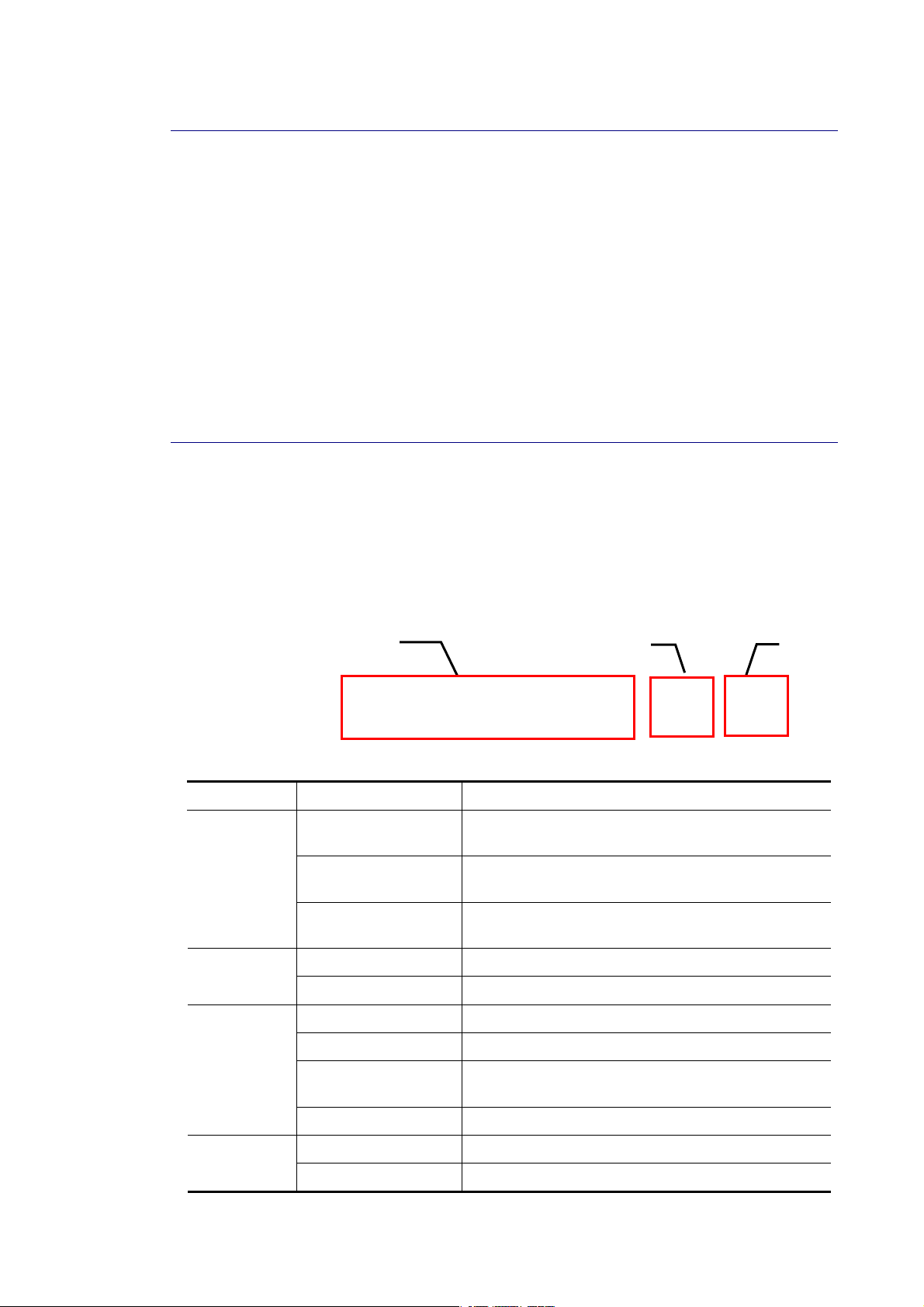
II--11--44 LLEEDD IInnddiiccaattoorrss aanndd CCoonnnneeccttoorrss
Before you use the Vigor device, please get acquainted with the LED indicators and
connectors first. There are 8 Ethernet ports and SFP ports on the front panel of the switch.
LED display area, locating on the front panel, contains an ACT, Power LED and ports working
status of the switch.
LLEEDD EExxppllaannaattiioonn
RJ45 LNK/ACT Port 1 to Port 24
LED Color Explanation
SYS
PWR
RJ 45
LNK/ACT
Port 1 ~ 24
Combo Port
On (Green)
Blinking (Green)
Off
On (Green) The device is powered on and running normally.
Off The device is not ready or is failed.
On (Green) The device is connected with 1000Mbps.
On (Amber) The device is connected with 10/100Mbps.
Blinking The system is sending or receiving data through
The switch finishes system booting and the system
is ready.
The switch is powered on and starts system
booting.
The power is off or the system is not ready /
malfunctioning.
the port.
SFP
LNK/ACT
Off The port is disconnected or the link is failed.
On (Green) The device is connected with 1000Mbps. Combo for
Port 25 ~ 28
4
On (Amber) The device is connected with 10/100Mbps.
VigorSwitch G1280 User’s Guide
Page 11
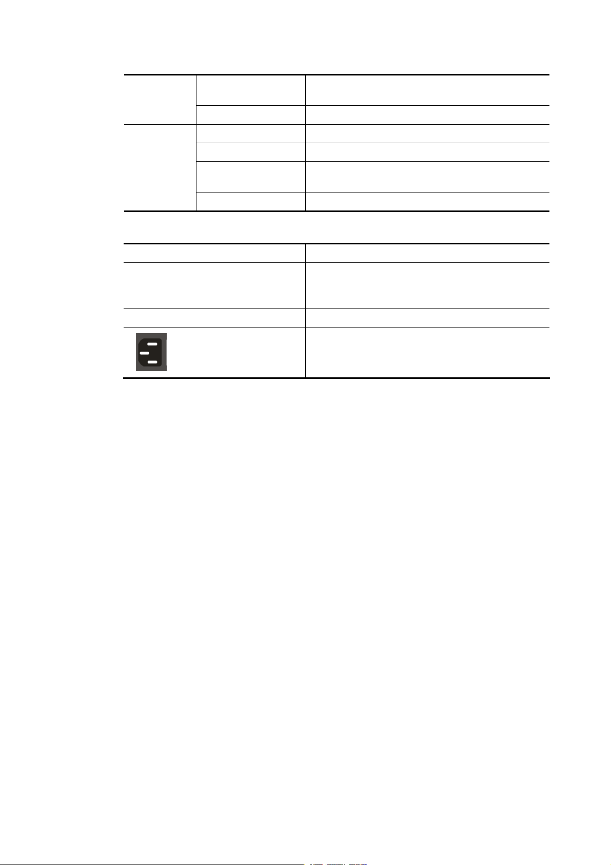
(RJ 45
LNK/ACT)
SFP LNK/ACT
CCoonnnneeccttoorr EExxppllaannaattiioonn
Interface Description
RJ 45 LNK/ACT Port 1 ~ 24 Port 1 to Port 24 can be used for Ethernet
SFP LNK/ACT Port 25 ~ 28
Blinking The system is sending or receiving data through
the port.
Off The port is disconnected or the link is failed.
On (Green) The device is connected with 1000Mbps.
On (Amber) The device is connected with 10/100Mpps.
Blinking The system is sending or receiving data through
the port.
Off The port is disconnected or the link is failed.
connection and PoE connection, depending on the
device connected
Port 25 to Port 28 are used for fiber connection.
Power inlet for AC input (100~240V/AC, 50/60Hz).
.
Power Output -- IEEE 802.3af Max. 15.4W Output Supported;
IEEE 802.3at Max. 30W Output Supported
PoE Power Budget -- 340 Watts (Max)
VigorSwitch G1280 User’s Guide
5
Page 12
II--22 IInnssttaallllaattiioonn
II--22--11 TTyyppiiccaall AApppplliiccaattiioonnss
The VigorSwitch implements 24 Gigabit Ethernet TP ports with auto MDIX and four slots for
the removable module supporting comprehensive fiber types of connection, including LC and
BiDi-LC SFP modules. The switch is suitable for the following applications:
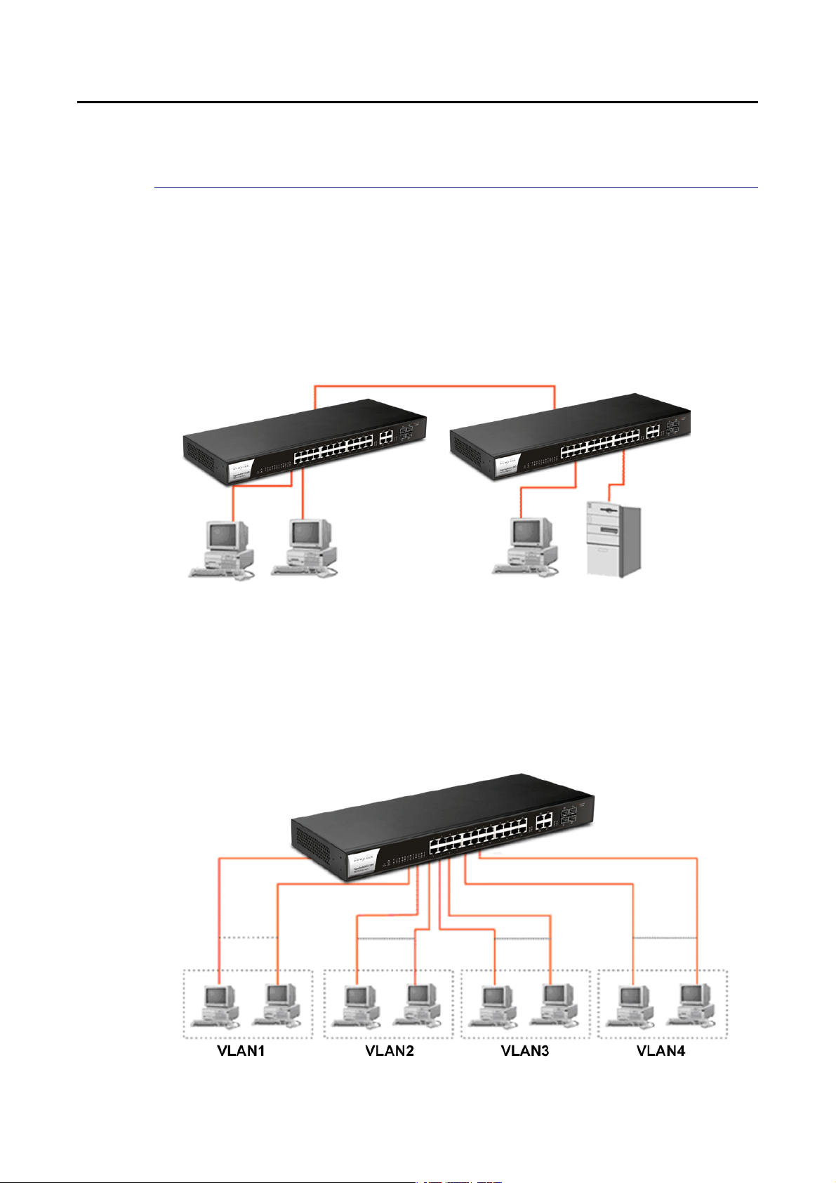
CCaassee 11:: AAllll sswwiittcchh ppoorrttss aarree iinn tthhee ssaammee llooccaall aarreeaa nneettwwoorrkk..
Every port can access each other. (*The switch image is sample only.)
If VLAN is enabled and configured, each node in the network that can communicate each
other directly is bounded in the same VLAN area.
Here VLAN area is defined by what VLAN you are using. The switch supports both port-based
VLAN and tag-based VLAN. They are different in practical deployment, especially in physical
location. The following diagram shows how it works and what the difference they are.
CCaassee 22:: PPoorrtt--bbaasseedd VVLLAANN --11 ((**TThhee sswwiittcchh iimmaaggee iiss ssaammppllee oonnllyy..))
The same VLAN members could not be in different switches.
6
VigorSwitch G1280 User’s Guide
Page 13
Every VLAN members could not access VLAN members ea ch other.
The switch manager has to assign different names for each VLAN groups at one switch.
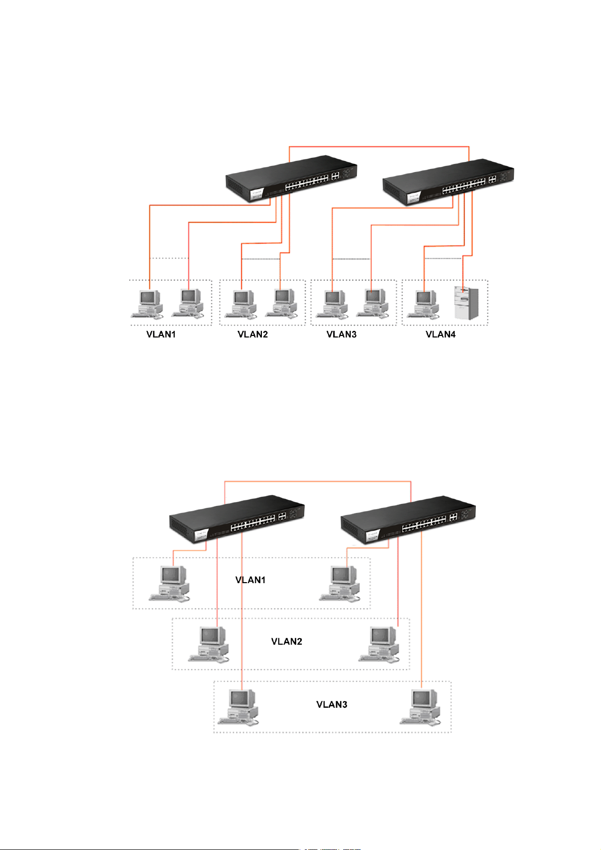
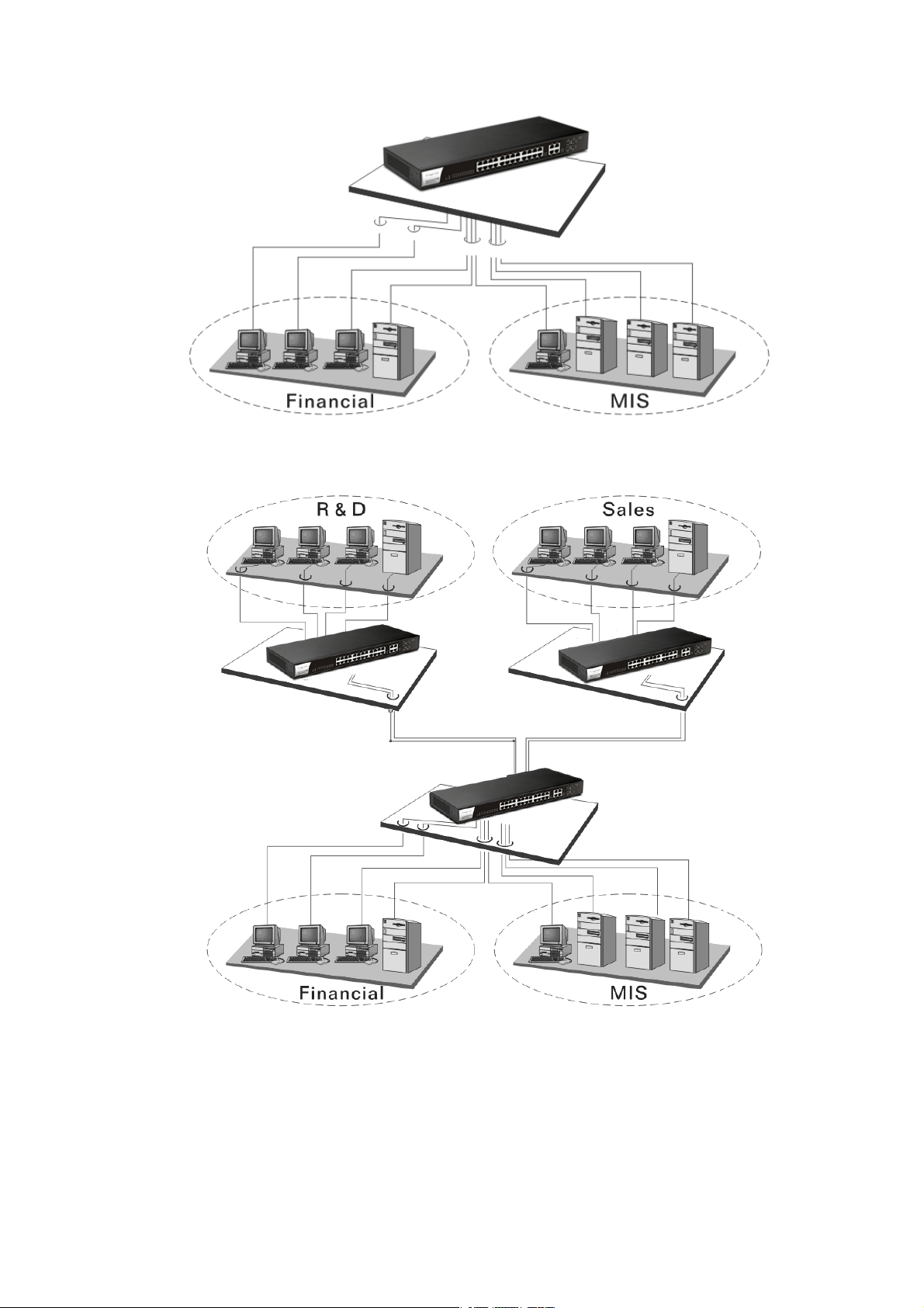
CCaassee 33:: PPoorrtt--bbaasseedd VVLLAANN -- 22
VLAN1 members could not access VLAN 2, VLAN3 and VLAN4 members.
VLAN2 members could not access VLAN1 and VLAN3 members, but they could access
VLAN4 members.
VLAN3 members could not access VLAN 1, VLAN2 and VLAN4.
VLAN4 members could not access VLAN1 and VLAN3 members, but they could access
VLAN2 members.
CCaassee 44:: TThhee ssaammee VVLLAANN mmeemmbbeerrss ccaann bbee aatt ddiiffffeerreenntt sswwiittcchheess wwiitthh tthhee ssaammee VVIIDD
VigorSwitch G1280 User’s Guide
7
Page 14
CCaassee 55:: DDeesskkttoopp IInnssttaallllaattiioonn
1. Install the switch on a level surface that can support the weight of the unit and the
relevant components.
2. Plug the switch with the female end of the provided power cord and plug the male end
to the power outlet.
CCaassee 66:: RRaacckk--mmoouunntt IInnssttaallllaattiioonn
The switch may be standalone, or mounted in a rack. Rack mounting facilitate to an orderly
installation when you are going to install series of networking devices.
Procedures to Rack-mount the switch:
1. Disconnect all the cables from the switch before continuing.
2. Place the unit the right way up on a hard, flat surface with the front facing you.
3. Locate a mounting bracket over the mounting holes on one side of the unit.
4. Insert the screws and fully tighten with a suitable screwdriver.
5. Repeat the two previous steps for the other side of the unit.
6. Insert the unit into the rack and secure with suitable screws.
7. Reconnect all the cables.
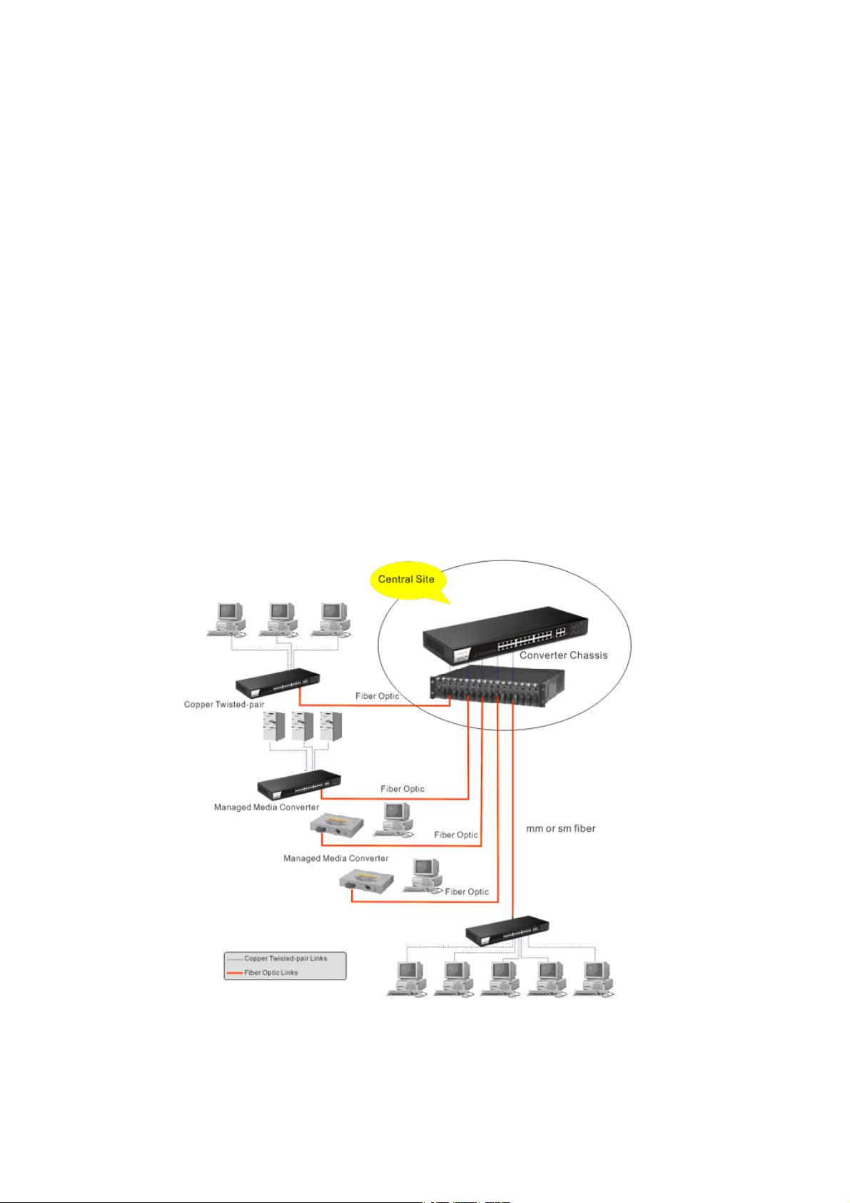
CCaassee 77:: CCeennttrraall SSiittee//RReemmoottee ssiittee aapppplliiccaattiioonn iiss uusseedd iinn ccaarrrriieerr oorr IISSPP
CCaassee 88:: PPeeeerr--ttoo--ppeeeerr aapppplliiccaattiioonn iiss uusseedd iinn ttwwoo rreemmoottee ooffffiicceess
8
VigorSwitch G1280 User’s Guide
Page 15
CCaassee 99:: OOffffiiccee nneettwwoorrkk
VigorSwitch G1280 User’s Guide
9
Page 16

II--22--22 IInnssttaalllliinngg NNeettwwoorrkk CCaabblleess
Crossover or straight-through cable: All the ports on the switch support Auto-MDI/MDI-X
functionality. Both straight-through or crossover cables can be used as the media to connect
the switch with PCs as well as other devices like switches, hubs or router.
Category 3, 4, 5 or 5e, 6 UTP/STP cable: To make a valid connection and obtain the optimal
performance, an appropriate cable that corresponds to different transmitting/receiving
speed is required. To choose a suitable cable, please refer to the following table.
Media Speed Wiring
10 Mbps Category 3,4,5 UTP/STP
10/100/1000
Mbps copper
100Mbps Category 5 UTP/STP
1000 Mbps Category 5e, 6 UTP/STP
II--22--33 CCoonnffiigguurriinngg tthhee MMaannaaggeemmeenntt AAggeenntt ooff SSwwiittcchh
Users can monitor and configure the switch through the following procedures.
Configuring the Management Agent of VigorSwitch G1280 through the Ethernet Port.
There are several ways to configure and monitor the switch through Ethernet port, includes
Web-UI and SNMP.
II--22--44 MMaannaaggiinngg VViiggoorrSSwwiittcchh GG11228800 tthhrroouugghh EEtthheerrnneett PPoorrtt
Before start using the switch, the IP address setting of the switch should be done, then
perform the following steps:
1. Set up a physical path between the configured the switch and a PC by a qualified UTP Cat.
5e cable with RJ-45 connector.
Note: If PC directly connects to the switch, you have to setup the same subnet mask
between them. But, subnet mask may be different for the PC in the remote site. Please
refer to the above figure about the Web Smart Switch default IP address information.
2. After configuring correct IP address on your PC, open your web browser and access
switch's IP address.
Default system account is "admin", with password "admin" in default. Switch IP address is
"192.168.1.224" by default with DHCP client enabled.
10
VigorSwitch G1280 User’s Guide
Page 17
II--22--55 IIPP AAddddrreessss AAssssiiggnnmmeenntt
For IP address configuration, there are three parameters needed to be filled in. They are IP
address, Subnet Mask, Default Gateway and DNS.
IP address:
The address of the network device in the network is used for internetworking communication.
Its address structure looks is shown below. It is “classful” because it is s p lit into predefined
address classes or categories.
Each class has its own network range between the network identifier and host identifier in the
32 bits address. Each IP address comprises two parts: network ide n tifier (address) and host
identifier (address). The former indicates the network where the addressed host resides, and
the latter indicates the individual host in the network which the address of host refers to. And
the host identifier must be unique in the same LAN. Here the term of IP address we used is
version 4, known as IPv4.
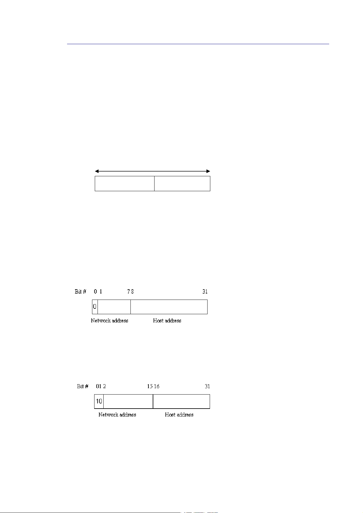
Network identifier Host identifier
32 bits
With the classful addressing, it divides IP address into three classes, class A, class B and class
C. The rest of IP addresses are for multicast and broadcast. The bit length of the network
prefix is the same as that of the subnet mask and is denoted as IP address/X, for example,
192.168.1.0/24. Each class has its address range described below.
Class A:
Address is less than 126.255.255.255. There are a total of 126 networks can be defined
because the address 0.0.0.0 is reserved for default route and 127.0.0.0/8 is reserved for
loopback function.
Class B:
IP address range between 128.0.0.0 and 191.255.255.255. Each cl ass B network has a 16-bit
network prefix followed 16-bit host address. There are 16,384 (2^14)/16 networks able to be
defined with a maximum of 65534 (2^16 –2) hosts per network.
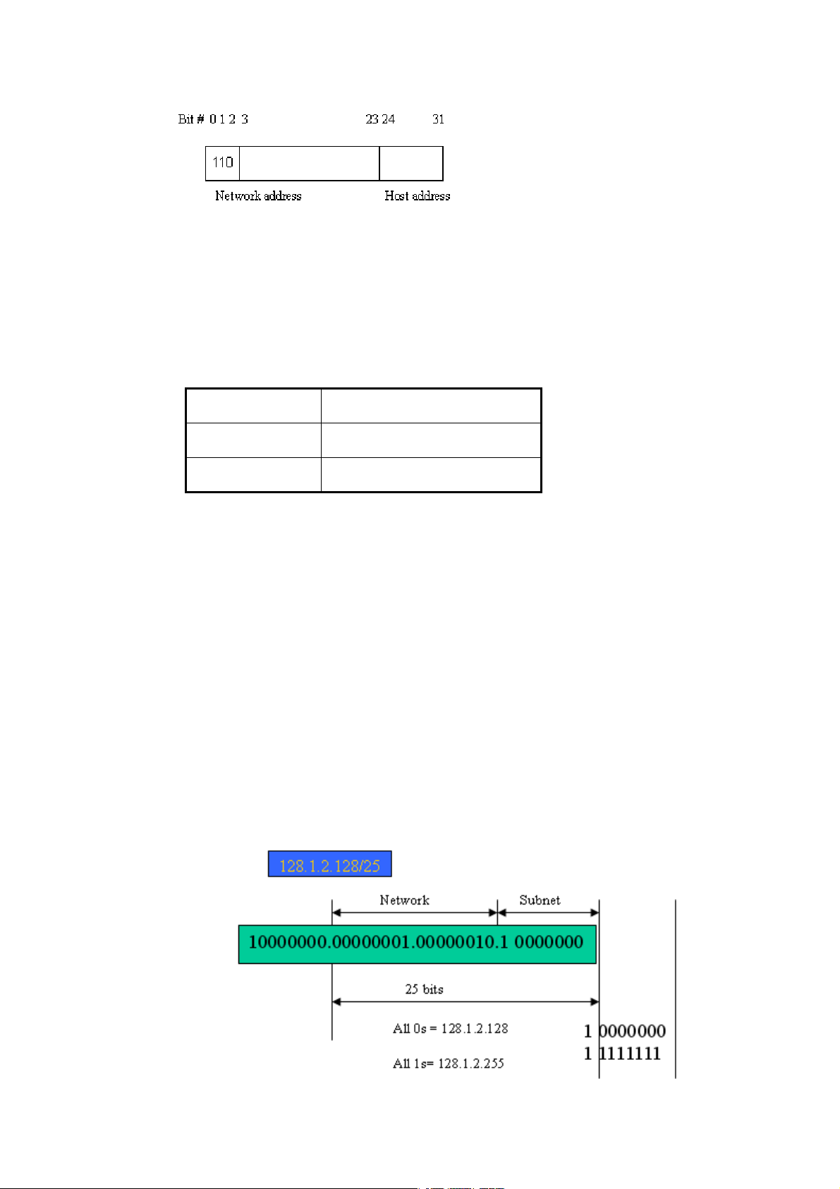
Class C:
IP address range between 192.0.0.0 and 223.255.255.255. Each class C network has a 24-bit
network prefix followed 8-bit host address. There are 2,097,152 (2^ 21)/24 networks able to
be defined with a maximum of 254 (2^8 –2) hosts per network.
VigorSwitch G1280 User’s Guide
11
Page 18
Class D and E:
Class D is a class with first 4 MSB (Most significance bit) set to 1-1-1-0 and is used for IP
Multicast. See also RFC 1112. Class E is a class with first 4 MSB set to 1-1-1-1 and is used for I P
broadcast.
According to IANA (Internet Assigned Numbers Authority), there are three specific IP address
blocks reserved and able to be used for extending internal network. We call it Private IP
address and list below:
Class A 10.0.0.0 --- 10.255.255.255
Class B 172.16.0.0 --- 172.31.255.255
Class C 192.168.0.0 --- 192.168.255.255
Please refer to RFC 1597 and RFC 1466 for more information.
Subnet mask:
It means the sub-division of a class-based network or a CIDR block. The subnet is used to
determine how to split an IP address to the network prefix and the host address in bitwise
basis. It is designed to utilize IP address more efficiently and ease to manage IP network.
For a class B network, 128.1.2.3, it may have a subnet mask 255.255.0.0 in default, in which
the first two bytes is with all 1s. This means more than 60 thousands of nodes in flat IP
address will be at the same network. It’s too large to manage practically. Now if we divide it
into smaller network by extending network prefix from 16 bits to, say 24 bits, that’s using it s
third byte to subnet this class B network. Now it has a subnet mask 255.255.255.0, in which
each bit of the first three bytes is 1. It’s now clear that the first two bytes is used to identify
the class B network, the third byte is used to identify the subnet within this class B network
and, of course, the last byte is the host number.
Not all IP address is available in the sub-netted network. Two special addresses are reserved.
They are the addresses with all zero’s and all one’s host number. For example, an IP address
128.1.2.128, what IP address reserved will be looked like? All 0s mean the network itself, a nd
all 1s mean IP broadcast.
12
VigorSwitch G1280 User’s Guide
Page 19

In this diagram, you can see the subnet mask with 25-bit long, 255.255.255.1 28, contain s 126
members in the sub-netted network. Another is that the length of network prefix equals the
number of the bit with 1s in that subnet mask. With this, you can easily count the number of
IP addresses matched. The following table shows the result.
Prefix Length No. of IP matched No. of Addressable IP
/32 1 /31 2 /30 4 2
/29 8 6
/28 16 14
/27 32 30
/26 64 62
/25 128 126
/24 256 254
/23 512 510
/22 1024 1022
/21 2048 2046
/20 4096 4094
/19 8192 8190
/18 16384 16382
/17 32768 32766
/16 65536 65534
According to the scheme above, a subnet mask 255.255.255.0 will partition a network with
the class C. It means there will have a maximum of 254 effective nodes existed in this
sub-netted network and is considered a physical network in an autonomous network. So it
owns a network IP address which may looks like 168.1.2.0.
With the subnet mask, a bigger network can be cut into small pieces of network. If we want to
have more than two independent networks in a worknet, a partition to the network must be
performed. In this case, subnet mask must be applied.
For different network applications, the subnet mask may look like 255.255.255.240. This
means it is a small network accommodating a maximum of 15 nodes in the network.
For assigning an IP address to the switch, you just have to check what the IP address of the
network will be connected with the switch. Use the same network address and append your
host address to it.
First, IP Address: as shown above, enter “192.168.1.224”, for instance. For sure, an
IP address such as 192.168.1.x must be set on your PC.
Second, Subnet Mask: as shown above, enter “255.255.255.0”. Choose a subnet mask
suitable for your network.
Note: The DHCP Setting is enabled in default. Therefore, if a DHCP server presented on
network connected to the switch, check before accessing your switch is essential.
VigorSwitch G1280 User’s Guide
13
Page 20
4
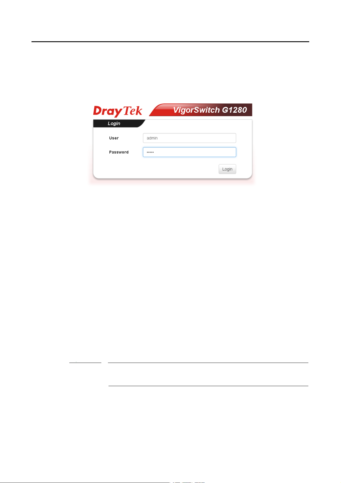
II--33 AAcccceessssiinngg WWeebb PPaaggee ooff VViiggoorrSSwwiittcchh
1. Open any browser (e.g., Firefox) and type “192.168.1.224” as URL.
2. Please type “admin/admin” as the Username/Password and click Login.
3. Now, the Main Screen will appear.
Info
1
The DHCP Setting is enabled in default. Therefore, if a DHCP server presented on
network connected to VigorSwitch, checking before accessing VigorSwitch is
essential.
VigorSwitch G1280 User’s Guide
Page 21
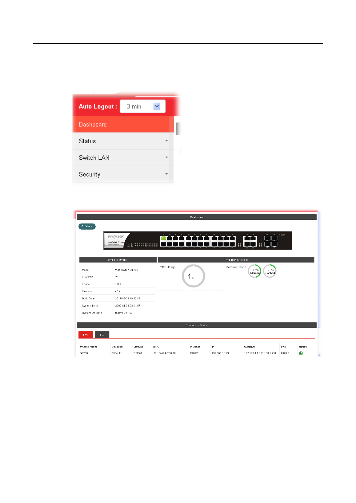
II--44 DDaasshhbbooaarrdd
Click Dashboard from the main menu on the left side of the main page.
A web page with default selections will be displayed on the screen. Refer to the following
figure:
VigorSwitch G1280 User’s Guide
15
Page 22

II--55 SSttaattuuss
II--55--11 PPoorrtt BBaannddwwiiddtthh UUttiilliizzaattiioonn
This page offers the traffic statistics inlcuding data information and data of interframe gap
for each port (GE1 to GE28). In which, data of interframe gap can be displayed or hidden by
choose Enable / Disable for IFG.
16
VigorSwitch G1280 User’s Guide
Page 23

II--55--22 LLLLDDPP SSttaattiissttiiccss
This page offers the statistics of LLDP packets (in, out and error) of each port (GE1 to GE28).
VigorSwitch G1280 User’s Guide
17
Page 24

This page is left blank.
18
VigorSwitch G1280 User’s Guide
Page 25

Paarrtt IIII SS
P
wiittcc
w
h LL
h
A
A
N
N
VigorSwitch G1280 User’s Guide
19
Page 26

IIII--11 GGeenneerraall SSeettuupp
General setup is used to configure settings for the switch network interface and offers how
the switch connects to a remote server to get services.
IIII--11--11 IIPP AAddddrreessss
Use the IP Address screen to configure the switch IP address and the default gateway device.
The gateway field specifies the IP address of the gateway (next hop) for outgoing traffic.
The switch needs an IP address for it to be managed over the network. The factory default IP
address is 192.168.1.224. The subnet mask specifies the network number portion of an IP
address. The factory default subnet mask is 255.255.255.0.
Info
If VigorSwitch has connected to Vigor router, it will use the IP address obtained from
the DHCP server on Vigor router. Thus, the user must type the assigned IP as URL for
accessing into the web user interface of VigorSwitch. If not, 192.168.1.224 shall be
the default IP.
Available settings are explained as follows:
Item Description
Mode Select the mode of network connection.
Static- Use static IPv4 address.
DHCP – Use DHCP provisioned IP address and Gateway if
feasible.
IP Address It is available when Static is selected as Mode.
Enter the IP address of your switch in dotted decimal notation
for example 192.168.1.224. If static mode is enabled, enter IP
address in this field.
Subnet Mask It is available when Static is selected as Mode.
Enter the IP subnet mask of your switch in dotted decimal
20
VigorSwitch G1280 User’s Guide
Page 27

notation for example 255.255.255.0. If static mode is enabled,
enter subnet mask in this field.
Gateway It is available when Static is selected as Mode.
Enter the IP address of the gateway in dotted decimal
notation. If static mode is enabled, enter gateway address in
this field.
DNS Server 1 It is available when Static is selected as Mode.
If static mode is enabled, enter primary DNS server address in
this field.
DNS Server 2 It is available when Static is selected as Mode.
If static mode is enabled, enter secondary DNS server address
in this field.
Apply Save the settings or changes to the switch.
IIII--11--22 IIPPvv66 AAddddrreessss
Use the IPv6 Address screen to configure the switch IPv6 address and the default gateway
device. The gateway field specifies the IPv6 address of the gateway (next hop) for outgoing
traffic.
Available settings are explained as follows:
Item Description
Auto Configuration Enable - Check it to let switch automatically configure IPv6
address.
IPv6 Address It is available when Auto Configuration is Disable.
Enter the IPv6 address of your switch. If auto configuration
mode is disabled, enter IPv6 address in this field.
Link Local Address It is available when Auto Configuration is Disable.
Type
Gateway It is available when Auto Configuration is Disable.
VigorSwitch G1280 User’s Guide
21
Page 28

Enter the IPv6 address of the router as your default IPv6
gateway to access IPv6 Internet or other IPv6 network.
DHCPv6 Client Enable this feature if there is a DHCPv6 server on your network
for assigning IPv6 Address, instead of using Router
Advertisement.
Apply Save the settings or changes to the switch.
IIII--11--33 MMaannaaggeemmeenntt VVLLAANN
This page allows users to change the VLAN ID of management access. Management access
protocols such as http, https, SNMP and etc., are only accessible from the VLAN specified as
management VLAN.
Available settings are explained as follows:
22
Item Description
Management VLAN Select the VLAN ID as management VLAN. You can create
additional VLAN profiles by Switch LAN>>VLAN
management>> Create VLAN.
Apply Save the settings or changes to the switch.
VigorSwitch G1280 User’s Guide
Page 29

IIII--22 PPoorrtt SSeettttiinngg
Port Setting is used to configure settings for the switch ports, trunk, Layer 2 protocols and
other switch features.
Available settings are explained as follows:
Item Description
Ports Use the drop down list to selelct one or more LAN port(s).
Enable State Enable –Click it to enable the port.
Disable – Click it to disable the port.
Speed Port speed capabilities:
Auto: Auto speed with all capabilities.
Auto-10M: Auto speed with 10M ability only.
Auto-100M: Auto speed with 100M ability only.
Auto-1000M: Auto speed with 1000M ability only.
Auto-10/100M: Auto speed with 10/100M ability.
10M: Force speed with 10M ability.
100M: Force speed with 100M ability.
1000M: Force speed with 1000M ability.
Selecting Auto (auto-negotiation) allows one port to negotiate
with a peer port automatically to obtain the connection speed
and duplex mode that both ends support. When
auto-negotiation is turned on, a port on the switch negotiates
with the peer automatically to determine the connection
speed and duplex mode. If the peer port does not support
auto-negotiation or turns off this feature, the switch
determines the connection speed by detecting the signal on
the cable and using half duplex mode. When the switch’s
auto-negotiation is turned off, a port uses the pre-configured
speed and duplex mode when making a connection, thus
requiring you to make sure that the settings of the peer port
are the same in order to connect.
VigorSwitch G1280 User’s Guide
23
Page 30

For SFP fiber module, you might need to manually configure
the speed to match fiber module speed.
Duplex Port duplex capabilities:
Auto: Auto duplex with all capabilities.
Half: Auto speed with 10/100M ability only.
Full: Auto speed with 10/100/1000M ability only.
Flow Control A concentration of traffic on a port decreases port bandwidth
and overflows buffer memory causing packet discards and
frame losses. Flow Control is used to regulate transmission of
signals to match the bandwidth of the receiving port. The
switch uses IEEE802.3x flow control in full duplex mode and
backpressure flow control in half duplex mode. IEEE802.3x
flow control is used in full duplex mode to send a pause signal
to the sending port, causing it to temporarily stop sending
signals when the receiving port memory buffers fill. Back
Pressure flow control is typically used in half duplex mode to
send a "collision" signal to the sending port (mimicking a state
of packet collision) causing the sending port to temporarily
stop sending signals and resend later.
Enable – Click it to enable such function.
Disable – Click it to disable such function.
Apply Save the settings or changes to the switch.
24
VigorSwitch G1280 User’s Guide
Page 31

IIII--33 MMiirrrroorr
This section provides ability to mirror packets coming in or going out on any port to a
destination port. Through the packet duplication in the destination port, this feature is
convinent for system administrator to monitor / understand the traffic operation.
Session ID 1 to 4 can be enabled simultaneously and operate independently.
Available settings are explained as follows:
Item Description
Session ID Select the session ID (profile 1 to 4) of mirror operation you
wish to configure.
Monitor Session State Enable – Enable specified mirror session.
Disable - Disable specified mirror session.
Destination Port Specify the port where you wish to observe the mirrored
packets.
Allow Operation as
Normal Port
Sniff Ports (RX) / (TX) Select the port(s) which you wish to mirror the traffic, Rx for
Apply Save the settings or changes to the switch.
Enable – The destination port is able to function as a port
connecting to network, communicating with other network
devices.
Disable - Only observe the mirrored packets.
mirror the packets into the port, Tx for mirror the packets
going out from the port.
VigorSwitch G1280 User’s Guide
25
Page 32

IIII--44 LLiinnkk AAggggrreeggaattiioonn
LAG means Link Aggregation Group which groups some physical ports together to make a
single high-bandwidth data path. Thus it can implement traffic load sharing among the
member ports in a group to enhance the connection reliability.
IIII--44--11 LLAAGG SSeettttiinngg
This page allows to configure Load Balance Algorithm for Link Aggregation.
Available settings are explained as follows:
Item Description
Load Balance Algorithm Select your Load balance algorithm.
MAC address - Aggregated group will balance the traffic based
on different MAC addresses. Therefore, the packets from
different MAC addresses will be sent to different links.
IP/Mac Address - Aggregated group will balance the traffic
based on MAC addresses and IP addresses. Therefore, the
packets from same MAC addresses but different IP addresses
will be sent to different links.
Apply Save the settings or changes to the switch.
26
VigorSwitch G1280 User’s Guide
Page 33

IIII--44--22 LLAAGG MMaannaaggeemmeenntt
There are eight LAG profiles allowed to group different physical ports (GE1 to GE28). The
system will assign certain port(s) as Active Member and Standby Member according to the GE
selections.
Available settings are explained as follows:
Item Description
Description Display the port description.
Port Type Display the type of the LAG.
Link Status Display LAG port link status.
Active Member Display active memb er ports of the LAG.
Standby Member Display inactive or candidate member ports of the LAG.
Modify It is used to edit the name, type and port number for each link
aggregation profile.
Name- Enter a string as LAG name.
Type – Use the drop down menu to specify the type for LAG.
Static- The static aggregated port sends packets over
active member without detecting or negotiating with
remote aggregated port.
LACP- The LACP aggregated ports place member into
active only after negotiated with remote aggregated port
for best reliability.
VigorSwitch G1280 User’s Guide
27
Page 34

IIII--44--33 LLAAGG PPoorrtt SSeettttiinngg
This page defines port setting for each LAG profile (LAG1 to LAG8), including data speed and
enabling/disabling the flow control.
Available settings are explained as follows:
Item Description
LAG Use the drop down list to selelct one or more LAG profiles.
Enable Enable –Click it to enable the profile.
Disable – Click it to disable the profile.
Speed Port speed capabilities:
Auto: Auto speed with all capabilities.
Auto-10M: Auto speed with 10M ability only.
Auto-100M: Auto speed with 100M ability only.
Auto-1000M: Auto speed with 1000M ability only.
Auto-10/100M: Auto speed with 10/100M ability.
10M: Force speed with 10M ability.
100M: Force speed with 100M ability.
1000M: Force speed with 1000M ability.
Selecting Auto (auto-negotiation) allows one port to negotiate
with a peer port automatically to obtain the connection speed
and duplex mode that both ends support. When
auto-negotiation is turned on, a port on the switch negotiates
with the peer automatically to determine the connection
speed and duplex mode. If the peer port does not support
auto-negotiation or turns off this feature, the switch
determines the connection speed by detecting the signal on
the cable and using half duplex mode. When the switch’s
auto-negotiation is turned off, a port uses the pre-configured
speed and duplex mode when making a connection, thus
requiring you to make sure that the settings of the peer port
are the same in order to connect.
For SFP fiber module, you might need to manually configure
the speed to match fiber module speed.
28
VigorSwitch G1280 User’s Guide
Page 35

9
Flow Control A concentration of traffic on a port decreases port bandwidth
and overflows buffer memory causing packet discards and
frame losses. Flow Control is used to regulate transmission of
signals to match the bandwidth of the receiving port. The
switch uses IEEE802.3x flow control in full duplex mode and
backpressure flow control in half duplex mode. IEEE802.3x
flow control is used in full duplex mode to send a pause signal
to the sending port, causing it to temporarily stop sending
signals when the receiving port memory buffers fill. Back
Pressure flow control is typically used in half duplex mode to
send a "collision" signal to the sending port (mimicking a state
of packet collision) causing the sending port to temporarily
stop sending signals and resend later.
Enable – Click it to enable such function.
Disable – Click it to disable such function.
Apply Save the settings or changes to the switch.
IIII--44--44 LLAACCPP SSeettttiinngg
This page is used to enable or disable the LACP function.
Available settings are explained as follows:
Item Description
LACP Enable – Click it to enable such function.
Disable – Click it to disable the function.
System Priority The priority is used to determine which switch (local or
remote) on the LAG connection is able to decide LACP
activities. The lower the number is, the higher the priority for
Vigorwitch will be. Therefore, the switch with the highest
system priority (e.g., 1) can make decisions about which ports
actively participate in LAG at a given time.
Apply Save the settings or changes to the switch.
VigorSwitch G1280 User’s Guide
2
Page 36

0
IIII--44--55 LLAACCPP PPoorrtt SSeettttiinngg
This section provides few detailed configuration regarding to Ports under LACP protocol.
Available settings are explained as follows:
Item Description
Ports Use the drop down list to specify LAN Port.
Priority Enter a port priority number for the port.
Timeout The timeout option decides how local switch of LAG
connection determines connection to be lost. Switch would
also notify the remote switch about this setting value, so that
remote switch can send LACP PDU in correct timing.
Long - LACP PDU will be sent every 30 seconds. If port member
is not seen over 90 seconds, it will cause port member
timeout.
Short - LACP PDU will be sent per second. If port member is
not seen over 3 seconds, it will cause port member timeout.
Apply Save the settings or changes to the switch.
3
VigorSwitch G1280 User’s Guide
Page 37

IIII--55 VVLLAANN MMaannaaggeemmeenntt
A virtual local area network, virtual LAN or VLAN, is a group of hosts with a common set of
requirements that communicate as if they were attached to the same broadcast domain,
regardless of their physical location. A VLAN has the same attributes as a physical local area
network (LAN), but it allows for end stations to be grouped together even if they are not
located on the same network switch. VLAN membership can be configured through software
instead of physically relocating devices or connections.
IIII--55--11 CCrreeaattee VVLLAANN
This page allows a user to add, edit or delete VLAN settings.
Available settings are explained as follows:
Item Description
Add / Del Select which action to perform, add VLANs or delete VLANs.
Add – Create a new VLAN profile.
Delete – Delete an existed VLAN profile.
VLAN ID Enter the number as VLAN ID to be created or deleted. If you
want to create / delete multiple VLAN profiles, simply enter
multiple VLAN ID separated by comma, and/or range of VLAN
ID using hyphen.
VLAN Name Enter the prefix you wish to add followed by VLAN ID as VLAN
name. Leave it empty for using default "VLAN".
After clicking Apply, you will see:
Apply Save the settings or changes to the switch.
VigorSwitch G1280 User’s Guide
31
Page 38

Modify
- Modify the name of the selected VLAN ID.
New Name - Type a name for such VLAN profile.
OK - Save the settings or changes to the switch.
Cancel - Close the page and return to previous page.
- Delete the selected VALN ID.
IIII--55--22 IInntteerrffaaccee SSeettttiinnggss
This page allows a user to configure interface setting related to VLAN.
Available settings are explained as follows:
Item Description
Port Select Select LAN ports to configure VLAN Settings.
Interface VLAN Mode Select the VLAN mode of the interface.
Hybrid – Support all functions as defined in IEEE
802.1Qspecification.
Access – Accepts only untagged frames and join an untagged
VLAN.
Trunk - An untagged member of one VLAN at most, and is a
tagged member of zero or more VLANs.
PVID A PVID (Port VLAN ID) is a tag that adds to incoming untagged
frames received on a port so that the frames are forwarded to
32
VigorSwitch G1280 User’s Guide
Page 39

the VLAN group that the tag defines.
For port under Access Mode, VLAN ID provided as PVID would
automatically be selected as the untagged VLAN.
Accepted Type Specify the acceptable-frame-type of the specified interfaces.
It’s only available with Hybrid mode.
All - Accept frames regardless it's tagged with 802.1q or not.
Tag Only - Accept frames only with 802.1q tagged.
Untag Only - Accept frames untagged.
Ingress Filtering Enable the ingress filtering to filter out any packets not belong
to any VLAN members of this port. It is enabled automatically
while operating in Access and Trunk mode.
Enabled – Click it to enable the function.
Disabled - Click it to disable the function.
Tagged VLAN Specify the VLAN profile tagged in the VLAN.
Untagged VLAN Specify the VLAN profile untagged in the VLAN.
Forbidden VLAN Specify the VLAN profile forbidden in the VLAN.
Apply Save the settings or changes to the switch.
IIII--55--33 VVooiiccee VVLLAANN
With such feature, a VLAN will be created temporarily and when the specified OUI device
delivers protocol packets related to “VoIP”, VigorSwitch will guide these packets into the
specified Voice LAN with specified priorioty tag to speed up the packet transmission. Such
voice VLAN is only active inside VigorSwitch for packet transmission. After these packets
leave VigorSwitch, the Voice VLAN tag will be removed immediately.
IIII--55--33--11 PPrrooppeerrttiieess
This page allows a user to configure global and per interface setting of voice VLAN.
Available settings are explained as follows:
Item Description
Voice VLAN State Enabled – Click it to enable Voice VLAN.
VigorSwitch G1280 User’s Guide
33
Page 40

4
Disabled - Click it to disable Voice VLAN.
Voice VLAN Id Check the box of Enable first and then select Voice VLAN ID
profile.
Remark CoS/802.1p Click Enabled / Disabled to enable or disable 1p remarking. If
enabled, qualified packets will be remarked by this value.
Remark Value Specify the number of packets to be remarked.
Specify the CoS/802.1p number you wish ingress VoIP packets
be tagged with, so that QoS can prioritize it correctly.
Aging Time Select value of aging time (30~65536 min).
Default is 1440 minutes. A voice VLAN entry will be age out
after this time if without any packet pass through.
Apply Save the settings or changes to the switch.
3
VigorSwitch G1280 User’s Guide
Page 41

IIII--55--33--22 TTeelleepphhoonnyy OOUUII SSeettttiinngg
This page allows a user to add, edit or delete OUI MAC addresses. Default has 8 pre-defined
OUI MAC.
Available settings are explained as follows:
Item Description
OUI Address Type OUI address.
Description Enter a description of the specified MAC address to the voice
VLAN OUI table.
Add Click it to create a new voice OUI based on the settings
configured above.
Edit Click Edit for one entry to modify OUI setting for voice VLAN.
Delete Click it to remove the selected OUI entry.
VigorSwitch G1280 User’s Guide
35
Page 42

IIII--55--33--33 PPoorrtt SSeettttiinngg
This page allows a user to specify LAN port(s) as Voice LAN port.
Available settings are explained as follows:
Item Description
Port Use the drop down list to specify one or more LAN ports.
State Enabled – Click it to enable the port settings for Voice LAN.
Disabled – Click it to disable the port settings for Voice LAN.
Cos Mode If Remark CoS/802.1p is enabled in Voice VLAN>>Properties,
settings in this page shall be applied. Otherwise, this option
will not take effect.
All - Once this port is identified as Voice VLAN by frame with
matched OUI, remark CoS/802.1p shall tag for all ingress
frame regardless of remarked frame matched with
pre-configured OUI or not.
Src (Source) - Once this port is identified as Voice VLAN by
frame with matched OUI, remark CoS/802.1p shall tag for only
the matched ingress frame with pre-configured OUI.
Apply Save the settings or changes to the switch.
Edit Click Edit for one entry to modify port settings (State, Cos
Mode) for voice VLAN.
36
VigorSwitch G1280 User’s Guide
Page 43

7
IIII--66 EEEEEE
This page allows a user to enable or disable port EEE (Energy Efficient Ethernet) function.
Available settings are explained as follows:
Item Description
Port Select one or multiple ports to configure (GE1 to GE28).
Enable Enable –Click it to enable the EEE function.
Disable - Click it to disable the EEE function.
Apply Save the settings or changes to the switch.
VigorSwitch G1280 User’s Guide
3
Page 44

IIII--77 MMuullttiiccaasstt
IP multicast is a technique for one-to-many communication over an IP infrastructure in a
network.
To avoid the incoming data broadcasting to all GE ports, multicast is useful to transfer the
data/message to specified GE ports for IGMP snooping. When VigorSwitch receives a message
“subscribed” by the client, it must decide to transfer the data to specified GE ports according
to the location of the client (subscribed member).
IIII--77--11 PPrrooppeerrttiieess
For the multicast packets, this page allows the administrator to choose actions for processing
the unknown muliticast packets and for handling known packets with MAC address, IP address
and VLAN ID.
Available settings are explained as follows:
Item Description
Unknown Multicast
Action
IPv4 Forward Method Set the IPv4 multicast forward method.
Apply Save the settings or changes to the switch.
Select an action for switch to handle with unknown multicast
packet.
Drop: Drop the unknown multicast data.
Flood: Flood the unknown multicast data.
Forward to Router port: Forward the unknown multicast data
to router port.
Dst. MAC & VID: Forward using destination multicast MAC
address and VLAN IDs.
Dst. IP & VID: Forward using destination multicast IP address
and VLAN ID.
38
VigorSwitch G1280 User’s Guide
Page 45

9
IIII--77--22 IIGGMMPP SSnnooooppiinngg
IGMP snooping is the process of listening to Internet Group Manag e ment Protocol (IGMP)
network traffic. The feature allows a network switch to listen in on the IGMP conversation
between hosts and routers. By listening to these conversations the switch maintains a ma p of
which links need which IP multicast streams. Multicasts may be filtered from the links which
do not need them and thus controls which ports receive specific multicast traffic.
IIII--77--22--11 IIGGMMPP SSeettttiinngg
This page allows you to enable/disable IGMP function, select snooping version, and
enable/disable snooping report suppression.
Available settings are explained as follows:
Item Description
IGMP Snooping State Enable – Click it to set enabling IGMP function.
Disable - Click it to disable IGMP function.
IGMP Snooping Version Set the IGMP snooping version.
v2 - Only support process IGMP v2 packet.
v3 - Support v3 basic and v2.
IGMP Snoopign Report
Suppression
Apply Save the settings or changes to the switch.
Edit Click it to modify IGMP settings for selected VLAN profile.
Click Enable to allow the switch to handle IGMP reports
between router and host, suppressing bandwidth used by
IGMP.
VigorSwitch G1280 User’s Guide
3
Page 46

0
IGMP Snooping State –Choose Enable to enable IGMP snooping
function.
Router Ports Auto Learn – Set the enabling status of IGMP
router port learning. Choose Enable to learn router port by
IGMP query.
Query Robustness – Set a number which allows tuning for the
expected packet loss on a subnet.
Query Interval – Set the interval of querier send general
query.
Query Response Interval – It specifies the maximum allowed
time before sending a responding report in units of 1/10
second.
Last Member Query Counter – After quering for specified
times (defined here) and still not receiving any response from
the subscribed member, VigorSwitch will stop transmitting
data to the related GE port(s).
Last Member Query Interval – The maximum time interval
between counting each member query message with no
responses from any subscribed member.
Immediate Leave – Leave the multicast group immediately on
the port & VLAN where leave message is sent from, regardless
there is still a subscribed member or not. Click Enable to
enable Fastleave function.
OK - Save the settings or changes to the switch.
Cancel - Close the page and return to previous page.
4
VigorSwitch G1280 User’s Guide
Page 47

IIII--77--22--22 IIGGMMPP QQuueerriieerr SSeettttiinngg
This page allows a user to configure querier settings on specific VLAN of IGMP Snooping.
Available settings are explained as follows:
Item Description
VLAN ID Use the drop down list to specify a VLAN profile as IGMP
Snooping querier.
Querier State Enable – Click Enable to set the enabling status of IGMP
Querier on the chosen VLAN profile.
Disable – Click it to disable the function.
Querier Version Set the query version of IGMP Querier Election on the chosen
VLANs.
v2: Querier version 2.
v3: Querier version 3.
Note: For maximum compatibility, it is suggested to use
querier version lower than IGMP snooping version, for there is
possibile network mixed with IGMP v2/v3 client and v2 query
message is widerly understandable for those clients.
Apply Save the settings or changes to the switch.
VigorSwitch G1280 User’s Guide
41
Page 48

IIII--77--22--33 IIGGMMPP SSttaattiicc GGrroouupp
The IGMP static group is allowed to assign a VLAN/port as a specific IPv4 multicast member.
Every IPv4 multicast stream that belongs to the specified group IP address will be forwarded
to the specified port/VLAN member.
Available settings are explained as follows:
Item Description
VLAN ID Use the drop down list to specify a VLAN profile as IGMP Static
Group.
Group IP Address Specify the IPv4 multicast address you wish to assign for the
static group (defined in VLAN ID).
Member Ports Specify the port(s) that static group with given IPv4 multicast
address shall include.
Apply Save the settings or changes to the switch.
42
VigorSwitch G1280 User’s Guide
Page 49

IIII--77--22--44 IIGGMMPP GGrroouupp TTaabbllee
This page shows currently known and dynamically learned by IGMP snooping or shows the
assigned IPv4 multicast address group in operation.
Available settings are explained as follows:
Item Description
VLAN ID Display the VLAN of this multicast group belongs to.
Group IP Address Display the multicast address of this multicast group.
Member Ports Display the port(s) where subscribing member of this multicast
group belongs to.
Type Display if it is dynamically learned or statically assigned.
Life(sec.) Display the life time of this multicast member left if no
membership report sent again.
VigorSwitch G1280 User’s Guide
43
Page 50

4
IIII--77--22--55 IIGGMMPP RRoouutteerr TTaabbllee
This page shows the IGMP querier router known to this switch.
Available settings are explained as follows:
Item Description
VLAN ID Display the VLAN profile that the IGMP querier belongs to.
Port Display the uplink ports where querier router exists.
Expire Time (sec.) Display the time before querier is considered no longer
existed.
4
VigorSwitch G1280 User’s Guide
Page 51

IIII--88 JJuummbboo FFrraammee
This page allows a user to configure switch port jumbo frame settings.
Available settings are explained as follows:
Item Description
Jumbo Frame (Bytes) Enter Jumbo frame size. The valid range is 1526 bytes – 9216
bytes.
Apply Save the settings or changes to the switch.
VigorSwitch G1280 User’s Guide
45
Page 52

IIII--99 SSTTPP
IIII--99--11 PPrrooppeerrttiieess
The Spanning Tree Protocol (STP) is a network protocol that ensures a loop-free topology for
any bridged Ethernet local area network.
Bridge Protocol Data Units (BPDUs) are frames that contain information about the Spanning
Tree Protocol (STP). Switches send BPDUs using a unique MAC address from its origin port and
a multicast address as destination MAC (01:80:C2:00:00:00, or 01:00:0C:CC:C C:CD for Per
VLAN Spanning Tree).
For STP algorithms to function, the switches need to share inf ormation about t hemsel ves an d
their connections. What they share are bridge protocol data units (BPDUs).
BPDUs are sent out as multicast frames to which only other layer 2 switches or bridges are
listening. If any loops (multiple possible paths between switches) are found in the network
topology, the switches will co-operate to disable a port or ports to ensure that there are no
loops; that is, from one device to any other device in the layer 2 network, only one path can
be taken.
This page allows a user to configure and display STP property configuration.
Available settings are explained as follows:
Item Description
STP Mode Set the operating mode of Spanning Tree (STP).
Disabled – Disable the STP operation.
STP - Enable the Spanning Tree (STP) operation.
RSTP - Enable the Rapid Spanning Tree (RSTP) operation.
BPDU Forward Specify the BPDU forward method when the STP is disabled.
Filtering - Filter the BPDU when STP is disabled.
Flooding - Flood the BPDU when STP is disabled.
PathCost Method Specify the path cost method.
Long - Specifies that the default port path costs are within the
46
VigorSwitch G1280 User’s Guide
Page 53

7
range: 1~200,000,000.
Short - Specifies that the default port path costs are within
the range: 1~65,535.
Apply Save the settings or changes to the switch.
IIII--99--22 PPoorrtt SSeettttiinngg
This page allows the user to configure and display STP port settings.
Available settings are explained as follows:
Item Description
Ports Use the drop down to specify the interface ID or the list of
interface IDs.
Path Cost (0=Auto) Path cost is the cost of transmitting a frame on to a LAN
through that port. It is recommended to assign this value
according to the speed of the bridge. The slower the media,
the higher the cost. Entering 0 means the switch will
automatically assign a value.
Edge Port In the edge mode, the interface would be put into the
Forwarding state immediately upon link up. If the edge mode
is enabled for the interface and there are BPDUs received on
the interface, the loop might be occurred in the short time
before the STP state change.
Yes – Enable the function.
No – Disable the function.
P2P Option Yes – It means the STP of link type on this port is full-duplex
and directly connect to another switch or host.
No - It means the STP of link type on this port is “not”
full-duplex and “does not” directly connect to another switch
or host.
Migrate Yes – Check it to force the specified port to send one RSTP
BPDU (Rapid Spanning Tree Protocol Bridge Protocol Data
Unit).
VigorSwitch G1280 User’s Guide
4
Page 54

Apply Save the settings or changes to the switch.
After clicking it, the settings configured above will be shown
on the table below.
Admin Enable Enable – Such port is managed by VigorSwitch.
Edit Click it to modify the settings for the selected GE port.
IIII--99--33 BBrriiddggee SSeettttiinngg
This page allows you to configure required information to negotiate with other VigorSwitch
for determining the bridge switch.
Available settings are explained as follows:
Item Description
Priority Specify the bridge priority. The valid range is from 0 to 61440,
and the value should be the multiple of 4096. It ensures the
probability that the switch is selected as the root bridge, and
the lower value has the higher priority for the switch to be
selected as the root bridge of the topology.
Forward Delay Specify the STP forward delay time, which is the amount of
time that a port remains in the Listening and Learning states
before it enters the Forwarding state. Its valid range is from 4
to 10 seconds.
48
VigorSwitch G1280 User’s Guide
Page 55

9
Max Age Specify the time interval in seconds for a switch to wait the
configuration messages, without attempting to redefine its
own configuration.
Tx Hold Count Specify the tx-hold-count used to limit the maximum numbers
of packets transmission per second. The valid range is from 1
to 10.
Hello Time Specify the STP hello time in second to broadcast its hello
message to other bridge by Designated Ports. Its valid range is
from 1 to 10 seconds.
Apply Save the settings or changes to the switch.
IIII--99--44 PPoorrtt AAddvvaanncceedd SSeettttiinngg
This page allows user to edit general setting of STP CIST port and browser CIST port status.
Available settings are explained as follows:
Item Description
Port Display the interface number for GE and LAG.
Indentifier(Priority/ID) Display the spanning tree port identifier.
Path Cost Conf/Oper Display current path cost of given port.
Designated Root Bridge Display the identifier of designated root bridge.
Root Path Cost Display the operational root path cost.
Designated Bridge Display the identifier of next bridge on this port.
Edge Port Conf/Oper Display if this port is configured as Edge of STP network, for
speed up link up.
P2P Option Conf/Oper Display if this port is configured as point to point link to
another switch or host.
Port Role Display current port role on the specified port. The possible
values will be: “Disabled”, “Root”, “Designated”,
VigorSwitch G1280 User’s Guide
4
Page 56

0
“Alternative”, and “Backup”.
Port State Display current port state on the specified port. The possible
values will be: “Disabled”, “Discarding”, “Learning”, and
“Forwarding”.
Edit Click it to modify the settings for the selected GE port / LAG
port.
IIII--99--55 SSttaattiissttiiccss
This page displays STP statistics.
Available settings are explained as follows:
Item Description
Port Display the port number (GE / LAG).
Configure BPDUs Rx. Display the counts of the received CONFIG BPDU.
TCN BPDUs Rx. Display the counts of the received TCN BPDU.
Configure BPDUs Tx. Display the counts of the transmitted CONFIG BPDU.
TCN BPDUs Rx Display the counts of the transmitted TCN BPDU.
5
VigorSwitch G1280 User’s Guide
Page 57

IIII--1100 MMAACC AAddddrreessss TTaabbllee
This section allows user to view the dynamic MAC address entries in the MAC table, change
related setting, and assign MAC address into MAC table.
IIII--1100--11 SSttaattiicc MMAACC SSeettttiinngg
This section allows user to manually assign MAC address into MAC table. The configuration
result will be displayed on the table listed on the lower side of this web page.
Available settings are explained as follows:
Item Description
MAC Address Enter the MAC address that will be forwarded.
VLAN This is the VLAN group to which the MAC address belongs.
Port Select the port where received frame of matched destination
MAC address will be forwarded to.
Add Click it to add any port into the static MAC table.
Delete Click it to remove the selected port from the static MAC table.
VigorSwitch G1280 User’s Guide
51
Page 58

IIII--1100--22 DDyynnaammiicc AAddddrreessss SSeettttiinngg
This page allows a user to configure aging time for dynamic MAC address.
Available settings are explained as follows:
Item Description
Aging Time Enter the Dynamic MAC address aging out value (5-32767
seconds).
Apply Save the settings or changes to the switch.
IIII--1100--33 DDyynnaammiicc LLeeaarrnneedd
This page displays the MAC address and port number automatically learned by VigorSwitch.
52
VigorSwitch G1280 User’s Guide
Page 59

Available settings are explained as follows:
Item Description
MAC Address Display the MAC address that will be forwarded.
VLAN Display the VLAN group to which the MAC address belongs.
Type Display whether the MAC address is Dynamic (learned by the
Switch) or Static Unicast (manually entered in the Static MAC
Forwarding screen).
Port Display the port to which this MAC address belongs.
Add to Static Click this button to add any port into the static MAC table.
VigorSwitch G1280 User’s Guide
53
Page 60

4
This page is left blank.
5
VigorSwitch G1280 User’s Guide
Page 61

Paarrtt IIIIII SSeecc
P
urriittyy
u
VigorSwitch P1280 User’s Guide
55
Page 62

IIIIII--11 SSttoorrmm CCoonnttrrooll
Storm Control helps to suppress possible broadcast, unknown multicast or unknown unicast
storm by applying a rate limit on those packets.
IIIIII--11--11 PPrrooppeerrttiieess
This page allows a user to configure general settings for Storm Control.
Available settings are explained as follows:
Item Description
Storm Control Mode Select the mode of storm control.
Packet/sec – Storm control rate will be calculated by
packet-based.
Kbits/sec - Storm control rate will be calculated by
octet-based.
Preamble & Inter Frame
Gap
Apply Save the settings or changes to the switch.
Select the rate calculation with/without preamble & IFG (20
bytes).
Excluded – Exclude preamble & IFG (20 bytes) when count
ingress storm control rate.
Included - Include preamble & IFG (20 bytes) when count
ingress storm control rate.
56
VigorSwitch G1280 User’s Guide
Page 63

7
IIIIII--11--22 PPoorrtt SSeettttiinngg
This page is used to configure port settings for Storm Control. The configuration result for
each port will be displayed on the table listed on the lower side of this web page.
Available settings are explained as follows:
Item Description
Ports Use the drop down list to select the port profile (GE1 to GE28)
or profiles.
Storm Control Disable – Disable the storm control configuration for the
selected port profile.
Enable – Enable the storm control configuration for the
selected port profile.
Limiting Rate Check the box(es) to enable strom control rate limited for
Broadcast, Unknown Multicast and/or Unknow Unicast packet.
Broadcast – Specify the storm control rate for Broadcast
packet. Value of storm control rate, Unit: Kbps (Kbits
per-second). The range is from 16 to 1000000.
Unknown Multicast – Specify the storm control rate for
unknown multicast packet. Value of storm control rate, Unit:
Kbps (Kbits per-second). The range is from 16 to 1000000.
Unknown Unicast - Specify the storm control rate for
unknown multicast packet. Value of storm control rate, Unit:
Kbps (Kbits per-second). The range is from 16 to 1000000.
Action Select the state of setting.
Drop – Packets exceed storm control rate will be dropped.
Shutdown - Port exceeds storm control rate will be shutdown.
Apply Save the settings or changes to the switch.
Modify Click it to modify the settings for the selected GE port.
VigorSwitch P1280 User’s Guide
5
Page 64

IIIIII--22 DDooSS
A Denial of Service (DoS) attack is a hacker attempt to make a device unavailable to its users.
DoS attacks saturate the device with external communication requests, so that it cannot
respond to legitimate traffic. These attacks usually lead to a device CPU overload.
The DoS protection feature is a set of predefined rules that protect the network from
malicious attacks. The DoS Security Suite Setting enables activating the security suite.
IIIIII--22--11 PPrrooppeerrttiieess
This page allows a user to configure DoS setting to enable/disable DoS function for global
setting.
Available settings are explained as follows:
Item Description
Dst MAC=Src MAC Drop the packets if the destination MAC address is eq ual to the
source MAC address.
Disabled – Disable the item function.
Enabled - Enable the item function.
LAND Drop the packets if the source IP address is equal to the
destination IP address.
Disabled – Disable the item function.
Enabled - Enable the item function.
UDP Blat Drop the packets if the UDP source port equals to the UDP
destination port.
Disabled – Disable the item function.
Enabled - Enable the item function.
TCP Blat Drop the packages if the TCP source port is equal to the TCP
destination port.
Disabled – Disable the item function.
58
VigorSwitch G1280 User’s Guide
Page 65

9
Enabled - Enable the item function.
Ping of Death Avoid ping of death attack.
Ping packets that length are larger than 65535 bytes.
Disabled – Disable the item function.
Enabled - Enable the item function.
IPv6 Min Fragments Check the minimum size of IPv6 fragments, and drop the
packets smaller than the minimum size. The valid range is
from 0 to 65535 bytes, and default value is 1240 bytes.
Disabled – Disable the item function.
Enabled - Enable the item function.
ICMP Fragments Drop the fragmented ICMP packets.
Disabled – Disable the item function.
Enabled - Enable the item function.
IPv4 Ping Max Size Determine the IPv4 PING packet with the length.
Disabled – Disable the item function.
Enabled - Enable the item function.-
IPv6 Ping Max Size Determine the IPv6 PING packet with the length.
Disabled – Disable the item function.
Enabled - Enable the item function.
Ping Max Size Setting Determine the IPv4/IPv6 PING packet with the length. Specify
the maximum size of the ICMPv4/ICMPv6 ping packets. The
valid range is from 0 to 65535 bytes, and the default value is
512 bytes.
Smurf Attack Avoid smurf attack. The length range of the netmask is from 0
to 323 bytes, and default length is 0 byte.
Disabled – Disable the item function.
Enabled - Enable the item function.
TCP Min Hdr Size Check the minimum TCP header and drops the TCP packets
with the header smaller than the minimum size. The length
range is from 0 to 31 bytes, and default length is 20 bytes.
Disabled – Disable the item function.
Enabled - Enable the item function.
TCP-SYN (SPORT<1024) Drop SYN packets with sport less than 1024.
Disabled – Disable the item function.
Enabled - Enable the item function.
Null Scan Attack Drop the packets with NULL scan.
Disabled – Disable the item function.
Enabled - Enable the item function.
X-mas Scan Attack Drop the packets if the sequence number is zero, and the FIN,
URG and PSH bits are set.
Disabled – Disable the item function.
Enabled - Enable the item function.
TCP SYN-FIN Attack Drop the packets with SYN and FIN bits set.
Disabled – Disable the item function.
Enabled - Enable the item function.-
TCP SYN-RST Attack Drop the packets with SYN and RST bits set.
Disabled – Disable the item function.
VigorSwitch P1280 User’s Guide
5
Page 66

0
Enabled - Enable the item function.
TCP Fragment (Offset=1) Drop the fragmented ICMP packets.
Disabled – Disable the item function.
Enabled - Enable the item function.
Apply Save the settings or changes to the switch.
IIIIII--22--22 DDooSS PPoorrtt SSeettttiinngg
This page allows a user to configure and display the state of DoS protection for interface s.
The configuration result for each port will be displayed on the table listed on the lower side
of this web page.
Available settings are explained as follows:
Item Description
Port Use the drop down list to select the port profile (GE1 to GE28)
or profiles.
DoS Protection Disabled – Disable the function of DoS Protection.
Enabled - Enable the function of DoS Protection.
Apply Save the settings or changes to the switch.
Modify Click it to modify the settings for the selected GE port.
6
VigorSwitch G1280 User’s Guide
Page 67

Paarrtt II
P
V
Q
V
Q
oSS
o
C
o
o
nffii
n
C
g
urraattii
g
u
o
o
n
n
VigorSwitch P1280 User’s Guide
61
Page 68

IIVV--11 GGeenneerraall
QoS (Quality of Service) functions to provide different quality of service for v arious network
applications and requirements and optimize the bandwidth resource distribution so as to
provide a network service experience of a better quality.
IIVV--11--11 PPrrooppeerrttiieess
IIVV--11--11--11 QQooSS GGeenneerraall SSeettttiinngg
This page is used to specify Ingress Trust Mode for basic QoS mode.
Available settings are explained as follows:
Item Description
QoS Mode Disable –Disable the function of QoS mode.
Basic – Enable the function of QoS mode.
Ingress Trust Mode Select the QoS operation mode.
CoS/802.1p –Traffic is mapped to queues based on the CoS
field in the VLAN tag, or based on the per-port default CoS
value if there is no VLAN tag on the incoming packet.
DSCP – All IP traffic is mapped to queues based on the DSCP
field in the IP header. If traffic is not IP traffic, it is mapped to
the lowest priority queue.
CoS/802.1p-DSCP – All IP traffic is mapped to queues based on
the DSCP field in the IP header. If traffic is not IP but has VLAN
tag, mapped to queues based on the CoS value in the VLAN
tag.
IP Precedence - All IP traffic is mapped to queues based on
the DSCP field in the IP header. If traffic is not IP but has VLAN
tag, mapped to queues based on the CoS value in the VLAN
tag.
Apply Save the settings or changes to the switch.
62
VigorSwitch G1280 User’s Guide
Page 69

IIVV--11--11--22 TTrruusstt PPoorrttss
This page is used to enable the trust mode of basic QoS on each port. Port that is trust
disabled will be sent with lowest priority queue. The configuration result for each port will be
displayed on the table listed on the lower side of this web page.
Available settings are explained as follows:
Item Description
Ports Use the drop down list to select the port profile (GE1 to GE28)
or profiles.
Trust Click Enable to make traffic follow the trust mode in general
setting.
Enable - Traffic will follow trust mode in general setting.
Disable – No QoS service for this port.
Apply Save the settings or changes to the switch.
VigorSwitch P1280 User’s Guide
63
Page 70

4
IIVV--11--22 PPoorrtt SSeettttiinnggss
This page is used to configure port settings for QoS. The configuration result for each port will
be displayed on the table listed on the lower side of this web page.
Available settings are explained as follows:
Item Description
Ports Use the drop down list to select the port profile (GE1 to GE28)
or profiles.
Ingress Default CoS Specify the default CoS priority value for those ingress frames
without given trust QoS tag (802.1q/DSCP/IP Precedence,
depending on configuration).
Engress Remarking
Remark CoS Disable – Disable CoS remarking function for outgoing packets.
Enable - Egress traffic will be marked with CoS value
according to the Queue to CoS mapping table.
Remark DSCP/IP
Precedence
Apply Save the settings or changes to the switch.
Modify Click it to modify the settings for the selected GE port.
Disable – Disable DSCP/IP Precedence remarking function for
outgoing packets.
DSCP – Egress traffic will be marked with DSCP value according
to the Queue to DSCP mapping table.
IP Precedence - Egress traffic will be marked with IP
Precedence value according to the Queue to IP Precedence
mapping table.
6
VigorSwitch G1280 User’s Guide
Page 71

VigorSwitch P1280 User’s Guide
65
Page 72

IIVV--11--33 QQuueeuuee SSeettttiinnggss
VigorSwitch supports multiple queues for each interface. The higher numbered queue
represents the higher priority. The following lists the types of supported priority queue:
Strict Priority (SP) - Egress traffic from t he higher priority queue will be transmitted first,
lower priority queue shall wait until all traffic in SP queue is transmitted.
Weighted Round Robin (WRR) - The number of packets sent from the queue is
proportional to the weight of the queue.
Available settings are explained as follows:
Item Description
Queue There are eight queue ID numbers allowed to be configured.
Schedule Strict Priority – Click it to set queue to strict priority type.
WRR – Click it to set queue to Weight round robin type.
Weight If the queue type is WRR, set the queue weight for the queue.
% of WRR Bandwidth Display the percentage of traffic which can be sent by current
queue compared to total WRR queues.
Apply Save the settings or changes to the switch.
Strict Priority Queue
Number
Display the number of queues using Strict Priority method.
66
VigorSwitch G1280 User’s Guide
Page 73

7
IIVV--11--44 CCooSS MMaappppiinngg
This section allows user to configure how ingress frames with CoS/802.1p tag map to QoS
queues, and QoS queues to CoS/802.1p on egress frames.
Actual effectiveness is based on how QoS is configured in previous QoS section. This page
provides settings for user to configure mapping only.
Available settings are explained as follows:
Item Description
CoS to Queue Mapping (for Ingress) – Settings for incoming packets.
Class of Service Display the class of service value (0 to 7).
Queue Define the queue ID (level 1 to 8) for different class of service
values.
Queue to CoS Mapping (for Egress Remarking) – Settings for outgoing packets.
Queue Display the queue ID (level 1 to 8) for different class of service
values.
Class of Service Define the class of service value (0 to 7).
Apply Save the settings or changes to the switch.
VigorSwitch P1280 User’s Guide
6
Page 74

IIVV--11--55 DDSSCCPP MMaappppiinngg
This section allows user to configure how ingress packets with DSCP tag map to QoS queues,
and QoS queues to DSCP on egress packets.
Actual effectiveness is based on how QoS is configured in previous QoS section. This page
provides settings for user to configure mapping only.
Available settings are explained as follows:
Item Description
DSCP to Queue Mapping (for Ingress) – Settings for the incoming packets.
DSCP Display the DSCP value (0 to 63).
Queue Define the queue ID (level 1 to 8) for different DSCP values.
Queue to DSCP Mapping (for Egress Remarking) - Settings for outgoing packets.
Queue Display the queue ID (level 1 to 8) for different DSCP values.
DSCP Define the DSCP value (0 to 63).
Apply Save the settings or changes to the switch.
68
VigorSwitch G1280 User’s Guide
Page 75

9
IIVV--11--66 IIPP PPrreecceeddeennccee MMaappppiinngg
This section allows user to configure how ingress packets with IP Precedence tag map to QoS
queues, and QoS queues to IP Precedence on egress packets.
Actual effectiveness is based on how QoS is configured in previous QoS section. This page
provides settings for user to configure mapping only.
Available settings are explained as follows:
Item Description
IP Precedence to Queue Mapping (for Ingress) - Settings for the incoming packets..
IP Precedence Display the IP Precedence value (0 to 7).
Queue Define the queue ID (level 1 to 8) for different IP Precedence
values.
Queue to IP Precedence Mapping (for Egress Remarking) - Settings for outgoing packets.
Queue Display the queue ID (level 1 to 8) for different IP Precedence
values.
IP Precedence Define the IP Precedence value (0 to 7).
Apply Save the settings or changes to the switch.
VigorSwitch P1280 User’s Guide
6
Page 76

IIVV--22 BBaannddwwiiddtthh
Use the bandwidth setting pages to define values that determine how much traffic the switch
can receive and send on specific port or queue.
IIVV--22--11 IInnggrreessss RRaattee LLiimmiitt
This page allows a user to configure ingress port rate limit. The ingress rate limit is the
number of bits per second that can be received from the ingress interface. Excess bandwidth
above this limit is discarded. The configuration result for each port will be displayed on the
table listed on the lower side of this web page.
Available settings are explained as follows:
Item Description
Ingress Rate Limit
Ports Use the drop down list to select the port profile (GE1 to GE28)
or profiles.
State Disable – Disable ingress bandwidth control.
Enable - Enable ingress bandwidth control.
Rate (Kbps) Enter the rate value,<16-1000000>,unit:16 Kbps.
Apply Save the settings or changes to the switch.
Modify Click it to modify the settings for the selected GE port.
70
VigorSwitch G1280 User’s Guide
Page 77

IIVV--22--22 EEggrreessss SShhaappiinngg RRaattee
This page allows a user to configure egress port rate limit. The egress rate limit is the number
of bits per second that can be received from the egress interface. Excess bandwidth above
this limit is discarded.
Available settings are explained as follows:
Item Description
Egress Shapping Rate
Ports Use the drop down list to select the port profile (GE1 to GE28)
or profiles.
State Disable – Disable egress bandwidth control.
Enable - Enable egress bandwidth control.
CIR (Kbps) Enter the rate value,<16-1000000>,unit:16 Kbps.
Apply Save the settings or changes to the switch.
Modify Click it to modify the settings for the selected GE port.
VigorSwitch P1280 User’s Guide
71
Page 78

IIVV--22--33 EEggrreessss SShhaappiinngg PPeerr QQuueeuuee
This page allows user to configure the maximum egress bandwidth not only by port but also by
specific QoS queues. The configuration result for each port will be displayed on the table
listed on the lower side of this web page.
Available settings are explained as follows:
Item Description
Egress Shapping Per Queue
Port Use the drop down list to select the port profile (GE1 to GE28)
or profiles.
Queue Use the drop down list to select queue number for the
selected GE port.
State Disable – Disable egress bandwidth control.
Enable - Enable egress bandwidth control.
CIR (Kbps) Enter the rate value,<16-1000000>,unit:16 Kbps.
Apply Save the settings or changes to the switch.
72
VigorSwitch G1280 User’s Guide
Page 79

Paarrtt
P
V SSyyssttee
V
m
m
Maaii
M
nttee
n
naa
n
nccee
n
VigorSwitch G1280 User’s Guide
73
Page 80

VV--11 LLLLDDPP
LLDP is a one-way protocol; there are no request/response sequences. Information is
advertised by stations implementing the transmit function, and is received and processed by
stations implementing the receive function. The LLDP category contains LLDP and LLDP-MED
pages.
VV--11--11 PPrrooppeerrttiieess
This page allows a user to set general settings for LLDP.
Available settings are explained as follows:
Item Description
LLDP State Enable – Enable LLDP protocol on this switch.
Disable – Disable LLDP protocol on this switch.
Transmission Interval Select the interval at which frames are transmitted. The
default is 30 seconds, and the valid range is 5–32767 seconds.
Holdtime Multiplier Select the multiplier on the transmit interval to assign to TTL
(range 2–10, default = 4).
Reinitialization Delay Select the delay before a re-initialization (range 1–10 seconds,
default = 2).
Transmit Delay Select the delay after an LLDP frame is sent (range 1–8192
seconds, default = 3).
Apply Save the settings or changes to the switch.
74
VigorSwitch G1280 User’s Guide
Page 81

VV--11--22 LLLLDDPP PPoorrtt SSeettttiinngg
This page allows a user to select specified port or all ports to configure LLDP state.
Available settings are explained as follows:
Item Description
Ports Use the drop down list to select the port (GE1 to GE28) or
ports for device check.
State Disable – Disable the transmission of LLDP PDUs.
TX&RX – Transmit and receive LLDP PDUs both.
TX Only – Transmit LLDP PDUs only.
RX Only - Receive LLDP PDUs only.
Optional TLVs
VLAN Select the VLAN ID number to be performed (multiple
Within data communication protocols, optional information
may be encoded as a type-length-value or TLV element inside
a protocol. TLV is also known as tag-length value.
The type and length are fixed in size (typically 1-4 bytes),
and the value field is of variable size.
Select the LLDP optional TLVs to be carried (multiple selection
is allowed).
Available items include System Name, Port Description,
System Description, System Capability, 802.3 MAC-PHY, 802.3
Link Aggregation, 802.3 Maximum Frame Size, Management
Address and 802.1 PVID.
selections are allowed).
Apply Save the settings or changes to the switch.
Modify Click it to modify the settings for the selected GE port.
VigorSwitch G1280 User’s Guide
75
Page 82

VV--11--33 LLLLDDPP LLooccaall DDeevviiccee
This page displays information for LLDP Local Device.
Available settings are explained as follows:
Item Description
Device Summary Display a summary of the LLDP information for this switch.
Chassis ID Subtype - Display the type of chassis ID, such as the
MAC address.
Chassis ID - Display Identifier of chassis. Where the chassis ID
subtype is a MAC address, the MAC address of the switch is
displayed.
System Name - Display model name of switch.
System Description - Display description of switch.
Capabilities Supported - Display the primary functions of the
device, such as Bridge, WLAN AP, or Router.
Capabilities Enabled - Primary enabled functions of the
device.
Port ID Subtype - Display the type of the port identifier that is
shown.
Port Details Display detailed information of the selected GE port.
Detail - Click it to review the detailed information contained
in TLVs sent out from each interface, containing MAC/PHY,
802.3, 802.3 Link Aggregation, 802.1 VLAN and Prot ocol for
each LAN port (GE1 to GE28).
76
VigorSwitch G1280 User’s Guide
Page 83

VV--11--44 LLLLDDPP RReemmoottee DDeevviiccee
This page is used to view the information sent from neighboring devices by LLDP protocol.
Available settings are explained as follows:
Item Description
Local Port Display the number of the local port to which the neighbor is
connected.
Chassis ID Subtype Display the type of chassis ID (for example, MAC address).
Chassis ID Display the identifier of the 802 LAN neighboring device’s
chassis.
Port ID Subtype Display the type of port identifier.
Port ID Display the number of port identifier.
System Name Display the name of the switch.
Time to Live Display the time interval in seconds after which the
information for remote device will be deleted.
Details Display detailed information contained in TLVs sent out from
neighboring devices.
Delete Click it to remove information of the selected port.
VigorSwitch G1280 User’s Guide
77
Page 84

VV--11--55 LLLLDDPP OOvveerrllooaaddiinngg
This page allows user to review current size, overall size of LLDP packet and whether it is to
exceed maximum allowed size of single LLDP packet.
Available settings are explained as follows:
Item Description
Port Display the name of the port.
Total(Bytes) Display the total number of bytes of LLDP information in each
packet.
Left to Send(Bytes) Display the total number of avail able bytes left for additional
LLDP information in each packet.
Status Display if LLDP TLVs has overloaded the PDU maximum size or
not.
Mandatory TLVs Display how many bytes used by mandatory TLVs.
802.3 TLVs Display how many bytes used by 802.3 TLVs.
Optional TLVs Displays how many bytes used by optional TLVs.
802.1 TLVs Displays how many bytes used by 802.1 TLVs.
78
VigorSwitch G1280 User’s Guide
Page 85

VV--22 SSNNMMPP
Simple Network Management Protocol (SNMP) is an "Internet-standard protocol for managing
devices on IP networks". Devices that typically support SNMP include routers, switches,
servers, workstations, printers, modem racks and more.
SNMP is used mostly in network management systems to monitor network-attached devices
for conditions that warrant administrative attention.
SNMP is a component of the Internet Protocol Suite as defined by the Internet Engineering
Task Force (IETF). It consists of a set of standards for network management, including an
application layer protocol, a database schema, and a set of data objects.
An SNMP-managed network consists of three key components:
Managed device
Agent - software which runs on managed devices
Network management station (NMS) - software which runs on the manager
A managed device is a network node that implements an SNMP interface that allows
unidirectional (read-only) or bidirectional (read and write) access to node-specific
information. Managed devices exchange node-specific information with the NMSs. Sometime s
called network elements, the managed devices can be any type of device, including, but not
limited to, routers, access servers, switches, bridges, hubs, IP telephones, IP v ideo cameras,
computer hosts, and printers.
An agent is a network-management software module that resides on a managed device. An
agent has local knowledge of management information and translates that in formation to or
from an SNMP-specific form.
A network management station (NMS) executes applications that monitor and control
managed devices. NMSs provide the bulk of the processing and memory resources required for
network management. One or more NMSs may exist on any managed network.
VigorSwitch G1280 User’s Guide
79
Page 86

VVII--22--11 PPrrooppeerrttiieess
This page allows a user to enable the function of SNMP for VigorSwitch.
Available settings are explained as follows:
Item Description
State Enable – Enable the function of SNMP.
Disable – Disable the function of SNMP.
Apply Save the settings or changes to the switch.
80
VigorSwitch G1280 User’s Guide
Page 87

VV--22--22 SSNNMMPP CCoommmmuunniittyy
This page allows a user to add/remove multiple communities of SNMP.
Available settings are explained as follows:
Item Description
Community Name Enter a name as community name. The maximum length of the
text is limited to 23 characters.
Access Right Read Only – It allows unidirectional access to node-specific
information.
Read & Write - It allows bidirectional access to node-specific
information.
Add Click it to add a new community.
Action Delete – Remove the selectd community strings.
VigorSwitch G1280 User’s Guide
81
Page 88

VV--22--33 SSNNMMPP TTrraapp HHoosstt
This page allows user to register where the SNMP agent should send trap to when triggered.
Available settings are explained as follows:
Item Description
IP Address Enter IPv4 address to receive the trap notification.
Community Name Use the drop down list to select one existed community name
for notification.
Version Specify SNMP notification version.
v1 or v2c – Specify the SNMP Version 1 notification or SNMP
Version 2 notification.
Add Click it to add a new community.
Action Delete – Remove the selected community strings.
82
VigorSwitch G1280 User’s Guide
Page 89

VV--33 AAcccceessss MMaannaaggeerr
This page allows users to control availability of management services such as HTTP, HTTPS,
Telent and SSH.
Available settings are explained as follows:
Item Description
HTTP Service HTTP is the acronym of HyperText Transfer Protocol.
Enabled –Click it to enable HTTP service.
HTTPS Service HTTPS is the acronym of Hypertext Transfer Protocol over
Secure Socket Layer.
Enabled - Click it to enable HTTPS service.
Telnet Service Telnet is the TCP/IP standard protocol for remote terminal
service. TELNET allows a user at one site to interact with a
remote timesharing system at another site as if the user’s
keyboard and display connected directly to the remote
machine.
Disabled – Click it for not accessing telnet service.
Enabled – Click it to access telnet service.
SSH Service Enabled – Enable SSH service.
Apply Save the settings or changes to the switch.
VigorSwitch G1280 User’s Guide
83
Page 90

VV--44 TTiimmee aanndd DDaattee
VVII--44--11 SSyysstteemm TTiimmee ZZoonnee
This page allows a user to specify where the time of VigorSwitch should be inquired from.
Available settings are explained as follows:
Item Description
System Time Zone Setting
Time Zone Use the drop down menu to select a time zone that
VigorSwitch is located.
Daylight Saving Time Select the mode of daylight saving time.
Disable –Disable daylight saving time.
Recurring - Using recurring mode of daylight saving time.
Non-Recurring – Using non-recurring mode of daylight saving
time.
USA –Using daylight saving time in the United States that starts
on the second Sunday of March and ends on the first Sunday of
November.
European - Using daylight saving time in the Europe that starts
on the last Sunday.
Daylight Saving Time
Offse
Recurring From / To It is available when Recurring is selected as Daylight Saving
It is available when Recurring is selected as Daylight Saving
Time.
Specify the adjust offset of daylight saving time.
Time.
From - Specify the starting time of recurring daylight saving
time.
84
VigorSwitch G1280 User’s Guide
Page 91

To - Specify the ending time of recurring daylight saving time.
Non-recurring From / To It is available when Non-Recurring is selected as Daylight
Saving Time.
From - Specify the starting time of non-recurring daylight
saving time.
To - Specify the ending time of recurring daylight saving time.
Apply Save the settings or changes to the switch.
System Time Zone
Informations
VV--44--22 TTiimmee
Display the status of system time zone.
Available settings are explained as follows:
Item Description
Manual Time Specify static time (year, month, day, hours, miniutes and
seconds) manually.
Enable SNTP Enable – Click it to enable SNTP time server.
Disable – Click to disable the time server.
SNTP/NTP Server
Address
Server Port Enter the port number use by the time server.
Apply Save the settings or changes to the switch.
Enter the web site of the time server or the IP address of the
server.
VigorSwitch G1280 User’s Guide
85
Page 92

VV--55 BBaacckkuupp MMaannaaggeerr
Backup Manager allows a user to backup the firmware image or configuration file on the
switch to remote TFTP server or host file system through HTTP protocol.
Available settings are explained as follows:
Item Description
Backup Method Select Backup method.
TFTP - Using TFTP to backup firmware.
HTTP - Using WEB browser to ubackup firmware.
Server IP It is available when TFTP is selected as Backup Method.
Enter the IPv4/IPv6 address for the TFTP server.
Backup Type Configuration – Make a backup copy for the configurations for
VigorSwitch.
Apply Save the settings or changes to the switch.
86
VigorSwitch G1280 User’s Guide
Page 93

VV--66 UUppggrraaddee MMaannaaggeerr
Backup Manager allows a user to upgrade the firmware image or configuration file on the
switch to remote TFTP server or host file system through HTTP protocol.
Available settings are explained as follows:
Item Description
Upgrade Method Select Upgrade method:
TFTP - Using TFTP to upgrade firmware.
HTTP - Using WEB browser to upgrade firmware.
Server IP It is available when TFTP is selected as Upgrade Method.
Enter the IPv4/IPv6 address for the TFTP server.
File Name It is available when TFTP is selected as Upgrade Method.
Enter the firmware image or configuration file name on the
TFTP server.
File/Path It is available when HTTP is selected as Upgrade Method.
Choose the firmware file located in your computer.
Upgrade Type It is available when TFTP is selected as Upgrade Method.
Image – Click it to upgrade the firmware image.
Configuration – Click ito to upgrade the configurations for
VigorSwitch.
Apply Save the settings or changes to the switch.
VigorSwitch G1280 User’s Guide
87
Page 94

VV--77 AAccccoouunntt MMaannaaggeerr
This page allows a user to add or delete local user on switch database for authen tication. The
configuration result for each port will be displayed on the table listed on the lower side of this
web page.
Available settings are explained as follows:
Item Description
User Name Enter a username for new account.
If you want to modify an existed user account, simply enter
the same string in this field. Then, modify the password and
choose privilege level. After clicking Apply, the existed user
name will be modified with different values.
Password Enter a password for new account.
Retype Password Retype password to make sure the password is exactly you
typed before in “Password” field.
Privilege Level Use the drop down list to select privilege level (Admin/User)
for new account.
Admin - Allow to change switch settings.
User - See switch settings only. Not allow to change it.
Apply Save the settings or changes to the switch.
Modify Click it to modify the settings for the selected account.
88
VigorSwitch G1280 User’s Guide
Page 95

VV--88 FFaaccttoorryy DDeeffaauulltt
Click Apply to return to factory default settings for VigorSwitch.
VigorSwitch G1280 User’s Guide
89
Page 96

VV--99 RReebboooott SSwwiittcchh
Click Apply to reboot VigorSwitch with current settings.
90
VigorSwitch G1280 User’s Guide
Page 97

Paarrtt
P
VII
V
Diiaa
D
g
g
n
ossttiiccss
n
o
VigorSwitch G1280 User’s Guide
91
Page 98

VVII--11 CCaabbllee DDiiaaggnnoossttiiccss
After finished copper test, the results will be shown on the lower side of this web page.
Available settings are explained as follows:
Item Description
Port Use the drop down list to select the port (GE1 to GE28) or
ports for performing cable diagnostics.
Start Perform the copper test action.
92
VigorSwitch G1280 User’s Guide
Page 99

VVII--22 PPiinngg TTeesstt
After finished the ping test, the results will be shown on the lower side of this web page.
Available settings are explained as follows:
Item Description
Protocol Choose IPv4/IPv6 to specify IP address for sending ping to
check if network path is ok.
Host Enter the IP address of SNMP server based on the protocol
selected above.
Count
Interval(sec) Define the interval to perform ping action. For example, “1”
Start Perform ping action.
Stop Terminate ping action.
It means how many times to send ping request packet.
Enter a number between 1 and 5 as the count and the default
configuration is 4.
means the ping action will be performed per second.
VigorSwitch G1280 User’s Guide
93
Page 100

VVII--33 SSyyssLLoogg
VVII--33--11 SSyyssLLoogg EExxpplloorreerr
After clicking View, the results will be shown on the lower side of this web page.
Available settings are explained as follows:
Item Description
Source Volatile Memory – Explore the logs contained in volatile
memory (also known as RAM).
Non-Volatile Memory - Explore the logs contained in
non-volatile memory (also known as Flash).
Severity Select severity (emerg, alert, crit, error, warning, notice, info
and debug) of log messages which you wish to filter out for
review.
Category Select the categories (related features) of logs you wish to
review.
Category contains AAA, ACL, AUTHMGR, CABLE_DIAG, DAI,
DHCP_SNOOPING, GVRP, IGMP_SNOOPING, IPSG, L2, LLDP,
Mac-based VLAN, Mirror, MLD_SNOOPING, Platform, PM, Port,
PORT_SECURITY, QoS, Rate, SNMP, STP, Security suite,
System, Surveillance VLAN, Trunk, UDLD and VLAN.
View Click it to display logs based on the settings configured above.
Refresh Click it to refresh the log.
Clear All Clear it to remove all logs displayed in this page.
94
VigorSwitch G1280 User’s Guide
 Loading...