

Page 1

Page 2

VigorFly 210
Wi-Fi Router
User’s Guide
Version: 1.1
Firmware Version :V1.3.5
Date: July 18, 2014
ii
VigorFly 210 Series User’s Guide
Page 3

Copyright Information
Copyright
Declarations
Trademarks
© 2014 All rights reserved. This publication contains information that is protected by
copyright. No part may be reproduced, transmitted, transcribed, stored in a retrieval
system, or translated into any language without written permission from the copyright
holders.
The following trademarks are used in this document:
Microsoft is a registered trademark of Microsoft Corp.
Windows, Windows 95, 98, Me, NT, 2000, XP, Vista and Explorer are
trademarks of Microsoft Corp.
Apple and Mac OS are registered trademarks of Apple Inc.
Other products may be trademarks or registered trademarks of their respective
manufacturers.
Safety Instructions and Approval
Safety
Instructions
Warranty
Read the installation guide thoroughly before you set up the router.
The router is a complicated electronic unit that may be repaired only be
authorized and qualified personnel. Do not try to open or repair the router
yourself.
Do not place the router in a damp or humid place, e.g. a bathroom.
The router should be used in a sheltered area, within a temperature range of +5 to
+40 Celsius.
Do not expose the router to direct sunlight or other heat sources. The housing and
electronic components may be damaged by direct sunlight or heat sources.
Do not deploy the cable for LAN connection outdoor to prevent electronic shock
hazards.
Keep the package out of reach of children.
When you want to dispose of the router, please follow local regulations on
conservation of the environment.
We warrant to the original end user (purchaser) that the router will be free from any
defects in workmanship or materials for a period of two (2) years from the date of
purchase from the dealer. Please keep your purchase receipt in a safe place as it serves
as proof of date of purchase. During the warranty period, and upon proof of purchase,
should the product have indications of failure due to faulty workmanship and/or
materials, we will, at our discretion, repair or replace the defective products or
components, without charge for either parts or labor, to whatever extent we deem
necessary tore-store the product to proper operating condition. Any replacement will
consist of a new or re-manufactured functionally equivalent product of equal value, and
will be offered solely at our discretion. This warranty will not apply if the product is
modified, misused, tampered with, damaged by an act of God, or subjected to abnormal
working conditions. The warranty does not cover the bundled or licensed software of
other vendors. Defects which do not significantly affect the usability of the product will
not be covered by the warranty. We reserve the right to re vi se the ma nual and onli ne
documentation and to make changes from time to time in the contents hereof without
obligation to notify any person of such revision or changes.
Be a Registered
Owner
Firmware & Tools
Updates
VigorFly 210 Series User’s Guide
Web registration is preferred. You can register your Vigor router via
http://www.draytek.com.
Due to the continuous evolution of DrayTek technology, all routers will be regularly
upgraded. Please consult the DrayTek web site for more information on newest
firmware, tools and documents.
http://www.draytek.com
iii
Page 4

European Community Declarations
Manufacturer: DrayTek Corp.
Address: No. 26, Fu Shing Road, HuKou County, HsinChu Industrial Park, Hsin-Chu, Taiwan 303
Product: VigorFly 210 Series Router
DrayTek Corp. declares that VigorFly 210 is in compliance with the following essential requirements and other
relevant provisions of R&TTE Directive 1999/5/EC.
The product conforms to the requirements of Electro-Magnetic Compatibility (EMC) Directive 2004/108/EC by
complying with the requirements set forth in EN55022/Class B and EN55024/Class B.
The product conforms to the requirements of Low Voltage (LVD) Directive 2006/95/EC by complying with the
requirements set forth in EN60950-1.
Regulatory Information
Federal Communication Commission Interference Statement
This equipment has been tested and found to comply with the limits for a Class B digital device, pursuant to Part
15 of the FCC Rules. These limits are designed to provide reasonable protection against harmful interference in a
residential installation. This equipment generates, uses and can radiate radio frequency energy and, if not installed
and used in accordance with the instructions, may cause harmful interference to radio communications. However,
there is no guarantee that interference will not occur in a particular installation. If this equipment does cause
harmful interference to radio or televisi o n recept i on , whi ch can be determined by turning the equipment of f and
on, the user is encouraged to try to correct the interference by one of the following measures:
Reorient or relocate the receiving antenna.
Increase the separation between the equipment and receiver.
Connect the equipment into an outlet on a circuit different from that to which the receiver is connected.
Consult the dealer or an experienced radio/TV technician for help.
This device complies with Part 15 of the FCC Rules. Operation is subject to the following two conditions:
(1) This device may not cause harmful interference, and
(2) This device may accept any interference received, including interference that may cause undesired operation.
The antenna/transmitter should be kept at least 20 cm away from human body.
Please visit http://www.draytek.com/user/SupportDLRTTECE.php
This product is designed for 2.4GHz WLAN network throughout the EC region and Switzerland with restrictions
in France. Please see the user manual for the applicable networks on your product.
iv
VigorFly 210 Series User’s Guide
Page 5

TTaabbllee ooff CCoonntteennttss
Introduction .................................................................................................1
1.1 Web Configuration Buttons Explanation................................................................................. 2
1.2 LED Indicators and Connectors.............................................................................................. 3
1.3 Hardware Installation .............................................................................................................. 4
1.4 Printer Installation ................................................................................................................... 5
Basic Settings............................................................................................13
2.1 Accessing Web Page............................................................................................................ 13
2.2 Changing Password.............................................................................................................. 14
2.3 Quick Start Wizard................................................................................................................ 15
2.3.1 Setting up the Password................................................................................................. 15
2.3.2 Setting up the Time and Date......................................................................................... 16
2.3.3 Setting up the Internet Connection for WAN1................................................................ 16
2.3.4 Setting up the Internet Connection for WAN2................................................................ 23
2.3.5 Setting up the Wireless Connection ............................................................................... 26
2.3.6 Saving the Wizard Configuration.................................................................................... 33
2.4 Online St atus......................................................................................................................... 34
2.5 Saving Configuration............................................................................................................. 35
2.6 Registering Vigor Router....................................................................................................... 36
A d v a n c e d Web Con f i g ura t i o n............................................................................39
3.1 WAN...................................................................................................................................... 39
3.1.1 Internet Access............................................................................................................... 41
3.1.2 Multi-VLAN...................................................................................................................... 54
3.2 LAN ....................................................................................................................................... 57
3.2.1 General Setup................................................................................................................. 59
3.2.2 Static Route.................................................................................................................... 61
3.2.3 Bind IP to MAC............................................................................................................... 62
3.3 NAT ....................................................................................................................................... 63
3.3.1 Port Redirection.............................................................................................................. 64
3.3.2 DMZ Host........................................................................................................................ 67
3.4 Firewall.................................................................................................................................. 68
3.4.1 DoS Defense .................................................................................................................. 69
3.4.2 MAC/IP/Port Filtering...................................................................................................... 70
3.4.3 System Security.............................................................................................................. 71
3.4.4 Content Filtering ............................................................................................................. 71
VigorFly 210 Series User’s Guide
v
Page 6

3.5 CSM ...................................................................................................................................... 73
3.5.1 Web Content Filter.......................................................................................................... 73
3.6 Bandwidth Management....................................................................................................... 78
3.6.1 Session Limit .................................................................................................................. 78
3.6.2 Bandwidth Limit .............................................................................................................. 80
3.6.3 Quality of Service............................................................................................................ 81
3.7 Applications........................................................................................................................... 88
3.7.1 Dynamic DNS................................................................................................................. 88
3.7.2 802.1d Spanning Tree.................................................................................................... 89
3.7.3 LLTD............................................................................................................................... 89
3.7.4 IGMP............................................................................................................................... 90
3.7.5 H.323 .............................................................................................................................. 90
3.7.6 UPnP............................................................................................................................... 90
3.7.7 Schedule......................................................................................................................... 92
3.7.8 SMS................................................................................................................................ 93
3.7.9 Apple iOS Keep Alive ..................................................................................................... 95
3.7.10 Static Host .................................................................................................................... 96
3.8 VPN and Remote Access...................................................................................................... 97
3.8.1 Remote Access Control.................................................................................................. 97
3.8.2 PPP General Setup ........................................................................................................ 97
3.8.3 IPSec General Setup...................................................................................................... 99
3.8.4 Remote Dial-in User ..................................................................................................... 100
3.8.5 LAN to LAN................................................................................................................... 102
3.8.6 Connection Management.............................................................................................. 108
3.9 USB Application.................................................................................................................. 109
3.9.1 Batch Firmware Upgrade.............................................................................................. 109
3.10 Wireless LAN .....................................................................................................................111
3.10.1 Basic Concepts........................................................................................................... 111
3.10.2 General Setup............................................................................................................. 113
3.10.3 Security....................................................................................................................... 116
3.10.4 Access Control............................................................................................................ 125
3.10.5 WPS............................................................................................................................ 126
3.10.6 WDS............................................................................................................................ 128
3.10.7 Universal Repeater..................................................................................................... 131
3.10.8 AP Discovery.............................................................................................................. 135
3.10.9 WDS AP Status .......................................................................................................... 136
3.10.10 WMM Configuration.................................................................................................. 136
3.10.11 Station List................................................................................................................138
3.1 1 IPv6................................................................................................................................... 139
3.11.1 WAN General Setup................................................................................................... 139
3.11.2 LAN General Setup..................................................................................................... 143
3.11.3 Firewall Setup............................................................................................................. 144
3.11.4 Routing Table ............................................................................................................. 146
3.11.5 TSPC Status............................................................................................................... 147
3.11.6 Management............................................................................................................... 150
3.12 System Maintenance......................................................................................................... 151
3.12.1 System Status............................................................................................................. 151
3.12.2 TR-069........................................................................................................................ 153
3.12.3 Administration Password............................................................................................ 155
3.12.4 User Password ........................................................................................................... 155
3.12.5 Configuration Backup ................................................................................................. 157
3.12.6 Syslog/Mail Alert.........................................................................................................160
vi
VigorFly 210 Series User’s Guide
Page 7

3.12.7 Time and Date............................................................................................................ 162
3.12.8 Management............................................................................................................... 163
3.12.9 Reboot System........................................................................................................... 164
3.12.10 Firmware Upgrade.................................................................................................... 164
3.13 Diagnostics........................................................................................................................ 165
3.13.1 Routing Table ............................................................................................................. 165
3.13.2 System Log................................................................................................................. 166
3.13.3 DHCP Table................................................................................................................ 166
3.13.4 Data Flow Monitor....................................................................................................... 167
3.13.5 Connection Graph....................................................................................................... 168
3.13.6 APP QoS Monitor ....................................................................................................... 168
3.13.7 Traffic Graph............................................................................................................... 169
3.13.8 Ping Diagnosis............................................................................................................ 170
3.14 Support Area..................................................................................................................... 170
Trouble Shooting.....................................................................................173
4.1 Checking If the Hardware Status Is OK or Not....................................................................173
4.2 Checking If the Network Connection Settings on Your Computer Is OK or Not................. 174
4.3 Pinging the Router from Your Computer............................................................................. 177
4.4 Checking If the ISP Settings are OK or Not........................................................................ 178
4.5 Backing to Factory Default Setting If Necessary ................................................................ 178
4.6 Contacting DrayTek............................................................................................................. 179
VigorFly 210 Series User’s Guide
vii
Page 8

Page 9

IInnttrroodduuccttiioonn
VigorFly 210 is a compact broadband router with 802.11n WLAN network. Its Ethernet WAN
port can connect to VDSL/VDSL2/GPON/G.SHDSL /ADSL2+/ADSL/cable modem while
you have fixed line. The NAT throughput can easily manage time-critical multimedia
streaming. It's easy for family or friends to hook up PCs via embedded 10/100 Ethernet LAN
switch to enjoy multimedia applications.
Two antennas provide you with speedy WLAN networking. If you are out of coverage of fixed
line, you can directly plug 3.5G/WiMAX/LTE USB modem to USB port on VigorFly 210.
The sharing 3.5G/WiMAX/LTE connection accommodates adequate downstream/upstream
capacity for residential needs.
The integrated 802.11n Draft 2.0 WLAN network offers users stable and reliable wireless
connections for high speed multimedia and data traffic by means of WMM (WiFi
Multimedia).
VigorFly 210 Series User’s Guide
1
Page 10
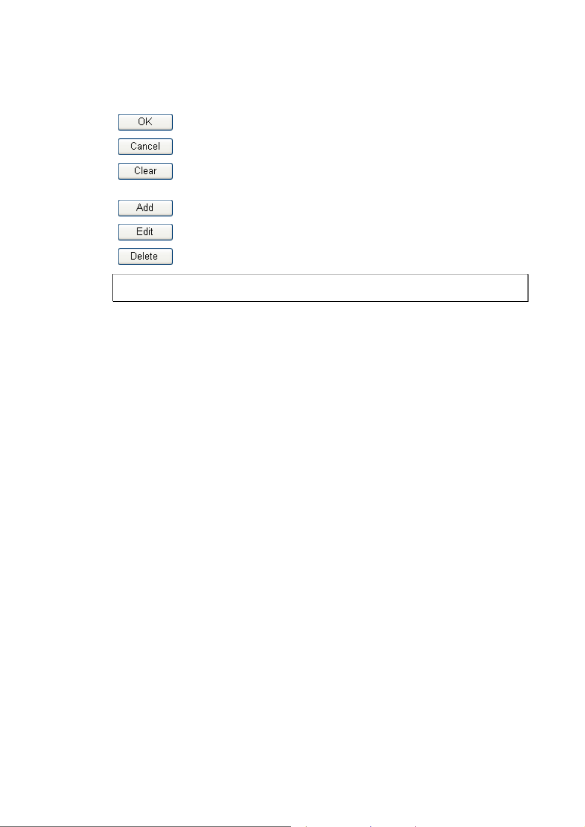
11..11 WWeebb CCoonnffiigguurraattiioonn BBuuttttoonnss EExxppllaannaattiioonn
Several main buttons appeared on the web pages are defined as the following:
Save and apply current settings.
Cancel current settings and recover to the previous saved settings.
Clear all the selections and parameters settings, including selection from
drop-down list. All the values must be reset with factory default settings.
Add new settings for specified item.
Edit the settings for the selected item.
Delete the selected item with the corresponding settings.
Note: For the other buttons shown on the web pages, please refer to the following chapters
for detailed explanation.
2
VigorFly 210 Series User’s Guide
Page 11
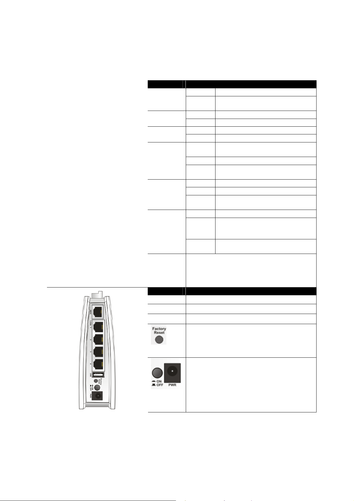
11..22 LLEEDD IInnddiiccaattoorrss aanndd CCoonnnneeccttoorrss
Before you use the Vigor router, please get acquainted with the LED indicators and connectors
first.
LED Status Explanation
Off The system is not ready or is failed. ACT
Blinking The system is ready and can work
On A USB device is connected and active.USB
Blinking The data is transmitting.
On The WAN port is connected. WAN
Blinking It will blink while transmitting data.
LAN 1 - 4
WLAN
(Blue LED)
on WLAN
button
WPS
(Orange
LED) on
WLAN
button
WPS Button Press this button for 2 seconds to wait for client
On A normal connection is through its
Off LAN is disconnected.
Blinking Data is transmitting
On Wireless access point is ready.
Off Wireless access point is not ready.
Blinking
(Blue)
Off The WPS is off.
Blinking
(Orange)
Blinking
(Orange)
device making network connection through WPS.
When the orange LED lights up, the WPS will be
on.
normally.
corresponding port.
(sending/receiving).
Blink when wireless traffic goes
through.
Blink with 1 second cycle for 2
minutes - - WPS is enabled and waiting
for wireless client to connect with it.
Blink when wireless traffic goes
through.
Interface Description
WAN Connector for accessing the Internet.
LAN (1-4) Connectors for local networked devices.
USB Connector for a printer or 3G backup.
Restore the default settings. Usage: Turn on the
router. Press the button and keep for more than 10
seconds. Then the router will restart with the
factory default configuration.
ON/OFF: Power switch.
PWR: Connecter for a power adapter.
VigorFly 210 Series User’s Guide
3
Page 12
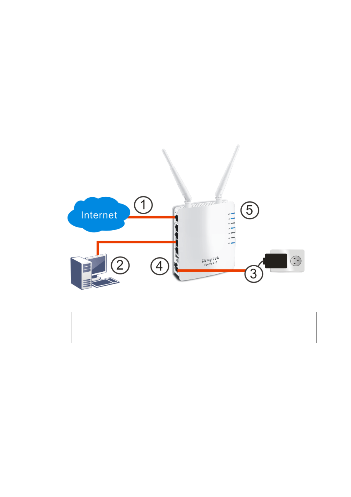
11..33 HHaarrddwwaarree IInnssttaallllaattiioonn
Before starting to configure the router, you have to connect your devices correctly.
1. Connect this device to a modem with an Ethernet cable.
2. Connect the LAN port to your computer with a RJ-45 cable.
3. Connect one end of the power adapter to the Power port of this device. Connect the other
end to the wall outlet of electricity.
4. Power on the router.
5. Check the ACT, WAN and LAN LEDs to assure network connections.
(For the detailed information of LED status, please refer to section 1.1.)
Note: To get a better WiMAX signal, please use a USB extension cable to connect USB
WiMAX dongle to Vigor router for increasing the distance between Vigor router and the
dongle.
4
VigorFly 210 Series User’s Guide
Page 13
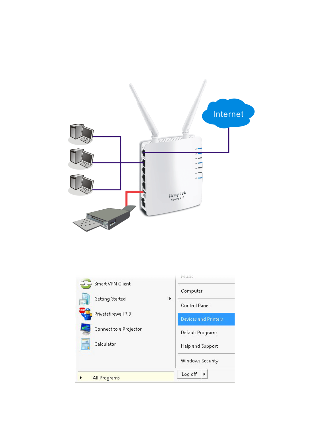
11..44 PPrriinntteerr IInnssttaallllaattiioonn
You can install a printer onto the router for sharing printing. All the PCs connected this router
can print documents via the router. The example provided here is made based on Windows 7.
For other Windows system, please visit www.draytek.com.
Before using it, please follow the steps below to configure settings for connected computers
(or wireless clients).
1. Connect the printer with the router through USB/parallel port.
2. Open All Programs>>Getting Started>>Devices and Printers.
VigorFly 210 Series User’s Guide
5
Page 14
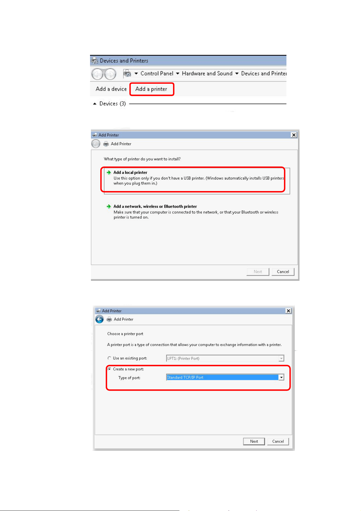
3. Click Add a printer.
4. A dialog will appear. Click Add a local printer and click Next.
5. In this dialog, choose Create a new port. In the field of Type of port, use the drop
down list to select Standard TCP/IP Port. Then, click Next.
6
VigorFly 210 Series User’s Guide
Page 15
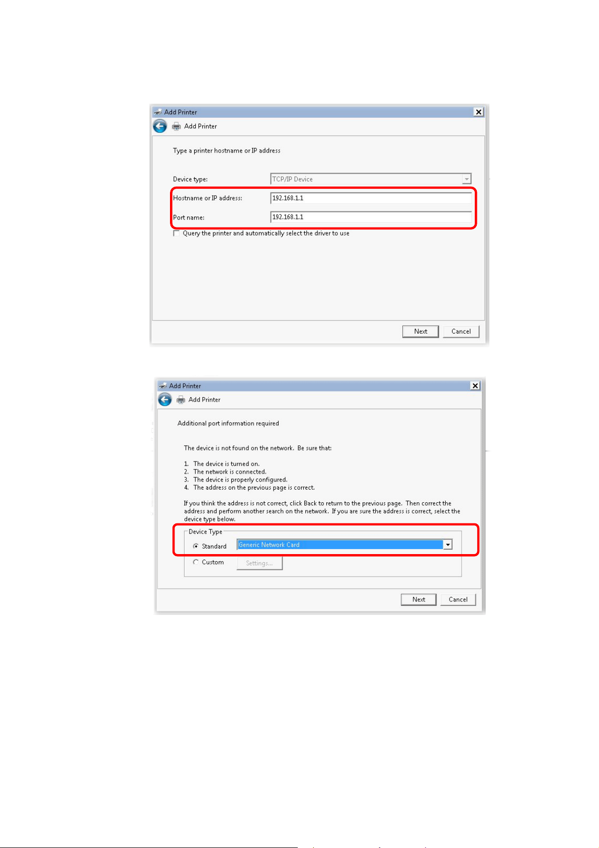
6. In the following dialog, type 192.168.1.1 (router’s LAN IP) in the field of Hostname or
IP Address and type 192.168.1.1 as the Port name. Then, click Next.
7. Click Standard and choose Generic Ne twork Card.
VigorFly 210 Series User’s Guide
7
Page 16
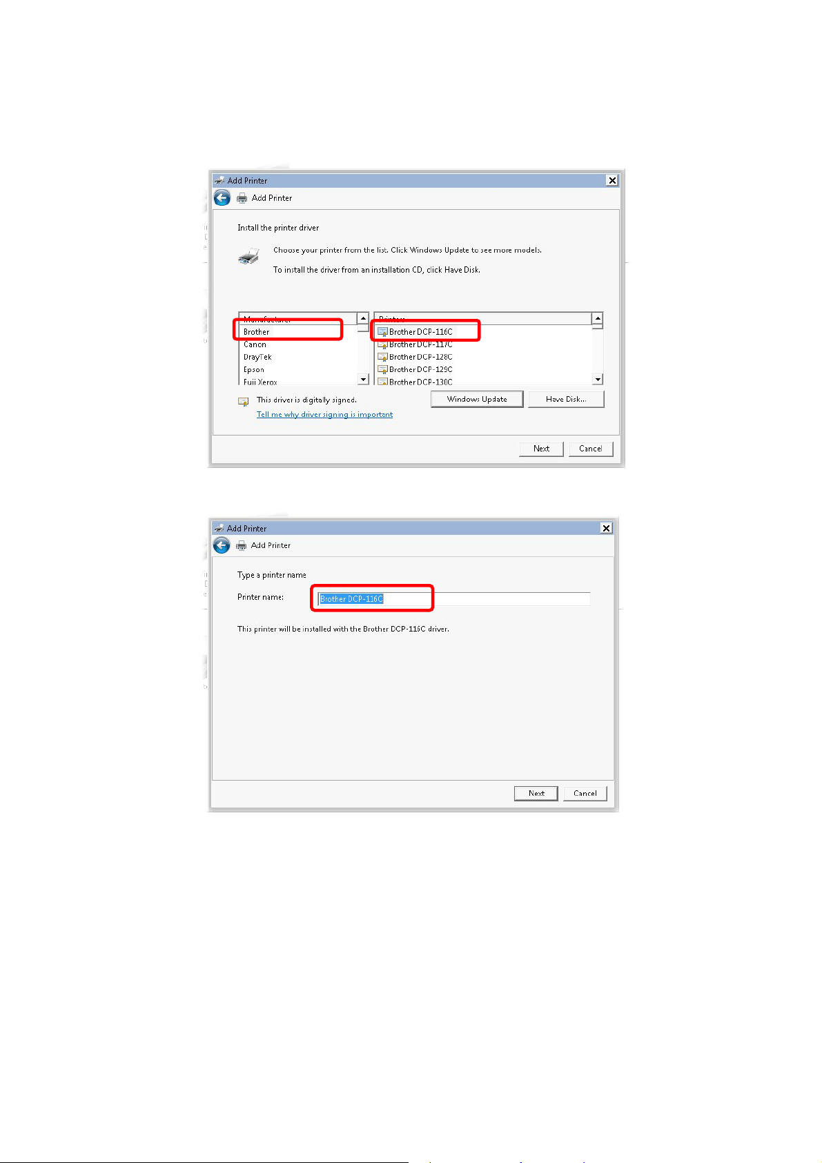
8. Now, your system will ask you to choose right name of the printer that you installed onto
the router. Such step can make correct driver loaded onto your PC. When you finish the
selection, click Next.
9. Type a name for the chosen printer. Click Next.
8
VigorFly 210 Series User’s Guide
Page 17
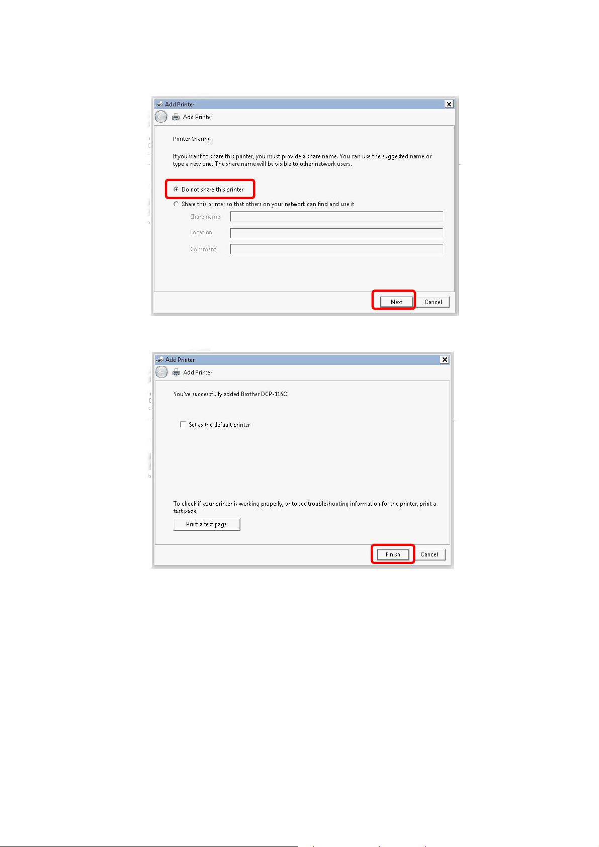
10. Choose Do not share this printer and click Next.
11. Then, in the following dialog, click Finish.
VigorFly 210 Series User’s Guide
9
Page 18
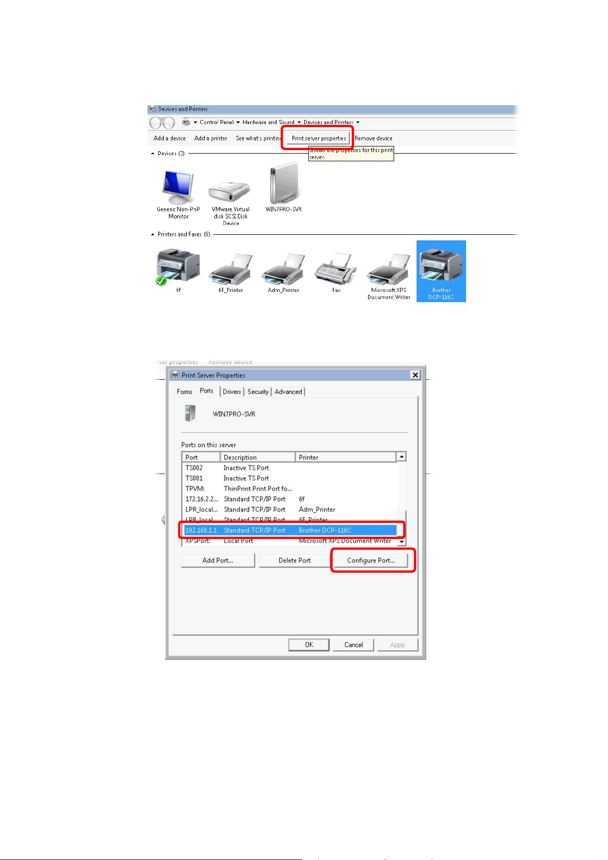
12. The new printer has been added and displayed under Printers and Faxes. Click the new
printer icon and click Printer server properties.
13. Edit the property of the new printer you have added by clicking Configure Port.
10
VigorFly 210 Series User’s Guide
Page 19
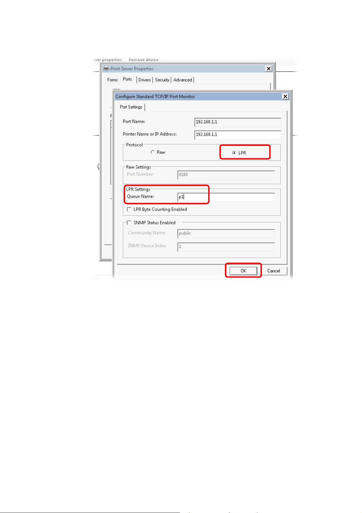
14. Select "LPR" on Protocol, type p1 (number 1) as Queue Name. Then click OK.
The printer can be used for printing now. Most of the printers with different manufacturers are
compatible with vigor router.
VigorFly 210 Series User’s Guide
11
Page 20
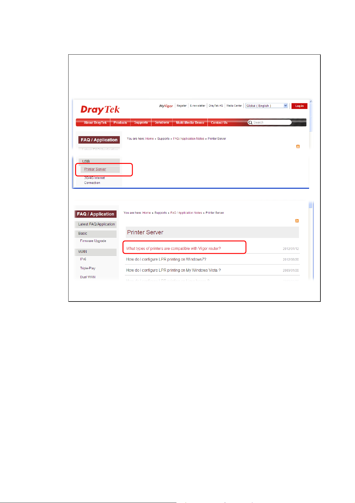
Note 1: Some printers with the fax/scanning or other additional functions are not supported.
If you do not know whether your printer is supported or not, please visit www.DrayTek.com
to find out the printer list. Open Support > FAQ/Application Notes; find out the link of
Printer Server and click it; then click the What types of printers are compatible with
Vigor router? link.
Then, click the What types of printers are compatible with Vigor router? link.
Note 2: Vigor router supports printing request from computers via LAN ports but not WAN
port.
12
VigorFly 210 Series User’s Guide
Page 21
Baassiicc
B
For using the router properly, it is necessary for you to change the password of web
configuration for security and adjust primary basic settings.
Seettttiinnggss
S
22..11 AAcccceessssiinngg WWeebb PPaaggee
1. Make sure your PC connects to the router correctly.
Notice: You may either simply set up your computer to get IP dynamically
from the router or set up the IP address of the computer to be the same subnet as
the default IP address of Vigor router 192.168.1.1. For the detailed
information, please refer to the later section - Trouble Shooting of the guide.
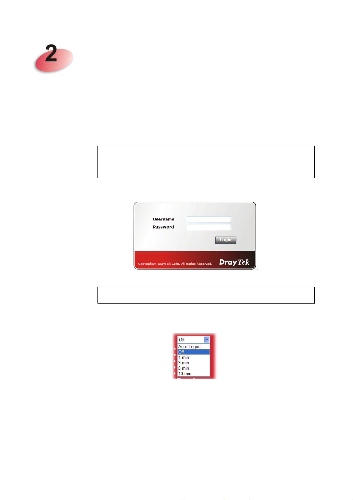
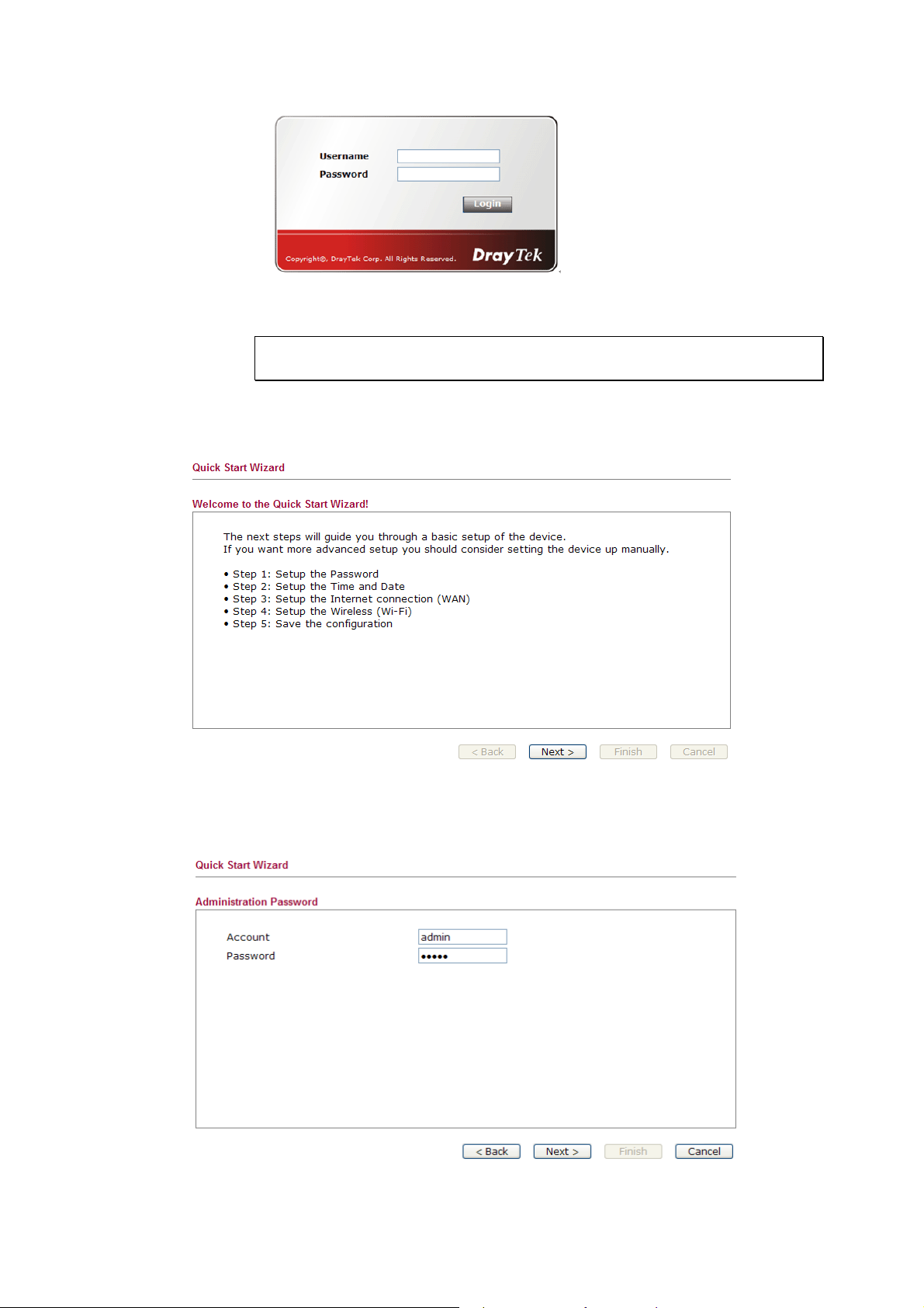
2. Open a web browser on your PC and type http://192.168.1.1. The following window
will be open to ask for username and password.
3. Type “admin/admin” on Username/Password and click Login for web configuration.
Notice: If you fail to access to the web configuration, please go to “Trouble
Shooting” for detecting and solving your problem.
4. The web page can be logged out according to the chosen condition. The default setting is
Auto Logout, which means the web configuration system will logout after 5 minutes
without any operation. Change the setting for your necessity.
VigorFly 210 Series User’s Guide
13
Page 22

22..22 CChhaannggiinngg PPaasssswwoorrdd
Before configuring the web pages, please change the password for the original security of the
router.
1. Open a web browser on your PC and type http://192.168.1.1. A pop-up window will
open to ask for username and password.
2. Please ty pe “admin/admin” on Username/Password for admin mode and click Login.
Note: The home page will change slightly in accordance with the type of the router
you have.
3. To change the password, please access into Admin Mode. Then, go to System
Maintenance page and choose Administration Password.
4. Type new user name in the field of Account and new password in the field of Password.
Then click OK to continue.
5. Now, the password has been changed. Next time, use the new username / password to
access the web user interface of this router.
14
VigorFly 210 Series User’s Guide
Page 23
22..33 QQuuiicckk SSttaarrtt WWiizzaarrdd
Notice: Quick Start Wizard for user mode operation is the same as for admin
mode operation.
If your router can be under an environment with high speed NAT, the configuration provide
here can help you to deploy and use the router quickly. The first screen of Quick Start
Wizard is welcome page, please click Next.
22..33..11 SSeettttiinngg uupp tthhee PPaasssswwoorrdd
The first screen of Quick Start Wizard is entering login account and password. After typing a
new password, please click Next.
VigorFly 210 Series User’s Guide
15
Page 24
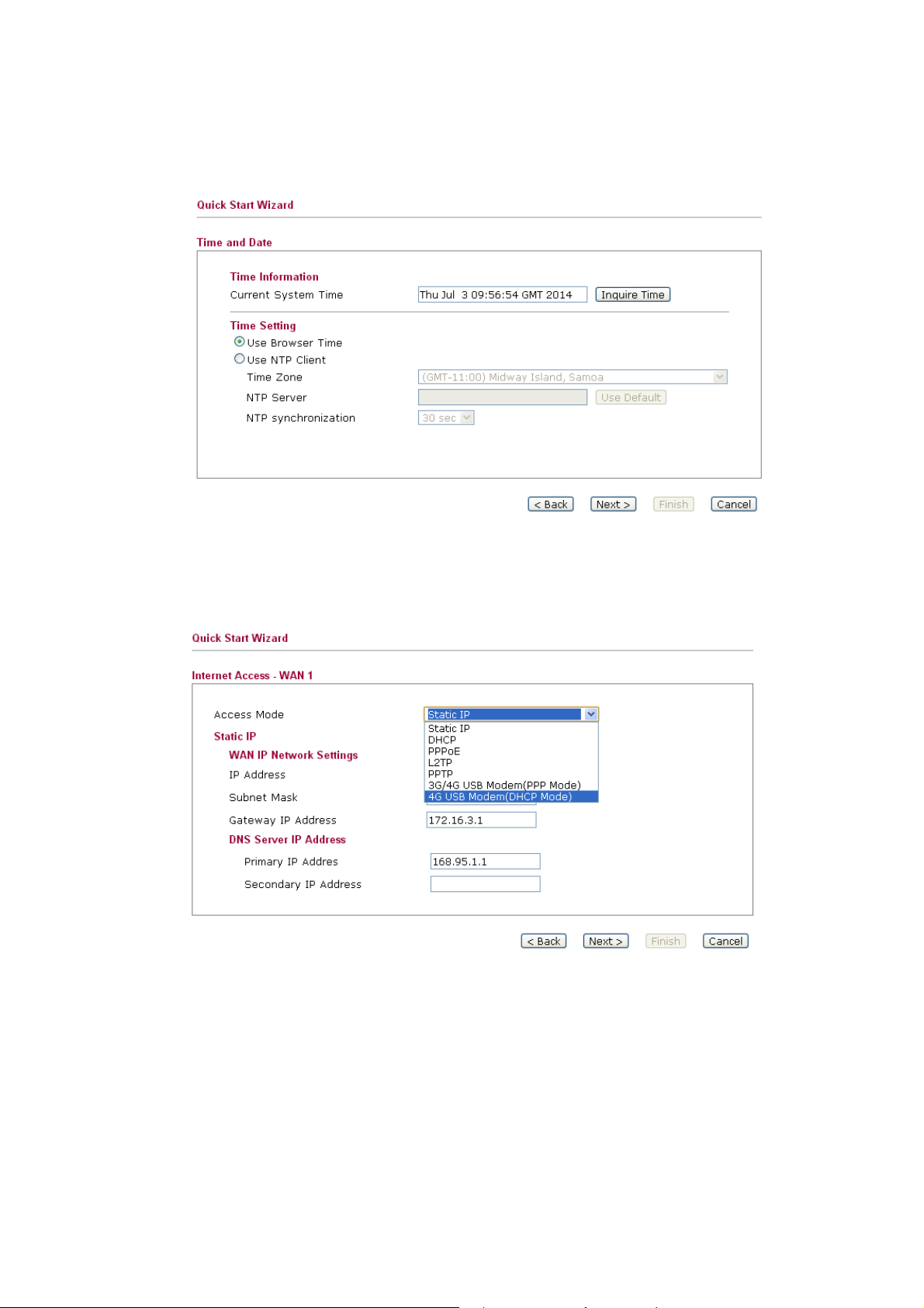
22..33..22 SSeettttiinngg uupp tthhee TTiimmee aanndd DDaattee
On the next page as shown below, please select the Time Zone for the router installed and
specify the NTP server(s). Then click Next for next step.
22..33..33 SSeettttiinngg uupp tthhee IInntteerrnneett CCoonnnneeccttiioonn ffoorr WWAANN11
On the next page as shown below, please select the appropriate connection type according to
the information from your ISP. There are several types offered in this page. Each connection
type will bring out different web page.
16
VigorFly 210 Series User’s Guide
Page 25
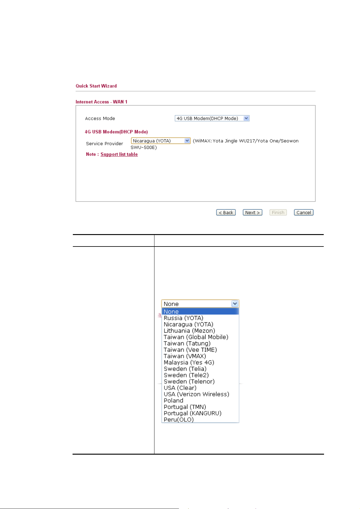
44GG UUSSBB MMooddeemm ((DDHHCCPP MMooddee))
If you want to access Internet with 4G USB Modem, choose 4G USB Modem as the Access
Mode. Corresponding settings will be displayed for you to configure.
Available parameters are listed below:
Item Description
Service Provider
Choose the local service provider which can serve network
service according to the nature of USB Modem
(LTE/WiMAX) installed. For example, you live in Taiwan
and have a WiMAX modem inserted onto VigorFly 210.
You can choose Taiwan (Global Mobile) to configure
necessary settings and then surf the Internet easily.
VigorFly 210 Series User’s Guide
The available settings will be different based on the service
provider specified. In this case, Taiwan (Global Mobile) is
chosen as an example.
17
Page 26
Item Description
Username
Password
Cipher Suite
Type the user name acquired from the service provider.
Type the password acquired from the service provider.
Cipher Suite – There are two encryption methods offered
for you to choose as cipher suite. Keep the default setting
will be better. Such item is required for WiMAX USB
Modem.
After finishing the settings here, please click Next.
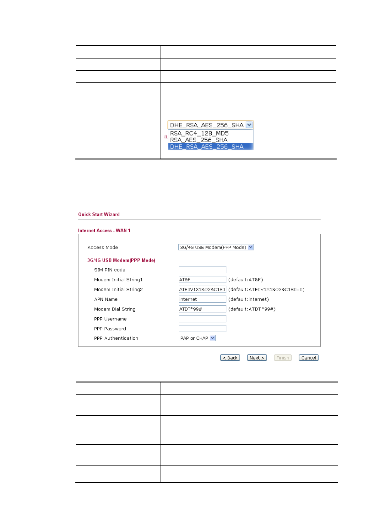
33GG//44GG UUSSBB MMooddeemm ((PPPPPP MMooddee))
If you want to access Internet by 3G USB modem, choose this mode as the protocol and type
the required information in this web page.
Available parameters are listed below:
Item Description
SIM PIN code
Type PIN code of the SIM card that will be used to access
Internet.
Modem Initial String1/2
Such value is used to initialize USB modem. Please use the
default value. If you have any question, please contact to
your ISP.
APN Name
APN means Access Point Name which is provided and
required by some ISPs.
Modem Dial String
Such value is used to dial through USB mode. Please use the
default value. If you have any question, please contact to
18
VigorFly 210 Series User’s Guide
Page 27
Item Description
your ISP.
PPP Username
PPP Password
PPP Authentication
Type the PPP username (optional).
Type the PPP password (optional).
Select PAP only or PAP or CHAP for PPP.
After finishing the settings here, please click Next.
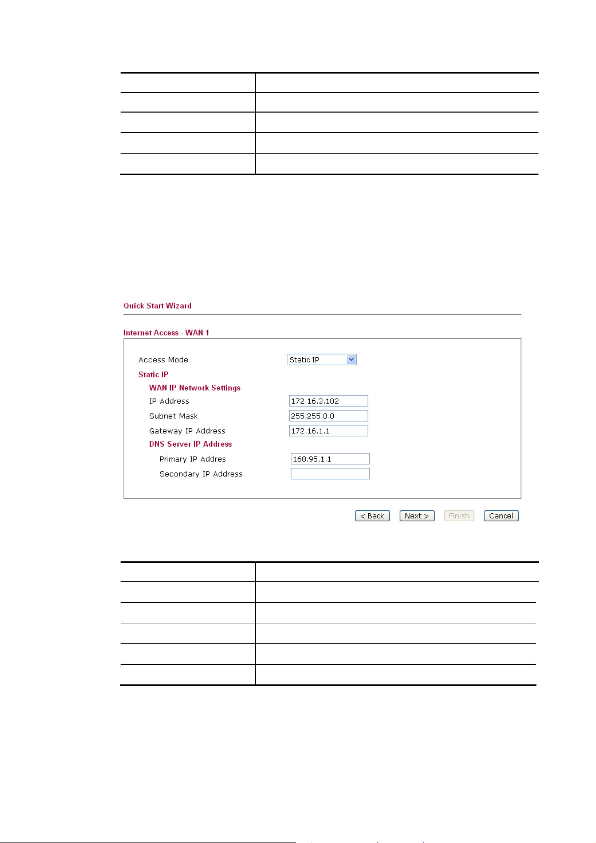
SSttaattiicc IIPP
You will receive a fixed public IP address or a public subnet, namely multiple public IP
addresses from your DSL or Cable ISP service providers. In most cases, a Cable service
provider will offer a fixed public IP, while a DSL service provider will offer a public subnet.
If you have a public subnet, you could assign an IP address or many IP address to the WAN
interface.
Available parameters are listed below:
Item Description
IP Address
Subnet Mask
Default Gateway
Primary DNS Server
Secondary DNS Server
After finishing the settings here, please click Next.
VigorFly 210 Series User’s Guide
Type the IP address.
Type the subnet mask.
Type the gateway IP address.
Type in the primary IP address for the router.
Type in secondary IP address for necessity in the future.
19
Page 28
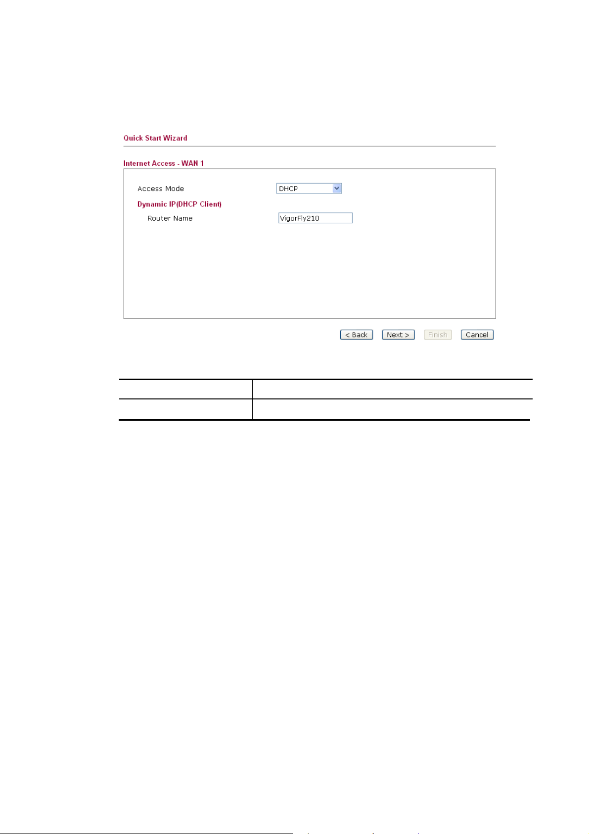
DDHHCCPP
It is not necessary for you to type any IP address manually. Simply choose this type and the
system will obtain the IP address automatically from DHCP server.
Available parameters are listed below:
Item Description
Router Name
Default setting is VigorFly210.
After finishing the settings here, please click Next.
20
VigorFly 210 Series User’s Guide
Page 29
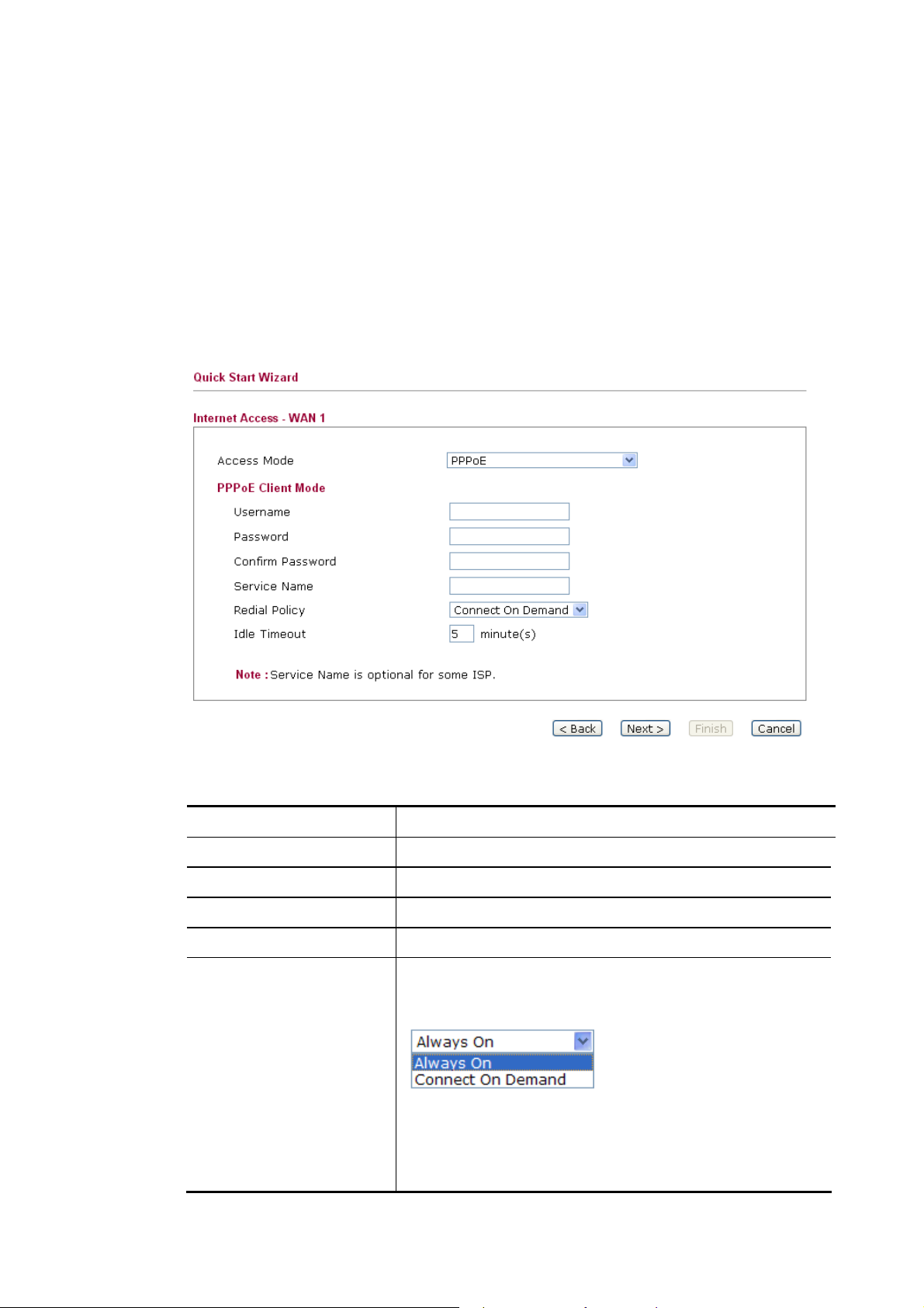
PPPPPPooEE
PPPoE stands for Point-to-Point Protocol over Ethernet. It relies on two widely accepted
standards: PPP and Ethernet. It connects users through an Ethernet to the Internet with a
common broadband medium, such as a single DSL line, wireless device or cable modem. All
the users over the Ethernet can share a common connection.
PPPoE is used for most of DSL modem users. All local users can share one PPPoE connection
for accessing the Internet. Your service provider will provide you information about user name,
password, and authentication mode.
If your ISP provides you the PPPoE connection, please select PPPoE for this router. The
following page will be shown:
Available parameters are listed below:
Item Description
User Name
Password
Confirmed Password
Service Name
Redial Policy
Assign a specific valid user name provided by the ISP.
Assign a valid password provided by the ISP.
Type the password again for confirmation.
Type the description of the specific network service.
If you want to connect to Internet all the time, you can
choose Always On. Otherwise, choose Connect on
Demand.
Always On – Choose it to enable router always keep
connection.
Connect On Demand - If the connection has been idled
over the value, the router will drop the connection.
VigorFly 210 Series User’s Guide
21
Page 30
Item Description
Idle Timeout - Set the timeout for breaking down the
Internet after passing through the time without any action.
The unit is seconds.
After finishing the settings here, please click Next.
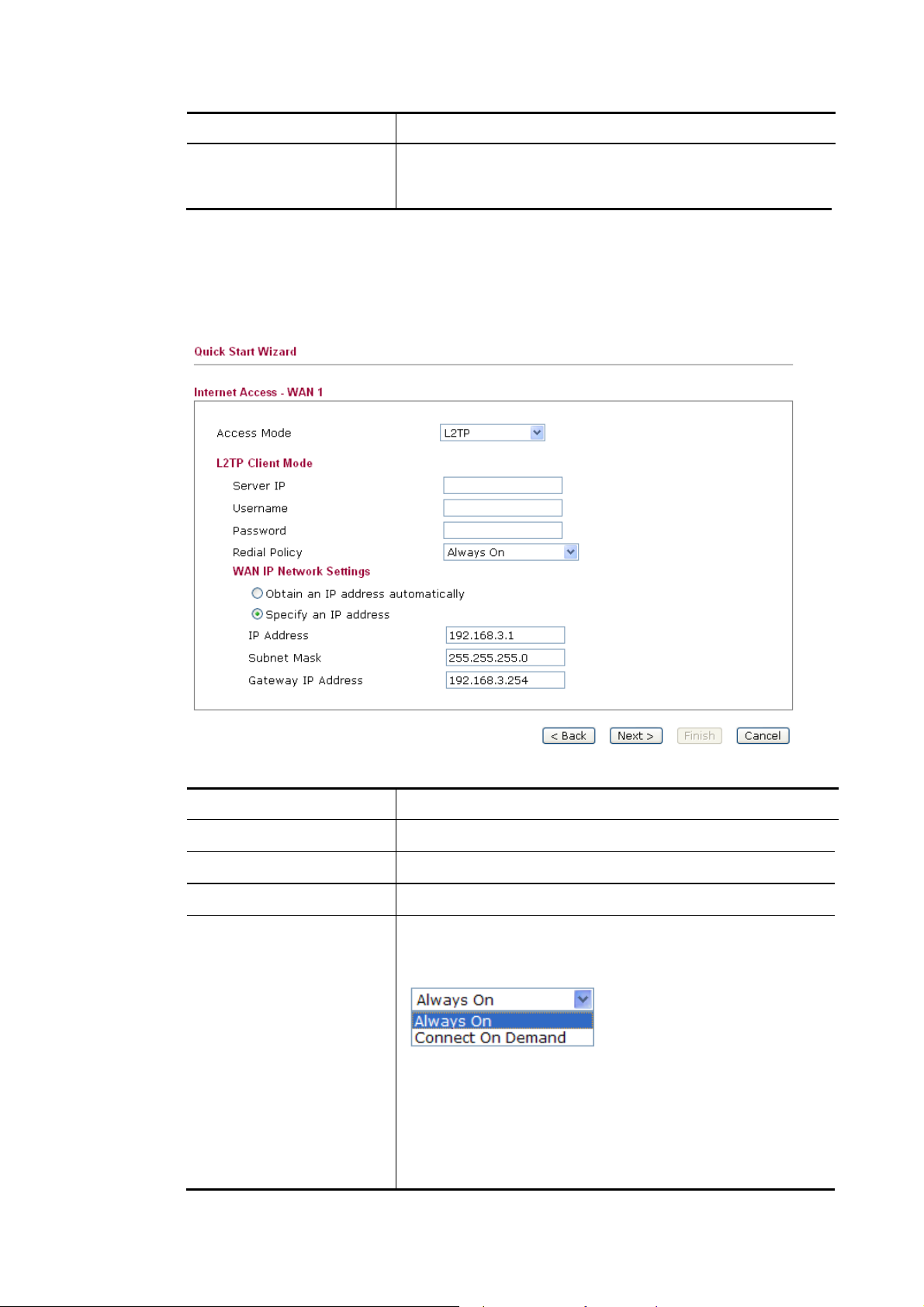
PPPPTTPP//LL22TTPP
If you click PPTP/L2TP as the connection type, please manually enter the Username/Password
provided by your ISP and all the required information.
Available parameters are listed below:
Item Description
L2TP/PPTP Server IP
Username
Password
Redial Policy
Specify the IP address of the PPTP/L2TP server.
Assign a specific valid user name provided by the ISP.
Assign a valid password provided by the ISP.
If you want to connect to Internet all the time, you can
choose Always On. Otherwise, choose Connect on
Demand.
Always On – Choose it to enable router always keep
connection.
Connect On Demand - If the connection has been idled over
the value, the router will drop the connection.
Idle Timeout - Set the timeout for breaking down the
Internet after passing through the time without any action.
22
VigorFly 210 Series User’s Guide
Page 31

Item Description
The unit is seconds.
WAN IP Network
Settings
IP Address
Subnet Mask
Redial Policy
After finishing the settings here, please click Next.
You can choose Obtain an IP address automatically or
Specify an IP address as address mode setting.
Type the IP address if you choose Static IP as the WAN IP
network setting.
Type the subnet mask if you chose Static IP as the WAN IP.
If you want to connect to Internet all the time, you can
choose Always On.
22..33..44 SSeettttiinngg uupp tthhee IInntteerrnneett CCoonnnneeccttiioonn ffoorr WWAANN22
WAN 2 is only used for backup WAN1 interface. You will get different web settings
according to the service provider specified.
33GG//44GG UUSSBB MMooddeemm ((PPPPPP MMooddee))
If you want to access Internet by 3G USB modem, choose this mode as the protocol and type
the required information in this web page.
VigorFly 210 Series User’s Guide
23
Page 32
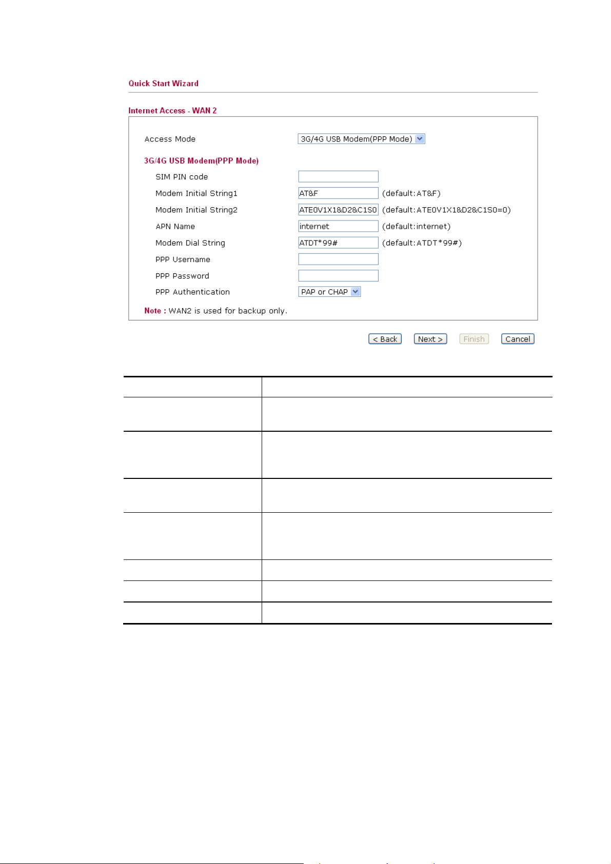
Available parameters are listed below:
Item Description
SIM PIN code
Type PIN code of the SIM card that will be used to access
Internet.
Modem Initial String1/2
Such value is used to initialize USB modem. Please use the
default value. If you have any question, please contact to
your ISP.
APN Name
APN means Access Point Name which is provided and
required by some ISPs.
Modem Dial String
Such value is used to dial through USB mode. Please use the
default value. If you have any question, please contact to
your ISP.
PPP Username
PPP Password
PPP Authentication
Type the PPP username (optional).
Type the PPP password (optional).
Select PAP only or PAP or CHAP for PPP.
After finishing the settings here, please click Next.
24
VigorFly 210 Series User’s Guide
Page 33
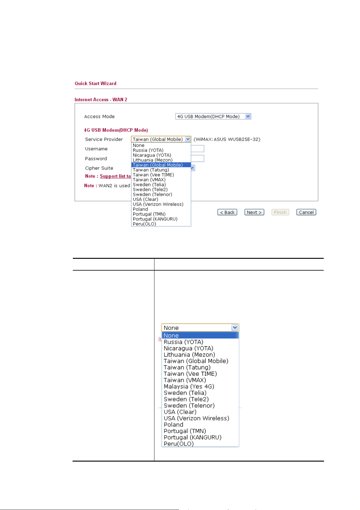
44GG UUSSBB MMooddeemm ((DDHHCCPP MMooddee))
If you want to access Internet with 4G USB Modem, choose 4G USB Modem as the Access
Mode. Corresponding settings will be displayed for you to configure.
Available parameters are listed below:
Item Description
Service Provider
Choose the local service provider which can serve network
service according to the nature of USB Modem
(LTE/WiMAX) installed. For example, you live in Taiwan
and have a WiMAX modem inserted onto VigorFly 210.
You can choose Taiwan (Global Mobile) to configure
necessary settings and then surf the Internet easily.
VigorFly 210 Series User’s Guide
The available settings will be different based on the service
25
Page 34
Item Description
provider specified. In this case, Taiwan (Global Mobile) is
chosen as an example.
Username
Password
Cipher Suite
Type the user name acquired from the service provider.
Type the password acquired from the service provider.
Cipher Suite – There are two encryption methods offered
for you to choose as cipher suite. Keep the default setting
will be better. Such item is required for WiMAX USB
Modem.
After finishing the settings here, please click Next.
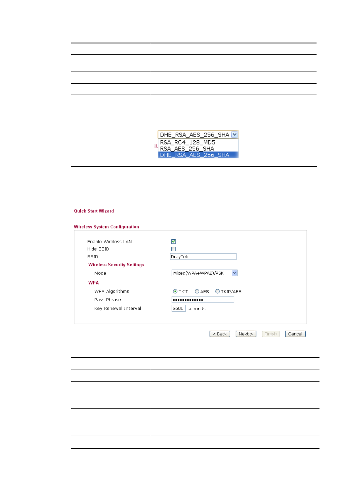
22..33..55 SSeettttiinngg uupp tthhee WWiirreelleessss CCoonnnneeccttiioonn
Now, you have to set up the wireless connection.
Available parameters are listed below:
Item Description
Enable Wireless LAN
Hide SSID
Check the box to enable the wireless function.
Check this box to prevent from wireless sniffing and make it
harder for unauthorized clients or STAs to join your wireless
LAN.
SSID
It means the identification of the wireless LAN. SSID can be
any text numbers or various special characters. The default
SSID is "DrayTek". We suggest you to change it.
Mode
Choose the wireless mode for this router.
26
VigorFly 210 Series User’s Guide
Page 35
Item Description
Each encryption mode will bring out different web page and
ask you to offer additional configuration.
After finishing the settings here, please click Next.
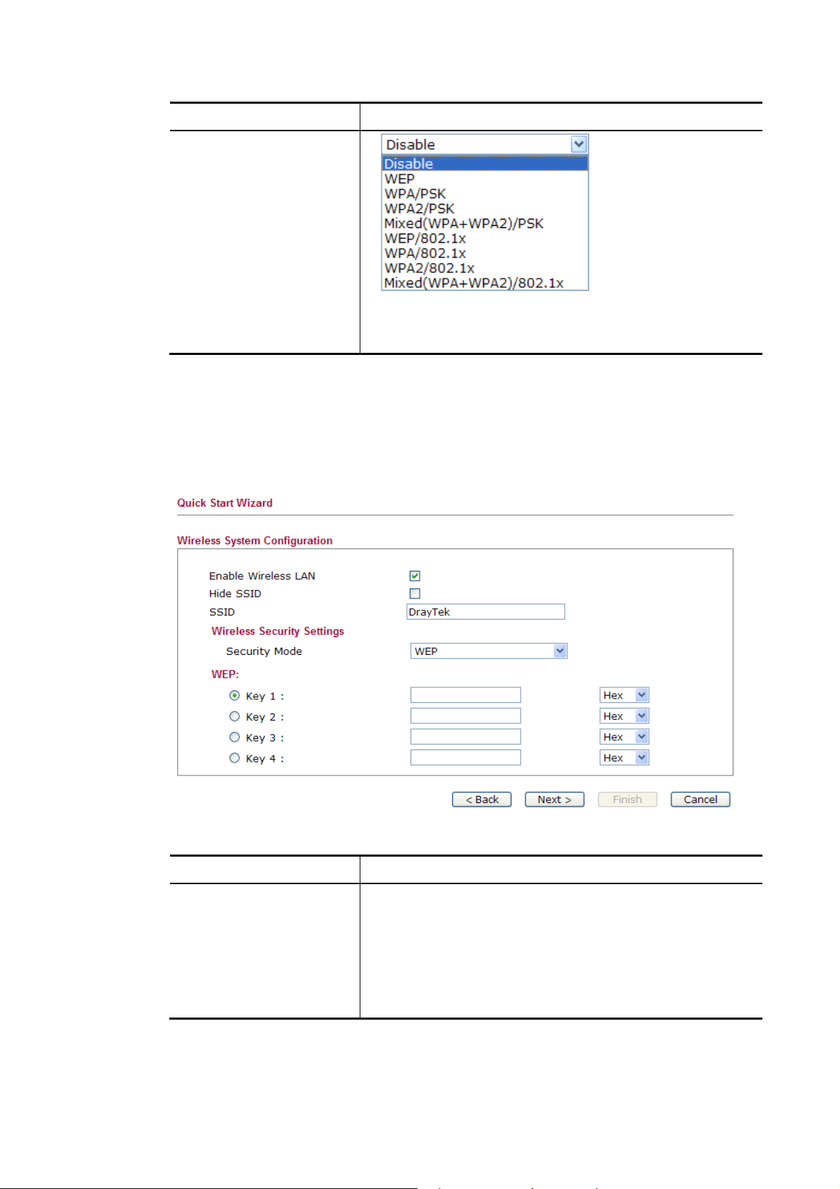
WWEEPP
If you choose WEP as the security configuration, you have to specify encryption key (Key 1 ~
Key 4) and authentication mode (open or shared). All wireless devices must support the same
WEP encryption bit size and have the same key.
Available parameters are listed below:
Item Description
Key 1 ~ Key 4
After finishing the settings here, please click Next.
VigorFly 210 Series User’s Guide
Four keys can be entered here, but only one key can be
selected at a time. The format of WEP Key is restricted to 5
ASCII characters or 10 hexadecimal values in 64-bit
encryption level, or restricted to 13 ASCII characters or 26
hexadecimal values in 128-bit encryption level. The allowed
content is the ASCII characters from 33(!) to 126(~) except '#'
and ','.
27
Page 36

WWPPAA//PPSSKK oorr WWPPAA22//PPSSKK oorr MMiixxeedd ((WWPPAA++WWPPAA22))//PPSSKK
Accepts only WPA clients and the encryption key should be entered in PSK. The WPA
encrypts each frame transmitted from the radio using the key, which either PSK (Pre-Shared
Key) entered manually in this field below or automatically negotiated via 802.1x
authentication.
Available parameters are listed below:
Item Description
WPA Algorithm
Pass Phrase
Choose the WPA algorithm, TKIP, AES or TKIP/AES.
Either 8~63 ASCII characters, such as 012345678..(or 64
Hexadecimal digits leading by 0x, such as
"0x321253abcde...").
Key Renewal Interval
WPA uses shared key for authentication to the network.
However, normal network operations use a different
encryption key that is randomly generated. This randomly
generated key that is periodically replaced. Enter the renewal
security time (seconds) in the column. Smaller interval leads
to greater security but lower performance. Default is 3600
seconds. Set 0 to disable re-key.
After finishing the settings here, please click Next.
28
VigorFly 210 Series User’s Guide
Page 37

WWEEPP//880022..11xx
Remote Authentication Dial-In User Service (RADIUS) is a security authentication
client/server protocol that supports authentication, authorization and accounting, which is
widely used by Internet service providers. It is the most common method of authenticating and
authorizing dial-up and tunneled network users.
The built-in RADIUS client feature enables the router to assist the remote dial-in user or a
wireless station and the RADIUS server in performing mutual authentication. It enables
centralized remote access authentication for network management.
If you choose WPA-Radius as the security configuration, you have to specify WPA mode,
algorithm, Radius server, Radius server port and Radius server secret respectively.
Available parameters are listed below:
Item Description
WEP
Disable - Disable the WEP Encryption. Data sent to the AP
will not be encrypted.
Enable - Enable the WEP Encryption.
IP Address
Port
Enter the IP address of RADIUS server.
The UDP port number that the RADIUS server is using. The
default value is 1812, based on RFC 2138.
Shared Secret
The RADIUS server and client share a secret that is used to
authenticate the messages sent between them. Both sides
must be configured to use the same shared secret.
Session Timeout
Set the maximum time of service provided before
re-authentication. Set to zero to perform another
authentication immediately after the first authentication has
successfully completed. (The unit is second.)
Idle Timeout
Set the maximum time that a wireless device may remain
idle. (The unit is second.)
VigorFly 210 Series User’s Guide
29
Page 38

WWPPAA//880022..11xx
The WPA encrypts each frame transmitted from the radio using the key, which either PSK
(Pre-Shared Key) entered manually in this field below or automatically negotiated via 802.1x
authentication.
Available parameters are listed below:
Item Description
WPA Algorithms
Key Renewal Interval
Select TKIP, AES or TKIP/AES as the algorithm for WPA.
WPA uses shared key for authentication to the network.
However, normal network operations use a different
encryption key that is randomly generated. This randomly
generated key that is periodically replaced. Enter the renewal
security time (seconds) in the column. Smaller interval leads
to greater security but lower performance. Default is 3600
seconds. Set 0 to disable re-key.
IP Address
Port
Enter the IP address of RADIUS server.
The UDP port number that the RADIUS server is using. The
default value is 1812, based on RFC 2138.
Shared Secret
The RADIUS server and client share a secret that is used to
authenticate the messages sent between them. Both sides
must be configured to use the same shared secret.
Session Timeout
Set the maximum time of service provided before
re-authentication. Set to zero to perform another
authentication immediately after the first authentication has
successfully completed. (The unit is second.)
Idle Timeout
Set the maximum time that a wireless device may remain
idle. (The unit is second.)
30
VigorFly 210 Series User’s Guide
Page 39
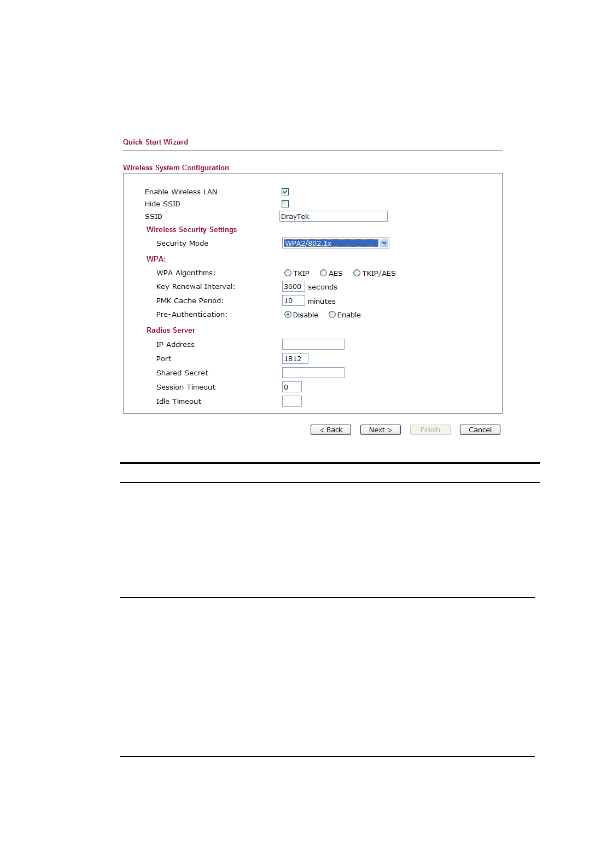
WWPPAA22//880022..11xx
The WPA encrypts each frame transmitted from the radio using the key, which either PSK
(Pre-Shared Key) entered manually in this field below or automatically negotiated via 802.1x
authentication.
Available parameters are listed below:
Item Description
WPA Algorithms
Key Renewal Interval
Select TKIP, AES or TKIP/AES as the algorithm for WPA.
WPA uses shared key for authentication to the network.
However, normal network operations use a different
encryption key that is randomly generated. This randomly
generated key that is periodically replaced. Enter the renewal
security time (seconds) in the column. Smaller interval leads
to greater security but lower performance. Default is 3600
seconds. Set 0 to disable re-key.
PMK Cache Period
Set the expire time of WPA2 PMK (Pairwise master key)
cache. PMK Cache manages the list from the BSSIDs in the
associated SSID with which it has pre-authenticated.
Pre-Authentication
Enables a station to authenticate to multiple APs for roaming
securer and faster. With the pre-authentication procedure
defined in IEEE 802.11i specification, the
pre-four-way-handshake can reduce handoff delay
perceivable by a mobile node. It makes roaming faster and
more secure. (Only valid in WPA2)
Enable - Enable IEEE 802.1X Pre-Authentication.
Disable - Disable IEEE 802.1X Pre-Authentication.
VigorFly 210 Series User’s Guide
31
Page 40
Item Description
IP Address
Port
Enter the IP address of RADIUS server.
The UDP port number that the RADIUS server is using. The
default value is 1812, based on RFC 2138.
Shared Secret
The RADIUS server and client share a secret that is used to
authenticate the messages sent between them. Both sides
must be configured to use the same shared secret.
Session Timeout
Set the maximum time of service provided before
re-authentication. Set to zero to perform another
authentication immediately after the first authentication has
successfully completed. (The unit is second.)
Idle Timeout
Set the maximum time that a wireless device may remain
idle. (The unit is second.)
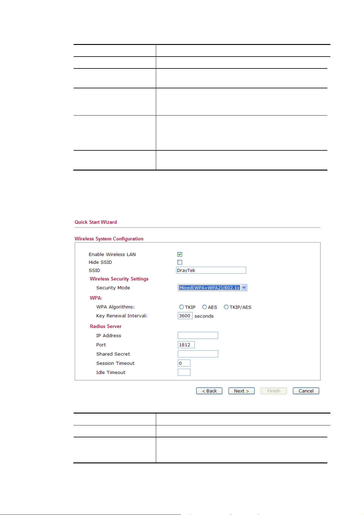
MMiixxeedd ((WWPPAA++WWPPAA22))//880022..11xx
The WPA encrypts each frame transmitted from the radio using the key, which either PSK
(Pre-Shared Key) entered manually in this field below or automatically negotiated via 802.1x
authentication.
Available parameters are listed below:
Item Description
WPA Algorithms
Key Renewal Interval
Select TKIP, AES or TKIP/AES as the algorithm for WPA.
WPA uses shared key for authentication to the network.
However, normal network operations use a different
encryption key that is randomly generated. This randomly
32
\
VigorFly 210 Series User’s Guide
Page 41
Item Description
generated key that is periodically replaced. Enter the renewal
security time (seconds) in the column. Smaller interval leads
to greater security but lower performance. Default is 3600
seconds. Set 0 to disable re-key.
IP Address
Port
Enter the IP address of RADIUS server.
The UDP port number that the RADIUS server is using. The
default value is 1812, based on RFC 2138.
Shared Secret
The RADIUS server and client share a secret that is used to
authenticate the messages sent between them. Both sides
must be configured to use the same shared secret.
Session Timeout
Set the maximum time of service provided before
re-authentication. Set to zero to perform another
authentication immediately after the first authentication has
successfully completed. (The unit is second.)
Idle Timeout
Set the maximum time that a wireless device may remain
idle. (The unit is second.)
After finishing the settings here, please click Next.
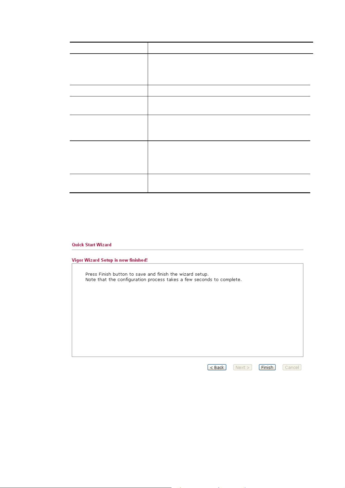
22..33..66 SSaavviinngg tthhee WWiizzaarrdd CCoonnffiigguurraattiioonn
Now you can see the following screen. It indicates that the setup is complete. Different types
of connection modes will have different summary. Click Finish and then restart the router.
VigorFly 210 Series User’s Guide
33
Page 42

22..44 OOnnlliinnee SSttaattuuss
The online status shows the system status, WAN status, and other status related to this router
within one page. If you select PPPoE as the protocol, you will find out a link of Dial PPPoE
or Drop PPPoE in the Online Status web page.
Detailed explanation is shown below:
Item Description
LAN Status IP Address
- Displays the IP address of the LAN interface.
TX Packets
- Displays the total transmitted packets at the LAN interface.
RX Packets
- Displays the total number of received packets at the LAN
interface.
TX Bytes
- Displays the total transmitted rate at the LAN interface.
RX Bytes
- Displays the total number of received rate at the LAN
interface.
WAN Status IP
- Displays the IP address of the WAN interface.
GW IP
- Displays the IP address of the default gateway.
Mode
- Displays the type of WAN connection (e.g., PPPoE).
Up Time
34
VigorFly 210 Series User’s Guide
Page 43

- Displays the total uptime of the interface.
Primary DNS
- Displays the primary DNS setting.
Secondary DNS
- Displays the secondary DNS setting.
TX Packets
- Displays the total transmitted packets at the WAN
interface.
TX Rate
- Displays the speed of transmitted octets at the WAN
interface.
RX Packets
- Displays the total number of received packets at the WAN
interface.
RX Rate
- Displays the speed of received octets at the WAN interface.
IPv6 Address
- Display the IP address for Ipv6 protocol.
4G USB Modem 4G USB Modem
- Display if such modem is connected or not.
Status
- Display the connection status
(Disconnected/Connecting/Operational) for the connected
dongle.
Base Station ID
- Display the MAC address of the remote base station.
Signal Strength (RSSI)
- Display the strength of the wireless signal.
Signal Quality (CINR)
- Display the quality of the wireless signal. The larger the
value number is, the better the quality shall be.
Note: The words in green mean that the WAN connection of that interface is ready for
accessing Internet; the words in red mean that the WAN connection of that interface is not
ready for accessing Internet.
22..55 SSaavviinngg CCoonnffiigguurraattiioonn
Each time you click OK on the web page for saving the configuration, you can find messages
showing the system interaction with you.
Ready indicates the system is ready for you to input settings.
Settings Saved means your settings are saved once you click Finish or OK button.
VigorFly 210 Series User’s Guide
35
Page 44

22..66 RReeggiisstteerriinngg VViiggoorr RRoouutteerr
You have finished the configuration of Quick Start Wizard and you can surf the Internet at any
time. Now it is the time to register your Vigor router to MyVigor website for getting more
service. Please follow the steps below to finish the router registration.
1. Please login the web configuration interface of Vigor router by typing “admin/admin”
as User Name / Password.
2. Click Support Area>>Production Registration from the home page.
3. A Login page will be shown on the screen. Please type the account and password that
you created previously. And click Login.
36
VigorFly 210 Series User’s Guide
Page 45

4. The following page will be displayed after you logging in MyVigor. From this page,
please click Add.
5. When the following page appears, please type in Nickname (for the router) and choose
the right registration date from the popup calendar (it appears when you click on the box
of Registration Date). After adding the basic information for the router, please click
Submit.
6. When the following page appears, your router information has been added to MyVigor
database.
VigorFly 210 Series User’s Guide
37
Page 46

7. Click OK. Now, you have finished the product registration.
38
VigorFly 210 Series User’s Guide
Page 47

Addvvaanncceedd
A
This chapter will guide users to execute advanced (full) configuration through admin mode
operation.
1. Open a web browser on your PC and type http://192.168.1.1. The window will ask for
typing username and password.
2. Please type “admin/admin” on Username/Password for administration operation.
Now, the Main Screen will appear. Be aware that “Admin mode” will be displayed on the
bottom left side.
Weebb
W
Coonnffiigguurraattiioonn
C
33..11 WWAANN
VigorFly 210 Series User’s Guide
Quick Start Wizard offers user an easy method to quick setup the connection mode for the
router. Moreover, if you want to adjust more settings for different WAN modes, please go to
Internet Access group.
BBaassiiccss ooff IInntteerrnneett PPrroottooccooll ((IIPP)) NNeettwwoorrkk
IP means Internet Protocol. Every device in an IP-based Network including routers, print
server, and host PCs, needs an IP address to identify its location on the network. To avoid
address conflicts, IP addresses are publicly registered with the Network Information Centre
(NIC). Having a unique IP address is mandatory for those devices participated in the public
network but not in the private TCP/IP local area networks (LANs), such as host PCs under the
management of a router since they do not need to be accessed by the public. Hence, the NIC
has reserved certain addresses that will never be registered publicly. These are known as
private IP addresses, and are listed in the following ranges:
39
Page 48

From 10.0.0.0 to 10.255.255.255
From 172.16.0.0 to 172.31.255.255
From 192.168.0.0 to 192.168.255.255
WWhhaatt aarree PPuubblliicc IIPP AAddddrreessss aanndd PPrriivvaattee IIPP AAddddrreessss
As the router plays a role to manage and further protect its LAN, it interconnects groups of
host PCs. Each of them has a private IP address assigned by the built-in DHCP server of the
Vigor router. The router itself will also use the default private IP address: 192.168.1.1 to
communicate with the local hosts. Meanwhile, Vigor router will communicate with other
network devices through a public IP address. When the data flow passing through, the
Network Address Translation (NAT) function of the router will dedicate to translate
public/private addresses, and the packets will be delivered to the correct host PC in the local
area network. Thus, all the host PCs can share a common Internet connection.
GGeett YYoouurr PPuubblliicc IIPP AAddddrreessss ffrroomm IISSPP
In ADSL deployment, the PPP (Point to Point)-style authentication and authorization is
required for bridging customer premises equipment (CPE). Point to Point Protocol over
Ethernet (PPPoE) connects a network of hosts via an access device to a remote access
concentrator or aggregation concentrator. This implementation provides users with significant
ease of use. Meanwhile it provides access control, billing, and type of service according to
user requirement.
When a router begins to connect to your ISP, a serial of discovery process will occur to ask for
a connection. Then a session will be created. Your user ID and password is authenticated via
PAP or CHAP with RADIUS authentication system. And your IP address, DNS server, and
other related information will usually be assigned by your ISP.
m
NNeettwwoorrkk CCoonnnneeccttiioonn bbyy 33GG UUSSBB MMooddeem
For 3G mobile communication through Access Point is popular more and more, Vigor router
adds the function of 3G network connection for such purpose. By connecting 3G USB Modem
to the USB port of Vigor router, it can support HSDPA/UMTS/EDGE/GPRS/GSM and the
future 3G standard (HSUPA, etc). Vigor router with 3G USB Modem allows you to receive
3G signals at any place such as your car or certain location holding outdoor activity and share
the bandwidth for using by more people. Users can use four LAN ports on the router to access
Internet. Also, they can access Internet via wireless function of Vigor router, and enjoy the
powerful firewall, bandwidth management features of Vigor router.
3G USB Modem can be used as backup device. Therefore, when WAN is not available, the
router will use 3G USB Modem for supporting automatically. The supported 3G USB Modem
will be listed on DrayTek web site. Please visit www.draytek.com for more detailed
information.
40
VigorFly 210 Series User’s Guide
Page 49

m
NNeettwwoorrkk CCoonnnneeccttiioonn bbyy 44GG UUSSBB MMooddeem
To meet the request in bandwidth / rate for data transmission via wireless connection,
VigorFly 210 offers 4G USB Modem to satisfy requirements for different countries.
Also, it can be used as a backup device by configured with WAN2, and will be invoked
instead whenever WAN1 connection is not available due to unexpected error.
Below shows the menu items for WAN.
33..11..11 IInntteerrnneett AAcccceessss
This page allows you to set WAN configuration with different modes. Use the Connection
Type drop down list to choose one of the WAN modes. The corresponding page will be
displayed.
Each item is explained as follows:
Item Description
Index
Display the WAN interface.
Physical Mode
Access Mode
VigorFly 210 Series User’s Guide
It shows the physical connection for WAN1(Ethernet)/WAN2
(3G/4G Backup) according to the real network connection.
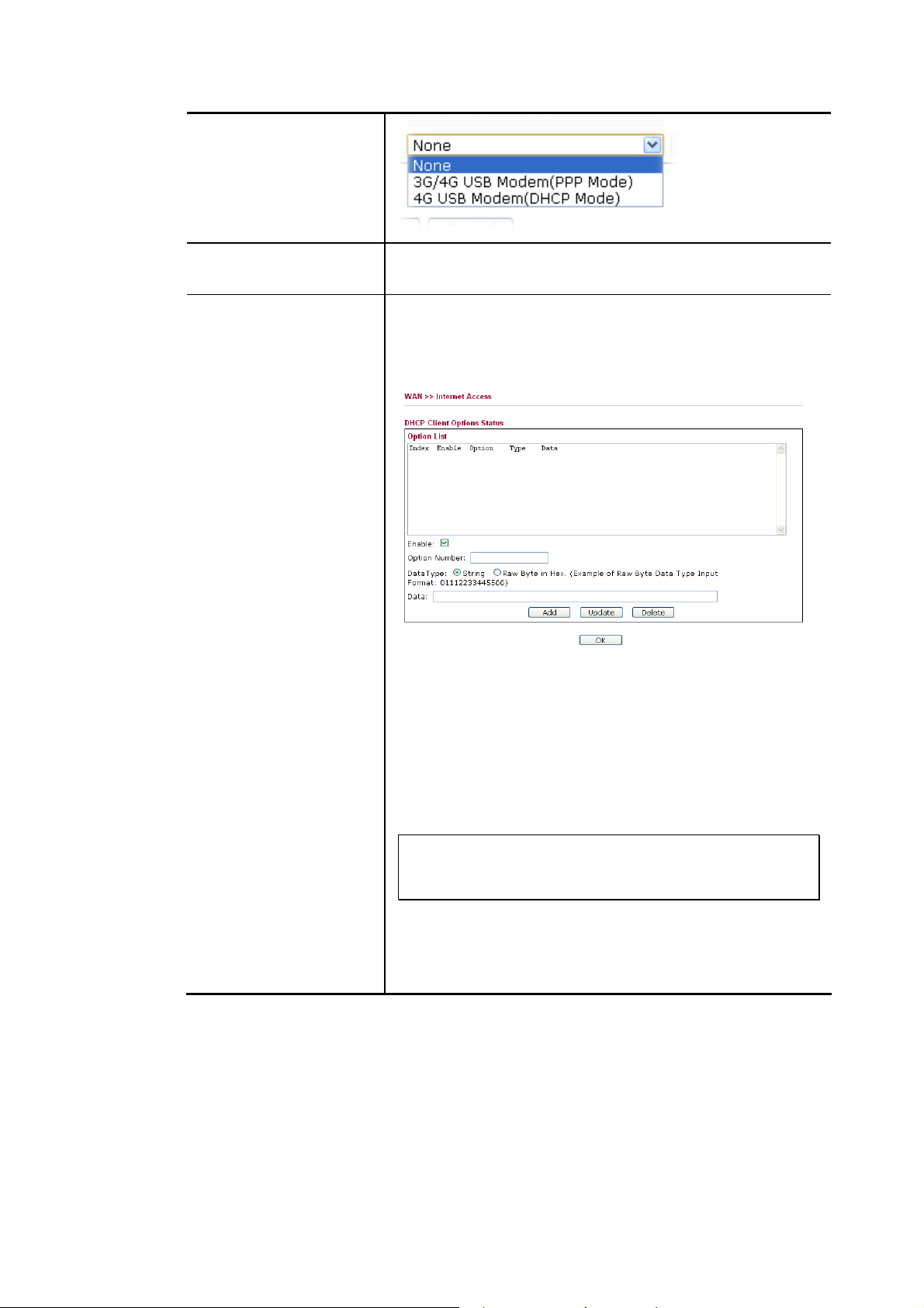
Use the drop down list to choose a proper access mode. The
details page of that mode will be popped up. If not, click
Details Page for accessing the page to configure the settings.
for WAN1
41
Page 50
for WAN2
Details Page
Advanced
This button will open different web page according to the
access mode that you choose in WAN interface.
This button allows you to configure DHCP client options.
DHCP packets can be processed by adding option number and
data information when such function is enabled and
configured.
Enable – Enable the function of DHCP Option. Each DHCP
option is composed by an option number with data. For
example,
Option number:100
Data: abcd
When such function is enabled, the specified values for DHCP
option will be seen in DHCP reply packets.
Option Number – Type a number for such function.
Note: If you choose to configure option 61 here, the
detailed settings in WAN>>Internet Access will be
overwritten.
DataType – Choose the type (ASCII or Hex) for the data to
be stored.
Data – Type the content of the data to be processed by the
function of DHCP option.
42
VigorFly 210 Series User’s Guide
Page 51

SSttaattiicc oorr DDyynnaammiicc IIPP ffoorr WWAANN11
For static IP mode, you usually receive a fixed public IP address or a public subnet, namely
multiple public IP addresses from your DSL or Cable ISP service providers. In most cases, a
Cable service provider will offer a fixed public IP, while a DSL service provider will offer a
public subnet. If you have a public subnet, you could assign an IP address or many IP address
to the WAN interface.
Dynamic IP allows a user to obtain an IP address automatically from a DHCP server on the
Internet.
To use Static IP or Dynamic IP as the accessing protocol of the internet, please choose Static
or Dynamic IP mode from Access drop down menu. Then click Detail Page to open the
following web page.
Available parameters are listed below:
Item Description
Obtain an IP address
automatically
Specify an IP Address
DNS Server IP Address
VigorFly 210 Series User’s Guide
To get an IP address from DHCP server, simply click this
button. The default router name will be displayed. Modify the
name if required.
Click this radio button to specify some data if you want to use
Static IP mode.
IP Address: Type the IP address.
Subnet Mask: Type the subnet mask.
Gateway IP Address: Type the gateway IP address.
Primary DNS Server - You must specify a DNS server IP
43
Page 52

Item Description
address here because your ISP should provide you with
usually more than one DNS Server. If your ISP does not
provide it, the router will automatically apply default DNS
Server IP address: 198.95.1.1 to this field.
Secondary DNS Server - You can specify secondary DNS
server IP address here because your ISP often provides you
more than one DNS Server. If your ISP does not provide it,
the router will automatically apply default secondary DNS
Server IP address.
Keep WAN Connection
MTU
WAN Connection
Detection
WAN Physical Type
Normally, this function is designed for Dynamic IP
environments because some ISPs will drop connections if
there is no traffic within certain periods of time. Check
Enable PING to keep alive box to activate this function.
PING to the IP - If you enable the PING function, please
specify the IP address for the system to PING it for keeping
alive.
PING Interval - Enter the interval for the system to execute
the PING operation.
It means Max Transmit Unit for packet. The default
setting is 1442.
Such function allows you to verify whether network
connection is alive or not through ARP Detect or Ping Detect.
Mode – Choose ARP Detect or Ping Detect for the system to
execute for WAN detection.
Ping IP – If you choose Ping Detect as detection mode, you
have to type IP address in this field for pinging.
TTL (Time to Live) – Displays value for your reference.
TTL value is set by telnet command.
Specify the data transmitting rate for such mode.
MAC Address Clone
MAC Address Clone is available when the box of Enable is
checked. The router will detect the MAC address
automatically. The result will be displayed in the field of
MAC Address.
After finishing all the settings here, please click OK to activate them.
44
VigorFly 210 Series User’s Guide
Page 53

PPPPPPooEE ffoorr WWAANN11
To choose PPPoE as the accessing protocol of the internet, please select PPPoE from the
Internet Access menu. The following web page will be shown.
Available parameters are listed below:
Item Description
ISP Access Setup
Username - Type in the username provided by ISP in this
field.
Password - Type in the password provided by ISP in this
field.
Confirm Password - Re-enter the password for
confirmation.
Service Name - Enter the description of the specific network
service.
PPP/MP Setup
Redial Policy - If you want to connect to Internet all the
time, you can choose Always On. Otherwise, choose
Connect on Demand.
Idle Time - Set the timeout for breaking down the Internet
after passing through the time without any action. When you
choose Connect on Demand, you have to type value here.
IPTV WAN
VigorFly 210 Series User’s Guide
VigorFly 210 supports IPTV application (traditional
television channel, movie or VoD service) through the
second WAN IP under PPPoE connection mode.
Mode - Choose DHCP or Static IP.
45
Page 54

Item Description
IP Address - Type the IP address if Static IP is selected as
the Mode for IPTV WAN application.
Subnet Mask - Type the subnet mask if Static IP is selected
as the Mode for IPTV WAN application.
MTU
WAN Connection
Detection
WAN Physical Type
MAC Address Clone
It means Max Transmit Unit for packet. The default
setting is 1442.
Such function allows you to verify whether network
connection is alive or not through Ping Detect.
Mode – Choose None or Ping Detect for the system to
execute for WAN detection.
Ping IP – If you choose Ping Detect as detection mode, you
have to type IP address in this field for pinging.
TTL (Time to Live) – Displays value for your reference.
TTL value is set by telnet command.
Specify the data transmitting rate for such mode.
MAC Address Clone is available when the box of Enable is
checked. The router will detect the MAC address
automatically. The result will be displayed in the field of
MAC Address.
After finishing all the settings here, please click OK to activate them.
46
VigorFly 210 Series User’s Guide
Page 55
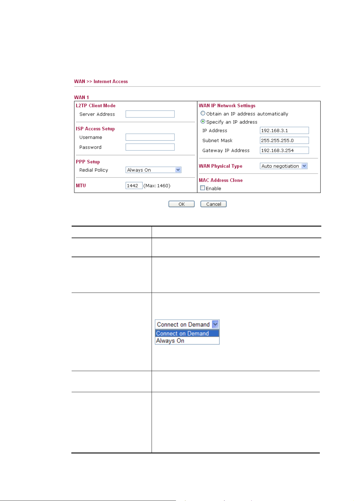
PPPPTTPP//LL22TTPP ffoorr WWAANN11
To use PPTP/L2TP as the accessing protocol of the internet, please choose PPTP/L2TP from
Connection Type drop down menu. The following web page will be shown.
Available parameters are listed below:
Item Description
L2TP Client Mode /
Server IP - Type in the IP address of the PPTP/L2TP server.
PPTP Client Mode
ISP Access Setup
User Name - Type in the username provided by ISP in this
field.
Password - Type in the password provided by ISP in this
field.
PPP Setup
Redial Policy - If you want to connect to Internet all the
time, you can choose Always On. Otherwise, choose
Connect on Demand.
Idle Time - Set the timeout for breaking down the Internet
after passing through the time without any action. When you
choose Connect on Demand, you have to type value here.
MTU
It means Max Transmit Unit for packet. The default
setting is 1442.
WAN IP Network
Settings
Obtain an IP address automatically – Click this button to
obtain the IP address automatically.
Specify an IP address – Click this radio button to specify
some data.
VigorFly 210 Series User’s Guide
IP Address – Type the IP address.
Subnet Mask – Type the subnet mask.
47
Page 56

Item Description
Default Gateway - Type the gateway address for this router.
WAN Physical Type
MAC Address Clone
Specify the data transmitting rate for such mode.
MAC Address Clone is available when the box of Enable is
checked. The router will detect the MAC address
automatically. The result will be displayed in the field of
MAC Address.
After finishing all the settings here, please click OK to activate them.
33GG//44GG UUSSBB MMooddeemm ((PPPPPP MMooddeemm)) ffoorr WWAANN11
If your router connects to a 3G/4G modem and you want to access Internet via 3G/4G modem,
choose 3G/4G as connection type and type the required information in this web page.
Available parameters are listed below:
Item Description
3G USB Modem 3G Always On –
SIM PIN code - Type PIN code of the SIM card that will be
used to access Internet.
Modem Initial String1/2 - Such value is used to initialize
USB modem. Please use the default value. If you have any
48
VigorFly 210 Series User’s Guide
Page 57

question, please contact to your ISP.
APN Name - APN means Access Point Name which is
provided and required by some ISPs.
Modem Dial String - Such value is used to dial through USB
mode. Please use the default value. If you have any question,
please contact to your ISP.
PPP Username - Type the PPP username (optional).
PPP Password - Type the PPP password (optional).
PPP Authentication - Select PAP only or PAP or CHAP
for PPP.
MTU
It means Max Transmit Unit for packet. The default
setting is 1442.
MAC Address Clone
After finishing all the settings here, please click OK to activate them.
44GG UUSSBB MMooddeemm ((DDHHCCPP MMooddee)) ffoorr WWAANN11
If your router connects to a 4G modem and you want to access Internet via 4G modem, choose
4G as connection type and type the required information in this web page.
MAC Address Clone is available when the box of Enable is
checked. The router will detect the MAC address
automatically. The result will be displayed in the field of
MAC Address.
VigorFly 210 Series User’s Guide
49
Page 58
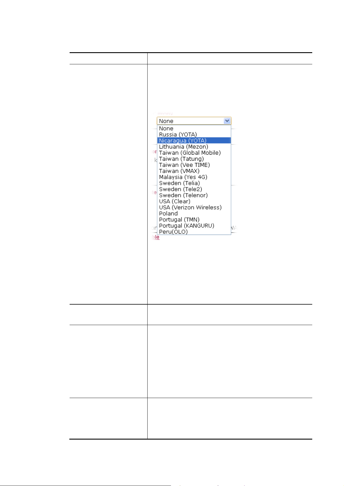
Available parameters are listed below:
Item Description
4G USB Modem
Service Provider – Choose the local service provider which
can serve network service according to the nature of USB
Modem (LTE/WiMAX) installed. For example, you live in
Taiwan and have a WiMAX modem inserted onto VigorFly
210. You can choose Taiwan (Global Mobile) to configure
necessary settings and then surf the Internet easily.
MTU
Keep WAN Connection
WAN Connection
Detection
Username - Type the user name acquired from the service
provider. Such item is required for WiMAX USB Modem.
Password - Type the password acquired from the service
provider. Such item is required for WiMAX USB Modem.
Cipher Suite –There are two encryption methods offered for
you to choose as cipher suite. Keep the default setting will be
better. Such item is required for WiMAX USB Modem.
It means Max Transmit Unit for packet. The default
setting is 1360.
Normally, this function is designed for Dynamic IP
environments because some ISPs will drop connections if
there is no traffic within certain periods of time. Check
Enable PING to keep alive box to activate this function.
PING to the IP - If you enable the PING function, please
specify the IP address for the system to PING it for keeping
alive.
PING Interval - Enter the interval for the system to execute
the PING operation.
Such function allows you to verify whether network
connection is alive or not through Ping Detect.
Mode – Choose None or Ping Detect for the system to
execute for WAN detection.
Ping IP – If you choose Ping Detect as detection mode, you
50
VigorFly 210 Series User’s Guide
Page 59

Item Description
have to type IP address in this field for pinging.
TTL (Time to Live) – Displays value for your reference.
TTL value is set by telnet command.
After finishing all the settings here, please click OK to activate them.
33GG//44GG UUSSBB MMooddeemm ((PPPPPP MMooddee)) ffoorr WWAANN22
WAN2 is used for backup only. Therefore, it is an optional setting. The default is None for
Access Mode. If it is required, choose 3G USB Modem or 4G USB Modem as a backup WAN
interface to access into Internet.
If you want to enable 3G/4G USB Modem in WAN2, make sure your WAN1 connection type
is not in 3G/4G mode. When the WAN1 connection is broken, the router will try to keep the
connection with 3G mode. After WAN1 connection is recovered, router will disconnect the
3G/3G connection automatically.
Below shows the configuration page for 3G/4G USB Modem:
Available parameters are listed below:
Item Description
3G USB Modem
VigorFly 210 Series User’s Guide
SIM PIN code - Type PIN code of the SIM card that will be
used to access Internet.
Modem Initial String1/2 - Such value is used to initialize
USB modem. Please use the default value. If you have any
question, please contact to your ISP.
APN Name - APN means Access Point Name which is
provided and required by some ISPs.
Modem Dial String - Such value is used to dial through USB
mode. Please use the default value. If you have any question,
please contact to your ISP.
51
Page 60

PPP Username - Type the PPP username (optional).
PPP Password - Type the PPP password (optional).
PPP Authentication - Select PAP only or PAP or CHAP
for PPP.
MTU
It means Max Transmit Unit for packet. The default setting is
1442.
SMS for WAN backup
Use the drop down list to choose one of the SMS profiles
(created in Application>>SMS) which will take effect when
WAN2 is up.
After finishing all the settings here, please click OK to activate them.
44GG UUSSBB MMooddeemm ((DDHHCCPP MMooddee)) ffoorr WWAANN22
Below shows the configuration page for 4G USB Modem:
Available parameters are listed below:
Item Description
4G USB Modem
Service Provider –Choose the local service provider which
can serve network service according to the nature of USB
Modem (LTE/WiMAX) installed. For example, you live in
Taiwan and have a WiMAX modem inserted onto VigorFly
210. You can choose Taiwan (Global Mobile) to configure
necessary settings and then surf the Internet easily.
52
VigorFly 210 Series User’s Guide
Page 61

The available settings will be different based on the service
provider specified. In this case, Taiwan (Global Mobile) is
chosen as an example.
Username
Type the user name acquired from the service provider. Such
item is required for WiMAX USB Modem.
Password
Type the password acquired from the service provider. Such
item is required for WiMAX USB Modem.
Cipher Suite
Cipher Suite –There are two encryption methods offered for
you to choose as cipher suite. Keep the default setting will be
better. Such item is required for WiMAX USB Modem.
MTU
It means Max Transmit Unit for packet. The default
setting is 1360.
SMS for WAN backup
After finishing all the settings here, please click OK to activate them.
Use the drop down list to choose one of the SMS profiles
(created in Application>>SMS) which will take effect when
WAN2 is up.
VigorFly 210 Series User’s Guide
53
Page 62

33..11..22 MMuullttii--VVLLAANN
This router allows you to create multi-VLAN for different purposes of data transferring.
Simply go to WAN and select Multi-VLAN.
GGeenneerraall
The system allows you to set up to eight channels for multi-VLAN.
Available settings are explained as follows:
Item Description
Enable Multi-VLAN
Setup
Management WAN
VLAN Setting
Channel
Enable
Check this box to activate such setting.
Enable Management WAN Setup- Check the box to enable
Management WAN configuration.
Management WAN VLAN ID - Data sent out through the
WAN port will be tagged with VLAN ID number specified
here. The range of ID number you can type is from 0 - 4095.
Management WAN Setting – Click this link to open
Management WAN setting.
Display the number of each channel.
Check this box to enable that channel. The channels that you
enabled here will be shown in the Multi-VLAN channel drop down list on the web page of Internet Access. Though you can
54
VigorFly 210 Series User’s Guide
Page 63

enable eight channels in this page, yet only one channel can be
chosen on the web page of Internet Access.
Add Tag
To identify the usage of VLAN, check this box to invoke this
setting. And type the number for VLAN ID (number).
Priority
It is used to set the priority for the audio and/or video data
transmission.
The adjustable range is from 0 (lowest) to 7 (highest).
After finishing all the settings here, please click OK to save the configuration.
VigorFly 210 Series User’s Guide
55
Page 64
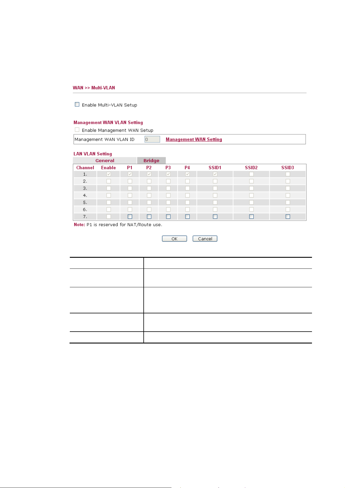
BBrriiddggee
General page lets you set general channel for multi-VLAN. This page allows you to configure
VLAN settings under Bridge mode. Simply click the Bridge tab to open Bridge configuration
page.
Available settings are explained as follows:
Item Description
Enable Multi-VLAN
Check this box to activate such setting.
Setup
Enable
Check this box to enable that channel. Only channel 3 to 8 can
be set in this page, for channel 1 to 2 are reserved for NAT
using.
P1 to P4
It means the LAN port 1 to 4. Check the box to designate the
LAN port for channel 2 to 7.
SSID1 to SSID3
Check the box to designate the SSID for channel 2 to 7.
When you finish the configuration, please click OK to save and exit this page.
56
VigorFly 210 Series User’s Guide
Page 65

33..22 LLAANN
Local Area Network (LAN) is a group of subnets regulated and ruled by router. The design of
network structure is related to what type of public IP addresses coming from your ISP.
BBaassiiccss ooff LLAANN
The most generic function of Vigor router is NAT. It creates a private subnet of your own. As
mentioned previously, the router will talk to other public hosts on the Internet by using public
IP address and talking to local hosts by using its private IP address. What NAT does is to
translate the packets from public IP address to private IP address to forward the right packets
to the right host and vice versa. Besides, Vigor router has a built-in DHCP server that assigns
private IP address to each local host. See the following diagram for a briefly understanding.
In some special case, you may have a public IP subnet from your ISP such as
220.135.240.0/24. This means that you can set up a public subnet or call second subnet that
each host is equipped with a public IP address. As a part of the public subnet, the Vigor router
will serve for IP routing to help hosts in the public subnet to communicate with other public
hosts or servers outside. Therefore, the router should be set as the gateway for public hosts.
VigorFly 210 Series User’s Guide
57
Page 66
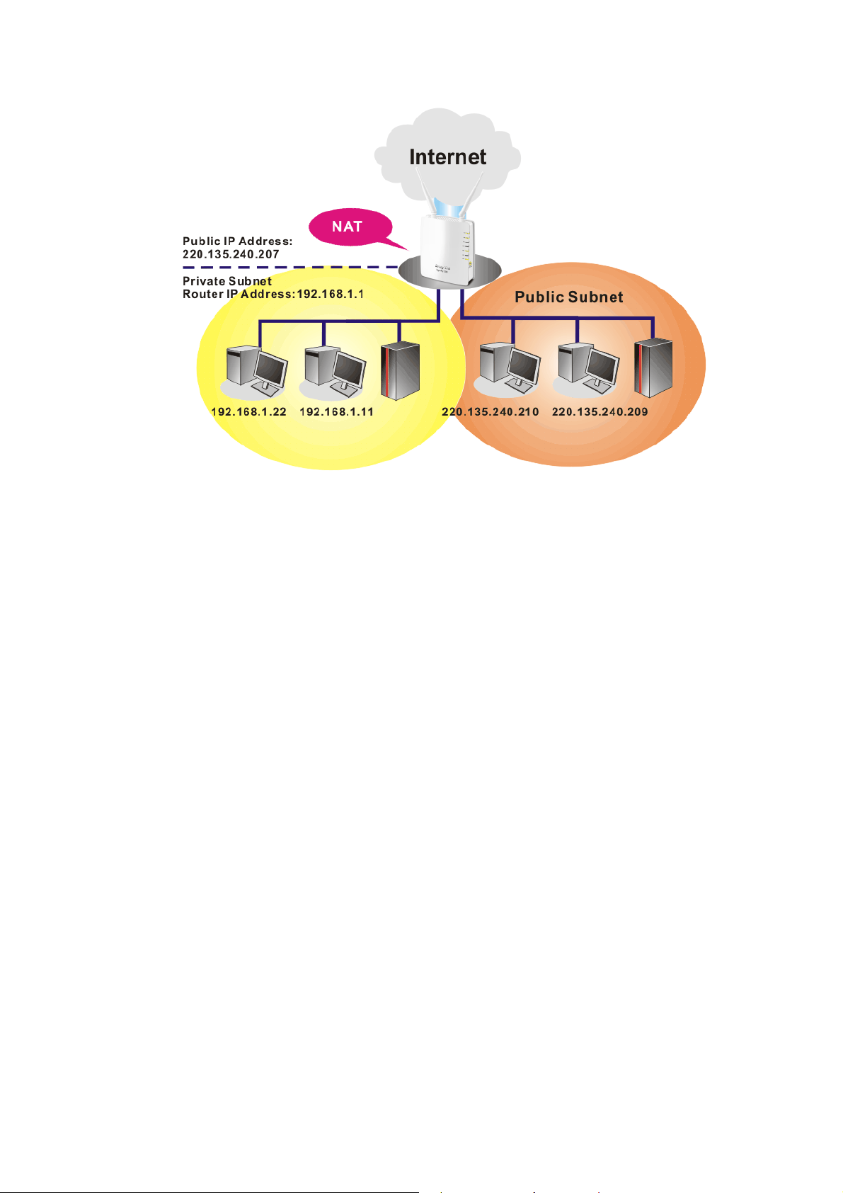
WWhhaatt iiss RRoouuttiinngg IInnffoorrmmaattiioonn PPrroottooccooll ((RRIIPP))
Vigor router will exchange routing information with neighboring routers using the RIP to
accomplish IP routing. This allows users to change the information of the router such as IP
address and the routers will automatically inform for each other.
WWhhaatt iiss SSttaattiicc RRoouuttee
When you have several subnets in your LAN, sometimes a more effective and quicker way for
connection is the Static routes function rather than other method. You may simply set rules to
forward data from one specified subnet to another specified subnet without the presence of
RIP.
58
VigorFly 210 Series User’s Guide
Page 67
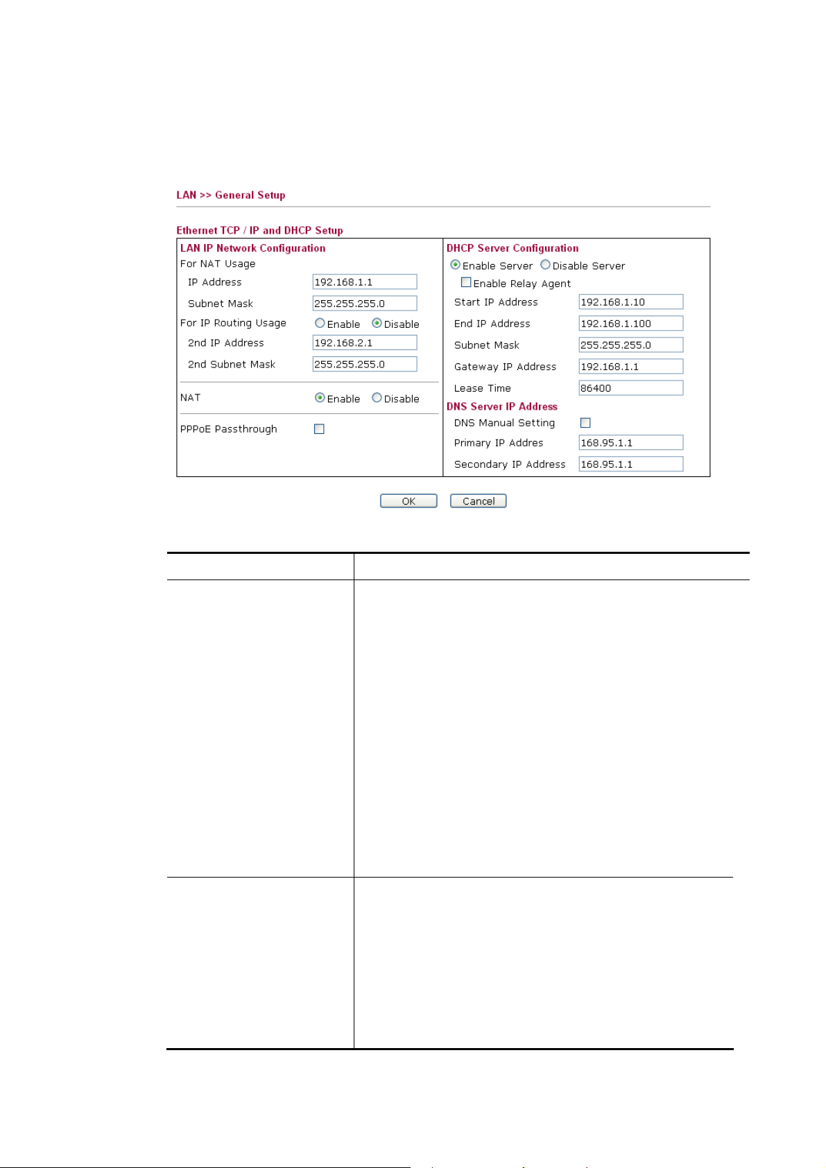
33..22..11 GGeenneerraall SSeettuupp
This page provides you the general settings for LAN. Click LAN to open the LAN settings page and choose General Setup.
Available settings are explained as follows:
Item Description
LAN IP Network
Configuration
IP Addr ess - Type in private IP address for connecting to a
local private network (Default: 192.168.1.1).
Subnet Mask- Type in an address code that determines the
size of the network. (Default: 255.255.255.0)
For IP Routing Usage - Click Enable to invoke this
function. The default setting is Disable.
nd
2
IP Address - Type in secondary IP address for
connecting to a subnet. (Default: 192.168.2.1)
nd
2
Subnet Mask - An address code that determines the
size of the network.
NAT – Check the box to execute the function of NAT in
LAN.
PPPoE Passthrough If you want to use PPPoE server in
the network via Vigor router, please check this box to
redirect the PPPoE frames to the specified location.
DHCP Server
Configuration
DHCP stands for Dynamic Host Configuration Protocol.
The router by factory default acts a DHCP server for your
network so it automatically dispatch related IP settings to
any local user configured as a DHCP client. It is highly
recommended that you leave the router enabled as a DHCP
server if you do not have a DHCP server for your network.
Enable Server- Let the router assign IP address to every
host in the LAN.
Disable Server- Let you manually assign IP address to
VigorFly 210 Series User’s Guide
59
Page 68

Item Description
every host in the LAN.
Start IP Address - Enter a value of the IP address pool for
the DHCP server to start with when issuing IP addresses. If
the 1st IP address of your router is 192.168.1.1, the starting
IP address must be 192.168.1.2 or greater, but smaller than
192.168.1.254.
End IP Address - Enter a value of the IP address pool for
the DHCP server to end with when issuing IP addresses.
Subnet Mask - Type in an address code that determines
the size of the network. (Default: 255.255.255.0/ 24)
Default Gateway - Enter a value of the gateway IP address
for the DHCP server. The value is usually as same as the
1st IP address of the router, which means the router is the
default gateway.
Lease Time - It allows you to set the leased time for the
specified PC.
DNS Server IP Address
DNS Manual Setting - If this function is enabled, LAN
PCs use Primary DNS Server and Secondary DNS Server
as their DNS servers. Otherwise, LAN PCs use the router
as their DNS server and the router will do DNS proxy for
them.
Primary DNS Address - You must specify a DNS server
IP address here because your ISP should provide you with
usually more than one DNS Server. If your ISP does not
provide it, the router will automatically apply default DNS
Server IP address: 194.109.6.66 to this field.
Secondary DNS Address - You can specify secondary
DNS server IP address here because your ISP often
provides you more than one DNS Server. If your ISP does
not provide it, the router will automatically apply default
secondary DNS Server IP address: 194.98.0.1 to this field.
If both the Primary IP and Secondary IP Address fields are
left empty, the router will assign its own IP address to local
users as a DNS proxy server and maintain a DNS cache.
If the IP address of a domain name is already in the DNS
cache, the router will resolve the domain name
immediately. Otherwise, the router forwards the DNS
query packet to the external DNS server by establishing a
WAN (e.g. DSL/Cable) connection.
After finishing all the settings here, please click OK to activate them.
60
VigorFly 210 Series User’s Guide
Page 69

33..22..22 SSttaattiicc RRoouuttee
Go to LAN to open setting page and choose Static Route. It can help to describe one way of configuring path selection of router in computer network.
Available settings are explained as follows:
Item Description
Add a routing rule
Destination - Type the IP address for the routing rule applied
to.
Range - Choose Host or Net for specifying gateway or
netmask setting of such routing rule.
Netmask - Type the netmask for such routing rule if you
choose Net as Range setting.
Gateway - Type the gateway address for such routing rule.
Interface - Choose WAN or LAN as the interface for such
route.
Comment - Type words as notification for such routing.
After finishing all the settings here, please click OK to activate them.
VigorFly 210 Series User’s Guide
61
Page 70
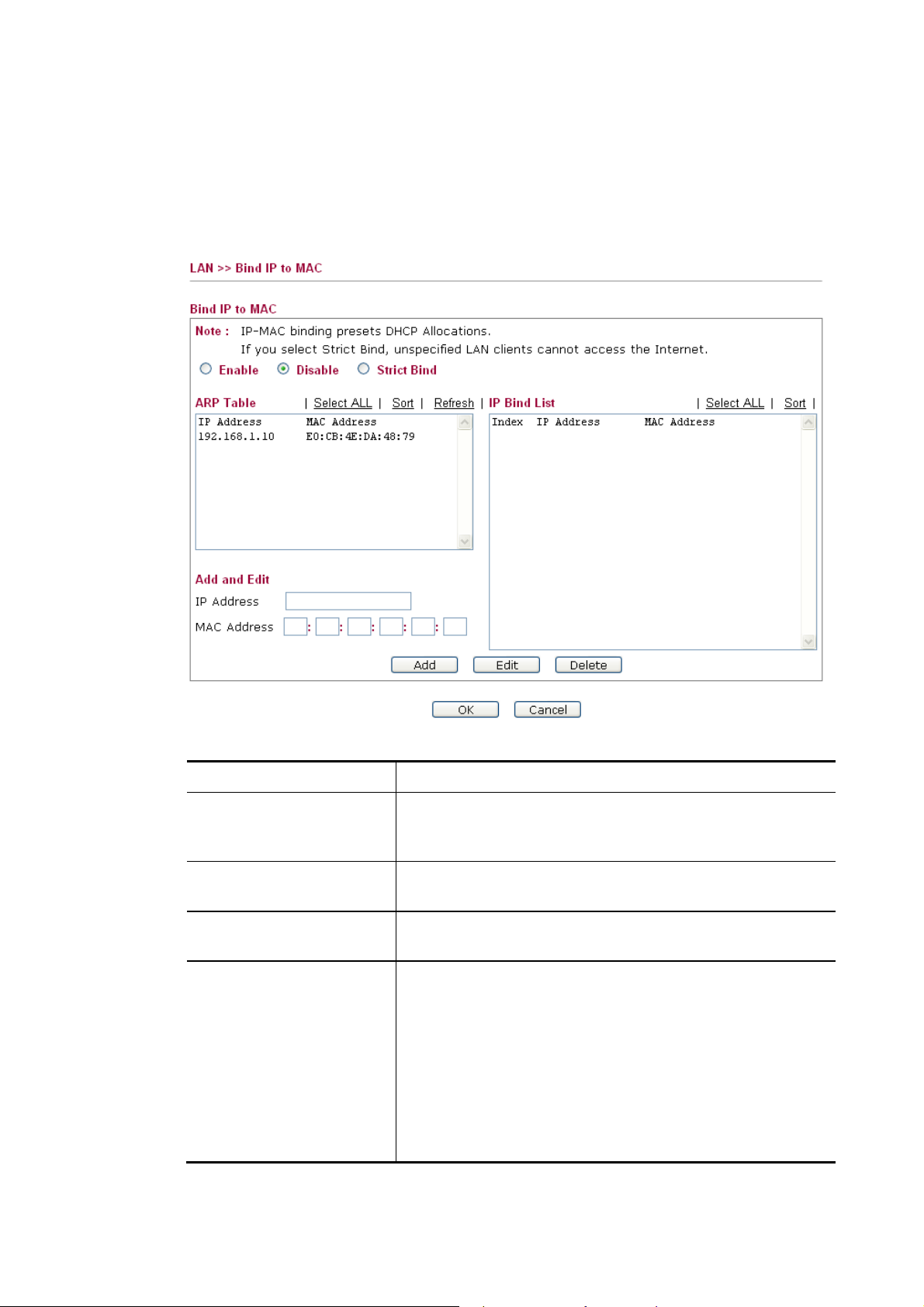
33..22..33 BBiinndd IIPP ttoo MMAACC
This function is used to bind the IP and MAC address in LAN to have a strengthening control
in network. When this function is enabled, all the assigned IP and MAC address binding
together cannot be changed. If you modified the binding IP or MAC address, it might cause
you not access into the Internet.
Click LAN and click Bind IP to MAC to open the setup page.
Available settings are explained as follows:
Item Description
Enable
Click this radio button to invoke this function. However,
IP/MAC which is not listed in IP Bind List also can connect
to Internet.
Disable
Click this radio button to disable this function. All the
settings on this page will be invalid.
Strict Bind
Click this radio button to block the connection of the
IP/MAC which is not listed in IP Bind List.
ARP Table
This table is the LAN ARP table of this router. The
information for IP and MAC will be displayed in this field.
Each pair of IP and MAC address listed in ARP table can be
selected and added to IP Bind List by clicking Add below
Select All - Click this link to select all the items in the ARP
table.
Sort - Reorder the table based on the IP address.
Refresh - Refresh the ARP table listed below to obtain the
newest ARP table information.
.
62
VigorFly 210 Series User’s Guide
Page 71

33..33 NNAATT
Add or Update
IP Bind List
After finishing all the settings here, please click OK to save the configuration.
Note: Before you select Strict Bind, you have to bind one set of IP/MAC address for one
PC. If not, no one of the PCs can access into Internet. And the web user interface of the
router might not be accessed.
IP Address – Type the IP address that will be used for the
specified MAC address.
Mac Address – Type the MAC address that is used to bind
with the assigned IP address.
It displays a list for the IP bind to MAC information.
Add - It allows you to add the one you choose from the ARP
table or the IP/MAC address typed in Add and Edit to the
table of IP Bind List.
Update - It allows you to edit and modify the selected IP
address and MAC address that you create before.
Delete - You can remove any item listed in IP Bind List.
Simply click and select the one, and click Delete. The
selected item will be removed from the IP Bind List.
Usually, the router serves as an NAT (Network Address Translation) router. NAT is a
mechanism that one or more private IP addresses can be mapped into a single public one.
Public IP address is usually assigned by your ISP, for which you may get charged. Private IP
addresses are recognized only among internal hosts.
When the outgoing packets destined to some public server on the Internet reach the NAT
router, the router will change its source address into the public IP address of the router, select
the available public port, and then forward it. At the same time, the router shall list an entry in
a table to memorize this address/port-mapping relationship. When the public server response,
the incoming traffic, of course, is destined to the router’s public IP address and the router will
do the inversion based on its table. Therefore, the internal host can communicate with external
host smoothly.
The benefit of the NAT includes:
Save cost on applying public IP address and apply efficient usage of IP address.
NAT allows the internal IP addresses of local hosts to be translated into one public IP
address, thus you can have only one IP address on behalf of the entire internal hosts.
Enhance security of the internal network by obscuring the IP address. There are
many attacks aiming victims based on the IP address. Since the attacker cannot be aware
of any private IP addresses, the NAT function can protect the internal network.
On NAT page, you will see the private IP address defined in RFC-1918. Usually we use the
192.168.1.0/24 subnet for the router. As stated before, the NAT facility can map one or
more IP addresses and/or service ports into different specified services. In other words, the
NAT function can be achieved by using port mapping methods.
Below shows the menu items for NAT.
VigorFly 210 Series User’s Guide
63
Page 72
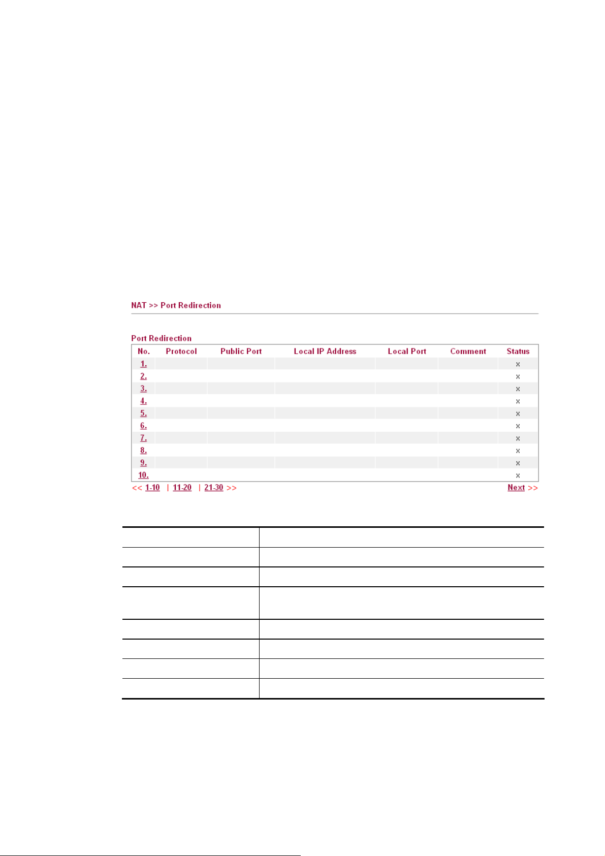
33..33..11 PPoorrtt RReeddiirreeccttiioonn
Port Redirection is usually set up for server related service inside the local network (LAN), such as web servers, FTP servers, E-mail servers etc. Most of the case, you need a public IP address for each server and this public IP address/domain name are recognized by all users. Since the server is actually located inside the LAN, the network well protected by NAT of the router, and identified by its private IP address/port, the goal of Port Redirection function is to forward all access request with public IP address from external users to the mapping private IP address/port of the server.
Note that the port redirection can only apply to incoming traffic.
Open Port allows you to open a range of ports for the traffic of special applications. Common
application of Open Port includes P2P application (e.g., BT, KaZaA, Gnutella, WinMX,
eMule and others), Internet Camera etc. Ensure that you keep the application involved
up-to-date to avoid falling victim to any security exploits.
To use Port Redirection, please go to NAT page and choose Port Redirection web page. The
Port Redirection Table provides 30 port-mapping entries for the internal hosts.
Each item is explained as follows:
Item Description
No
Protocol
Public Port
Display the number of the profile.
Display the description of the specific network service.
Display the port number which will be redirected to the
specified Private IP and Port of the internal host.
Local IP Address
Local Port
Comment
Status
Display the private IP address of the internal host.
Display the private port of the internal host.
Display the brief description for such profile.
Display if the profile is enabled (v) or not (x).
Press any number under Index to access into next page for configuring port redirection.
64
VigorFly 210 Series User’s Guide
Page 73

Available settings are explained as follows:
Item Description
Enable
Type
Check this box to enable such Port Redirection profile.
Specify the type for such profile. The type of Virtual server
offers several options with dedicated server and port number.
Packets passing through such port number will be redirected
into the local IP address and local port assigned below.
If User Define is selected, there are four sub-options offered
to choose.
If Virtual Server is selected, specify a server from the drop
down list.
VigorFly 210 Series User’s Guide
65
Page 74

Protocol
Select the transport layer protocol (TCP or UDP or
TCP+UDP).
Local IP Address
Specify the private IP address of the internal host providing
the service. I
Local Port
Specify the private port number of the service offered by the
internal host.
Comment
Type a brief description for such profile if required. The
Maximum length is 23–character long.
After finishing all the settings here, please click OK to save the configuration.
66
VigorFly 210 Series User’s Guide
Page 75
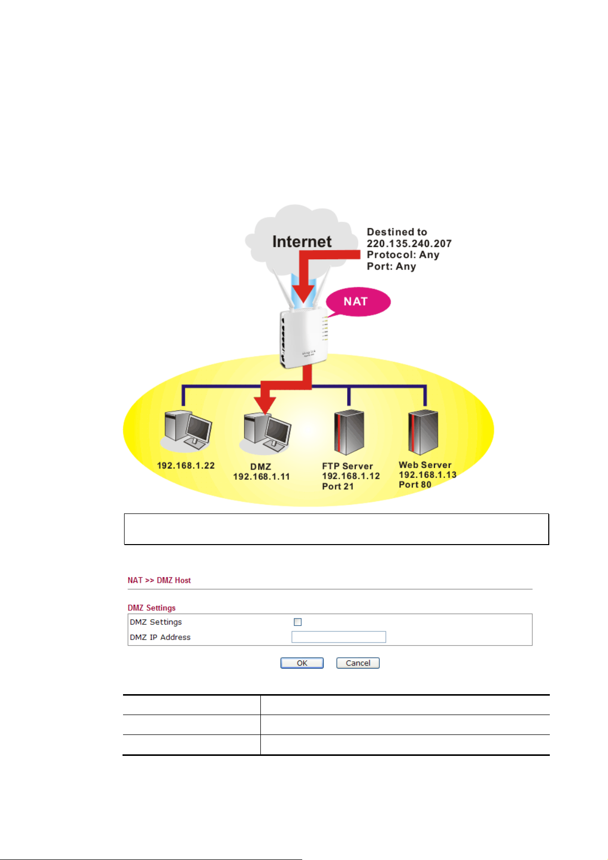
33..33..22 DDMMZZ HHoosstt
As mentioned above, Port Redirection can redirect incoming TCP/UDP or other traffic on
particular ports to the specific private IP address/port of host in the LAN. However, other IP
protocols, for example Protocols 50 (ESP) and 51 (AH), do not travel on a fixed port. Vigor
router provides a facility DMZ Host that maps ALL unsolicited data on any protocol to a
single host in the LAN. Regular web surfing and other such Internet activities from other
clients will continue to work without inappropriate interruption. DMZ Host allows a defined
internal user to be totally exposed to the Internet, which usually helps some special
applications such as Netmeeting or Internet Games etc.
Note: The security properties of NAT are somewhat bypassed if you set up DMZ host. We
suggest you to add additional filter rules or a secondary firewall.
Click DMZ Host to open the following page:
Available settings are explained as follows:
Item Description
DMZ Settings
DMZ IP Address
Check this box to enable the DMZ Host function.
Enter the private IP address of the DMZ host.
After finishing all the settings here, please click OK to save the configuration.
VigorFly 210 Series User’s Guide
67
Page 76

33..44 FFiirreewwaallll
BBaassiiccss ffoorr FFiirreewwaallll
While the broadband users demand more bandwidth for multimedia, interactive applications,
or distance learning, security has been always the most concerned. The firewall of the Vigor
router helps to protect your local network against attack from unauthorized outsiders. It also
restricts users in the local network from accessing the Internet. Furthermore, it can filter out
specific packets that trigger the router to build an unwanted outgoing connection.
DDeenniiaall ooff SSeerrvviiccee ((DDooSS)) DDeeffeennssee
The DoS Defense functionality helps you to detect and mitigate the DoS attack. The attacks
are usually categorized into two types, the flooding-type attacks and the vulnerability attacks.
The flooding-type attacks will attempt to exhaust all your system's resource while the
vulnerability attacks will try to paralyze the system by offending the vulnerabilities of the
protocol or operation system.
The DoS Defense function enables the Vigor router to inspect every incoming packet based on
the attack signature database. Any malicious packet that might duplicate itself to paralyze the
host in the secure LAN will be strictly blocked and a Syslog message will be sent as warning, if
you set up Syslog server.
Also the Vigor router monitors the traffic. Any abnormal traffic flow violating the pre-defined
parameter, such as the number of thresholds, is identified as an attack and the Vigor router will
activate its defense mechanism to mitigate in a real-time manner.
Below shows the menu items for Firewall.
68
VigorFly 210 Series User’s Guide
Page 77

33..44..11 DDooSS DDeeffeennssee
As a sub-functionality of IP Filter/Firewall, there are 5 types of detect/ defense function in the DoS Defense setup. The DoS Defense functionality is disabled for default.
Click Firewall and click DoS Defense to open the setup page.
Available settings are explained as follows:
Item Description
Enable Dos Defense
Check the box to activate the DoS Defense Functionality.
Enable SYN flood defense
Enable UDP flood defense
Enable ICMP flood
defense
Check the box to activate the SYN flood defense function.
Once detecting the Threshold of the TCP SYN packets from
the Internet has exceeded the defined value, the Vigor router
will start to randomly discard the subsequent TCP SYN
packets for a period defined in Timeout. The goal for this is
prevent the TCP SYN packets’ attempt to exhaust the
limited-resource of Vigor router. By default, the threshold
and timeout values are set to 50 packets per second and 10
seconds, respectively.
Check the box to activate the UDP flood defense function.
Once detecting the Threshold of the UDP packets from the
Internet has exceeded the defined value, the Vigor router will
start to randomly discard the subsequent UDP packets for a
period defined in Timeout. The default setting for threshold
and timeout are 1500 packets per second and 10 seconds,
respectively.
Check the box to activate the ICMP flood defense function.
Similar to the UDP flood defense function, once if the
Threshold of ICMP packets from Internet has exceeded the
defined value, the router will discard the ICMP echo requests
coming from the Internet. The default setting for threshold and
timeout are 50 packets per second and 10 seconds,
respectively.
Enable Furtive port
scanner detection
VigorFly 210 Series User’s Guide
Port Scan attacks the Vigor router by sending lots of packets
to many ports in an attempt to find ignorant services would
respond. Check the box to activate the Port Scan detection.
Whenever detecting this malicious exploration behavior, the
Vigor router will send out a warning.
69
Page 78

Enable Ping of Death
Defense
After finishing all the settings here, please click OK to save the configuration.
33..44..22 MMAACC//IIPP//PPoorrtt FFiilltteerriinngg
This page allows you to set up to 32 MAC/IP/Port Filtering rules. When you finish the
filtering rule, simply click OK. The new rule will be displayed below in this page.
Check the box to activate the Block Ping of Death function.
This attack involves the perpetrator sending overlapping
packets to the target hosts so that those target hosts will hang
once they re-construct the packets. The Vigor routers will
block any packets realizing this attacking activity.
Available parameters are listed below:
Item Description
Basic Settings
MAC/IP/Port Filtering - Choose Enable to activate
MAC/IP/Port Filtering function.
Default Policy –
Accepted: all the packets that do not match with any rule
will be accepted.
Dropped: all the packets that do not match with any rule
will be blocked.
MAC/IP/Port Filter
Settings
MAC Address - Type the MAC address for the router.
Dest IP Address - Type the destination IP address for
applying such rule.
Source IP Address - Type the source IP address for
applying such rule.
70
VigorFly 210 Series User’s Guide
Page 79

Protocol - Specify the protocol(s) which this filter rule will
apply to.
Dest Port Range - Determine the port range for the
destination.
Source Port Range - Determine the port range for the
source.
Action –
Accept: the packets that match with such rule will be
accepted.
Drop: the packets that match with such rule will be
blocked.
Comment - Enter filter set comments/description.
Maximum length is 23–character long.
Add
After finishing all the settings here, please click OK to save the configuration.
33..44..33 SSyysstteemm SSeeccuurriittyy
Stateful Packet Inspection (SPI) is a firewall architecture that works at the network layer.
Unlike legacy static packet filtering, which examines a packet based on the information in its
header, stateful inspection builds up a state machine to track each connection traversing all
interfaces of the firewall and makes sure they are valid. The stateful firewall of Vigor router
not just examine the header information also monitor the state of the connection.
The purpose of this is to enable the SPI firewall for the filtering incoming packets and
outgoing packets. Simply check the box and click OK.
After typing required information on above, click this
button to create a new filtering rule. The new rule will be
displayed on the bottom of this web page.
33..44..44 CCoonntteenntt FFiilltteerriinngg
WWeebb CCoonntteenntt FFiilltteerr
We all know that the content on the Internet just like other types of media may be
inappropriate sometimes. As a responsible parent or employer, you should protect those in your
trust against the hazards. With Web filtering service of the Vigor router, you can protect your
business from common primary threats, such as productivity, legal liability, network and
security threats. For parents, you can protect your children from viewing adult websites or chat
rooms.
VigorFly 210 Series User’s Guide
71
Page 80

Once you have activated your Web Filtering service in Vigor router and chosen the categories of
website you wish to restrict, each URL address requested (e.g.www.bbc.co.uk) will be checked
against our server database. This database is updated as frequent as daily by a global team of
Internet researchers. The server will look up the URL and return a category to your router. Your
Vigor router will then decide whether to allow access to this site according to the categories you
have selected. Please note that this action will not introduce any delay in your Web surfing
because each of multiple load balanced database servers can handle millions of requests for
categorization.
UURRLL CCoonntteenntt FFiilltteerr
To provide an appropriate cyberspace to users, Vigor router equips with URL Content Filter
not only to limit illegal traffic from/to the inappropriate web sites but also prohibit other web
feature where malicious code may conceal.
Once a user type in or click on an URL with objectionable keywords, URL keyword blocking
facility will decline the HTTP request to that web page thus can limit user’s access to the
website. You may imagine URL Content Filter as a well-trained convenience-store clerk who
won’t sell adult magazines to teenagers. At office, URL Content Filter can also provide a
job-related only environment hence to increase the employee work efficiency. How can URL
Content Filter work better than traditional firewall in the field of filtering? Because it checks
the URL strings or some of HTTP data hiding in the payload of TCP packets while legacy
firewall inspects packets based on the fields of TCP/IP headers only.
On the other hand, Vigor router can prevent user from accidentally downloading malicious
codes from web pages. It’s very common that malicious codes conceal in the executable objects,
such as ActiveX, Java Applet, compressed files, and other executable files. Once downloading
these types of files from websites, you may risk bringing threat to your system. For example, an
ActiveX control object is usually used for providing interactive web feature. If malicious code
hides inside, it may occupy user’s system.
Open Firewall>>Content Filtering to access into the following page.
Available parameters are listed below:
Item Description
Web Content Filter
At present, there are three content filters offered here for
72
VigorFly 210 Series User’s Guide
Page 81
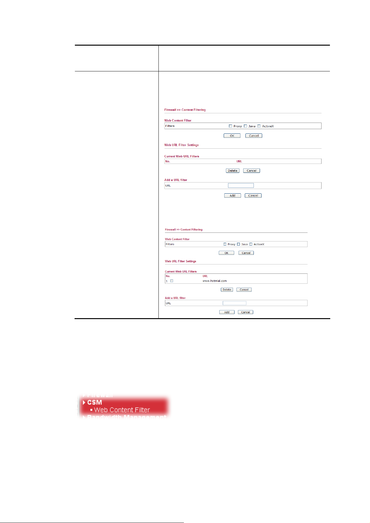
you to choose. Check Proxy, Java or ActiveX and click
OK. The system will filter and block the web pages
according to the item you specified here.
Web URL Filter Settings
URL – type the URL of the web site in the field of URL
and click Add. The new link with the URL you specified
will be shown on this page. The system will filter and block
the web pages according to the item you specified here.
To delete the URL setting, simply click that one and click
Delete to remove it.
After finishing all the settings here, please click OK to save the configuration.
33..55 CCSSMM
CCoonntteenntt SSeeccuurriittyy MMaannaaggeemmeenntt ((CCSSMM))
CSM is an abbreviation of Content Security Management which is used to filter the web content to reach a goal of security management.
33..55..11 WWeebb CCoonntteenntt FFiilltteerr
We all know that the content on the Internet just like other types of media may be
inappropriate sometimes. As a responsible parent or employer, you should protect those in your
trust against the hazards. With Web filtering service of the Vigor router, you can protect your
business from common primary threats, such as productivity, legal liability, network and
VigorFly 210 Series User’s Guide
73
Page 82

security threats. For parents, you can protect your children from viewing adult websites or chat
rooms.
Once you have activated your Web Filtering service in Vigor router and chosen the categories of
website you wish to restrict, each URL address requested (e.g.www.bbc.co.uk) will be checked
against our server database. This database is updated as frequent as daily by a global team of
Internet researchers. The server will look up the URL and return a category to your router. Your
Vigor router will then decide whether to allow access to this site according to the categories you
have selected. Please note that this action will not introduce any delay in your Web surfing
because each of multiple load balanced database servers can handle millions of requests for
categorization.
Note 1: Web Content Filter (WCF) is not a built-in service of Vigor router but a service
powered by Commtouch. If you want to use such service (trial or formal edition), you
have to perform the procedure of activation first. For the service of formal edition, please
contact with your dealer/distributor for detailed information.
Note 2: Commtouch is merged by Cyren, and GlobalView services will be continued to
deliver powerful cloud-based information security solutions! Refer to:
http://www.prnewswire.com/news-releases/commtouch-is-now-cyren-239025151.html
Click CSM>>Web Content Filter to open the following page:
Available parameters are listed below:
74
VigorFly 210 Series User’s Guide
Page 83

Item Description
Enable
Source IP/Mask
Filter Https
License Information
Activate
Misclassified Report
Check the box to enable WCF filtering function.
Type the IP address with mask address
(e.g.,192.168.1.0/255.255.255.0 to indicate a network or
type 192.168.1.10/255.255.255.255 to indicate a single IP)
to be filtered by WCF mechanism.
Check the box to enable HTTPS service.
Display the license information for current used.
If the WCF mechanism has been activated successfully, a
green light will be shown on the screen.
Click it to activate Commtouch WCF mechanism.
You can send a report for mistaken classified URL to
Commtouch by clicking such link.
HHooww ttoo aaccttiivvaattee wweebb ccoonntteenntt ffiilltteerr??
Before activating web content filter, register your Vigor router first. Refer to 2.6 Registering
Vigor Router for detailed information.
Then, follow the steps listed blow to activate WCF.
1. Click the Activate link from Web-Filter License to activate WCF service.
2. A Login page will be shown on the screen. Please type the account and password that you
created previously. And click Login.
VigorFly 210 Series User’s Guide
75
Page 84

3. From the Device’s Service section, click the Trial button for WCF service with provider
Commtouch.
Available parameters are listed below:
Item Description
Rename
Transfer
It allows you to change the account name.
It allows you to transfer the Vigor device together with
applied license to someone who has already
registered another account in myvigor.draytek.com. Be
sure to press this button to transfer the product to
whom you want to give. Otherwise he/she might not
be able to maintain the license hooked up to the Vigor
device.
Back
It allows you to return to the previous account.
76
VigorFly 210 Series User’s Guide
Page 85

4. In the following page, check the box of “I have read and accept the above Agreement”.
The system will find out the date for you to activate this version of service. Then, click
Next.
5. When this page appears, click Register.
6. Next, when the registration is completed. You will get the following screen.
7. Return to web configuration of VigorFly 210.
8. Refresh the page of CSM>>Web Content Filter.
VigorFly 210 Series User’s Guide
77
Page 86

A green circle appears next to the link of License Information. It means the WCF license
is valid.
33..66 BBaannddwwiiddtthh MMaannaaggeemmeenntt
Below shows the menu items for Bandwidth Management.
33..66..11 SSeessssiioonn LLiimmiitt
A PC with private IP address can access to the Internet via NAT router. The router will
generate the records of NAT sessions for such connection. The P2P (Peer to Peer) applications
(e.g., BitTorrent) always need many sessions for procession and also they will occupy over
resources which might result in important accesses impacted. To solve the problem, you can
use limit session to limit the session procession for specified Hosts.
78
VigorFly 210 Series User’s Guide
Page 87

Available settings are explained as follows:
Item Description
Session Limit
Enable – Check it to activate the function of limit session.
Default session limit - Defines the default session number
used for each computer in LAN.
Limitation List
Displays a list of specific limitations that you set on this
web page.
Specific Limitation
Start IP- Defines the start IP address for limit session.
End IP - Defines the end IP address for limit session.
Session Limit - Defines the available session number for
each host in the specific range of IP addresses. If you do not
set the session number in this field, the system will use the
default session limit for the specific limitation you set for
each index.
Add - Adds the specific session limitation onto the list
above.
Edit - Allows you to edit the settings for the selected
limitation.
Delete - Remove the selected settings existing on the
limitation list.
After finishing all the settings, please click OK to save the configuration.
VigorFly 210 Series User’s Guide
79
Page 88

33..66..22 BBaannddwwiiddtthh LLiimmiitt
The downstream or upstream from FTP, HTTP or some P2P applications will occupy large of
bandwidth and affect the applications for other programs. Please use Limit Bandwidth to make
the bandwidth usage more efficient.
Available settings are explained as follows:
Item Description
Bandwidth Limit
Enable – Check it to activate the function of limit
bandwidth.
Default TX limit - Define the default speed of the upstream
for each computer in LAN.
Default RX limit - Define the default speed of the
downstream for each computer in LAN.
Limitation List
Display a list of specific limitations that you set on this web
page.
Specific Limitation
Start IP - Define the start IP address for limit bandwidth.
End IP - Define the end IP address for limit bandwidth.
TX limit - Define the limitation for the speed of the
upstream. If you do not set the limit in this field, the system
will use the default speed for the specific limitation you set
for each index.
RX limit - Define the limitation for the speed of the
80
VigorFly 210 Series User’s Guide
Page 89
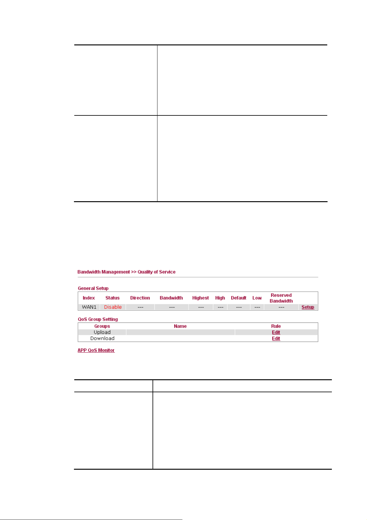
downstream. If you do not set the limit in this field, the
system will use the default speed for the specific limitation
you set for each index.
Add - Add the specific speed limitation onto the list above.
Edit - Allow you to edit the settings for the selected
limitation.
Delete - Remove the selected settings existing on the
limitation list.
Smart Bandwidth Limit
After finishing all the settings, please click OK to save the configuration.
33..66..33 QQuuaalliittyy ooff SSeerrvviiccee
Deploying QoS (Quality of Service) management to guarantee that all applications receive the
service levels required and sufficient bandwidth to meet performance expectations is indeed
one important aspect of modern enterprise network.
Enable - Check this box to have the bandwidth limit
determined by the system automatically.
TX limit - Define the limitation for the speed of the
upstream. If you do not set the limit in this field, the system
will use the default speed for the specific limitation you set
for each index.
RX limit - Define the limitation for the speed of the
downstream. If you do not set the limit in this field, the
system will use the default speed for the specific limitation
you set for each index.
Available settings are explained as follows:
Item Description
General Setup
VigorFly 210 Series User’s Guide
Index – Display the WAN interface number that you can edit.
Status – Display if the WAN interface is available for such
function or not.
Direction – Display which direction that such function will
influence.
Bandwidth – Display the inbound and outbound bandwidth
setting for the WAN interface.
Highest/High/Default/Low – Display the bandwidth
81
Page 90

Item Description
percentage for each class.
Reserved Bandwidth–Display the percentage of bandwidth
reserved for the router.
Setup – Allow to configure general QoS setting for WAN
interface.
QoS Group Setting
APP QoS Monitor
Group – Display the purpose (Upload / Download) of the
rule to be applied.
Name – Display the name(s) grouped for Upload / Download.
Rule – Allow to configure detailed settings for the selected
group. Click Edit to access into the detailed setting page.
Check the box of Enable Application QoS Monitor. The
system will monitor the application and display current status
on this page periodically.
82
VigorFly 210 Series User’s Guide
Page 91
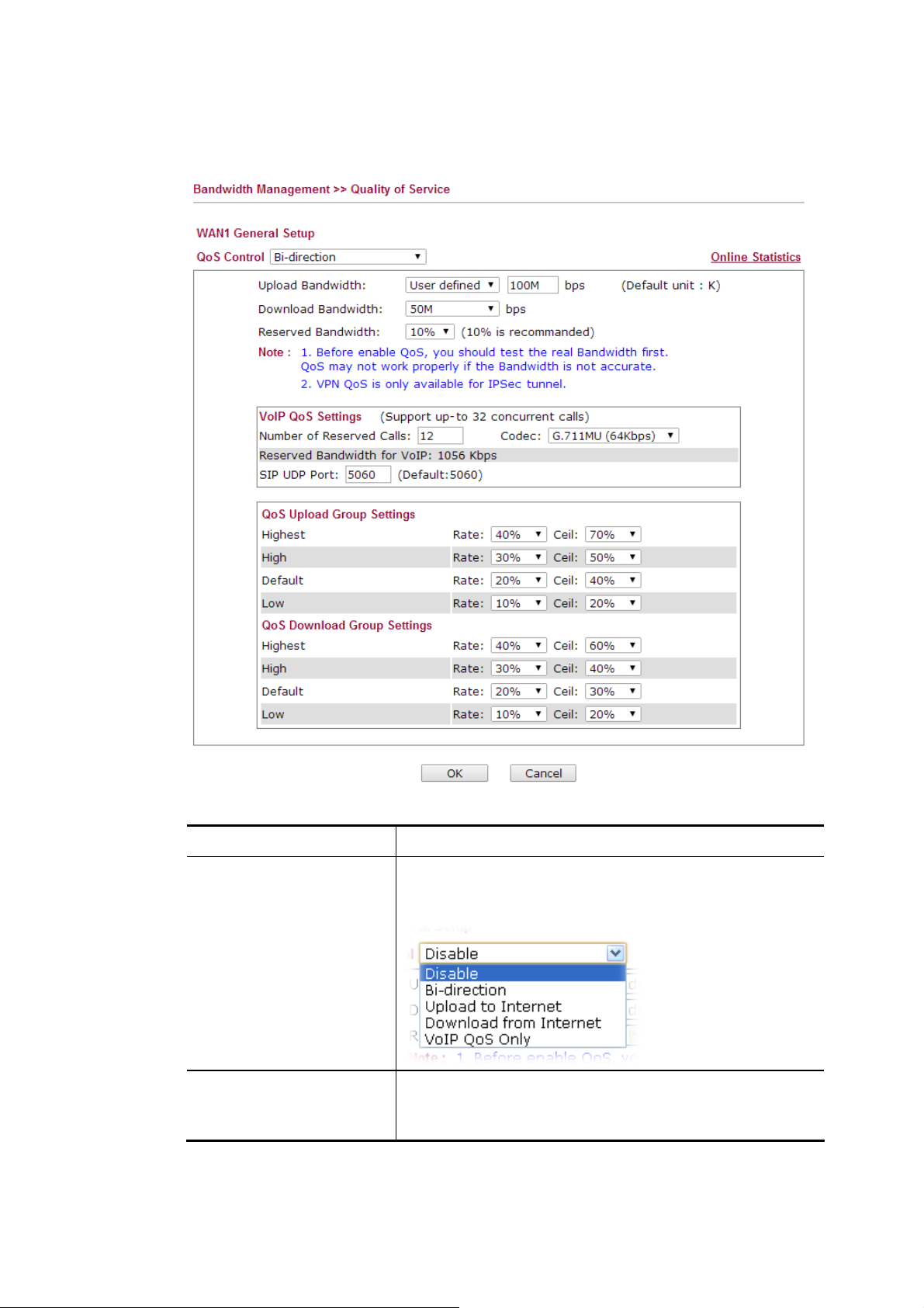
GGeenneerraall SSeettuupp ffoorr WWAANN IInntteerrffaaccee
When you click Setup, you can configure the bandwidth ratio for QoS of the WAN interface.
Available settings are explained as follows:
Item Description
QoS Control
There are four classes of QoS offered by Vigor router. Each
class contains different settings. Here we take Bi-direction
as an example. Related settings will be explained below.
Upload Bandwidth
It will be applied to outgoing traffic. Use the drop down list
to specify the bandwidth for data transmission. If you
choose User defined, you have to type the value manually.
VigorFly 210 Series User’s Guide
83
Page 92

Download Bandwidth
It will be applied to incoming traffic. Use the drop down list
to specify the bandwidth for data receiving. If you choose
User defined, you have to type the value manually.
Reserved Bandwidth
VoIP QoS Settings
QoS Upload Group
Settings
Such percentage of bandwidth is reserved for the usage of
the router only.
Number of Reserved Calls – Type the number of the VoIP
calls that QoS configuration would apply to.
Codec – Select one of five codecs as the default for your
VoIP calls. The codec used for each call will be negotiated
with the peer party before each session, and so may not be
your default choice. The default codec is G.729A/B; it
occupies little bandwidth while maintaining good voice
quality.
If your upstream speed is only 64Kbps, do not use G.711
codec. It is better for you to have at least 256Kbps upstream
if you would like to use G.711.
SIP UDP Port – Set a port number used for SIP.
There are four classes of Highest, High, Normal and Low
which represent the priority of data transmission.
Rate – Define the transmission/receiving percentage of
upload/download bandwidth for each class.
Ceil – It determines the largest bandwidth that each class
(highest, high, default, low) can utilize. That is, if there is
no class with higher priority occupies the bandwidth, others
with lower priority can use the remained bandwidth.
QoS Download Group
Settings
Highest, High, Normal and Low represent the priority for
data receiving.
Rate – Define the transmission/receiving rate respectively
under different levels.
Ceil –It determines the largest bandwidth that each class
(highest, high, default, low) can utilize. That is, if there is
no class with higher priority occupies the bandwidth, others
with lower priority can use the remained bandwidth.
After finishing all the settings, please click OK to save the configuration.
84
VigorFly 210 Series User’s Guide
Page 93

EEddiitt tthhee QQooSS RRuullee
QoS Rule is allowed you to specify certain conditions for data Upload and Download. After
clicking the Edit link under Rule, you will get the following web page.
To configure the detailed settings for the rule, click Add to open the following dialog.
Available settings are explained as follows:
Item Description
Direction
VigorFly 210 Series User’s Guide
Choose Upload or Download that such function will
influence.
85
Page 94
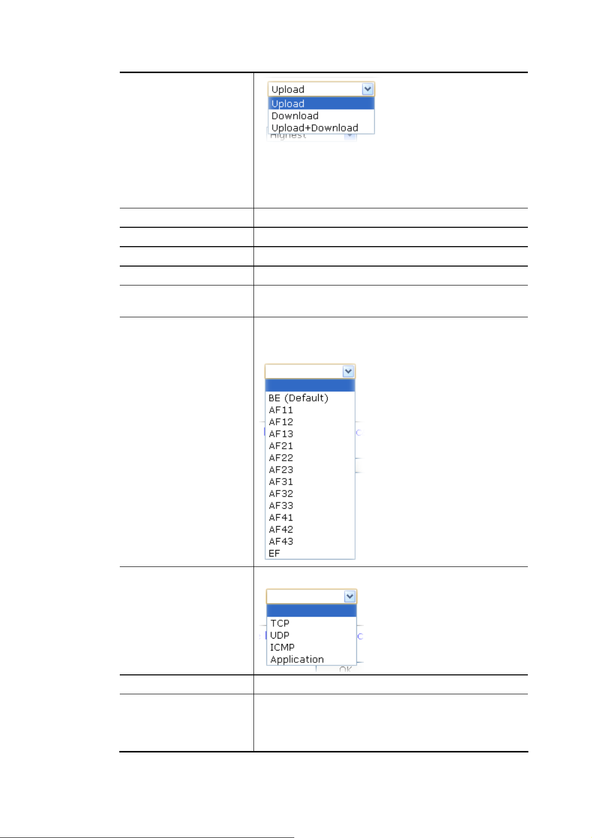
Download - apply to incoming traffic only.
Upload - apply to outgoing traffic only.
Upload+Download - apply to both incoming and outgoing
traffic.
Name
Group
Dest. IP address
Src. IP address
Packet Length
DSCP
Define the name of such rule.
Determine the priority of such rule.
Type the destination IP address influenced by such rule.
Type the source IP address influenced by such rule.
Specify the length of the packets. The adjustable range is
from 0 ~2048.
DSCP (Differentiated Services Code Point) allows each IP
packet to be tagged with different service class for different
network transmission. The default setting is "BE".
Protocol
Dest. Port/Src. Port
Application
Specify the protocol for such QoS rule.
It is available when TCP or UDP is selected as the protocol.
It is available when Application is selected as the protocol.
At present, there are eight applications which can be
selected for APP QoS management.
The usage of APP QoS can be seen by clicking APP QoS
86
VigorFly 210 Series User’s Guide
Page 95
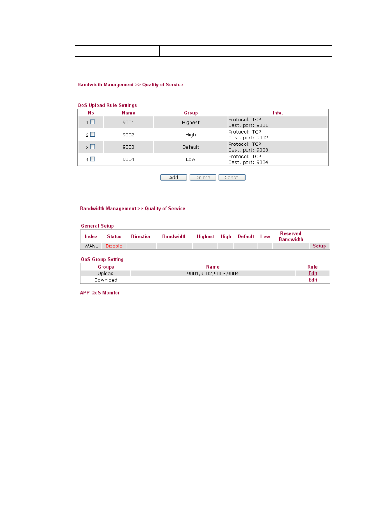
Monitor link.
After finished settings, click OK to save the settings. The new rule setting profile will be
added and displayed on the page. Below shows the QoS rule example for your reference:
In the QoS Group Setting page, you will see:
VigorFly 210 Series User’s Guide
87
Page 96

33..77 AApppplliiccaattiioonnss
Below shows the menu items for Applications.
33..77..11 DDyynnaammiicc DDNNSS
The ISP often provides you with a dynamic IP address when you connect to the Internet via
your ISP. It means that the public IP address assigned to your router changes each time you
access the Internet. The Dynamic DNS feature lets you assign a domain name to a dynamic
WAN IP address. It allows the router to update its online WAN IP address mappings on the
specified Dynamic DNS server. Once the router is online, you will be able to use the
registered domain name to access the router or internal virtual servers from the Internet. It is
particularly helpful if you host a web server, FTP server, or other server behind the router.
Before you use the Dynamic DNS feature, you have to apply for free DDNS service to the
DDNS service providers. The router provides up to three accounts from three different DDNS
service providers. Basically, Vigor routers are compatible with the DDNS services supplied by
most popular DDNS service providers such as www.dyndns.org, www.no-ip.com,
www.dtdns.com, www.changeip.com, www.dynamic- nameserver.com. You should visit
their websites to register your own domain name for the router.
Available parameters are listed below:
Item Description
Enable Dynamic DNS
Service Provider
Check this box to enable the current account. If you did
check the box, you will see a check mark appeared on the
Active column of the previous web page in step 2).
Select the service provider for the DDNS account.
88
VigorFly 210 Series User’s Guide
Page 97

If you choose None, such function will be disabled.
Domain name
Username
Password
Forced Update Period
After finishing all the settings here, please click OK to save the configuration.
33..77..22 880022..11dd SSppaannnniinngg TTrreeee
The Spanning Tree Protocol (STP) is a link layer network protocol that ensures a loop-free
topology for any bridged LAN. Check the box to invoke such feature and click OK to save it.
Type in one domain name that you applied previously. Use
the drop down list to choose the desired domain.
Type in the login name that you set for applying domain.
Type in the password that you set for applying domain.
Select a time interval for updating from the NTP server.
33..77..33 LLLLTTDD
Link Layer Topology Discovery (LLTD) is a proprietary Link Layer protocol for network
topology discovery and quality of service diagnostics. This protocol is included in Windows
Vista and Windows 7. Check the box to invoke such feature and click OK to save it.
VigorFly 210 Series User’s Guide
89
Page 98

33..77..44 IIGGMMPP
IGMP is the abbreviation of Internet Group Management Protocol. It is a communication
protocol which is mainly used for managing the membership of Internet Protocol multicast
groups. Check the box to invoke such feature and click OK to save it.
33..77..55 HH..332233
The H.323 ALG allows incoming and outgoing VoIP calls passing through NAT. If required,
check the box and click OK to save the settings.
33..77..66 UUPPnnPP
The UPnP (Universal Plug and Play) protocol is supported to bring to network connected devices the ease of installation and configuration which is already available for directly connected PC peripherals with the existing Windows 'Plug and Play' system. For NAT routers, the major feature of UPnP on the router is “NAT Traversal”. This enables applications inside the firewall to automatically open the ports that they need to pass through a router. It is more reliable than requiring a router to work out by itself which ports need to be opened. Further, the user does not have to manually set up port mappings or a DMZ. UPnP is available on Windows XP and the router provide the associated support for MSN Messenger to allow full use of the voice, video and messaging features.
After setting Enable UPnP setting, an icon of IP Broadband Connection on Router on
Windows XP/Network Connections will appear. The connection status and control status will
be able to be activated. The NAT Traversal of UPnP enables the multimedia features of your
90
VigorFly 210 Series User’s Guide
Page 99

applications to operate. This has to manually set up port mappings or use other similar
methods. The screenshots below show examples of this facility.
The UPnP facility on the router enables UPnP aware applications such as MSN Messenger to
discover what are behind a NAT router. The application will also learn the external IP address
and configure port mappings on the router. Subsequently, such a facility forwards packets from
the external ports of the router to the internal ports used by the application.
The reminder as regards concern about Firewall and UPnP
Can't work with Firewall Software
Enabling firewall applications on your PC may cause the UPnP function not working
properly. This is because these applications will block the accessing ability of some network
ports.
Security Considerations
Activating the UPnP function on your network may incur some security threats. You should
consider carefully these risks before activating the UPnP function.
Some Microsoft operating systems have found out the UPnP weaknesses and hence
you need to ensure that you have applied the latest service packs and patches.
Non-privileged users can control some router functions, including removing and
adding port mappings.
VigorFly 210 Series User’s Guide
91
Page 100
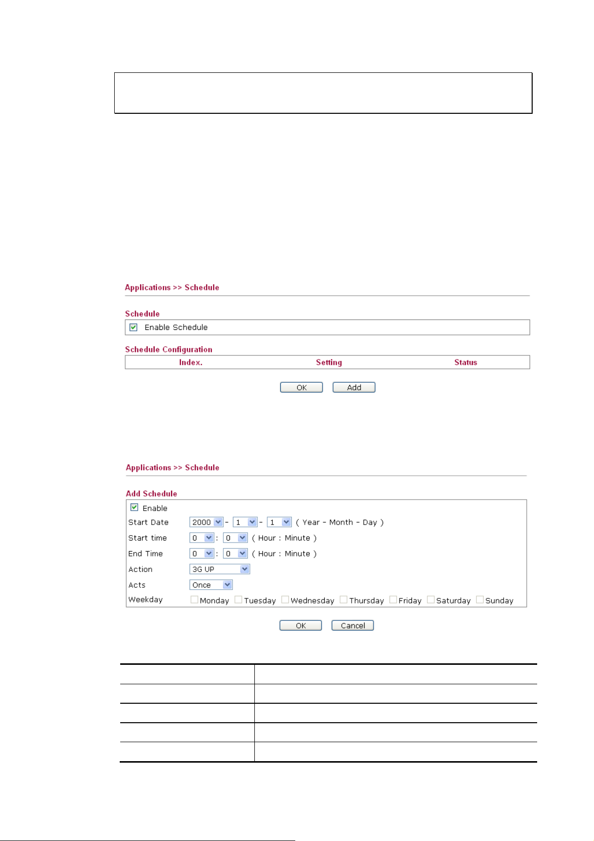
The UPnP function dynamically adds port mappings on behalf of some UPnP-aware
applications. When the applications terminate abnormally, these mappings may not be
removed.
33..77..77 SScchheedduullee
The Vigor router has a built-in real time clock which can update itself manually or
automatically by means of Network Time Protocols (NTP). As a result, you can not only
schedule the router to dialup to the Internet at a specified time, but also restrict Internet access
to certain hours so that users can connect to the Internet only during certain hours, say,
business hours. The schedule is also applicable to other functions.
You have to set your time before set schedule. In System Maintenance>> Time and Date
menu, press Inquire Time button to set the Vigor router’s clock to current time of your PC.
The clock will reset once if you power down or reset the router. There is another way to set up
time. You can inquiry an NTP server (a time server) on the Internet to synchronize the router’s
clock. This method can only be applied when the WAN connection has been built up.
You can set up to 15 schedules.
To add a schedule, please click any index, say Index No. 1. The detailed settings of the call
schedule with index 1 are shown below.
Available settings are explained as follows:
Item Description
Enable
Start Date
Check to enable the schedule.
Specify the starting date of the schedule.
Start Time
End Time
Specify the starting time of the schedule.
Specify the ending time of the schedule.
92
VigorFly 210 Series User’s Guide
 Loading...