

Page 1

Page 2

Vigor2860 Series
VDSL2 Security Firewall
User’s Guide
Vigor2860 Series User’s Guide
Version: 3.1
Firmware Version: V3.7.8.2
(For future update, please visit DrayTek web site)
Date: May 14, 2015
ii
Page 3

Intellectual Property Rights (IPR) Information
Copyrights
Trademarks
© All rights reserved. This publication contains information that is protected by
copyright. No part may be reproduced, transmitted, transcribed, stored in a retrieval
system, or translated into any language without written permission from the copyright
holders.
The following trademarks are used in this document:
Microsoft is a registered trademark of Microsoft Corp.
Windows, Windows 95, 98, Me, NT, 2000, XP, Vista, 7 and Explorer are
trademarks of Microsoft Corp.
Apple and Mac OS are registered trademarks of Apple Inc.
Other products may be trademarks or registered trademarks of their respective
manufacturers.
Safety Instructions and Approval
Safety
Instructions
Warranty
Read the installation guide thoroughly before you set up the router.
The router is a complicated electronic unit that may be repaired only be
authorized and qualified personnel. Do not try to open or repair the router
yourself.
Do not place the router in a damp or humid place, e.g. a bathroom.
The router should be used in a sheltered area, within a temperature range of +5 to
+40 Celsius.
Do not expose the router to direct sunlight or other heat sources. The housing and
electronic components may be damaged by direct sunlight or heat sources.
Do not deploy the cable for LAN connection outdoor to prevent electronic shock
hazards.
Keep the package out of reach of children.
When you want to dispose of the router, please follow local regulations on
conservation of the environment.
We warrant to the original end user (purchaser) that the router will be free from any
defects in workmanship or materials for a period of two (2) years from the date of
purchase from the dealer. Please keep your purchase receipt in a safe place as it serves
as proof of date of purchase. During the warranty period, and upon proof of purchase,
should the product have indications of failure due to faulty workmanship and/or
materials, we will, at our discretion, repair or replace the defective products or
components, without charge for either parts or labor, to whatever extent we deem
necessary tore-store the product to proper operating condition. Any replacement will
consist of a new or re-manufactured functionally equivalent product of equal value, and
will be offered solely at our discretion. This warranty will not apply if the product is
modified, misused, tampered with, damaged by an act of God, or subjected to abnormal
working conditions. The warranty does not cover the bundled or licensed software of
other vendors. Defects which do not significantly affect the usability of the product will
not be covered by the warranty. We reserve the right to re vi se the ma nual and onli ne
documentation and to make changes from time to time in the contents hereof without
obligation to notify any person of such revision or changes.
Be a Registered
Owner
Firmware & Tools
Updates
Web registration is preferred. You can register your Vigor router via
http://www.draydek.com.
Due to the continuous evolution of DrayTek technology, all routers will be regularly
upgraded. Please consult the DrayTek web site for more information on newest
firmware, tools and documents.
http://www.draytek.com
iii
Vigor2860 Series User’s Guide
Page 4

European Community Declarations
Manufacturer: DrayTek Corp.
Address: No. 26, Fu Shing Road, Hukou Township, Hsinchu Industrial Park, Hsinchu County, Taiwan 303
Product: Vigor2860 Series Router
DrayTek Corp. declares that Vigor2860 Series of routers are in compliance with the following essential
requirements and other relevant provisions of R&TTE 1999/5/EC, ErP 2009/125/EC and RoHS 2011/65/EU
The product conforms to the requirements of Electro-Magnetic Compatibility (EMC) Directive 2004/108/EC by
complying with the requirements set forth in EN55022/Class B and EN55024/Class B.
The product conforms to the requirements of Low Voltage (LVD) Directive 2006/95/EC by complying with the
requirements set forth in EN60950-1.
This product is designed for the DSL and 2.4GHz/5GHz WLAN network throughout the EC region.
Regulatory Information
Federal Communication Commission Interference Statement
This equipment has been tested and found to comply with the limits for a Class B digital device, pursuant to Part
15 of the FCC Rules. These limits are designed to provide reasonable protection against harmful interference in a
residential installation. This equipment generates, uses and can radiate radio frequency energy and, if not installed
and used in accordance with the instructions, may cause harmful interference to radio communications. However,
there is no guarantee that interference will not occur in a particular installation. If this equipment does cause
harmful interference to radio or televisi o n recept i on , whi ch can be determined by turning the equipment of f and
on, the user is encouraged to try to correct the interference by one of the following measures:
.
Reorient or relocate the receiving antenna.
Increase the separation between the equipment and receiver.
Connect the equipment into an outlet on a circuit different from that to which the receiver is connected.
Consult the dealer or an experienced radio/TV technician for help.
This device complies with Part 15 of the FCC Rules. Operation is subject to the following two conditions:
(1) This device may not cause harmful interference, and
(2) This device may accept any interference received, including interference that may cause undesired operation.
The antenna/transmitter should be kept at least 20 cm away from human body.
DrayTek Vigor2860 series VDSL2/ADSL2+ routers are compliant with 47 C.F.R. Part 68.
More update, please visit www.draytek.com.
Vigor2860 Series User’s Guide
iv
Page 5

TTaabbllee ooff CCoonntteennttss
Introduction...................................................................................................1
1.1 Web Configuration Buttons Explanation................................................................................. 2
1.2 LED Indicators and Connectors.............................................................................................. 3
1.2.1 For Vigor2860................................................................................................................... 3
1.2.2 For Vigor2860ac / Vigor2860n-plus / Vigor2860n ............................................................ 5
1.2.3 For Vigor2860Vac / Vigor2860Vn-plus............................................................................. 8
1.3 Hardware Installation ............................................................................................................10
1.3.1 Possible Installation for Vigor2860n............................................................................... 10
1.3.2 Possible Installation for Vigor2860Vac........................................................................... 11
1.3.3 Possible Installation for Vigor2860Vn-Plus..................................................................... 12
1.4 Printer Installation ................................................................................................................. 13
1.5 Accessing Web Page............................................................................................................ 21
1.6 Changing Password.............................................................................................................. 22
1.7 Introducing Dashboard.......................................................................................................... 24
1.7.1 Virtual Panel ................................................................................................................... 24
1.7.2 Name with a Link............................................................................................................ 25
1.7.3 Quick Access for Common Used Menu.......................................................................... 25
1.7.4 GUI Map ......................................................................................................................... 27
1.7.5 Web Console.................................................................................................................. 28
1.7.6 Config Backup ................................................................................................................ 29
1.7.7 Logout............................................................................................................................. 29
1.8 Online St atus......................................................................................................................... 29
1.8.1 Physical Connection.......................................................................................................29
1.8.2 Virtual WAN.................................................................................................................... 32
1.9 Saving Configuration............................................................................................................. 32
Quick Setup.................................................................................................34
2.1 Quick Start Wizard................................................................................................................ 34
2.1.1 For WAN1 (ADSL/VDSL2).............................................................................................. 36
2.1.2 For WAN2 (Ethernet)...................................................................................................... 42
2.1.3 For WAN3/WAN4 (USB)................................................................................................. 51
2.2 Service Activation Wizard...................................................................................................... 53
2.3 VPN Client Wizard ................................................................................................................56
2.4 VPN Server Wizard............................................................................................................... 62
2.5 Wireless Wizard.................................................................................................................... 67
2.6 VoIP Wizard........................................................................................................................... 71
2.7 Registering Vigor Router....................................................................................................... 73
v
Vigor2860 Series User’s Guide
Page 6

Advanced Configuration............................................................................76
3.1 WAN...................................................................................................................................... 76
3.1.1 Basics of Internet Protocol (IP) Network......................................................................... 76
3.1.2 General Setup................................................................................................................. 78
3.1.3 Internet Access............................................................................................................... 85
3.1.4 Multi-PVC/VLAN........................................................................................................... 115
3.1.5 WAN Budget................................................................................................................. 122
3.2 LAN ..................................................................................................................................... 125
3.2.1 Basics of LAN ............................................................................................................... 125
3.2.2 General Setup............................................................................................................... 127
3.2.3 Static Route.................................................................................................................. 137
3.2.4 VLAN............................................................................................................................. 142
3.2.5 Bind IP to MAC............................................................................................................. 146
3.2.6 LAN Port Mirror............................................................................................................. 148
3.2.7 Wired 802.1x................................................................................................................. 149
3.2.8 Web Portal Setup.......................................................................................................... 150
3.3 Load-Balance /Route Policy................................................................................................ 152
3.4 NAT .....................................................................................................................................162
3.4.1 Port Redirection............................................................................................................ 163
3.4.2 DMZ Host...................................................................................................................... 167
3.4.3 Open Ports.................................................................................................................... 170
3.4.4 Port Triggering..............................................................................................................172
3.5 Firewall................................................................................................................................ 175
3.5.1 Basics for Firewall......................................................................................................... 175
3.5.2 General Setup............................................................................................................... 177
3.5.3 Filter Setup ................................................................................................................... 182
3.5.4 DoS Defense ................................................................................................................ 190
3.6 User Management............................................................................................................... 194
3.6.1 General Setup............................................................................................................... 195
3.6.2 User Profile................................................................................................................... 197
3.6.3 User Group................................................................................................................... 202
3.6.4 User Online Status........................................................................................................ 203
3.7 Objects Settings..................................................................................................................204
3.7.1 IP Object....................................................................................................................... 204
3.7.2 IP Group ....................................................................................................................... 207
3.7.3 IPv6 Object................................................................................................................... 208
3.7.4 IPv6 Group.................................................................................................................... 210
3.7.5 Service Type Object ..................................................................................................... 211
3.7.6 Service Type Group...................................................................................................... 213
3.7.7 Keyword Object ............................................................................................................215
3.7.8 Keyword Group............................................................................................................. 217
3.7.9 File Extension Object.................................................................................................... 218
3.7.10 SMS/Mail Service Object............................................................................................ 220
3.7.11 Notification Object....................................................................................................... 225
3.8 CSM Profile......................................................................................................................... 227
3.8.1 APP Enforcement Profile.............................................................................................. 228
3.8.2 APPE Signature Upgrade............................................................................................. 232
3.8.3 URL Content Filter Profile............................................................................................. 234
3.8.4 Web Content Filter Profile............................................................................................. 238
Vigor2860 Series User’s Guide
vi
Page 7

3.8.5 DNS Filter Profile..........................................................................................................242
3.9 Bandwidth Management ..................................................................................................... 244
3.9.1 Sessions Limit............................................................................................................... 244
3.9.2 Bandwidth Limit ............................................................................................................246
3.9.3 Quality of Service.......................................................................................................... 248
3.10 Applications....................................................................................................................... 257
3.10.1 Dynamic DNS............................................................................................................. 257
3.10.2 LAN DNS / DNS Forwarding ...................................................................................... 260
3.10.3 Schedule..................................................................................................................... 264
3.10.4 RADIUS/TACACS+ .................................................................................................... 266
3.10.5 LDAP /Active Directory Setup..................................................................................... 268
3.10.6 UPnP........................................................................................................................... 271
3.10.7 IGMP........................................................................................................................... 272
3.10.8 Wake on LAN.............................................................................................................. 273
3.10.9 SMS / Mail Alert Service............................................................................................. 274
3.10.10 Bonjour ..................................................................................................................... 276
3.11 VPN and Remote Access.................................................................................................. 279
3.11.1 Remote Access Control.............................................................................................. 280
3.11.2 PPP General Setup .................................................................................................... 280
3.11.3 IPsec General Setup................................................................................................... 282
3.11.4 IPsec Peer Identity...................................................................................................... 283
3.11.5 Remote Dial-in User ................................................................................................... 285
3.11.6 LAN to LAN................................................................................................................. 288
3.11.7 VPN TRUNK Management......................................................................................... 300
3.11.8 Connection Management ........................................................................................... 309
3.12 Certificate Management.................................................................................................... 310
3.12.1 Local Certificate.......................................................................................................... 310
3.12.2 Trusted CA Certificate ................................................................................................ 314
3.12.3 Certificate Backup....................................................................................................... 316
3.13 Central VPN Management................................................................................................ 317
3.13.1 General Setup............................................................................................................. 317
3.13.2 CPE Management ...................................................................................................... 320
3.13.3 VPN Management ...................................................................................................... 326
3.13.4 Log & Alert..................................................................................................................328
3.14 Central AP Management................................................................................................... 329
3.14.1 Status.......................................................................................................................... 329
3.14.2 WLAN Profile.............................................................................................................. 330
3.14.3 AP Maintenance ......................................................................................................... 334
3.14.4 AP Map....................................................................................................................... 335
3.14.5 Traffic Graph............................................................................................................... 338
3.14.6 Rogue AP Detection................................................................................................... 339
3.14.7 Load Balance.............................................................................................................. 343
3.14.8 Function Support List.................................................................................................. 345
3.15 VoIP................................................................................................................................... 346
3.15.1 DialPlan ...................................................................................................................... 348
3.15.2 SIP Accounts.............................................................................................................. 357
3.15.3 Phone Settings ...........................................................................................................362
3.15.4 Status.......................................................................................................................... 367
3.16 Wireless LAN(2.4GHz/5GHz) ........................................................................................... 369
3.16.1 Basic Concepts........................................................................................................... 369
3.16.2 General Setup............................................................................................................. 372
3.16.3 Security....................................................................................................................... 374
vii
Vigor2860 Series User’s Guide
Page 8

3.16.4 Access Control............................................................................................................ 376
3.16.5 WPS............................................................................................................................ 377
3.16.6 WDS............................................................................................................................ 380
3.16.7 Advanced Setting........................................................................................................ 384
3.16.8 WMM Configuration.................................................................................................... 386
3.16.9 Station Control............................................................................................................ 388
3.16.10 AP Discovery............................................................................................................ 388
3.16.11 Station List................................................................................................................390
3.17 SSL VPN........................................................................................................................... 391
3.17.1 General Setup............................................................................................................. 391
3.17.2 SSL Web Proxy .......................................................................................................... 392
3.17.3 SSL Application .......................................................................................................... 394
3.17.4 User Account.............................................................................................................. 396
3.17.5 User Group................................................................................................................. 400
3.17.6 Online User Status...................................................................................................... 402
3.18 USB Application................................................................................................................ 403
3.18.1 USB General Settings................................................................................................. 403
3.18.2 USB User Management.............................................................................................. 405
3.18.3 File Explorer................................................................................................................ 407
3.18.4 USB Device Status..................................................................................................... 408
3.18.5 Temperature Sensor................................................................................................... 409
3.18.6 Modem Support List.................................................................................................... 411
3.19 System Maintenance......................................................................................................... 412
3.19.1 System Status............................................................................................................. 412
3.19.2 TR-069........................................................................................................................ 414
3.19.3 Administrator Password.............................................................................................. 416
3.19.4 User Password ........................................................................................................... 418
3.19.5 Login Page Greeting................................................................................................... 420
3.19.6 Configuration Backup ................................................................................................. 422
3.19.7 Syslog/Mail Alert.........................................................................................................425
3.19.8 Time and Date............................................................................................................ 428
3.19.9 SNMP.......................................................................................................................... 429
3.19.10 Management............................................................................................................. 431
3.19.11 Reboot System......................................................................................................... 434
3.19.12 Firmware Upgrade.................................................................................................... 435
3.19.13 Modem Code Upgrade ............................................................................................. 436
3.19.14 Activation.................................................................................................................. 436
3.20 Diagnostics........................................................................................................................ 437
3.20.1 Dial-out Triggering...................................................................................................... 438
3.20.2 Routing Table ............................................................................................................. 439
3.20.3 ARP Cache Table....................................................................................................... 440
3.20.4 IPv6 Neighbour Table................................................................................................. 440
3.20.5 DHCP Table................................................................................................................ 441
3.20.6 NAT Sessions Table................................................................................................... 442
4.20.7 DNS Cache Table....................................................................................................... 443
3.20.8 Ping Diagnosis............................................................................................................ 444
3.20.9 Data Flow Monitor....................................................................................................... 445
3.20.10 Traffic Graph............................................................................................................. 447
3.20.11 Trace Route.............................................................................................................. 448
3.20.12 Syslog Explorer......................................................................................................... 449
3.20.13 TSPC Status.............................................................................................................450
3.20.14 DSL Status................................................................................................................ 451
3.21 External Devices............................................................................................................... 452
3.21.1 All Devices.................................................................................................................. 452
Vigor2860 Series User’s Guide
viii
Page 9

Tutorials and Applications.......................................................................454
4.1 How to configure settings for IPv6 Service in Vigor2860.................................................... 454
4.2 How can I get the files from USB storage device connecting to Vigor router?................... 467
4.3 How to Build a LAN-to-LAN VPN Between Remote Office and Headquarter via IPsec Tunnel
(Main Mode).............................................................................................................................. 470
4.4 How to Optimize the Bandwidth through QoS Technology................................................. 474
4.5 QoS Setting Example.......................................................................................................... 479
4.6 How to Implement the LDAP/AD Authentication for User Management?........................... 484
4.7 How to use Landing Page Feature ..................................................................................... 487
4.8 How to Send a Notification to Specified Phone Number via SMS Service in WAN
Disconnection............................................................................................................................ 492
4.9 How to Create an Account for MyVigor............................................................................... 496
4.9.1 Create an Account via Vigor Router............................................................................. 496
4.9.2 Create an Account via MyVigor Web Site .................................................................... 500
4.10 How to Setup Address Mapping........................................................................................504
4.11 How to Configure Certain Computers Accessing to Internet ............................................ 508
4.12 How to Block Facebook Service Accessed by the Users via Web Content Filter / URL
Content Filter............................................................................................................................. 512
4.13 How to use AP Management function (in Vigor2860) to check AP status and deploy WLAN
profile......................................................................................................................................... 517
4.14 CVM Application - How to manage the CPE (router) through Vigor2860 series? ............ 520
4.15 CVM Application - How to build the VPN between remote devices and Vigor2860 series?
.................................................................................................................................................. 524
4.16 CVM Application - How to upgrade CPE firmware through Vigor2860 series?................ 526
4.17 How to setup Load Balance for Packets?......................................................................... 529
4.18 How to authenticate clients via User Management........................................................... 531
Trouble Shooting ......................................................................................543
5.1 Checking If the Hardware Status Is OK or Not....................................................................543
5.2 Checking If the Network Connection Settings on Your Computer Is OK or Not ................. 544
5.3 Pinging the Router from Your Computer............................................................................. 547
5.4 Checking If the ISP Settings are OK or Not........................................................................ 548
5.5 Problems for 3G/4G Network Connection........................................................................... 549
5.6 Backing to Factory Default Setting If Necessary ................................................................ 550
5.7 Contacting DrayTek............................................................................................................. 551
Appendix I: VLAN Applications on Vigor Router ........................................................553
Telnet Command Reference..........................................................................................561
ix
Vigor2860 Series User’s Guide
Page 10

Accessing Telnet of Vigor2860.................................................................................................. 561
Telnet Command: adsl txpct /adsl rxpct ................................................................................ 561
Telnet Command: adsl status................................................................................................ 562
Telnet Command: adsl ppp.................................................................................................... 562
Telnet Command: adsl bridge................................................................................................ 564
Telnet Command: adsl idle.................................................................................................... 565
Telnet Command: adsl drivemode......................................................................................... 565
Telnet Command: adsl reboot ............................................................................................... 565
Telnet Command: adsl oamlb................................................................................................ 566
Telnet Command: adsl vcilimit............................................................................................... 566
Telnet Command: adsl annex................................................................................................ 568
Telnet Command: adsl automode ......................................................................................... 568
Telnet Command: adsl optn................................................................................................... 568
Telnet Command: adsl savecfg............................................................................................. 569
Telnet Command: adsl vendorid............................................................................................ 569
Telnet Command: adsl atm.................................................................................................... 570
Telnet Command: adsl pvcbinding........................................................................................ 571
Telnet Command: adsl snr..................................................................................................... 571
Telnet Command: bpa........................................................................................................... 572
Telnet Command: csm appe prof.......................................................................................... 573
Telnet Command: csm appe p2p .......................................................................................... 574
Telnet Command: csm appe prot.......................................................................................... 575
Telnet Command: csm appe misc......................................................................................... 575
Telnet Command: csm ucf..................................................................................................... 577
Telnet Command: csm ucf obj INDEX uac............................................................................ 578
Telnet Command: csm ucf obj INDEX wf.............................................................................. 581
Telnet Command: csm wcf.................................................................................................... 582
Telnet Command: ddns log.................................................................................................... 585
Telnet Command: ddns time.................................................................................................. 585
Telnet Command: dos ........................................................................................................... 586
Telnet Command: exit............................................................................................................ 588
Telnet Command: Internet..................................................................................................... 588
Telnet Command: ip 2ndsubnet............................................................................................. 589
Telnet Command: ip 2ndaddr................................................................................................ 590
Telnet Command: ip 2ndmask............................................................................................... 590
Telnet Command: ip aux........................................................................................................ 591
Telnet Command: ip addr...................................................................................................... 592
Telnet Command: ip nmask................................................................................................... 593
Telnet Command: ip arp........................................................................................................ 593
Telnet Command: ip dhcpc.................................................................................................... 594
Telnet Command: ip ping....................................................................................................... 595
Telnet Command: ip tracert................................................................................................... 596
Telnet Command: ip telnet..................................................................................................... 596
Telnet Command: ip rip .........................................................................................................597
Telnet Command: ip wanrip................................................................................................... 598
Telnet Command: ip route..................................................................................................... 600
Telnet Command: ip igmp_proxy........................................................................................... 602
Telnet Command: ip wanaddr................................................................................................ 604
Telnet Command: ip wanttr.................................................................................................... 604
Telnet Command: ip dmz....................................................................................................... 604
Telnet Command: ip session................................................................................................. 605
Telnet Command: ip bandwidth............................................................................................. 606
Telnet Command: ip bindmac................................................................................................ 607
Telnet Command: ip maxnatuser........................................................................................... 609
Telnet Command: ip6 addr.................................................................................................... 609
Telnet Command: ip6 dhcp req_opt...................................................................................... 610
Telnet Command: ip6 dhcp client.......................................................................................... 611
Telnet Command: ip6 dhcp server ........................................................................................ 612
Telnet Command: ip6 internet ............................................................................................... 614
Telnet Command: ip6 neigh................................................................................................... 615
Vigor2860 Series User’s Guide
x
Page 11

Telnet Command: ip6 pneigh................................................................................................. 617
Telnet Command: ip6 route................................................................................................... 617
Telnet Command: ip6 ping..................................................................................................... 618
Telnet Command: ip6 tracert................................................................................................. 620
Telnet Command: ip6 tspc..................................................................................................... 620
Telnet Command: ip6 radvd .................................................................................................. 621
Telnet Command: ip6 mngt ................................................................................................... 622
Telnet Command: ip6 online.................................................................................................. 623
Telnet Command: ip6 aiccu................................................................................................... 624
Telnet Command: ip6 ntp ...................................................................................................... 625
Telnet Command: ipf view..................................................................................................... 625
Telnet Command: ipf set........................................................................................................ 626
Telnet Command: ipf rule ...................................................................................................... 628
Telnet Command: ipf flowtrack.............................................................................................. 634
Telnet Command: Log........................................................................................................... 635
Telnet Command: mngt ftpport.............................................................................................. 636
Telnet Command: mngt httpport............................................................................................ 637
Telnet Command: mngt httpsport.......................................................................................... 637
Telnet Command: mngt telnetport......................................................................................... 637
Telnet Command: mngt sshport ............................................................................................ 638
Telnet Command: mngt ftpserver.......................................................................................... 638
Telnet Command: mngt noping ............................................................................................. 639
Telnet Command: mngt defenseworm .................................................................................. 640
Telnet Command: mngt rmtcfg.............................................................................................. 640
Telnet Command: mngt lanaccess........................................................................................ 641
Telnet Command: mngt echoicmp......................................................................................... 643
Telnet Command: mngt accesslist ........................................................................................ 643
Telnet Command: mngt snmp ............................................................................................... 644
Telnet Command: msubnet switch........................................................................................ 645
Telnet Command: msubnet addr........................................................................................... 646
Telnet Command: msubnet nmask........................................................................................ 646
Telnet Command: msubnet status......................................................................................... 647
Telnet Command: msubnet dhcps......................................................................................... 647
Telnet Command: msubnet nat ............................................................................................. 648
Telnet Command: msubnet gateway..................................................................................... 649
Telnet Command: msubnet ipcnt........................................................................................... 649
Telnet Command: msubnet talk............................................................................................. 650
Telnet Command: msubnet startip ........................................................................................ 651
Telnet Command: msubnet pppip ......................................................................................... 652
Telnet Command: msubnet nodetype ................................................................................... 653
Telnet Command: msubnet primWINS.................................................................................. 654
Telnet Command: msubnet secWINS................................................................................... 654
Telnet Command: msubnet tftp ............................................................................................. 656
Telnet Command: msubnet mtu ............................................................................................ 656
Telnet Command: object ip obj.............................................................................................. 657
Telnet Command: object ip grp.............................................................................................. 659
Telnet Command: object ipv6 obj.......................................................................................... 662
Telnet Command: object ipv6 grp.......................................................................................... 663
Telnet Command: object service obj ..................................................................................... 665
Telnet Command: object service grp..................................................................................... 667
Telnet Command: object kw.................................................................................................. 668
Telnet Command: object fe.................................................................................................... 670
Telnet Command: port........................................................................................................... 673
Telnet Command: portmaptime............................................................................................. 673
Telnet Command: prn............................................................................................................ 674
Telnet Command: qos setup.................................................................................................. 675
Telnet Command: qos class.................................................................................................. 678
Telnet Command: qos type.................................................................................................... 680
Telnet Command: quit ........................................................................................................... 681
Telnet Command: show lan................................................................................................... 681
xi
Vigor2860 Series User’s Guide
Page 12

Telnet Command: show dmz................................................................................................. 682
Telnet Command: show dns.................................................................................................. 682
Telnet Command: show openport ......................................................................................... 682
Telnet Command: show nat................................................................................................... 682
Telnet Command: show portmap........................................................................................... 683
Telnet Command: show pmtime............................................................................................ 683
Telnet Command: show session............................................................................................ 683
Telnet Command: show status.............................................................................................. 684
Telnet Command: show adsl................................................................................................. 684
Telnet Command: show statistic............................................................................................ 685
Telnet Command: srv dhcp badip.......................................................................................... 686
Telnet Command: srv dhcp public......................................................................................... 686
Telnet Command: srv dhcp dns1........................................................................................... 687
Telnet Command: srv dhcp dns2........................................................................................... 687
Telnet Command: srv dhcp frcdnsmanl................................................................................. 689
Telnet Command: srv dhcp gateway..................................................................................... 689
Telnet Command: srv dhcp ipcnt........................................................................................... 690
Telnet Command: srv dhcp off............................................................................................... 690
Telnet Command: srv dhcp on............................................................................................... 690
Telnet Command: srv dhcp relay........................................................................................... 690
Telnet Command: srv dhcp startip......................................................................................... 691
Telnet Command: srv dhcp status......................................................................................... 691
Telnet Command: srv dhcp leasetime................................................................................... 692
Telnet Command: srv dhcp nodetype.................................................................................... 692
Telnet Command: srv dhcp primWINS.................................................................................. 694
Telnet Command: srv dhcp secWINS ................................................................................... 694
Telnet Command: srv dhcp expired_RecycleIP .................................................................... 696
Telnet Command: srv dhcp tftp.............................................................................................. 696
Telnet Command: srv dhcp option......................................................................................... 696
Telnet Command: srv nat dmz............................................................................................... 698
Telnet Command: srv nat ipsecpass..................................................................................... 699
Telnet Command: srv nat openport....................................................................................... 699
Telnet Command: srv nat portmap........................................................................................ 701
Telnet Command: srv nat showall......................................................................................... 703
Telnet Command: switch -i.................................................................................................... 704
Telnet Command: switch on.................................................................................................. 704
Telnet Command: switch off.................................................................................................. 705
Telnet Command: switch list.................................................................................................. 705
Telnet Command: switch clear.............................................................................................. 705
Telnet Command: switch query............................................................................................. 706
Telnet Command: sys admin................................................................................................. 706
Telnet Command: sys adminuser.......................................................................................... 706
Telnet Command: sys bonjour............................................................................................... 707
Telnet Command: sys cfg...................................................................................................... 709
Telnet Command: sys cmdlog............................................................................................... 709
Telnet Command: sys ftpd..................................................................................................... 709
Telnet Command: sys domainname...................................................................................... 710
Telnet Command: sys iface................................................................................................... 710
Telnet Command: sys name.................................................................................................. 712
Telnet Command: sys passwd............................................................................................... 712
Telnet Command: sys reboot................................................................................................. 712
Telnet Command: sys autoreboot ......................................................................................... 714
Telnet Command: sys commit............................................................................................... 714
Telnet Command: sys tftpd.................................................................................................... 714
Telnet Command: sys cc....................................................................................................... 714
Telnet Command: sys version............................................................................................... 715
Telnet Command: sys qrybuf................................................................................................. 715
Telnet Command: sys pollbuf................................................................................................ 716
Telnet Command: sys britask................................................................................................ 716
Telnet Command: sys tr069................................................................................................... 717
Vigor2860 Series User’s Guide
xii
Page 13

Telnet Command: sys sip_alg ............................................................................................... 719
Telnet Command: sys license................................................................................................ 719
Telnet Command: sys diag_log............................................................................................. 720
Telnet Command: testmail..................................................................................................... 722
Telnet Command: upnp off.................................................................................................... 722
Telnet Command: upnp on.................................................................................................... 722
Telnet Command: upnp nat................................................................................................... 723
Telnet Command: upnp service............................................................................................. 723
Telnet Command: upnp subscribe......................................................................................... 724
Telnet Command: upnp tmpvs............................................................................................... 725
Telnet Command: upnp wan.................................................................................................. 727
Telnet Command: usb list...................................................................................................... 727
Telnet Command: vigbrg on .................................................................................................. 728
Telnet Command: vigbrg off .................................................................................................. 728
Telnet Command: vigbrg status............................................................................................. 728
Telnet Command: vigbrg cfgip............................................................................................... 729
Telnet Command: vigbrg wan1on.......................................................................................... 729
Telnet Command: vigbrg wan1off.......................................................................................... 729
Telnet Command: vpn l2lset.................................................................................................. 729
Telnet Command: vpn l2lDrop............................................................................................... 730
Telnet Command: vpn dinset................................................................................................. 730
Telnet Command: vpn subnet................................................................................................ 732
Telnet Command: vpn setup.................................................................................................. 733
Telnet Command: vpn option................................................................................................. 735
Telnet Command: vpn mroute............................................................................................... 739
Telnet Command: vpn list...................................................................................................... 740
Telnet Command: vpn remote............................................................................................... 742
Telnet Command: vpn 2ndsubnet ......................................................................................... 742
Telnet Command: vpn NetBios.............................................................................................. 742
Telnet Command: vpn mss.................................................................................................... 743
Telnet Command: vpn ike...................................................................................................... 744
Telnet Command: vpn Multicast............................................................................................ 745
Telnet Command: vpn pass2nd............................................................................................. 745
Telnet Command: vpn pass2nat............................................................................................ 746
Telnet Command: wan ppp_mru........................................................................................... 746
Telnet Command: wan mtu.................................................................................................... 747
Telnet Command: wan DF_check......................................................................................... 747
Telnet Command: wan disable.............................................................................................. 749
Telnet Command: wan enable............................................................................................... 749
Telnet Command: wan forward.............................................................................................. 749
Telnet Command: wan status................................................................................................ 749
Telnet Command: wan vdsl................................................................................................... 750
Telnet Command: wan detect................................................................................................ 751
Telnet Command: wan lb....................................................................................................... 752
Telnet Command: wan mvlan................................................................................................ 753
Telnet Command: wan multifno............................................................................................. 754
Telnet Command: wl acl........................................................................................................ 756
Telnet Command: wl config................................................................................................... 757
Telnet Command: wl set........................................................................................................ 760
Telnet Command: wl act........................................................................................................ 761
Telnet Command: wl scan..................................................................................................... 761
Telnet Command: wl stamgt.................................................................................................. 763
Telnet Command: wl iso_vpn ................................................................................................ 764
Telnet Command: wl wpa...................................................................................................... 764
Telnet Command: wl wmm.................................................................................................... 764
Telnet Command: wl ht.......................................................................................................... 766
Telnet Command: wl restart................................................................................................... 767
Telnet Command: wl btnctl.................................................................................................... 768
Telnet Command: wl iwpriv & wl wlanconfig.......................................................................... 768
Telnet Command: wl efuse.................................................................................................... 768
xiii
Vigor2860 Series User’s Guide
Page 14

Telnet Command: wan vlan................................................................................................... 769
Telnet Command: wol............................................................................................................ 769
Telnet Command: user.......................................................................................................... 770
Telnet Command: nand bad /nand usage............................................................................. 774
Telnet Command: apm show /clear/discover/query.............................................................. 774
Telnet Command: apm profile ............................................................................................... 775
Telnet Command: apm cache................................................................................................ 776
Telnet Command: apm lbcfg.................................................................................................. 777
Telnet Command: apm napdetect......................................................................................... 779
Vigor2860 Series User’s Guide
xiv
Page 15

IInnttrroodduuccttiioonn
NNoottee:: TThhiiss iiss aa ggeenneerriicc IInntteerrnnaattiioonnaall vveerrssiioonn ooff tthhee
uusseerr gguuiiddee.. SSppeecciiffiiccaattiioonn,, ccoommppaattiibbiilliittyy aanndd ffeeaattuurreess
vvaarryy bbyy rreeggiioonn.. FFoorr ssppeecciiffiicc uusseerr gguuiiddeess ssuuiittaabbllee ffoorr
yyoouurr rreeggiioonn oorr pprroodduucctt,, pplleeaassee ccoonnttaacctt llooccaall
ddiissttrriibbuuttoorr..
Vigor2860 series is a VDSL2 router. It integrates IP layer QoS, NAT session/bandwidth
management to help users control works well with large bandwidth.
By adopting hardware-based VPN platform and hardware encryption of AES/DES/3DES, the
router increases the performance of VPN greatly, and offers several protocols (such as
IPsec/PPTP/L2TP) with up to 32 VPN tunnels.
The object-based design used in SPI (Stateful Packet Inspection) firewall allows users to set
firewall policy with ease. CSM (Content Security Management) provides users control and
management in IM (Instant Messenger) and P2P (Peer to Peer) more efficiency than before.
By the way, DoS/DDoS prevention and URL/Web content filter strengthen the security
outside and control inside. Object-based firewall is flexible and allows your network be safe.
User Management implemented on your router firmware can allow you to prevent any
computer from accessing your Internet connection without a username or password. You can
also allocate time budgets to your employees within office network.
With the 6-port Gigabit switch on the LAN side provides extremely high speed connectivity
for the highest speed local data transfer of any server or local PCs. The tagged VLANs
(IEEE802.1Q) can mark data with a VLAN identifier. This identifier can be carried through an
onward Ethernet switch to specific ports. The specific VLAN clients can also pick up this
identifier as it is just passed to the LAN. You can set the priorities for LAN-side QoS. You can
assign each of VLANs to each of the different IP subnets that the router may also be operating,
to provide even more isolation. The said functionality is tag-based Multi-subnet
(Multiple-Private LAN Subnets).
On the Wireless-equipped models (Vigor2860n/n plus/Vn/Vn plus) each of the wireless SSIDs
can also be grouped within one of the VLANs.
In addition, Vigor2860 series supports USB interface for connecting USB printer to share
printing function or 3G USB modem for network connection.
Vigor2860 series provides two-level management to simplify the configuration of network
connection. The user mode allows user accessing into WEB interface via simple configuration.
However, if users want to have advanced configurations, they can access into WEB interface
through admin mode.
1
Vigor2860 Series User’s Guide
Page 16
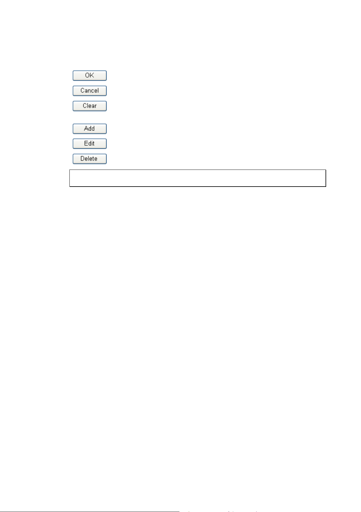
11..11 WWeebb CCoonnffiigguurraattiioonn BBuuttttoonnss EExxppllaannaattiioonn
Several main buttons appeared on the web pages are defined as the following:
Save and apply current settings.
Cancel current settings and recover to the previous saved settings.
Clear all the selections and parameters settings, including selection from
drop-down list. All the values must be reset with factory default settings.
Add new settings for specified item.
Edit the settings for the selected item.
Delete the selected item with the corresponding settings.
Note: For the other buttons shown on the web pages, please refer to Chapter 3, 4 for detailed
explanation.
Vigor2860 Series User’s Guide
2
Page 17

11..22 LLEEDD IInnddiiccaattoorrss aanndd CCoonnnneeccttoorrss
Before you use the Vigor router, please get acquainted with the LED indicators and connectors
first.
11..22..11 FFoorr VViiggoorr22886600
LED Status Explanation
WAN2
QoS
WCF On The Web Content Filter is active. (It is enabled from
VPN
LED on Connector
Left
WAN2
(Giga)
GigaLAN
1~6
LED
Right
LED
Left
LED
Right
LED
Blinking The router is powered on and running normally. ACT (Activity)
Off The router is powered off.
On Internet connection is ready.
Off Internet connection is not ready.
Blinking The data is transmitting.
On The QoS function is active.
On USB device is connected and ready for use. USB1~2
Blinking The data is transmitting.
On The router is ready to access Internet through DSL link.DSL
Blinking Slowly: The DSL connection is ready.
Quickly: The connection is training.
Firewall >> General Setup).
On The VPN tunnel is active.
Off VPN services are disabled
Blinking Traffic is passing through VPN tunnel.
On The DoS function is active. DoS
Blinking It will blink while detecting an attack.
On The port is connected.
Off The port is disconnected.
Blinking The data is transmitting.
On The port is connected with 1000Mbps.
Off The port is connected with 10/100Mbps
On The port is connected.
Off The port is disconnected.
Blinking The data is transmitting.
On The port is connected with 1000Mbps.
Off The port is connected with 10/100Mbps
3
Vigor2860 Series User’s Guide
Page 18

Interface Description
Factory Reset Restore the default settings. Usage: Turn on the router (ACT LED is
blinking). Press the hole and keep for more than 5 seconds. When you
see the ACT LED begins to blink rapidly than usual, release the button.
Then the router will restart with the factory default configuration.
USB Connecter for a USB device (for 3G/4G USB Modem or printer).
VDSL/ADSL Connecter for accessing the Internet.
WAN2 Connecter for local network devices or modem for accessing Internet.
GigaLAN (1-6) Connecters for local network devices.
PWR
ON/OFF
Connecter for a power adapter.
Power Switch.
Vigor2860 Series User’s Guide
4
Page 19

11..22..22 FFoorr VViiggoorr22886600aacc // VViiggoorr22886600nn--pplluuss // VViiggoorr2288660
0nn
LED Status Explanation
Blinking The router is powered on and running normally. ACT (Activity)
Off The router is powered off.
WAN2
On Internet connection is ready.
Off Internet connection is not ready.
Blinking The data is transmitting.
QoS
On The QoS function is active.
On USB device is connected and ready for use. USB
Blinking The data is transmitting.
On The router is ready to access Internet through DSL link.DSL
Blinking Slowly: The DSL connection is ready.
Quickly: The connection is training.
WCF On The Web Content Filter is active. (It is enabled from
Firewall >> General Setup).
2.4G/5G/WLAN
On
2.4G/5G: Wireless access point with bandwidth of
2.4GHz/5GHz is ready.
WLAN: Wireless access point is ready.
Blinking
It will blink slowly while wireless traffic goes through.
ACT and WLAN LEDs blink quickly and
simultaneously when WPS is working, and will return
to normal condition after two minutes. (You need to
setup WPS within 2 minutes.)
VPN
On The VPN tunnel is active.
Off
Blinking
VPN services are disabled.
Traffic is passing through VPN tunnel.
On The DoS function is active. DoS
Blinking It will blink while detecting an attack.
LED on Connector
WAN2
(Giga)
Left
LED
On The port is connected.
Off The port is disconnected.
Blinking The data is transmitting.
5
Vigor2860 Series User’s Guide
Page 20

GigaLAN
1~6
LED
Left
LED
Right
LED
On The port is connected with 1000Mbps. Right
Off The port is connected with 10/100Mbps
On The port is connected.
Off The port is disconnected.
Blinking The data is transmitting.
On The port is connected with 1000Mbps.
Off The port is connected with 10/100Mbps
Interface Description
Wireless LAN
ON/OFF/WPS
For Vigor2860n :
Press the button and release it within 2 seconds. When the
wireless function is ready, the green LED will be on.
Press the button and release it within 2 seconds to turn off the
WLAN function. When the wireless function is not ready, the
LED will be off.
For Vigor2860ac/Vigor2860n-plus :
Wireless band will be switched /changed according to the button
pressed and released. For example,
2.4G (On) and 5G (On) – in default.
2.4G (Off) and 5G (On) – pressed and released the button once.
2.4G (On) and 5G (Off) – pressed and released the button
twice.
2.4G (Off) and 5G (Off) – pressed and released the button three
times.
When WPS function is enabled by web user interface, press this
button for mor e t h a n 2 seconds to wait for client’s device making
network connection through WPS.
Factory Reset Restore the default settings. Usage: Turn on the router (ACT LED
is blinking). Press the hole and keep for more than 5 seconds.
When you see the ACT LED begins to blink rapidly than usual,
Vigor2860 Series User’s Guide
6
Page 21

release the button. Then the router will restart with the factory
default configuration.
USB Connecter for a USB device (for 3G/4G USB Modem or printer).
VDSL/ADSL Connecter for accessing the Internet.
WAN2 (Giga) Connecter for local network devices or modem for accessing
Internet.
GigaLAN (1-6) Connecters for local network devices.
PWR Connecter for a power adapter.
ON/OFF Power Switch.
7
Vigor2860 Series User’s Guide
Page 22

11..22..33 FFoorr VViiggoorr22886600VVaacc // VViiggoorr22886600VVnn--pplluuss
LED Status Explanation
Blinking The router is powered on and running normally. ACT (Activity)
Off The router is powered off.
WAN2
Line
Phone1/Phone2
2.4G/5G
LED on Connector
Left
WAN2
LED
(Giga)
Right
LED
Left
GigaLAN
LED
1~6
Right
LED
On Internet connection is ready.
Off Internet connection is not ready.
Blinking The data is transmitting.
On A PSTN phone call comes (in and out). However,
when the phone call is disconnected, the LED will be
off.
Off There is no PSTN phone call.
On USB device is connected and ready for use. USB
Blinking The data is transmitting.
On The router is ready to access Internet through DSL link.DSL
Blinking Slowly: The DSL connection is ready.
Quickly: The connection is training.
On The phone connected to this port is off-hook.
Off The phone connected to this port is on-hook.
Blinking A phone call comes.
On
Wireless access point with bandwidth of 2.4GHz/5GHz
is ready.
Blinking
It will blink slowly while wireless traffic goes through.
ACT and WLAN LEDs blink quickly and
simultaneously when WPS is working, and will return
to normal condition after two minutes. (You need to
setup WPS within 2 minutes.)
On The port is connected.
Off The port is disconnected.
Blinking The data is transmitting.
On The port is connected with 1000Mbps.
Off The port is connected with 10/100Mbps
On The port is connected.
Off The port is disconnected.
Blinking The data is transmitting.
On The port is connected with 1000Mbps.
Off The port is connected with 10/100Mbps
Vigor2860 Series User’s Guide
8
Page 23

Interface Description
Wireless LAN
ON/OFF/WPS
Wireless band will be switched /changed according to the button
pressed and released. For example,
2.4G (On) and 5G (On) – in default.
2.4G (Off) and 5G (On) – pressed and released the button
once.
2.4G (On) and 5G (Off) – pressed and released the button
twice.
2.4G (Off) and 5G (Off) – pressed and released the button
three times.
When WPS function is enabled by web user interface, press this
button for mor e t h a n 2 seconds to wait for client’s device making
network connection through WPS.
Factory Reset Restore the default settings. Usage: Turn on the router (ACT LED
is blinking). Press the hole and keep for more than 5 seconds.
When you see the ACT LED begins to blink rapidly than usual,
release the button. Then the router will restart with the factory
default configuration.
USB Connecter for a USB device (for 3G/4G USB Modem or printer).
VDSL/ADSL Connecter for accessing the Internet.
WAN2 (Giga) Connecter for local network devices or modem for accessing
Internet.
GigaLAN (1-6) Connecters for local network devices.
Phone 1/2 Connecter for analog phone(s).
Line Connector for PSTN life line.
PWR
Connecter for a power adapter.
ON/OFF Power Switch.
9
Vigor2860 Series User’s Guide
Page 24
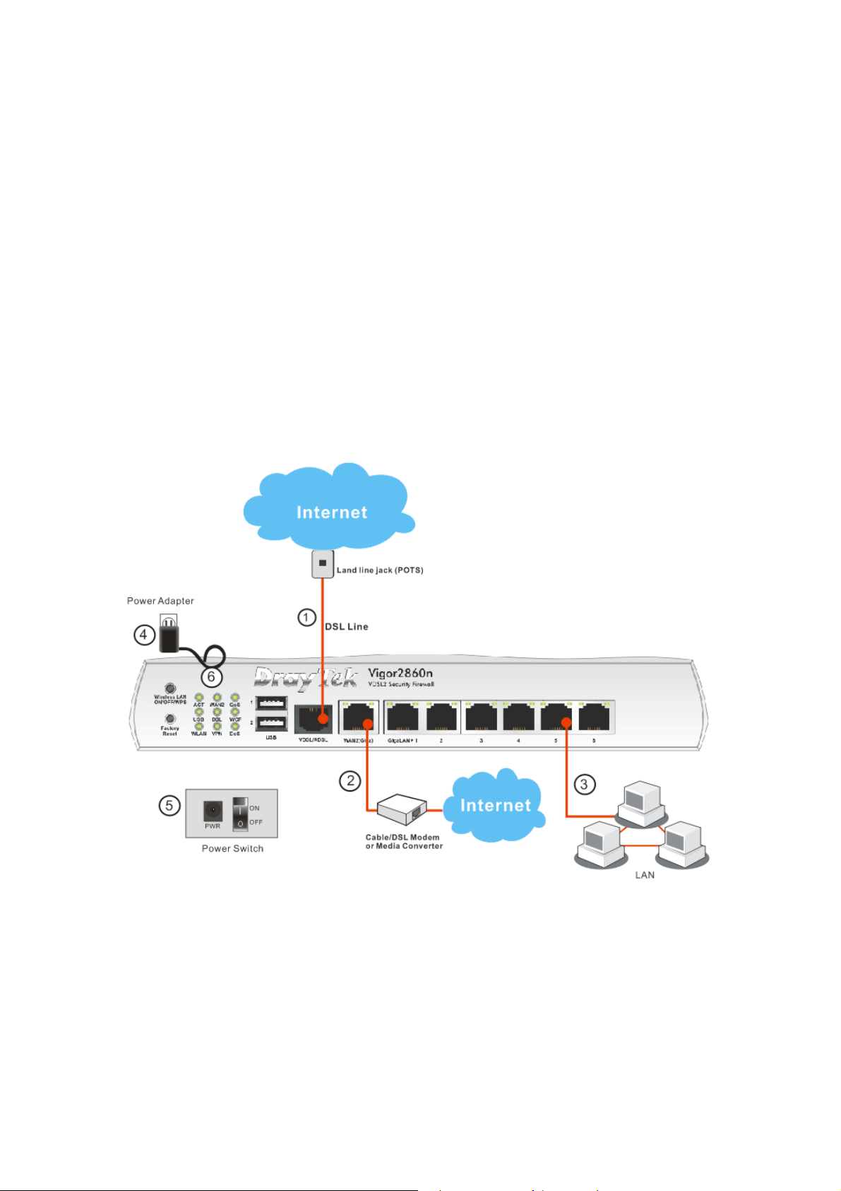
11..33 HHaarrddwwaarree IInnssttaallllaattiioonn
Before starting to configure the router, you have to connect your devices correctly.
1. Connect the DSL interface to the land line jack with a DSL line cable.
2. Connect the cable Modem/DSL Modem/Media Converter to the WAN port of router
with Ethernet cable (RJ-45).
3. Connect one end of an Ethernet cable (RJ-45) to one of the LAN ports of the router and
the other end of the cable (RJ-45) into the Ethernet port on your computer.
4. Connect one end of the power adapter to the router’s power port on the rear panel, and
the other side into a wall outlet.
5. Power on the device by pressing down the power switch on the rear panel.
6. The system starts to initiate. After completing the system test, the ACT LED will light
up and start blinking.
11..33..11 PPoossssiibbllee IInnssttaallllaattiioonn ffoorr VViiggoorr22886600nn
Vigor2860 Series User’s Guide
10
Page 25
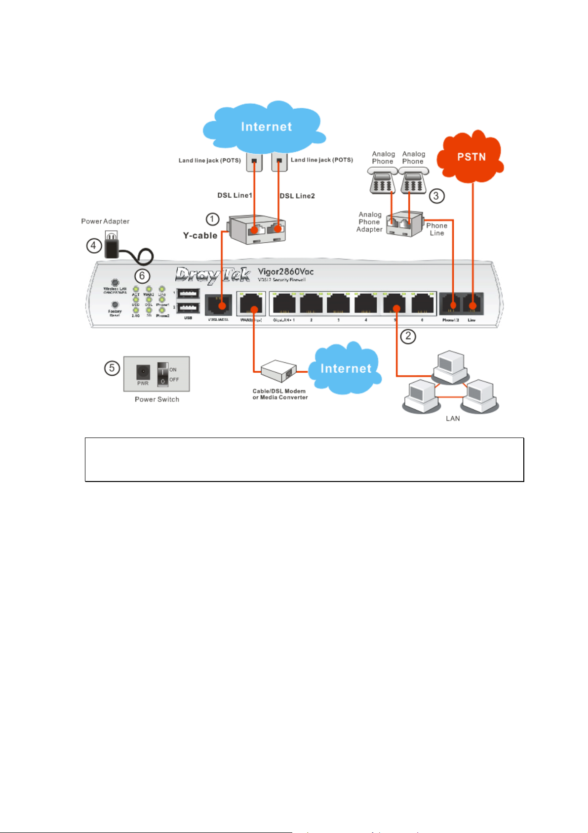
11..33..22 PPoossssiibbllee IInnssttaallllaattiioonn ffoorr VViiggoorr22886600VVaacc
Note: Due to the US Patent No. 7,127,048, the DSL and VoIP applications on
Vigor2860Vn plus and Vigor2860Vac can not be allowed to promote and to sell in the
USA.
11
Vigor2860 Series User’s Guide
Page 26
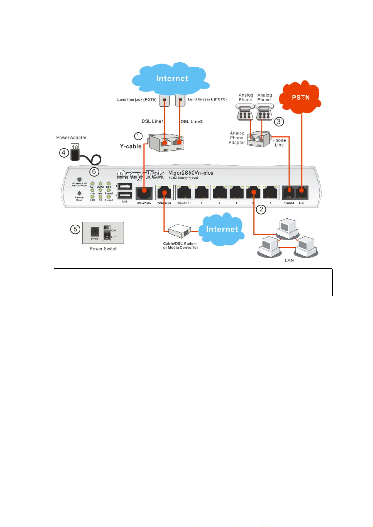
11..33..33 PPoossssiibbllee IInnssttaallllaattiioonn ffoorr VViiggoorr22886600VVnn--PPlluuss
Note: Due to the US Patent No. 7,127,048, the DSL and VoIP applications on
Vigor2860Vn plus and Vigor2860Vac can not be allowed to promote and to sell in the
USA.
Vigor2860 Series User’s Guide
12
Page 27
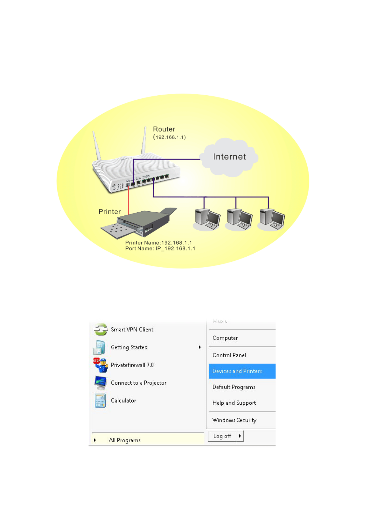
11..44 PPrriinntteerr IInnssttaallllaattiioonn
You can install a printer onto the router for sharing printing. All the PCs connected this router
can print documents via the router. The example provided here is made based on Windows 7.
For other Windows system, please visit www.DrayTek.com.
Before using it, please follow the steps below to configure settings for connected computers
(or wireless clients).
1. Connect the printer with the router through USB/parallel port.
2. Open All Programs>>Getting Started>>Devices and Printers.
13
Vigor2860 Series User’s Guide
Page 28
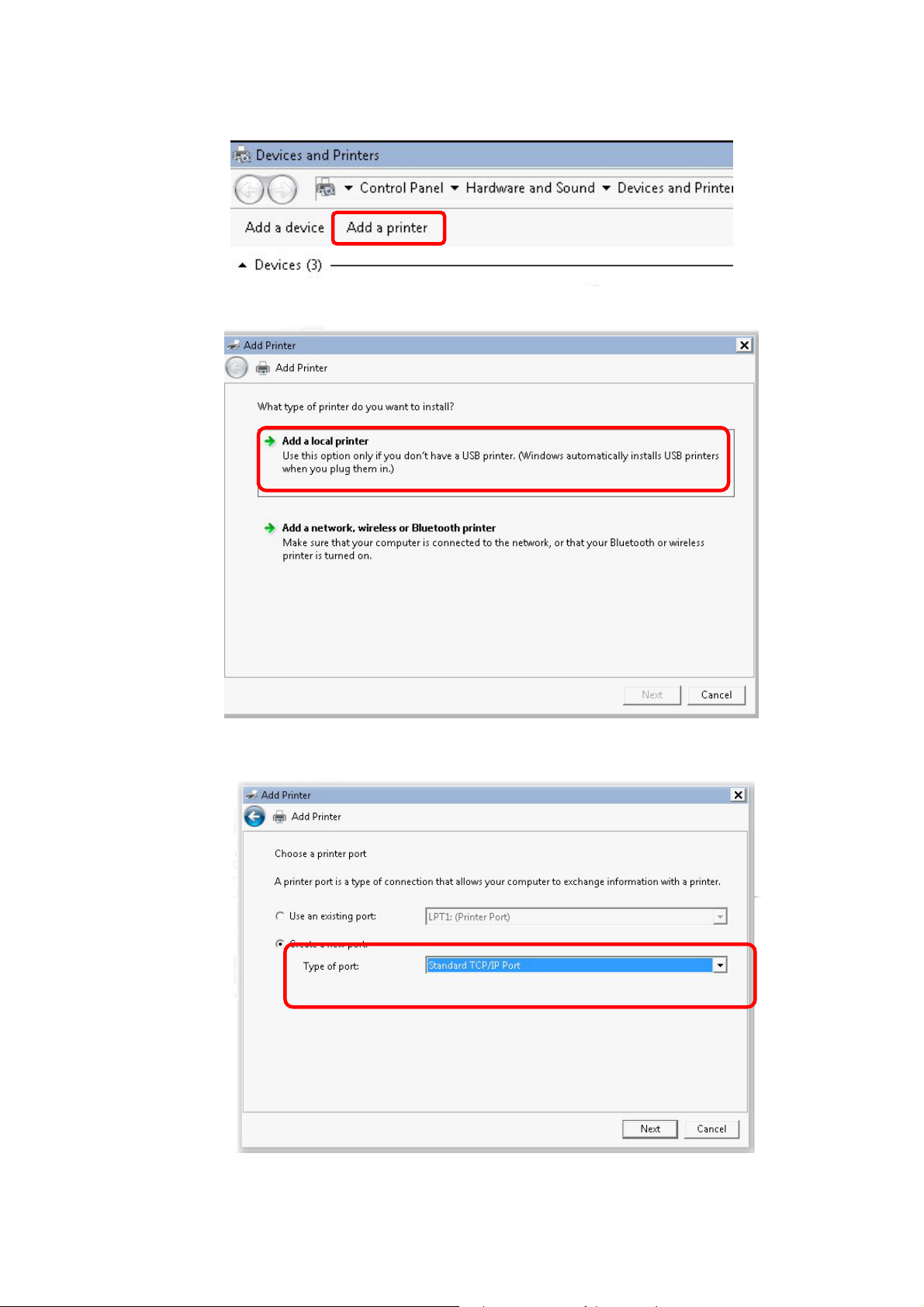
3. Click Add a printer.
4. A dialog will appear. Click Add a local printer and click Next.
5. In this dialog, choose Create a new port. In the field of Type of port, use the drop
down list to select Standard TCP/IP Port. Then, click Next.
Vigor2860 Series User’s Guide
14
Page 29
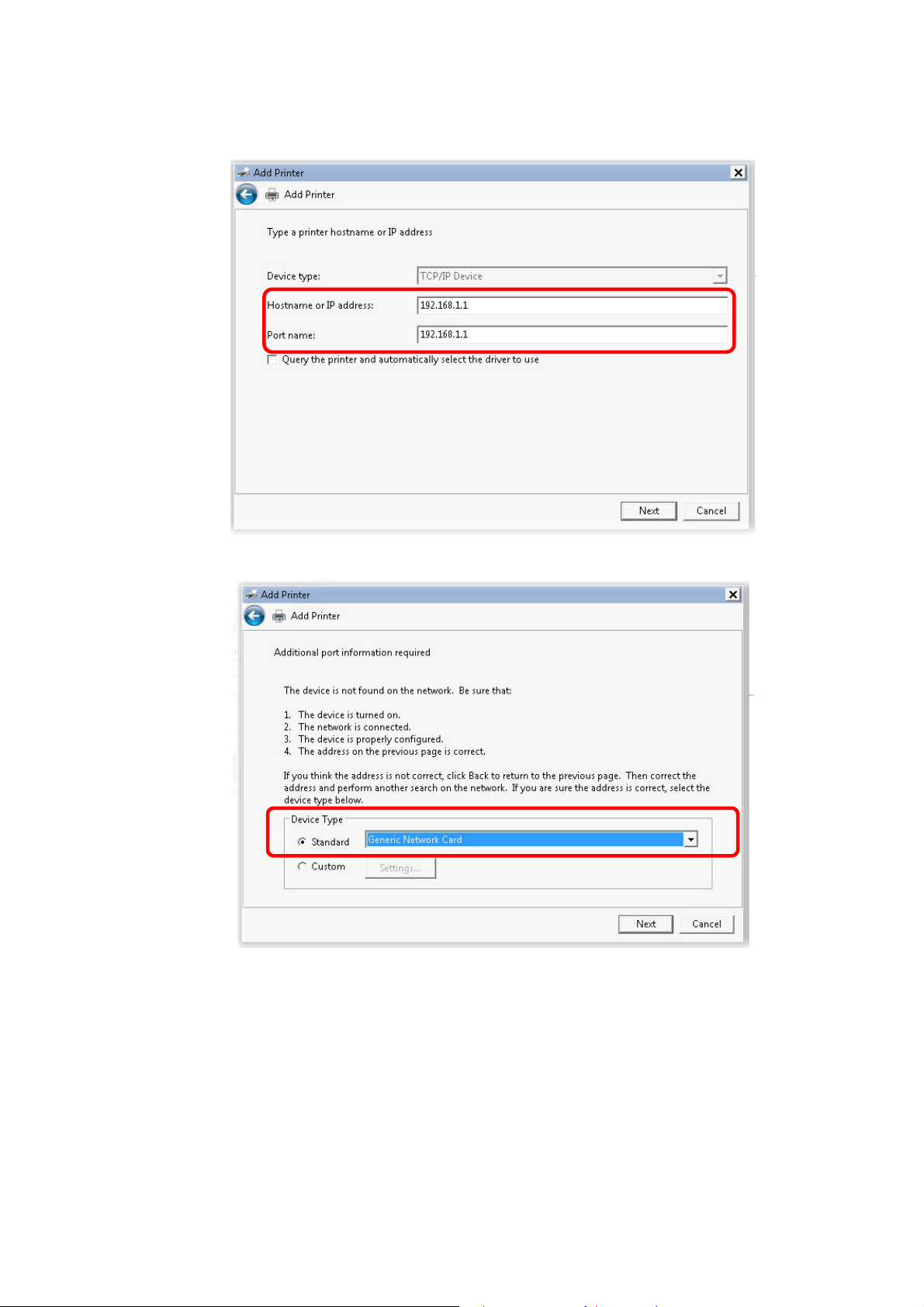
6. In the following dialog, type 192.168.1.1 (router’s LAN IP) in the field of Hostname or
IP Address and type 192.168.1.1 as the Port name. Then, click Next.
7. Click Standard and choose Generic Network Card.
15
Vigor2860 Series User’s Guide
Page 30
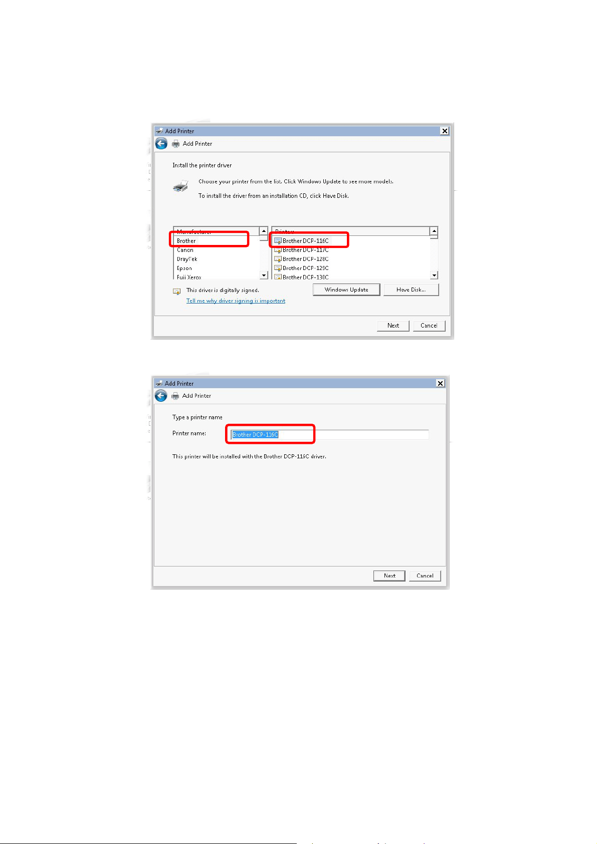
8. Now, your system will ask you to choose right name of the printer that you installed onto
the router. Such step can make correct driver loaded onto your PC. When you finish the
selection, click Next.
9. Type a name for the chosen printer. Click Next.
Vigor2860 Series User’s Guide
16
Page 31

10. Choose Do not share this printer and click Next.
11. Then, in the following dialog, click Finish.
17
Vigor2860 Series User’s Guide
Page 32

12. The new printer has been added and displayed under Printers and Faxes. Click the new
printer icon and click Printer server properties.
13. Edit the property of the new printer you have added by clicking Configure Port.
Vigor2860 Series User’s Guide
18
Page 33

14. Select "LPR" on Protocol, type p1 (number 1) as Queue Name. Then click OK. Next
please refer to the red rectangle for choosing the correct protocol and LPR name.
The printer can be used for printing now. Most of the printers with different manufacturers are
compatible with vigor router.
Note 1: Some printers with the fax/scanning or other additional functions are not supported.
If you do not know whether your printer is supported or not, please visit www.draytek.com
to find out the printer list. Open Support >FAQ/Application Notes; find out the link of
USB>>Printer Server and click it.
19
Vigor2860 Series User’s Guide
Page 34

Then, click the What types of printers are compatible with Vigor router? link.
Note 2: Vigor router supports printing request from computers via LAN ports but not WAN
port.
Vigor2860 Series User’s Guide
20
Page 35

11..55 AAcccceessssiinngg WWeebb PPaaggee
1. Make sure your PC connects to the router correctly.
You may either simply set up your computer to get IP dynamically from the router or set
up the IP address of the computer to be the same subnet as the default IP address of
Vigor router 192.168.1.1. For the detailed information, please refer to the later section Trouble Shooting of the guide.
2. Open a web browser on your PC and type http://192.168.1.1. The following window
will be open to ask for username and password.
3. Please type “admin/admin” as the Username/Password and click Login.
Notice: If you fail to access to the web configuration, please go to “Trouble
Shooting” for detecting and solving your problem.
21
Vigor2860 Series User’s Guide
Page 36

4. Now, the Main Screen will appear.
Note: The home page will be different slightly in accordance with the type of the
router you have.
5. The web page can be logged out according to the chosen condition. The default setting is
Auto Logout, which means the web configuration system will logout after 5 minutes
without any operation. Change the setting for your necessity.
11..66 CChhaannggiinngg PPaasssswwoorrdd
Please change the password for the original security of the router.
1. Open a web browser on your PC and type http://192.168.1.1. A pop-up window will
open to ask for username and password.
2. Please type “admin/admin” as Username/Password for accessing into the web user
interface with admin mode.
3. Go to System Maintenance page and choose Administrator Password.
Vigor2860 Series User’s Guide
22
Page 37

4. Enter the login password (the default is “admin”) on the field of Old Password. Type
New Password and Confirm Password. Then click OK to continue.
Note: The maximum length of the password you can set is 23 characters.
5. Now, the password has been changed. Next time, use the new password to access the
Web user interface for this router.
Note: Even the password is changed, the Username for logging onto the web user
interface is still “admin”.
23
Vigor2860 Series User’s Guide
Page 38

11..77 IInnttrroodduucciinngg DDaasshhbbooaarrdd
Dashboard shows the connection status including System Information, IPv4 Internet Access,
IPv6 Internet Access, Interface (physical connection), Security and Quick Access.
Click Dashboard from the main menu on the left side of the main page.
A web page with default selections will be displayed on the screen. Refer to the following
figure:
11..77..11 VViirrttuuaall PPaanneell
On the top of the Dashboard, a virtual panel (simulating the physical panel of the router)
displays the physical interface connection. It will be refreshed every five seconds. When you
move and click the mouse cursor on LEDs (except ACT), USB ports, VDSL/ADSL, WAN2,
or LAN1 – LAN6, related web setting page will be open for you to configure if required.
For detailed information about the LED display, refer to 1.2 LED Indicators and
Connectors.
Vigor2860 Series User’s Guide
24
Page 39

11..77..22 NNaammee wwiitthh aa LLiinnkk
A name with a link (e.g., Router Name, Current Time, WAN1~4 and etc.) below means you
can click it to open the configuration page for modification.
11..77..33 QQuuiicckk AAcccceessss ffoorr CCoommmmoonn UUsseedd MMeennuu
All the menu items can be accessed and arranged orderly on the left side of the main page for
your request. However, some important and common used menu items which can be
accessed in a quick way just for convenience.
Look at the right side of the Dashboard. You will find a group of common used functions
grouped under Quick Access.
The function links of System Status, Dynamic DDNS, TR-069, User Management, IM/P2P
Block, Schedule, Syslog/Mail Alert, LDAP, RADIUS, Firewall Object Setting and Data Flow
Monitor are displayed here. Move your mouse cursor on any one of the links and click on it.
The corresponding setting page will be open immediately.
In addition, quick access for VPN security settings such as Remote Dial-in User and LAN to
LAN are located on the bottom of this page. Scroll down the page to find them and use them if
required.
25
Vigor2860 Series User’s Guide
Page 40

Note that there is a plus (
) icon located on the left side of VPN/LAN. Click it to review the
VPN connection(s) used presently.
Host connected physically to the router via LAN port(s) will be displayed with green circles in
the field of Connected.
All of the hosts (including wireless clients) displayed with Host ID, IP Address and MAC
address indicates that the traffic would be transmitted through LAN port(s) and then the WAN
port. The purpose is to perform the traffic monitor of the host(s).
Vigor2860 Series User’s Guide
26
Page 41

11..77..44 GGUUII MMaapp
All the functions the router supports are listed with table clearly in this page. Users can click
the function link to access into the setting page of the function for detailed configuration.
Click the icon on the top of the main screen to display all the functions.
27
Vigor2860 Series User’s Guide
Page 42

11..77..55 WWeebb CCoonnssoollee
It is not necessary to use the telnet command via DOS prompt. The changes made by using
web console have the same effects as modified through web user interface. The
functions/settings modified under Web Console also can be reviewed on the web user
interface.
Click the Web Console icon on the top of the main screen to open the following screen.
Vigor2860 Series User’s Guide
28
Page 43

11..77..66 CCoonnffiigg BBaacckkuupp
There is one way to store current used settings quickly by clicking the Config Backup icon. It
allows you to backup current settings as a file. Such configuration file can be restored by using
System Maintenance>>Configuration Backup.
Simply click the icon on the top of the main screen and a pop up dialog will appear.
Click Save to store the setting.
11..77..77 LLooggoouutt
Click this icon to exit the web user interface.
11..88 OOnnlliinnee SSttaattuuss
11..88..11 PPhhyyssiiccaall CCoonnnneeccttiioonn
Such page displays the physical connection status such as LAN connection status, WAN
connection status, ADSL information, and so on.
29
Vigor2860 Series User’s Guide
Page 44

PPhhyyssiiccaall CCoonnnneeccttiioonn ffoorr IIPPvv44 PPrroottooccooll
PPhhyyssiiccaall CCoonnnneeccttiioonn ffoorr IIPPvv66 PPrroottooccooll
Vigor2860 Series User’s Guide
30
Page 45

Detailed explanation (for IPv4) is shown below:
Item Description
LAN Status
WAN1/WAN2/WAN3
/WAN4 Status
Primary DNS-Displays the primary DNS server address
for WAN interface.
Secondary DNS -Displays the secondary DNS server
address for WAN interface.
IP Address-Displays the IP address of the LAN interface.
TX Packets-Displays the total transmitted packets at the
LAN interface.
RX Packets-Displays the total received packets at the LAN
interface.
Enable – Yes in red means such interface is available but
not enabled. Yes in green means such interface is enabled.
Line – Displays the physical connection (VDSL, ADSL,
Ethernet, or USB) of this interface.
Name – Display the name of the router.
Mode - Displays the type of WAN connection (e.g.,
PPPoE).
Up Time - Displays the total uptime of the interface.
IP - Displays the IP address of the WAN interface.
GW IP - Displays the IP address of the default gateway.
TX Packets - Displays the total transmitted packets at the
WAN interface.
TX Rate - Displays the speed of transmitted octets at the
WAN interface.
RX Packets - Displays the total number of received packets
at the WAN interface.
RX Rate - Displays the speed of received octets at the
WAN interface.
Detailed explanation (for IPv6) is shown below:
Item Description
LAN Status
IP Address- Displays the IPv6 address of the LAN
interface..
TX Packets-Displays the total transmitted packets at the
LAN interface.
RX Packets-Displays the total received packets at the LAN
interface.
TX Bytes - Displays the speed of transmitted octets at the
LAN interface.
RX Bytes - Displays the speed of received octets at the
LAN interface.
WAN IPv6 Status
Enable – No in red means such interface is available but
not enabled. Yes in green means such interface is enabled.
No in red means such interface is not available.
31
Vigor2860 Series User’s Guide
Page 46

Item Description
Mode - Displays the type of WAN connection (e.g., TSPC).
Up Time - Displays the total uptime of the interface.
IP - Displays the IP address of the WAN interface.
Gateway IP - Displays the IP address of the default
gateway.
Note: The words in green mean that the WAN connection of that interface is ready for
accessing Internet; the words in red mean that the WAN connection of that interface is not
ready for accessing Internet.
11..88..22 VViirrttuuaall WWAANN
Such page displays the virtual WAN connection information.
Virtual WAN are used by TR-069 management, VoIP service and so on.
The field of Application will list the purpose of such WAN connection.
11..99 SSaavviinngg CCoonnffiigguurraattiioonn
Each time you click OK on the web page for saving the configuration, you can find messages
showing the system interaction with you.
Ready indicates the system is ready for you to input settings.
Settings Saved means your settings are saved once you click Finish or OK button.
Vigor2860 Series User’s Guide
32
Page 47

This page is left blank.
33
Vigor2860 Series User’s Guide
Page 48

Quuiicckk
Q
There are several setup wizards offered for you to configure the router simply and quickly.
Quick Start Wizard – used for building network connection, Internet access.
Service Activation Wizard – used for activating the web content filter service.
VPN Client Wizard – used for establishing VPN tunnel; the router is treated as a VPN
client.
VPN Server Wizard – used for establishing VPN tunnel; the router is treated as a VPN
server.
Wireless Wizard – used for building wireless LAN connection.
Seettuupp
S
VoIP Wizard – used for establishing VoIP profile.
22..11 QQuuiicckk SSttaarrtt WWiizzaarrdd
Quick Start Wizard can help you to deploy and use the router easily and quickly. The first screen of Quick Start Wizard is entering login password. After typing the password, please click Next.
Vigor2860 Series User’s Guide
34
Page 49

On the next page as shown below, please select the WAN interface that you use. If DSL
interface is used, please choose WAN1; if Ethernet interface is used, please choose WAN2; if
3G USB modem is used, please choose WAN3 or WAN4. Then click Next for next step.
WAN1, WAN2, WAN3 and WAN4 will bring up different configuration page. Refer to the
following sections for detailed information.
35
Vigor2860 Series User’s Guide
Page 50

22..11..11 FFoorr WWAANN11 ((AADDSSLL//VVDDSSLL22))
WAN1 is specified for ADSL or VDSL2 connection.
Available settings are explained as follows:
Item Description
Display Name
DSL Mode
Type a name to identify such WAN.
Specify the physical mode (VDSL2 only or ADSL only) for
such router manually.
VLAN Tag insertion
(VDSL2)/(ADSL)
The settings configured in this field are available for WAN1
and WAN2.
Enable – Enable the function of VLAN with tag.
The router will add specific VLAN number to all packets on
the WAN while sending them out.
Please type the tag value and specify the priority for the
packets sending by WAN1.
Disable – Disable the function of VLAN with tag.
Tag value – Type the value as the VLAN ID number. The
range is from 0 to 4095.
Priority – Type the packet priority number for such VLAN.
The range is from 0 to 7.
You have to select the appropriate Internet access type according to the information from
your ISP. For example, you should select PPPoE mode if the ISP provides you PPPoE
interface. In addition, the field of For ADSL Only will be available only when ADSL is
detected. Then click Next for next step.
Vigor2860 Series User’s Guide
36
Page 51

PPPPPPooEE//PPPPPPooAA
1. Choose WAN1 as WAN Interface and click the Next button; you will get the following
page.
Available settings are explained as follows:
Item Description
Protocol
There are two modes offered for you to choose for WAN1
interface.
Choose PPPoE/PPPoA as the protocol.
For ADSL Only
Such field is provided for ADSL only. You have to choose
encapsulation and type the values for VPI and VCI. Or, click
Auto detect to find out the best values.
Fixed IP
Click Yes to enable Fixed IP feature.
IP Address
Subnet Mask
Default Gateway
Primary DNS
Type the IP address if Fixed IP is enabled.
Type the subnet mask.
Type the IP address as the default gateway.
Type in the primary IP address for the router.
37
Vigor2860 Series User’s Guide
Page 52

Secondary DNS
Back
Next
Cancel
Type in secondary IP address for necessity in the future.
Click it to return to previous setting page.
Click it to get into the next setting page.
Click it to give up the quick start wizard.
2. After finished the above settings, simply click Next. Manually enter the
Username/Password provided by your ISP
Available settings are explained as follows:
Item Description
Service Name
Enter the description of the specific network service.
(Optional)
Username
Assign a specific valid user name provided by the ISP.
Note: The maximum length of the user name you can set is
63 characters.
Password
Assign a valid password provided by the ISP.
Note: The maximum length of the password you can set is 62
characters.
Confirm Password
Back
Next
Cancel
Retype the password.
Click it to return to previous setting page.
Click it to get into the next setting page.
Click it to give up the quick start wizard.
Vigor2860 Series User’s Guide
38
Page 53

3. After finished the above settings, click Next for viewing summary of such connection.
4. Click Finish. A page of Quick Start Wizard Setup OK!!! will appear. Then, the system
status of this protocol will be shown.
5. Now, you can enjoy surfing on the Internet.
39
Vigor2860 Series User’s Guide
Page 54

MMPPooAA // SSttaattiicc oorr DDyynnaammiicc IIPP
1. Choose WAN1 as WAN Interface and click the Next button; you will get the following
page.
Available settings are explained as follows:
Item Description
Protocol
There are two modes offered for you to choose for WAN1
interface.
Choose MPoA / Static or Dynamic IP as the protocol.
For ADSL Only
Such field is provided for ADSL only. You have to choose
encapsulation and type the values for VPI and VCI. Or, click
Auto detect to find out the best values.
Fixed IP
IP Address
Subnet Mask
Vigor2860 Series User’s Guide
Click Yes to enable Fixed IP feature.
Type the IP address if Fixed IP is enabled.
Type the subnet mask.
40
Page 55

Default Gateway
Primary DNS
Secondary DNS
Back
Next
Cancel
Type the IP address as the default gateway.
Type in the primary IP address for the router.
Type in secondary IP address for necessity in the future.
Click it to return to previous setting page.
Click it to get into the next setting page.
Click it to give up the quick start wizard.
2. Please type in the IP address/mask/gateway information originally provided by your ISP.
Then click Next for viewing summary of such connection.
3. Click Finish. A page of Quick Start Wizard Setup OK!!! will appear. Then, the system
status of this protocol will be shown.
4. Now, you can enjoy surfing on the Internet.
41
Vigor2860 Series User’s Guide
Page 56

22..11..22 FFoorr WWAANN22 ((EEtthheerrnneett))
WAN2 is dedicated to physical mode in Ethernet. If you choose WAN2, please specify
physical type. Then, click Next.
Available settings are explained as follows:
Item Description
Display Name
VLAN Tag insertion
Type a name for the router.
The settings configured in this field are available for WAN1
and WAN2.
Enable – Enable the function of VLAN with tag.
The router will add specific VLAN number to all packets on
the WAN while sending them out.
Please type the tag value and specify the priority for the
packets sending by WAN1.
Disable – Disable the function of VLAN with tag.
Tag value – Type the value as the VLAN ID number. The
range is form 0 to 4095.
Priority – Type the packet priority number for such VLAN.
The range is from 0 to 7.
On the next page as shown below, please select the appropriate Internet access type according
to the information from your ISP. For example, you should select PPPoE mode if the ISP
provides you PPPoE interface. Then click Next for next step.
Vigor2860 Series User’s Guide
42
Page 57

PPPPPPooEE
1. Choose WAN2 as the WAN Interface and click the Next button. The following page will
be open for you to specify Internet Access Type.
2. Click PPPoE as the Internet Access Type. Then click Next to continue.
Available settings are explained as follows:
Item Description
Service Name
Enter the description of the specific network service.
(Optional)
Username
Assign a specific valid user name provided by the ISP.
Note: The maximum length of the user name you can set is
63 characters.
Password
Assign a valid password provided by the ISP.
Note: The maximum length of the password you can set is 62
43
Vigor2860 Series User’s Guide
Page 58

Item Description
characters.
Confirm Password
Back
Next
Cancel
Retype the password.
Click it to return to previous setting page.
Click it to get into the next setting page.
Click it to give up the quick start wizard.
3. Please manually enter the Username/Password provided by your ISP. Click Next for
viewing summary of such connection.
4. Click Finish. A page of Quick Start Wizard Setup OK!!! will appear. Then, the system
status of this protocol will be shown.
5. Now, you can enjoy surfing on the Internet.
Vigor2860 Series User’s Guide
44
Page 59

PPPPTTPP//LL22TTPP
1. Choose WAN2 as the WAN Interface and click the Next button. The following page will
be open for you to specify Internet Access Type.
2. Click PPTP/L2TP as the Internet Access Type. Then click Next to continue.
Available settings are explained as follows:
Item Description
User Name
Assign a specific valid user name provided by the ISP.
Note: The maximum length of the user name you can set is
63 characters.
Password
Assign a valid password provided by the ISP.
45
Vigor2860 Series User’s Guide
Page 60

Note: The maximum length of the password you can set is 62
characters.
Confirm Password
WAN IP
Configuration
Retype the password.
Obtain an IP address automatically – the router will get an
IP address automatically from DHCP server.
Specify an IP address – you have to type relational settings
manually.
IP Address - Type the IP address.
Subnet Mask –Type the subnet mask.
Gateway – Type the IP address of the gateway.
Primary DNS –Type in the primary IP address for the router.
Second DNS –Type in secondary IP address for necessity in
the future.
PPTP Server / L2TP
Type the IP address of the server.
Server
Back
Next
Cancel
Click it to return to previous setting page.
Click it to get into the next setting page.
Click it to give up the quick start wizard.
3. Please type in the IP address/mask/gateway information originally provided by your ISP.
Then click Next for viewing summary of such connection.
4. Click Finish. A page of Quick Start Wizard Setup OK!!! will appear. Then, the system
status of this protocol will be shown.
5. Now, you can enjoy surfing on the Internet.
Vigor2860 Series User’s Guide
46
Page 61

SSttaattiicc IIPP
1. Choose WAN2 as the WAN Interface and click the Next button. The following page will
be open for you to specify Internet Access Type.
2. Click Static IP as the Internet Access type. Simply click Next to continue.
Available settings are explained as follows:
Item Description
WAN IP
Subnet Mask
Gateway
Primary DNS
Secondary DNS
Back
Type the IP address.
Type the subnet mask.
Type the IP address of gateway.
Type in the primary IP address for the router.
Type in secondary IP address for necessity in the future.
Click it to return to previous setting page.
47
Vigor2860 Series User’s Guide
Page 62

Next
Cancel
Click it to get into the next setting page.
Click it to give up the quick start wizard.
3. Please type in the IP address information originally provided by your ISP. Then click
Next for next step.
4. Click Finish. A page of Quick Start Wizard Setup OK!!! will appear. Then, the system
status of this protocol will be shown.
5. Now, you can enjoy surfing on the Internet.
DDHHCCPP
1. Choose WAN2 as WAN Interface and click the Next button. The following page will be
open for you to specify Internet Access Type.
Vigor2860 Series User’s Guide
48
Page 63

2. Click DHCP as the Internet Access type. Simply click Next to continue.
Available settings are explained as follows:
Item Description
Host Name
Type the name of the host.
Note: The maximum length of the host name you can set is
39 characters.
MAC
Some Cable service providers specify a specific MAC
address for access authentication. In such cases you need to
enter the MAC address.
Back
Next
Cancel
Click it to return to previous setting page.
Click it to get into the next setting page.
Click it to give up the quick start wizard.
3. After finished the settings above, click Next for viewing summary of such connection.
49
Vigor2860 Series User’s Guide
Page 64

4. Click Finish. A page of Quick Start Wizard Setup OK!!! will appear. Then, the system
status of this protocol will be shown.
5. Now, you can enjoy surfing on the Internet.
Vigor2860 Series User’s Guide
50
Page 65

22..11..33 FFoorr WWAANN33//WWAANN44 ((UUSSBB))
WAN3/WAN4 is dedicated to physical mode in USB.
1. Choose WAN3/WAN4 as WAN Interface.
2. Then, click Next for getting the following page.
Available settings are explained as follows:
Item Description
Internet Access
Choose one of the selections as the protocol of accessing the
internet.
3G/4G USB Modem
(PPP mode)
SIM Pin code –Type PIN code of the SIM card that will be
used to access Internet. The maximum length of the pin code
you can set is 15 characters.
Modem Initial String – Such value is used to initialize USB
modem. Please use the default value. If you have any
51
Vigor2860 Series User’s Guide
Page 66

question, please contact to your ISP. The maximum length of
the string you can set is 47 characters.
APN Name – APN means Access Point Name which is
provided and required by some ISPs. Type the name and
click Apply.
4G USB Modem
(DHCP mode)
SIM Pin code –Type PIN code of the SIM card that will be
used to access Internet.
Network Mode – Force Vigor router to connect Internet with
the mode specified here. If you choose 4G/3G/2G as network
mode, the router will choose a suitable one according to the
actual wireless signal automatically.
APN Name – APN means Access Point Name which is
provided and required by some ISPs.
Note: Such mode is supported by WAN3 only.
3. Then, click Next for viewing summary of such connection.
4. Click Finish. A page of Quick Start Wizard Setup OK!!! will appear. Then, the system
status of this protocol will be shown.
5. Now, you can enjoy surfing on the Internet.
Vigor2860 Series User’s Guide
52
Page 67

22..22 SSeerrvviiccee AAccttiivvaattiioonn WWiizzaarrdd
Service Activation Wizard can guide you to activate WCF service (Web Content Filter) with a
quick and easy way. For the Service Activation Wizard is only available for admin
operation, therefore, please type “admin/admin” on Username/Password while Logging
into the web user interface.
Service Activation Wizard is a tool which allows you to use trial version of WCF directly
without accessing into the server (MyVigor) located on http://myvigor.draytek.com. For using
Web Content Filter Profile, please refer to later section Web Content Filter Profile for
detailed information.
Now, follow the steps listed below to activate WCF feature for your router.
Note: Such function is available only for Admin Mode.
1. Open Wizards>>Service Activation Wizard.
2. The screen of Service Activation Wizard will be shown as follows. Click Next to
activate free trail edition.
Free trial edition: it offers a period of trial for you to get acquainted with WCF function.
53
Vigor2860 Series User’s Guide
Page 68

3. In the following page, you can activate the Web content filter services at the same time
or individually. When you finish the selection, please click Next.
Commtouch is the web content filter based on Commtouch operated in the
worldwide. There is a 30-day trial period. After trial, you can purchase DrayTek's
prepared Commtouch GlobalView WCF package from retailing outlets. In addition,
Commtouch is merged by Cyren, and GlobalView services will be continued to
deliver powerful cloud-based information security solutions! Refer to:
http://www.prnewswire.com/news-releases/commtouch-is-now-cyren-239025151.ht
ml
BPjM is WCF for German Speaking users. The fragfINN is whitelist for German
Speaking users. The BPjM is ideal for your family to provide more Internet security
for youngsters.
4. Setting confirmation page will be displayed as follows, please click Next.
Vigor2860 Series User’s Guide
54
Page 69

5. Wait for a moment till the following page appears.
When such page appears, you can enable or disable these services for your necessity.
Then, click Finish.
Note: The service will be activated and applied as the default rule configured in
Firewall>>General Setup.
6. Now, the web page will display the service that you have activated according to your
selection(s). The valid time for the free trial of these services is one month.
When all the trial editions for various web content filters had been enabled, the
configuration page of Service Activation Wizard will be invalid as shown below.
55
Vigor2860 Series User’s Guide
Page 70

22..33 VVPPNN CClliieenntt WWiizzaarrdd
Such wizard is used to configure VPN settings for VPN client. Such wizard will guide to set
the LAN-to-LAN profile for VPN dial out connection (from server to client) step by step.
1. Open VPN and Remote Access>>VPN Client Wizard. The following page will appear.
Available settings are explained as follows:
Item Description
LAN-to-LAN Client
Mode Selection
Please choose a
LAN-to-LAN Profile
Choose the client mode.
Route Mode/NAT Mode – If the remote network only
allows you to dial in with single IP, please choose NAT
mode, otherwise please choose Route Mode.
There are 32 VPN profiles for users to set.
Vigor2860 Series User’s Guide
56
Page 71

2. When you finish the mode and profile selection, please click Next to open the following
page.
In this page, you have to select suitable VPN type for the VPN client profile. There are
six types provided here. Different type will lead to different configuration page. After
making the choices for the client profile, please click Next. You will see different
configurations based on the selection(s) you made.
57
Vigor2860 Series User’s Guide
Page 72

Note: The following descriptions for VPN Type are based on the Route Mode
specified in LAN-to-LAN Client Mode Selection.
When you choose PPTP (None Encryption) or PPTP (Encryption), you will see the
following graphic:
When you choose IPsec, you will see the following graphic:
When you choose L2TP, you will see the following graphic:
Vigor2860 Series User’s Guide
58
Page 73

When you choose L2TP over IPsec (Nice to Have) or L2TP over IPsec (Must), you
will see the following graphic:
Available settings are explained as follows:
Item Description
Profile Name
Type a name for such profile. The length of the file is
limited to 10 characters.
59
Vigor2860 Series User’s Guide
Page 74

VPN Dial-Out
Through
Use the drop down menu to choose a proper WAN interface
for this profile. This setting is useful for dial-out only.
WAN1 First/ WAN2 First /WAN3 First/WAN4 First-
While connecting, the router will use
WAN1/WAN2/WAN3/WAN4 as the first channel for VPN
connection. If WAN1/WAN2/WAN3/WAN4 fails, the
router will use another WAN interface instead.
WAN1 Only /WAN2 Only/WAN3 Only/WAN4 Only -
While connecting, the router will use
WAN1/WAN2/WAN3 as the only channel for VPN
connection.
WAN1 Only: Only establish VPN if WAN2 down - If
WAN2 failed, the router will use WAN1 for VPN
connection.
WAN2 Only: Only establish VPN if WAN1 down - If
WAN1 failed, the router will use WAN2 for VPN
connection.
Always On
Server IP/Host Name
for VPN
IKE Authentication
Method
Digital Signature
(X.509)
IPsec Security
Method
Check to enable router always keep VPN connection.
Type the IP address of the server or type the host name for
such VPN profile.
IKE Authentication Method usually applies to those are
remote dial-in user or node (LAN to LAN) which uses
dynamic IP address and IPsec-related VPN connections
such as L2TP over IPsec and IPsec tunnel.
Pre-Shared Key- Specify a key for IKE authentication.
Confirm Pre-Shared Key-Confirm the pre-shared key.
Click Digital Signature to invoke this function.
Peer ID – Choose the peer ID selection from the drop down
list.
Local ID – Choose Alternative Subject Name First or
Subject Name First.
Local Certificate – Use the drop down list to choose one of
the certificates for using. You have to configure one
certificate at least previously in Certificate Management
>> Local Certificate. Otherwise, the setting you choose
here will not be effective.
Medium - Authentication Header (AH) means data will be
authenticated, but not be encrypted. By default, this option
Vigor2860 Series User’s Guide
60
Page 75

is active.
High - Encapsulating Security Payload (ESP) means
payload (data) will be encrypted and authenticated. You
may select encryption algorithm from Data Encryption
Standard (DES), Triple DES (3DES), and AES.
User Name
This field is used to authenticate for connection when you
select PPTP or L2TP with or without IPsec policy above.
The length of the user name is limited to 11 characters.
Password
This field is used to authenticate for connection when you
select PPTP or L2TP with or without IPsec policy above.
The length of the password is limited to 11 characters.
Remote Network IP
Please type one LAN IP address (according to the real
location of the remote host) for building VPN connection.
Remote Network
Mask
Please type the network mask (according to the real location
of the remote host) for building VPN connection.
3. After finishing the configuration, please click Next. The confirmation page will be shown
as follows. If there is no problem, you can click one of the radio buttons listed on the page
and click Finish to execute the next action.
Available settings are explained as follows:
Item Description
Go to the VPN
Connection
Management
Do another VPN
Server Wizard Setup
View more detailed
configuration
Click this radio button to access VPN and Remote
Access>>Connection Management for viewing VPN
Connection status.
Click this radio button to set another profile of VPN Server
through VPN Server Wizard.
Click this radio button to access VPN and Remote
Access>>LAN to LAN for viewing detailed configuration.
61
Vigor2860 Series User’s Guide
Page 76

22..44 VVPPNN SSeerrvveerr WWiizzaarrdd
Such wizard is used to configure VPN settings for VPN server. Such wizard will guide to set
the LAN-to-LAN profile for VPN dial in connection (from client to server) step by step.
1. Open VPN and Remote Access>>VPN Server Wizard. The following page will appear.
Available settings are explained as follows:
Item Description
VPN Server Mode
Selection
Please choose a
LAN-to-LAN Profile
Choose the direction for the VPN server.
Site to Site VPN – To set a LAN-to-LAN profile
automatically, please choose Site to Site VPN.
Remote Dial-in User –You can manage remote access by
maintaining a table of remote user profile, so that users can
be authenticated to dial-in via VPN connection.
This item is available when you choose Site to Site VPN
(LAN-to-LAN) as VPN server mode. There are 32 VPN
profiles for users to set.
Vigor2860 Series User’s Guide
62
Page 77

Please choose a
Dial-in User
Accounts
Allowed Dial-in Type
This item is available when you choose Remote Dial-in
User (Teleworker) as VPN server mode. There are 32 VPN
tunnels for users to set.
This item is available after you choose any one of dial-in
user account profiles. Next, you have to select suitable
dial-in type for the VPN server profile. There are several
types provided here (similar to VPN Client Wizard).
Different Dial-in Type will lead to different configuration
page. In addition, adjustable items for each dial-in type will
be changed according to the VPN Server Mode (Site to Site
VPN and Remote Dial-in User) selected.
2. After making the choices for the server profile, please click Next. You will see different
configurations based on the selection you made.
Here we take the examples of choosing Site-to-Site VPN as the VPN Server Mode.
63
Vigor2860 Series User’s Guide
Page 78

When you check PPTP, you will see the following graphic:
When you check PPTP & IPsec & L2TP (three types) or PPTP & IPsec (two types) or
L2TP with Policy (Nice to Have/Must), you will see the following graphic:
Vigor2860 Series User’s Guide
64
Page 79

When you check IPsec, you will see the following graphic:
Available settings are explained as follows:
Item Description
Profile Name
Type a name for such profile. The length of the file is
limited to 10 characters.
User Name
This field is used to authenticate for connection when you
select PPTP or L2TP with or without IPsec policy above.
The length of the name is limited to 11 characters.
Password
This field is used to authenticate for connection when you
select PPTP or L2TP with or without IPsec policy above.
The length of the name is limited to 11 characters.
Pre-Shared Key
For IPsec/L2TP IPsec authentication, you have to type a
pre-shared key.
The length of the name is limited to 64 characters.
Confirm Pre-Shared
Type the pre-shared key again for confirmation.
Key
Digital Signature
(X.509)
Check the box of Digital Signature to invoke this function.
Peer ID – Choose the peer ID selection from the drop down
list.
Local ID – Choose Alternative Subject Name First or
Subject Name First.
Peer IP/VPN Client
IP
Peer ID
Type the WAN IP address or VPN client IP address for the
remote client.
Type the ID name for the remote client.
The length of the name is limited to 47 characters.
65
Vigor2860 Series User’s Guide
Page 80

Remote Network IP
Please type one LAN IP address (according to the real
location of the remote host) for building VPN connection.
Remote Network
Mask
Please type the network mask (according to the real location
of the remote host) for building VPN connection.
3. After finishing the configuration, please click Next. The confirmation page will be shown
as follows. If there is no problem, you can click one of the radio buttons listed on the page
and click Finish to execute the next action.
Available settings are explained as follows:
Item Description
Go to the VPN
Connection
Management
Do another VPN
Server Wizard Setup
View more detailed
configuration
Click this radio button to access VPN and Remote
Access>>Connection Management for viewing VPN
Connection status.
Click this radio button to set another profile of VPN Server
through VPN Server Wizard.
Click this radio button to access VPN and Remote
Access>>LAN to LAN for viewing detailed configuration.
Vigor2860 Series User’s Guide
66
Page 81

22..55 WWiirreelleessss WWiizzaarrdd
The wireless wizard allows you to configure settings specified for a host AP (for home use or
internal use for a company) and specified for a guest AP (for any wireless clients accessing
into Internet).
Follow the steps listed below:
1. Open Wireless Wizard.
2. The screen of wireless wizard will be shown as follows. This page will be used for internal
users in a company or your home.
Available settings are explained as follows:
Item Description
Wireless 2.4GHz Settings
Name
Mode
Type the SSID name of this router for wireless 2.4GHz. The
default name is defined with DrayTek. Change the name if
required.
At present, the router can connect to 11n Only, 11g Only,
Mixed (11b+11g), Mixed (11a+11n), Mixed (11g+11n), and
Mixed (11b+11g+11n) stations simultaneously. Simply
choose Mix (11b+11g+11n) mode.
67
Vigor2860 Series User’s Guide
Page 82

Channel
Means the channel of frequency of the wireless LAN. The
default channel is 6. You may switch channel if the selected
channel is under serious interference. If you have no idea of
choosing the frequency, please select Auto to let system
determine for you.
Security Key
Use the same SSID
and Security Key as
above
Wireless 5GHz Settings
Name
Mode
Channel
The wireless mode offered by this wizard is WPA2/PSK.
The WPA encrypts each frame transmitted from the radio
using the key, which either PSK (Pre-Shared Key) entered
manually in this field below or automatically negotiated via
802.1x authentication.
Either 8~63 ASCII characters, such as 012345678(or 64
Hexadecimal digits leading by 0x, such as
“0x321253abcde…”).
Check the box to use the same settings configured above.
Type the SSID name of this router for wireless 5GHz..
At present, the router can connect to 11a Only, 11n Only
(5GHz), Mixed (11a+11n) and Mixed (11a+11n+11ac)
stations simultaneously.
Means the channel of frequency of the wireless LAN. The
default channel is 36. You may switch channel if the selected
channel is under serious interference. If you have no idea of
choosing the frequency, please select Auto to let system
determine for you.
Security Key
Next
Cancel
3. After typing the required information, click Next. The settings in the page limit the
wireless station (guest) accessing into Internet but not being allowed to share the LAN
network and VPN connection.
Vigor2860 Series User’s Guide
The wireless mode offered by this wizard is WPA2/PSK.
The WPA encrypts each frame transmitted from the radio
using the key, which either PSK (Pre-Shared Key) entered
manually in this field below or automatically negotiated via
802.1x authentication.
Either 8~63 ASCII characters, such as 012345678(or 64
Hexadecimal digits leading by 0x, such as
"0x321253abcde...").
Click it to get into the next setting page.
Exit the wireless wizard without saving any changes.
68
Page 83

Available settings are explained as follows:
Item Description
Wireless 2.4GHz Settings
Enable/Disable
SSID
Security Key
Click it to enable or disable settings in this page.
Type the SSID name of this router. (SSID1)
The wireless mode offered by this wizard is WPA2/PSK.
The WPA encrypts each frame transmitted from the radio
using the key, which either PSK (Pre-Shared Key) entered
manually in this field below or automatically negotiated via
802.1x authentication.
Either 8~63 ASCII characters, such as 012345678(or 64
Hexadecimal digits leading by 0x, such as
"0x321253abcde...").
Rate Control
It controls the data transmission rate through wireless
connection.
Upload – Check Enable and type the transmitting rate for
data upload. Default value is 30,000 kbps.
Download – Type the transmitting rate for data download.
Default value is 30,000 kbps.
Wireless 5GHz Settings
Enable/Disable
Use the same SSID
and Security Key as
above
SSID
Click it to enable or disable settings in this page.
Check the box to use the same settings configured above.
Type the SSID name of this router. (SSID2)
69
Vigor2860 Series User’s Guide
Page 84

Security Key
The wireless mode offered by this wizard is WPA2/PSK.
The WPA encrypts each frame transmitted from the radio
using the key, which either PSK (Pre-Shared Key) entered
manually in this field below or automatically negotiated via
802.1x authentication.
Either 8~63 ASCII characters, such as 012345678(or 64
Hexadecimal digits leading by 0x, such as
"0x321253abcde...").
Rate Control
It controls the data transmission rate through wireless
connection.
Upload – Check Enable and type the transmitting rate for
data upload. Default value is 30,000 kbps.
Download – Type the transmitting rate for data download.
Default value is 30,000 kbps.
Next
Cancel
Click it to get into the next setting page.
Exit the wireless wizard without saving any changes.
4. After typing the required information, click Next.
5. The following page will display the configuration summary for wireless setting.
6. Click Finish to complete the wireless settings configuration.
Vigor2860 Series User’s Guide
70
Page 85

22..66 VVooIIPP WWiizzaarrdd
Vigor router offers a quick method to configure settings for VoIP application. Follow the steps
listed below.
Note: This wizard is available for “V” model only.
1. Open Wizards>>VoIP Wizard.
2. The screen of VoIP Wizard will be shown as follows.
Available settings are explained as follows:
Item Description
Set VoIP service
provider domain
Set Account quickly
Next
VoIP service provider - Use the drop down list to choose
the ISP which offers the VoIP service for your router.
SIP Port – Use the default setting (5060).
Account Number/Name – Type the account number/name
registered to your ISP.
Password – Type the password for the account registered to
your ISP.
Use the same Account as phone 1 – If you don’t need to
configure Phone 2 settings, simply check this box.
Click it to get into the next setting page.
71
Vigor2860 Series User’s Guide
Page 86

Cancel
Click it to give up the VoIP wizard.
3. After finished the settings above, click Next for viewing summary of such connection.
4. Click Finish. A page of VoIP Wizard Setup OK!!! will appear.
Vigor2860 Series User’s Guide
72
Page 87

22..77 RReeggiisstteerriinngg VViiggoorr RRoouutteerr
You have finished the configuration of Quick Start Wizard and you can surf the Internet at any
time. Now it is the time to register your Vigor router to MyVigor website for getting more
service. Please follow the steps below to finish the router registration.
1 Please login the web configuration interface of Vigor router by typing “admin/admin”
as User Name / Password.
2 Click Support Area>>Production Registration from the home page.
3 A Login page will be shown on the screen. Please type the account and password that
you created previously. And click Login.
73
Vigor2860 Series User’s Guide
Page 88

Notice: If you haven’t an accessing account, please refer to section 4.9 Creating an
Account for MyVigor on User’s Guide to create your own one. Please read the
articles on the Agreement regarding user rights carefully while creating a user
account.
4 The following page will be displayed after you logging in MyVigor. From this page,
please click Add or Product Registration.
5 When the following page appears, please type in Nickname (for the router) and choose
the right registration date from the popup calendar (it appears when you click on the box
of Registration Date). After adding the basic information for the router, please click
Submit.
Vigor2860 Series User’s Guide
74
Page 89

6 When the following page appears, your router information has been added to the
database.
7 After clicking OK, you will see the following page. Your router has been registered to
myvigor website successfully.
75
Vigor2860 Series User’s Guide
Page 90

Addvvaanncceedd
A
This chapter will guide users to execute web configuration.
1. Open a web browser on your PC and type http://192.168.1.1. The window will ask for
typing username and password.
2. Please type “admin/admin” on Username/Password for administration operation.
Now, the Main Screen will appear. Note that different model will have different web pages.
Coonnffiigguurraattiioonn
C
33..11 WWAANN
33..11..11 BBaassiiccss ooff IInntteerrnneett PPrroottooccooll ((IIPP)) NNeettwwoorrkk
Vigor2860 Series User’s Guide
Quick Start Wizard offers user an easy method to quick setup the connection mode for the router. Moreover, if you want to adjust more settings for different WAN modes, please go to WAN group.
IP means Internet Protocol. Every device in an IP-based Network including routers, print
server, and host PCs, needs an IP address to identify its location on the network. To avoid
address conflicts, IP addresses are publicly registered with the Network Information Centre
(NIC). Having a unique IP address is mandatory for those devices participated in the public
network but not in the private TCP/IP local area networks (LANs), such as host PCs under the
management of a router since they do not need to be accessed by the public. Hence, the NIC
has reserved certain addresses that will never be registered publicly. These are known as
private IP addresses, and are listed in the following ranges:
From 10.0.0.0 to 10.255.255.255
From 172.16.0.0 to 172.31.255.255
From 192.168.0.0 to 192.168.255.255
76
Page 91

WWhhaatt aarree PPuubblliicc IIPP AAddddrreessss aanndd PPrriivvaattee IIPP AAddddrreessss
As the router plays a role to manage and further protect its LAN, it interconnects groups of
host PCs. Each of them has a private IP address assigned by the built-in DHCP server of the
Vigor router. The router itself will also use the default private IP address: 192.168.1.1 to
communicate with the local hosts. Meanwhile, Vigor router will communicate with other
network devices through a public IP address. When the data flow passing through, the
Network Address Translation (NAT) function of the router will dedicate to translate
public/private addresses, and the packets will be delivered to the correct host PC in the local
area network. Thus, all the host PCs can share a common Internet connection.
GGeett YYoouurr PPuubblliicc IIPP AAddddrreessss ffrroomm IISSPP
In ADSL deployment, the PPP (Point to Point)-style authentication and authorization is
required for bridging customer premises equipment (CPE). Point to Point Protocol over
Ethernet (PPPoE) connects a network of hosts via an access device to a remote access
concentrator or aggregation concentrator. This implementation provides users with significant
ease of use. Meanwhile it provides access control, billing, and type of service according to
user requirement.
When a router begins to connect to your ISP, a serial of discovery process will occur to ask for
a connection. Then a session will be created. Your user ID and password is authenticated via
PAP or CHAP with RADIUS authentication system. And your IP address, DNS server, and
other related information will usually be assigned by your ISP.
NNeettwwoorrkk CCoonnnneeccttiioonn bbyy 33GG//44GG UUSSBB MMooddeemm
For 3G/4G mobile communication through Access Point is popular more and more,
Vigor2860 adds the function of 3G/4G network connection for such purpose. By connecting
3G/4G USB Modem to the USB port of Vigor2860, it can support
LTE/HSDPA/UMTS/EDGE/GPRS/GSM and the future 3G/4G standard (HSUPA, etc).
Vigor2860n with 3G/4G USB Modem allows you to receive 3G/4G signals at any place such
as your car or certain location holding outdoor activity and share the bandwidth for using by
more people. Users can use LAN ports on the router to access Internet. Also, they can access
Internet via 802.11(a/b/g/n/ac) wireless standard, and enjoy the powerful firewall, bandwidth
management, and VPN features of Vigor2860n series.
After connecting into the router, 3G/4G USB Modem will be regarded as the WAN3/WAN4
port. However, the original WAN1 and WAN2 still can be used and Load-Balance can be
done in the router. Besides, 3G/4G USB Modem in WAN3/WAN4 also can be used as backup
device. Therefore, when WAN1 and WAN2 are not available, the router will use 3.5G for
supporting automatically. The supported 3G/4G USB Modem will be listed on DrayTek web
site. Please visit www.draytek.com for more detailed information.
Below shows the menu items for WAN.
77
Vigor2860 Series User’s Guide
Page 92

33..11..22 GGeenneerraall SSeettuupp
This section will introduce some general settings of Internet and explain the connection modes
for WAN1, WAN2 and WAN3/WAN4 in details.
This router supports multiple-WAN function. It allows users to access Internet and combine
the bandwidth of the multiple WANs to speed up the transmission through the network. Each
WAN port can connect to different ISPs, Even if the ISPs use different technology to provide
telecommunication service (such as DSL, Cable modem, etc.). If any connection problem
occurred on one of the ISP connections, all the traffic will be guided and switched to the
normal communication port for proper operation. Please configure WAN1, WAN2, WAN3
and WAN4 settings.
This webpage allows you to set general setup for WAN1, WAN2, WAN3 and WAN4
respectively. In default, WAN2 is disabled. If you want to enable it, simply click the WAN2
link and select Yes in the field of Enable.
Available settings are explained as follows:
Item Description
Load Balance Mode
Index
Vigor2860 Series User’s Guide
This option is available for multiple-WAN for getting
enough bandwidth for each WAN port. If you know the
practical bandwidth for your WAN interface, please choose
the setting of According to Line Speed. Otherwise, please
choose Auto Weight to let the router reach the best load
balance.
Click the WAN interface link under Index to access into the
WAN configuration page.
78
Page 93

Enable
V means such WAN interface is enabled and ready to be
used.
Physical Mode / Type
Display the physical mode and physical type of such WAN
interface.
Line Speed(Kbps)
DownLink/UpLink
Active Mode
Display the downstream and upstream rate of such WAN
interface.
Display whether such WAN interface is Active device or
backup device.
Backup (WAN#)- Display the backup WAN interface for
such WAN when it is disabled.
Note: In default, each WAN port is enabled.
After finished the above settings, click OK to save the settings.
WWAANN11 wwiitthh AADDSSLL//VVDDSSLL
Vigor router will detect the physical line is connected by ADSL or VDSL2 automatically.
Therefore, this page allows you to configure settings for ADSL and VDSL2 at one time. That
is, it is not necessary for you to configure different profile settings for ADSL and VDSL2
respectively.
Available settings are explained as follows:
Item Description
Enable
Choose Yes to invoke the settings for this WAN interface.
Choose No to disable the settings for this WAN interface.
79
Vigor2860 Series User’s Guide
Page 94

Display Name
Physical Mode
DSL Mode
Physical Type
DSL Modem Code
Line Speed (Kpbs)
Type the description for such interface.
Display the physical mode of such interface. If VDSL2 is
detected, this field will display “VDSL2”; if ADSL is
detected, it will display “ADSL”.
Specify the physical mode (VDSL or ADSL) for such
router manually.
For such interface, no type can be selected.
Choose the correct DSL modem code for ensuring the
network connection.
If you have no idea about the selection, simply choose
Default or contact the dealer for assistance.
If your choose According to Line Speed as the Load
Balance Mode in previous page, please type the line speed
for downloading and uploading for such WAN interface.
The unit is kbps.
VLAN Tag insertion
(ADSL)
VLAN Tag insertion
(VDSL2)
The settings configured in this field are available for ADSL.
Enable – Enable the function of VLAN with tag.
The router will add specific VLAN number to all packets
on the WAN while sending them out.
Please type the tag value and specify the priority for the
packets sending by WAN1.
Disable – Disable the function of VLAN with tag.
Tag value – Type the value as the VLAN ID number. The
range is form 0 to 4095.
Priority – Type the packet priority number for such VLAN.
The range is from 0 to 7.
The settings configured in this field are available for
VDSL2.
Enable – Enable the function of VLAN with tag.
The router will add specific VLAN number to all packets
on the WAN while sending them out.
Please type the tag value and specify the priority for the
packets sending by WAN1.
Disable – Disable the function of VLAN with tag.
Tag value – Type the value as the VLAN ID number. The
range is form 0 to 4095.
Priority – Type the packet priority number for such VLAN.
The range is from 0 to 7.
Vigor2860 Series User’s Guide
80
Page 95

Active Mode
Backup Type
Choose Always On to make the WAN1 connection being
activated always.
Load Balance: Check this box to enable auto load balance
function for such WAN interface.
When the data traffic is large, the WAN interface with the
function enabled will balance the data transmission
automatically among all of the WAN interfaces in
connection status.
If you choose Backup as the Active Mode, Backup Type
will appear. Please specify which WAN will be the Backup
interface.
When any of WAN disconnect – Such backup WAN will
be activated when any master WAN interface disconnects.
When all of selected WAN disconnect – Such backup
WAN will be activated only when all master WAN
interfaces disconnect.
After finished the above settings, click OK to save the settings.
WWAANN22 wwiitthh EEtthheerrnneett
WAN2 is fixed with physical mode of Ethernet.
81
Vigor2860 Series User’s Guide
Page 96

Available settings are explained as follows:
Item Description
Enable
Display Name
Physical Mode
Physical Type
Line Speed
VLAN Tag insertion
Choose Yes to invoke the settings for this WAN interface.
Choose No to disable the settings for this WAN interface.
Type the description for such WAN interface.
Display the physical mode of such WAN interface.
You can change the physical type for WAN2 or choose
Auto negotiation for determined by the system.
If your choose According to Line Speed as the Load
Balance Mode, please type the line speed for downloading
and uploading for such WAN interface. The unit is kbps.
Enable – Enable the function of VLAN with tag.
The router will add specific VLAN number to all packets on
the WAN while sending them out.
Please type the tag value and specify the priority for the
packets sending by WAN1.
Disable – Disable the function of VLAN with tag.
Tag value – Type the value as the VLAN ID number. The
range is form 0 to 4095.
Priority – Type the packet priority number for such VLAN.
The range is from 0 to 7.
Active Mode
Vigor2860 Series User’s Guide
Choose Always On to make the WAN2 connection being
activated always.
Load Balance: Check this box to enable auto load balance
function for such WAN interface.
When the data traffic is large, the WAN interface with the
function enabled will balance the data transmission
automatically among all of the WAN interfaces in
connection status.
82
Page 97

Backup Type
If you choose Backup as the Active Mode, Backup Type
will appear. Please specify which WAN will be treated as
the Backup WAN.
When any of selected WAN disconnect – Such backup
WAN will be activated when any master WAN interface
disconnects.
When all of selected WAN disconnect – Such backup
WAN will be activated only when all master WAN
interfaces disconnect.
After finished the above settings, click OK to save the settings.
WWAANN33//WWAANN44 wwiitthh UUSSBB
To use 3G/4G network connection through 3G/4G USB Modem, please configure WAN3 or
WAN4 interface.
Available settings are explained as follows:
Item Description
Enable
Choose Yes to invoke the settings for this WAN interface.
Choose No to disable the settings for this WAN interface.
Display Name
Physical Mode
Line Speed
Type the description for such WAN interface.
Display the physical mode of such WAN interface.
If your choose According to Line Speed as the Load
Balance Mode, please type the line speed for downloading
and uploading for such WAN interface. The unit is kbps.
83
Vigor2860 Series User’s Guide
Page 98

Active Mode
Backup Type
Choose Always On to make the WAN3 connection being
activated always.
Load Balance: Check this box to enable auto load balance
function for such WAN interface.
When the data traffic is large, the WAN interface with the
function enabled will balance the data transmission
automatically among all of the WAN interfaces in connection
status.
If you choose Backup as the Active Mode, Backup Type
will appear. Please specify which WAN will be treated as the
Backup WAN.
When any of selected WAN disconnect – Such backup
WAN will be activated when any master WAN interface
disconnects.
When all of selected WAN disconnect – Such backup WAN
will be activated only when all master WAN interfaces
disconnect.
After finished the above settings, click OK to save the settings.
Vigor2860 Series User’s Guide
84
Page 99

33..11..33 IInntteerrnneett AAcccceessss
For the router supports multi-WAN function, the users can set different WAN settings (for
WAN1/WAN2/WAN3/WAN4) for Internet Access. Due to different Physical Mode for WAN
interface, the Access Mode for these connections also varies. Refer to the following figures.
Available settings are explained as follows:
Item Description
Index
Display Name
Display the WAN interface.
It shows the name of the WAN1/WAN2/WAN3/WAN4
that entered in general setup.
Physical Mode
It shows the physical connection for
WAN1(ADSL/VDSL2) /WAN2 (Ethernet) /WAN3/WAN4
85
Vigor2860 Series User’s Guide
Page 100

(3G/4G USB Modem) according to the real network
connection.
Access Mode
Details Page
IPv6
Advanced
Use the drop down list to choose a proper access mode. The
details page of that mode will be popped up. If not, click
Details Page for accessing the page to configure the
settings.
This button will open different web page (based on IPv4)
according to the access mode that you choose in WAN
interface.
Note that Details Page will be changed slightly based on
ADSL/VDSL2 physical mode specified on
WAN>>General Setup.
This button will open different web page (based on Physical
Mode) to setup IPv6 Internet Access Mode for WAN
interface.
If IPv6 service is active on this WAN interface, the color of
“IPv6” will become green.
This button allows you to configure DHCP client options.
DHCP packets can be processed by adding option number
and data information when such function is enabled and
configured.
Vigor2860 Series User’s Guide
Enable/Disable – Enable/Disable the function of DHCP
Option. Each DHCP option is composed by an option
number with data. For example,
Option number:100
Data: abcd
When such function is enabled, the specified values for
DHCP option will be seen in DHCP reply packets.
Interface – Specify the WAN interface(s) that will be
overwritten by such function. WAN5 ~ WAN7 can be
located under WAN>>Multi-PVC/VLAN.
Option Number – Type a number for such function.
Note: If you choose to configure option 61 here, the
detailed settings in WAN>>Interface Access will be
86
 Loading...