

Page 1
Page 2

Vigor2830 Series User’s Guide
ii
Page 3

Vigor2830 Series
ADSL2+ Security Firewall
User’s Guide
Version: 1.01
Firmware Version: V3.3.6.1
Date: 23/12/2010
iii
Vigor2830 Series User’s Guide
Page 4

Copyright Information
Copyright
Declarations
Trademarks
Copyright 2010 All rights reserved. This publication contains information that is
protected by copyright. No part may be reproduced, transmitted, transcribed, stored in a
retrieval system, or translated into any language without written permission from the
copyright holders.
The following trademarks are used in this document:
z Microsoft is a registered trademark of Microsoft Corp.
z Windows, Windows 95, 98, Me, NT, 2000, XP, Vista and Explorer are
trademarks of Microsoft Corp.
z Apple and Mac OS are registered trademarks of Apple Inc.
z Other products may be trademarks or registered trademarks of their respective
manufacturers.
Safety Instructions and Approval
Safety
Instructions
Warranty
z Read the installation guide thoroughly before you set up the router.
z The router is a complicated electronic unit that may be repaired only be
authorized and qualified personnel. Do not try to open or repair the router
yourself.
z Do not place the router in a damp or humid place, e.g. a bathroom.
z The router should be used in a sheltered area, within a temperature range of +5 to
+40 Celsius.
z Do not expose the router to direct sunlight or other heat sources. The housing and
electronic components may be damaged by direct sunlight or heat sources.
z Do not deploy the cable for LAN connection outdoor to prevent electronic shock
hazards.
z Keep the package out of reach of children.
z When you want to dispose of the router, please follow local regulations on
conservation of the environment.
We warrant to the original end user (purchaser) that the router will be free from any
defects in workmanship or materials for a period of two (2) years from the date of
purchase from the dealer. Please keep your purchase receipt in a safe place as it serves
as proof of date of purchase. During the warranty period, and upon proof of purchase,
should the product have indications of failure due to faulty workmanship and/or
materials, we will, at our discretion, repair or replace the defective products or
components, without charge for either parts or labor, to whatever extent we deem
necessary tore-store the product to proper operating condition. Any replacement will
consist of a new or re-manufactured functionally equivalent product of equal value, and
will be offered solely at our discretion. This warranty will not apply if the product is
modified, misused, tampered with, damaged by an act of God, or subjected to abnormal
working conditions. The warranty does not cover the bundled or licensed software of
other vendors. Defects which do not significantly affect the usability of the product will
not be covered by the warranty. We reserve the right to re vi se the ma nual and onli ne
documentation and to make changes from time to time in the contents hereof without
obligation to notify any person of such revision or changes.
Be a Registered
Owner
Firmware & Tools
Updates
Vigor2830 Series User’s Guide
Web registration is preferred. You can register your Vigor router via
http://www.DrayTek.com.
Due to the continuous evolution of DrayTek technology, all routers will be regularly
upgraded. Please consult the DrayTek web site for more information on newest
firmware, tools and documents.
http://www.DrayTek.com
iv
Page 5

European Community Declarations
Manufacturer: DrayTek Corp.
Address: No. 26, Fu Shing Road, HuKou Township, HsinChu Industrial Park, Hsin-Chu, Taiwan 303
Product: Vigor2830 Series Router
DrayTek Corp. declares that Vigor2830 Series of routers are in compliance with the following essential
requirements and other relevant provisions of R&TTE Directive 1999/5/EEC.
The product conforms to the requirements of Electro-Magnetic Compatibility (EMC) Directive 2004/108/EC by
complying with the requirements set forth in EN55022/Class B and EN55024/Class B.
The product conforms to the requirements of Low Voltage (LVD) Directive 2006/95/EC by complying with the
requirements set forth in EN60950-1.
Regulatory Information
Federal Communication Commission Interference Statement
This equipment has been tested and found to comply with the limits for a Class B digital device, pursuant to Part
15 of the FCC Rules. These limits are designed to provide reasonable protection against harmful interference in a
residential installation. This equipment generates, uses and can radiate radio frequency energy and, if not installed
and used in accordance with the instructions, may cause harmful interference to radio communications. However,
there is no guarantee that interference will not occur in a particular installation. If this equipment does cause
harmful interference to radio or televisi o n recept i on , whi ch can be determined by turning the equipment of f and
on, the user is encouraged to try to correct the interference by one of the following measures:
z Reorient or relocate the receiving antenna.
z Increase the separation between the equipment and receiver.
z Connect the equipment into an outlet on a circuit different from that to which the receiver is connected.
z Consult the dealer or an experienced radio/TV technician for help.
This device complies with Part 15 of the FCC Rules. Operation is subject to the following two conditions:
(1) This device may not cause harmful interference, and
(2) This device may accept any interference received, including interference that may cause undesired operation.
Please visit http://www.DrayTek.com/user/AboutRegulatory.php
This product is designed for the DSL, POTS, 2.4GHz/5GHz WLAN network throughout the EC region and
Switzerland with restrictions in France. Please see the user manual for the applicable networks on your product.
v
Vigor2830 Series User’s Guide
Page 6

Vigor2830 Series User’s Guide
vi
Page 7

TTaabbllee ooff CCoonntteennttss
1
Preface ...............................................................................................................1
1.1 Web Configuration Buttons Explanation................................................................................. 1
1.2 LED Indicators and Connectors.............................................................................................. 2
1.2.1 For Vigor2830................................................................................................................... 2
1.2.2 For Vigor2830n................................................................................................................. 4
1.2.3 For Vigor2830Vn............................................................................................................... 6
1.3 Hardware Installation .............................................................................................................. 8
1.4 Printer Installation ................................................................................................................... 9
2
Configuring Basic Settings ............................................................................15
2.1 Two-Level Management........................................................................................................15
2.2 Accessing Web Page............................................................................................................ 15
2.3 Changing Password.............................................................................................................. 16
3
2.4 Quick Start Wizard................................................................................................................ 18
2.4.1 For WAN1.......................................................................................................................19
2.4.2 For WAN2.......................................................................................................................22
2.4.3 For WAN3.......................................................................................................................27
2.5 Service Activation Wizard...................................................................................................... 28
2.6 Online St atus......................................................................................................................... 31
2.6.1 Physical Connection.......................................................................................................31
2.6.2 Virtual WAN.................................................................................................................... 32
2.7 Saving Configuration............................................................................................................. 32
U s e r M o d e O p e r a t i o n............................................................................................33
3.1 WAN...................................................................................................................................... 33
3.1.1 Basics of Internet Protocol (IP) Network......................................................................... 33
3.1.2 General Setup................................................................................................................. 35
3.1.3 Internet Access............................................................................................................... 41
3.1.4 Load-Balance Policy.......................................................................................................54
3.2 LAN ....................................................................................................................................... 56
3.2.1 Basics of LAN ................................................................................................................. 56
3.2.2 General Setup................................................................................................................. 58
3.3 NAT ....................................................................................................................................... 60
3.3.1 Port Redirection.............................................................................................................. 61
3.3.2 DMZ Host........................................................................................................................ 64
3.3.3 Open Ports...................................................................................................................... 66
3.4 Applications........................................................................................................................... 68
vii
Vigor2830 Series User’s Guide
Page 8

3.4.1 Dynamic DNS................................................................................................................. 68
3.4.2 UPnP............................................................................................................................... 70
3.5 Wireless LAN ........................................................................................................................ 72
3.5.1 Basic Concepts............................................................................................................... 72
3.5.2 General Setup................................................................................................................. 74
3.5.3 Security........................................................................................................................... 76
3.5.4 Access Control................................................................................................................ 78
3.5.5 Station List...................................................................................................................... 79
3.6 USB Application.................................................................................................................... 80
3.6.1 USB General Settings..................................................................................................... 80
3.6.2 USB User Management.................................................................................................. 81
3.6.3 File Explorer.................................................................................................................... 83
3.6.4 USB Disk Status............................................................................................................. 83
3.6.5 Syslog Explorer............................................................................................................... 84
3.7 System Maintenance............................................................................................................. 85
3.7.1 System Status................................................................................................................. 85
3.7.2 User Password ............................................................................................................... 87
3.7.3 Time and Date................................................................................................................ 87
3.7.4 Reboot System............................................................................................................... 88
4
3.8 Diagnostics............................................................................................................................ 88
3.8.1 DHCP Table.................................................................................................................... 89
3.8.2 Ping Diagnosis................................................................................................................ 90
3.8.3 Traffic Graph................................................................................................................... 91
3.8.4 Trace Route.................................................................................................................... 91
A d m i n M o d e O p e r a t i o n.........................................................................................93
4.1 WAN...................................................................................................................................... 93
4.1.1 Basics of Internet Protocol (IP) Network......................................................................... 93
4.1.2 General Setup................................................................................................................. 95
4.1.3 Internet Access.............................................................................................................100
4.1.4 Multi-PVCs.................................................................................................................... 113
4.1.5 Load-Balance Policy..................................................................................................... 119
4.2 LAN ..................................................................................................................................... 121
4.2.1 Basics of LAN ............................................................................................................... 121
4.2.2 General Setup............................................................................................................... 123
4.2.3 Static Route.................................................................................................................. 128
4.2.4 VLAN............................................................................................................................. 131
4.2.5 Bind IP to MAC............................................................................................................. 133
4.3 NAT .....................................................................................................................................134
4.3.1 Port Redirection............................................................................................................ 135
4.3.2 DMZ Host...................................................................................................................... 137
4.3.3 Open Ports.................................................................................................................... 140
4.4 Firewall................................................................................................................................ 142
4.4.1 Basics for Firewall......................................................................................................... 142
4.4.2 General Setup............................................................................................................... 144
4.4.3 Filter Setup ................................................................................................................... 148
4.4.4 DoS Defense ................................................................................................................ 156
4.5 User Management............................................................................................................... 159
Vigor2830 Series User’s Guide
viii
Page 9

4.5.1 General Setup............................................................................................................... 160
4.5.2 User Profile................................................................................................................... 161
4.5.3 User Group................................................................................................................... 164
4.5.4 User Online Status........................................................................................................ 165
4.6 Objects Settings..................................................................................................................166
4.6.1 IP Object....................................................................................................................... 166
4.6.2 IP Group ....................................................................................................................... 168
4.6.3 Service Type Object ..................................................................................................... 170
4.6.4 Service Type Group...................................................................................................... 171
4.6.5 Keyword Object ............................................................................................................ 172
4.6.6 Keyword Group............................................................................................................. 173
4.6.7 File Extension Object.................................................................................................... 174
4.7 CSM Profile......................................................................................................................... 176
4.7.1 APP Enforcement Profile.............................................................................................. 177
4.7.2 URL Content Filter Profile............................................................................................. 180
4.7.3 Web Content Filter Profile............................................................................................. 184
4.8 Bandwidth Management ..................................................................................................... 187
4.8.1 Sessions Limit............................................................................................................... 187
4.8.2 Bandwidth Limit ............................................................................................................189
4.8.3 Quality of Service.......................................................................................................... 190
4.9 Applications.........................................................................................................................197
4.9.1 Dynamic DNS............................................................................................................... 197
4.9.2 Schedule....................................................................................................................... 199
4.9.3 RADIUS........................................................................................................................ 201
4.9.4 UPnP............................................................................................................................. 202
4.9.5 IGMP............................................................................................................................. 204
4.9.6 Wake on LAN................................................................................................................ 205
4.10 VPN and Remote Access.................................................................................................. 206
4.10.1 VPN Client Wizard...................................................................................................... 206
4.10.2 VPN Server Wizard..................................................................................................... 212
4.10.3 Remote Access Control.............................................................................................. 216
4.10.4 PPP General Setup .................................................................................................... 217
4.10.5 IPSec General Setup.................................................................................................. 218
4.10.6 IPSec Peer Identity..................................................................................................... 219
4.10.7 Remote Dial-in User ................................................................................................... 221
4.10.8 LAN to LAN................................................................................................................. 224
4.10.9 Connection Management ........................................................................................... 232
4.11 Certificate Management.................................................................................................... 233
4.11.1 Local Certificate.......................................................................................................... 233
4.11.2 Trusted CA Certificate ................................................................................................ 235
4.11.3 Certificate Backup....................................................................................................... 236
4.12 VoIP................................................................................................................................... 236
4.12.1 DialPlan ...................................................................................................................... 238
4.12.2 SIP Accounts.............................................................................................................. 246
4.12.3 Phone Settings ...........................................................................................................249
4.12.4 Status.......................................................................................................................... 255
4.13 Wireless LAN .................................................................................................................... 256
4.13.1 Basic Concepts........................................................................................................... 256
4.13.2 General Setup............................................................................................................. 258
4.13.3 Security....................................................................................................................... 261
4.13.4 Access Control............................................................................................................ 263
4.13.5 WPS............................................................................................................................ 264
ix
Vigor2830 Series User’s Guide
Page 10

4.13.6 WDS............................................................................................................................ 267
4.13.7 Advanced Setting........................................................................................................ 269
4.13.8 WMM Configuration.................................................................................................... 270
4.13.9 AP Discovery.............................................................................................................. 272
4.13.10 Station List................................................................................................................273
4.14 USB Application................................................................................................................ 274
4.14.1 USB General Settings................................................................................................. 274
4.14.2 USB User Management.............................................................................................. 275
4.14.3 File Explorer................................................................................................................ 278
4.14.4 USB Disk Status......................................................................................................... 278
4.14.5 Syslog Explorer........................................................................................................... 279
4.15 System Maintenance......................................................................................................... 280
4.15.1 System Status............................................................................................................. 281
4.15.2 TR-069........................................................................................................................ 282
4.15.3 Administrator Password.............................................................................................. 283
4.15.4 User Password ........................................................................................................... 283
4.15.5 Configuration Backup ................................................................................................. 284
4.15.6 Syslog/Mail Alert.........................................................................................................286
4.15.7 Time and Date............................................................................................................ 288
4.15.8 Management............................................................................................................... 289
4.15.9 Reboot System........................................................................................................... 290
4.15.10 Firmware Upgrade.................................................................................................... 291
4.15.11 Activation.................................................................................................................. 292
5
4.16 Diagnostics........................................................................................................................ 294
4.16.1 Dial-out Trigger........................................................................................................... 294
4.16.2 Routing Table ............................................................................................................. 295
4.16.3 ARP Cache Table....................................................................................................... 295
4.16.4 DHCP Table................................................................................................................ 296
4.16.5 NAT Sessions Table................................................................................................... 296
4.16.6 Ping Diagnosis............................................................................................................ 297
4.16.7 Data Flow Monitor....................................................................................................... 298
4.16.8 Traffic Graph............................................................................................................... 300
4.16.9 Trace Route................................................................................................................ 301
4.16.10 Web Firewall Syslog................................................................................................. 302
Application and Examples............................................................................305
5.1 Create a LAN-to-LAN Connection Between Remote Office and Headquarter................... 305
5.2 Create a Remote Dial-in User Connection Between the Teleworker and Headquarter...... 313
5.3 QoS Setting Example.......................................................................................................... 317
5.4 Upgrade Firmware for Y our Router..................................................................................... 322
5.5 Request a certificate from a CA server on Windows CA Server......................................... 325
5.6 Request a CA Certificate and Set as Trusted on Windows CA Server............................... 329
5.7 Creating an Account for MyVigor........................................................................................ 331
5.7.1 Creating an Account via Vigor Router.......................................................................... 331
5.7.2 Creating an Account via MyVigor Web Site.................................................................. 335
Vigor2830 Series User’s Guide
x
Page 11

Trouble Shooting .........................................................................................339
6.1 Checking If the Hardware Status Is OK or Not....................................................................339
6.2 Checking If the Network Connection Settings on Your Computer Is OK or Not ................. 340
6.3 Pinging the Router from Your Computer............................................................................. 342
6.4 Checking If the ISP Settings are OK or Not........................................................................ 343
6.5 Problems for 3G Network Connection ................................................................................ 343
6.6 Backing to Factory Default Setting If Necessary ................................................................ 344
6.7 Contacting Your Dealer....................................................................................................... 345
xi
Vigor2830 Series User’s Guide
Page 12

Page 13
1
Prreeffaaccee
P
Vigor2830 series is an ADSL2+ router. It integrates IP layer QoS, NAT session/bandwidth
management to help users control works well with large bandwidth.
By adopting hardware-based VPN platform and hardware encryption of AES/DES/3DES, the
router increases the performance of VPN greatly, and offers several protocols (such as
IPSec/PPTP/L2TP) with up to 32 VPN tunnels.
The object-based design used in SPI (Stateful Packet Inspection) firewall allows users to set
firewall policy with ease. CSM (Content Security Management) provides users control and
management in IM (Instant Messenger) and P2P (Peer to Peer) more efficiency than before.
By the way, DoS/DDoS prevention and URL/Web content filter strengthen the security
outside and control inside.
Object-based firewall is flexible and allows your network be safe. In addition, Vigor2830
series supports USB interface for connecting USB printer to share printer or USB storage
device for sharing files.
Vigor2830 series provides two-level management to simplify the configuration of network
connection. The user mode allows user accessing into WEB interface via simple configuration.
However, if users want to have advanced configurations, they can access into WEB interface
through admin mode.
11..11 WWeebb CCoonnffiigguurraattiioonn BBuuttttoonnss EExxppllaannaattiioonn
Several main buttons appeared on the web pages are defined as the following:
Save and apply current settings.
Cancel current settings and recover to the previous saved settings.
Clear all the selections and parameters settings, including selection from
drop-down list. All the values must be reset with factory default settings.
Add new settings for specified item.
Edit the settings for the selected item.
Delete the selected item with the corresponding settings.
Note: For the other buttons shown on the web pages, please refer to Chapter 3, 4 for detailed
explanation.
1
Vigor2830 Series User’s Guide
Page 14

11..22 LLEEDD IInnddiiccaattoorrss aanndd CCoonnnneeccttoorrss
Before you use the Vigor router, please get acquainted with the LED indicators and connectors
first.
11..22..11 FFoorr VViiggoorr22883300
LED Status Explanation
CSM On The profile(s) of CSM (Content Security
WCF On The Web Content Filter is active. (It is enabled
DSL
VPN On The VPN tunnel is active.
QoS
LED on Connector
GigaLAN
1/2/3/4
WAN 2 (Giga)
Left LED
(Green)
Right LED
(Green)
Left LED
(Green)
Right LED
(Green)
Blinking The router is powered on and running normally. ACT (Activity)
Off The router is powered off.
On USB device is connected and ready for use. USB
Blinking The data is transmitting.
On The router is ready to access Internet through DSL
Blinking Slowly: The DSL connection is ready.
On The WAN2 connection is ready. WAN2
Blinking It will blink while transmitting data.
On The DoS/DDoS function is active. DoS
Blinking It will blink while an attack is detected.
On The QoS function is active.
On The port is connected.
Off The port is disconnected.
Blinking The data is transmitting.
On The port is connected with 1000Mbps.
Off The port is connected with 10/100Mbps when left
On The port is connected.
Off The port is disconnected.
Blinking The data is transmitting.
On The port is connected with 1000Mbps.
Off The port is connected with 10/100Mbps when left
Management) for IM/P2P, URL/Web Content Filter
application is enabled from Firewall >>General
Setup. (Such profile must be established under
CSM menu).
from Firewall >> General Setup).
link.
Quickly: The connection is tranning.
LED is on.
LED is on.
Vigor2830 Series User’s Guide
2
Page 15

Interface Description
Factory Reset Restore the default settings. Usage: Turn on the router (ACT LED is blinking).
Press the hole and keep for more than 5 seconds. When you see the ACT LED
begins to blink rapidly than usual, release the button. Then the router will
restart with the factory default configuration.
GigaLAN (1-4) Connecters for local networked devices.
DSL Connecter for accessing the Internet through ADSL2/2+.
WAN2(Giga) Connecters for remote networked devices.
USB Connecter for a USB device (for 3G USB Modem or printer).
PWR
ON/OFF
Connecter for a power adapter.
Power Switch.
3
Vigor2830 Series User’s Guide
Page 16

11..22..22 FFoorr VViiggoorr22883300nn
LED Status Explanation
Blinking The router is powered on and running normally. ACT (Activity)
Off The router is powered off.
On USB device is connected and ready for use. USB
Blinking The data is transmitting.
CSM On The profile(s) of CSM (Content Security
Management) for IM/P2P, URL/Web Content Filter
application is enabled from Firewall >>General
Setup. (Such profile must be established under
CSM menu).
WLAN
DSL
VPN On The VPN tunnel is active.
QoS
On
Blinking
On The router is ready to access Internet through DSL
Blinking Slowly: The DSL connection is ready.
On The WAN2 connection is ready. WAN2
Blinking It will blink while transmitting data.
On The DoS/DDoS function is active. DoS
Blinking It will blink while an attack is detected.
On The QoS function is active.
Wireless access point is ready.
It will blink slowly while wireless traffic goes
through.
If ACT and WLAN LEDs blink quickly and
simultaneously when WPS is working, and it will
return to normal condition after two minutes. (You
need to setup WPS within 2 minutes.)
link.
Quickly: The connection is tranning.
LED on Connector
On The port is connected.
Off The port is disconnected.
Blinking The data is transmitting.
On The port is connected with 1000Mbps.
Off The port is connected with 10/100Mbps when left
LED is on.
On The port is connected.
Off The port is disconnected.
Blinking The data is transmitting.
On The port is connected with 1000Mbps.
Off The port is connected with 10/100Mbps when left
LED is on.
GigaLAN 1/2/3/4
WAN 2 (Giga)
Left LED
(Green)
Right LED
(Green)
Left LED
(Green)
Right LED
(Green)
Vigor2830 Series User’s Guide
4
Page 17

Interface Description
Wireless LAN
ON/OFF/WPS
Factory Reset Restore the default settings. Usage: Turn on the router (ACT LED is blinking).
GigaLAN (1-4) Connecters for local network devices.
DSL Connecter for accessing the Internet through ADSL2/2+.
WAN2(Giga) Connecters for remote networked devices.
USB Connecter for a USB device (for 3G USB Modem or printer).
PWR
ON/OFF
Press "Wireless LAN ON/OFF/WPS" button once to wait for client device
making network connection through WPS.
Press "Wireless LAN ON/OFF/WPS" button twice to enable (WLAN LED on)
or disable (WLAN LED off) wireless connection.
Press the hole and keep for more than 5 seconds. When you see the ACT LED
begins to blink rapidly than usual, release the button. Then the router will
restart with the factory default configuration.
Connecter for a power adapter.
Power Switch.
5
Vigor2830 Series User’s Guide
Page 18

11..22..33 FFoorr VViiggoorr22883300VVnn
LED Status Explanation
Blinking The router is powere d on and ru n ni n g no rmally. ACT (Activity)
Off The router is powered off.
On USB device is connected and ready for use. USB
Blinking The data is transmitting.
CSM On The profile(s) of CSM (Content Security
Management) for IM/P2P, URL/Web Content Filter
application can be enabled from Firewall
>>General Setup. (Such profile must be
established under CSM menu).
WLAN
DSL
Line
Phone 1/2
On
Blinking
On The router is ready to access Internet through DSL
Blinking Slowly: The DSL connection is ready.
On The WAN2 connection is ready. WAN2
Blinking It will blink while transmitting data.
On A PSTN phone call comes (in and out). However,
Off There is no PSTN phone call.
On The phone connected to this port is off-hook.
Off The phone connected to this port is on-hook.
Blinking A phone call comes.
Wireless access point is ready.
It will blink slowly while wireless traffic goes
through.
If ACT and WLAN LEDs blink quickly and
simultaneously when WPS is working, and it will
return to normal condition after two minutes. (You
need to setup WPS within 2 minutes.)
link.
Quickly: The connection is tranning.
when the phone call is disconnected, the LED will
be off.
LED on Connector
On The port is connected.
Off The port is disconnected.
Blinking The data is transmitting.
On The port is connected with 1000Mbps.
Off The port is connected with 10/100Mbps when left
LED is on.
On The port is connected.
Off The port is disconnected.
Blinking The data is transmitting.
On The port is connected with 1000Mbps.
Off The port is connected with 10/100Mbps when left
LED is on.
GigaLAN 1/2/3/4
WAN2 (Giga)
Left LED
(Green)
Right LED
(Green)
Left LED
(Green)
Right LED
(Green)
Vigor2830 Series User’s Guide
6
Page 19

Interface Description
Wireless LAN
ON/OFF/WPS
Factory Reset Restore the default settings. Usage: Turn on the router (ACT LED is blinking).
Phone 1/2 Connecter for analog phone(s).
Line Connector for PSTN life line.
GigaLAN (1-4) Connecters for local networked devices.
DSL Connecter for accessing the Internet through ADSL2/2+.
WAN2(Giga) Connecters for remote networked devices.
USB Connecter for a USB device (for 3G USB Modem or printer).
PWR
ON/OFF
Press "Wireless LAN ON/OFF/WPS" button once to wait for client device
making network connection through WPS.
Press "Wireless LAN ON/OFF/WPS" button twice to enable (WLAN LED on)
or disable (WLAN LED off) wireless connection.
Press the hole and keep for more than 5 seconds. When you see the ACT LED
begins to blink rapidly than usual, release the button. Then the router will
restart with the factory default configuration.
Connecter for a power adapter.
Power Switch.
7
Vigor2830 Series User’s Guide
Page 20
11..33 HHaarrddwwaarree IInnssttaallllaattiioonn
Before starting to configure the router, you have to connect your devices correctly.
1. Connect the ADSL interface to the external ADSL splitter with an ADSL line cable for
all models. For Vigor2830Vn, also connect Line interface to external ADSL splitter.
2. Connect one end of an Ethernet cable (RJ-45) to one of the LAN ports of the router and
the other end of the cable (RJ-45) into the Ethernet port on your computer.
3. Connect the telephone set with phone lines (for using VoIP function). For the model
without phone ports, skip this step.
4. Connect one end of the power adapter to the router’s power port on the rear panel, and
the other side into a wall outlet.
5. Power on the device by pressing down the power switch on the rear panel.
6. The system starts to initiate. After completing the system test, the ACT LED will light
up and start blinking.
(For the hardware connection, we take “Vn” model as an example.)
Vigor2830 Series User’s Guide
8
Page 21
11..44 PPrriinntteerr IInnssttaallllaattiioonn
You can install a printer onto the router for sharing printing. All the PCs connected this router
can print documents via the router. The example provided here is made based on Windows
XP/2000. For Windows 98/SE/Vista, please visit www.DrayTek.com.
Before using it, please follow the steps below to configure settings for connected computers
(or wireless clients).
1. Connect the printer with the router through USB/parallel port.
2. Open Start->Settings-> Printer and Faxes.
3. Open File->Add Printer. A welcome dialog will appear. Please click Next.
9
Vigor2830 Series User’s Guide
Page 22
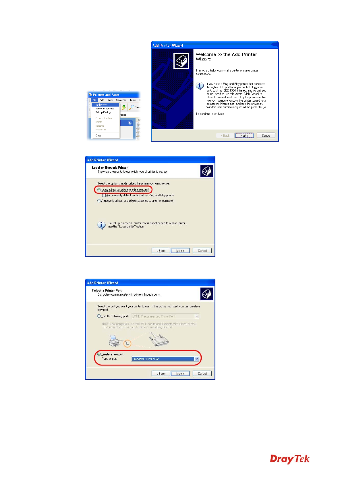
4. Click Local printer attached to this computer and click Next.
5. In this dialog, choose Create a new port Type of port and use the drop down list to
select Standard TCP/IP Port. Click Next.
Vigor2830 Series User’s Guide
10
Page 23
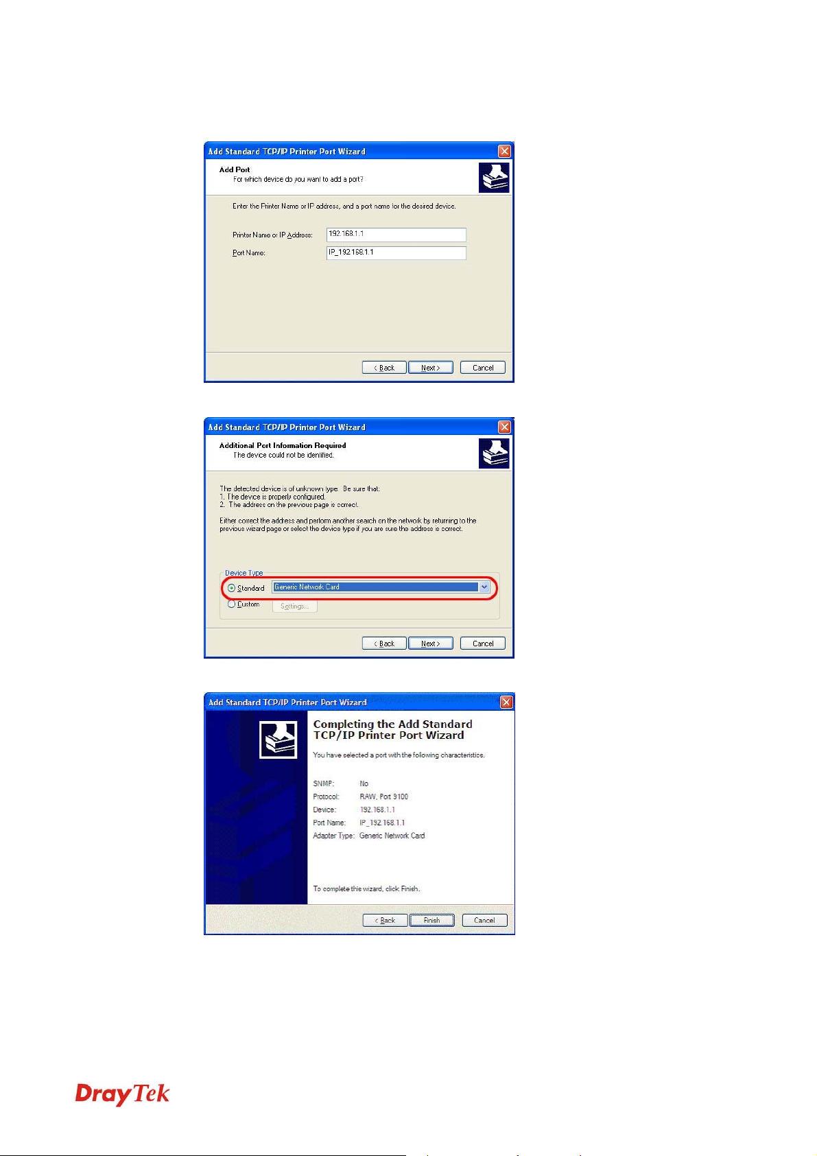
6. In the following dialog, type 192.168.1.1 (router’s LAN IP) in the field of Printer Name
or IP Address and type IP_192.168.1.1 as the port name. Then, click Next.
7. Click Standard and choose Generic Network Card.
8. Then, in the following dialog, click Finish.
11
Vigor2830 Series User’s Guide
Page 24
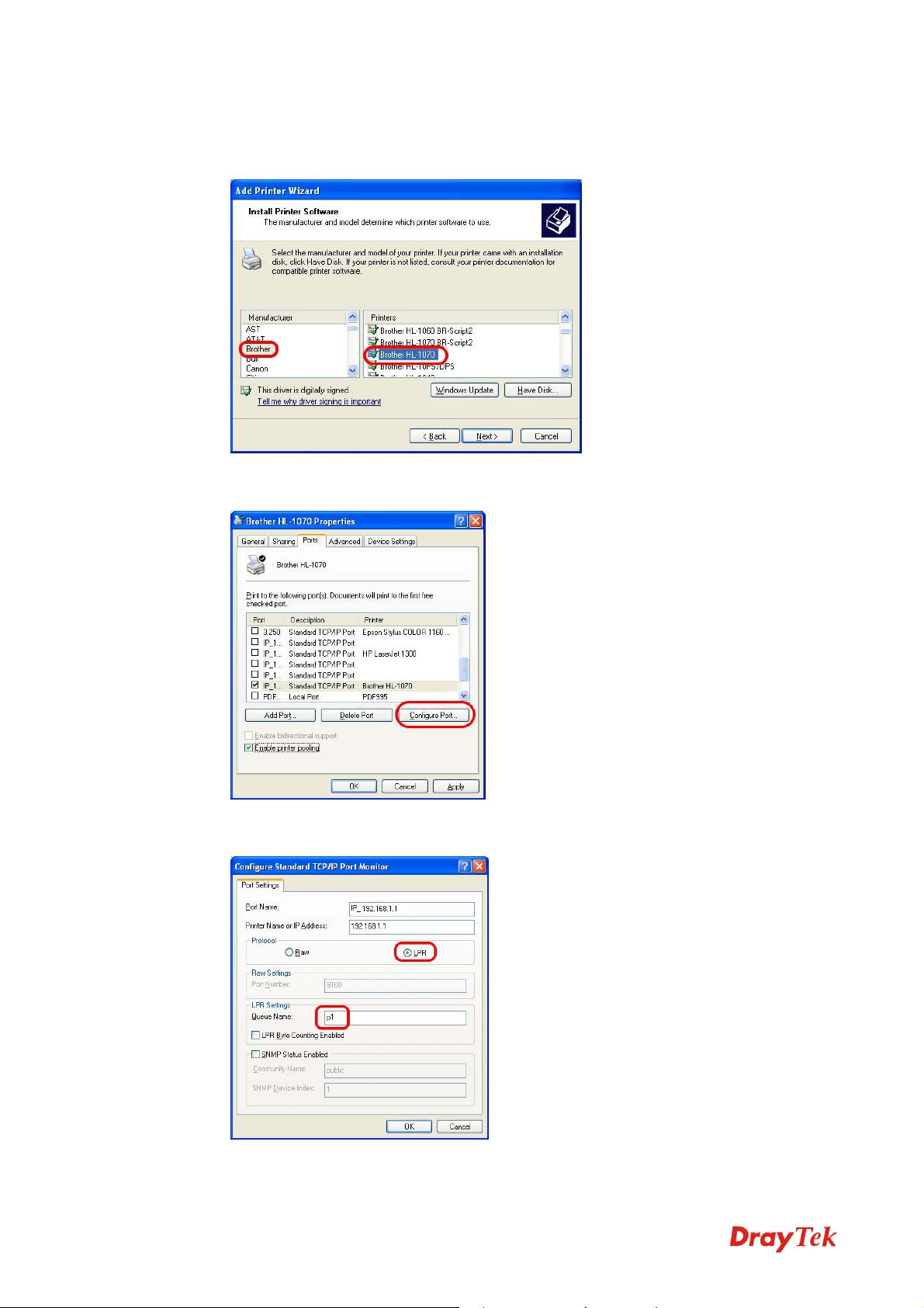
9. Now, your system will ask you to choose right name of the printer that you installed onto
the router. Such step can make correct driver loaded onto your PC. When you finish the
selection, click Next.
10. For the final stage, you need to go back to Control Panel-> Printers and edit the
property of the new printer you have added.
11. Select "LPR" on Protocol, type p1 (number 1) as Queue Name. Then click OK. Next
please refer to the red rectangle for choosing the correct protocol and LPR name.
Vigor2830 Series User’s Guide
12
Page 25

The printer can be used for printing now. Most of the printers with different manufacturers are
compatible with vigor router.
Note 1: Some printers with the fax/scanning or other additional functions are not
supported. If you do not know whether your printer is supported or not, please visit
www.DrayTek.com to find out the printer list. Open Support >FAQ; find out the link of
Printer Server and click it; then click the What types of printers are compatible with
Vigor router? link.
Note 2: Vigor router supports printing request from computers via LAN ports but not
WAN port.
13
Vigor2830 Series User’s Guide
Page 26

This page is left blank.
Vigor2830 Series User’s Guide
14
Page 27
2
Coonnffiigguurriinngg
C
For using the router properly, it is necessary for you to change the password of web
configuration for security and adjust primary basic settings.
22..11 TTwwoo--LLeevveell MMaannaaggeemmeenntt
This chapter explains how to setup a password for an administrator/user and how to adjust
basic/advanced settings for accessing Internet successfully.
For user mode operation, do not type any word on the window and click Login for
the simple web pages for configuration.
Yet, for admin mode operation, please type “admin/admin” on Username/Password
and click Login for full configuration.
22..22 AAcccceessssiinngg WWeebb PPaaggee
1. Make sure your PC connects to the router correctly.
You may either simply set up your computer to get IP dynamically from the router or set
up the IP address of the computer to be the same subnet as the default IP address of
Vigor router 192.168.1.1. For the detailed information, please refer to the later section Trouble Shooting of the guide.
Baassiicc
B
Seettttiinnggss
S
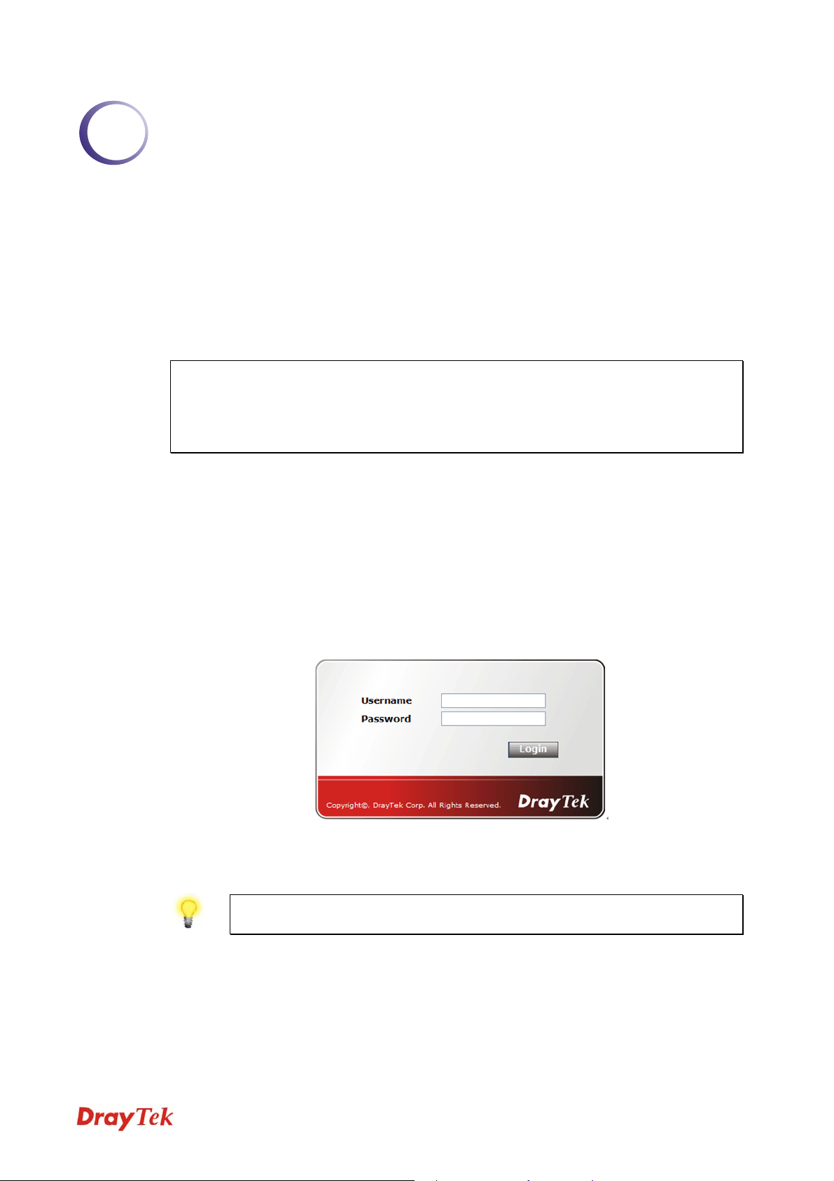
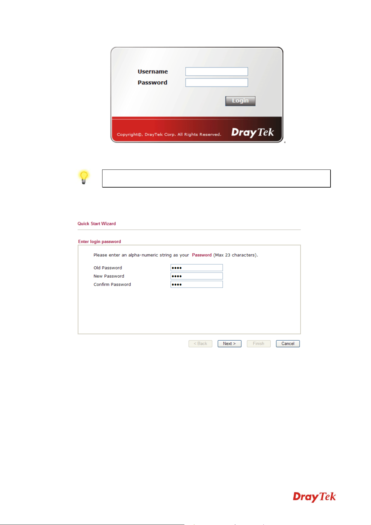
2. Open a web browser on your PC and type http://192.168.1.1. The following window
will be open to ask for username and password.
3. For user mode operation, do not type any word on the window and click Login for the
simple web pages for configuration. Yet, for admin mode operation, please type
“admin/admin” on Username/Password and click Login for full configuration.
Notice: If you fail to access to the web configuration, please go to “Trouble
Shooting” for detecting and solving your problem.
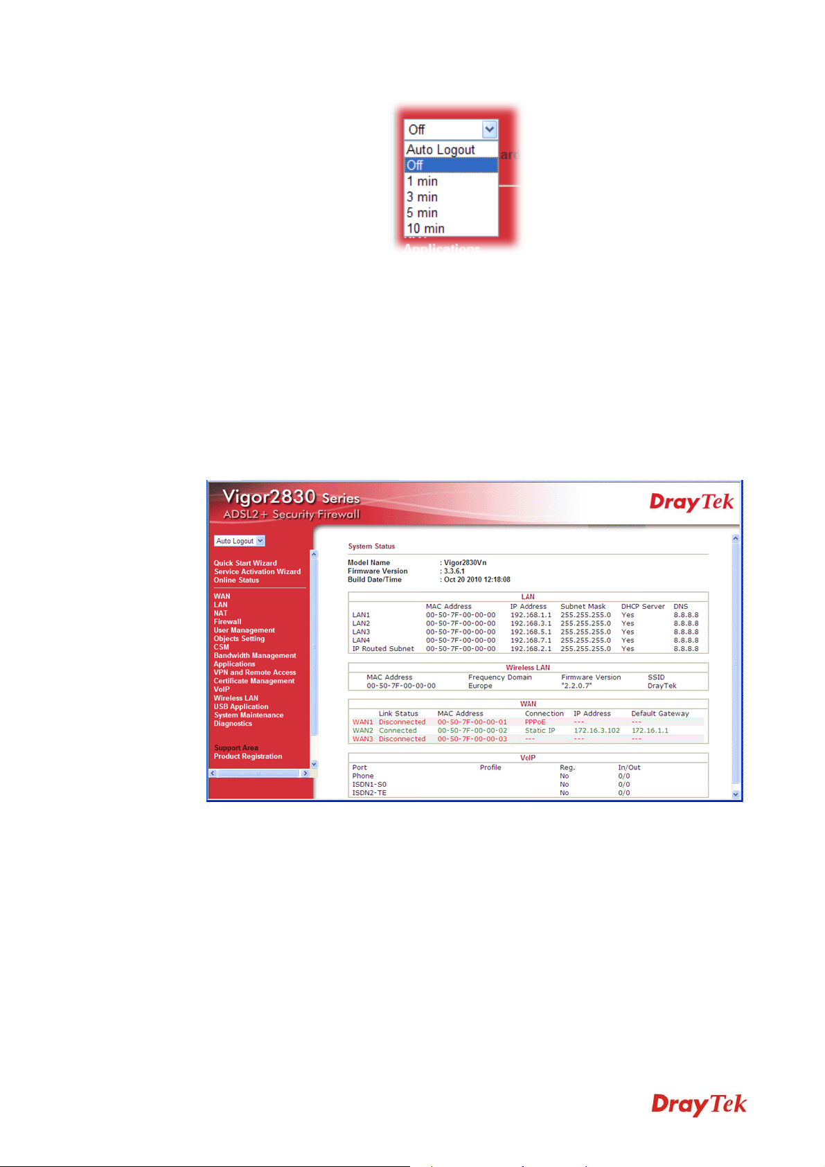
4. The web page can be logged out according to the chosen condition. The default setting is
Auto Logout, which means the web configuration system will logout after 5 minutes
without any operation. Change the setting for your necessity.
15
Vigor2830 Series User’s Guide
Page 28
22..33 CChhaannggiinngg PPaasssswwoorrdd
No matter user mode operation or admin mode operation, please change the password for the
original security of the router.
1. Open a web browser on your PC and type http://192.168.1.1. A pop-up window will
open to ask for username and password.
2. Please type “admin/admin” on Username/Password for admin mode. Otherwise, do not
type any word (both username and password are Null for user mode) on the window and
click Login on the window.
3. Now, the Main Screen will appear.
Main screen for admin mode operation (full configuration)
Vigor2830 Series User’s Guide
16
Page 29
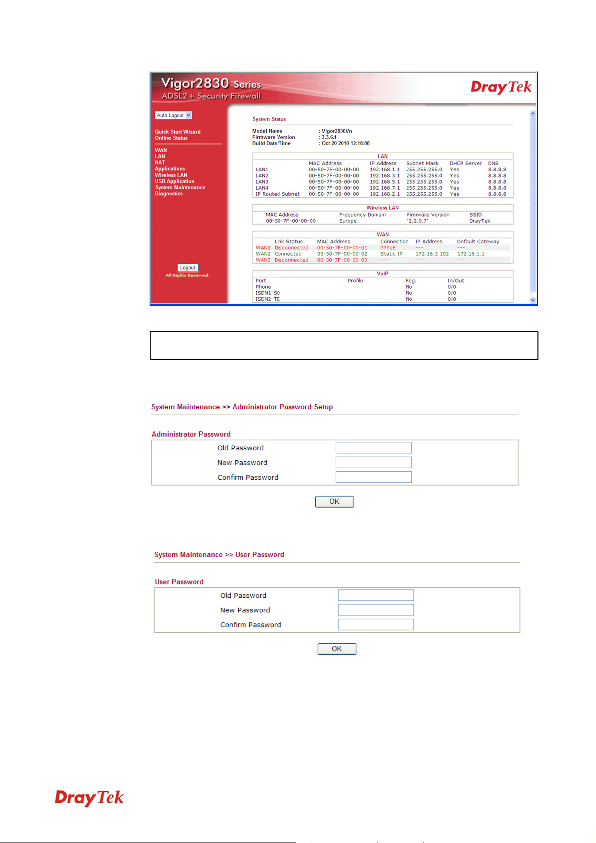
Main screen for user mode operation (simple configuration)
Note: The home page will change slightly in accordance with the type of the router
you have.
4. Go to System Maintenance page and choose Administrator Password/User
Password.
or
5. Enter the login password (the default is blank) on the field of Old Password. Type New
Password. Then click OK to continue.
6. Now, the password has been changed. Next time, use the new password to access the
Web Configurator for this router.
17
Vigor2830 Series User’s Guide
Page 30
22..44 QQuuiicckk SSttaarrtt WWiizzaarrdd
Notice: Quick Start Wizard for user mode operation is the same as for admin
mode operation.
If your router can be under an environment with high speed NAT, the configuration provide
here can help you to deploy and use the router quickly. The first screen of Quick Start
Wizard is entering login password. After typing the password, please click Next.
On the next page as shown below, please select the WAN interface that you use. If DSL
interface is used, please choose WAN1; if Ethernet interface is used, please choose WAN2; if
3G USB modem is used, please choose WAN3. Then click Next for next step.
Vigor2830 Series User’s Guide
18
Page 31
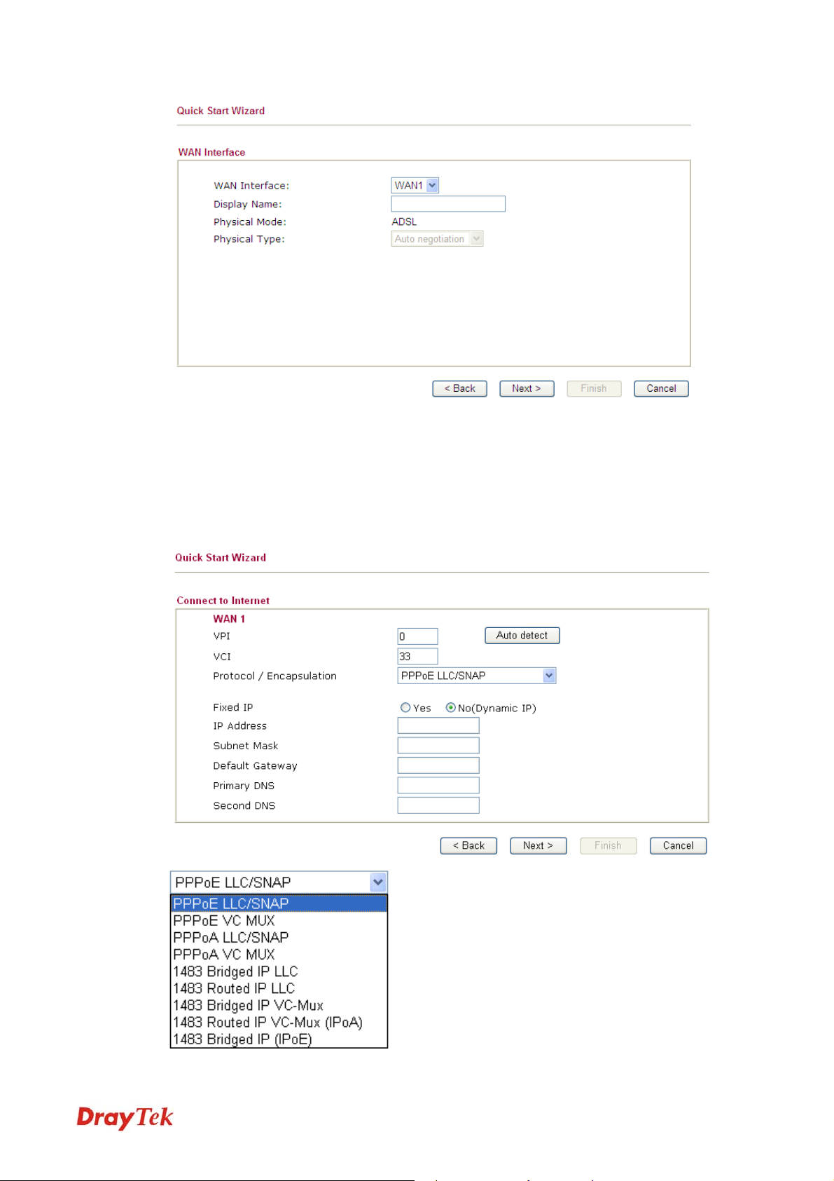
WAN1, WAN2 and WAN3 will bring up different configuration page. Refer to the following
for detailed information.
22..44..11 FFoorr WWAANN11
Choose WAN1 and click Next to display the following page. Please select the appropriate
Internet access type according to the information from your ISP. For example, you should
select PPPoE mode if the ISP provides you PPPoE interface. Then click Next for next step.
19
Vigor2830 Series User’s Guide
Page 32

22..44..11..11 PPPPPPooEE
PPPoE/PPPoA: PPPoE stands for Point-to-Point Protocol over Ethernet. It relies on two
widely accepted standards: PPP and Ethernet. It connects users through an Ethernet to the
Internet with a common broadband medium, such as a single DSL line, wireless device or
cable modem. All the users over the Ethernet can share a common connection.
PPPoE is used for most of DSL modem users. All local users can share one PPPoE connection
for accessing the Internet. Your service provider will provide you information about user name,
password, and authentication mode.
If you click PPPoE or PPPoA as the protocol, please manually enter the Username/Password
provided by your ISP. Then click Next.
User Name
Assign a specific valid user name provided by the
ISP.
Password
Confirm Password
Assign a valid password provided by the ISP.
Retype the password.
Click Next for viewing summary of such connection.
Vigor2830 Series User’s Guide
20
Page 33

Click Finish. A page of Quick Start Wizard Setup OK!!! will appear. Then, the system
status of this protocol will be shown.
Now, you can enjoy surfing on the Internet.
22..44..11..11 11448833 BBrriiddggeedd IIPP //11448833 RRoouutteedd IIPP
If you choose 1483 Bridged IP / 1483 Routed IP as the protocol, you will get the following
page. Please type in the IP address information originally provided by your ISP. Then click
Next for next step.
Now you can see the following screen. It indicates that the setup is complete. Different types
of connection modes will have different summary.
21
Vigor2830 Series User’s Guide
Page 34

Click Finish. A page of Quick Start Wizard Setup OK!!! will appear. Then, the system
status of this protocol will be shown.
Now, you can enjoy surfing on the Internet.
22..44..22 FFoorr WWAANN22
WAN2 is dedicated to physical mode in Ethernet. If you choose WAN2, please specify
physical type. Then, click Next.
On the next page as shown below, please select the appropriate Internet access type according
to the information from your ISP. For example, you should select PPPoE mode if the ISP
provides you PPPoE interface. Then click Next for next step.
Vigor2830 Series User’s Guide
22
Page 35

22..44..22..11 PPPPPPooEE
PPPoE stands for Point-to-Point Protocol over Ethernet. It relies on two widely accepted
standards: PPP and Ethernet. It connects users through an Ethernet to the Internet with a
common broadband medium, such as a single DSL line, wireless device or cable modem. All
the users over the Ethernet can share a common connection.
PPPoE is used for most of DSL modem users. All local users can share one PPPoE connection
for accessing the Internet. Your service provider will provide you information about user name,
password, and authentication mode.
If you click PPPoE as the protocol, please manually enter the Username/Password provided by
your ISP. Then click Next.
User Name Assign a specific valid user name provided by the ISP.
Password Assign a valid password provided by the ISP.
Confirm Password Retype the password.
Click Next for viewing summary of such connection.
23
Vigor2830 Series User’s Guide
Page 36

Click Finish. A page of Quick Start Wizard Setup OK!!! will appear. Then, the system
status of this protocol will be shown.
Now, you can enjoy surfing on the Internet.
22..44..22..22 PPPPTTPP//LL22TTPP
If you click PPTP/L2TP, you will get the following page. Please type in all the information
originally provided by your ISP.
Click Next for viewing summary of such connection.
Click Finish. A page of Quick Start Wizard Setup OK!!! will appear. Then, the system
status of this protocol will be shown.
Vigor2830 Series User’s Guide
24
Page 37

Now, you can enjoy surfing on the Internet.
22..44..22..33 SSttaattiicc IIPP
If you click Static IP, you will get the following page. Please type in the IP address
information originally provided by your ISP. Then click Next for next step.
Click Next for viewing summary of such connection.
Click Finish. A page of Quick Start Wizard Setup OK!!! will appear. Then, the system
status of this protocol will be shown.
25
Vigor2830 Series User’s Guide
Page 38

Now, you can enjoy surfing on the Internet.
22..44..22..44 DDHHCCPP
If you click DHCP, you will get the following page. Simply click Next to continue.
Click Next for viewing summary of such connection.
Click Finish. A page of Quick Start Wizard Setup OK!!! will appear. Then, the system
status of this protocol will be shown.
Now, you can enjoy surfing on the Internet.
Vigor2830 Series User’s Guide
26
Page 39
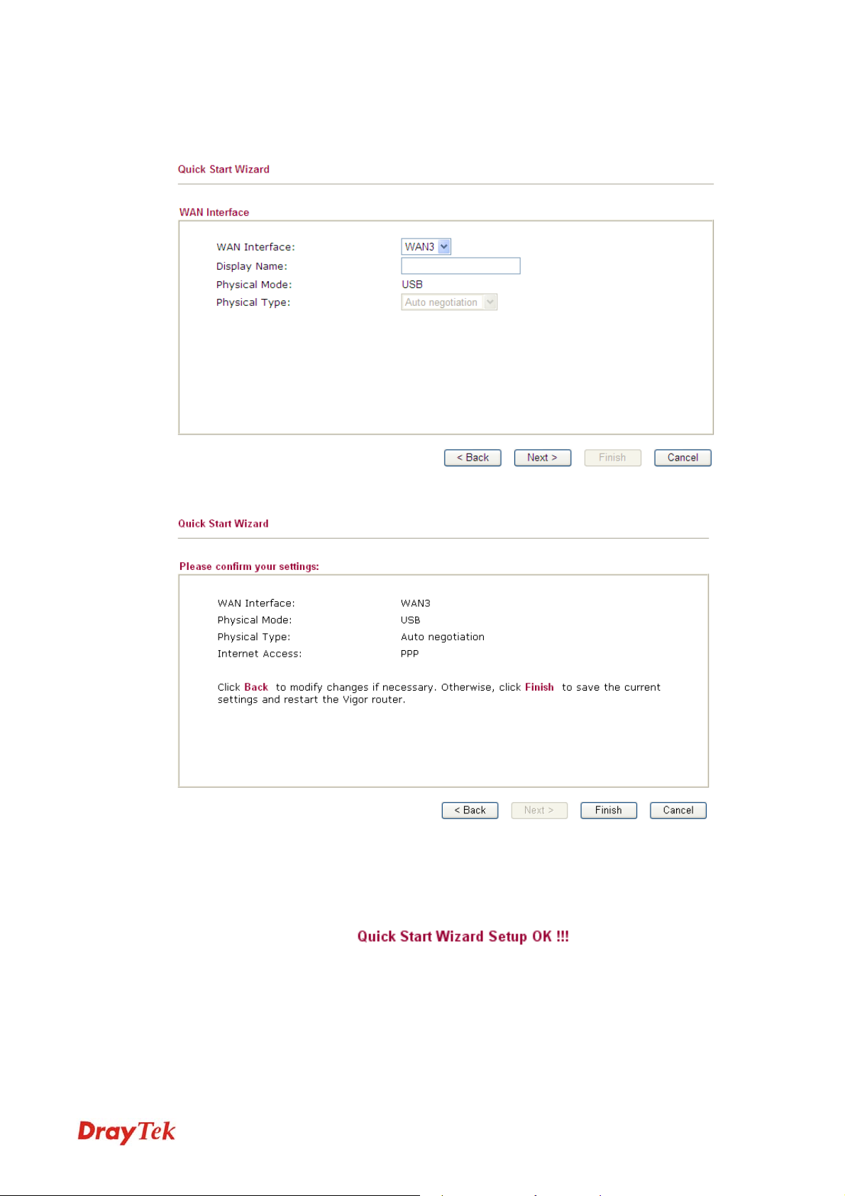
22..44..33 FFoorr WWAANN33
To use 3G USB modem for network connection, please choose WAN3.
Then, click Next to continue.
Click Finish. A page of Quick Start Wizard Setup OK!!! will appear. Then, the system
status of this protocol will be shown.
Now, you can enjoy surfing on the Internet.
27
Vigor2830 Series User’s Guide
Page 40

22..55 SSeerrvviiccee AAccttiivvaattiioonn WWiizzaarrdd
Service Activation Wizard can guide you to activate WCF service (Web Content Filter) with a
quick and easy way. For the Service Activation Wizard is only available for admin
operation, therefore, please type “admin/admin” on Username/Password while Logging
into the web configurator.
Service Activation Wizard is a tool which allows you to use trial version or update the license
of WCF directly without accessing into the server (MyVigor) located on
http://myvigor.draytek.com
Web Content Filter Profile for detailed information.
Now, follow the steps listed below to activate WCF feature for your router.
1. Open Service Activation Wizard.
2. The screen of Service Activation Wizard will be shown as follows. Choose the one you
need and click Next. In this case, we choose to activate free trail edition.
. For using Web Content Filter Profile, please refer to later section
Free trial edition: it offers a period of trial for you to get acquainted with WCF function.
Formal edition with license key: you can extend the license valid time manually.
Note: If you activate Formal edition with license key first, the free trial edition will
be invalid.
3. In the following page, you can activate the Web content filter services at the same time
or individually. When you finish the selection, please click Next.
Vigor2830 Series User’s Guide
28
Page 41
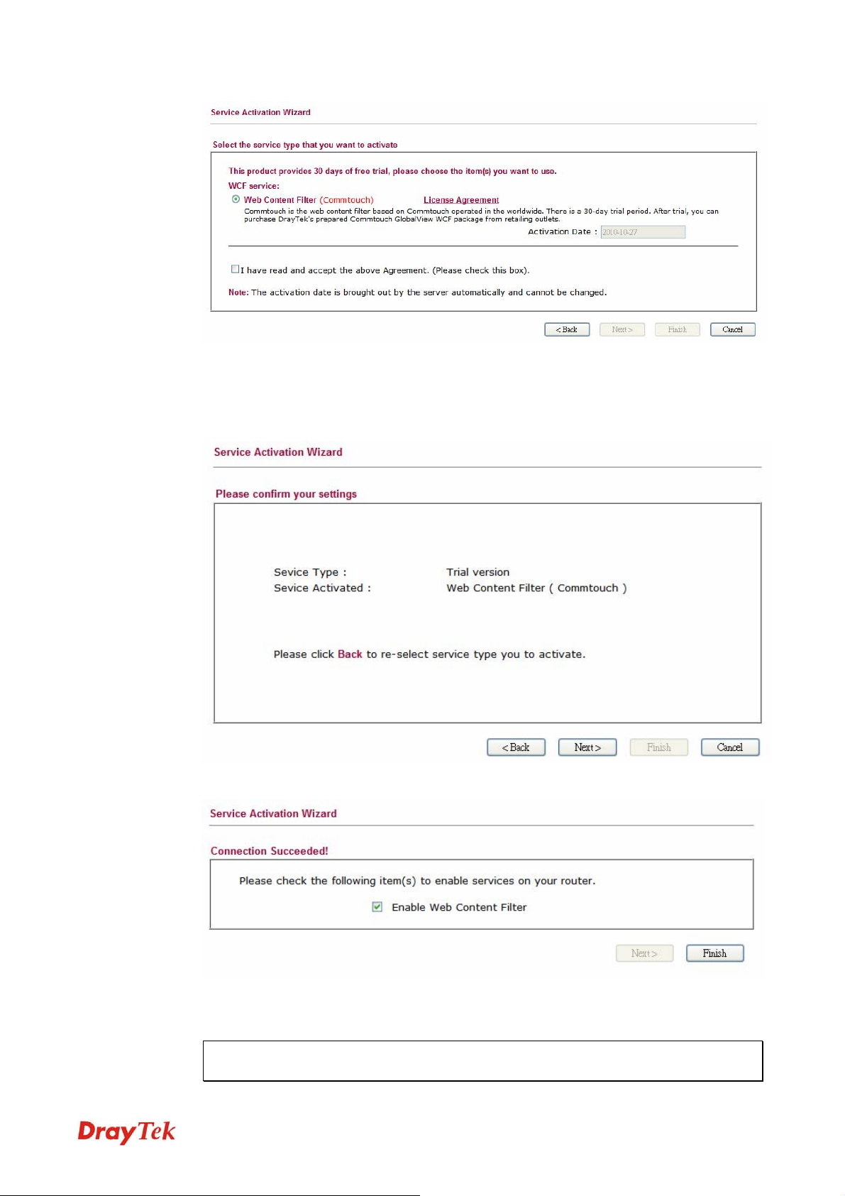
Commtouch is the web content filter based on Commtouch operated in the worldwide.
There is a 30-day trial period. After trial, you can purchase DrayTek's prepared
Commtouch GlobalView WCF package from retailing outlets.
4. Setting confirmation page will be displayed as follows, please click Next.
5. Wait for a moment till the following page appears.
When such page appears, you can enable or disable these services for your necessity.
Then, click Finish.
Note: The service will be activated and applied as the default rule configured in
Firewall>>General Setup.
29
Vigor2830 Series User’s Guide
Page 42

6. Now, the web page will display the service that you have activated according to your
selection(s). The valid time for the free trial of these services is one month.
Later, if you need to extend the license valid time for the same service, you can also
use the Service Activation Wizard again to reach your goal by clicking the radio
button of Formal edition with license key and clicking Next.
Vigor2830 Series User’s Guide
30
Page 43
22..66 OOnnlliinnee SSttaattuuss
22..66..11 PPhhyyssiiccaall CCoonnnneeccttiioonn
Such page displays the physical connection status such as LAN connection status, WAN
connection status, ADSL information, and so on.
If you select PPPoE as the protocol, you will find out a link of Dial PPPoE or Drop PPPoE
in the Online Status web page.
Detailed explanation is shown below:
Primary DNS Displays the IP address of the primary DNS.
Secondary DNS Displays the IP address of the secondary DNS.
LAN Status
IP Address Displays the IP address of the LAN interface.
TX Packets Displays the total transmitted packets at the LAN interface.
RX Packets Displays the total number of received packets at the LAN interface.
WAN Status
Line Displays the physical connection (Ethernet) of this interface.
Name Displays the name set in WAN1/WAN web page.
Mode Displays the type of WAN connection (e.g., PPPoE).
31
Vigor2830 Series User’s Guide
Page 44

Up Time Displays the total uptime of the interface.
IP Displays the IP address of the WAN interface.
GW IP Displays the IP address of the default gateway.
TX Packets Displays the total transmitted packets at the WAN interface.
TX Rate Displays the speed of transmitted octets at the WAN interface.
RX Packets Displays the total number of received packets at the WAN interface.
RX Rate Displays the speed of received octets at the WAN interface.
Note: The words in green mean that the WAN connection of that interface is ready for
accessing Internet; the words in red mean that the WAN connection of that interface is not
ready for accessing Internet.
22..66..22 VViirrttuuaall WWAANN
Such page displays the virtual WAN connection information.
Virtual WAN are used by TR-069 management, VoIP service and so on.
The field of Application will list the purpose of such WAN connection.
22..77 SSaavviinngg CCoonnffiigguurraattiioonn
Each time you click OK on the web page for saving the configuration, you can find messages
showing the system interaction with you.
Ready indicates the system is ready for you to input settings.
Settings Saved means your settings are saved once you click Finish or OK button.
Vigor2830 Series User’s Guide
32
Page 45

3
Usseerr
U
This chapter will guide users to execute simple configuration through user mode operation. As
for other examples of application, please refer to chapter 5.
1. Open a web browser on your PC and type http://192.168.1.1. The window will ask for
typing username and password.
2. Do not type any word (both username and password are Null for user operation) on the
window and click Login on the window.
Now, the Main Screen will appear. Be aware that “User mode” will be displayed on the
bottom left side.
Mooddee
M
Oppeerraattiioonn
O
33..11 WWAANN
33..11..11 BBaassiiccss ooff IInntteerrnneett PPrroottooccooll ((IIPP)) NNeettwwoorrkk
Quick Start Wizard offers user an easy method to quick setup the connection mode for the router. Moreover, if you want to adjust more settings for different WAN modes, please go to WAN group.
IP means Internet Protocol. Every device in an IP-based Network including routers, print
server, and host PCs, needs an IP address to identify its location on the network. To avoid
address conflicts, IP addresses are publicly registered with the Network Information Centre
(NIC). Having a unique IP address is mandatory for those devices participated in the public
network but not in the private TCP/IP local area networks (LANs), such as host PCs under the
management of a router since they do not need to be accessed by the public. Hence, the NIC
has reserved certain addresses that will never be registered publicly. These are known as
private IP addresses, and are listed in the following ranges:
33
Vigor2830 Series User’s Guide
Page 46

From 10.0.0.0 to 10.255.255.255
From 172.16.0.0 to 172.31.255.255
From 192.168.0.0 to 192.168.255.255
WWhhaatt aarree PPuubblliicc IIPP AAddddrreessss aanndd PPrriivvaattee IIPP AAddddrreessss
As the router plays a role to manage and further protect its LAN, it interconnects groups of
host PCs. Each of them has a private IP address assigned by the built-in DHCP server of the
Vigor router. The router itself will also use the default private IP address: 192.168.1.1 to
communicate with the local hosts. Meanwhile, Vigor router will communicate with other
network devices through a public IP address. When the data flow passing through, the
Network Address Translation (NAT) function of the router will dedicate to translate
public/private addresses, and the packets will be delivered to the correct host PC in the local
area network. Thus, all the host PCs can share a common Internet connection.
GGeett YYoouurr PPuubblliicc IIPP AAddddrreessss ffrroomm IISSPP
In ADSL deployment, the PPP (Point to Point)-style authentication and authorization is
required for bridging customer premises equipment (CPE). Point to Point Protocol over
Ethernet (PPPoE) connects a network of hosts via an access device to a remote access
concentrator or aggregation concentrator. This implementation provides users with significant
ease of use. Meanwhile it provides access control, billing, and type of service according to
user requirement.
When a router begins to connect to your ISP, a serial of discovery process will occur to ask for
a connection. Then a session will be created. Your user ID and password is authenticated via
PAP or CHAP with RADIUS authentication system. And your IP address, DNS server, and
other related information will usually be assigned by your ISP.
NNeettwwoorrkk CCoonnnneeccttiioonn bbyy 33GG UUSSBB MMooddeemm
For 3G mobile communication through Access Point is popular more and more, Vigor2830
adds the function of 3G network connection for such purpose. By connecting 3G USB Modem
to the USB port of Vigor2830, it can support HSDPA/UMTS/EDGE/GPRS/GSM and the
future 3G standard (HSUPA, etc). Vigor2830n with 3G USB Modem allows you to receive 3G
signals at any place such as your car or certain location holding outdoor activity and share the
bandwidth for using by more people. Users can use four LAN ports on the router to access
Internet. Also, they can access Internet via 802.11n wireless function of Vigor2830n, and
enjoy the powerful firewall, bandwidth management, VPN features of Vigor2830n series.
After connecting into the router, 3G USB Modem will be regarded as the third WAN port.
However, the original WAN1 and WAN2 still can be used and Load-Balance can be done in
the router. Besides, 3G USB Modem in WAN3 also can be used as backup device. Therefore,
when WAN1 and WAN2 are not available, the router will use 3.5G for supporting
Vigor2830 Series User’s Guide
34
Page 47

automatically. The supported 3G USB Modem will be listed on Draytek web site. Please visit
www.draytek.com for more detailed information.
Below shows the menu items for WAN.
33..11..22 GGeenneerraall SSeettuupp
This section will introduce some general settings of Internet and explain the connection modes
for WAN1, WAN2 and WAN3 in details.
This router supports multiple-WAN function. It allows users to access Internet and combine
the bandwidth of the multiple WANs to speed up the transmission through the network. Each
WAN port can connect to different ISPs, Even if the ISPs use different technology to provide
telecommunication service (such as DSL, Cable modem, etc.). If any connection problem
occurred on one of the ISP connections, all the traffic will be guided and switched to the
normal communication port for proper operation. Please configure WAN1, WAN2 and WAN3
settings.
This webpage allows you to set general setup for WAN1, WAN2 and WAN3 respectively.
Load Balance Mode
Index
Enable
Physical Mode / Type
Line Speed
Active Mode
This option is available for multiple-WAN for getting enough
bandwidth for each WAN port. If you know the practical
bandwidth for your WAN interface, please choose the setting of
According to Line Speed. Otherwise, please choose Auto
Weight to let the router reach the best load balance.
Click the WAN interface link under Index to access into the
WAN configuration page.
V means such WAN interface is enabled and ready to be used.
Display the physical mode and physical type of such WAN
interface.
Display the downstream and upstream rate of such WAN
interface.
Display whether such WAN interface is Active device or backup
35
Vigor2830 Series User’s Guide
Page 48

device.
Backup WAN
Display the Backup WAN interface for such WAN when it is
disabled.
Note: In default, each WAN port is enabled.
WWAANN11 wwiitthh AADDSSLL
WAN1 is fixed with physical mode of ADSL.
Enable
Display Name
Physical Mode
Physical type
Line Speed
VLAN Tag insertion
Choose Yes to invoke the settings for this WAN interface.
Choose No to disable the settings for this WAN interface.
Type the description for such WAN interface.
Display the physical mode of such WAN interface.
In such WAN interface, no type can be selected.
If your choose According to Line Speed as the Load Balance
Mode, please type the line speed for downloading and
uploading for such WAN interface. The unit is kbps.
Enable – Enable the function of VLAN with tag.
The router will add specific VLAN number to all packets on the
WAN while sending them out.
Please type the tag value and specify the priority for the packets
sending by WAN1.
Disable – Disable the function of VLAN with tag.
Tag value – Type the value as the VLAN ID number. The
range is form 0 to 4095.
Priority – Type the packet priority number for such VLAN.
The range is from 0 to 7.
Active Mode and Backup
WAN/Backup Type
Vigor2830 Series User’s Guide
Active Mode – Determine the WAN interface will be active for
always (Always On) or be treated as a backup WAN interface
(Backup WAN).
36
Page 49

Backup WAN/Backup Type – Determine the role of such
WAN interface. It will be changed according to the Active
Mode specified.
If you choose Always On as Active Mode, you can choose one
of the backup WAN interfaces from the Backup WAN drop
down list. Later, when such WAN is disconnected for some
reason, the backup WAN will be activated automatically to
prevent data transmission from connection interrupted.
If you choose Backup as the Active Mode, Backup WAN will
be changed into Backup Type. You have to specify which role
the WAN interface should play if you want to backup multiple
WANs. However, ignore this setting if you want to backup a
single WAN.
When any WAN disconnect – Such backup WAN will be
activated when any master WAN interface disconnects.
When all WAN disconnect – Such backup WAN will be
activated only when all master WAN interfaces disconnect.
37
Vigor2830 Series User’s Guide
Page 50

WWAANN22 wwiitthh EEtthheerrnneett
WAN2 is fixed with physical mode of Giga Ethernet.
Enable
Choose Yes to invoke the settings for this WAN interface.
Choose No to disable the settings for this WAN interface.
Display Name
Physical Mode
Physical type
Line Speed
VLAN Tag insertion
Type the description for such WAN interface.
Display the physical mode of such WAN interface.
You can change the physical type for WAN2 or choose Auto
negotiation for determined by the system.
If your choose According to Line Speed as the Load Balance
Mode, please type the line speed for downloading and
uploading for such WAN interface. The unit is kbps.
Enable – Enable the function of VLAN with tag.
The router will add specific VLAN number to all packets on the
WAN while sending them out.
Please type the tag value and specify the priority for the packets
sending by WAN1.
Disable – Disable the function of VLAN with tag.
Active Mode and Backup
Vigor2830 Series User’s Guide
Tag value – Type the value as the VLAN ID number. The
range is form 0 to 4095.
Priority – Type the packet priority number for such VLAN.
The range is from 0 to 7.
Active Mode – Determine the WAN interface will be active for
38
Page 51

WAN/Backup Type
always (Always On) or be treated as a backup WAN interface
(Backup WAN).
Backup WAN/Backup Type – Determine the role of such
WAN interface. It will be changed according to the Active
Mode specified.
If you choose Always On as Active Mode, you can choose one
of the backup WAN interfaces from the Backup WAN drop
down list. Later, when such WAN is disconnected for some
reason, the backup WAN will be activated automatically to
prevent data transmission from connection interrupted.
If you choose Backup as the Active Mode, Backup WAN will
be changed into Backup Type. You have to specify which role
the WAN interface should play if you want to backup multiple
WANs. However, ignore this setting if you want to backup a
single WAN.
When any WAN disconnect – Such backup WAN will be
activated when any master WAN interface disconnects.
When all WAN disconnect – Such backup WAN will be
activated only when all master WAN interfaces disconnect.
WWAANN33 wwiitthh UUSSBB
To use 3G network connection through 3G USB Modem, please configure WAN3 interface.
39
Vigor2830 Series User’s Guide
Page 52

Enable
Choose Yes to invoke the settings for this WAN interface.
Choose No to disable the settings for this WAN interface.
Display Name
Physical Mode
Physical type
Line Speed
Active Mode and Backup
WAN/Backup Type
Type the description for such WAN interface.
Display the physical mode of such WAN interface.
In such WAN interface, no type can be selected.
If your choose According to Line Speed as the Load Balance
Mode, please type the line speed for downloading and
uploading for such WAN interface. The unit is kbps.
Active Mode – Determine the WAN interface will be active for
always(Always On) or be treated as a backup WAN
interface(Backup WAN).
Backup WAN/Backup Type – Determine the role of such
WAN interface. It will be changed according to the Active
Mode specified.
If you choose Always On as Active Mode, you can choose one
of the backup WAN interfaces from the Backup WAN drop
down list. Later, when such WAN is disconnected for some
reason, the backup WAN will be activated automatically to
prevent data transmission from connection interrupted.
Vigor2830 Series User’s Guide
If you choose Backup as the Active Mode, Backup WAN will
be changed into Backup Type. You have to specify which role
the WAN interface should play if you want to backup multiple
WANs. However, ignore this setting if you want to backup a
single WAN.
40
Page 53
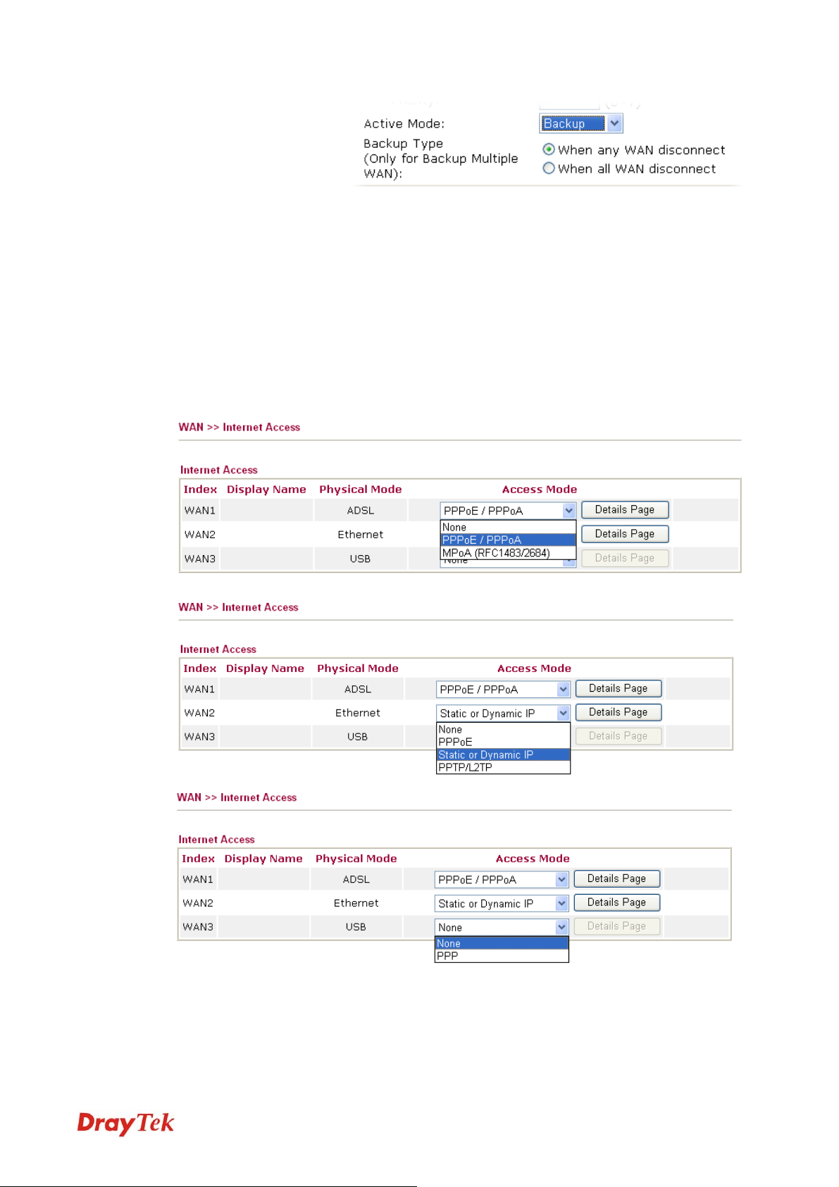
33..11..33 IInntteerrnneett AAcccceessss
For the router supports multi-WAN function, the users can set different WAN settings (for
WAN1/WAN2/WAN3) for Internet Access. Due to different Physical Mode for WAN
interface, the Access Mode for these connections also varies. Refer to the following figures.
When any WAN disconnect – Such backup WAN will be
activated when any master WAN interface disconnects.
When all WAN disconnect – Such backup WAN will be
activated only when all master WAN interfaces disconnect.
Index
Display Name
Physical Mode
Display the WAN interface.
It shows the name of the WAN1/WAN2/WAN3 that entered in
general setup.
It shows the physical connection for WAN1(ADSL)/WAN2
41
Vigor2830 Series User’s Guide
Page 54

(Ethernet) /WAN3 (3G USB Modem) according to the real
network connection.
Access Mode
Use the drop down list to choose a proper access mode. The
details page of that mode will be popped up. If not, click
Details Page for accessing the page to configure the settings.
Details Page
This button will open different web page according to the
access mode that you choose in WAN interface
DDeettaaiillss PPaaggee ffoorr PPPPPPooEE//PPPPPPooAA iinn WWAANN11
PPPoA, included in RFC1483, can be operated in either Logical Link Control-Subnetwork
Access Protocol or VC-Mux mode. As a CPE device, Vigor router encapsulates the PPP
session based for transport across the ADSL loop and your ISP’s Digital Subscriber Line
Access Multiplexer (DSLAM).
To choose PPPoE or PPPoA as the accessing protocol of the internet, please select
PPPoE/PPPoA from the Internet Access menu. The following web page will be shown.
Enable/Disable
DSL Modem Settings
Vigor2830 Series User’s Guide
Click Enable for activating this function. If you click Disable,
this function will be closed and all the settings that you adjusted
in this page will be invalid.
Set up the DSL parameters required by your ISP. These are
vital for building DSL connection to your ISP.
Multi-PVC channel - The selections displayed here are
determined by the page of Internet Access – Multi PVCs.
Select M-PVCs Channel means no selection will be chosen.
VPI - Type in the value provided by ISP.
42
Page 55

VCI - Type in the value provided by ISP.
Encapsulating Type - Drop down the list to choose the type
provided by ISP.
Protocol - Drop down the list to choose the one provided by
ISP.If you have already used Quick Start Wizard to set the
protocol, then it is not necessary for you to change any settings
in this group.
Modulation – Drop down the list to choose a proper
modulation for the router.
PPPoE Pass-through
WAN Connection
Detection
ISP Access Setup
The router offers PPPoE dial-up connection. Besides, you also
can establish the PPPoE connection directly from local clients
to your ISP via the Vigor router. When PPPoA protocol is
selected, the PPPoE package transmitted by PC will be
transformed into PPPoA package and sent to WAN server.
Thus, the PC can access Internet through such direction.
For Wired LAN – If you check this box, PCs on the same
network can use another set of PPPoE session (different with
the Host PC) to access into Internet.
For Wireless LAN – If you check this box, PCs on the same
wireless network can use another set of PPPoE session
(different with the Host PC) to access into Internet.
Such function allows you to verify whether network connection
is alive or not through ARP Detect or Ping Detect.
Mode – Choose ARP Detect or Ping Detect for the system to
execute for WAN detection.
Ping IP – If you choose Ping Detect as detection mode, you
have to type IP address in this field for pinging.
TTL (Time to Live) – Displays value for your reference. TTL
value is set by telnet command.
Enter your allocated username, password and authentication
parameters according to the information provided by your ISP.
If you want to connect to Internet all the time, you can check
Always On.
IP Address From ISP
Username – Type in the username provided by ISP in this
field.
Password – Type in the password provided by ISP in this field.
PPP Authentication – Select PAP only or PAP or CHAP for
PPP.
Idle Timeout – Set the timeout for breaking down the Internet
after passing through the time without any action. This setting
is active only when the Active on demand option for Active
Mode is selected in WAN>> General Setup page.
Usually ISP dynamically assigns IP address to you each time
you connect to it and request. In some case, your ISP provides
service to always assign you the same IP address whenever you
request. In this case, you can fill in this IP address in the Fixed
IP field. Please contact your ISP before you want to use this
function.
43
Vigor2830 Series User’s Guide
Page 56

WAN IP Alias - If you have multiple public IP addresses and
would like to utilize them on the WAN interface, please use
WAN IP Alias. You can set up to 8 public IP addresses other
than the current one you are using. Notice that this setting is
available for WAN1 only. Type the additional WAN IP address
and check the Enable box. Then click OK to exit the dialog.
Fixed IP – Click Yes to use this function and type in a fixed IP
address in the box of Fixed IP Address.
Default MAC Address – You can use Default MAC
Address or specify another MAC address by typing on the
boxes of MAC Address for the router.
Specify a MAC Address – Type the MAC address for the
router manually.
After finishing all the settings here, please click OK to activate them.
Vigor2830 Series User’s Guide
44
Page 57

DDeettaaiillss PPaaggee ffoorr MMPPooAA iinn WWAANN11
MPoA is a specification that enables ATM services to be integrated with existing LANs,
which use either Ethernet, or TCP/IP protocols. The goal of MPoA is to allow different LANs
to send packets to each other via an ATM backbone.
To use MPoA as the accessing protocol of the Internet, select MPoA mode. The following
web page will appear.
Enable/Disable
DSL Modem Settings
WAN Connection
Detection
Click Enable for activating this function. If you click Disable,
this function will be closed and all the settings that you adjusted
in this page will be invalid.
Set up the DSL parameters required by your ISP. These are
vital for building DSL connection to your ISP.
Multi-PVC channel - The selections displayed here are
determined by the page of Internet Access – Multi PVCs.
Select M-PVCs Channel means no selection will be chosen.
Encapsulating Type - Drop down the list to choose the type
provided by ISP.
VPI - Type in the value provided by ISP.
VCI - Type in the value provided by ISP.
Modulation – Drop down the list to choose a proper
modulation for the router.
Such function allows you to verify whether network connection
is alive or not through ARP Detect or Ping Detect.
Mode – Choose ARP Detect or Ping Detect for the system to
execute for WAN detection.
45
Vigor2830 Series User’s Guide
Page 58
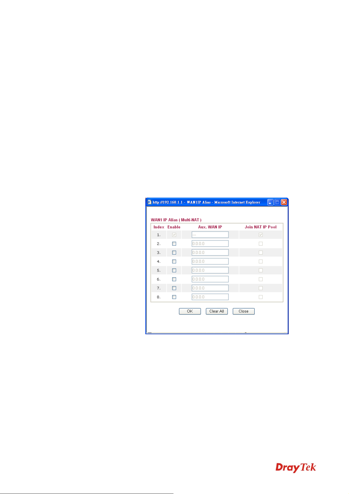
Ping IP – If you choose Ping Detect as detection mode, you
have to type IP address in this field for pinging.
TTL (Time to Live) – Displays value for your reference. TTL
value is set by telnet command.
RIP Protocol
Bridge Mode
WAN IP Network
Settings
Routing Information Protocol is abbreviated as RIP(RFC1058)
specifying how routers exchange routing tables information.
Click Enable RIP for activating this function.
If you choose Bridged IP as the protocol, you can check this
box to invoke the function. The router will work as a bridge
modem.
This group allows you to obtain an IP address automatically
and allows you type in IP address manually.
WAN IP Alias - If you have multiple public IP addresses and
would like to utilize them on the WAN interface, please use
WAN IP Alias. You can set up to 8 public IP addresses other
than the current one you are using. Notice that this setting is
available for WAN1 only. Type the additional WAN IP address
and check the Enable box. Then click OK to exit the dialog.
Vigor2830 Series User’s Guide
Obtain an IP address automatically – Click this button to
obtain the IP address automatically.
Router Name – Type in the router name provided by ISP.
Domain Name – Type in the domain name that you have
assigned.
Specify an IP address – Click this radio button to specify some
data.
IP Address – Type in the private IP address.
Subnet Mask – Type in the subnet mask.
Gateway IP Address – Type in gateway IP address.
Default MAC Address – Type in MAC address for the router.
You can use Default MAC Address or specify another MAC
46
Page 59

address for your necessity.
MAC Address – Type in the MAC address for the router
manually.
DNS Server IP Address
Type in the primary IP address for the router. If necessary, type
in secondary IP address for necessity in the future.
After finishing all the settings here, please click OK to activate them.
DDeettaaiillss PPaaggee ffoorr PPPPPPooEE iinn WWAANN22
To choose PPPoE as the accessing protocol of the Internet, please select PPPoE from the
WAN>>Internet Access >>WAN2 page. The following web page will be shown.
Enable/Disable
ISP Access Setup
WAN Connection
Detection
PPP/MP Setup
Click Enable for activating this function. If you click Disable,
this function will be closed and all the settings that you adjusted
in this page will be invalid.
Enter your allocated username, password and authentication
parameters according to the information provided by your ISP.
Username – Type in the username provided by ISP in this
field.
Password – Type in the password provided by ISP in this field.
Such function allows you to verify whether network connection
is alive or not through ARP Detect or Ping Detect.
Mode – Choose ARP Detect or Ping Detect for the system to
execute for WAN detection.
Ping IP – If you choose Ping Detect as detection mode, you
have to type IP address in this field for pinging.
TTL (Time to Live) – Displays value for your reference. TTL
value is set by telnet command.
PPP Authentication – Select PAP only or PAP or CHAP for
PPP. If you want to connect to Internet all the time, you can
47
Vigor2830 Series User’s Guide
Page 60

check Always On.
Idle Timeout – Set the timeout for breaking down the Internet
after passing through the time without any action.
IP Address Assignment
Method (IPCP)
Usually ISP dynamically assigns IP address to you each time
you connect to it and request. In some case, your ISP provides
service to always assign you the same IP address whenever you
request. In this case, you can fill in this IP address in the Fixed
IP field. Please contact your ISP before you want to use this
function.
WAN IP Alias - If you have multiple public IP addresses and
would like to utilize them on the WAN interface, please use
WAN IP Alias. You can set up to 8 public IP addresses other
than the current one you are using.
After finishing all the settings here, please click OK to activate them.
Vigor2830 Series User’s Guide
Fixed IP – Click Yes to use this function and type in a fixed IP
address in the box of Fixed IP Address.
Default MAC Address – You can use Default MAC Address
or specify another MAC address by typing on the boxes of
MAC Address for the router.
Specify a MAC Address – Type the MAC address for the
router manually.
48
Page 61

DDeettaaiillss PPaaggee ffoorr SSttaattiicc oorr DDyynnaammiicc IIPP iinn WWAANN22
For static IP mode, you usually receive a fixed public IP address or a public subnet, namely
multiple public IP addresses from your DSL or Cable ISP service providers. In most cases, a
Cable service provider will offer a fixed public IP, while a DSL service provider will offer a
public subnet. If you have a public subnet, you could assign an IP address or many IP address
to the WAN interface.
To use Static or Dynamic IP as the accessing protocol of the internet, please click the Static
or Dynamic IP tab. The following web page will be shown.
Enable / Disable
Keep WAN Connection
WAN Connection
Detection
Click Enable for activating this function. If you click Disable,
this function will be closed and all the settings that you adjusted
in this page will be invalid.
Normally, this function is designed for Dynamic IP environments
because some ISPs will drop connections if there is no traffic
within certain periods of time. Check Enable PING to keep alive
box to activate this function.
PING to the IP - If you enable the PING function, please specify
the IP address for the system to PING it for keeping alive.
PING Interval - Enter the interval for the system to execute the
PING operation.
Such function allows you to verify whether network connection is
alive or not through ARP Detect or Ping Detect.
Mode – Choose ARP Detect or Ping Detect for the system to
execute for WAN detection.
49
Vigor2830 Series User’s Guide
Page 62
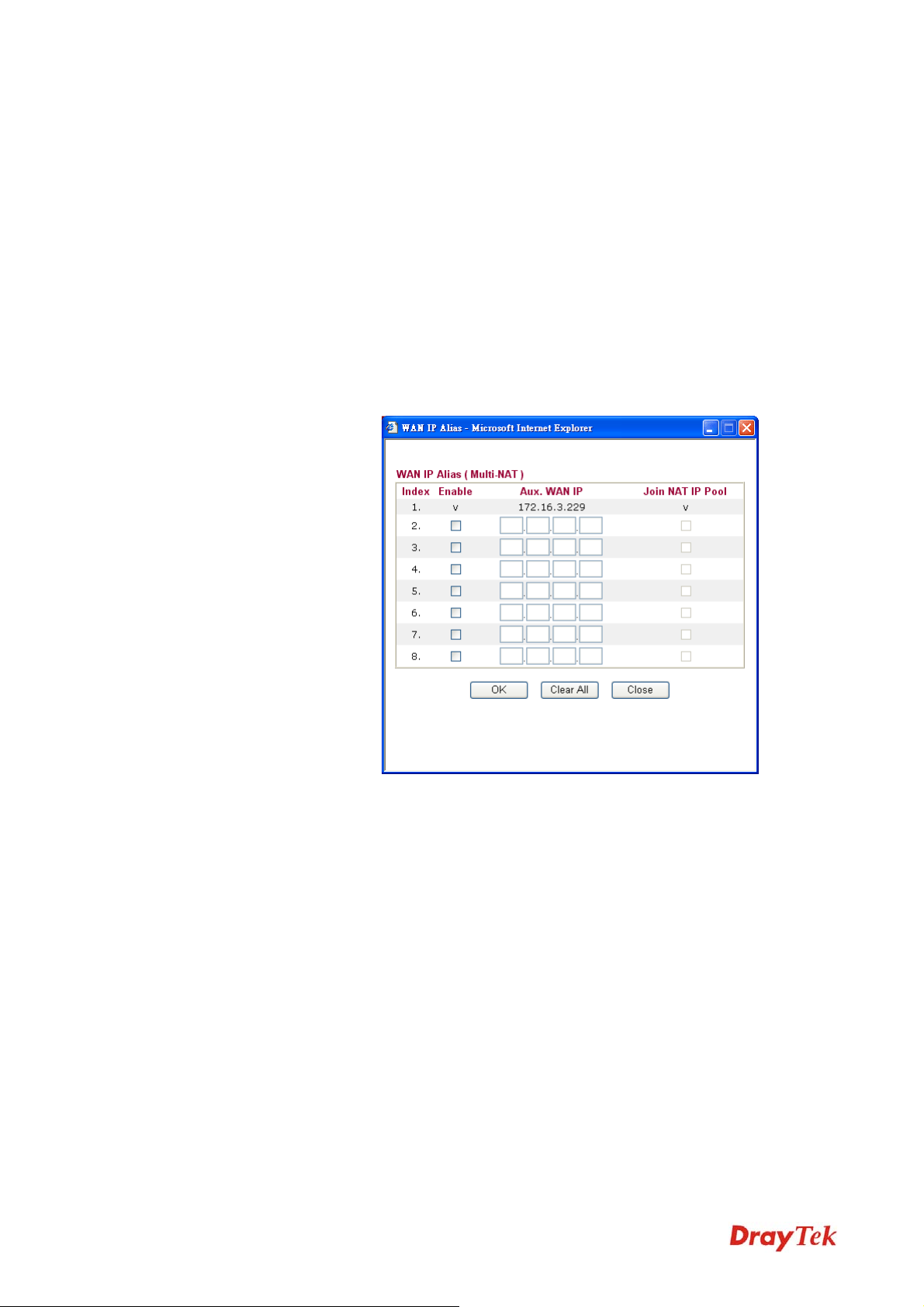
Ping IP – If you choose Ping Detect as detection mode, you have
to type IP address in this field for pinging.
TTL (Time to Live) – Displays value for your reference. TTL
value is set by telnet command.
RIP Protocol
WAN IP Network
Settings
Routing Information Protocol is abbreviated as RIP(RFC1058)
specifying how routers exchange routing tables information. Click
Enable RIP for activating this function.
This group allows you to obtain an IP address automatically and
allows you type in IP address manually.
WAN IP Alias - If you have multiple public IP addresses and
would like to utilize them on the WAN interface, please use
WAN IP Alias. You can set up to 8 public IP addresses other than
the current one you are using.
Obtain an IP address automatically – Click this button to
obtain the IP address automatically if you want to use Dynamic
IP mode.
Router Name: Type in the router name provided by ISP.
Domain Name: Type in the domain name that you have assigned.
Specify an IP address – Click this radio button to specify some
data if you want to use Static IP mode.
IP Address: Type the IP address.
Subnet Mask: Type the subnet mask.
Gateway IP Address: Type the gateway IP address.
Default MAC Address : Click this radio button to use default
MAC address for the router.
Specify a MAC Address: Some Cable service providers specify a
specific MAC address for access authentication. In such cases you
need to click the Specify a MAC Address and enter the MAC
address in the MAC Address field.
Vigor2830 Series User’s Guide
50
Page 63

DNS Server IP Address
Type in the primary IP address for the router if you want to use
Static IP mode. If necessary, type in secondary IP address for
necessity in the future.
After finishing all the settings here, please click OK to activate them.
DDeettaaiillss PPaaggee ffoorr PPPPTTPP//LL22TTPP iinn WWAANN22
To use PPTP/L2TP as the accessing protocol of the internet, please click the PPTP/L2TP tab.
The following web page will be shown.
PPTP/L2TP Client Mode
ISP Access Setup
PPP Setup
IP Address Assignment
Method(IPCP)
Enable PPTP- Click this radio button to enable a PPTP client
to establish a tunnel to a DSL modem on the WAN interface.
Enable L2TP - Click this radio button to enable a L2TP client
to establish a tunnel to a DSL modem on the WAN interface.
Disable – Click this radio button to close the connection
through PPTP or L2TP.
Server Address - Specify the IP address of the PPTP/L2TP
server if you enable PPTP/L2TP client mode.
Specify Gateway IP Address – Specify the gateway IP
address for DHCP server.
Username -Type in the username provided by ISP in this
field.
Password -Type in the password provided by ISP in this field.
PPP Authentication - Select PAP only or PAP or CHAP for
PPP.
Idle Timeout - Set the timeout for breaking down the Internet
after passing through the time without any action.
WAN IP Alias - If you have multiple public IP addresses and
would like to utilize them on the WAN interface, please use
WAN IP Alias. You can set up to 8 public IP addresses other
51
Vigor2830 Series User’s Guide
Page 64

than the current one you are using.
Fixed IP - Usually ISP dynamically assigns IP address to you
each time you connect to it and request. In some case, your
ISP provides service to always assign you the same IP address
whenever you request. In this case, you can fill in this IP
address in the Fixed IP field. Please contact your ISP before
you want to use this function. Click Yes to use this function
and type in a fixed IP address in the box.
Fixed IP Address -Type a fixed IP address.
WAN IP Network
Settings
Obtain an IP address automatically – Click this button to
obtain the IP address automatically.
Specify an IP address – Click this radio button to specify
some data.
IP Address – Type the IP address.
Subnet Mask – Type the subnet mask.
After finishing all the settings here, please click OK to activate them.
Vigor2830 Series User’s Guide
52
Page 65

DDeettaaiillss PPaaggee ffoorr PPPPPP iinn WWAANN33
To use PPP (for 3G USB Modem) as the accessing protocol of the internet, please choose
Internet Access from WAN menu. Then, select PPP mode for WAN2. The following web
page will be shown.
Enable / Disable
SIM PIN code
Modem Initial String
APN Name
Modem Initial String2
Modem Dial String
PPP Username
PPP Password
Click Enable for activating this function. If you click Disable,
this function will be closed and all the settings that you adjusted
in this page will be invalid.
Type PIN code of the SIM card that will be used to access
Internet.
Such value is used to initialize USB modem. Please use the
default value. If you have any question, please contact to your
ISP.
APN means Access Point Name which is provided and required
by some ISPs. Type the name and click Apply.
The initial string 1 is shared with APN.
In some cases, users may need another initial AT command to
restrict 3G band or do any special settings.
Such value is used to dial through USB mode. Please use the
default value. If you have any question, please contact to your
ISP.
Type the PPP username (optional).
Type the PPP password (optional).
WAN Connection
Detection
Such function allows you to verify whether network connection is
alive or not through ARP Detect or Ping Detect.
Mode – Choose ARP Detect or Ping Detect for the system to
53
Vigor2830 Series User’s Guide
Page 66
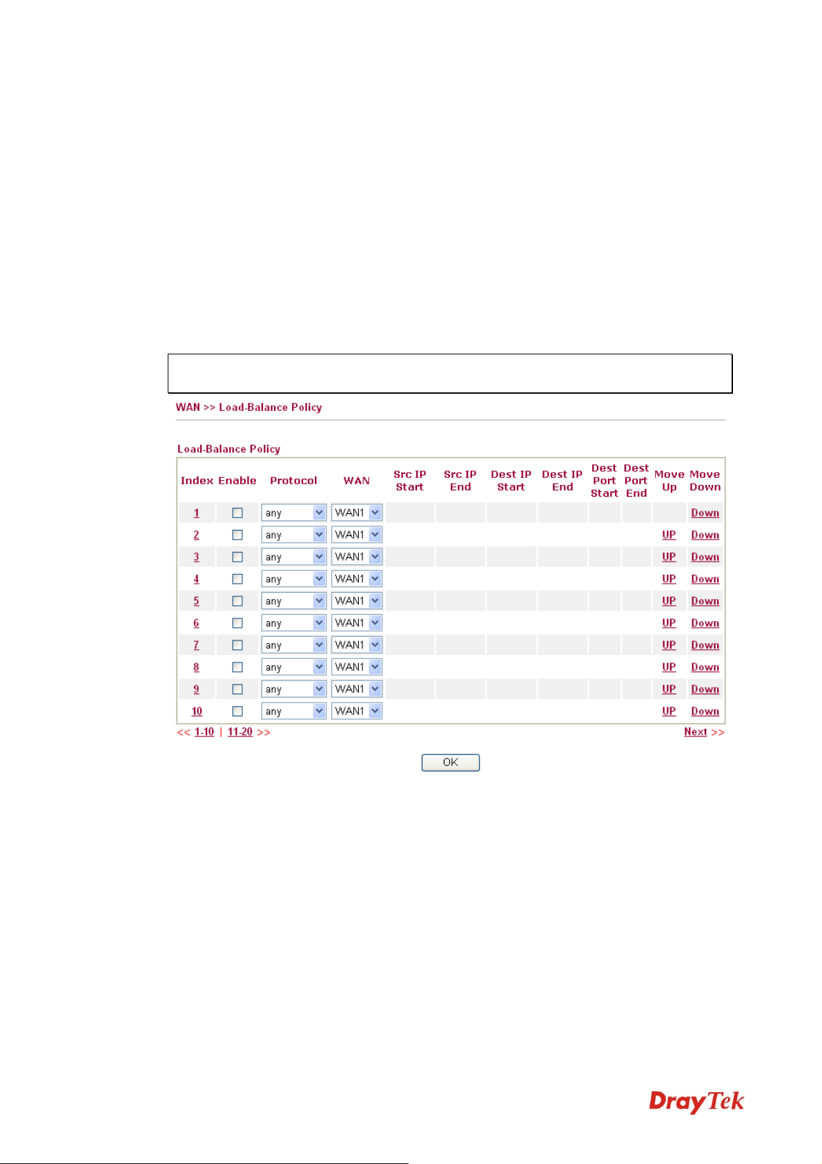
execute for WAN detection.
Ping IP – If you choose Ping Detect as detection mode, you have
to type IP address in this field for pinging.
TTL (Time to Live) – Displays value for your reference. TTL
value is set by telnet command.
After finishing all the settings here, please click OK to activate them.
33..11..44 LLooaadd--BBaallaannccee PPoolliiccyy
This router supports the function of load balancing. It can assign traffic with protocol type, IP
address for specific host, a subnet of hosts, and port range to be allocated in WAN interface.
The user can assign traffic category and force it to go to dedicate network interface based on
the following web page setup. Twenty policies of load-balance are supported by this router.
Note: Load-Balance Policy is running only when more than one WAN interface is
activated.
Index
Enable
Protocol
WAN
Src IP Start
Src IP End
Dest IP Start
Dest IP End
Dest Port Start
Vigor2830 Series User’s Guide
Click the number of index to access into the load-balance policy
configuration web page.
Check this box to enable this policy.
Use the drop-down menu to change the protocol for the WAN
interface.
Use the drop-down menu to change the WAN interface.
Displays the IP address for the start of the source IP
Displays the IP address for the end of the source IP.
Displays the IP address for the start of the destination IP.
Displays the IP address for the end of the destination IP.
Displays the IP address for the start of the destination port.
54
Page 67

Dest Port End
Move UP/Move Down
Displays the IP address for the end of the destination port.
Use Up or Down link to move the order of the policy.
Click Index 1 to access into the following page for configuring load-balance policy.
Enable
Protocol
Binding WAN interface
Src IP Start
Src IP End
Dest IP Start
Check this box to enable this policy.
Use the drop-down menu to choose a proper protocol for the
WAN interface.
Choose the WAN interface (WAN1 / WAN2 / WAN3) for
binding.
Auto failover to other WAN – Check this button to lead the data
passing through other WAN automatically when the selected
WAN interface is failover.
Type the source IP start for the specified WAN interface.
Type the source IP end for the specified WAN interface. If this
field is blank, it means that all the source IPs inside the LAN will
be passed through the WAN interface.
Type the destination IP start for the specified WAN interface.
Dest IP End
Dest Port Start
Dest Port End
Type the destination IP end for the specified WAN interface. If
this field is blank, it means that all the destination IPs will be
passed through the WAN interface.
Type the destination port start for the destination IP.
Type the destination port end for the destination IP. If this field is
blank, it means that all the destination ports will be passed
55
Vigor2830 Series User’s Guide
Page 68

through the WAN interface.
33..22 LLAANN
Local Area Network (LAN) is a group of subnets regulated and ruled by router. The design of
network structure is related to what type of public IP addresses coming from your ISP.
33..22..11 BBaassiiccss ooff LLAANN
The most generic function of Vigor router is NAT. It creates a private subnet of your own. As
mentioned previously, the router will talk to other public hosts on the Internet by using public
IP address and talking to local hosts by using its private IP address. What NAT does is to
translate the packets from public IP address to private IP address to forward the right packets
to the right host and vice versa. Besides, Vigor router has a built-in DHCP server that assigns
private IP address to each local host. See the following diagram for a briefly understanding.
In some special case, you may have a public IP subnet from your ISP such as
220.135.240.0/24. This means that you can set up a public subnet or call second subnet that
each host is equipped with a public IP address. As a part of the public subnet, the Vigor router
will serve for IP routing to help hosts in the public subnet to communicate with other public
hosts or servers outside. Therefore, the router should be set as the gateway for public hosts.
Vigor2830 Series User’s Guide
56
Page 69

WWhhaatt iiss RRoouuttiinngg IInnffoorrmmaattiioonn PPrroottooccooll ((RRIIPP))
Vigor router will exchange routing information with neighboring routers using the RIP to
accomplish IP routing. This allows users to change the information of the router such as IP
address and the routers will automatically inform for each other.
WWhhaatt iiss SSttaattiicc RRoouuttee
When you have several subnets in your LAN, sometimes a more effective and quicker way for
connection is the Static rou tes function rather than other method. You may simply set rules to
forward data from one specified subnet to another specified subnet without the presence of
RIP.
WWhhaatt aarree VViirrttuuaall LLAANNss
You can group local hosts by physical ports and create up to 4 virtual LANs. To manage the
communication between different groups, please set up rules in Virtual LAN (VLAN) function
and the rate of each.
57
Vigor2830 Series User’s Guide
Page 70

33..22..22 GGeenneerraall SSeettuupp
This page provides you the general settings for LAN. Click LAN to open the LAN settings page and choose General Setup.
Index
Status
DHCP
IP Address
Details Page
Display all of the LAN items.
Basically, LAN1 status is enabled in default. LAN2, LAN3,
LAN3 and IP Routed Subnet can be observed by checking the
box of Status.
LAN1 is configured with DHCP in default. If required, please
check the DHCP box for each LAN.
Display the IP address for each LAN item. Such information is
set in default and you can not modify it.
Click it to access into the setting page. Each LAN will have
different LAN configuration page. Each LAN must be
configured in different subnet.
DDeettaaiillss PPaaggee ffoorr LLAANN11
Click Details Page to open the following page.
IP Addr ess
Type in private IP address for connecting to a local private
network (Default: 192.168.1.1).
Subnet Mask
Vigor2830 Series User’s Guide
Type in an address code that determines the size of the network.
(Default: 255.255.255.0/ 24)
58
Page 71

RIP Protocol Control
DHCP Server
Configuration
Disable deactivates the RIP protocol. It will lead to a stoppage
of the exchange of routing information between routers.
(Default)
1st Subnet - Select the router to change the RIP information of
the 1st subnet with neighboring routers.
2nd Subnet - Select the router to change the RIP information of
the 2nd subnet with neighboring routers.
DHCP stands for Dynamic Host Configuration Protocol. The
router by factory default acts a DHCP server for your network so
it automatically dispatch related IP settings to any local user
configured as a DHCP client. It is highly recommended that you
leave the router enabled as a DHCP server if you do not have a
DHCP server for your network.
If you want to use another DHCP server in the network other
than the Vigor Router’s, you can let Relay Agent help you to
redirect the DHCP request to the specified location.
Enable Server - Let the router assign IP address to every host in
the LAN.
Disable Server – Let you manually assign IP address to every
host in the LAN.
Relay Agent –Specify which subnet that DHCP server is located
the relay agent should redirect the DHCP request to.
Start IP Address - Enter a value of the IP address pool for the
DHCP server to start with when issuing IP addresses. If the 1st
IP address of your router is 192.168.1.1, the starting IP address
must be 192.168.1.2 or greater, but smaller than 192.168.1.254.
IP Pool Counts - Enter the maximum number of PCs that you
want the DHCP server to assign IP addresses to. The default is
50 and the maximum is 253.
Gateway IP Address - Enter a value of the gateway IP address
for the DHCP server. The value is usually as same as the 1st IP
address of the router, which means the router is the default
gateway.
DHCP Server IP Address for Relay Agent - Set the IP address
of the DHCP server you are going to use so the Relay Agent can
help to forward the DHCP request to the DHCP server.
DNS Server
Configuration
DNS stands for Domain Name System. Every Internet host must
have a unique IP address, also they may have a human-friendly,
easy to remember name such as www.yahoo.com. The DNS
server converts the user-friendly name into its equivalent IP
address.
Force DNS manual setting -
Force Vigor router to use DNS
servers in this page instead of DNS servers given by the Internet
59
Vigor2830 Series User’s Guide
Page 72

Access server (PPPoE, PPTP, L2TP or DHCP server).
Primary IP Address -You must specify a DNS server IP address
here because your ISP should provide you with usually more
than one DNS Server. If your ISP does not provide it, the router
will automatically apply default DNS Server IP address:
194.109.6.66 to this field.
Secondary IP Address - You can specify secondary DNS server
IP address here because your ISP often provides you more than
one DNS Server. If your ISP does not provide it, the router will
automatically apply default secondary DNS Server IP address:
194.98.0.1 to this field.
The default DNS Server IP address can be found via Online
Status:
33..33 NNAATT
If both the Primary IP and Secondary IP Address fields are left
empty, the router will assign its own IP address to local users as
a DNS proxy server and maintain a DNS cache.
If the IP address of a domain name is already in the DNS cache,
the router will resolve the domain name immediately. Otherwise,
the router forwards the DNS query packet to the external DNS
server by establishing a WAN (e.g. DSL/Cable) connection.
Usually, the router serves as an NAT (Network Address Translation) router. NAT is a
mechanism that one or more private IP addresses can be mapped into a single public one.
Public IP address is usually assigned by your ISP, for which you may get charged. Private IP
addresses are recognized only among internal hosts.
When the outgoing packets destined to some public server on the Internet reach the NAT
router, the router will change its source address into the public IP address of the router, select
the available public port, and then forward it. At the same time, the router shall list an entry in
a table to memorize this address/port-mapping relationship. When the public server response,
the incoming traffic, of course, is destined to the router’s public IP address and the router will
do the inversion based on its table. Therefore, the internal host can communicate with external
host smoothly.
The benefit of the NAT includes:
z Save cost on applying public IP address and apply efficient usage of IP address.
NAT allows the internal IP addresses of local hosts to be translated into one public IP
address, thus you can have only one IP address on behalf of the entire internal hosts.
z Enhance security of the internal network by obscuring the IP address. There are
many attacks aiming victims based on the IP address. Since the attacker cannot be aware
of any private IP addresses, the NAT function can protect the internal network.
On NAT page, you will see the private IP address defined in RFC-1918. Usually we use the
192.168.1.0/24 subnet for the router. As stated before, the NAT facility can map one or
more IP addresses and/or service ports into different specified services. In other words, the
NAT function can be achieved by using port mapping methods.
Vigor2830 Series User’s Guide
60
Page 73

Below shows the menu items for NAT.
33..33..11 PPoorrtt RReeddiirreeccttiioonn
Port Redirection is usually set up for server related service inside the local network (LAN), such as web servers, FTP servers, E-mail servers etc. Most of the case, you need a public IP address for each server and this public IP address/domain name are recognized by all users. Since the server is actually located inside the LAN, the network well protected by NAT of the router, and identified by its private IP address/port, the goal of Port Redirection function is to forward all access request with public IP address from external users to the mapping private IP address/port of the server.
The port redirection can only apply to incoming traffic.
To use this function, please go to NAT page and choose Port Redirection web page. The
Port Redirection Table provides 20 port-mapping entries for the internal hosts.
61
Vigor2830 Series User’s Guide
Page 74
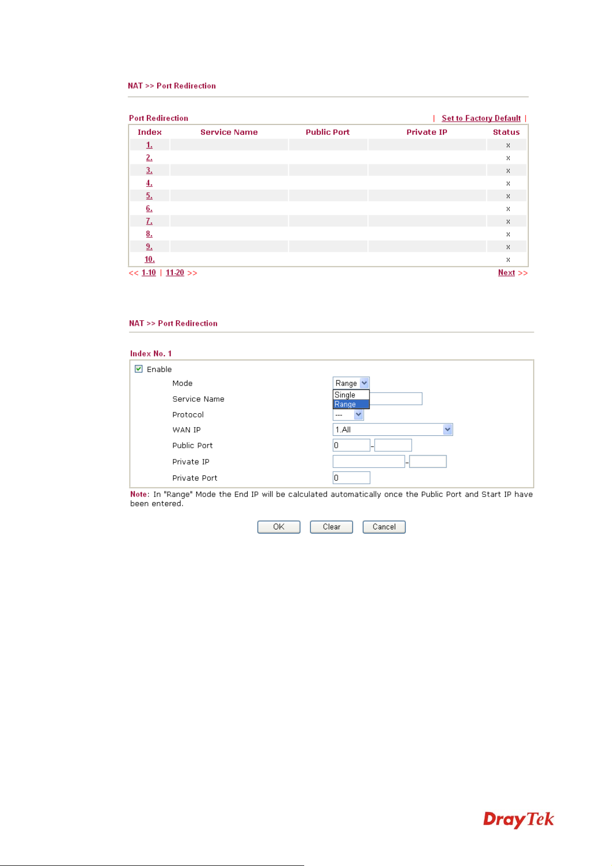
Press any number under Index to access into next page for configuring port redirection.
Enable
Mode
Service Name
Protocol
WAN IP
Public Port
Vigor2830 Series User’s Guide
Check this box to enable such port redirection setting.
Two options (Single and Range) are provided here for you to
choose. To set a range for the specific service, select Range. In
Range mode, if the public port (start port and end port) and the
starting IP of private IP had been entered, the system will
calculate and display the ending IP of private IP automatically.
Enter the description of the specific network service.
Select the transport layer protocol (TCP or UDP).
Select the WAN IP used for port redirection. There are eight
WAN IP alias that can be selected and used for port redirection.
The default setting is All which means all the incoming data
from any port will be redirected to specified range of IP address
and port.
Specify which port can be redirected to the specified Private IP
and Port of the internal host. If you choose Range as the port
62
Page 75

redirection mode, you will see two boxes on this field. Simply
type the required number on the first box. The second one will
be assigned automatically later.
Private IP
Specify the private IP address of the internal host providing the
service. If you choose Range as the port redirection mode, you
will see two boxes on this field. Type a complete IP address in
the first box (as the starting point) and the fourth digits in the
second box (as the end point).
Private Port
Specify the private port number of the service offered by the
internal host
Note that the router has its own built-in services (servers) such as Telnet, HTTP and FTP etc.
Since the common port numbers of these services (servers) are all the same, you may need to
reset the router in order to avoid confliction.
63
Vigor2830 Series User’s Guide
Page 76

33..33..22 DDMMZZ HHoosstt
As mentioned above, Port Redirection can redirect incoming TCP/UDP or other traffic on
particular ports to the specific private IP address/port of host in the LAN. However, other IP
protocols, for example Protocols 50 (ESP) and 51 (AH), do not travel on a fixed port. Vigor
router provides a facility DMZ Host that maps ALL unsolicited data on any protocol to a
single host in the LAN. Regular web surfing and other such Internet activities from other
clients will continue to work without inappropriate interruption. DMZ Host allows a defined
internal user to be totally exposed to the Internet, which usually helps some special
applications such as NetMeeting or Internet Games etc.
Note: The security properties of NAT are somewhat bypassed if you set up DMZ host. We
suggest you to add additional filter rules or a secondary firewall.
Click DMZ Host to open the following page:
DMZ Host for WAN2 and WAN3 is slightly different with WAN1. See the following figure.
Vigor2830 Series User’s Guide
64
Page 77
If you previously have set up WAN Alias for PPPoE or Static or Dynamic IP mode in
WAN2 interface, you will find them in Aux. WAN IP for your selection.
Enable
Private IP
Choose PC
Check to enable the DMZ Host function.
Enter the private IP address of the DMZ host, or click Choose PC
to select one.
Click this button and then a window will automatically pop up, as
depicted below. The window consists of a list of private IP
addresses of all hosts in your LAN network. Select one private IP
address in the list to be the DMZ host.
When you have selected one private IP from the above dialog, the
IP address will be shown on the following screen. Click OK to
save the setting.
65
Vigor2830 Series User’s Guide
Page 78
33..33..33 OOppeenn PPoorrttss
Open Ports allows you to open a range of ports for the traffic of special applications. Common application of Open Ports includes P2P application (e.g., BT, KaZaA, Gnutella,
WinMX, eMule and others), Internet Camera etc. Ensure that you keep the application
involved up-to-date to avoid falling victim to any security exploits.
Click Open Ports to open the following page:
Index
Indicate the relative number for the particular entry that you
want to offer service in a local host. You should click the
appropriate index number to edit or clear the corresponding
entry.
Comment
WAN Interface
Aux. WAN IP
Local IP Address
Specify the name for the defined network service.
Display the WAN interface for such NAT profile.
Display the WAN IP address specified in WAN IP Alias page.
Display the private IP address of the local host offering the
service.
Status
Display the state for the corresponding entry. X or V is to
represent the Inactive or Active state.
To add or edit port settings, click one index number on the page. The index entry setup page
will pop up. In each index entry, you can specify 20 port ranges for diverse services.
Vigor2830 Series User’s Guide
66
Page 79
Enable Open Ports
Check to enable this entry.
Comment
WAN Interface
Local Computer
Choose PC
Protocol
Start Port
End Port
Make a name for the defined network application/service.
Specify the WAN interface that will be used for this entry.
Enter the private IP address of the local host or click Choose
PC to select one.
Click this button and, subsequently, a window having a list of
private IP addresses of local hosts will automatically pop up.
Select the appropriate IP address of the local host in the list.
Specify the transport layer protocol. It could be TCP, UDP, or
----- (none) for selection.
Specify the starting port number of the service offered by the
local host.
Specify the ending port number of the service offered by the
local host.
67
Vigor2830 Series User’s Guide
Page 80

33..44 AApppplliiccaattiioonnss
Below shows the menu items for Applications.
33..44..11 DDyynnaammiicc DDNNSS
The ISP often provides you with a dynamic IP address when you connect to the Internet via
your ISP. It means that the public IP address assigned to your router changes each time you
access the Internet. The Dynamic DNS feature lets you assign a domain name to a dynamic
WAN IP address. It allows the router to update its online WAN IP address mappings on the
specified Dynamic DNS server. Once the router is online, you will be able to use the
registered domain name to access the router or internal virtual servers from the Internet. It is
particularly helpful if you host a web server, FTP server, or other server behind the router.
Before you use the Dynamic DNS feature, you have to apply for free DDNS service to the
DDNS service providers. The router provides up to three accounts from three different DDNS
service providers. Basically, Vigor routers are compatible with the DDNS services supplied by
most popular DDNS service providers such as www.dyndns.org, www.no-ip.com,
www.dtdns.com, www.changeip.com, www.dynamic- nameserver.com. You should visit
their websites to register your own domain name for the router.
Enable the Function and Add a Dynamic DNS Account
1. Assume you have a registered domain name from the DDNS provider, say
hostname.dyndns.org, and an account with username: test and password: test.
2. In the DDNS setup menu, check Enable Dynamic DNS Setup.
Enable Dynamic DNS
Setup
Set to Factory Default
Auto-Update interval
Check this box to enable DDNS function.
Clear all profiles and recover to factory settings.
Set the time for the router to perform auto update for
DDNS service.
Index
WAN Interface
Domain Name
Vigor2830 Series User’s Guide
Click the number below Index to access into the setting
page of DDNS setup to set account(s).
Display the WAN interface used.
Display the domain name that you set on the setting page
of DDNS setup.
68
Page 81
Active
View Log
Force Update
Display if this account is active or inactive.
Display DDNS log status.
Force the router updates its information to DDNS server.
3. Select Index number 1 to add an account for the router. Check Enable Dynamic DNS
Account, and choose correct Service Provider: dyndns.org, type the registered hostname:
hostname and domain name suffix: dyndns.org in the Domain Name block. The
following two blocks should be typed your account Login Name: test and Password: test.
Enable Dynamic DNS
Account
WAN Interface
Service Provider
Service Type
Check this box to enable the current account. If you did
check the box, you will see a check mark appeared on the
Active column of the previous web page in step 2).
WAN1/WAN2/WAN3 First - While connecting, the
router will use WAN1/WAN2/WAN3 as the first channel
for such account. If WAN1/WAN2/WAN3 fails, the
router will use another WAN interface instead.
WAN1/WAN2/WAN3 Only - While connecting, the
router will use WAN1/WAN2/WAN3 as the only channel
for such account.
Select the service provider for the DDNS account.
Select a service type (Dynamic, Custom or Static). If you
choose Custom, you can modify the domain that is chosen
in the Domain Name field.
Domain Name
Login Name
Type in one domain name that you applied previously.
Use the drop down list to choose the desired domain.
Type in the login name that you set for applying domain.
69
Vigor2830 Series User’s Guide
Page 82

4. Click OK button to activate the settings. You will see your setting has been saved.
Disable the Function and Clear all Dynamic DNS Accounts
In the DDNS setup menu, uncheck Enable Dynamic DNS Setup, and push Clear All button
to disable the function and clear all accounts from the router.
Delete a Dynamic DNS Account
In the DDNS setup menu, click the Index number you want to delete and then push Clear All
button to delete the account.
33..44..22 UUPPnnPP
The UPnP (Universal Plug and Play) protocol is supported to bring to network connected devices the ease of installation and configuration which is already available for directly connected PC peripherals with the existing Windows 'Plug and Play' system. For NAT routers, the major feature of UPnP on the router is “NAT Traversal”. This enables applications inside the firewall to automatically open the ports that they need to pass through a router. It is more reliable than requiring a router to work out by itself which ports need to be opened. Further, the user does not have to manually set up port mappings or a DMZ. UPnP is available on Windows XP and the router provide the associated support for MSN Messenger to allow full use of the voice, video and messaging features.
Password
Wildcard and Backup
MX
Type in the password that you set for applying domain.
The Wildcard and Backup MX features are not supported
for all Dynamic DNS providers. You could get more
detailed information from their websites.
Enable UPNP Service
After setting Enable UPNP Service setting, an icon of IP Broadband Connection on Router
on Windows XP/Network Connections will appear. The connection status and control status
will be able to be activated. The NAT Traversal of UPnP enables the multimedia features of
your applications to operate. This has to manually set up port mappings or use other similar
methods. The screenshots below show examples of this facility.
Vigor2830 Series User’s Guide
Accordingly, you can enable either the Connection Control
Service or Connection Status Service.
70
Page 83

The UPnP facility on the router enables UPnP aware applications such as MSN Messenger to
discover what are behind a NAT router. The application will also learn the external IP address
and configure port mappings on the router. Subsequently, such a facility forwards packets from
the external ports of the router to the internal ports used by the application.
The reminder as regards concern about Firewall and UPnP
Can't work with Firewall Software
Enabling firewall applications on your PC may cause the UPnP function not working
properly. This is because these applications will block the accessing ability of some network
ports.
Security Considerations
Activating the UPnP function on your network may incur some security threats. You should
consider carefully these risks before activating the UPnP function.
¾ Some Microsoft operating systems have found out the UPnP weaknesses and hence
you need to ensure that you have applied the latest service packs and patches.
¾ Non-privileged users can control some router functions, including removing and
adding port mappings.
71
Vigor2830 Series User’s Guide
Page 84

The UPnP function dynamically adds port mappings on behalf of some UPnP-aware
applications. When the applications terminate abnormally, these mappings may not be
removed.
33..55 WWiirreelleessss LLAANN
This function is used for “n” models.
33..55..11 BBaassiicc CCoonncceeppttss
Over recent years, the market for wireless communications has enjoyed tremendous growth.
Wireless technology now reaches or is capable of reaching virtually every location on the
surface of the earth. Hundreds of millions of people exchange information every day via
wireless communication products. The Vigor “n” model, a.k.a. Vigor wireless router, is
designed for maximum flexibility and efficiency of a small office/home. Any authorized staff
can bring a built-in WLAN client PDA or notebook into a meeting room for conference
without laying a clot of LAN cable or drilling holes everywhere. Wireless LAN enables high
mobility so WLAN users can simultaneously access all LAN facilities just like on a wired
LAN as well as Internet access
The Vigor wireless routers are equipped with a wireless LAN interface compliant with the
standard IEEE 802.11n draft 2 protocol. To boost its performance further, the Vigor Router is
also loaded with advanced wireless technology to lift up data rate up to 300 Mbps*. Hence,
you can finally smoothly enjoy stream music and video.
Note:
* The actual data throughput will vary according to the network conditions and
environmental factors, including volume of network traffic, network overhead and
building materials.
In an Infrastructure Mode of wireless network, Vigor wireless router plays a role as an Access
Point (AP) connecting to lots of wireless clients or Stations (STA). All the STAs will share the
same Internet connection via Vigor wireless router. The General Settings will set up the
information of this wireless network, including its SSID as identification, located channel etc.
Vigor2830 Series User’s Guide
72
Page 85

SSeeccuurriittyy OOvveerrvviieeww
Real-time Hardware Encryption: Vigor Router is equipped with a hardware AES encryption
engine so it can apply the highest protection to your data without influencing user experience.
Complete Security Standard Selection: To ensure the security and privacy of your wireless
communication, we provide several prevailing standards on market.
WEP (Wired Equivalent Privacy) is a legacy method to encrypt each frame transmitted via
radio using either a 64-bit or 128-bit key. Usually access point will preset a set of four keys
and it will communicate with each station using only one out of the four keys.
WPA (Wi-Fi Protected Access), the most dominating security mechanism in industry, is
separated into two categories: WPA-personal or called WPA Pre-Share Key (WPA/PSK), and
WPA-Enterprise or called WPA/802.1x.
In WPA-Personal, a pre-defined key is used for encryption during data transmission. WPA
applies Temporal Key Integrity Protocol (TKIP) for data encryption while WPA2 applies AES.
The WPA-Enterprise combines not only encryption but also authentication.
Since WEP has been proved vulnerable, you may consider using WPA for the most secure
connection. You should select the appropriate security mechanism according to your needs.
No matter which security suite you select, they all will enhance the over-the-air data
protection and /or privacy on your wireless network. The Vigor wireless router is very flexible
and can support multiple secure connections with both WEP and WPA at the same time.
Separate the Wireless and the Wired LAN- WLAN Isolation enables you to isolate your
wireless LAN from wired LAN for either quarantine or limit access reasons. To isolate means
neither of the parties can access each other. To elaborate an example for business use, you
may set up a wireless LAN for visitors only so they can connect to Internet without hassle of
the confidential information leakage. For a more flexible deployment, you may add filters of
MAC addresses to isolate users’ access from wired LAN.
Manage Wireless Stations - Station List will display all the station in your wireless network
and the status of their connection.
Below shows the menu items for Wireless LAN.
73
Vigor2830 Series User’s Guide
Page 86

33..55..22 GGeenneerraall SSeettuupp
By clicking the General Settings, a new web page will appear so that you could configure the
SSID and the wireless channel. Please refer to the following figure for more information.
Enable Wireless LAN
Mode
SSID
Channel
Check the box to enable wireless function.
At present, the router can connect to 11n Only, 11g Only,
Mixed (11b+11g), Mixed (11a+11n), Mixed (11g+11n), and
Mixed (11b+11g+11n) stations simultaneously. Simply choose
Mix (11b+11g+11n) mode.
In which, the transmission rate for 11a can reach 5G; for
11b/11g can reach 2.4G.
Means the identification of the wireless LAN. SSID can be any
text numbers or various special characters. The default SSID is
"DrayTek". We suggest you to change it.
Means the channel of frequency of the wireless LAN. The
default channel is 6. You may switch channel if the selected
channel is under serious interference. If you have no idea of
choosing the frequency, please select Auto to let system
determine for you.
Vigor2830 Series User’s Guide
74
Page 87

Packet-OVERDRIVE
This feature can enhance the performance in data transmission
about 40%* more (by checking Tx Burst). It is active only
when both sides of Access Point and Station (in wireless client)
invoke this function at the same time. That is, the wireless
client must support this feature and invoke the function, too.
Hide SSID
Note: Vigor N61 wireless adapter supports this function.
Therefore, you can use and install it into your PC for matching
with Packet-OVERDRIVE (refer to the following picture of
Vigor N61 wireless utility window, choose Enable for
TxBURST on the tab of Option).
Check it to prevent from wireless sniffing and make it harder
for unauthorized clients or STAs to join your wireless LAN.
Depending on the wireless utility, the user may only see the
information except SSID or just cannot see any thing about
Vigor wireless router while site surveying. The system allows
you to set four sets of SSID for different usage. In default, the
first set of SSID will be enabled. You can hide it for your
necessity.
Long Preamble
This option is to define the length of the sync field in an 802.11
75
Vigor2830 Series User’s Guide
Page 88

packet. Most modern wireless network uses short preamble
with 56 bit sync field instead of long preamble with 128 bit
sync field. However, some original 11b wireless network
devices only support long preamble. Check it to use Long
Preamble if needed to communicate with this kind of devices.
33..55..33 SSeeccuurriittyy
By clicking the Security Settings, a new web page will appear so that you could configure the
settings of WEP and WPA.
The default security mode is Mixed (WPA+WPA2)/PSK. Default Pre-Shared Key (PSK) is
provided and stated on the label pasted on the bottom of the router. For the wireless client who
wants to access into Internet through such router, please input the default PSK value for
connection.
Mode
Vigor2830 Series User’s Guide
There are several modes provided for you to choose.
Disable - Turn off the encryption mechanism.
WEP-Accepts only WEP clients and the encryption key should
be entered in WEP Key.
WPA/PSK-Accepts only WPA clients and the encryption key
should be entered in PSK.
76
Page 89

WPA2/PSK-Accepts only WPA2 clients and the encryption
key should be entered in PSK.
Mixed (WPA+ WPA2)/PSK - Accepts WPA and WPA2
clients simultaneously and the encryption key should be
entered in PSK.
WPA
WEP
The WPA encrypts each frame transmitted from the radio
using the key, which either PSK (Pre-Shared Key) entered
manually in this field below or automatically negotiated via
802.1x authentication. Either 8~63 ASCII characters, such as
012345678(or 64 Hexadecimal digits leading by 0x, such as
"0x321253abcde...").
Type - Select from Mixed (WPA+WPA2) or WPA2 only.
Pre-Shared Key (PSK) - Either 8~63 ASCII characters, such
as 012345678..(or 64 Hexadecimal digits leading by 0x, such
as "0x321253abcde...").
64-Bit - For 64 bits WEP key, either 5 ASCII characters, such
as 12345 (or 10 hexadecimal digitals leading by 0x, such as
0x4142434445.)
128-Bit -
For 128 bits WEP key, either 13 ASCII characters,
such as ABCDEFGHIJKLM (or 26 hexadecimal digits leading
by 0x, such as 0x4142434445464748494A4B4C4D).
All wireless devices must support the same WEP encryption bit
size and have the same key. Four keys can be entered here, but
only one key can be selected at a time. The keys can be entered
in ASCII or Hexadecimal. Check the key you wish to use.
77
Vigor2830 Series User’s Guide
Page 90
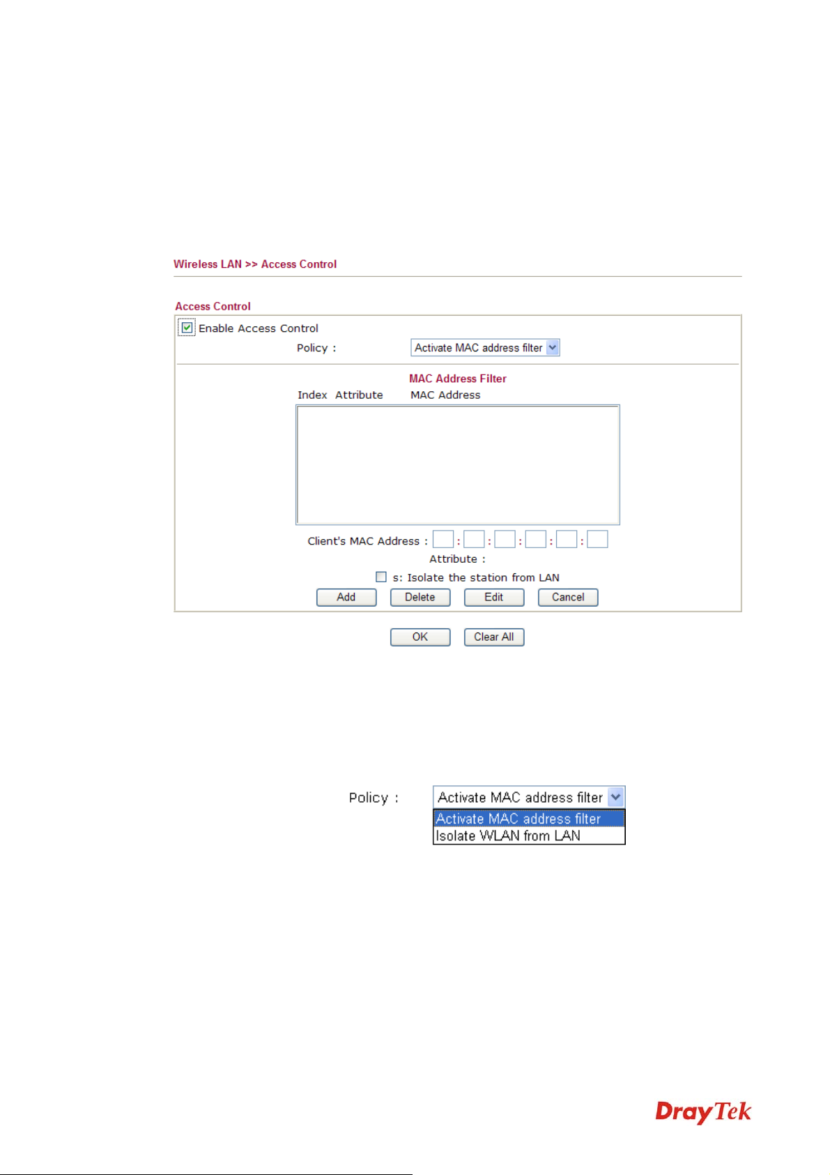
33..55..44 AAcccceessss CCoonnttrrooll
For additional security of wireless access, the Access Control facility allows you to restrict the network access right by controlling the wireless LAN MAC address of client. Only the valid MAC address that has been configured can access the wireless LAN interface. By clicking the Access Control, a new web page will appear, as depicted below, so that you could edit the clients' MAC addresses to control their access rights.
Enable Access Control
Policy
MAC Address Filter
Client’s MAC Address
Attribute
Add
Delete
Edit
Select to enable the MAC Address access control feature.
Select to enable any one of the following policy. Choose
Activate MAC address filter to type in the MAC addresses
for other clients in the network manually. Choose Isolate
WLAN from LAN will separate all the WLAN stations from
LAN based on the MAC Address list.
Display all MAC addresses that are edited before.
Manually enter the MAC address of wireless client.
s: Isolate the station from LAN - select to isolate the wireless
connection of the wireless client of the MAC address from
LAN.
Add a new MAC address into the list.
Delete the selected MAC address in the list.
Edit the selected MAC address in the list.
Vigor2830 Series User’s Guide
78
Page 91

Cancel
OK
Clear All
33..55..55 SSttaattiioonn LLiisstt
Station List provides the knowledge of connecting wireless clients now along with its status code. There is a code summary below for explanation. For convenient Access Control, you can select a WLAN station and click Add to Access Control below.
Give up the access control set up.
Click it to save the access control list.
Clean all entries in the MAC address list.
Refresh
Add
Click this button to refresh the status of station list.
Click this button to add current typed MAC address into
Access Control.
79
Vigor2830 Series User’s Guide
Page 92

33..66 UUSSBB AApppplliiccaattiioonn
USB storage disk connected on Vigor router can be regarded as a server. By way of Vigor router, clients on LAN/WAN can access, write and read data stored in USB storage disk with different applications. After setting the configuration in USB Application, you can type the IP address of the Vigor router and username/password created in USB Application>>USB User Management on the client software. Then, the client can use the FTP site (USB storage disk) or share the Samba service through Vigor router.
33..66..11 UUSSBB GGeenneerraall SSeettttiinnggss
This page will determine the number of concurrent FTP connection, default charset for FTP
server and enable Samba service. At present, the Vigor router can support USB storage disk
with formats of FAT16 and FAT32 only. Therefore, before connecting the USB diskette into
the Vigor router, please make sure the memory format for the USB storage disk is FAT16 or
FAT32. It is recommended for you to use FAT32 for viewing the filename completely
(FAT16 cannot support long filename).
General Settings
Vigor2830 Series User’s Guide
Simultaneous FTP Connection - This field is used to specify
the quantity of the FTP sessions. The router allows up to 6 FTP
sessions connecting to USB storage diskette at one time.
Default Charset - At present, Vigor router supports three types
of character sets: default, GB2312 and BIG5.
80
Page 93

Default Charset is for English based file name. For Simplified
Chinese file/directory names, please choose GB2312; for
Traditional Chinese file/directory names, choose BIG5.
Samba Service Settings
NetBios Name Service
Click Enable to invoke samba service via the router.
For the NetBios service of USB storage disk, you have to
specify a workgroup name and a host name. A workgroup name
must not be the same as the host name. The workgroup name
can have as many as 15 characters and the host name can have
as many as 23 characters. Both them cannot contain any of the
following--- ; : " < > * + = \ | ?.
Workgroup Name – Type a name for the workgroup.
Host Name – Type the host name for the router.
33..66..22 UUSSBB UUsseerr MMaannaaggeemmeenntt
This page allows you to set profiles for FTP/Samba users. Any user who wants to access into
the USB diskette must type the same username and password configured in this page. Before
adding or modifying settings in this page, please insert a USB diskette first. Otherwise, an
error message will appear to warn you.
Click index number to access into configuration page.
FTP/Samba User
Enable – Click this button to activate this profile (account) for
81
Vigor2830 Series User’s Guide
Page 94
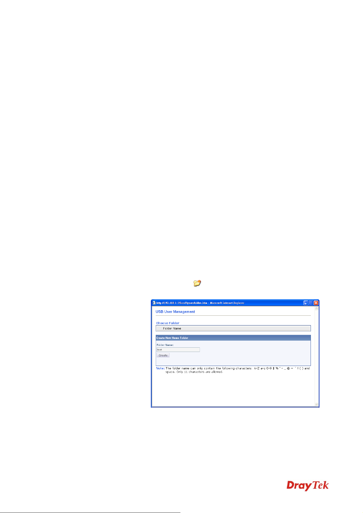
FTP service or Samba User service. Later, the user can use the
username specified in this page to login into FTP server.
Disable – Click this button to disable such profile.
Username
Password
Confirm Password
Home Folder
Type the username for FTP/Samba users for accessing into FTP
server (USB storage disk). Be aware that users cannot access
into USB storage disk in anonymity. Later, you can open FTP
client software and type the username specified here for
accessing into USB storage disk.
Note: “Admin” could not be typed here as username, for the
word is specified for accessing into web pages of Vigor router
only. Also, it is reserved for FTP firmware upgrade usage.
Note: FTP Passive mode is not supported by Vigor Router.
Please disable the mode on the FTP client.
Type the password for FTP/Samba users for accessing FTP
server. Later, you can open FTP client software and type the
password specified here for accessing into USB storage disk.
Type the password again to make confirmation.
It determines the folder for the client to access into.
The user can enter a directory name in this field. Then, after
clicking OK, the router will create the specific/new folder in
the USB storage disk. In addition, if the user types “/” here,
he/she can access into all of the disk folders and files in USB
diskette.
Note: When write protect status for the USB diskette is ON,
you cannot type any new folder name in this field. Only “/” can
be used in such case.
Access Rule
You can click
to open the following dialog to add any new
folder which can be specified as the Home Folder.
It determines the authority for such profile. Any user, who uses
such profile for accessing into USB storage disk, must follow
the rule specified here.
File – Check the items (Read, Write and Delete) for such
profile.
Vigor2830 Series User’s Guide
Directory –Check the items (List, Create and Remove) for such
82
Page 95
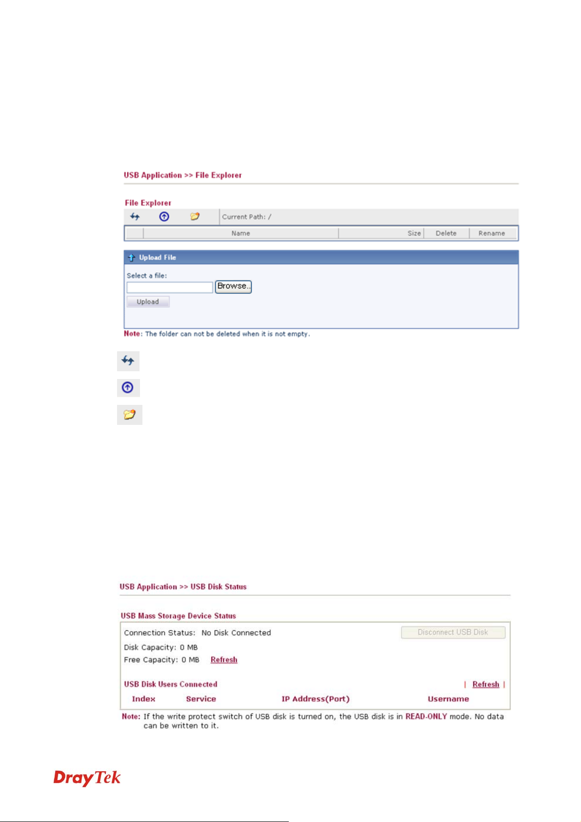
profile.
Before you click OK, you have to insert a USB storage disk into the USB interface of the
Vigor router. Otherwise, you cannot save the configuration.
33..66..33 FFiillee EExxpplloorreerr
File Explorer offers an easy way for users to view and manage the content of USB storage disk
connected on Vigor router.
Refresh
Back
Click this icon to refresh files list.
Click this icon to return to the upper directory.
Create
Current Path
Upload
33..66..44 UUSSBB DDiisskk SSttaattuuss
This page is to monitor the status for the users who accessing into FTP or Samba server (USB
storage disk) via the Vigor router. If you want to remove the diskette from USB port in router,
please click Disconnect USB Disk first. And then, remove the USB storage disk later.
Click this icon to add a new folder.
Display current folder.
Click this button to upload the selected file to the USB storage
disk. The uploaded file in the USB storage disk can be shared
for other user through FTP.
83
Vigor2830 Series User’s Guide
Page 96

Connection Status
Disk Capacity
Free Capacity
Index
IP Address
Username
When you insert USB storage disk into the Vigor router, the system will start to find out such
device within several seconds.
33..66..55 SSyysslloogg EExxpplloorreerr
Such page provides real-time syslog and displays the information on the screen.
If there is no USB storage disk connected to Vigor router, “No
Disk Connected” will be shown here.
It displays the total capacity of the USB storage disk.
It displays the free space of the USB storage disk. Click
Refresh at any time to get new status for free capacity.
It displays the number of the client which connecting to FTP
server.
It displays the IP address of the user’s host which connecting to
the FTP server.
It displays the username that user uses to login to the FTP
server.
FFoorr WWeebb SSyysslloogg
This page displays the time and message for User/Firewall/call/WAN/VPN settings. You can
check Enable Web Syslog, specify the type of Syslog and choose the display mode you want.
Later, the event of Syslog with specified type will be shown for your reference.
Enable Web Syslog
Syslog Type
Display Mode
Check this box to enable the function of Web Syslog.
Use the drop down list to specify a type of Syslog to be
displayed.
There are two modes for you to choose.
Stop record when fulls – when the capacity of syslog is full,
the system will stop recording.
Vigor2830 Series User’s Guide
Always record the new event – only the newest events will be
84
Page 97

recorded by the system.
Time
Message
FFoorr UUSSBB SSyysslloogg
This page displays the syslog recorded on the USB storage disk.
Time
Log Type
Message
Display the time of the event occurred.
Display the information for each event.
Display the time of the event occurred.
Display the type of the record.
Display the information for each event.
33..77 SSyysstteemm MMaaiinntteennaannccee
For the system setup, there are several items that you have to know the way of configuration:
Status, User Password, Time setup and Reboot System.
Below shows the menu items for System Maintenance.
33..77..11 SSyysstteemm SSttaattuuss
The System Status provides basic network settings of Vigor router. It includes LAN and WAN interface information. Also, you could get the current running firmware version or firmware related information from this presentation.
85
Vigor2830 Series User’s Guide
Page 98

Model Name
Display the model name of the router.
Firmware Version
Build Date/Time
LAN-------
LAN1/LAN2/LAN3/LAN4
IP Routed Subnet
MAC Address
IP Address
Subnet Mask
DHCP Server
DNS
Wireless LAN-------
MAC Address
Frequency Domain
Display the firmware version of the router.
Display the date and time of the current firmware build.
There are four LAN ports with different IP address offered by
Vigor router. The MAC address, IP address, Subnet Mask,
DHCP Server and DNS settings for each LAN port is displayed.
Display the general information for the usage of IP routed.
Display the MAC address of the LAN Interface.
Display the IP address of the LAN interface.
Display the subnet mask address of the LAN interface.
Display the current status of DHCP server of the LAN
interface.
Display the assigned IP address of the primary DNS.
Display the MAC address of the wireless LAN.
It can be Europe (13 usable channels), USA (11 usable
channels) etc. The available channels supported by the wireless
products in different countries are various.
Firmware Version
SSID
WAN-------
Link Status
MAC Address
Vigor2830 Series User’s Guide
It indicates information about equipped WLAN miniPCi card.
This also helps to provide availability of some features that are
bound with some WLAN miniPCi.
Display the SSID of the router.
Display current connection status.
Display the MAC address of the WAN Interface.
86
Page 99

Connection
IP Address
Default Gateway
33..77..22 UUsseerr PPaasssswwoorrdd
This page allows you to set new password for user operation.
Old Password
New Password
Display the connection type.
Display the IP address of the WAN interface.
Display the assigned IP address of the default gateway.
Type in the old password. The factory default setting for
password is blank.
Type in new password in this field.
Confirm Password
When you click OK, the login window will appear. Please use the new password to access
into the web configurator again.
33..77..33 TTiimmee aanndd DDaattee
It allows you to specify where the time of the router should be inquired from.
Current System Time
Type in the new password again.
Click Inquire Time to get the current time.
Use Browser Time
Use Internet Time
Select this option to use the browser time from the remote
administrator PC host as router’s system time.
Select to inquire time information from Time Server on the
Internet using assigned protocol.
87
Vigor2830 Series User’s Guide
Page 100
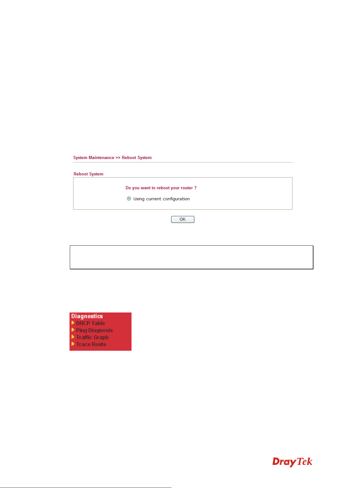
Time Protocol
Server IP Address
Time Zone
Enable Daylight Saving
Automatically Update
Interval
Click OK to save these settings.
33..77..44 RReebboooott SSyysstteemm
The Web Configurator may be used to restart your router for using current configuration. Click Reboot System from System Maintenance to open the following page.
Select a time protocol.
Type the IP address of the time server.
Select the time zone where the router is located.
Check the box to activate daylight saving function. Such feature
is useful for some areas.
Select a time interval for updating from the NTP server.
Click OK. The router will take 5 seconds to reboot the system.
Note: When the system pops up Reboot System web page after you configure web settings,
please click OK to reboot your router for ensuring normal operation and preventing
unexpected errors of the router in the future.
33..88 DDiiaaggnnoossttiiccss
Diagnostic Tools provide a useful way to view or diagnose the status of your Vigor router.
Below shows the menu items for Diagnostics.
Vigor2830 Series User’s Guide
88
 Loading...