

Page 1

Page 2

Vigor2762 Series
ADSL2/2+ & VDSL2 Router
User’s Guide
Version: 1.0
Firmware Version: V3.8.8
(For future update, please visit DrayTek web site)
Date: March 16, 2018
ii
Vigor2762 Series User’s Guide
Page 3

Copyrights
© All rights reserved. This publication contains information that is protected by copyright. No part may be
reproduced, transmitted, transcribed, stored in a retrieval system, or translated into any language without
written permission from the copyright holders.
Trademarks
The following trademarks are used in this document:
Microsoft is a registered trademark of Microsoft Corp.
Windows, Windows 95, 98, Me, NT, 2000, XP, Vista, 7, 8, 10 and Explorer are trademarks of Microsoft Corp.
Apple and Mac OS are registered trademarks of Apple Inc.
Other products may be trademarks or registered trademarks of their respective manufacturers.
Safety Instructions
Read the installation guide thoroughly before you set up the router.
The router is a complicated electronic unit that may be repaired only be authorized and qualified personnel.
Do not try to open or repair the router yourself.
Do not place the router in a damp or humid place, e.g. a bathroom.
The router should be used in a sheltered area, within a temperature range of +5 to +40 Celsius.
Do not expose the router to direct sunlight or other heat sources. The housing and electronic components
may be damaged by direct sunlight or heat sources.
Do not deploy the cable for LAN connection outdoor to prevent electronic shock hazards.
Keep the package out of reach of children.
When you want to dispose of the router, please follow local regulations on conservation of the environment.
Warranty
We warrant to the original end user (purchaser) that the router will be free from any defects in workmanship
or materials for a period of two (2) years from the date of purchase from the dealer. Please keep your
purchase receipt in a safe place as it serves as proof of date of purchase. During the warranty period, and upon
proof of purchase, should the product have indications of failure due to faulty workmanship and/or materials,
we will, at our discretion, repair or replace the defective products or components, without charge for either
parts or labor, to whatever extent we deem necessary tore-store the product to proper operating condition.
Any replacement will consist of a new or re-manufactured functionally equivalent product of equal value, and
will be offered solely at our discretion. This warranty will not apply if the product is modified, misused,
tampered with, damaged by an act of God, or subjected to abnormal working conditions. The warranty does
not cover the bundled or licensed software of other vendors. Defects which do not significantly affect the
usability of the product will not be covered by the warranty. We reserve the right to revise the manual and
online documentation and to make changes from time to time in the contents hereof without obligation to
notify any person of such revision or changes.
Be a Registered Owner
Web registration is preferred. You can register your Vigor router via http://www.DrayTek.com.
Firmware & Tools Updates
Due to the continuous evolution of DrayTek technology, all routers will be regularly upgraded. Please consult
the DrayTek web site for more information on newest firmware, tools and documents.
http://www.DrayTek.com
Vigor2762 Series User’s Guide
iii
Page 4

iv
Vigor2762 Series User’s Guide
Page 5

TTaabbllee ooff CCoonntteennttss
Part I Installation................................................................................................................1
I-1 Introduction ................................................................................................................................... 2
I-1-1 Indicators and Connectors .................................................................................................. 3
I-2 Hardware Installation .................................................................................................................... 6
I-2-1 Installing Vigor Router......................................................................................................... 6
I-2-2 Wall-Mounted Installation.................................................................................................... 7
I-2-3 Installing USB Printer to Vigor Router................................................................................. 8
I-3 Accessing Web Page.................................................................................................................. 16
I-4 Changing Password.................................................................................................................... 18
I-5 Dashboard................................................................................................................................... 19
I-5-1 Virtual Panel...................................................................................................................... 19
I-5-2 Name with a Link............................................................................................................... 20
I-5-3 Quick Access for Common Used Menu ............................................................................ 21
I-5-4 GUI Map ............................................................................................................................ 22
I-5-5 Web Console..................................................................................................................... 23
I-5-6 Config Backup................................................................................................................... 24
I-5-7 Logout................................................................................................................................ 24
I-5-8 Online Status..................................................................................................................... 25
I-5-8-1 Physical Connection......................................................................25
I-5-8-2 Virtual WAN ...............................................................................27
I-6 Quick Start Wizard...................................................................................................................... 28
I-6-1 For WAN1 (ADSL)............................................................................................................. 29
I-6-2 For WAN2 (Ethernet)......................................................................................................... 33
I-6-3 For WAN3 (USB)............................................................................................................... 43
I-7 Service Activation Wizard........................................................................................................... 45
I-8 Registering Vigor Router............................................................................................................. 47
Part II Connectivity ..........................................................................................................49
II-1 WAN........................................................................................................................................... 50
Web User Interface.................................................................................................................... 52
II-1-1 General Setup .................................................................................................................. 52
II-1-1-1 WAN1 (ADSL/VDSL) ......................................................................53
II-1-1-2 WAN2 (Ethernet).........................................................................55
II-1-1-3 WAN3 / WAN4 (USB).....................................................................56
II-1-2 Internet Access................................................................................................................. 58
II-1-2-1 Details Page for PPPoE/PPPoA in WAN1 (Physical Mode: ADSL)..................60
II-1-2-2 Details Page for MpoA/Static or Dynamic IP in WAN1 (Physical Mode: ADSL) .63
II-1-2-3 Details Page for PPPoE in Etherenet WAN...........................................67
II-1-2-4 Details Page for Static or Dynamic IP in Etherenet WAN..........................69
II-1-2-5 Details Page for PPTP/L2TP in Etherenet WAN.....................................73
II-1-2-6 Details Page for 3G/4G USB Modem (PPP mode) in USB WAN ....................75
II-1-2-7 Details Page for 3G/4G USB Modem (DHCP mode) in USB WAN..................77
II-1-2-8 Details Page for IPv6 – Offline in WAN1/WAN2/WAN3.............................79
Vigor2762 Series User’s Guide
v
Page 6

II-1-2-9 Details Page for IPv6 – PPP in WAN1/WAN2 .........................................79
II-1-2-10 Details Page for IPv6 – TSPC in WAN1/WAN2/WAN3..............................80
II-1-2-11 Details Page for IPv6 – AICCU in WAN1/WAN2/WAN3 ............................81
II-1-2-12 Details Page for IPv6 – DHCPv6 Client in WAN1/WAN2...........................84
II-1-2-13 Details Page for IPv6 – Static IPv6 in in WAN1/WAN2 ............................85
II-1-2-14 Details Page for IPv6 – 6in4 Static Tunnel in WAN1 / WAN2 ....................86
II-1-2-15 Details Page for IPv6 – 6rd in WAN1 / WAN2.......................................89
II-1-3 Multi-PVC/VLAN............................................................................................................... 91
II-1-4 WAN Budget..................................................................................................................... 97
II-1-4-1 General Setup ............................................................................97
II-1-4-2 Status .................................................................................... 100
Application Notes.....................................................................................................................101
A-1 How to assign an IPv6 address to LAN clients?......................................... 101
A-2 How to configure IPv6 on WAN interface?.............................................. 104
II-2 LAN.......................................................................................................................................... 109
Web User Interface..................................................................................................................111
II-2-1 General Setup ................................................................................................................ 111
II-2-1-1 Details Page for LAN1 – Ethernet TCP/IP and DHCP Setup...................... 113
II-2-1-2 Details Page for LAN1~ LAN2 – IPv6 Setup......................................... 115
II-2-1-3 Details Page for LAN2................................................................. 119
II-2-1-4 Details Page for IP Routed Subnet .................................................. 120
II-2-2 VLAN.............................................................................................................................. 122
II-2-3 Bind IP to MAC............................................................................................................... 125
II-2-4 LAN Port Mirror............................................................................................................... 127
II-2-5 Wired 802.1x .................................................................................................................. 127
II-3 Hardware Acceleration............................................................................................................. 129
II-3-1 Setup .............................................................................................................................. 129
II-4 NAT .......................................................................................................................................... 132
Web User Interface..................................................................................................................133
II-4-1 Port Redirection.............................................................................................................. 133
II-4-2 DMZ Host ....................................................................................................................... 137
II-4-3 Open Ports ..................................................................................................................... 140
II-4-4 Port Triggering................................................................................................................ 142
II-4-5 ALG................................................................................................................................. 145
II-5 Applications.............................................................................................................................. 146
Web User Interface..................................................................................................................148
II-5-1 Dynamic DNS................................................................................................................. 148
II-5-2 LAN DNS / DNS Forwarding.......................................................................................... 151
II-5-3 DNS Security..................................................................................................................154
II-5-3-1 General Setup .......................................................................... 154
II-5-3-2 Domain Diagnose....................................................................... 155
II-5-4 Schedule......................................................................................................................... 156
II-5-5 RADIUS.......................................................................................................................... 158
II-5-6 UPnP.............................................................................................................................. 160
II-5-7 IGMP............................................................................................................................... 161
vi
Vigor2762 Series User’s Guide
Page 7

II-5-7-1 General Setting ........................................................................ 161
II-5-7-2 Working Group ......................................................................... 162
II-5-8 Wake on LAN ................................................................................................................. 162
II-5-9 SMS / Mail Alert Service................................................................................................. 163
II-5-9-1 SMS Alert................................................................................ 163
II-5-9-2 Mail Alert ............................................................................... 164
II-5-10 Bonjour......................................................................................................................... 166
Application Notes.....................................................................................................................169
A-1 How to Configure Customized DDNS?.................................................... 169
II-6 Routing..................................................................................................................................... 173
Web User Interface..................................................................................................................174
II-6-1 Static Route.................................................................................................................... 174
II-6-1-1 Static Route for IPv4 .................................................................. 174
II-6-1-2 Static Route for IPv6 .................................................................. 177
II-6-2 Route Policy ................................................................................................................... 178
II-6-2-1 General Setup .......................................................................... 178
II-6-2-2 Diagnose................................................................................. 184
Application Notes.....................................................................................................................186
A-1 How to set up Address Mapping with Route Policy? .................................. 186
A-2 How to use destination domain name in a route policy?............................. 188
Part III Wireless LAN ......................................................................................................191
III-1 Wireless LAN .......................................................................................................................... 192
Web User Interface..................................................................................................................195
III-1-1 Wireless Wizard............................................................................................................. 195
III-1-2 General Setup ............................................................................................................... 198
III-1-3 Security.......................................................................................................................... 200
III-1-4 Access Control .............................................................................................................. 203
III-1-5 WPS............................................................................................................................... 204
III-1-6 WDS .............................................................................................................................. 207
III-1-7 Advanced Setting .......................................................................................................... 210
III-1-8 Station Control............................................................................................................... 213
III-1-9 Bandwidth Management................................................................................................ 214
III-1-10 AP Discovery............................................................................................................... 215
III-1-11 Airtime Fairness........................................................................................................... 216
III-1-12 Band Steering.............................................................................................................. 218
III-1-13 Roaming...................................................................................................................... 222
III-1-14 Station List................................................................................................................... 223
Part IV VoIP..................................................................................................................... 225
IV-1 VoIP ........................................................................................................................................ 226
Web User Interface..................................................................................................................228
IV-1-1 VoIP Wizard.................................................................................................................. 228
IV-1-2 General Settings ........................................................................................................... 230
Vigor2762 Series User’s Guide
vii
Page 8

IV-1-3 SIP Accounts................................................................................................................. 233
IV-1-4 DialPlan......................................................................................................................... 237
IV-1-4-1 Phone Book............................................................................. 237
IV-1-4-2 Digit Map ............................................................................... 239
IV-1-4-3 Call Barring ............................................................................ 241
IV-1-4-4 Regional ................................................................................ 243
IV-1-5 Phone Settings.............................................................................................................. 245
IV-1-6 Status............................................................................................................................ 249
IV-1-7 Diagnostics.................................................................................................................... 251
IV-1-7-1 Caller ID ................................................................................ 251
IV-1-7-2 Send Tone .............................................................................. 251
Part V VPN......................................................................................................................253
V-1 VPN and Remote Access........................................................................................................ 254
Web User Interface..................................................................................................................255
V-1-1 VPN Client Wizard ......................................................................................................... 255
V-1-2 VPN Server Wizard........................................................................................................ 262
V-1-3 Remote Access Control ................................................................................................. 266
V-1-4 PPP General Setup........................................................................................................ 267
V-1-5 IPsec General Setup...................................................................................................... 269
V-1-6 IPsec Peer Identity......................................................................................................... 270
V-1-7 Remote Dial-in User....................................................................................................... 273
V-1-8 LAN to LAN.................................................................................................................... 276
V-1-9 Connection Management............................................................................................... 286
Application Notes.....................................................................................................................287
A-1 How to Build a LAN-to-LAN VPN Between Vigor Routers via IPsec Main Mode ... 287
V-2 SSL VPN.................................................................................................................................. 292
Web User Interface..................................................................................................................293
V-2-1 General Setup................................................................................................................ 293
V-2-2 User Account.................................................................................................................. 294
V-2-3 Online User Status......................................................................................................... 298
V-3 Certificate Management...........................................................................................................299
Web User Interface..................................................................................................................300
V-3-1 Local Certificate ............................................................................................................. 300
V-3-2 Trusted CA Certificate.................................................................................................... 304
V-3-3 Certificate Backup.......................................................................................................... 306
Part VI Security..............................................................................................................307
VI-1 Firewall ................................................................................................................................... 308
Web User Interface..................................................................................................................310
VI-1-1 General Setup............................................................................................................... 310
VI-1-2 Filter Setup.................................................................................................................... 315
VI-1-3 DoS Defense................................................................................................................. 324
viii
Vigor2762 Series User’s Guide
Page 9

VI-1-4 Diagnose.......................................................................................................................328
Application Notes.....................................................................................................................331
A-1 How to Configure Certain Computers Accessing to Internet........................ 331
VI-2 CSM (Central Security Management)..................................................................................... 335
Web User Interface..................................................................................................................336
VI-2-1 APP Enforcement Profile .............................................................................................. 336
VI-2-2 APPE Signature Upgrade............................................................................................. 338
VI-2-3 URL Content Filter Profile............................................................................................. 339
VI-2-4 Web Content Filter Profile............................................................................................. 344
VI-2-5 DNS Filter Profile .......................................................................................................... 348
VI-2-6 APPE Support List ........................................................................................................ 350
Application Notes.....................................................................................................................351
A-1 How to Create an Account for MyVigor ................................................. 351
A-2 How to Block Facebook Service Accessed by the Use rs via W e b Cont ent Fil ter / UR L
Content Filter.................................................................................... 358
Part VII Management .....................................................................................................363
VII-1 System Maintenance............................................................................................................. 364
Web User Interface..................................................................................................................365
VII-1-1 System Status.............................................................................................................. 365
VII-1-2 TR-069 ......................................................................................................................... 367
VII-1-3 Administrator Password............................................................................................... 370
VII-1-4 User Password............................................................................................................. 372
VII-1-5 Login Page Greeting.................................................................................................... 375
VII-1-6 Configuration Backup................................................................................................... 377
VII-1-7 SysLog/Mail Alert......................................................................................................... 380
VII-1-8 Time and Date.............................................................................................................. 383
VII-1-9 SNMP........................................................................................................................... 384
VII-1-10 Management.............................................................................................................. 386
VII-1-11 Panel Control ............................................................................................................. 390
VII-1-12 Self-Signed Certificate ............................................................................................... 394
VII-1-12 Reboot System........................................................................................................... 396
VII-1-13 Firmware Upgrade ..................................................................................................... 397
VII-1-14 Modem Code Upgrade............................................................................................... 397
VII-1-15 Activation.................................................................................................................... 398
Application Notes.....................................................................................................................400
A-1 How to prevent CPE's settings from being changed by the end-users? ............ 400
VII-2 Bandwidth Management........................................................................................................ 403
Web User Interface..................................................................................................................405
VII-2-1 Sessions Limit.............................................................................................................. 405
VII-2-2 Bandwidth Limit............................................................................................................ 407
VII-2-3 Quality of Service......................................................................................................... 409
Vigor2762 Series User’s Guide
ix
Page 10

x
VII-2-4 APP QoS...................................................................................................................... 417
Application Notes.....................................................................................................................419
A-1 How to Optimize the Bandwidth through QoS Technology .......................... 419
VII-3 Hotspot Web Portal................................................................................................................ 423
Web User Interface..................................................................................................................423
VII-3-1 Profile Setup................................................................................................................. 423
VII-3-1-1 Login Modes ........................................................................... 424
VII-3-1-2 Steps for Configuring a Web Portal Profile...................................... 426
Application Notes.....................................................................................................................439
A-1 How to create Facebook APP for Web Portal Authentication?...................... 439
A-2 How to create Google APP for Web Portal Authentication?......................... 445
VII-4 Central Management (AP)..................................................................................................... 447
Web User Interface..................................................................................................................448
VII-4-1 Status........................................................................................................................... 448
VII-4-2 WLAN Profile................................................................................................................ 450
VII-4-3 AP Maintenance........................................................................................................... 455
VII-4-4 Traffic Graph................................................................................................................ 456
VII-4-5 Load Balance............................................................................................................... 457
VII-4-6 Function Support List................................................................................................... 459
Part VIII Others............................................................................................................... 461
VIII-1 Objects Settings.................................................................................................................... 462
Web User Interface..................................................................................................................463
VIII-1-1 IP Object ..................................................................................................................... 463
VIII-1-2 IP Group...................................................................................................................... 467
VIII-1-3 IPv6 Object.................................................................................................................. 468
VIII-1-4 IPv6 Group.................................................................................................................. 470
VIII-1-5 Service Type Object.................................................................................................... 471
VIII-1-6 Service Type Group.................................................................................................... 473
VIII-1-7 Keyword Object........................................................................................................... 475
VIII-1-8 Keyword Group........................................................................................................... 477
VIII-1-9 File Extension Object.................................................................................................. 478
VIII-1-10 SMS/Mail Service Object .......................................................................................... 480
VIII-1-11 Notification Object..................................................................................................... 485
VIII-1-12 String Object ............................................................................................................. 486
Application Notes.....................................................................................................................487
A-1 How to Send a Notification to Specified Phone Number via SMS Service in WAN
Disconnection .................................................................................... 487
VIII-2 USB Application.................................................................................................................... 491
Web User Interface..................................................................................................................492
VIII-2-1 USB General Settings................................................................................................. 492
VIII-2-2 USB User Management.............................................................................................. 493
VIII-2-3 File Explorer................................................................................................................ 496
Vigor2762 Series User’s Guide
Page 11

xi
VIII-2-4 USB Device Status...................................................................................................... 497
VIII-2-5 Temperature Sensor................................................................................................... 498
VIII-2-6 Modem Support List.................................................................................................... 499
VIII-2-7 SMB Client Support List.............................................................................................. 500
VIII-2-7 SMB Client Support List.............................................................................................. 501
Application Notes.....................................................................................................................502
A-1 How can I get the files from USB storage device connecting to Vigor router? ... 502
Part IX Troubleshooting ................................................................................................505
IX-1 Diagnostics............................................................................................................................. 506
Web User Interface..................................................................................................................507
IX-1-1 Dial-out Triggering......................................................................................................... 507
IX-1-2 Routing Table................................................................................................................ 508
IX-1-3 ARP Cache Table ......................................................................................................... 509
IX-1-4 IPv6 Neighbour Table ................................................................................................... 510
IX-1-5 DHCP Table.................................................................................................................. 511
IX-1-6 NAT Sessions Table ..................................................................................................... 512
IX-1-7 DNS Cache Table......................................................................................................... 513
IX-1-8 Ping Diagnosis.............................................................................................................. 514
IX-1-9 Data Flow Monitor......................................................................................................... 516
IX-1-10 Traffic Graph............................................................................................................... 518
IX-1-11 Trace Route ................................................................................................................ 519
IX-1-12 Syslog Explorer........................................................................................................... 520
IX-1-13 IPv6 TSPC Status....................................................................................................... 521
IX-1-14 DSL Status.................................................................................................................. 522
IX-1-15 DoS Flood Table......................................................................................................... 523
IX-1-16 Route Policy Diagnosis............................................................................................... 525
IX-2 Checking If the Hardware Status Is OK or Not....................................................................... 527
IX-3 Checking If the Network Connection Settings on Your Computer Is OK or Not..................... 528
IX-4 Pinging the Router from Your Computer ................................................................................ 531
IX-5 Checking If the ISP Settings are OK or Not............................................................................ 533
IX-6 Problems for 3G/4G Network Connection.............................................................................. 534
IX-7 Backing to Factory Default Setting If Necessary.................................................................... 535
IX-8 Contacting DrayTek................................................................................................................ 536
Appendix I: VLAN Applications on Vigor Router ............................................................................ 537
Part X DrayTek Tools.....................................................................................................545
X-1 SmartVPN Client...................................................................................................................... 546
X-1-1 DrayTek Android-based SmartVPN APP for the establishment of SSL VPN connection
................................................................................................................................................. 546
X-1-2 How to Use SmartVPN Android APP to Establish SSL VPN Tunnel?........................... 547
Part XI Telnet Commands..............................................................................................551
Vigor2762 Series User’s Guide
Page 12

xii
Accessing Telnet of Vigor2762....................................................................................................... 552
Vigor2762 Series User’s Guide
Page 13

Paarrtt II II
P
nssttaallllaattii
n
o
n
o
n
This part will introduce Vigor router and guide to
install the device in hardware and software.
Vigor2762 Series User’s Guide
1
Page 14

II--11 IInnttrroodduuccttiioonn
TThhiiss iiss aa ggeenneerriicc IInntteerrnnaattiioonnaall vveerrssiioonn ooff tthhee uusseerr gguuiiddee.. SSppeecciiffiiccaattiioonn,,
ccoommppaattiibbiilliittyy aanndd ffeeaattuurreess vvaarryy bbyy rreeggiioonn.. FFoorr ssppeecciiffiicc uusseerr gguuiiddeess
ssuuiittaabbllee ffoorr yyoouurr rreeggiioonn oorr pprroodduucctt,, pplleeaassee ccoonnttaacctt llooccaall ddiissttrriibbuuttoorr..
Vigor2762 series is an ADSL2/2+ router. It integrates IP layer QoS, NAT session/bandwidth
management to help users control works well with large bandwidth.
By adopting hardware-based VPN platform and hardware encryption of AES/DES/3DES, the
router increases the performance of VPN greatly and offers several proto cols (such as
IPSec/PPTP/L2TP) with up to 2 VPN tunnels.
The object-based design used in SPI (Stateful Packet Inspection) firewall allows users to set
firewall policy easily. CSM (Content Security Management) provides users control and
management in IM (Instant Messenger) and P2P (Peer to Peer) more efficiency than before. By
the way, DoS/DDoS prevention and URL/Web content filter strengthen the security outside
and control inside.
Object-based firewall is flexible and allows your network be safe. In addition, Vigor2762
Series supports USB interface for connecting USB printer to share printer, USB storage device
for sharing files, or for 3G/4G WAN.
2
Vigor2762 Series User’s Guide
Page 15
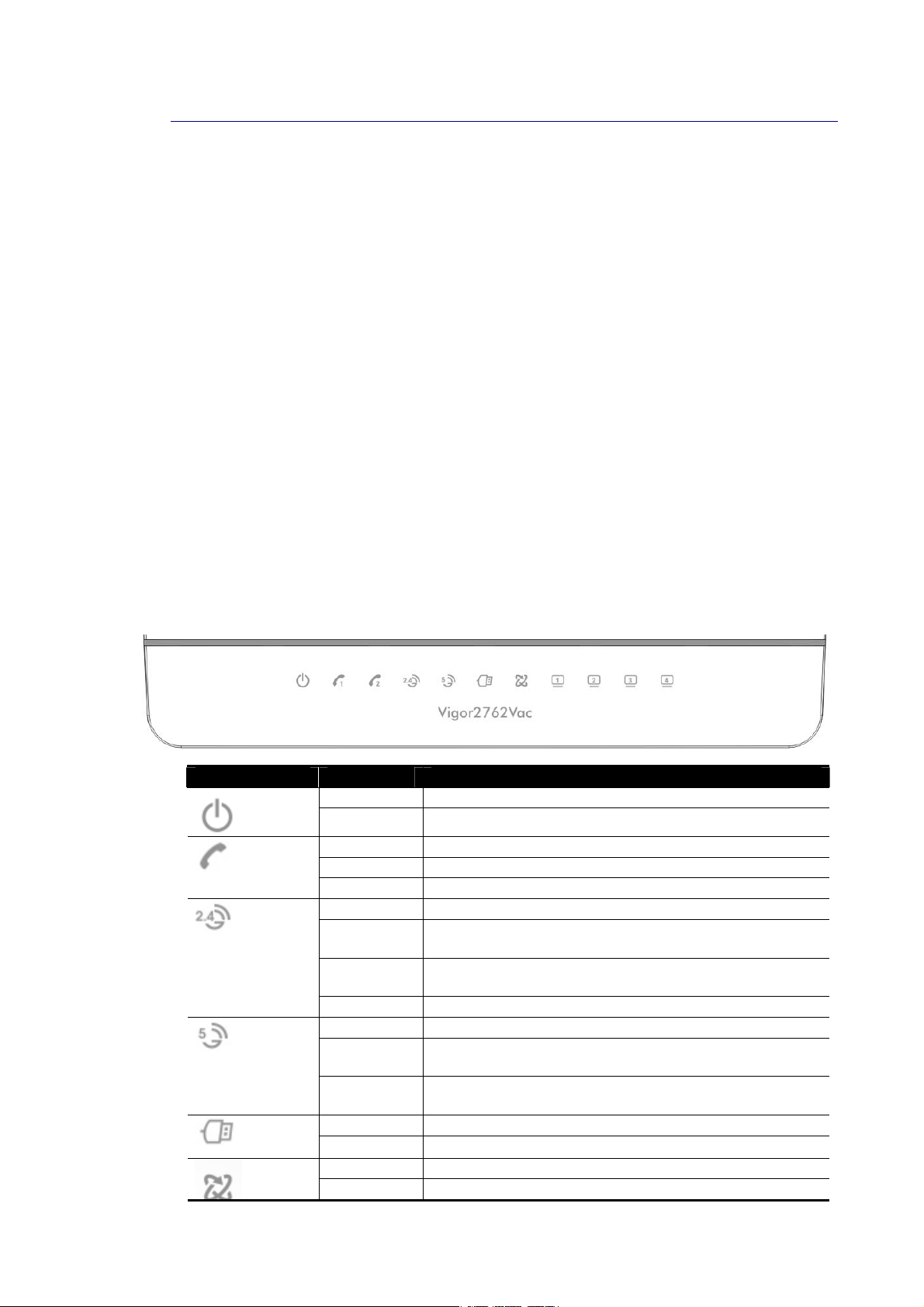
II--11--11 IInnddiiccaattoorrss aanndd CCoonnnneeccttoorrss
Before you use the Vigor router, please get acquainted with the LED indicators and
connectors first.
LED Status Explanation
Blinking The router is powered on and running normally.
(Activity)
(for “V” model)
(Wireless LAN
On/Off/WPS)
(Wireless LAN
On/Off/WPS)
(USB)
Off The router is powered off.
On The phone connected to this port is off-hook.
Off The phone connected to this port is on-hook.
Blinking A phone call comes.
On (Green) The wireless access point is ready.
Blinking
(Green)
Blinking
(Orange)
Off The wireless access point is turned off.
On (Green) The wireless access point is ready.
Blinking
(Green)
Blinking
(Orange)
On A USB device is connected and active.
The data is transmitting via wireless connection based
on the rate of 2.4Ghz.
Blinks with one second cycle for two minutes. The WPS
function is active.
The data is transmitting via wireless connection based
on the rate of 5Ghz.
Blinks with one second cycle for two minutes. The WPS
function is active.
Blinking The data is transmitting.
On The DSL port is connected.
Blinking The router is ready.
Vigor2762 Series User’s Guide
3
Page 16

~
(LAN1/2/3/4)
(Slowly)
Blinking
(Quickly)
On The LAN port is connected.
Blinking The data is transmitting.
Off The LAN port is disconnected.
The router is trying to connect to Internet.
4
Vigor2762 Series User’s Guide
Page 17

VViiggoorr22776622
VViiggoorr22776622nn // VViiggoorr22776622aacc
VViiggoorr22776622VVaacc
Interface Description
Factory Reset
WLAN
ON/OFF/WPS
USB1~USB2 Connector for a USB device (for 3G/4G USB Modem or printer).
GigaLAN1~LAN4 Connectors for local networked devices.
DSL
Phone2/Phone1
(for “V” model)
I / O
Restore the default settings. Usage: Turn on the router (ACT LED is
blinking). Press the hole and keep for more than 5 seconds. When you
see the ACT LED begins to blink rapidly than usual, release the button.
Then the router will restart with the factory default configuration.
WLAN On - Press the button and release it within 2 seconds. When the
wireless function is ready, the green LED will be on.
WLAN Off - Press the button and release it within 2 seconds to turn off
the WLAN function. When the wireless function is not ready, the LED will
be off.
WPS - When WPS function is enabled by web user interface, press this
button for mor e t h a n 2 seconds to wait for cl ient’s device m aki ng
network connection through WPS.
Connector for accessing the Internet.
Connector of analog phone for VoIP communication.
Power Switch.
PWR Connector for a power adapter.
Vigor2762 Series User’s Guide
5
Page 18
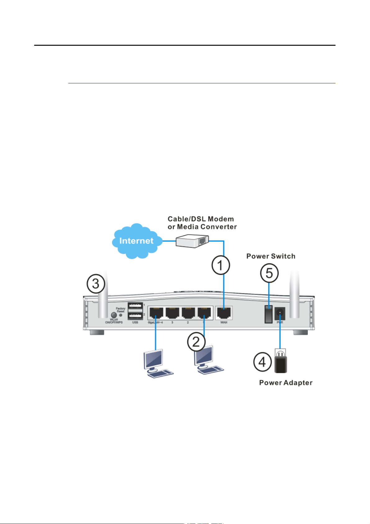
II--22 HHaarrddwwaarree IInnssttaallllaattiioonn
II--22--11 IInnssttaalllliinngg VViiggoorr RRoouutteerr
Before starting to configure the router, you have to connect your devices correctly.
1. Connect the cable Modem/DSL Modem/Media Converter to any WAN port of router with
Ethernet cable (RJ-45).
2. Connect the cable Modem/DSL Modem/Media Converter to any WAN port of router with
Ethernet cable (RJ-45).
3. Connect detachable antennas to the router (for n/ac model only).
4. Connect one end of the power cord to the power port of this device. Connect the other
end to the wall outlet of electricity.
5. Power on the router.
6. Check the ACT and DSL, LAN LEDs to assure network connection.
(For the detailed information of LED status, please refer to section I-1-1 Indicators and
Connectors.)
6
Vigor2762 Series User’s Guide
Page 19
7
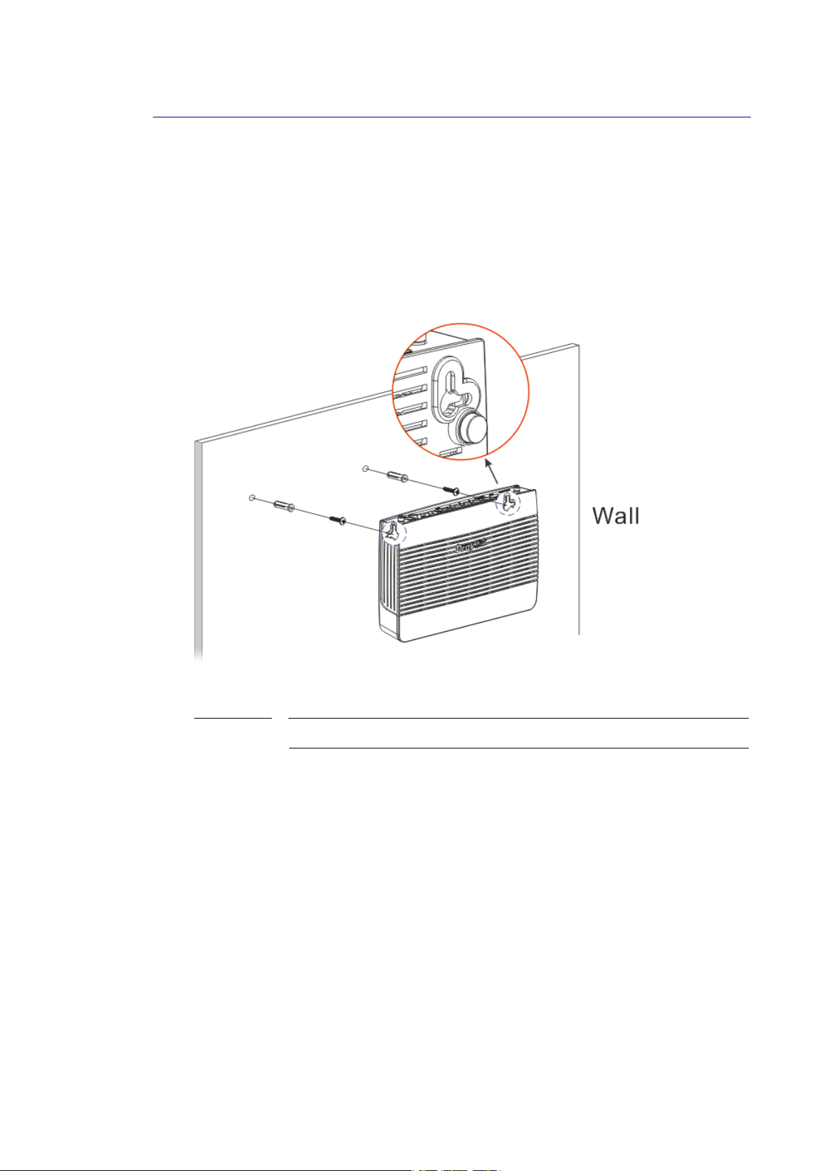
II--22--22 WWaallll--MMoouunntteedd IInnssttaallllaattiioonn
Vigor2762 has keyhole type mounting slots on the underside.
1. A template is provided on the Vigor2762 packaging box to enable you to space the screws
correctly on the wall.
2. Place the template on the wall and drill the holes according to the recommended
instruction.
3. Fit screws into the wall using the appropriate type of wall plug.
Note
4. When you finished about procedure, the router has been mounted on the wall firmly.
The recommended drill diameter shall be 6.5mm (1/4”).
Vigor2762 Series User’s Guide
Page 20
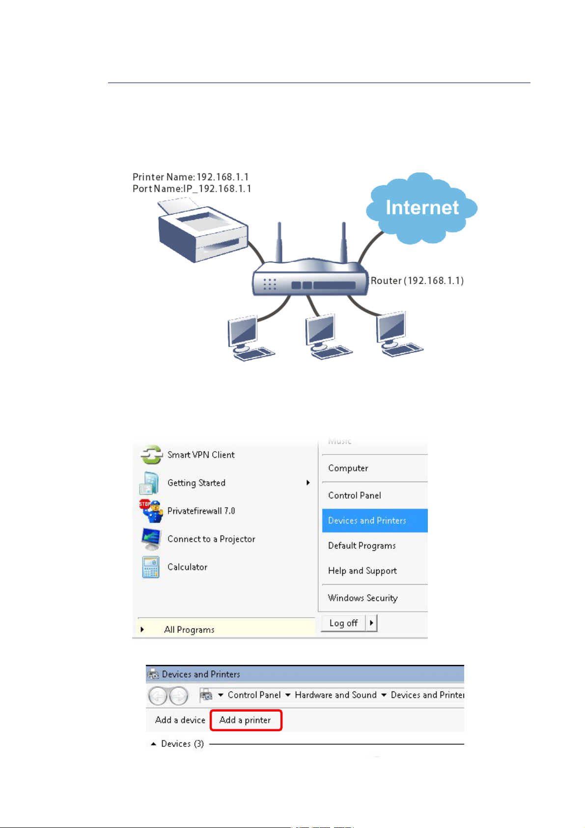
II--22--33 IInnssttaalllliinngg UUSSBB PPrriinntteerr ttoo VViiggoorr RRoouutteerr
You can install a printer onto the router for sharing printing. All the PCs connected this router
can print documents via the router. The example provided here is made ba sed on Windows 7.
For other Windows system, please visit www.DrayTek.com.
Before using it, please follow the steps below to configure settings for connected computers
(or wireless clients).
1. Connect the printer with the router through USB/parallel port.
2. Open All Programs>>Getting Started>>Devices and Printers.
3. Click Add a printer.
8
Vigor2762 Series User’s Guide
Page 21
9
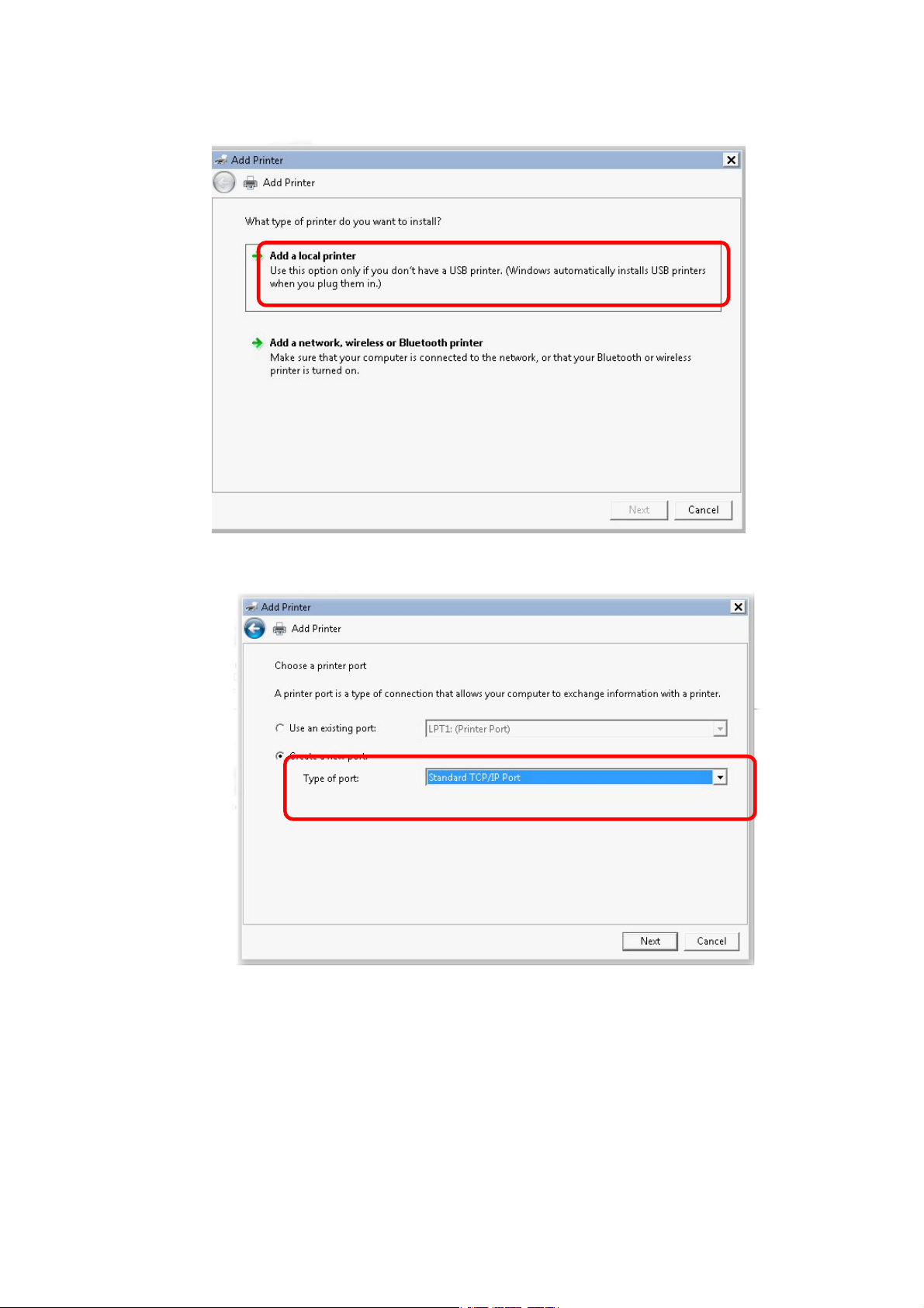
4. A dialog will appear. Click Add a local printer and click Next.
5. In this dialog, choose Create a new port. In the field of Type of port, use the drop down
list to select Standard TCP/IP Port. Then, click Next.
Vigor2762 Series User’s Guide
Page 22
0
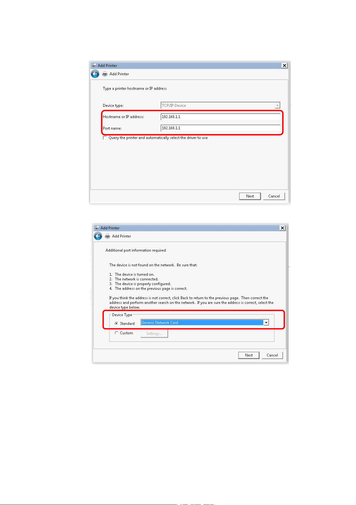
6. In the following dialog, type 192.168.1.1 (router’s LAN IP) in the field of Hostname or
IP Address and type 192.168.1.1 as the Port name. Then, click Next.
7. Click Standard and choose Generic Network Card.
1
Vigor2762 Series User’s Guide
Page 23
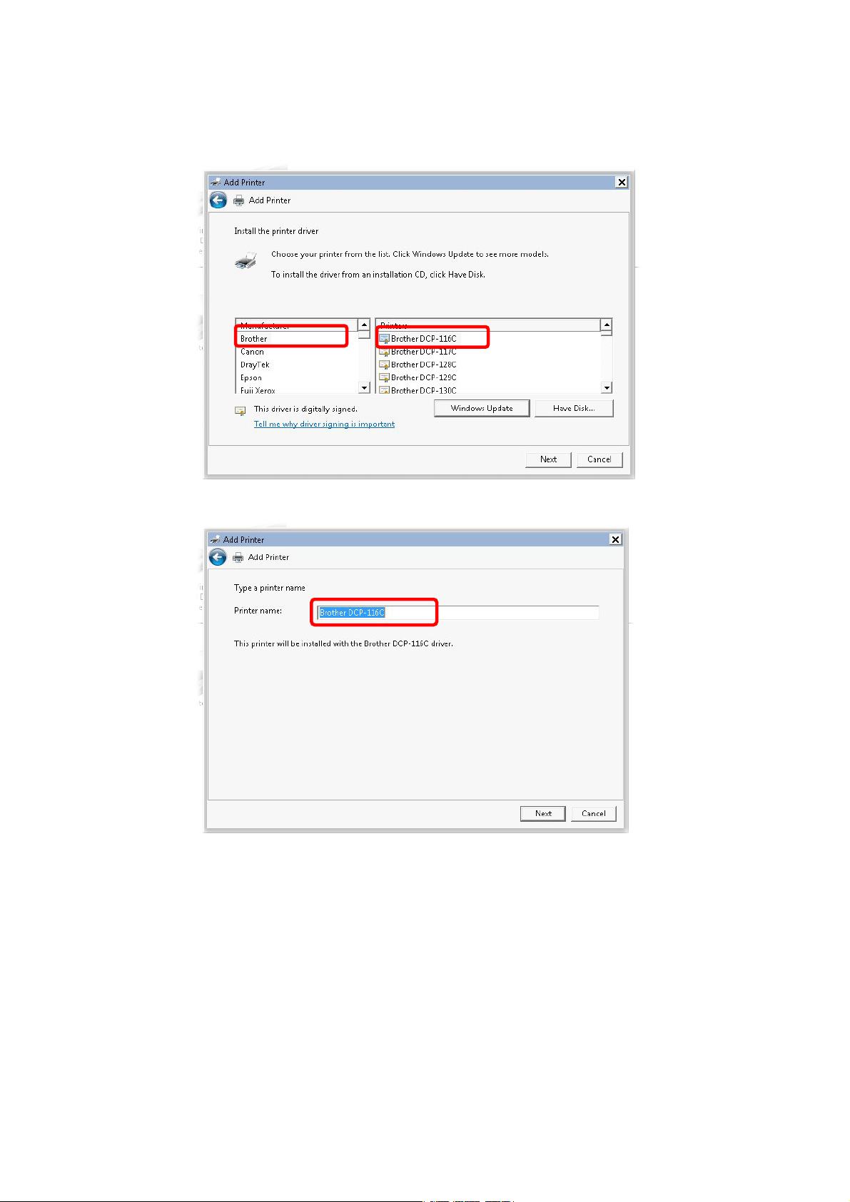
8. Now, your system will ask you to choose right name of the printer that you installed onto
the router. Such step can make correct driver loaded onto your PC. When you finish the
selection, click Next.
9. Type a name for the chosen printer. Click Next.
Vigor2762 Series User’s Guide
11
Page 24
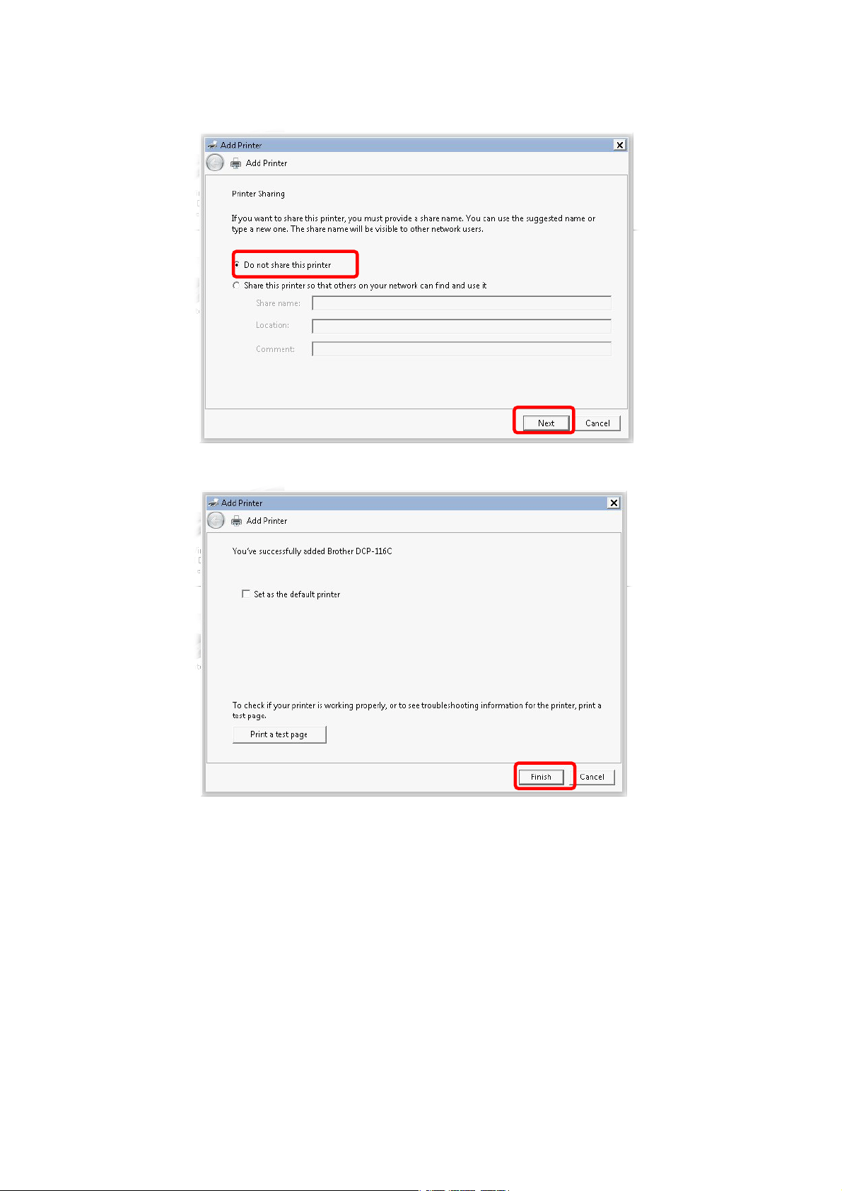
10. Choose Do not share this printer and click Next.
11. Then, in the following dialog, click Finish.
12
Vigor2762 Series User’s Guide
Page 25
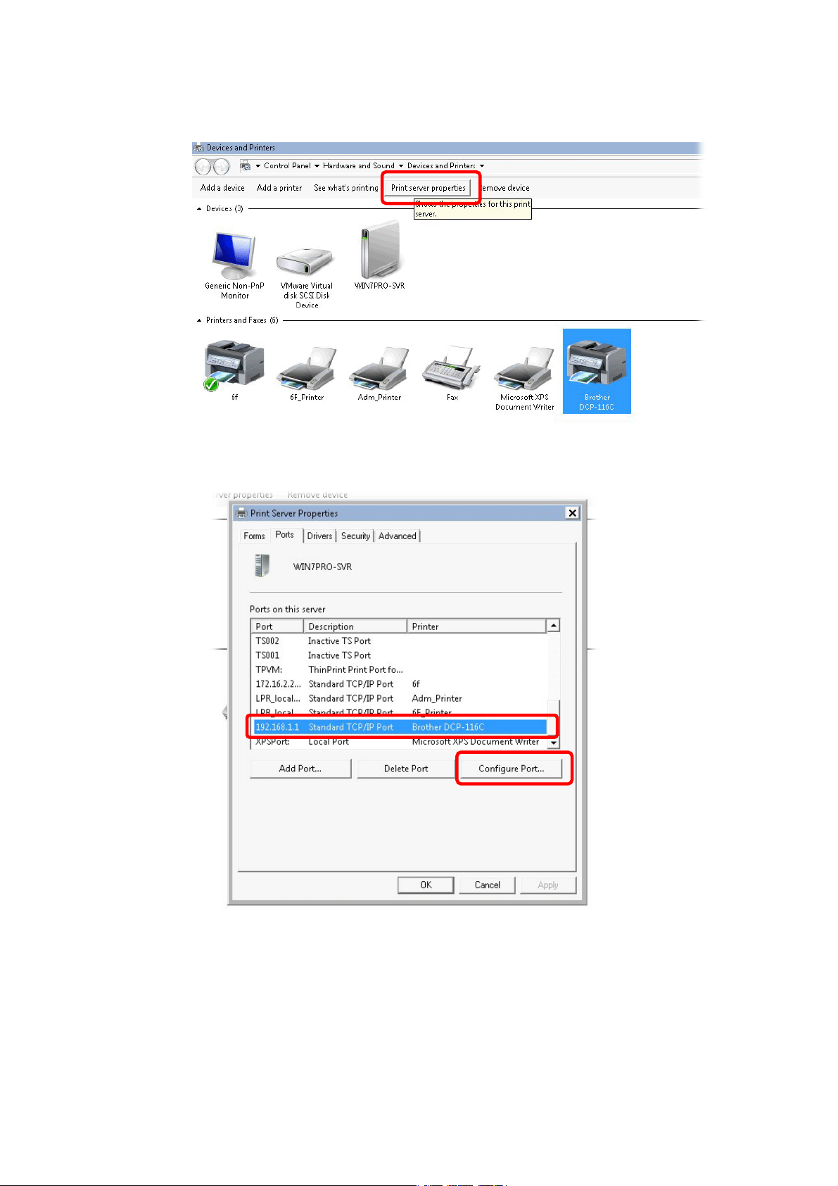
12. The new printer has been added and displayed under Printers and Faxes. Click the new
printer icon and click Printer server properties.
13. Edit the property of the new printer you have added by clicking Configure Port.
Vigor2762 Series User’s Guide
13
Page 26
4
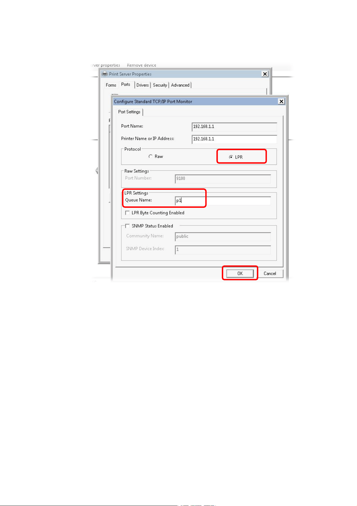
14. Select "LPR" on Protocol, type p1 (number 1) as Queue Name. Then click OK. Next
please refer to the red rectangle for choosing the correct protocol and LPR name.
1
Vigor2762 Series User’s Guide
Page 27

The printer can be used for printing now. Most of the printers with different manufacturers
are compatible with vigor router.
Info
Note 1: Some printers with the fax/scanning or other additional functions are not
supported. If
you do not know whether your printer is supported or not,
please visit www.draytek.com to find out the printer list. Open Support
>FAQ/Application Notes; find out the link of USB>>Printer Server and click
it.
Then, click the What types of printers are compatible with Vigor router?
link.
Note 2: Vigor router supports printing request from computers via LAN ports
but not WAN port.
Vigor2762 Series User’s Guide
15
Page 28
II--33 AAcccceessssiinngg WWeebb PPaaggee
1. Make sure your PC connects to the router correctly.
You may either simply set up your computer to get IP dynamically from the router or set
up the IP address of the computer to be the same subnet as the default IP address of
Vigor router 192.168.1.1. For the detailed information, please refer to the later
section - Trouble Shooting of the guide.
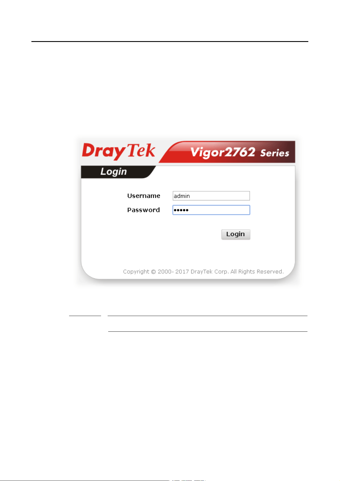
2. Open a web browser on your PC and type http://192.168.1.1. The following window
will be open to ask for username and password.
3. Please type “admin/admin” as the Username/Password and click Login.
Info
If you fail to access to the web configuration, please go to “Trouble Shooting” for
detecting and solving your problem.
16
Vigor2762 Series User’s Guide
Page 29

7
4. Now, the Main Screen will appear.
Info
The home page will be different slightly in accordance with the type of the
router you have.
5. The web page can be logged out according to the chosen condition. The default setting
is Auto Logout, which means the web configuration system will logout after 5 minutes
without any operation. Change the setting for your necessity.
Vigor2762 Series User’s Guide
1
Page 30
II--44 CChhaannggiinngg PPaasssswwoorrdd
Please change the password for the original security of the router.
1. Open a web browser on your PC and type http://192.168.1.1. A pop-up window will
open to ask for username and password.
2. Please type “admin/admin” as Username/Password for acce ssing into the web user
interface with admin mode.
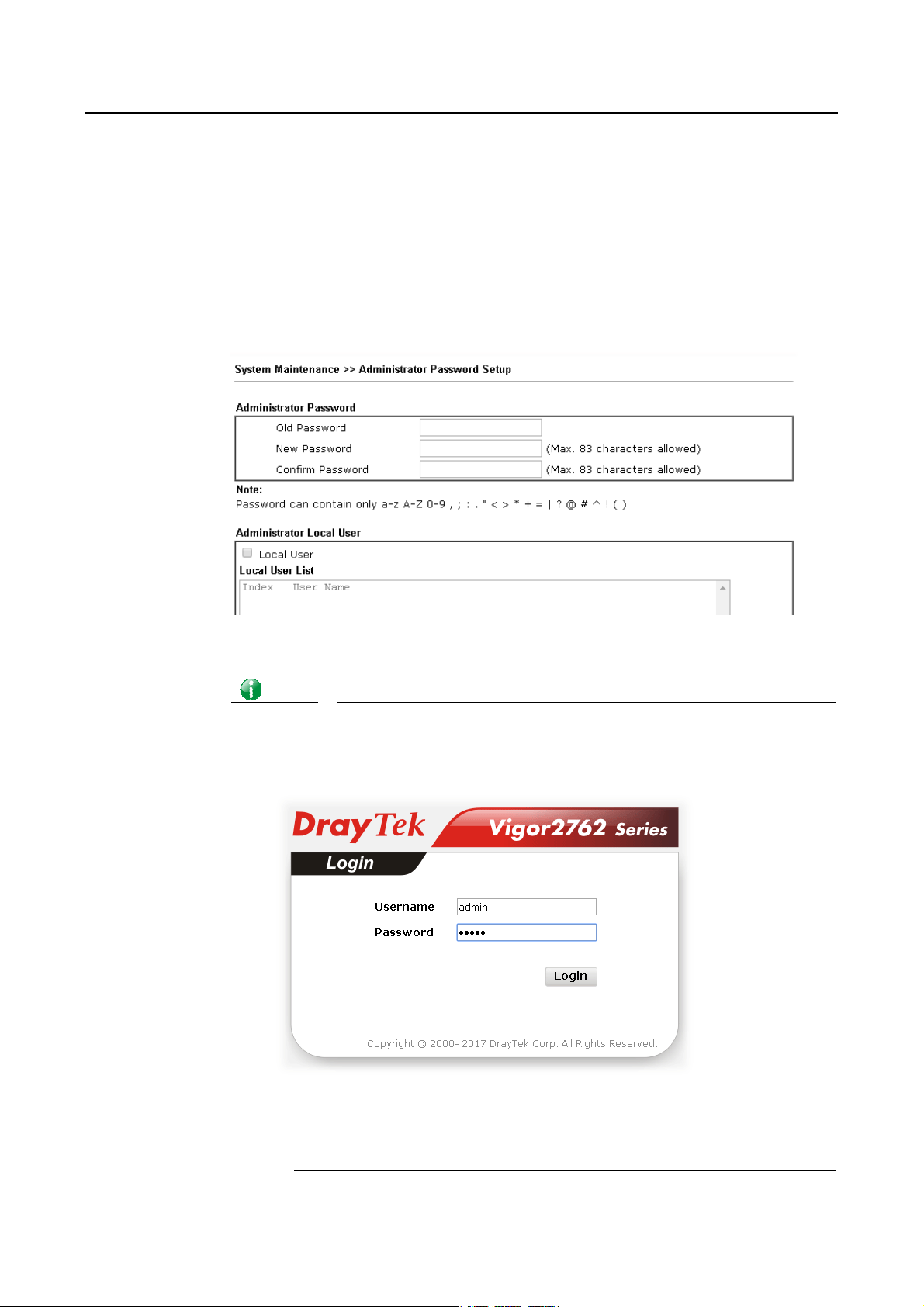
3. Go to System Maintenance page and choose Administrator Password.
4. Enter the login password (the default is “admin”) on the field of Old Password. Type
New Password and Confirm Password. Then click OK to continue.
Info
5. Now, the password has been changed. Next time, use the new password to access the
Web user interface for this router.
The maximum length of the password you can set is 23 characters.
Info
18
Even the password is changed, the Username for logging onto the web user interface
is still “admin”.
Vigor2762 Series User’s Guide
Page 31

9
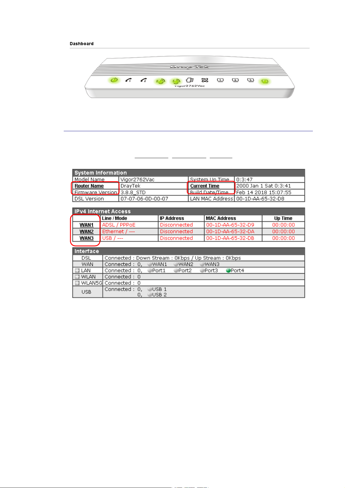
II--55 DDaasshhbbooaarrdd
Dashboard shows the connection status including System Information, IPv4 In ternet Access,
IPv6 Internet Access, Interface (physical connection), Security and Quick Access.
Click Dashboard from the main menu on the left side of the main page.
A web page with default selections will be displayed on the screen. Refer to the following
figure:
II--55--11 VViirrttuuaall PPaanneell
On the top of the Dashboard, a virtual panel (simulating the physical panel of the router)
displays the physical interface connection. It will be refreshed every five seconds. When you
move and click the mouse cursor on LEDs (except ACT), USB ports, LAN, or WAN, related web
setting page will be open for you to configure if required.
Vigor2762 Series User’s Guide
1
Page 32
0
For detailed information about the LED display, refer to I-1-1 LED Indicators and
Connectors.
II--55--22 NNaammee wwiitthh aa LLiinnkk
A name with a link (e.g., Router Name, Current Time, WAN1~4 and etc.) below means you can
click it to open the configuration page for modification.
2
Vigor2762 Series User’s Guide
Page 33

II--55--33 QQuuiicckk AAcccceessss ffoorr CCoommmmoonn UUsseedd MMeennuu
All the menu items can be accessed and arranged orderly on the left side of the main page for
your request. However, some important and common used menu items which can be
accessed in a quick way just for convenience.
Look at the right side of the Dashboard. You will find a group of common used functions
grouped under Quick Access.
The function links of System Status, Dynamic DDNS, TR-069, User Management, IM/P2P Block,
Schedule, Syslog/Mail Alert, LDAP, RADIUS, Firewall Object Setting and Data Flow Monitor are
displayed here. Move your mouse cursor on any one of the links and click on it. The
corresponding setting page will be open immediately.
In addition, quick access for VPN security settings such as Remote Dial-in User and LAN to
LAN are located on the bottom of this page. Scroll down the page to find them and use them
if required.
Note that there is a plus (
VPN connection(s) used presently.
) icon located on the left side of VPN/LAN. Click it to review the
Vigor2762 Series User’s Guide
21
Page 34

Host connected physically to the router via LAN port(s) will be displayed with green circles in
the field of Connected.
All of the hosts (including wireless clients) displayed with Host ID, IP Address and MAC address
indicates that the traffic would be transmitted through LAN port(s) and then the WAN port.
The purpose is to perform the traffic monitor of the host(s).
II--55--44 GGUUII MMaapp
All the functions the router supports are listed with table clearly in this page. Users can click
the function link to access into the setting page of the function for detailed configuration.
Click the icon on the top of the main screen to display all the functions.
22
Vigor2762 Series User’s Guide
Page 35

II--55--55 WWeebb CCoonnssoollee
It is not necessary to use the telnet command via DOS prompt. The changes made by using
web console have the same effects as modified through web user interface. The
functions/settings modified under Web Console also can be reviewed on the web user
interface.
Click the Web Console icon on the top of the main screen to open the following screen.
Vigor2762 Series User’s Guide
23
Page 36
4
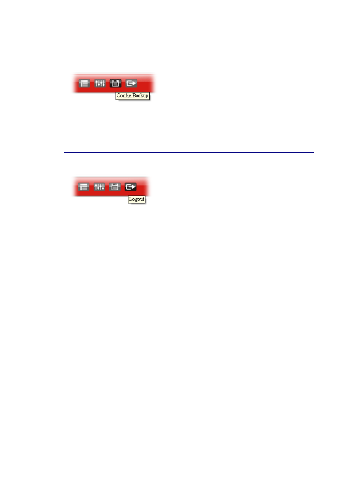
II--55--66 CCoonnffiigg BBaacckkuupp
There is one way to store current used settings quickly by clicking the Config Backup icon. It
allows you to backup current settings as a file. Such configuration file can be restored by
using System Maintenance>>Configuration Backup.
Simply click the icon on the top of the main screen to store the setting.
II--55--77 LLooggoouutt
Click this icon to exit the web user interface.
2
Vigor2762 Series User’s Guide
Page 37
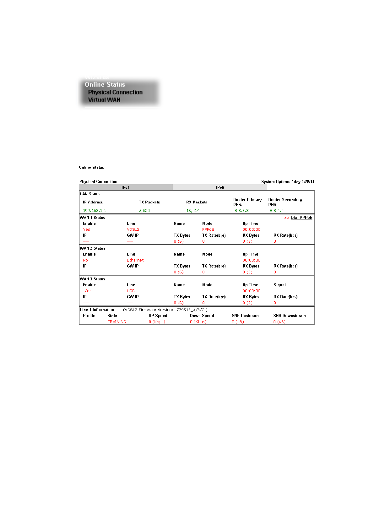
II--55--88 OOnnlliinnee SSttaattuuss
II--55--88--11 PPhhyyssiiccaall CCoonnnneeccttiioonn
Such page displays the physical connection status such as LAN connection status, WAN
connection status, ADSL information, and so on.
Physical Connection for IPv4 Protocol
Vigor2762 Series User’s Guide
25
Page 38

Physical Connection for IPv6 Protocol
Detailed explanation (for IPv4) is shown below:
Item Description
LAN Status Primary DNS-Displays the primary DNS server address for
WAN interface.
Secondary DNS -Displays the secondary DNS server address
for WAN interface.
IP Address-Displays the IP address of the LAN interface.
TX Packets-Displays the total transmitted packets at the
LAN interface.
RX Packets-Displays the total received packets at the LAN
interface.
WAN1/WAN2/WAN3
/WAN4 Status
Enable – Yes in red means such interface is available but
not enabled. Yes in green means such interface is enabled.
Line – Displays the physical connection (VDSL, ADSL,
Ethernet, or USB) of this interface.
Name – Display the name of the router.
Mode - Displays the type of WAN connection (e.g., PPPoE).
Up Time - Displays the total uptime of the interface.
IP - Displays the IP address of the WAN interface.
GW IP - Displays the IP address of the default gateway.
TX Packets - Displays the total transmitted packets at the
WAN interface.
TX Rate - Displays the speed of transmitted octets at the
WAN interface.
RX Packets - Displays the total number of received packets
at the WAN interface.
RX Rate - Displays the speed of received octets at the WAN
26
Vigor2762 Series User’s Guide
Page 39

7
Item Description
interface.
Detailed explanation (for IPv6) is shown below:
Item Description
LAN Status IP Address- Displays the IPv6 address of the LAN interface..
TX Packets-Displays the total transmitted packets at the LAN
interface.
RX Packets-Displays the total received packets at the LAN
interface.
TX Bytes - Displays the speed of transmitted octets at the
LAN interface.
RX Bytes - Displays the speed of received octets at the LAN
interface.
WAN IPv6 Status Enable – No in red means such interface is available but not
enabled. Yes in green means such inte rface is enabled. No in
red means such interface is not available.
Mode - Displays the type of WAN connection (e.g., TSPC).
Up Time - Displays the total uptime of the interface.
IP - Displays the IP address of the WAN interface.
Gateway IP - Displays the IP address of the default gateway.
Info
The words in green mean that the WAN connection of that interface is ready for
accessing Internet; the words in red mean that the WAN connection of that interf ace
is not ready for accessing Internet.
II--55--88--22 VViirrttuuaall WWAANN
Such page displays the virtual WAN connection information.
Virtual WAN are used by TR-069 management, VoIP service and so on.
The field of Application will list i-9the purpose of such WAN connection.
Vigor2762 Series User’s Guide
2
Page 40

II--66 QQuuiicckk SSttaarrtt WWiizzaarrdd
Quick Start Wizard can help you to deploy and use the router easily and quickly. Click
Wizards>>Quick Start Wizard. The first screen of Quick Start Wizard is entering login
password. After typing the password, please click Next.
On the next page as shown below, please select the WAN interface (WAN 1 to WAN3) that you
use. If DSL interface is used, please choose WAN1; if Ethernet interface is used, please choose
WAN2; if 3G/4G USB modem is used, please choose WAN3. For WAN2, ch oose Auto
negotiation as the physical type for your router.
WAN1~ WAN3 will bring up different configuration page. Refer to the following sections for
detailed information.
28
Vigor2762 Series User’s Guide
Page 41

9
II--66--11 FFoorr WWAANN11 ((AADDSSLL))
WAN1 is specified for ADSL or VDSL2 connection.
Available settings are explained as follows:
Item Description
Display Name Type a name to identify such WAN.
VLAN Tag insertion
(VDSL2)/(ADSL)
Please select the appropriate Internet access type according to the information from your
ISP. Click Next.
PPPPPPooEE//PPPPPPooAA
PPPoE stands for Point-to-Point Protocol over Ethernet. It relies on two widely accepted
standards: PPP and Ethernet. It connects users through an Ethernet to the Internet with a
common broadband medium, such as a single DSL line, wireless device or cable modem. All
the users over the Ethernet can share a common connection.
The settings configured in this field are available for WAN1
and WAN2.
Enable – Enable the function of VLAN with tag.
The router will add specific VLAN number to all packets on
the WAN while sending them out.
Please type the tag value and specify the priority for the
packets sending by WAN1.
Disable – Disable the function of VLAN with tag.
Tag value – Type the value as the VLAN ID number. The range
is from 0 to 4095.
Priority – Type the packet priority number for such VLAN.
The range is from 0 to 7.
PPPoE is used for most of DSL modem users. All local users can share one PPPoE connection
for accessing the Internet. Your service provider will provide you information a bout user
name, password, and authentication mode.
1. Choose WAN1 as WAN Interface and click the Next button; you will get the following
page. Choose PPPoE XXXX or PPPoA XXXXX as the protocol.
Vigor2762 Series User’s Guide
2
Page 42

0
Available settings are explained as follows:
Item Description
Protocol /
Choose PPPoE/PPPoA for WAN1 interface.
Encapsulation
VPI Type in the value provided by ISP.
Auto detect – Click this button to have the VPI and VCI to be
detected by the system automatically
VCI Type in the value provided by ISP.
Fixed IP Click Yes to enable Fixed IP feature.
IP Address Type the IP address if Fixed IP is enabled.
Primary DNS Type in the primary IP address for the router.
Secondary DNS Type in secondary IP address for necessity in the future.
Back Click it to return to previous setting page.
Next Click it to get into the next setting page.
Cancel Click it to give up the quick start wizard.
2. After finished the above settings, simply click Next.
3
Vigor2762 Series User’s Guide
Page 43

Available settings are explained as follows:
Item Description
Service Name
Enter the description of the specific network service.
(Optional)
User Name Type in the valid user name (maximum 63 characters)
provided by the ISP in this field.
Password Type a valid password provided by the ISP.
Confirm Password Retype the password.
Back Click it to return to previous setting page.
Next Click it to get into the next setting page.
Cancel Click it to give up the quick start wizard.
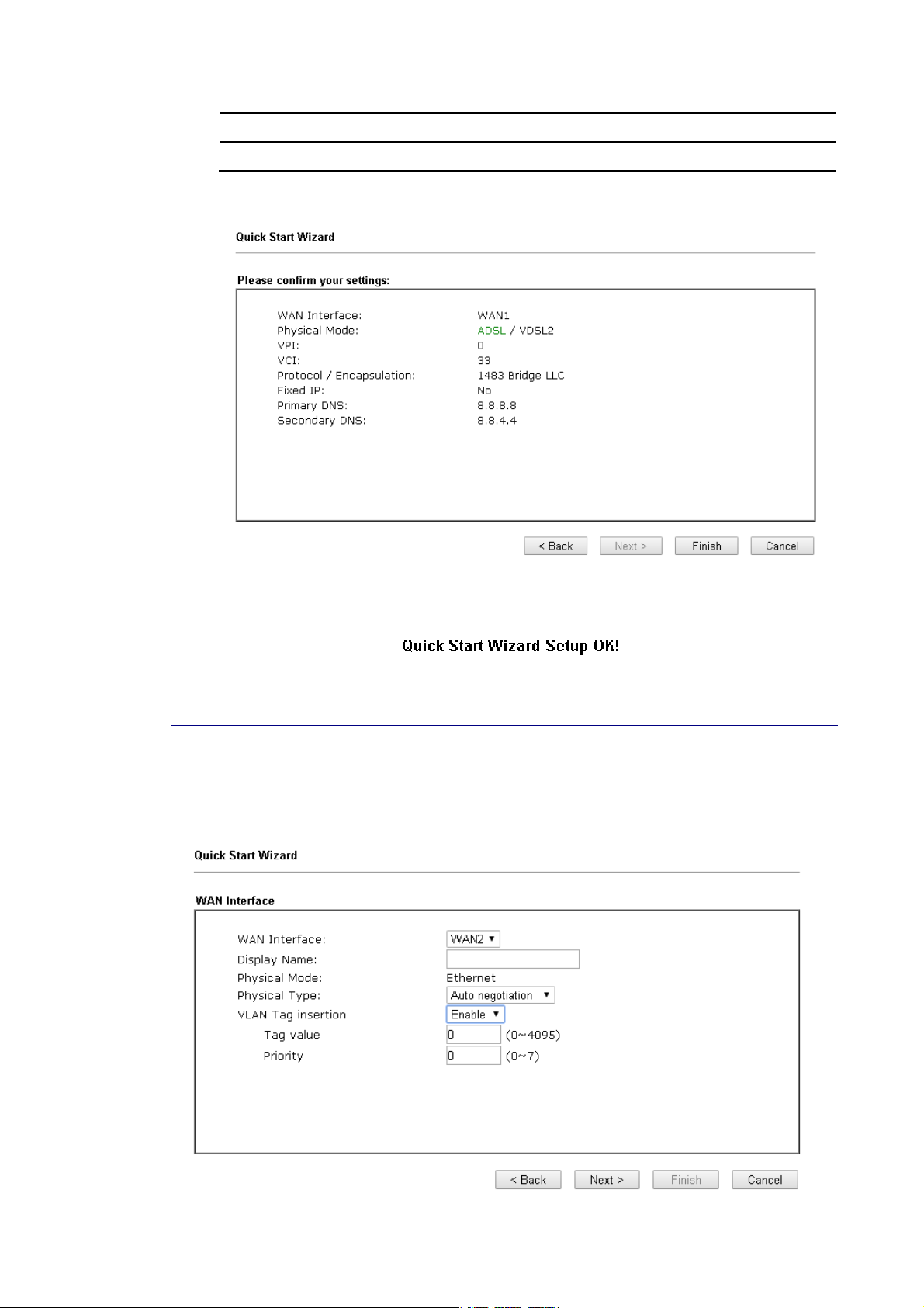
3. Please manually enter the Username/Password provided by your ISP. Then click Next for
viewing summary of such connection.
4. Click Finish. A page of Quick Start Wizard Setup OK!!! will appear. Then, the system
status of this protocol will be shown.
Vigor2762 Series User’s Guide
31
Page 44

5. Now, you can enjoy surfing on the Internet.
MMPPooAA
1. Choose WAN1 as WAN Interface and click the Next button; you will get the following
page.
Available settings are explained as follows:
Item Description
Protocol There are two modes offered for you to choose for WAN1
interface. Choose MPoA as the protocol.
For ADSL Only Such field is provided for ADSL only. You have to choose
encapsulation and type the values for VPI and VCI. Or, click
Auto detect to find out the best values.
Fixed IP Click Yes to enable Fixed IP feature.
IP Address Type the IP address if Fixed IP is enabled.
Subnet Mask Type the subnet mask.
Default Gateway Type the IP address as the default gateway.
Primary DNS Type in the primary IP address for the router.
Secondary DNS Type in secondary IP address for necessity in the future.
Back Click it to return to previous setting page.
32
Vigor2762 Series User’s Guide
Page 45
Next Click it to get into the next setting page.
Cancel Click it to give up the quick start wizard.
2. Please type in the IP address/mask/gateway information originally provided by your ISP.
Then click Next for viewing summary of such connection.
3. Click Finish. A page of Quick Start Wizard Setup OK!!! will appear. Then, the system
status of this protocol will be shown.
4. Now, you can enjoy surfing on the Internet.
II--66--22 FFoorr WWAANN22 ((EEtthheerrnneett))
WAN2 is dedicated to physical mode in Ethernet. Please select the appropriate Internet
access type according to the information from your ISP. For example, you should select PPPoE
mode if the ISP provides you PPPoE interface.
Vigor2762 Series User’s Guide
33
Page 46
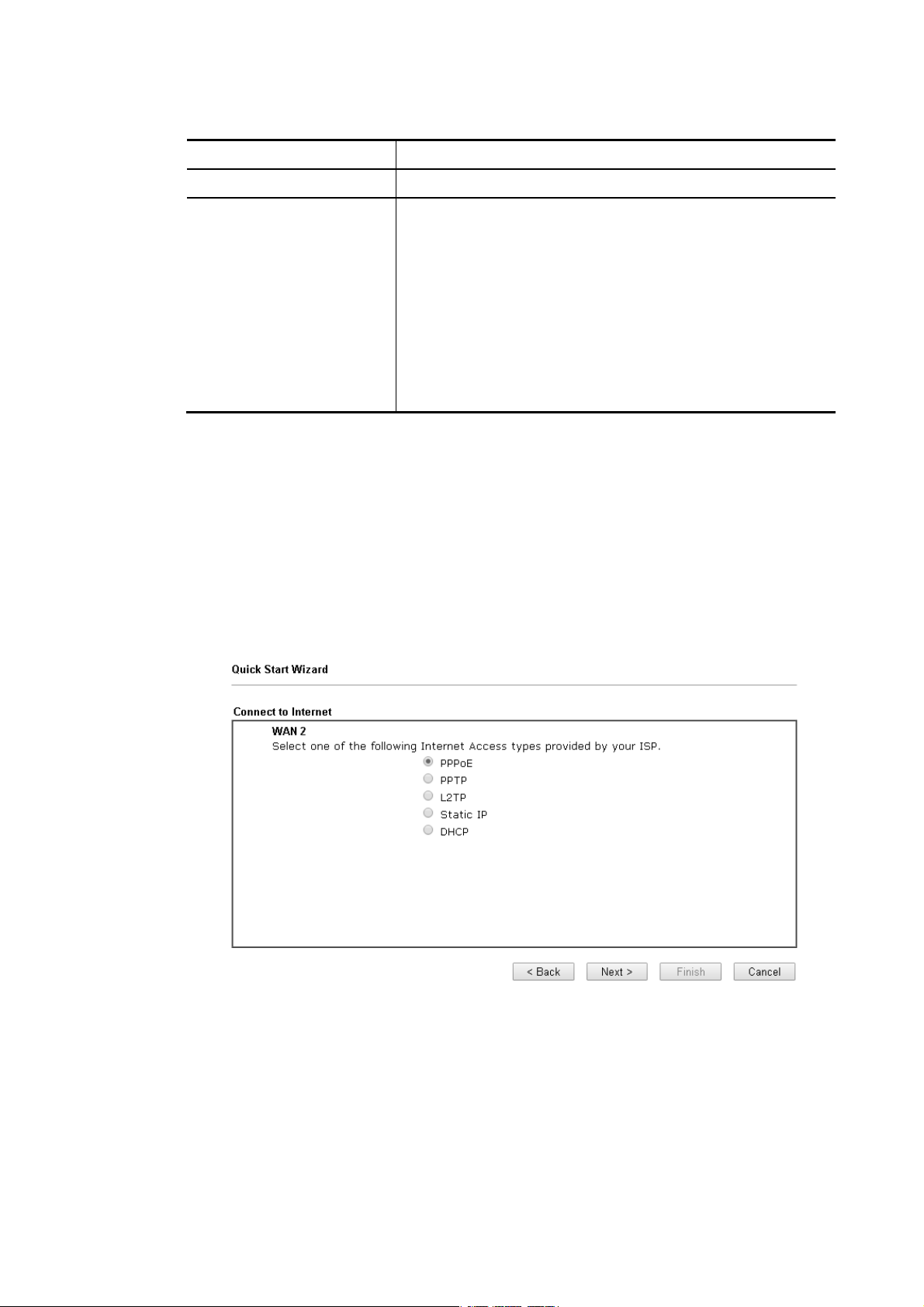
4
Available settings are explained as follows:
Item Description
Display Name Type a name for the router.
VLAN Tag insertion Enable – Enable the function of VLAN with tag.
The router will add specific VLAN number to all packets on
the WAN while sending them out.
Please type the tag value and specify the priority for the
packets sending by WAN2.
Disable – Disable the function of VLAN with tag.
Tag value – Type the value as the VLAN ID number. The range
is form 0 to 4095.
Priority – Type the packet priority number for such VLAN.
The range is from 0 to 7.
PPPPPPooEE
PPPoE stands for Point-to-Point Protocol over Ethernet. It relies on two widely accepted
standards: PPP and Ethernet. It connects users through an Ethernet to the Internet with a
common broadband medium, such as a single DSL line, wireless device or cable modem. All
the users over the Ethernet can share a common connection.
PPPoE is used for most of DSL modem users. All local users can share one PPPoE connection
for accessing the Internet. Your service provider will provide you information a bout user
name, password, and authentication mode.
1. Choose WAN2 as the WAN Interface and click the Next button. The following page will
be open for you to specify Internet Access Type.
3
Vigor2762 Series User’s Guide
Page 47
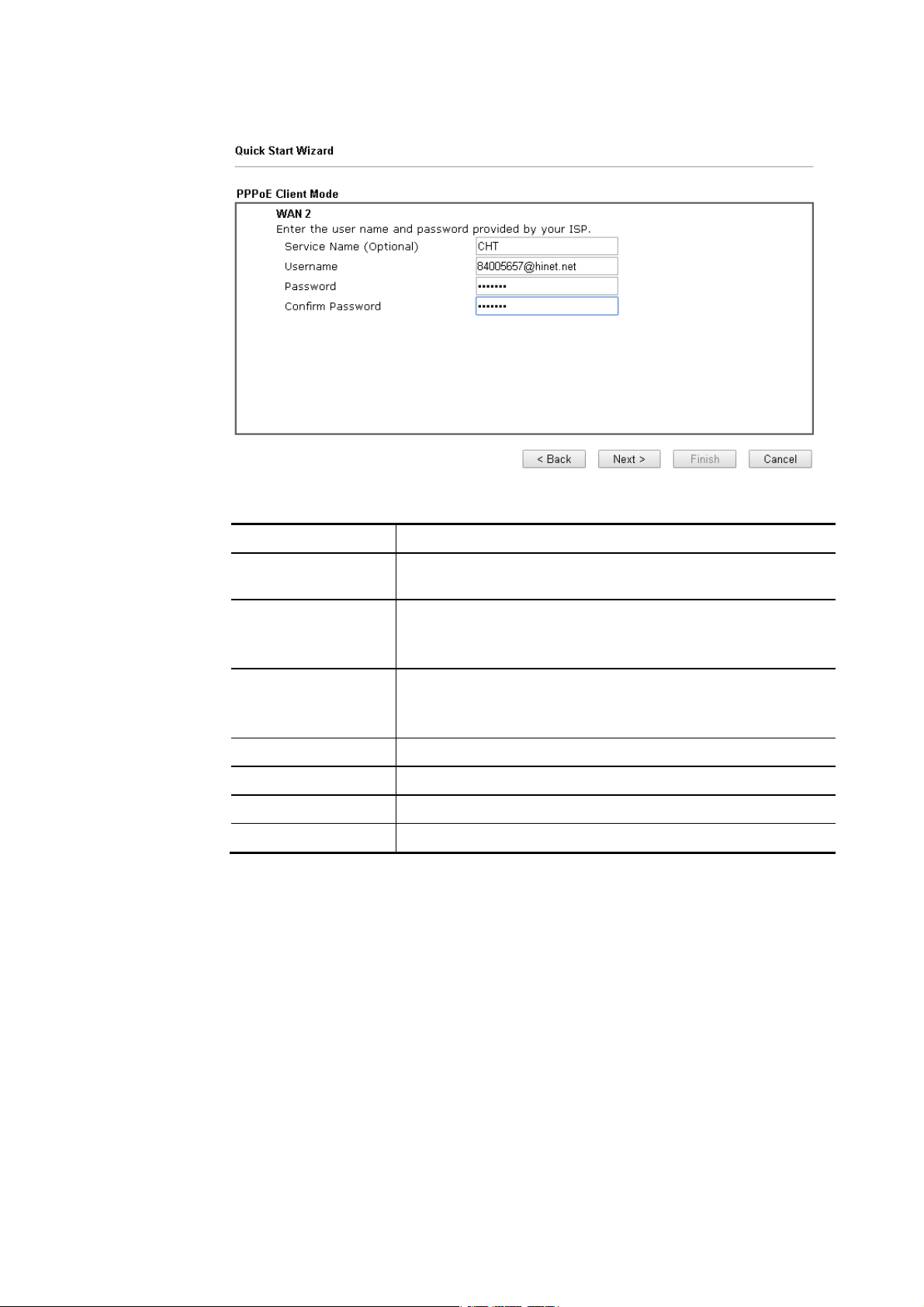
2. Click PPPoE as the Internet Access Type. Then click Next to continue.
Available settings are explained as follows:
Item Description
Service Name
Enter the description of the specific network service.
(Optional)
Username Assign a specific valid user name pr ovided by the ISP.
Note: The maximum length of the user name you can set is
63 characters.
Password Assign a valid password provided by the ISP.
Note: The maximum length of the password you can set is 62
characters.
Confirm Password Retype the password.
Back Click it to return to previous setting page.
Next Click it to get into the next setting page.
Cancel Click it to give up the quick start wizard.
Vigor2762 Series User’s Guide
35
Page 48

3. Please manually enter the Username/Password provided by your ISP. Click Next for
viewing summary of such connection.
4. Click Finish. A page of Quick Start Wizard Setup OK!!! will appear. Then, the system
status of this protocol will be shown.
5. Now, you can enjoy surfing on the Internet.
36
Vigor2762 Series User’s Guide
Page 49

7
PPPPTTPP//LL22TTPP
1. Choose WAN2 as the WAN Interface and click the Next button. The following page will
2. Click PPTP/L2TP as the Internet Access Type. Then click Next to continue.
be open for you to specify Internet Access Type.
Available settings are explained as follows:
Item Description
Username Assign a specific valid user name provided by the ISP.
The maximum length of the user name you can set is 63
characters.
Password Assign a valid password provided by the ISP.
The maximum length of the password you can set is 62
characters.
Confirm Password Retype the password.
Vigor2762 Series User’s Guide
3
Page 50
WAN IP Configuration Obtain an IP address automatically – the router will get an
IP address automatically from DHCP server.
Specify an IP address – you have to type relational settings
manually.
IP Address - Type the IP address.
Subnet Mask –Type the subnet mask.
Gateway – Type the IP address of the gateway.
Primary DNS –Type in the primary IP address for the
router.
Second DNS –Type in secondary IP address for necessity
in the future.
PPTP Server / L2TP
Server
Back Click it to return to previous setting page.
Next Click it to get into the next setting page.
Cancel Click it to give up the quick start wizard.
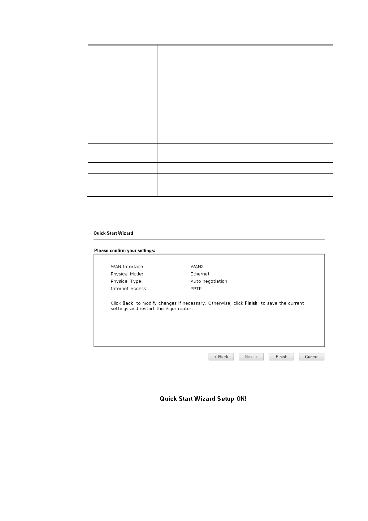
3. Please type in the IP address/mask/gateway information originally provided by your ISP.
Then click Next for viewing summary of such connection.
Type the IP address of the server.
4. Click Finish. A page of Quick Start Wizard Setup OK!!! will appear. Then, the system
status of this protocol will be shown.
5. Now, you can enjoy surfing on the Internet.
38
Vigor2762 Series User’s Guide
Page 51

9
SSttaattiicc IIPP
1. Choose WAN2 as the WAN Interface and click the Next button. The following page will
be open for you to specify Internet Access Type.
2. Click Static IP as the Internet Access type. Simply click Next to continue.
Available settings are explained as follows:
Item Description
WAN IP Type the IP address.
Subnet Mask Type the subnet mask.
Gateway Type the IP address of gateway.
Primary DNS Type in the primary IP address for the router.
Secondary DNS Type in secondary IP address for necessity in the future.
Back Click it to return to previous setting page.
Vigor2762 Series User’s Guide
3
Page 52

0
Next Click it to get into the next setting page.
Cancel Click it to give up the quick start wizard.
3. Please type in the IP address information originally provided by your ISP. Then click Next
for next step.
4. Click Finish. A page of Quick Start Wizard Setup OK!!! will appear. Then, the system
status of this protocol will be shown.
5. Now, you can enjoy surfing on the Internet.
4
Vigor2762 Series User’s Guide
Page 53

DDHHCCPP
1. Choose WAN2 as WAN Interface and click the Next button. The following page will be
open for you to specify Internet Access Type.
2. Click DHCP as the Internet Access type. Simply click Next to continue.
Available settings are explained as follows:
Item Description
Host Name Type the name of the host.
Note: The maximum length of the host name you can set is
39 characters.
MAC Some Cable service providers specify a specific MAC address
for access authentication. In such cases you need to enter
the MAC address.
Back Click it to return to previous setting page.
Next Click it to get into the next setting page.
Cancel Click it to give up the quick start wizard.
Vigor2762 Series User’s Guide
41
Page 54
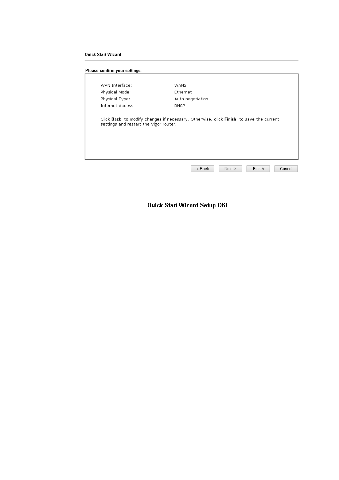
3. After finished the settings above, click Next for viewing summary of such connection.
4. Click Finish. A page of Quick Start Wizard Setup OK!!! will appear. Then, the system
status of this protocol will be shown.
5. Now, you can enjoy surfing on the Internet.
42
Vigor2762 Series User’s Guide
Page 55

II--66--33 FFoorr WWAANN33 ((UUSSBB))
WAN3/WAN4 is dedicated to physical mode in USB.
1. Choose WAN3 as WAN Interface.
2. Then, click Next for getting the following page.
Available settings are explained as follows:
Item Description
Internet Access Choose one of the selections as the protocol of accessing the
internet.
3G/4G USB Modem
(PPP mode)
Vigor2762 Series User’s Guide
SIM Pin code –Type PIN code of the SIM card that will be used
to access Internet. The maximum length of the pin code you
can set is 15 characters.
Modem Initial String – Such value is used to initialize USB
modem. Please use the default value. If you have any
question, please contact to your ISP. The maximum length of
the string you can set is 47 characters.
43
Page 56

4
APN Name – APN means Access Point Name which is provided
and required by some ISPs. Type the name and click Apply.
3. Then, click Next for viewing summary of such connection.
4. Click Finish. A page of Quick Start Wizard Setup OK!!! will appear. Then, the system
status of this protocol will be shown.
5. Now, you can enjoy surfing on the Internet.
4
Vigor2762 Series User’s Guide
Page 57

II--77 SSeerrvviiccee AAccttiivvaattiioonn WWiizzaarrdd
Service Activation Wizard can guide you to activate WCF service (Web Content Filter) with a
quick and easy way. For the Service Activation Wizard is only available for admin
operation, therefore, please type “admin/admin” on Username/Password while Logging
into the web user interface.
Service Activation Wizard is a tool which allows you to use trial version of WCF directly
without accessing into the server (MyVigor) located on http://myvigor.draytek.com. For
using Web Content Filter Profile, please refer to later section Web Content Filter Profile for
detailed information.
Now, follow the steps listed below to activate WCF feature for your router.
Info
1. Open Wizards>>Service Activation Wizard.
Such function is available only for Admin Mode.
2. In the following page, you can activate the Web content filter services and APP
Enforcement service at the same time or individually. When you finish the selection,
check the box of “I have read…” and click Next.
Info
BPjM is web content filter (WCF) for German Speaking users. It is ideal for your
family to provide more Internet security for youngsters.
DT-APPE, developed by DrayTek, offers a mechanism to upgrade APPE
Vigor2762 Series User’s Guide
45
Page 58

signature automatically.
3. Setting confirmation page will be displayed as follows, please click Activate.
Info
The service will be activated and applied as the default rule configured in
Firewall>>General Setup.
4. Now, the web page will display the service that you have activated according to your
selection(s). The valid time for the free trial of these services is one month.
46
Vigor2762 Series User’s Guide
Page 59

7
II--88 RReeggiisstteerriinngg VViiggoorr RRoouutteerr
You have finished the configuration of Quick Start Wizard and you can surf the Internet at any
time. Now it is the time to register your Vigor router to MyVigor website for getting more
service. Please follow the steps below to finish the router registration.
1 Please login the web configuration interface of Vigor router by typing “admin/admin” as
User Name / Password.
2 Click Support Area>>Production Registration from the home page.
3 A Login page will be shown on the screen. Please type the account and password that
you created previously. And click Login.
Info
Vigor2762 Series User’s Guide
If you haven’t an accessing account, please refer to section Creating an
Account for MyVigor to create your own one. Please read the articles on the
Agreement regarding user rights carefully while creating a user account.
4
Page 60

4 The following page will be displayed after you logging in MyVigor. When the following
page appears, please type in Nickname (for the router) and choose the right registration
date from the popup calendar (it appears when you click on the box of Registration
Date). Click Add.
5 When the following page appears, your router information has been added to the
database.
6 After clicking OK, you will see the following page. Your router has been registered to
myvigor website successfully.
48
Vigor2762 Series User’s Guide
Page 61

9
Paarrtt IIII
P
C
C
o
o
n
neeccttiivviittyy
n
n
It means wide area network. Public IP will be used in
WAN.
It means local area network. Private IP will be used in
LAN.
Local Area Network (LAN) is a group of subnets
regulated and ruled by router. The design of network
structure is related to what type of public IP addresses
coming from your ISP.
When the data flow passing through, the Network
Address Translation (NAT) function of the router will
dedicate to translate public/private addresses, and
the packets will be delivered to the correct host PC in
the local area network.
DNS, LAN DNS, UPnP, IGMP, WOL, RADIUS, …
Static Route, Route Policy
Vigor2762 Series User’s Guide
4
Page 62

0
IIII--11 WWAANN
It allows users to access Internet.
BBaassiiccss ooff IInntteerrnneett PPrroottooccooll ((IIPP)) NNeettwwoorrkk
IP means Internet Protocol. Every device in an IP-based Network including routers, print
server, and host PCs, needs an IP address to identify its location on the network. To avoid
address conflicts, IP addresses are publicly registered with the Network Information Centre
(NIC). Having a unique IP address is mandatory for those devices participated in the public
network but not in the private TCP/IP local area networks (LANs), such as host PCs under the
management of a router since they do not need to be accessed by the public. Hence, the NIC
has reserved certain addresses that will never be registered publicly. These are known as
private IP addresses, and are listed in the following ranges:
WWhhaatt aarree PPuubblliicc IIPP AAddddrreessss aanndd PPrriivvaattee IIPP AAddddrreessss
As the router plays a role to manage and further protect its LAN, it interconnects groups of
host PCs. Each of them has a private IP address assigned by the built-in DHCP server of the
Vigor router. The router itself will also use the default private IP address: 192.168.1.1 to
communicate with the local hosts. Meanwhile, Vigor router will communicate with other
network devices through a public IP address. When the data flow passing through, the
Network Address Translation (NAT) function of the router will dedicate to translate
public/private addresses, and the packets will be delivered to the correct host PC in the local
area network. Thus, all the host PCs can share a common Internet connection.
From 10.0.0.0 to 10.255.255.255
From 172.16.0.0 to 172.31.255.255
From 192.168.0.0 to 192.168.255.255
GGeett YYoouurr PPuubblliicc IIPP AAddddrreessss ffrroomm IISSPP
In ADSL deployment, the PPP (Point to Point)-style authentication and authorization is
required for bridging customer premises equipment (CPE). Point to Point Protocol over
Ethernet (PPPoE) connects a network of hosts via an access device to a remote access
concentrator or aggregation concentrator. This implementation provides users with
significant ease of use. Meanwhile it provides access control, billing, and type of service
according to user requirement.
When a router begins to connect to your ISP, a serial of discovery process will occur to ask for
a connection. Then a session will be created. Your user ID and password is authenticated via
PAP or CHAP with RADIUS authentication system. And your IP address, DNS server, and other
related information will usually be assigned by your ISP.
NNeettwwoorrkk CCoonnnneeccttiioonn bbyy 33GG//44GG UUSSBB MMooddeemm
For 3G/4G mobile communication through Access Point is popular more and more, Vigor2762
adds the function of 3G/4G network connection for such purpose. By connecting 3G/4G USB
Modem to the USB port of Vigor2762, it can support LTE/HSDPA/UMTS/EDGE/ GPRS/GSM and
the future 3G/4G standard (HSUPA, etc). Vigor2762n with 3G/4G USB Modem allows you to
receive 3G/4G signals at any place such as your car or certain location holding outdoor
activity and share the bandwidth for using by more people. Users can use LAN ports on the
router to access Internet. Also, they can access Internet via 802.11(a/b/g/n/ac) wireless
standard, and enjoy the powerful firewall, bandwidth management, and VPN features of
Vigor2762n series.
5
Vigor2762 Series User’s Guide
Page 63

After connecting into the router, 3G/4G USB Modem will be regarded as the WAN3/WAN4 port.
However, the original WAN1 and WAN2 still can be used and Load-Balance can be done in the
router. Besides, 3G/4G USB Modem in WAN3/WAN4 also can be used as backu p device.
Therefore, when WAN1 and WAN2 are not available, the router will use 3.5G for supporting
automatically. The supported 3G/4G USB Modem will be listed on DrayTek web site. Please
visit www.draytek.com for more detailed information.
Vigor2762 Series User’s Guide
51
Page 64

WWeebb UUsseerr IInntteerrffaaccee
IIII--11--11 GGeenneerraall SSeettuupp
This section will introduce some general settings of Internet and explain the connection
modes for WAN1, WAN2 and WAN3 in details.
This router supports multiple-WAN function. It allows users to access Internet and combine
the bandwidth of the multiple WANs to speed up the transmission through the network. Each
WAN port can connect to different ISPs, Even if the ISPs use different technology to provide
telecommunication service (such as DSL, Cable modem, etc.). If any connection problem
occurred on one of the ISP connections, all the traffic will be guided and switched to the
normal communication port for proper operation. Please configure WAN1, WAN2, WAN3 and
WAN4 settings.
This webpage allows you to set general setup for WAN1, WAN2, and WAN3 respectively. In
default, WAN2 is disabled. If you want to enable it, simply click the WAN2 link and select Yes
in the field of Enable.
Available settings are explained as follows:
Item Description
Load Balance Mode This option is available for multiple-WAN for getting enough
bandwidth for each WAN port. If you know the practical
bandwidth for your WAN interface, please choose the setting
of According to Line Speed. Otherwise, please choose Auto
Weight to let the router reach the best load balance.
IP Based - The same source / destination IP pair will select
the same WAN interface as policy. It is the default setting.
Sesseion Based- All of the WAN interfaces will be used (as
out-going WAN) for passing through new sessions to get
better transmission speed. Though good speed test result for
throughput might be reached; however, some web site may
52
Vigor2762 Series User’s Guide
Page 65
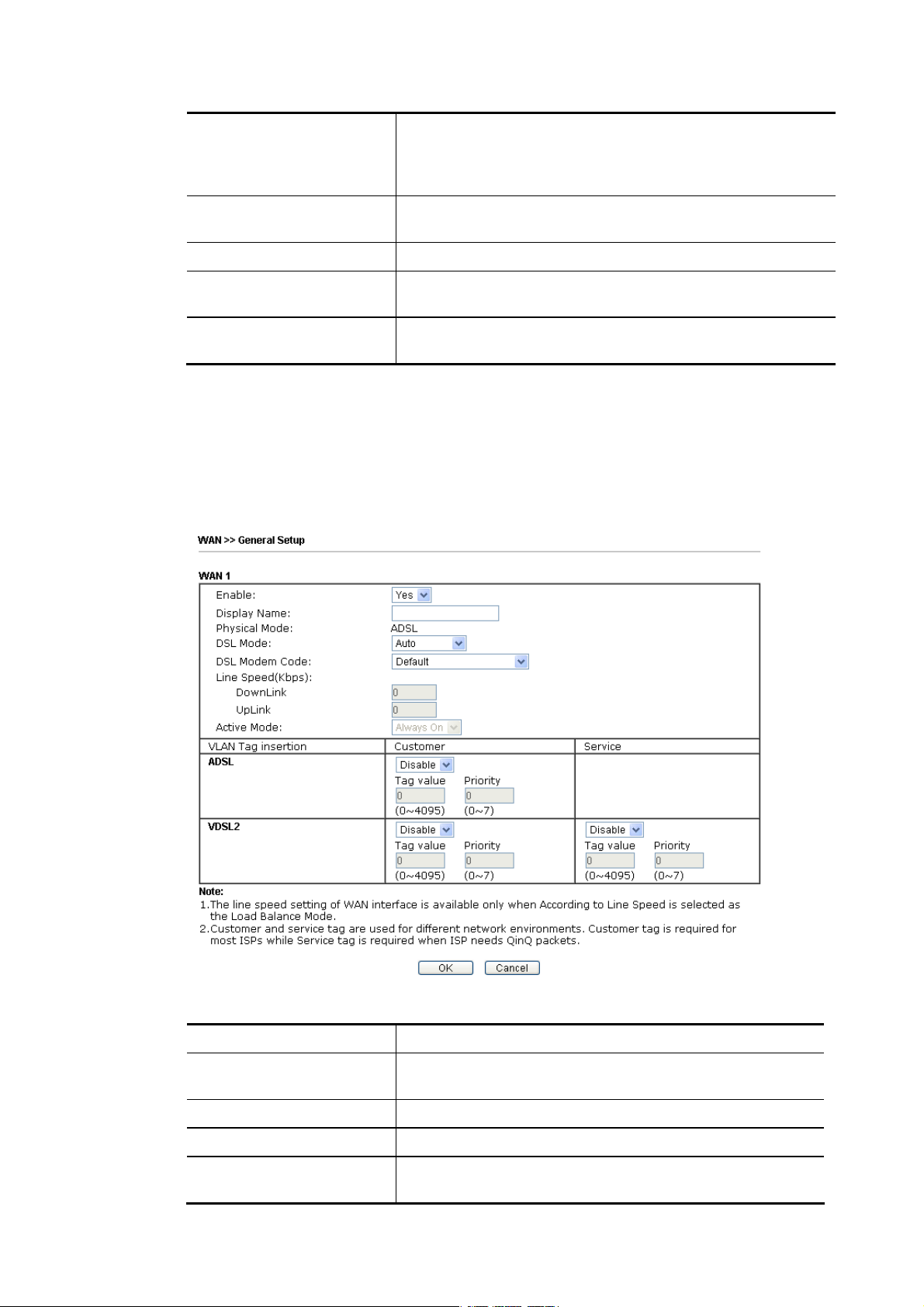
not open smoothly, especially the site need authentication,
e.g., FTP.
If you have no strong demand about speed test result, keep
default settings as IP based.
Index Click the WAN interface link under Index to access into the
WAN configuration page.
Enable V means such WAN interface is enabled and ready to be used.
Physical Mode / Type Display the physical mode and physical type of such WAN
interface.
Active Mode Display whether such WAN interface is Active device or
backup device.
After finished the above settings, click OK to save the settings.
IIII--11--11--11 WWAANN11 ((AADDSSLL//VVDDSSLL))
Vigor router will detect the physical line is connected by ADSL automatically. Therefore, this
page allows you to configure settings for ADSL at one time. That is, it is not necessary for you
to configure different profile settings for ADSL respectively.
Available settings are explained as follows:
Item Description
Enable Choose Yes to invoke the settings for this WAN interface.
Choose No to disable the settings for this WAN interface.
Display Name Type the description for such interface.
Physical Mode Display the physical mode of such interface.
DSL Mode Specify the physical mode (VDSL or ADSL) for such router
manually.
Vigor2762 Series User’s Guide
53
Page 66

4
DSL Modem Code Choose the correct DSL modem code for ensuring the
network connection.
If you have no idea about the selection, simply choose
Default or contact the dealer for assistance.
VLAN Tag insertion
(ADSL/VDSL)
Such feature is offered to the user with the environment
supporting IEEE_802.1ad. In which, service is used for outer
tag; customer is used for inner tag.
Enable – Enable the function of VLAN with tag.
The router will add specific VLAN number to all packets on
the WAN while sending them out.
Please type the tag value and specify the priority for the
packets sending by WAN1.
Disable – Disable the function of VLAN with tag.
Tag value – Type the value as the VLAN ID number. The
range is form 0 to 4095.
Priority – Type the packet priority number for such VLAN.
The range is from 0 to 7.
5
Vigor2762 Series User’s Guide
Page 67

IIII--11--11--22 WWAANN22 ((EEtthheerrnneett))
Ethernet is the Physical Mode for WAN2.
Available settings are explained as follows:
Item Description
Enable Choose Yes to invoke the settings for this WAN interface.
Choose No to disable the settings for this WAN interface.
Display Name Type the description for such WAN interface.
Physical Mode Display the physical mode of such WAN interface.
Physical Type You can change the physical type for
WAN1/WAN2/WAN3/WAN4 or choose Auto negotiation for
determined by the system.
Line Speed If your choose According to Line Speed as the Load
Balance Mode, please type the line speed for downloading
and uploading for such WAN interface. The unit is kbps.
VLAN Tag insertion Enable – Enable the function of VLAN with tag.
The router will add specific VLAN number to all packets on
the WAN while sending them out.
Please type the tag value and specify the priority for the
packets sending by WAN1.
Disable – Disable the function of VLAN with tag.
Tag value – Type the value as the VLAN ID number. The
range is form 0 to 4095.
Priority – Type the packet priority number for such VLAN.
The range is from 0 to 7.
Active Mode Choose Always On to make the WAN connection being
activated always.
If you choose Failover as the Active Mode, the option of
Vigor2762 Series User’s Guide
55
Page 68

Active When will appear.
Failover – Choose it to make the WAN connection as a
backup connection.
WAN Failure – When the active WAN failed, such WAN
will be activated as the main network connection.
Traffic Threshold – When the data traffic of active
WAN reaches the traffic threshold (specified here),
the failover WAN will be enabled automatically to
share the overloaded data traffic.
After finished the above settings, click OK to save the settings.
IIII--11--11--33 WWAANN33 // WWAANN44 ((UUSSBB))
To use 3G/4G network connection through 3G/4G USB Modem, please configure WAN3 or
WAN4 interface.
Available settings are explained as follows:
Item Description
Enable Choose Yes to invoke the settings for this WAN interface.
Choose No to disable the settings for this WAN interface.
Display Name Type the description for such WAN interface.
Physical Mode Display the physical mode of such WAN interface.
Line Speed If your choose According to Line Speed as the Load Balance
Mode, please type the line speed for downloading and
uploading for such WAN interface. The unit is kbps.
56
Vigor2762 Series User’s Guide
Page 69

7
Active Mode Choose Always On to make the WAN connection being
activated always.
If you choose Failover as the Active Mode, the option of
Active When will appear.
Failover – Choose it to make the WAN connection as a backup
connection.
WAN Failure – When the active WAN failed, such WAN
will be activated as the main network connection.
Traffic Threshold – When the data traffic of active
WAN reaches the traffic threshold (specified here), the
failover WAN will be enabled automatically to share the
overloaded data traffic.
After finished the above settings, click OK to save the settings.
Vigor2762 Series User’s Guide
5
Page 70

IIII--11--22 IInntteerrnneett AAcccceessss
For the router supports multi-WAN function, the users can set different WAN settings (for
WAN1/WAN2/WAN3) for Internet Access. Due to different Physical Mode for WAN interface,
the Access Mode for these connections also varies. Refer to the following figures.
And,
And,
Available settings are explained as follows:
Item Description
Index Display the WAN interface.
Display Name It shows the name of the WAN1/WAN2/WAN3 that entered in
general setup.
Physical Mode It shows the physical connection for WAN1~2 (Ethernet)
/WAN3 (3G/4G USB Modem) according to the real network
connection.
Access Mode Use the drop down list to choose a proper access mode. The
details page of that mode will be popped up. If not, click
Details Page for accessing the page to configure the settings.
Details Page This button will open different web page (based on IPv4)
according to the access mode that you choose in WAN
interface.
58
Vigor2762 Series User’s Guide
Page 71

9
Note that Details Page will be changed slightly based on
physical mode.
IPv6 This button will open different web page (based on Physical
Mode) to setup IPv6 Internet Access Mode for WAN interface.
If IPv6 service is active on this WAN interface, the color of
“IPv6” will become green.
DHCP Client Option This button allows you to configure DHCP client options.
DHCP packets can be processed by adding option number and
data information when such function is enabled and
configured.
Enable – Check the box to enable the function of DHCP
Option. Each DHCP option is composed by an option number
with data. For example,
Option number:100
Data: abcd
When such function is enabled, the specified values for DHCP
option will be seen in DHCP reply packets.
Interface – Specify the WAN interface(s) that will be
overwritten by such function. WAN5 ~ WAN7 can be located
under WAN>>Multi-PVC/VLAN.
Option Number – Type a number for such function.
DataType – Choose the type (ASCII or Hex) for the data to be
stored.
Data – Type the content of the data to be processed by the
function of DHCP option.
Info
If you choose to configure option 61 here, the detailed settings in WAN>>Internet
Access will be overwritten.
Vigor2762 Series User’s Guide
5
Page 72

0
IIII--11--22--11 DDeettaaiillss PPaaggee ffoorr PPPPPPooEE//PPPPPPooAA iinn WWAANN11 ((PPhhyyssiiccaall MMooddee:: AADDSSLL))
Available settings are explained as follows:
Item Description
Enable/Disable Click Enable for activating this function. If you click Disable,
this function will be closed and all the settings that you
adjusted in this page will be invalid.
Modem Settings Set up the DSL parameters required by your ISP. These
settings configured here are specified for ADSL only.
Multi-PVC channel - The selections displayed here are
determined by the page of WAN >> Multi-PVC/VLAN. Select
M-PVCs Channel means no selection will be chosen.
VPI - Type in the value provided by ISP.
VCI - Type in the value provided by ISP.
Encapsulating Type - Drop down the list to choose the type
provided by ISP.
Protocol - Drop down the list to choose the one (PPPoE or
PPPoA) provided by ISP.
If you have already used Quick Start Wizard to set the
protocol, then it is not necessary for you to change any
settings in this group.
Modulation –Default setting is Multimode. Choose the one
that fits the requirement of your router.
6
Vigor2762 Series User’s Guide
Page 73

PPPoE Pass-through The router offers PPPoE dial-up connection. Besides, you
also can establish the PPPoE connection directly from local
clients to your ISP via the Vigor router. When PPPoA protocol
is selected, the PPPoE package transmitted by PC will be
transformed into PPPoA package and sent to WAN server.
Thus, the PC can access Internet through such direction.
For Wired LAN – If you check this box, PCs on the same
network can use another set of PPPoE session (different with
the Host PC) to access into Internet.
For Wireless LAN – It is available for n model. If you check
this box, PCs on the same wireless network can use another
set of PPPoE session (different with the Host PC) to access
into Internet.
To have PPPoA Pass-through, please choose PPPoA protocol
and check the box(es) here. The router will behave like a
modem which only serves the PPPoE client on the LAN.
That’s, the router will offer PPPoA dial-up connection.
WAN Connection
Detection
Such function allows you to verify whether network
connection is alive or not through ARP Detect or Ping Detect.
Mode – Choose ARP Detect or Ping Detect for the system to
execute for WAN detection. If you choose Ping Detect as the
detection mode, you have to type required settings for the
following items.
Primary/Secondary Ping IP – If you choose Ping Detect as
detection mode, you have to type Primary or Secondary IP
address in this field for pinging.
Ping Gateway IP – If you choose Ping Detect as detection
mode, you also can enable this setting to use current WAN
gateway IP address for pinging.
With the IP address(es) pinging, Vigor router can check if
the WAN connection is on or off.
TTL (Time to Live) – Set TTL value of PING operation.
Ping Interval – Type the interval for the system to
execute the PING operation.
Ping Retry – Type the number of times that the system is
allowed to execute the PING operation before WAN
disconnection is judged.
MTU It means Max Transmit Unit for packet.
Path MTU Discovery – It is used to detect the maximum MTU
size of a packet not to be segmented in specific transmit
path.
Click Detect to open the following dialog.
Vigor2762 Series User’s Guide
61
Page 74

Path MTU to – Type the IP address as the specific
transmit path.
MTU reduce size by – It determines the decreasing size
of MTU value. For example, the number specified in
this field is “8”. The maximum MTU size is “1500”.
After clicking the “detect” button, the system will
calculate and get the suitable MTU value such as 1500,
1492, 1484 and etc., automatically.
Detect – Click it to detect a suitable MTU value
Accept – After clicking it, the detected value will be
displayed in the field of MTU.
ISP Access Setup Enter your allocated username, password and authentication
parameters according to the information provided by your
ISP.
Service Name - Enter the description of the specific network
service.
Username – Type in the username provided by ISP in this
field.
Password – Type in the pa ssword provided by ISP in this field.
Separate Account for ADSL – In default, WAN1 supports
VDSL2/ADSL and uses the same PPPoE account and password
for connection. If required, you can configure another
account and password for ADSL connection by checking this
box. If it is checked, the system will ask you to type another
group of account and password additionally.
PPP Authentication – Select PAP only or PAP or CHAP for
PPP.
IP Address From ISP Usually ISP dynamically assigns IP address to you each time
you connect to it and request. In some case, your ISP
provides service to always assign you the same IP address
whenever you request. In this case, you can fill in this IP
address in the Fixed IP field. Please contact your ISP before
you want to use this function.
WAN IP Alias - If you have multiple public IP addresses and
would like to utilize them on the WAN interface, please use
WAN IP Alias. You can set up to 8 public IP addresses other
than the current one you are using.
62
Vigor2762 Series User’s Guide
Page 75
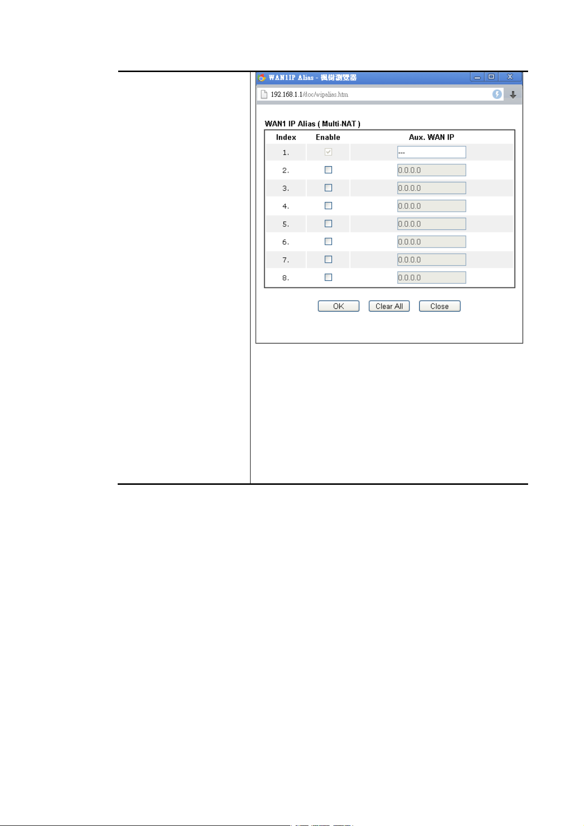
Fixed IP – Click Yes to use this function and type in a fixed IP
address in the box of Fixed IP Address.
Default MAC Address – You can use Default MAC Address or
specify another MAC address by typing on the boxes of MAC
Address for the router.
Specify a MAC Address – Type the MAC address for the router
manually.
Index (1-15) in Schedule Setup - You can type in four sets of
time schedule for your request. All the schedules can be set
previously in Applications >> Schedule web page and you
can use the number that you have set in that web page.
IIII--11--22--22 DDeettaaiillss PPaaggee ffoorr MMppooAA//SSttaattiicc oorr DDyynnaammiicc IIPP iinn WWAANN11 ((PPhhyyssiiccaall MMooddee::
AADDSSLL))
MPoA is a specification that enables ATM services to be integrated with existing LANs, which
use either Ethernet, token-ring or TCP/IP protocols. The goal of MPoA is to allow different
LANs to send packets to each other via an ATM backbone.
To use MPoA / Static or Dynamic IP as the accessing protocol of t h e I n ternet, select MPoA /
Static or Dynamic IP from the WAN>>Internet Access >>WAN1 page. The following web page
will appear.
Vigor2762 Series User’s Guide
63
Page 76

4
Available settings are explained as follows:
Item Description
Enable/Disable Click Enable for activating this function. If you click Disable,
this function will be closed and all the settings that you
adjusted in this page will be invalid.
Modem Settings Set up the DSL parameters required by your ISP. These
settings configured here are specified for ADSL only.
Multi-PVC channel - The selections displayed here are
determined by the page of Internet Access >>Multi PVCs.
Select M-PVCs Channel means no selection will be chosen.
Encapsulation - Drop down the list to choose the type
provided by ISP.
VPI - Type in the value provided by ISP.
VCI - Type in the value provided by ISP.
Modulation –Default setting is Multimode. Choose the one
that fits the requirement of your router.
WAN Connection
Detection
Such function allows you to verify whether network
connection is alive or not through ARP Detect or Ping Detect.
Mode – Choose ARP Detect or Ping Detect or Always On for
the system to execute for WAN detection. If you choose Ping
Detect as the detection mode, you have to type required
settings for the following items.
Primary/Secondary Ping IP – If you choose Ping Detect as
detection mode, you have to type Primary or Secondary IP
address in this field for pinging.
6
Vigor2762 Series User’s Guide
Page 77

Ping Gateway IP – If you choose Ping Detect as detection
mode, you also can enable this setting to use current WAN
gateway IP address for pinging. With the IP address(es)
pinging, Vigor router can check if the WAN connection is
on or off.
TTL (Time to Live) – Set TTL value of PING operation.
Ping Interval – Type the interval for the system to
execute the PING operation.
Ping Retry – Type the number of times that the system is
allowed to execute the PING operation before WAN
disconnection is judged.
MTU It means Max Transmit Unit for packet.
Path MTU Discovery – It is used to detect the maximum MTU
size of a packet not to be segmented in specific transmit
path.
Click Detect to open the following dialog.
Path MTU to – Type the IP address as the specific
transmit path.
MTU reduce size by – It determines the decreasing size
of MTU value. For example, the number specified in
this field is “8”. The maximum MTU size is “1500”.
After clicking the “detect” button, the system will
calculate and get the suitable MTU value such as 1500,
1492, 1484 and etc., automatically.
Detect – Click it to detect a suitable MTU value
Accept – After clicking it, the detected value will be
displayed in the field of MTU.
RIP Protocol
Bridge Mode Enable Bridge Mode - If the function is enabled, the router
WAN IP Network Settings This group allows you to obtain an IP address automatically
Routing Information Protocol is abbreviated as RIP(RFC1058)
specifying how routers exchange routing tables information.
Click Enable RIP for activating this function.
will work as a bridge modem.
and allows you type in IP address manually.
WAN IP Alias - If you have multiple public IP addresses and
would like to utilize them on the WAN interface, please use
WAN IP Alias. You can set up to 8 public IP addresses other
than the current one you are using. Notice that this setting is
available for WAN1 only. Type the additional WAN IP address
and check the Enable box. Then click OK to exit the dialog.
Vigor2762 Series User’s Guide
65
Page 78

Obtain an IP address automatically – Click this button to
obtain the IP address automatically.
Router Name – Type in the router name provided
by ISP.
Domain Name – Type in the domain name that y ou
have assigned.
DHCP Client Identifier for some ISP -
Enable: Check the box to specify username and
password as the DHCP client identifier for some
ISP.
Username: Type a name as username. The
maximum length of the user name you can set is
63 characters.
Password: Type a password. The maximum length
of the password you can set is 62 characters.
Specify an IP address – Click this radio button to specify
some data.
IP Address – Type in the private IP address.
Subnet Mask – Type in the subnet mask.
Gateway IP Address – Type in gateway IP address.
Default MAC Address – Type in MAC address for the router.
You can use Default MAC Address or specify another MAC
address for your necessity.
Specify a MAC Address – Type in the MAC address for the
router manually.
DNS Server IP Address Type in the primary IP address for the router. If necessary,
type in secondary IP address for necessity in the future.
After finishing all the settings here, please click OK to activate them.
66
Vigor2762 Series User’s Guide
Page 79

7
IIII--11--22--33 DDeettaaiillss PPaaggee ffoorr PPPPPPooEE iinn EEtthheerreenneett WWAANN
To choose PPPoE as the accessing protocol of the Internet, please select PPPoE from the
WAN>>Internet Access >>WAN1 page. The following web page will be shown.
Available settings are explained as follows:
Item Description
Enable/Disable Click Enable for activating this function. If you click Disable,
this function will be closed and all the settings that you
adjusted in this page will be invalid.
ISP Access Setup Enter your allocated username, password and authentication
parameters according to the information provided by your
ISP.
Service Name (Optional) - Enter the description of the
specific network service.
Username – Type in the username provided by ISP in this
field.
The maximum length of the user name you can set is 63
characters.
Password – Type in the pa ssword provided by ISP in this field.
The maximum length of the password you can set is 62
characters.
Index (1-15) in Schedule Setup - You can type in four sets of
time schedule for your request. All the schedules can be set
previously in Application >> Schedule web page and you can
use the number that you have set in that web page.
Vigor2762 Series User’s Guide
6
Page 80

WAN Connection
Detection
Such function allows you to verify whether network
connection is alive or not through ARP Detect or Ping Detect.
Mode – Choose ARP Detect or Ping Detect for the system to
execute for WAN detection. If you choose Ping Detect as the
detection mode, you have to type required settings for the
following items.
Primary/Secondary Ping IP – If you choose Ping Detect as
detection mode, you have to type Primary or Secondary IP
address in this field for pinging.
Ping Gateway IP – If you choose Ping Detect as detection
mode, you also can enable this setting to use current WAN
gateway IP address for pinging. With the IP address(es)
pinging, Vigor router can check if the WAN connection is
on or off.
TTL (Time to Live) – Set TTL value of PING operation.
Ping Interval – Type the interval for the system to
execute the PING operation.
Ping Retry – Type the number of times that the system is
allowed to execute the PING operation before WAN
disconnection is judged.
MTU It means Max Transmit Unit for packet.
Path MTU Discovery – It is used to detect the maximum MTU
size of a packet not to be segmented in specific transmit
path.
Click Detect to open the following dialog.
68
Path MTU to – Type the IP address as the specific
transmit path.
MTU reduce size by – It determines the decreasing size
of MTU value. For example, the number specified in
this field is “8”. The maximum MTU size is “1500”.
After clicking the “detect” button, the system will
calculate and get the suitable MTU value such as 1500,
1492, 1484 and etc., automatically.
Detect – Click it to detect a suitable MTU value
Accept – After clicking it, the detected value will be
displayed in the field of MTU.
TTL Change the TTL value – Enable or disable the TTL (Time to
Live) for a packet transmitted through Vigor router.
Enable - TTL value will be reduced (-1) when it passess
through Vigor router. It will cause the client, accessing
Internet through Vigor router, be blocked by certain ISP
when TTL value becomes “0”.
Disable – TTL value will not be reduced. Then, when a packet
passes through Vigor router, it will not be cancelled. That is,
the client who sends out the packet will not be blocked by
Vigor2762 Series User’s Guide
Page 81
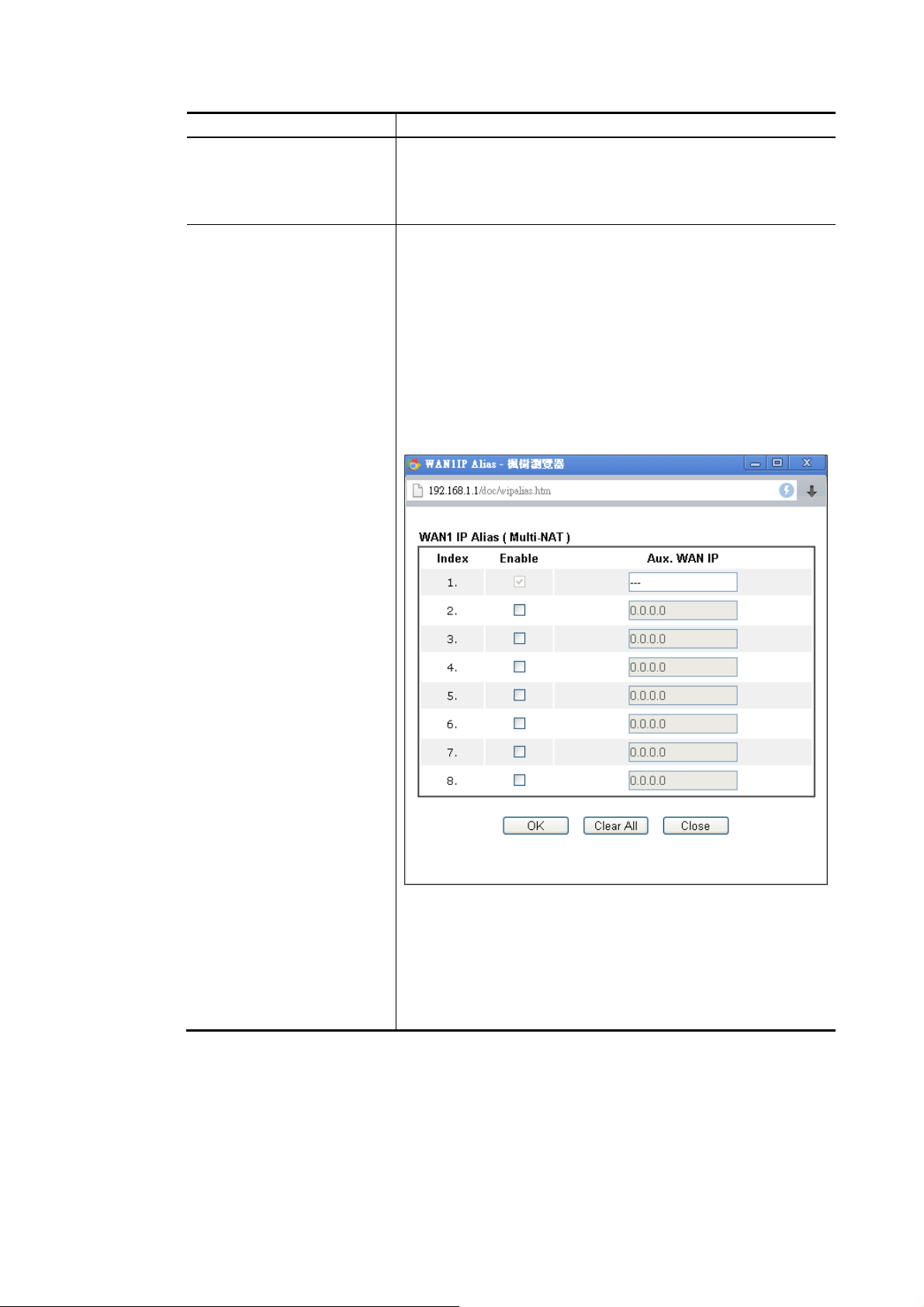
9
ISP.
PPP/MP Setup PPP Authentication – Select PAP only or PAP or CHAP for
PPP.
Idle Timeout – Set the timeout for breaking down the
Internet after passing through the time without any action.
IP Address Assignment
Method (IPCP)
Usually ISP dynamically assigns IP address to you each time
you connect to it and request. In some case, your ISP
provides service to always assign you the same IP address
whenever you request. In this case, you can fill in this IP
address in the Fixed IP field. Please contact your ISP before
you want to use this function.
WAN IP Alias - If you have multiple public IP addresses and
would like to utilize them on the WAN interface, please use
WAN IP Alias. You can set up to 8 public IP addresses other
than the current one you are using. Type the additional WAN
IP address and check the Enable box. Then click OK to exit
the dialog.
Fixed IP – Click Yes to use this function and type in a fixed IP
address in the box of Fixed IP Address.
Default MAC Address – You can use Default MAC Address or
specify another MAC address by typing on the boxes of MAC
Address for the router.
Specify a MAC Address – Type the MAC address for the router
manually.
After finishing all the settings here, please click OK to activate them.
IIII--11--22--44 DDeettaaiillss PPaaggee ffoorr SSttaattiicc oorr DDyynnaammiicc IIPP iinn EEtthheerreenneett WWAANN
For static IP mode, you usually receive a fixed public IP address or a public subnet, namely
multiple public IP addresses from your DSL or Cable ISP service providers. In most cases, a
Cable service provider will offer a fixed public IP, while a DSL service pr ovider will offer a
public subnet. If you have a public subnet, you could assign an IP address or many IP address
to the WAN interface.
Vigor2762 Series User’s Guide
6
Page 82

0
To use Static or Dynamic IP as the accessing protocol of the internet, please click the Static
or Dynamic IP tab. The following web page will be shown.
Available settings are explained as follows:
Item Description
Enable / Disable Click Enable for activating this function. If you click Disable,
this function will be closed and all the settings that you
adjusted in this page will be invalid.
Keep WAN Connection Normally, this function is designed for Dynamic IP
environments because some ISPs will drop connections if
there is no traffic within certain periods of time. Check
Enable PING to keep alive box to activate this function.
PING to the IP - If you enable the PING function, please
specify the IP address for the system to PING it for keeping
alive.
PING Interval - Enter the interval for the system to execute
the PING operation.
WAN Connection
Detection
Such function allows you to verify whether network
connection is alive or not through ARP Detect or Ping Detect.
Mode – Choose ARP Detect or Ping Detect or Always On for
the system to execute for WAN detection. If you choose Ping
Detect as the detection mode, you have to type required
settings for the following items.
Primary/Secondary Ping IP – If you choose Ping Detect as
detection mode, you have to type Primary or Secondary IP
address in this field for pinging.
7
Vigor2762 Series User’s Guide
Page 83

Ping Gateway IP – If you choose Ping Detect as detection
mode, you also can enable this setting to use current WAN
gateway IP address for pinging. With the IP address(es)
pinging, Vigor router can check if the WAN connection is
on or off.
TTL (Time to Live) – Set TTL value of PING operation.
Ping Interval – Type the interval for the system to
execute the PING operation.
Ping Retry – Type the number of times that the system is
allowed to execute the PING operation before WAN
disconnection is judged.
MTU It means Max Transmit Unit for packet.
Path MTU Discovery – It is used to detect the maximum MTU
size of a packet not to be segmented in specific transmit
path.
Click Detect to open the following dialog.
Path MTU to – Type the IP address as the specific
transmit path.
MTU reduce size by – It determines the decreasing size
of MTU value. For example, the number specified in
this field is “8”. The maximum MTU size is “1500”.
After clicking the “detect” button, the system will
calculate and get the suitable MTU value such as 1500,
1492, 1484 and etc., automatically.
Detect – Click it to detect a suitable MTU value
Accept – After clicking it, the detected value will be
displayed in the field of MTU.
RIP Protocol
TTL Change the TTL value – Enable or disable the TTL (Time to
Routing Information Protocol is abbreviated as RIP(RFC1058)
specifying how routers exchange routing tables information.
Click Enable RIP for activating this function.
Live) for a packet transmitted through Vigor router.
Enable - TTL value will be reduced (-1) when it passess
through Vigor router. It will cause the client, accessing
Internet through Vigor router, be blocked by certain ISP
when TTL value becomes “0”.
Disable – TTL value will not be reduced. Then, when a packet
passes through Vigor router, it will not be cancelled. That is,
the client who sends out the packet will not be blocked by
ISP.
WAN IP Network Settings This group allows you to obtain an IP address automatically
and allows you type in IP address manually.
WAN IP Alias - If you have multiple public IP addresses and
would like to utilize them on the WAN interface, please use
Vigor2762 Series User’s Guide
71
Page 84

WAN IP Alias. You can set up to 8 public IP addresses other
than the current one you are using.
Obtain an IP address automatically – Click this button to
obtain the IP address automatically if you want to use
Dynamic IP mode.
Router Name: Type in the router name provided
by ISP.
Domain Name: Type in the domain name that you
have assigned.
DHCP Client Identifier for some ISP
Enable: Check the box to specify username and
password as the DHCP client identifier for some
ISP.
Username: Type a name as username. The
maximum length of the user name you can set is
63 characters.
Password: Type a password. The maximum length
of the password you can set is 62 characters.
Specify an IP address – Click this radio button to specify
some data if you want to use Static IP mode.
IP Address: Type the IP address.
Subnet Mask: Type the subnet mask.
Gateway IP Address: Type the gateway IP
address.
Default MAC Address: Click this radio button to use default
MAC address for the router.
Specify a MAC Address: Some Cable service providers
specify a specific MAC address for access authentication. In
such cases you need to click the Specify a MAC Address and
enter the MAC address in the MAC Address field.
DNS Server IP Address Type in the primary IP address for the router if you want to
use Static IP mode. If necessary, type in secondary IP address
72
Vigor2762 Series User’s Guide
Page 85

for necessity in the future.
After finishing all the settings here, please click OK to activate them.
IIII--11--22--55 DDeettaaiillss PPaaggee ffoorr PPPPTTPP//LL22TTPP iinn EEtthheerreenneett WWAANN
To use PPTP/L2TP as the accessing protocol of the internet, please click the PPTP/L2TP tab.
The following web page will be shown.
Available settings are explained as follows:
Item Description
PPTP/L2TP Enable PPTP- Click this radio button to enable a PPTP client
to establish a tunnel to a DSL modem on the WAN interface.
Enable L2TP - Click this radio button to enable a L2TP client
to establish a tunnel to a DSL modem on the WAN interface.
Disable – Click this radio button to close the connection
through PPTP or L2TP.
Server Address - Specify the IP address of the PPTP/L2TP
server if you enable PPTP/L2TP client mode.
Specify Gateway IP Address – Specify the gateway IP address
for DHCP server.
ISP Access Setup Username -Type in the username provided by ISP in this
field. The maximum length of the user name you can set is 63
characters.
Password -Type in the password provided by ISP in this field.
The maximum length of the password you can set is 62
characters.
Index (1-15) in Schedule Setup - You can type in four sets of
time schedule for your request. All the schedules can be set
previously in Application >> Schedule web page and you can
use the number that you have set in that web page.
MTU It means Max Transmit Unit for packet.
Vigor2762 Series User’s Guide
73
Page 86

4
Path MTU Discovery – It is used to detect the maximum MTU
size of a packet not to be segmented in specific transmit
path.
Click Detect to open the following dialog.
Path MTU to – Type the IP address as the specific
transmit path.
MTU reduce size by – It determines the decreasing size
of MTU value. For example, the number specified in
this field is “8”. The maximum MTU size is “1500”.
After clicking the “detect” button, the system will
calculate and get the suitable MTU value such as 1500,
1492, 1484 and etc., automatically.
Detect – Click it to detect a suitable MTU value
Accept – After clicking it, the detected value will be
displayed in the field of MTU.
PPP Setup PPP Authentication - Select PAP only or PAP or CHAP for
PPP.
Idle Timeout - Set the timeout for breaking down the
Internet after passing through the time without any action.
IP Address Assignment
Method(IPCP)
WAN IP Network Settings Obtain an IP address automatically – Click this button to
WAN IP Alias - If you have multiple public IP addresses and
would like to utilize them on the WAN interface, please use
WAN IP Alias. You can set up to 8 public IP addresses other
than the current one you are using.
Fixed IP - Usually ISP dynamically assigns IP address to you
each time you connect to it and request. In some case, your
ISP provides service to always assign you the same IP address
whenever you request. In this case, you can fill in this IP
address in the Fixed IP field. Please contact your ISP before
you want to use this function. Click Yes to use this function
and type in a fixed IP address in the box.
Fixed IP Address -Type a fixed IP address.
obtain the IP address automatically.
Specify an IP address – Click this radio button to specify
some data.
IP Address – Type the IP address.
Subnet Mask – Type the subnet mask.
After finishing all the settings here, please click OK to activate them.
7
Vigor2762 Series User’s Guide
Page 87
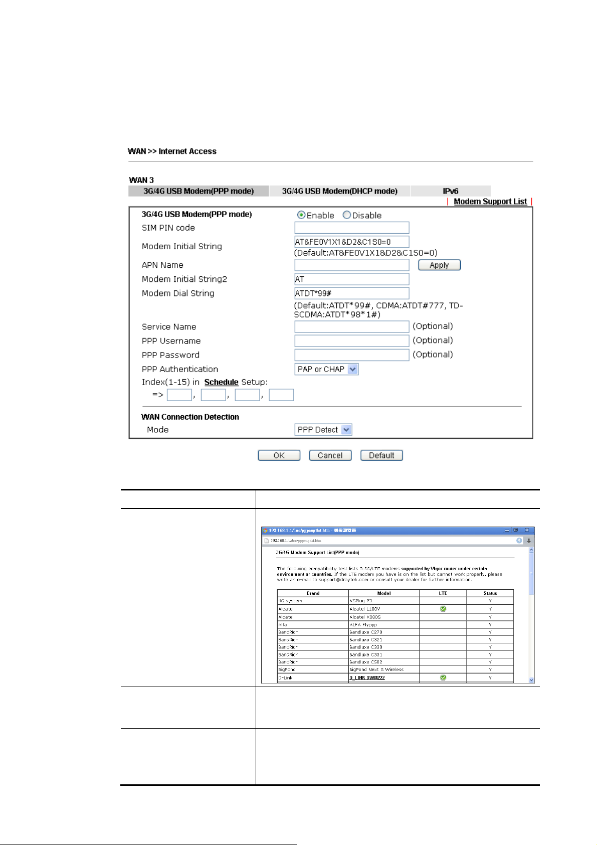
IIII--11--22--66 DDeettaaiillss PPaaggee ffoorr 33GG//44GG UUSSBB MMooddeemm ((PPPPPP mmooddee)) iinn UUSSBB WWAANN
To use 3G/4G USB Modem (PPP mode) as the accessing protocol of the internet, please
choose Internet Access from WAN menu. Then, select 3G/4G USB Modem (PPP mode) for
WAN5. The following web page will be shown.
Available settings are explained as follows:
Item Description
Modem Support List It lists all of the mode ms supported by such router.
3G /4G USB Modem (PPP
mode)
SIM PIN code Type PIN code of the SIM card that will be used to access
Click Enable for activating this function. If you click Disable,
this function will be closed and all the settings that you
adjusted in this page will be invalid.
Internet.
The maximum length of the PIN code you can set is 15
characters.
Vigor2762 Series User’s Guide
75
Page 88

Modem Initial String Such value is used to initialize USB modem. Please use the
default value. If you have any question, please contact to
your ISP.
The maximum length of the string you can set is 47
characters.
APN Name APN means Access Point Name which is provided and
required by some ISPs. Type the name and click Apply.
The maximum length of the name you can set is 43
characters.
Modem Initial String2 The initial string 1 is shared with APN.
In some cases, user may need another initial AT c ommand t o
restrict 3G band or do any special settings.
The maximum length of the string you can set is 47
characters.
Modem Dial String Such value is used to dial through USB mode. Please use the
default value. If you have any question, please contact to
your ISP.
The maximum length of the string you can set is 31
characters.
Service Name Enter the description of the specific network service.
PPP Username Type the PPP username (optional). The maximum length of
the name you can set is 63 characters.
PPP Password Type the PPP password (optional). The maximum length of
the password you can set is 62 characters.
PPP Authentication Select PAP only or PAP or CHAP for PPP.
Index (1-15) in Schedule
Setup
WAN Connection
Detection
You can type in four sets of time schedule for your request.
All the schedules can be set previously in Application >>
Schedule web page and you can use the number that you
have set in that web page
Such function allows you to verify whether network
connection is alive or not through ARP Detect or Ping Detect.
Mode – Choose PPP Detect or Ping Detect for the system to
execute for WAN detection. If you choose Ping Detect as the
detection mode, you have to type required settings for the
following items.
Primary/Secondary Ping IP – If you choose Ping Detect as
detection mode, you have to type Primary or Secondary IP
address in this field for pinging.
TTL (Time to Live) – Set TTL value of PING operation.
Ping Interval – Type the interval for the system to
execute the PING operation.
Ping Retry – Type the number of times that the system is
allowed to execute the PING operation before WAN
disconnection is judged.
After finishing all the settings here, please click OK to activate them.
76
Vigor2762 Series User’s Guide
Page 89
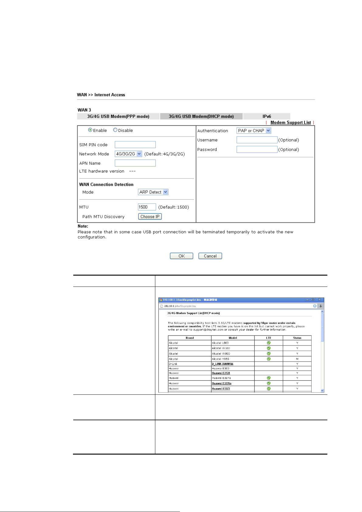
7
IIII--11--22--77 DDeettaaiillss PPaaggee ffoorr 33GG//44GG UUSSBB MMooddeemm ((DDHHCCPP mmooddee)) iinn UUSSBB WWAANN
To use 3G/4G USB Modem (DHCP mode) as the accessing protocol of the intern et, please
choose Internet Access from WAN menu. Then, select 3G/4G USB Modem (DHCP mode) for
WAN3/WAN4. The following web page will be shown.
Available settings are explained as follows:
Item Description
Modem Support List It lists all of the mode ms supported by such router.
3G/4G USB Modem (DHCP
mode)
SIM PIN code Type PIN code of the SIM card that will be used to access
Click Enable for activating this function. If you click Disable,
this function will be closed and all the settings that you
adjusted in this page will be invalid.
Internet.
The maximum length of the PIN code you can set is 19
characters.
Vigor2762 Series User’s Guide
7
Page 90

Network Mode Force Vigor router to connect Internet with the mode
specified here. If you choose 4G/3G/2G as network mode,
the router will choose a suitable one according to the actual
wireless signal automatically.
APN Name APN means Access Point Name which is provided and
required by some ISPs. Type the name and click Apply.
The maximum length of the name you can set is 47
characters.
WAN Connection
Detection
Such function allows you to verify whether network
connection is alive or not through ARP Detect or Ping Detect.
Mode – Choose ARP Detect or Ping Detect for the system to
execute for WAN detection. If you choose Ping Detect as the
detection mode, you have to type required settings for the
following items.
Primary/Secondary Ping IP – If you choose Ping Detect as
detection mode, you have to type Primary or Secondary IP
address in this field for pinging.
Ping Gateway IP – If you choose Ping Detect as detection
mode, you also can enable this setting to use current WAN
gateway IP address for pinging. With the IP address(es)
pinging, Vigor router can check if the WAN connection is
on or off.
TTL (Time to Live) – Set TTL value of PING operation.
Ping Interval – Type the interval for the system to
execute the PING operation.
Ping Retry – Type the number of times that the system is
allowed to execute the PING operation before WAN
disconnection is judged.
MTU It means Max Transmit Unit for packet.
Path MTU Discovery – It is used to detect the maximum MTU
size of a packet not to be segmented in specific transmit
path.
Click Detect to open the following dialog.
Path MTU to – Type the IP address as the specific
transmit path.
MTU reduce size by – It determines the decreasing size
of MTU value. For example, the number specified in
this field is “8”. The maximum MTU size is “1500”.
After clicking the “detect” button, the system will
calculate and get the suitable MTU value such as 1500,
1492, 1484 and etc., automatically.
Detect – Click it to detect a suitable MTU value
Accept – After clicking it, the detected value will be
displayed in the field of MTU.
78
Vigor2762 Series User’s Guide
Page 91
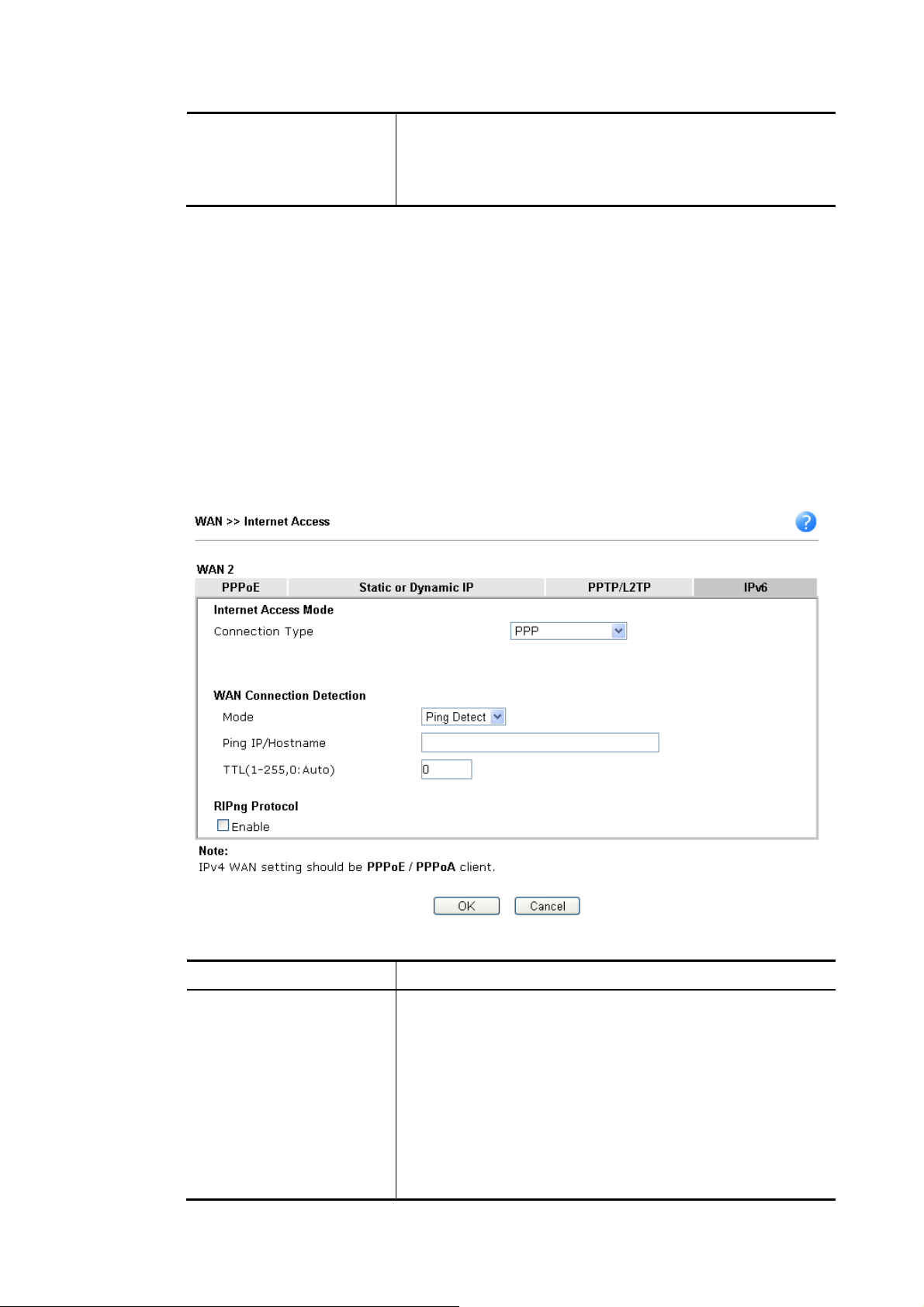
9
Authentication Select PAP only or PAP or CHAP for PPP authentication.
Username – Type the username for authentication
(optional).
Password – Type the password for authentication (optional).
After finishing all the settings here, please click OK to activate them.
IIII--11--22--88 DDeettaaiillss PPaaggee ffoorr IIPPvv66
When Offline is selected, the IPv6 connection will be disabled.
IIII--11--22--99 DDeettaaiillss PPaaggee ffoorr IIPPvv66
During the procedure of IPv4 PPPoE connection, we can get the IPv6 Link Local Address
between the gateway and Vigor router through IPv6CP. Later, use DHCPv6 or accept RA to
acquire the IPv6 prefix address (such as: 2001:B010:7300:200::/64) offered by the ISP. In
addition, PCs under LAN also can have the public IPv6 address for Internet access by means of
the generated prefix.
No need to type any other information for PPP mode.
–
–
OOfffflliinnee iinn WWAANN11//WWAANN22//WWAANN33
–
–
PPPPPP iinn WWAANN11//WWAANN22
Available settings are explained as follows:
Item Description
WAN Connection
Detection
Such function allows you to verify whether network
connection is alive or not through Ping Detect.
Mode – Choose Always On or Ping Detect for the system to
execute for WAN detection. Always On means no detection
will be executed. The network connection will be on always.
Ping IP/Hostname – If you choose Ping Detect as
detection mode, you have to type IP address in this field
for pinging.
TTL (Time to Live) –If you choose Ping Detect as
detection mode, you have to type TTL value.
Vigor2762 Series User’s Guide
7
Page 92

RIPng Protocol RIPng (RIP next generation) offers the same functions and
benefits as IPv4 RIP v2.
Below shows an example for successful IPv6 connection based on PPP mode.
Info
IIII--11--22--1100 DDeettaaiillss PPaaggee ffoorr IIPPvv66
Tunnel setup protocol client (TSPC) is an application which could help you to connect to IPv6
network easily.
Please make sure your IPv4 WAN connection is OK and apply one free account from hexago
(http://gogonet.gogo6.com/page/freenet6-account ) before you try to use TSPC for network
connection. TSPC would connect to tunnel broker and requests a tunnel according to the
specifications inside the configuration file. It gets a public IPv6 IP address and an IPv6 prefix
from the tunnel broker and then monitors the state of the tunnel in background.
After getting the IPv6 prefix and starting router advertisement daemon (RADVD), the PC
behind this router can directly connect to IPv6 the Internet.
At present, the IPv6 prefix can be acquired via the PPPoE mode connection which is
available for the areas such as Taiwan (hinet), the Netherlands, Australia and UK.
–
–
TTSSPPCC iinn WWAANN11//WWAANN22//WWAANN33
80
Vigor2762 Series User’s Guide
Page 93

Available settings are explained as follows:
Item Description
Username Type the name obtained from the broker. It is suggested for
you to apply another username and password for
http://gogonet.gogo6.com/page/freenet6-account.
The maximum length of the name you can set is 63
characters.
Password Type the password assigned with the user name.
The maximum length of the name you can set is 19
characters.
Tunnel Broker Type the address for the tunnel broker IP, FQDN or an
optional port number.
WAN Connection
Detection
Such function allows you to verify whether network
connection is alive or not through Ping Detect.
Mode – Choose Always On or Ping Detect for the system to
execute for WAN detection. Always On means no detection
will be executed. The network connection will be on always.
Ping IP/Hostname – If you choose Ping Detect as
detection mode, you have to type IP address in this field
for pinging.
TTL (Time to Live) –If you choose Ping Detect as
detection mode, you have to type TTL value.
After finished the above settings, click OK to save the settings.
IIII--11--22--1111 DDeettaaiillss PPaaggee ffoorr IIPPvv66
Vigor2762 Series User’s Guide
–
–
AAIICCCCUU iinn WWAANN11//WWAANN22//WWAANN33
81
Page 94

Available settings are explained as follows:
Item Description
Always On Check this box to keep the network connection always.
Username Type the name obtained from the broker. Please apply new
account at http://www.sixxs.net/. It is suggested for you to
apply another username and password.
The maximum length of the name you can set is 19
characters.
Password Type the password assigned with the user name.
The maximum length of the password you can set is 19
characters.
Tunnel Broker It means a server of AICCU. The server can provide IPv6
tunnels to sites or end users over IPv4.
Type the address for the tunnel broker IP, FQDN or an
optional port number.
Tunnel ID One user account may have several tunnels. And, each
tunnel shall have one specified tunnel ID (e.g., T115394).
Type the ID offered by Tunnel Broker.
Subnet Prefix Type the subnet prefix address obtained from service
provider.
The maximum length of the prefix you can set is 128
characters.
82
Vigor2762 Series User’s Guide
Page 95

WAN Connection
Detection
Such function allows you to verify whether network
connection is alive or not through Ping Detect.
Mode – Choose Always On or Ping Detect for the system to
execute for WAN detection.
Ping IP/Hostname – If you choose Ping Detect as
detection mode, you have to type IP address in this field
for pinging.
TTL (Time to Live) –If you choose Ping Detect as
detection mode, you have to type TTL value.
After finished the above settings, click OK to save the settings.
Vigor2762 Series User’s Guide
83
Page 96

4
IIII--11--22--1122 DDeettaaiillss PPaaggee ffoorr IIPPvv66
DHCPv6 client mode would use DHCPv6 protocol to obtain IPv6 address from server.
–
–
DDHHCCPPvv66 CClliieenntt iinn WWAANN11//WWAANN22
Available settings are explained as follows:
Item Description
IAID Type a number as IAID.
WAN Connection
Detection
Such function allows you to verify whether network
connection is alive or not through NS Detect or Ping Detect.
Mode – Choose Always On, Ping Detect or NS Detect for the
system to execute for WAN detection. With NS Detect mode,
the system will check if network connection is established or
not, like IPv4 ARP Detect. Always On means no detection
will be executed. The network connection will be on always.
Ping IP/Hostname – If you choose Ping Detect as
detection mode, you have to type IP address in this field
for pinging.
TTL (Time to Live) –If you choose Ping Detect as
detection mode, you have to type TTL value.
RIPng Protocol RIPng (RIP next generation) offers the same functions and
benefits as IPv4 RIP v2.
Bridge Mode Enable Bridge Mode - If the function is enabled, the router
will work as a bridge modem.
Enable Firewall – It is available when Bridge Mode is
enabled. When both Bridge Mode and Firewall check boxes
are enabled, the settings configured (user profiles) under
8
Vigor2762 Series User’s Guide
Page 97

User Management will be ignored. And all of the filter rules
defined and enabled in Firewall menu will be activated.
Bridge Subnet – Make a bridge between the selected LAN
subnet and such WAN interface.
After finished the above settings, click OK to save the settings.
IIII--11--22--1133 DDeettaaiillss PPaaggee ffoorr IIPPvv66
This type allows you to setup static IPv6 address for WAN interface.
–
–
SSttaattiicc IIPPvv66 iinn iinn WWAANN11//WWAANN22
Available settings are explained as follows:
Item Description
Static IPv6 Address
Configuration
Vigor2762 Series User’s Guide
IPv6 Address – Type the IPv6 Static IP Address.
Prefix Length – Type the fixed value for prefix length.
Add – Click it to add a new entry.
Update – Click it to modify an existed entry.
Delete – Click it to remove an existed entry.
85
Page 98

Current IPv6 Address
Table
Static IPv6 Gateway
Configuration
WAN Connection
Detection
Display current interface IPv6 address.
IPv6 Gateway Address - Type your IPv6 gateway address
here.
Such function allows you to verify whether network
connection is alive or not through Ping Detect.
Mode – Choose Always On or Ping Detect or NS Detect for
the system to execute for WAN detection. Always On means
no detection will be executed. The network connection will
be on always.
Ping IP/Hostname – If you choose Ping Detect as
detection mode, you have to type IP address in this field
for pinging.
TTL (Time to Live) –If you choose Ping Detect as
detection mode, you have to type TTL value.
RIPng Protocol RIPng (RIP next generation) offers the same functions and
benefits as IPv4 RIP v2.
Bridge Mode Enable Bridge Mode - If the function is enabled, the router
will work as a bridge modem.
Enable Firewall – It is available when Bridge Mode is
enabled. When both Bridge Mode and Firewall check boxes
are enabled, the settings configured (user profiles) under
User Management will be ignored. And all of the filter rules
defined and enabled in Firewall menu will be activated.
Bridge Subnet – Make a bridge between the selected LAN
subnet and such WAN interface.
After finished the above settings, click OK to save the settings.
IIII--11--22--1144 DDeettaaiillss PPaaggee ffoorr IIPPvv66
This type allows you to setup 6in4 Static Tunnel for WAN interface.
Such mode allows the router to access IPv6 network through IPv4 network.
However, 6in4 offers a prefix outside of 2002::0/16. So, you can u se a f ixed endpoint rather
than anycast endpoint. The mode has more reliability.
–
–
66iinn44 SSttaattiicc TTuunnnneell iinn WWAANN11 // WWAANN22
86
Vigor2762 Series User’s Guide
Page 99

7
Available settings are explained as follows:
Item Description
Remote Endpoint IPv4
Address
6in4 IPv6 Address Type the static IPv6 address for IPv4 tunnel with the value
LAN Routed Prefix Type the static IPv6 address for LAN routing with the value
Tunnel TTL Type the number for the data lifetime in tunnel.
WAN Connection
Detection
Type the static IPv4 address for the remote server.
for prefix length.
for prefix length.
Such function allows you to verify whether network
connection is alive or not through Ping Detect.
Mode – Choose Always On or Ping Detect for the system to
execute for WAN detection. Always On means no detection
will be executed. The network connection will be on always.
Ping IP/Hostname – If you choose Ping Detect as
detection mode, you have to type IP address in this field
for pinging.
TTL (Time to Live) –If you choose Ping Detect as
detection mode, you have to type TTL value.
After finished the above settings, click OK to save the settings.
Below shows an example for successful IPv6 connection based on 6in4 Static Tunnel mode.
Vigor2762 Series User’s Guide
8
Page 100
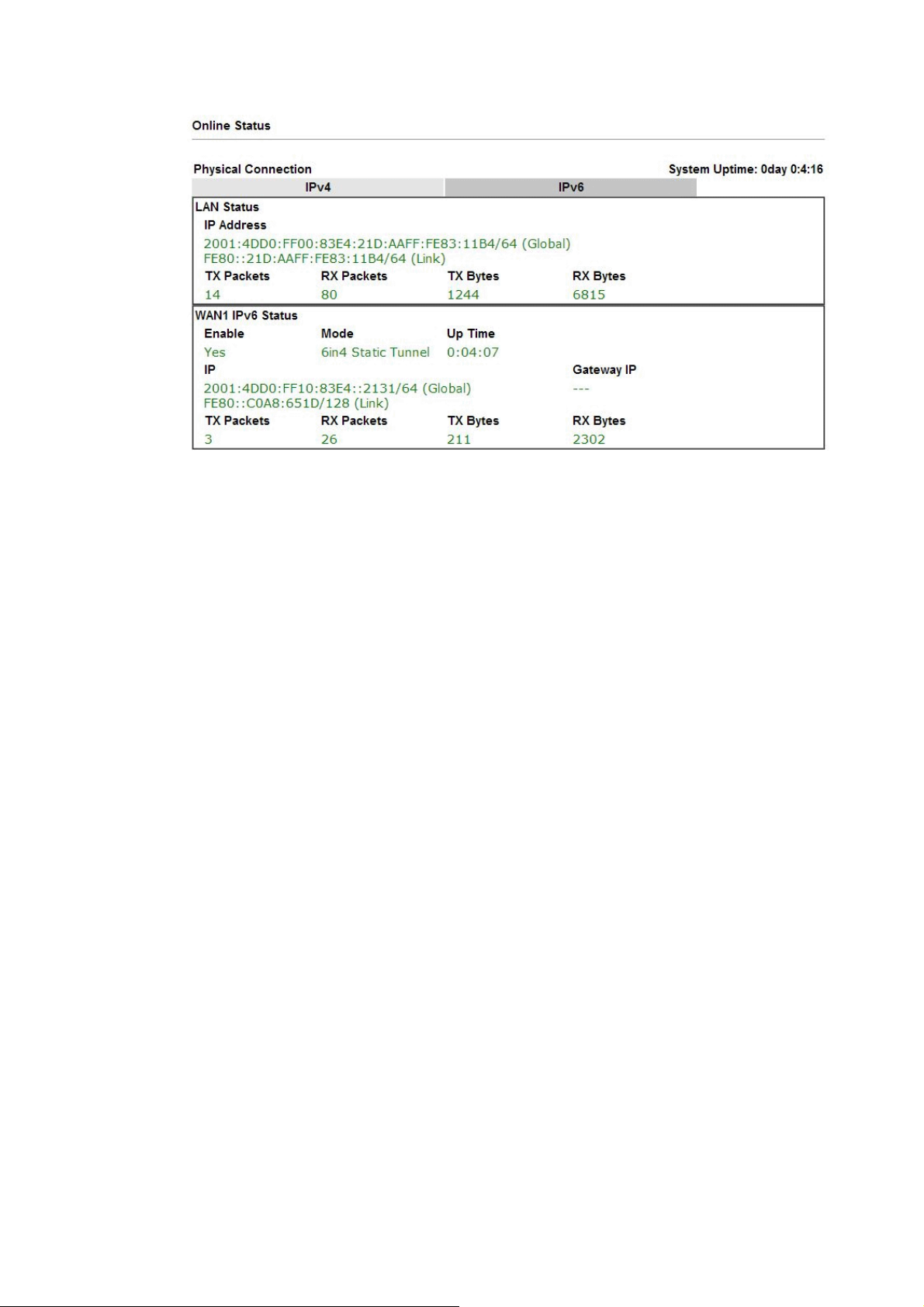
88
Vigor2762 Series User’s Guide
 Loading...