

Page 1
i
Vigor2710 Series User’s Guide
Page 2

Vigor2710 Series User’s Guide
ii
Page 3

Vigor2710 Series
ADSL2/2+ Firewall Router
User’s Guide
Version: 3.0
Firmware Version: V3.6.3
Date: 12/12/2012
iii
Vigor2710 Series User’s Guide
Page 4

Copyright Information
Copyright
Declarations
Trademarks
Copyright 2012 All rights reserved. This publication contains information that is
protected by copyright. No part may be reproduced, transmitted, transcribed, stored in a
retrieval system, or translated into any language without written permission from the
copyright holders.
The following trademarks are used in this document:
z Microsoft is a registered trademark of Microsoft Corp.
z Windows, Windows 95, 98, Me, NT, 2000, XP, Vista and Explorer are
trademarks of Microsoft Corp.
z Apple and Mac OS are registered trademarks of Apple Inc.
z Other products may be trademarks or registered trademarks of their respective
manufacturers.
Safety Instructions and Approval
Safety
Instructions
Warranty
z Read the installation guide thoroughly before you set up the router.
z The router is a complicated electronic unit that may be repaired only be
authorized and qualified personnel. Do not try to open or repair the router
yourself.
z Do not place the router in a damp or humid place, e.g. a bathroom.
z The router should be used in a sheltered area, within a temperature range of +5 to
+40 Celsius.
z Do not expose the router to direct sunlight or other heat sources. The housing and
electronic components may be damaged by direct sunlight or heat sources.
z Do not deploy the cable for LAN connection outdoor to prevent electronic shock
hazards.
z Keep the package out of reach of children.
z When you want to dispose of the router, please follow local regulations on
conservation of the environment.
We warrant to the original end user (purchaser) that the router will be free from any
defects in workmanship or materials for a period of two (2) years from the date of
purchase from the dealer. Please keep your purchase receipt in a safe place as it serves
as proof of date of purchase. During the warranty period, and upon proof of purchase,
should the product have indications of failure due to faulty workmanship and/or
materials, we will, at our discretion, repair or replace the defective products or
components, without charge for either parts or labor, to whatever extent we deem
necessary tore-store the product to proper operating condition. Any replacement will
consist of a new or re-manufactured functionally equivalent product of equal value, and
will be offered solely at our discretion. This warranty will not apply if the product is
modified, misused, tampered with, damaged by an act of God, or subjected to abnormal
working conditions. The warranty does not cover the bundled or licensed software of
other vendors. Defects which do not significantly affect the usability of the product will
not be covered by the warranty. We reserve the right to revise the manual and online
documentation and to make changes from time to time in the contents hereof without
obligation to notify any person of such revision or changes.
Be a Registered
Owner
Firmware & Tools
Updates
Vigor2710 Series User’s Guide
Web registration is preferred. You can register your Vigor router via
http://www.draytek.com.
Due to the continuous evolution of DrayTek technology, all routers will be regularly
upgraded. Please consult the DrayTek web site for more information on newest
firmware, tools and documents.
http://www.draytek.com
iv
Page 5

European Community Declarations
Manufacturer: DrayTek Corp.
Address: No. 26, Fu Shing Road, HuKou Township, HsinChu Industrial Park, Hsin-Chu, Taiwan 303
Product: Vigor2710 Series Router
DrayTek Corp. declares that Vigor2710 Series of routers are in compliance with the following essential
requirements and other relevant provisions of R&TTE Directive 1999/5/EEC.
The product conforms to the requirements of Electro-Magnetic Compatibility (EMC) Directive 2004/108/EC by
complying with the requirements set forth in EN55022/Class B and EN55024/Class B.
The product conforms to the requirements of Low Voltage (LVD) Directive 2006/95/EC by complying with the
requirements set forth in EN60950-1.
Regulatory Information
Federal Communication Commission Interference Statement
This equipment has been tested and found to comply with the limits for a Class B digital device, pursuant to Part
15 of the FCC Rules. These limits are designed to provide reasonable protection against harmful interference in a
residential installation. This equipment generates, uses and can radiate radio frequency energy and, if not installed
and used in accordance with the instructions, may cause harmful interference to radio communications. However,
there is no guarantee that interference will not occur in a particular installation. If this equipment does cause
harmful interference to radio or television reception, which can be determined by turning the equipment off and
on, the user is encouraged to try to correct the interference by one of the following measures:
z Reorient or relocate the receiving antenna.
z Increase the separation between the equipment and receiver.
z Connect the equipment into an outlet on a circuit different from that to which the receiver is connected.
z Consult the dealer or an experienced radio/TV technician for help.
This device complies with Part 15 of the FCC Rules. Operation is subject to the following two conditions:
(1) This device may not cause harmful interference, and
(2) This device may accept any interference received, including interference that may cause undesired operation.
Please visit http://www.draytek.com/user/SupportDLRTTECE.php
This product is designed for the DSL, POTS, DECT and 2.4GHz WLAN network throughout the EC region and
Switzerland with restrictions in France. Please see the user manual for the applicable networks on your product.
v
Vigor2710 Series User’s Guide
Page 6

Vigor2710 Series User’s Guide
vi
Page 7

TTaabbllee ooff CCoonntteennttss
Introduction ..................................................................................................1
1.1 Web Configuration Buttons Explanation................................................................................. 1
1.2 LED Indicators and Connectors.............................................................................................. 2
1.2.1 For Vigor2710................................................................................................................... 2
1.2.2 For Vigor2710n................................................................................................................. 4
1.2.3 For Vigor2710Vn............................................................................................................... 6
1.2.4 For Vigor2710VDn............................................................................................................ 8
1.3 Hardware Installation ............................................................................................................10
1.4 Printer Installation ..................................................................................................................11
Initial Configuration...................................................................................17
2.1 Accessing the Web User Interface........................................................................................ 17
2.2 Changing Password.............................................................................................................. 19
2.3 Quick Start Wizard................................................................................................................ 20
2.3.1 Adjusting Protocol/Encapsulation................................................................................... 20
2.3.2 PPPoE/PPPoA................................................................................................................ 22
2.3.3 1483 Bridged IP.............................................................................................................. 23
2.3.4 1483 Routed IP............................................................................................................... 25
2.4 Service Activation Wizard...................................................................................................... 26
2.5 VoIP Wizard........................................................................................................................... 29
2.6 Online St atus......................................................................................................................... 30
2.6.1 Physical Connection.......................................................................................................30
2.6.2 Virtual WAN.................................................................................................................... 32
2.7 Saving Configuration............................................................................................................. 33
2.8 Registering Vigor Router....................................................................................................... 33
Application and Example...........................................................................37
3.1 How to configure settings for IPv6 Service........................................................................... 37
3.2 How Can I Use FTP to Get the Files from USB Storage Device Connecting to Vigor Router?
.................................................................................................................................................... 47
3.3 How to Customize Your Login Page ..................................................................................... 50
3.4 Create a LAN-to-LAN Connection Between Remote Office and Headquarter..................... 51
3.5 Create a Remote Dial-in User Connection Between the Teleworker and Headquarter........ 58
3.6 LAN – Created by Using NAT ............................................................................................... 63
3.7 Calling Scenario for VoIP function ........................................................................................ 65
vii
Vigor2710 Series User’s Guide
Page 8

3.7.1 Calling via SIP Sever...................................................................................................... 65
3.7.2 Peer-to-Peer Calling....................................................................................................... 67
3.8 Request a certificate from a CA server on Windows CA Server........................................... 69
3.9 Request a CA Certificate and Set as Trusted on Windows CA Server................................. 73
3.10 Creating an Account for MyVigor........................................................................................ 75
3.10.1 Creating an Account via Vigor Router.......................................................................... 75
3.10.2 Creating an Account via MyVigor Web Site.................................................................. 79
Advanced Configuration............................................................................83
4.1 Internet Access...................................................................................................................... 83
4.1.1 Basics of Internet Protocol (IP) Network......................................................................... 83
4.1.2 PPPoE/PPPoA................................................................................................................ 84
4.1.3 MPoA.............................................................................................................................. 90
4.1.4 IPv6................................................................................................................................. 94
4.1.5 Multi-PVCs...................................................................................................................... 98
4.2 LAN ..................................................................................................................................... 105
4.2.1 Basics of LAN ............................................................................................................... 105
4.2.2 General Setup............................................................................................................... 107
4.2.3 Static Route.................................................................................................................. 112
4.2.4 VLAN............................................................................................................................. 116
4.2.5 Bind IP to MAC............................................................................................................. 117
4.3 NAT ......................................................................................................................................118
4.3.1 Port Redirection............................................................................................................ 119
4.3.2 DMZ Host...................................................................................................................... 123
4.3.3 Open Ports.................................................................................................................... 126
4.3.4 Address Mapping.......................................................................................................... 128
4.4 Firewall................................................................................................................................ 130
4.4.1 Basics for Firewall......................................................................................................... 130
4.4.2 General Setup............................................................................................................... 132
4.4.3 Filter Setup ................................................................................................................... 136
4.4.4 DoS Defense ................................................................................................................ 144
4.5 Objects Settings..................................................................................................................148
4.5.1 IP Object....................................................................................................................... 148
4.5.2 IP Group ....................................................................................................................... 151
4.5.3 IPv6 Object................................................................................................................... 153
4.5.4 IPv6 Group.................................................................................................................... 155
4.5.5 Service Type Object ..................................................................................................... 157
4.5.6 Service Type Group...................................................................................................... 159
4.5.7 Keyword Object ............................................................................................................161
4.5.8 Keyword Group............................................................................................................. 163
4.5.9 File Extension Object.................................................................................................... 165
4.6 CSM .................................................................................................................................... 167
4.6.1 APP Enforcement Profile.............................................................................................. 168
4.6.2 URL Content Filter Profile............................................................................................. 170
4.6.3 Web Content Filter Profile............................................................................................. 174
4.7 Bandwidth Management ..................................................................................................... 178
4.7.1 Sessions Limit............................................................................................................... 178
Vigor2710 Series User’s Guide
viii
Page 9

4.7.2 Bandwidth Limit ............................................................................................................180
4.7.3 Quality of Service.......................................................................................................... 182
4.7.4 APP QoS ...................................................................................................................... 191
4.8 Applications.........................................................................................................................192
4.8.1 Dynamic DNS............................................................................................................... 192
4.8.2 Schedule....................................................................................................................... 195
4.8.3 RADIUS........................................................................................................................ 197
4.8.4 UPnP............................................................................................................................. 198
4.8.5 IGMP............................................................................................................................. 200
4.8.6 Wake on LAN................................................................................................................ 201
4.9 VPN and Remote Access.................................................................................................... 202
4.9.1 Remote Access Control................................................................................................ 202
4.9.2 PPP General Setup ...................................................................................................... 203
4.9.3 IPSec General Setup.................................................................................................... 204
4.9.4 IPSec Peer Identity....................................................................................................... 206
4.9.5 Remote Dial-in User ..................................................................................................... 208
4.9.6 LAN to LAN................................................................................................................... 211
4.9.7 Connection Management.............................................................................................. 220
4.10 Certificate Management.................................................................................................... 221
4.10.1 Local Certificate.......................................................................................................... 221
4.10.2 Trusted CA Certificate ................................................................................................ 223
4.10.3 Certificate Backup....................................................................................................... 224
4.11 VoIP................................................................................................................................... 224
4.11.1 DialPlan ...................................................................................................................... 226
4.11.2 SIP Accounts.............................................................................................................. 236
4.11.3 Phone Settings ...........................................................................................................242
4.11.4 DECT.......................................................................................................................... 248
4.11.5 Status.......................................................................................................................... 252
4.12 Wireless LAN .................................................................................................................... 254
4.12.1 Basic Concepts........................................................................................................... 254
4.12.2 General Setup............................................................................................................. 256
4.12.3 Security....................................................................................................................... 259
4.12.4 Access Control............................................................................................................ 261
4.12.5 WPS............................................................................................................................ 262
4.12.6 WDS............................................................................................................................ 265
4.12.7 Advanced Setting........................................................................................................ 268
4.12.8 WMM Configuration.................................................................................................... 269
4.12.9 AP Discovery.............................................................................................................. 271
4.12.10 Station List................................................................................................................272
4.13 USB Application................................................................................................................ 273
4.13.1 USB General Settings................................................................................................. 273
4.13.2 USB User Management.............................................................................................. 274
4.13.3 File Explorer................................................................................................................ 277
4.13.4 USB Disk Status......................................................................................................... 278
4.14 System Maintenance......................................................................................................... 279
4.14.1 System Status............................................................................................................. 279
4.14.2 TR-069........................................................................................................................ 281
4.14.3 Administrator Password.............................................................................................. 282
4.14.4 User Password ........................................................................................................... 283
4.14.5 Login Page Greeting................................................................................................... 285
4.14.6 Configuration Backup ................................................................................................. 287
4.14.7 Syslog/Mail Alert.........................................................................................................289
4.14.8 Time and Date............................................................................................................ 291
ix
Vigor2710 Series User’s Guide
Page 10

4.14.9 Management............................................................................................................... 292
4.14.10 Reboot System......................................................................................................... 294
4.14.11 Firmware Upgrade.................................................................................................... 295
4.14.12 Activation.................................................................................................................. 296
4.15 Diagnostics........................................................................................................................ 298
4.15.1 Dial-out Triggering...................................................................................................... 298
4.15.2 Routing Table ............................................................................................................. 299
4.15.3 ARP Cache Table....................................................................................................... 300
4.15.4 IPv6 Neighbour Table................................................................................................. 300
4.15.5 DHCP Table................................................................................................................ 301
4.15.6 NAT Sessions Table................................................................................................... 302
4.15.7 Data Flow Monitor....................................................................................................... 303
4.15.8 Traffic Graph............................................................................................................... 305
4.15.9 Ping Diagnosis............................................................................................................ 306
4.15.10 Trace Route.............................................................................................................. 307
4.16 Product Registration.......................................................................................................... 308
Trouble Shooting......................................................................................309
5.1 Checking If the Hardware Status Is OK or Not....................................................................309
5.2 Checking If the Network Connection Settings on Your Computer Is OK or Not ................. 310
5.3 Pinging the Router from Your Computer............................................................................. 312
5.4 Checking If the ISP Settings are OK or Not........................................................................ 313
5.5 Problems for 3G Network Connection ................................................................................ 314
5.6 Backing to Factory Default Setting If Necessary ................................................................ 314
5.7 Contacting Your Dealer....................................................................................................... 315
Vigor2710 Series User’s Guide
x
Page 11
IInnttrroodduuccttiioonn
Vigor2710 series is an ADSL router. It integrates IP layer QoS, NAT session/bandwidth
management to help users control works well with large bandwidth.
By adopting hardware-based VPN platform and hardware encryption of AES/DES/3DS, the
router increases the performance of VPN greatly, and offers several protocols (such as
IPSec/PPTP/L2TP) with up to 2 VPN tunnels.
The object-based design used in SPI (Stateful Packet Inspection) firewall allows users to set
firewall policy with ease. CSM (Content Security Management) provides users control and
management in IM (Instant Messenger) and P2P (Peer to Peer) more efficiency than before.
By the way, DoS/DDoS prevention and URL/Web content filter strengthen the security
outside and control inside.
Object-based firewall is flexible and allows your network be safe. In addition, through VoIP
function, the communication fee for you and remote people can be reduced.
In addition, Vigor2710 series supports USB interface for connecting USB printer to share
printer or USB storage device for sharing files. Vigor2710 series provides two-level
management to simplify the configuration of network connection. The user operation allows
user accessing into WEB interface via simple configuration. However, if users want to have
advanced configurations, they can access into WEB interface through administration
operation.
11..11 WWeebb CCoonnffiigguurraattiioonn BBuuttttoonnss EExxppllaannaattiioonn
Several main buttons appeared on the web pages are defined as the following:
Save and apply current settings.
Cancel current settings and recover to the previous saved settings.
Clear all the selections and parameters settings, including selection from
drop-down list. All the values must be reset with factory default settings.
Add new settings for specified item.
Edit the settings for the selected item.
Delete the selected item with the corresponding settings.
Note: For the other buttons shown on the web pages, please refer to Chapter 4 for detailed
explanation.
1
Vigor2710 Series User’s Guide
Page 12

11..22 LLEEDD IInnddiiccaattoorrss aanndd CCoonnnneeccttoorrss
Before you use the Vigor router, please get acquainted with the LED indicators and
connectors first.
11..22..11 FFoorr VViiggoorr22771100
LED Status Explanation
ACT
(Activity)
CSM On The profile(s) of CSM (Content Security
DSL
LAN 1/2/3/4
VPN On The VPN tunnel is active.
QoS
WCF On The profile(s) of CSM (Content Security
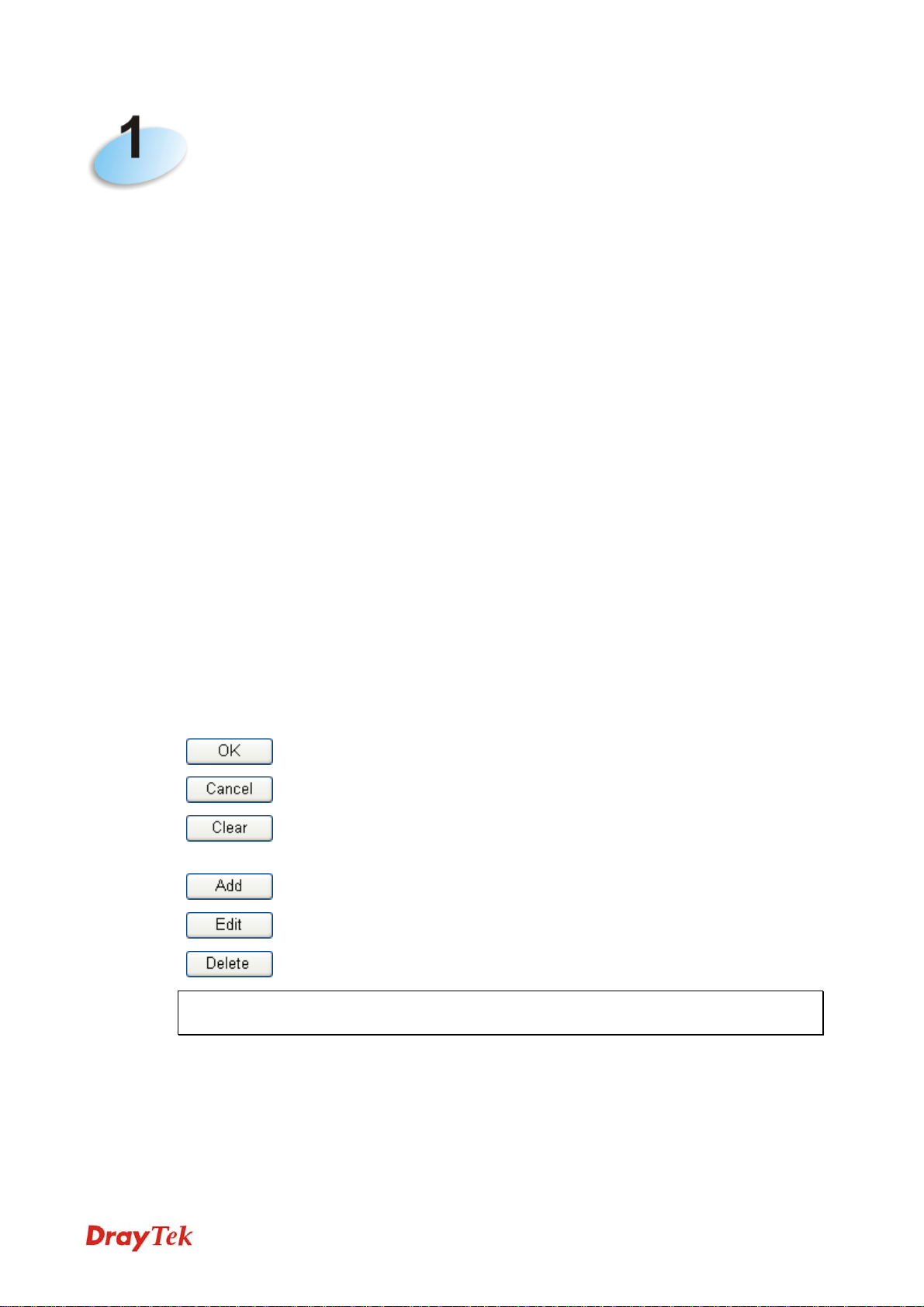
Interface Description
DSL Connecter for accessing the Internet through ADSL2/2+.
LAN (1-4) Connecters for local networked devices.
USB Connecter for USB storage device (Pen Driver/Mobile
Blinking The router is powered on and running
Off The router is powered off.
On The router is ready to access Internet
Blinking Slowly: The modem is ready.
On The port is connected.
Off The port is disconnected.
Blinking The data is transmitting.
On A USB device is connected and active. USB
Blinking The data is transmitting.
On The QoS function is active.
On The DoS/DDoS function is active. DoS
Blinking It will blink while detecting an attack.
HD) or printer.
normally.
Management) for IM/P2P, URL/Web
Content Filter application can be enabled
from Firewall >>General Setup. (Such
profile must be established under CSM
menu).
through DSL link.
Quickly: The connection is training.
Management) for Web Content Filter
application can be enabled from Firewall
>>General Setup. (Such profile must be
established under CSM menu)
Vigor2710 Series User’s Guide
2
Page 13

Interface Description
Factory Reset Restore the default settings. Usage: Turn on the router (ACT LED is blinking). Press the
hole and keep for more than 5 seconds. When you see the ACT LED begins to blink
rapidly than usual, release the button. Then the router will restart with the factory default
configuration.
PWR Connecter for a power adapter.
ON/OFF
Power Switch.
3
Vigor2710 Series User’s Guide
Page 14

11..22..22 FFoorr VViiggoorr22771100nn
LED Status Explanation
ACT
(Activity)
DSL
LAN 1/2/3/4
VPN On The VPN tunnel is active.
QoS
WPS
WPS Button
Interface Description
WLAN
DSL Connecter for accessing the Internet through ADSL2/2+.
LAN (1-4) Connecters for local networked devices.
USB Connecter for USB storage (Pen Driver Mobile/HD) or
Blinking The router is powered on and running
normally.
Off The router is powered off.
On Wireless access point is ready. WLAN
Blinking It will blink while wireless traffic goes
through.
On The router is ready to access Internet
through DSL link.
Blinking Slowly: The modem is ready.
Quickly: The connection is training.
On The port is connected.
Off The port is disconnected.
Blinking The data is transmitting.
On A USB device is connected and active. USB
Blinking The data is transmitting.
On The QoS function is active.
On The DoS/DDoS function is active. DoS
Blinking It will blink while detecting an attack.
On The WPS is on.
Off The WPS is off.
Blinking Waiting for wireless client sending requests
for connection about two minutes.
On Press this button for 2 seconds to wait for
client device making network connection
through WPS. When the LED lights up, the
WPS will be on.
Off The WPS is off.
Blinking Waiting for wireless client sending requests
for connection about 2 minutes.
Press the button once to enable (WLAN LED on) or
disable (WLAN LED off) wireless connection.
printer.
Vigor2710 Series User’s Guide
4
Page 15

Interface Description
Factory Reset Restore the default settings. Usage: Turn on the router (ACT LED is blinking). Press the
hole and keep for more than 5 seconds. When you see the ACT LED begins to blink
rapidly than usual, release the button. Then the router will restart with the factory default
configuration.
PWR Connecter for a power adapter.
ON/OFF
Power Switch.
5
Vigor2710 Series User’s Guide
Page 16

11..22..33 FFoorr VViiggoorr22771100VVnn
LED Status Explanation
ACT
(Activity)
DSL
LAN 1/2/3/4
Phone1/
Phone2
Line
WPS
WPS Button
Interface Description
WLAN
DSL Connecter for accessing the Internet through ADSL2/2+.
LAN (1-4) Connecters for local networked devices.
USB Connecter for USB storage (Pen Driver Mobile/HD) or
Blinking The router is powered on and running
normally.
Off The router is powered off.
On Wireless access point is ready. WLAN
Blinking It will blink while wireless traffic goes
through.
On The router is ready to access Internet
through DSL link.
Blinking Slowly: The modem is ready.
Quickly: The connection is training.
On The port is connected.
Off The port is disconnected.
Blinking The data is transmitting.
On A USB device is connected and active. USB
Blinking The data is transmitting.
On The phone connected to this port is off-hook.
Off The phone connected to this port is on-hook.
Blinking A phone call comes.
On A PSTN phone call comes (in and out).
However, when the phone call is
disconnected, the LED will be off about six
seconds later.
Off There is no PSTN phone call.
On The WPS is on.
Off The WPS is off.
Blinking Waiting for wireless client sending requests
for connection about two minutes.
On Press this button for 2 seconds to wait for
client device making network connection
through WPS. When the LED lights up, the
WPS will be on.
Off The WPS is off.
Blinking Waiting for wireless client sending requests
for connection about 2 minutes.
Press the button once to enable (WLAN LED on) or
disable (WLAN LED off) wireless connection.
printer.
Vigor2710 Series User’s Guide
6
Page 17

Interface Description
Line Connector of analog phone for PSTN life line.
Phone2/Phone1
Factory Reset Restore the default settings. Usage: Turn on the router (ACT LED is blinking). Press the
PWR Connecter for a power adapter.
ON/OFF
Connecter of analog phone for VoIP communication
hole and keep for more than 5 seconds. When you see the ACT LED begins to blink
rapidly than usual, release the button. Then the router will restart with the factory default
configuration.
Power Switch.
.
7
Vigor2710 Series User’s Guide
Page 18

11..22..44 FFoorr VViiggoorr22771100VVDDnn
LED Status Explanation
ACT
(Activity)
DSL
LAN
1/2/3/4
DECT
Phone
Line
WPS
DECT
Pairing/Pag
ing / WPS
Button
Blinking The router is powered on and running
normally.
Off The router is powered off.
On Wireless access point is ready. WLAN
Blinking It will blink while wireless traffic goes
through.
On The router is ready to access Internet
through DSL link.
Blinking Slowly: The modem is ready.
Quickly: The connection is training.
On The port is connected.
Off The port is disconnected.
Blinking The data is transmitting.
On A USB device is connected and active. USB
Blinking The data is transmitting.
On DECT phone is in use
Off DECT phone is idle or off.
Blinking A DECT phone call comes.
On The phone connected to this port is
off-hook.
Off The phone connected to this port is
on-hook.
Blinking A phone call comes.
On A PSTN phone call comes (in and out).
However, when the phone call is
disconnected, the LED will be off about
six seconds later.
Off There is no PSTN phone call.
On The WPS is on.
Off The WPS is off.
Blinking Waiting for wireless client sending
requests for connection or DECT
handset about two minutes.
On
DECT Pairing and WPS: Press and
hold the button for more than 2
seconds then you could try to register
DECT phone with 2710 within 2
minutes.
DECT Paging: Press once. All handsets
will have beep sound, press the button
again or press any key on any handset
will stop the beep sound.
Off The WPS is off.
Blinking Waiting for wireless client sending
requests for connection about 2 minutes.
Vigor2710 Series User’s Guide
8
Page 19
Interface Description
WLAN
DSL Connector for accessing the Internet through ADSL2/2+.
LAN (1-4) Connectors for local networked devices.
USB Connector for USB storage (Pen Driver/Mobile HD) or
Press the button once to enable (WLAN LED on) or
disable (WLAN LED off) wireless connection.
printer.
Interface Description
Line Connector for PSTN life line.
Phone
Factory Reset Restore the default settings. Usage: Turn on the router (ACT LED is blinking). Press the
PWR Connector for a power adapter.
ON/OFF
Connector of analog phone for VoIP communication
hole and keep for more than 5 seconds. When you see the ACT LED begins to blink
rapidly than usual, release the button. Then the router will restart with the factory default
configuration.
Power Switch.
.
9
Vigor2710 Series User’s Guide
Page 20
11..33 HHaarrddwwaarree IInnssttaallllaattiioonn
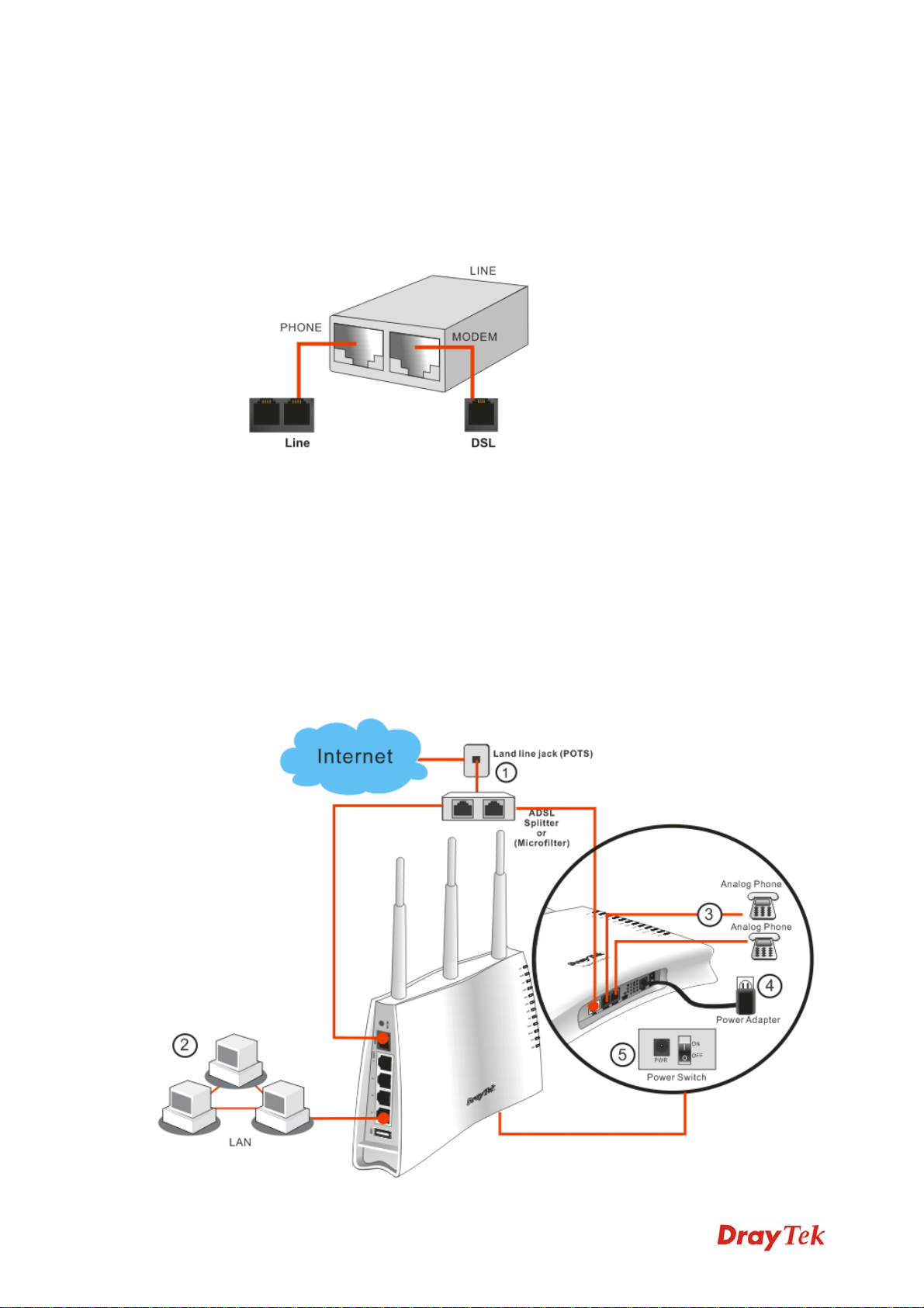
Before starting to configure the router, you have to connect your devices correctly.
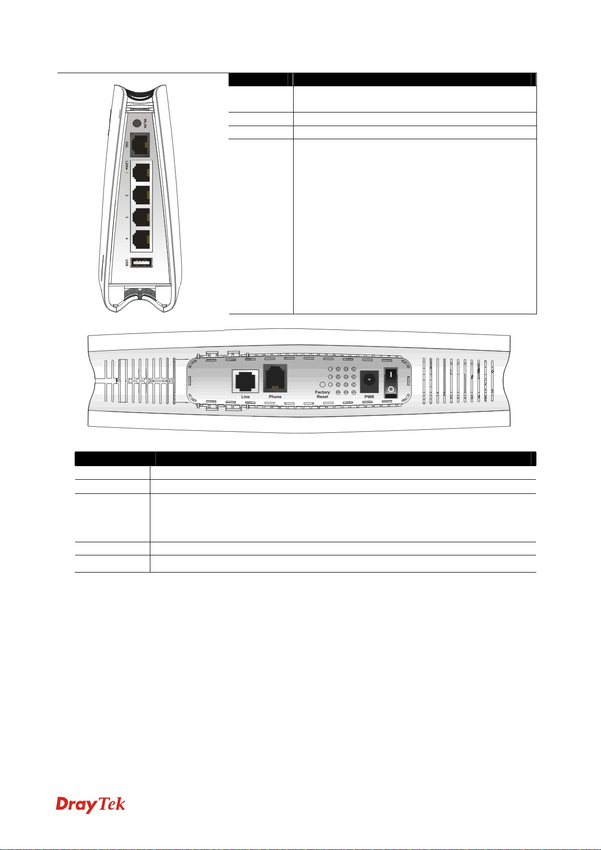
1. Connect the ADSL interface to the external ADSL splitter with an ADSL line cable for
all models. For Vigor2710Vn/VDn, also connect Line interface to external ADSL
splitter.
2. Connect one end of an Ethernet cable (RJ-45) to one of the LAN ports of the router and
the other end of the cable (RJ-45) into the Ethernet port on your computer.
3. Connect the telephone sets with phone lines (for using VoIP function). For the model
without phone ports, skip this step.
4. Connect one end of the power adapter to the router’s power port on the rear panel, and
the other side into a wall outlet.
5. Power on the device by pressing down the power switch on the rear panel.
6. The system starts to initiate. After completing the system test, the ACT LED will light
up and start blinking.
Here, we take Annex A model as an example for describing hardware installation.
Vigor2710 Series User’s Guide
10
Page 21
Caution:
1. Each of the Phone ports can be connected to an analog phone only. Do not connect
the phone ports to the land line jack. Such connection might damage your router.
2. When the power is shutdown, VoIP phone will be disconnected. However, a phone
set connected to Phone 2 port can be used as the traditional telephone for the line will
be guided to land line jack via the router (loop through).
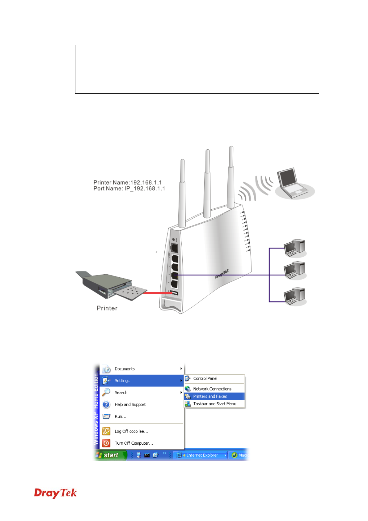
11..44 PPrriinntteerr IInnssttaallllaattiioonn
You can install a printer onto the router for sharing printing. All the PCs connected this
router can print documents via the router. The example provided here is made based on
Windows XP/2000. For Windows 98/SE/Vista, please visit www.draytek.com.
Before using it, please follow the steps below to configure settings for connected computers
(or wireless clients).
1. Connect the printer with the router through USB/parallel port.
2. Open Start->Settings-> Printer and Faxes.
3. Open File->Add a New Computer. A welcome dialog will appear. Please click Next.
11
Vigor2710 Series User’s Guide
Page 22
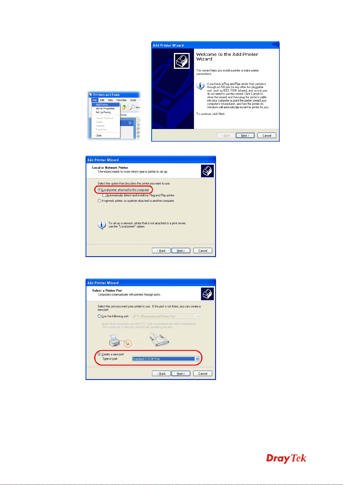
4. Click Local printer attached to this computer and click Next.
5. In this dialog, choose Create a new port Type of port and use the drop down list to
select Standard TCP/IP Port. Click Next.
Vigor2710 Series User’s Guide
12
Page 23
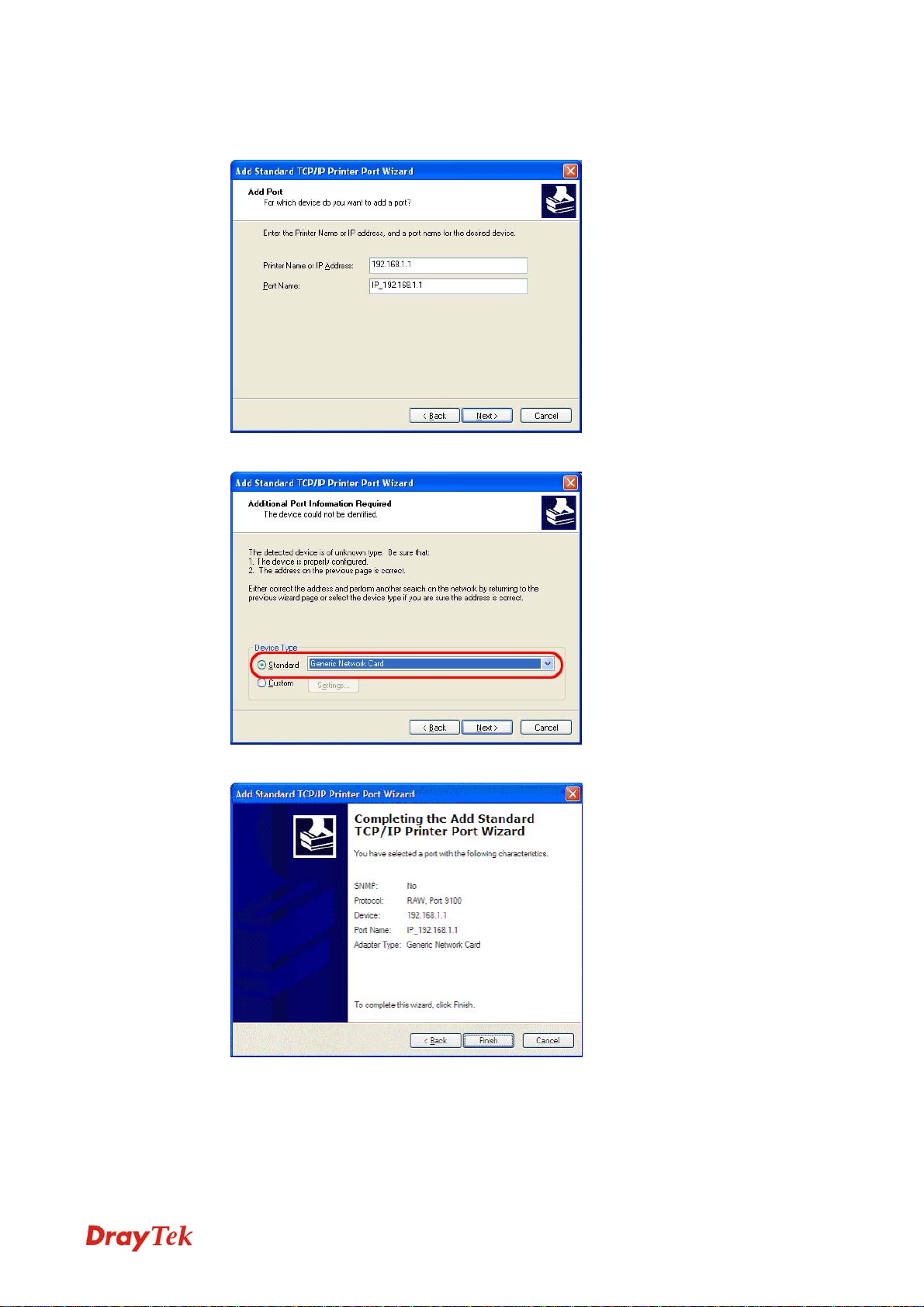
6. In the following dialog, type 192.168.1.1 (router’s LAN IP) in the field of Printer
Name or IP Address and type IP_192.168.1.1 as the port name. Then, click Next.
7. Click Standard and choose Generic Network Card.
8. Then, in the following dialog, click Finish.
13
Vigor2710 Series User’s Guide
Page 24
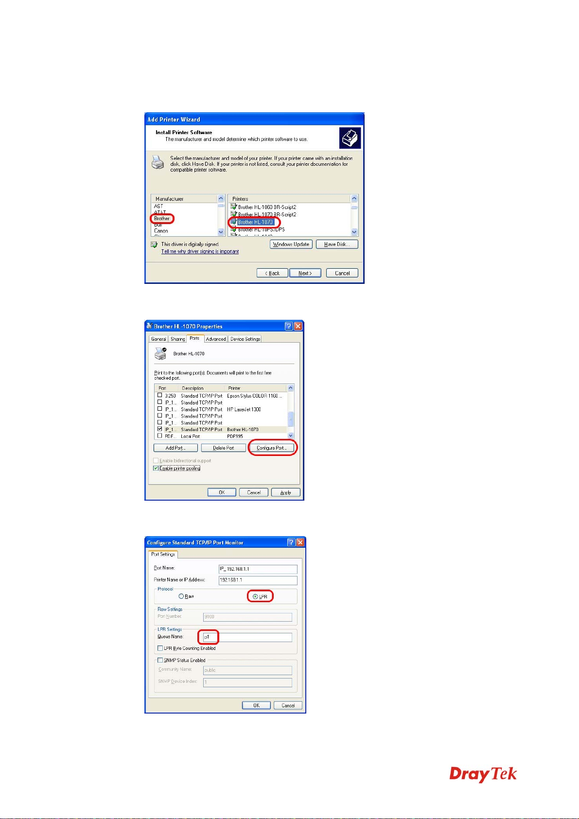
9. Now, your system will ask you to choose right name of the printer that you installed
onto the router. Such step can make correct driver loaded onto your PC. When you
finish the selection, click Next.
10. For the final stage, you need to go back to Control Panel-> Printers and edit the
property of the new printer you have added.
11. Select "LPR" on Protocol, type p1 (number 1) as Queue Name. Then click OK. Next
please refer to the red rectangle for choosing the correct protocol and LPR name.
Vigor2710 Series User’s Guide
14
Page 25
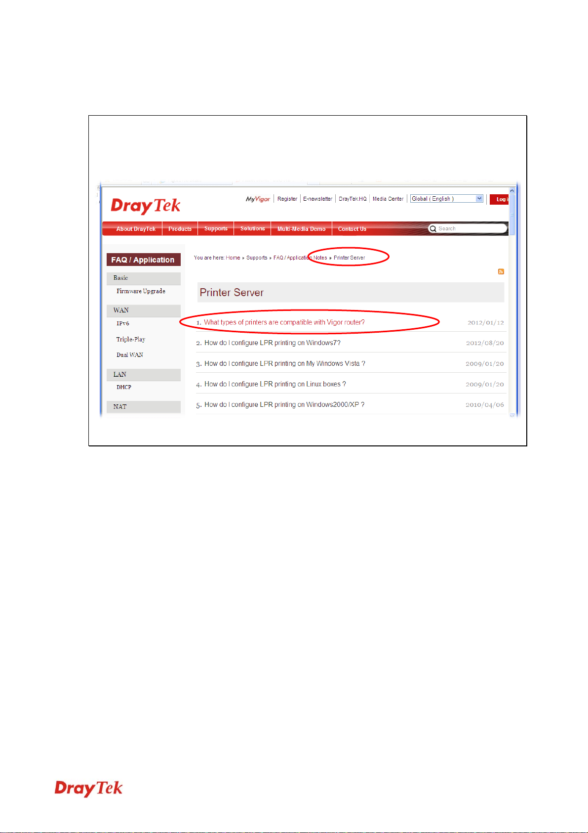
The printer can be used for printing now. Most of the printers with different manufacturers
are compatible with vigor router.
Note 1: Some printers with the fax/scanning or other additional functions are not supported. If you
do not know whether your printer is supported or not, please visit www.draytek.com to find out
the printer list. Open Support >FAQ/Application Notes; find out the link of Printer Server and
click it; then click the What types of printers are compatible with Vigor router? link.
Note 2: Vigor router supports printing request from computers via LAN ports but not WAN port.
15
Vigor2710 Series User’s Guide
Page 26

This page is left blank.
Vigor2710 Series User’s Guide
16
Page 27
IInniittiiaall C
For using the router properly, it is necessary for you to change the password of web
configuration for security and adjust primary basic settings.
This chapter explains how to setup a password for accessing into the web configurator of
Vigor router and how to adjust settings for accessing Internet successfully..
Coonnffiigguurraattiioonn
22..11 AAcccceessssiinngg tthhee WWeebb UUsseerr IInntteerrffaaccee
1. Make sure your PC connects to the router correctly.
Notice: You may either simply set up your computer to get IP dynamically from
the router or set up the IP address of the computer to be the same subnet as the
default IP address of Vigor router 192.168.1.1. For the detailed information,
please refer to the later section - Trouble Shooting of the guide.
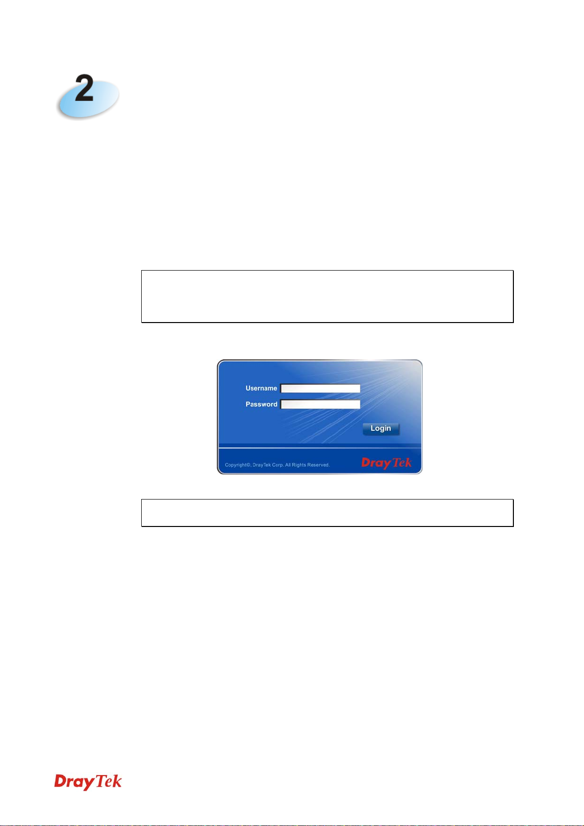
2. Open a web browser on your PC and type http://192.168.1.1. The following window
will be open to ask for username and password.
3. Please type “admin/admin” as the Username/Password and click Login.
Note: If you fail to access to the web configuration, please go to “Trouble
Shooting” for detecting and solving your problem.
17
Vigor2710 Series User’s Guide
Page 28
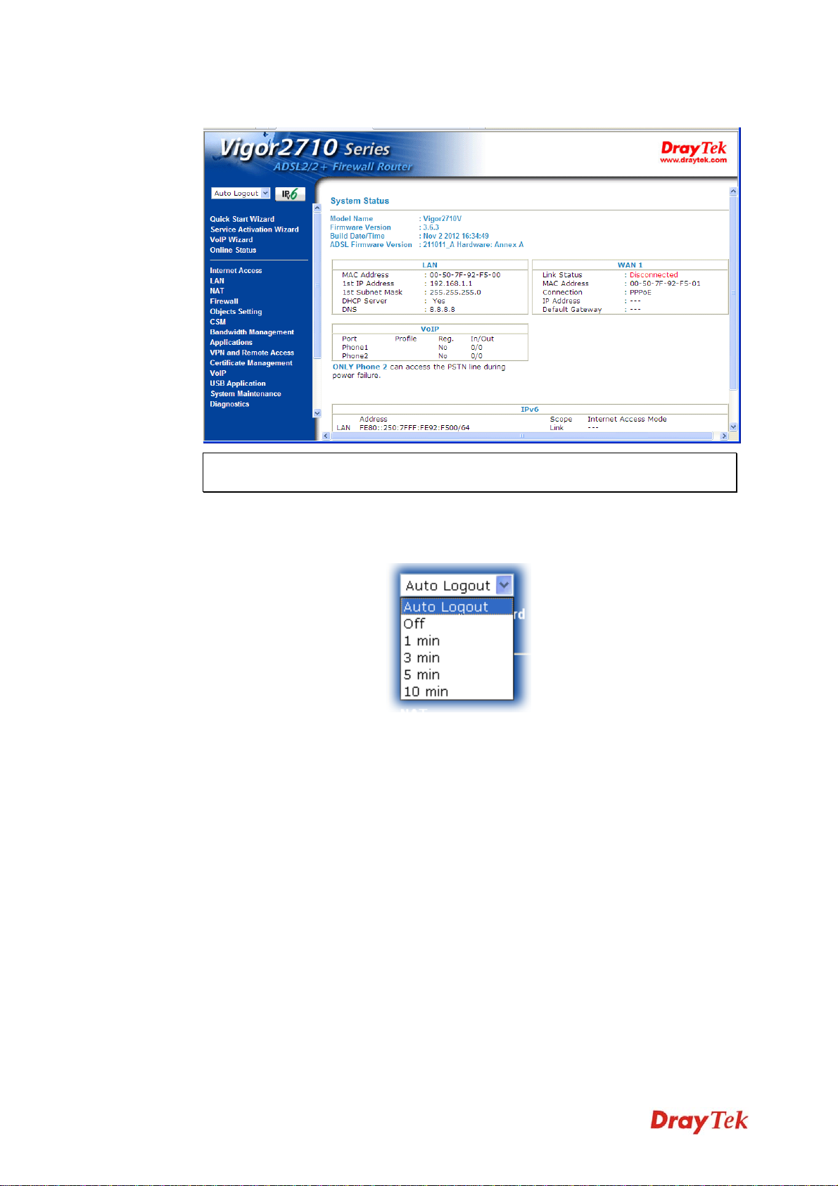
4. Now, the Main Screen will appear.
Note: The home page will be different slightly in accordance with the type of the
router you have.
5. The web page can be logged out according to the chosen condition. The default setting
is Auto Logout, which means the web configuration system will logout after 5 minutes
without any operation. Change the setting for your necessity.
Vigor2710 Series User’s Guide
18
Page 29
22..22 CChhaannggiinngg PPaasssswwoorrdd
Please change the password for the original security of the router.
1. Open a web browser on your PC and type http://192.168.1.1. A pop-up window will
open to ask for username and password.
2. Please type “admin/admin” as the Username/Password and click Login.
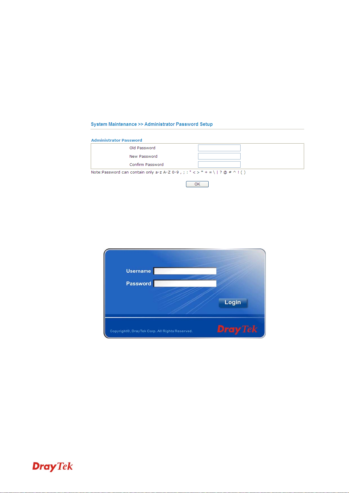
3. Go to System Maintenance page and choose Administrator Password/User
Password.
4. Enter the login password (the default is admin) on the field of Old Password. Type the
new password in New Password and Confirm Password fields. Then click OK to
continue.
5. Now, the password has been changed. Next time, use the new password to access the
Web Configurator for this router.
19
Vigor2710 Series User’s Guide
Page 30
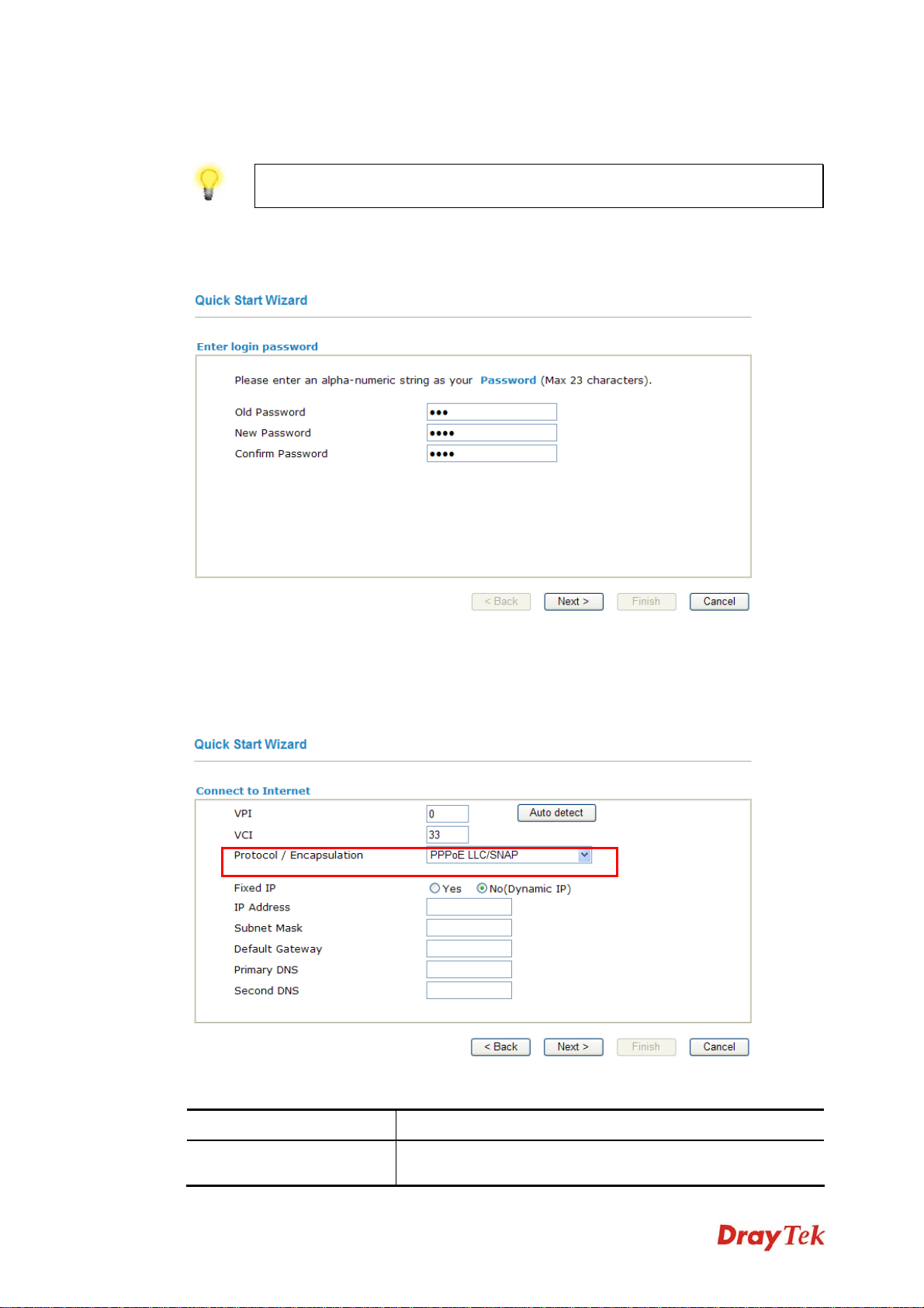
22..33 QQuuiicckk SSttaarrtt WWiizzaarrdd
Notice: Quick Start Wizard for user operation is the same as for administrator’s
operation.
If your router can be under an environment with high speed NAT, the configuration provide
here can help you to deploy and use the router quickly. The first screen of Quick Start
Wizard is entering login password. After typing the password, please click Next.
22..33..11 AAddjjuussttiinngg PPrroottooccooll//EEnnccaappssuullaattiioonn
In the Quick Start Wizard, you can configure the router to access the Internet with different protocol/modes such as PPPoE, PPPoA, Bridged IP, or Routed IP. The router supports the
ADSL WAN interface for Internet access.
Available settings are explained as follows:
Item Description
VPI
Vigor2710 Series User’s Guide
Stands for Virtual Path Identifier. It is an 8-bit
header inside each ATM cell that indicates where the cell
20
Page 31

should be routed. The ATM, is a method of sending data in
small packets of fixed sizes. It is used for transferring data
to client computers.
VCI
Protocol/Encapsulation
Fixed IP
IP Address
Stands for Virtual Channel Identifier. It is a 16-bit field
inside ATM cell’s header that indicates the cell’s next
destination as it travels through the network. A virtual
channel is a logical connection between two end devices on
the network.
Select an IP mode for this WAN interface. There are several
available modes for Internet access such as PPPoE,
PPPoA, Bridged IP and Routed IP.
Click Yes to specify a fixed IP for the router. Otherwise,
click No (Dynamic IP) to allow the router choosing a
dynamic IP. If you choose No, the following IP Address,
Subnet Mask and Default Gateway will not be changed.
Assign an IP address for the protocol that you select.
Subnet Mask
Assign a subnet mask value for the protocol of Routed IP
and Bridged IP.
Default Gateway
Assign an IP address to the gateway for the protocol of
Routed IP and Bridged IP.
Primary DNS
Second DNS
Assign an IP address to the primary DNS.
Assign an IP address to the secondary DNS.
Now, you have to select an appropriate WAN connection type for connecting to the Internet
through this router according to the settings that your ISP provided.
21
Vigor2710 Series User’s Guide
Page 32

22..33..22 PPPPPPooEE//PPPPPPooAA
PPPoE stands for Point-to-Point Protocol over Ethernet. It relies on two widely accepted
standards: PPP and Ethernet. It connects users through an Ethernet to the Internet with a
common broadband medium, such as a single DSL line, wireless device or cable modem. All
the users over the Ethernet can share a common connection.
PPPoE is used for most of DSL modem users. All local users can share one PPPoE
connection for accessing the Internet. Your service provider will provide you information
about user name, password, and authentication mode.
1. If your ISP provides you the PPPoE connection, please select PPPoE for this router.
2. The following page will be shown:
Available settings are explained as follows:
Item Description
User Name
Password
Vigor2710 Series User’s Guide
Assign a specific valid user name provided by the ISP.
Assign a valid password provided by the ISP.
22
Page 33

Confirm Password
Back
Next
Cancel
Retype the password.
Click it to return to previous setting page.
Click it to get into the next setting page.
Click it to give up the quick start wizard.
3. Type in all the information that your ISP provides for this protocol.
4. Click Next for viewing summary of such connection.
5. Click Finish. Then, the system status of this protocol will be shown.
6. Now, you can enjoy surfing on the Internet.
22..33..33 11448833 BBrriiddggeedd IIPP
1. If your ISP provides you the Bridge connection, click 1483 Bridged IP as the protocol.
23
Vigor2710 Series User’s Guide
Page 34

2. Type in all the information that your ISP provides for this protocol. Click Next for
viewing summary of such connection.
3. Click Finish. Then, the system status of this protocol will be shown.
4. Now, you can enjoy surfing on the Internet.
Vigor2710 Series User’s Guide
24
Page 35

22..33..44 11448833 RRoouutteedd IIPP
1. If your ISP provides you the 1483 Routed IP connection, click 1483 Routed IP as the
protocol.
2. Type in all the information that your ISP provides for this protocol. Click Next to see
the following page.
3. Click Finish. Then, the system status of this protocol will be shown.
4. Now, you can enjoy surfing on the Internet.
25
Vigor2710 Series User’s Guide
Page 36

22..44 SSeerrvviiccee AAccttiivvaattiioonn WWiizzaarrdd
Service Activation Wizard can guide you to activate WCF service (Web Content Filter) with
a quick and easy way. For the Service Activation Wizard is only available for admin
operation, therefore, please type “admin/admin” on Username/Password while Logging
into the web configurator.
Note: Web Content Filter (WCF) is not a built-in service of Vigor router, but a service
powered by Commtouch. If you want to use such service (trial or formal edition), you
have to perform the procedure of activation first. For the service of formal edition, please
contact with your dealer for detailed information.
Service Activation Wizard is a tool which allows you to use trial version or update the
license of WCF directly without accessing into the server (MyVigor) located on
http://myvigor.draytek.com
Web Content Filter Profile for detailed information.
Now, please follow the steps listed below to activate WCF feature for your router.
1. Open Service Activation Wizard.
. For using Web Content Filter Profile, please refer to section
2. The screen of Service Activation Wizard will be shown as follows. Choose the one
you need and click Next. In this case, we choose to activate free trail edition.
Free trial edition: it offers a period of trial for you to get acquainted with WCF
function.
Formal edition with license key: you can extend the license valid time manually.
Note: If you activate Formal edition with license key first, the free trial edition will
be invalid.
Vigor2710 Series User’s Guide
26
Page 37

3. In the following page, you can activate the Web content filter service at the same time
or individually. When you finish the selection, please click Next.
Commtouch is the web content filter based on Commtouch operated in the worldwide.
There is a 30-day trial period. After trial, you can purchase DrayTek's prepared
Commtouch GlobalView WCF package from DrayTek dealer.
4. Setting confirmation page will be displayed as follows, please click Next.
5. Wait for a moment till the following page appears.
When such page appears, you can enable or disable these services for your necessity.
Then, click Finish.
27
Vigor2710 Series User’s Guide
Page 38

Note: The service will be activated and applied as the default rule configured in
Firewall>>General Setup.
6. Now, the web page will display the service that you have activated according to your
selection(s). The valid time for the free trial of these services is one month.
Later, if you need to extend the license valid time, you can also use the Service Activation
Wizard again to reach your goal by clicking the radio button of Formal edition with license
key and clicking Next.
Vigor2710 Series User’s Guide
28
Page 39

Check the box of “I have read and accept the above..” and click Next. Follow the
on-screen instruction to install the formal edition of WCF license.
22..55 VVooIIPP WWiizzaarrdd
Vigor router offers a quick method to configure settings for VoIP application. Follow the
steps listed below.
1. Open VoIP Wizard.
2. The screen of VoIP Wizard will be shown as follows.
Available settings are explained as follows:
Item Description
Set VoIP service
provider domain
Set Account quickly
Next
Cancel
VoIP service provider - Use the drop down list to choose
the ISP which offers the VoIP service for your router. If
your ISP is not in the list, simply type the name of the ISP
in the entry box.
SIP Port – Use the default setting (5060).
Account Number/Name – Type the account number/name
registered to your ISP.
Password – Type the password for the account registered to
your ISP.
Use the same Account as phone 1 – If you don’t need to
configure Phone 2 settings, simply check this box.
Click it to get into the next setting page.
Click it to give up the quick start wizard.
29
Vigor2710 Series User’s Guide
Page 40

3. After finished the settings above, click Next for viewing summary of such connection.
4. Click Finish. A page of VoIP Wizard Setup OK!!! will appear.
22..66 OOnnlliinnee SSttaattuuss
22..66..11 PPhhyyssiiccaall CCoonnnneeccttiioonn
Such page displays the physical connection status such as LAN connection status, WAN
connection status, ADSL information, and so on.
If you select PPPoE as the protocol, you will find out a link of Dial PPPoE or Drop PPPoE
in the Online Status web page.
Detailed explanation is shown below:
Vigor2710 Series User’s Guide
30
Page 41

Item Description
LAN Status
WAN Status
Primary DNS-Display the primary DNS server address for
WAN interface.
Secondary DNS -Display the secondary DNS server
address for WAN interface.
IP Address-Display the IP address of the LAN interface.
TX Packets-Display the total transmitted packets at the
LAN interface.
RX Packets-Display the total received packets at the LAN
interface.
Enable – Yes in red means such interface is available but
not connected. Yes in green means such interface is
connected.
Line – Display the physical connection of this interface.
Name – Display the name of the router.
Mode - Display the type of WAN connection (e.g., PPPoE).
Up Time - Display the total uptime of the interface.
IP - Display the IP address of the WAN interface.
GW IP - Display the IP address of the default gateway.
TX Packets - Display the total transmitted packets at the
WAN interface.
TX Rate - Display the speed of transmitted octets at the
WAN interface.
RX Packets - Display the total number of received packets
at the WAN interface.
RX Rate - Display the speed of received octets at the WAN
interface.
ADSL Information
ATM Statistics – Display the ATM layer information.
TX Cells –Display the total number of ATM transmission
cells.
RX Cells –Display the total number of ATM received cells.
TX CRC errs – Display the total number of transmission
CRC errors.
RX CRC errs –Display the total number of CRC errors
received.
ADSL Status –Display the ADSL layer information.
Mode – Display the type of ADSL mode, such as T1.413,
G.DMT, ADSL2+(G.992.5), and so on.
State – Display the ADSL connection status, such as
Ready, HANDSHAKING, SHOWTIME and so on.
Up Speed – Display the upstream rate.
Down Speed – Display the downstream rate.
SNR Margin – Display number of SRR Margin.
Loop Att .- Display the number of Loop Attenuation.
31
Vigor2710 Series User’s Guide
Page 42

Note: The words in green mean that the WAN connection of that interface (WAN1) is
ready for accessing Internet; the words in red mean that the WAN connection of that
interface (WAN1) is not ready for accessing Internet.
22..66..22 VViirrttuuaall WWAANN
Such page displays the virtual WAN connection information.
Virtual WAN are used by TR-069 management, VoIP service and so on.
The Application field will list the purpose of such WAN connection.
Detailed explanation is shown below:
Item Description
WAN Status
Enable – Yes in red means such interface is available but
not enabled. Yes in green means such interface is enabled.
Line – Display the physical connection (Ethernet, or USB)
of this interface.
Name – Display the name of the router.
Mode - Display the type of WAN connection (e.g., PPPoE).
Up Time - Display the total uptime of the interface.
IP - Displays the IP address of the WAN interface.
GW IP - Display the IP address of the default gateway.
TX Packets - Display the total transmitted packets at the
WAN interface.
TX Rate - Display the speed of transmitted octets at the
WAN interface.
RX Packets - Display the total number of received packets
at the WAN interface.
RX Rate - Display the speed of received octets at the WAN
interface.
Vigor2710 Series User’s Guide
32
Page 43

22..77 SSaavviinngg CCoonnffiigguurraattiioonn
Each time you click OK on the web page for saving the configuration, you can find
messages showing the system interaction with you.
Ready indicates the system is ready for you to input settings.
Settings Saved means your settings are saved once you click Finish or OK button..
22..88 RReeggiisstteerriinngg VViiggoorr RRoouutteerr
You have finished the configuration of Quick Start Wizard and you can surf the Internet at
any time. Now it is the time to register your Vigor router to MyVigor website for getting
more service. Please follow the steps below to finish the router registration.
1 Please login the web configuration interface of Vigor router by typing “admin/admin”
as User Name / Password.
2 Click Support Area>>Production Registration from the home page.
33
Vigor2710 Series User’s Guide
Page 44

3 A Login page will be shown on the screen. Please type the account and password that
you created previously. And click Login. If not, please refer to section 4.13 Creating
an Account for MyVigor.
4 The following page will be displayed after you logging in MyVigor. From this page,
please click Add or Product Registration.
Vigor2710 Series User’s Guide
34
Page 45

5 When the following page appears, please type in Nickname (for the router) and choose
the right registration date from the popup calendar (it appears when you click on the
box of Registration Date). After adding the basic information for the router, please click
Submit.
6 When the following page appears, your router information has been added to the
database.
7 Now, you have finished the product registration.
8 After clicking OK, you will see the following page. Your router has been registered to
myvigor website successfully.
35
Vigor2710 Series User’s Guide
Page 46

This page is left blank.
Vigor2710 Series User’s Guide
36
Page 47

Apppplliiccaattiioonn aanndd
A
Exxaa
E
33..11 HHooww ttoo ccoonnffiigguurree sseettttiinnggss ffoorr IIPPvv66 SSeerrvviiccee
Due to the shortage of IPv4 address, more and more countries use IPv6 to solve the problem.
However, to continually use the original rich resources of IPv4, both IPv6 and IPv4 networks
shall communicate for each other via intercommunication mechanism to complete the
shifting job from IPv4 to IPv6 gradually. At present, there are three common types of
intercommunication mechanisms:
z Dual Stack
The user can use both IPv4 and IPv6 techniques at the same time. That means adding
an IPv6 stack on the origin network layer to let the host own the communication
capability of IPv4 and IPv6.
z Tunnel
Both IPv6 hosts can be communicated for each other via existing IPv4 network
environment. The IPv6 packets will be encapsulated with the header of IPv4 first. Later,
the packets will be transformed and adjusted as IPv4 payload. Once the packets arrive
the border between IPv4 and IPv6, the header of IPv4 on the packets will be removed.
Then, the packets with IPv6 address will be forwarded to the destination of IPv6
network.
mppllee
m
z Translation
Such feature is active only for the user who uses IPv4 to communicate with other user
using IPv4 service.
Before configuring the settings on Vigor2710, you need to know which connection type that
your IPv6 service used.
Note: For the IPv6 service, you have to configure WAN/LAN settings before using the
service.
II.. CCoonnffiigguurriinngg tthhee WWAANN SSeettttiinnggss
For the IPv6 WAN settings for Vigor2710, there are five connection types to be chosen: PPP,
TSPC, AICCU, DHCPv6 Client and Static IPv6.
1. Access into the web configurator of Vigor2710. Open Internet Access>>IPv6.
37
Vigor2710 Series User’s Guide
Page 48

2. In the following figure, use the drop down list to choose a proper connection type.
Different connection types will bring out different configuration page. Refer to the
following:
z PPP – Dual Stack application, IPv4 and IPv6 services can be utilized at the same
time
Choose PPP and type the information for PPPoE of IPv4.
Vigor2710 Series User’s Guide
38
Page 49

Access into the setting page for IPv6 service, it is not necessary for you to configure
anything.
Click OK and open Online Status. If the connection is successful, you will get the IP
address for IPv4 and IPv6 at the same time.
39
Vigor2710 Series User’s Guide
Page 50

z TSPC – Tunnel application, both IPv6 hosts communicate through IPv4 network
Choose TSPC and type the information for TSPC service.
Note: While using such mode, you have to make sure the IPv4 network connection is
normal.
(In the following figure, the TSPC information is obtained from http://gogo6.com/ after
applied for the service.)
Click OK and open Online Status. If the connection is successful, the physical
connection will be shows as follows:
Vigor2710 Series User’s Guide
40
Page 51

z AICCU – Tunnel application
Choose AICCU and type the information for AICCU of IPv6.
Note: While using such mode, you have to make sure the IPv4 network connection is
normal.
(In the following figure, the AICCU information is obtained from
https://www.sixxs.net/main/
after applied for the service.)
Click OK and open Online Status. If the connection is successful, the physical
connection will be shows as follows:
41
Vigor2710 Series User’s Guide
Page 52

z DHCPv6 Client
Choose DHCPv6 Client. Click one of the identity associations and type the IAID
number.
Click OK and open Online Status. If the connection is successful, the physical
connection will be shows as follows:
Vigor2710 Series User’s Guide
42
Page 53

z Static IPv6
Choose Static IPv6. Type IPv6 address, Prefix Length and Gateway Address.
Click OK and open Online Status. If the connection is successful, the physical
connection will be shows as follows:
43
Vigor2710 Series User’s Guide
Page 54

IIII.. CCoonnffiigguurriinngg tthhee LLAANN SSeettttiinnggss
After finished the WAN settings for IPv6, please configure the LAN settings to make the
router’s client getting the IPv6 address.
1. Access into the web configurator of Vigor2710. Open LAN>> General Setup. Click
the IPv6 button.
Note: Only the subnet of LAN1 supports IPv6 feature.
2. In the field of RADVD Configuration, the default setting is Enable. The client’s PC
will ask RADVD service for the Prefix of IPv6 address automatically, and generate an
Interface ID by itself to compose a full and unique IPv6 address.
3. In the field of HCPv6 Server Configuration, when DHCPv6 service is enabled, you
can assign available IPv6 address for the client manually.
Note: When both mechanisms are enabled, the client can determine which
mechanism to be used (e.g., the default mechanism for Windows7 is RADVD).
Vigor2710 Series User’s Guide
44
Page 55

IIIIII.. CCoonnffiirrmmiinngg IIPPvv66 SSeerrvviiccee RRuunn SSuucccceessssffuullllyy
1. Make sure you have obtained the correct IPv6 IP address. Get into MS-DOS interface
and type the command of “ipconfig”. Refer to the following figure.
From the above figure we can see IPv6 IP address has been detected by the system.
2. Use the Ping command to ping any IPv6 address indicating an IPv6 website. For
example, www.kame.net
is a website supporting IPv4 IP and IPv6 IP services. Its IPv6
address is seen with a format of 2001:200:dff:fff1:216:3eff:feb1:44d7.
After getting the above message, it means the IPv6 service has been activated
successfully.
45
Vigor2710 Series User’s Guide
Page 56

3. Connect to the website for IPv6. Open a web browser and type an URL of IPv6, e.g.,
www.kame.net
. If your computer accesses into the website by using IPv6 address, you
may see a turtle dancing on the screen. If not, only a steady turtle will be seen.
If you can see a turtle dancing on the screen, that means IPv6 service is ready for you to
access and utilize.
Vigor2710 Series User’s Guide
46
Page 57

33..22 HHooww CCaann II UUssee FFTTPP ttoo GGeett tthhee FFiilleess ffrroomm UUSSBB SStto
DDeevviiccee CCoonnnneeccttiinngg ttoo VViiggoorr RRoouutteerr??
There are three methods to get files from USB devices connecting to router.
z File Explorer – Under Administration operation, the administer can control the files on
USB storage device through USB Application>>File Explorer.
z FTP – Use common FTP utility.
z Samba – Invoke Samba service and use \\192.168.1.1
device.
Files on USB storage device can be reviewed by opening USB Applicaiton>>File Explorer.
Below shows the example of getting files from FTP:
1. Plug the USB device to the USB port on the router. Make sure Disk Connected
appears on the Connection Status as the figure shown below:
to access into the USB storage
orraaggee
2. Then, please open USB Application >> USB General Settings to enable Samba
service.
3. Setup a user account for the FTP service by using USB Application >>USB User
Management. Click Enable to enable FTP/Samba User account. Here we add a new
account "user1" and assign authorities “Read”, “Write” and “List” to it.
47
Vigor2710 Series User’s Guide
Page 58

4. Click OK to save the configuration.
5. Make sure the FTP service is running properly. Please open a browser and type
ftp://192.168.1.1
. Use the account "user1" to login.
6. When the following screen appears, it means the FTP service is running properly.
Vigor2710 Series User’s Guide
48
Page 59

7. Return to USB Application >> USB Disk Status. The information for FTP server will
be shown as below.
Now, users in LAN of Vigor2710 can access into the USB storage device by typing
ftp://192.168.1.1 on any browser. They can add or remove files / directories, depending on
the Access Rule for FTP account settings in USB Application >>USB User Management.
49
Vigor2710 Series User’s Guide
Page 60

33..33 HHooww ttoo CCuussttoommiizzee YYoouurr LLooggiinn PPaaggee
Login page can be customized to fit the request of the administrator.
1. Open System Maintenance>>Login Page Greeting. Check the box, Enable to enable
this function. Type a brief description (e.g., Just for Carrie) in the field of Login Page
Title which will be shown on the heading of the login dialog. Type any message or
description in the field of Welcome Message and Bulletin which will be shown on the
bottom of the login dialog. Next, click OK.
2. Log out the web user interface.
3. Open a new tab in the same browser (for IE 7.0/FireFox and above) or open a new web
browser.
4. Try to access into the web configurator (e.g., 192.168.1.1) of Vigor router. Please note
“Just for Carrie” is displayed as a heading on the login dialog box.
5. After typing the username and password (defined in User Management>>User
Profile), click Login. You can access into Internet or access into the Landing Page if
configured in User Management>>General Setup.
Vigor2710 Series User’s Guide
50
Page 61

33..44 CCrreeaattee aa LLAANN--ttoo--LLAANN CCoonnnneeccttiioonn BBeettwweeeenn RReemmoottee O
aanndd HHeeaaddqquuaarrtteerr
The most common case is that you may want to connect to network securely, such as the
remote branch office and headquarter. According to the network structure as shown in the
below illustration, you may follow the steps to create a LAN-to-LAN profile. These two
networks (LANs) should NOT have the same network address.
Offffiiccee
Settings in Router A in headquarter:
1. Go to VPN and Remote Access and select Remote Access Control to enable the
necessary VPN service and click OK.
2. Then,
For using PPP based services, such as PPTP, L2TP, you have to set general settings in
PPP General Setup.
For using IPSec-based service, such as IPSec or L2TP with IPSec Policy, you have to
set general settings in IPSec General Setup, such as the pre-shared key that both
parties have known.
51
Vigor2710 Series User’s Guide
Page 62

3. Go to LAN-to-LAN. Click on one index number to edit a profile.
4. Set Common Settings as shown below. You should enable both of VPN connections
because any one of the parties may start the VPN connection.
5. Set Dial-Out Settings as shown below to dial to connect to Router B aggressively with
the selected Dial-Out method.
If an IPSec-based service is selected, you should further specify the remote peer IP
Address, IKE Authentication Method and IPSec Security Method for this Dial-Out
connection.
If a PPP-based service is selected, you should further specify the remote peer IP
Vigor2710 Series User’s Guide
52
Page 63

Address, Username, Password, PPP Authentication and VJ Compression for this
Dial-Out connection.
6. Set Dial-In settings to as shown below to allow Router B dial-in to build VPN
connection.
If an IPSec-based service is selected, you may further specify the remote peer IP
Address, IKE Authentication Method and IPSec Security Method for this Dial-In
connection. Otherwise, it will apply the settings defined in IPSec General Setup above.
If a PPP-based service is selected, you should further specify the remote peer IP
Address, Username, Password, and VJ Compression for this Dial-In connection.
53
Vigor2710 Series User’s Guide
Page 64

7. At last, set the remote network IP/subnet in TCP/IP Network Settings so that Router
A can direct the packets destined to the remote network to Router B via the VPN
connection.
Settings in Router B in the remote office:
1. Go to VPN and Remote Access and select Remote Access Control to enable the
necessary VPN service and click OK.
2. Then, for using PPP based services, such as PPTP, L2TP, you have to set general
settings in PPP General Setup.
For using IPSec-based service, such as IPSec or L2TP with IPSec Policy, you have to
set general settings in IPSec General Setup, such as the pre-shared key that both
parties have known.
Vigor2710 Series User’s Guide
54
Page 65

3. Go to LAN-to-LAN. Click on one index number to edit a profile.
4. Set Common Settings as shown below. You should enable both of VPN connections
because any one of the parties may start the VPN connection.
5. Set Dial-Out Settings as shown below to dial to connect to Router B aggressively with
the selected Dial-Out method.
If an IPSec-based service is selected, you should further specify the remote peer IP
Address, IKE Authentication Method and IPSec Security Method for this Dial-Out
connection.
55
Vigor2710 Series User’s Guide
Page 66

If a PPP-based service is selected, you should further specify the remote peer IP
Address, Username, Password, PPP Authentication and VJ Compression for this
Dial-Out connection.
6. Set Dial-In settings to as shown below to allow Router A dial-in to build VPN
connection.
If an IPSec-based service is selected, you may further specify the remote peer IP
Address, IKE Authentication Method and IPSec Security Method for this Dial-In
connection. Otherwise, it will apply the settings defined in IPSec General Setup above.
Vigor2710 Series User’s Guide
56
Page 67

If a PPP-based service is selected, you should further specify the remote peer IP
Address, Username, Password, and VJ Compression for this Dial-In connection.
7. At last, set the remote network IP/subnet in TCP/IP Network Settings so that Router
B can direct the packets destined to the remote network to Router A via the VPN
connection.
57
Vigor2710 Series User’s Guide
Page 68

33..55 CCrreeaattee aa RReemmoottee DDiiaall--iinn UUsseerr CCoonnnneeccttiioonn BBeettwweeeen
TTeelleewwoorrkkeerr aanndd HHeeaaddqquuaarrtteerr
The other common case is that you, as a teleworker, may want to connect to the enterprise
network securely. According to the network structure as shown in the below illustration, you
may follow the steps to create a Remote User Profile and install Smart VPN Client on the
remote host.
n tthhee
Settings in VPN Router in the enterprise office:
1. Go to VPN and Remote Access and select Remote Access Control to enable the
necessary VPN service and click OK.
2. Then, for using PPP based services, such as PPTP, L2TP, you have to set general
settings in PPP General Setup.
For using IPSec-based service, such as IPSec or L2TP with IPSec Policy, you have to
set general settings in IKE/IPSec General Setup, such as the pre-shared key that both
parties have known.
Vigor2710 Series User’s Guide
58
Page 69

3. Go to Remote Dial-In User. Click on one index number to edit a profile.
4. Set Dial-In settings to as shown below to allow the remote user dial-in to build VPN
connection.
If an IPSec-based service is selected, you may further specify the remote peer IP
Address, IKE Authentication Method and IPSec Security Method for this Dial-In
connection. Otherwise, it will apply the settings defined in IPSec General Setup above.
If a PPP-based service is selected, you should further specify the remote peer IP
Address, Username, Password, and VJ Compression for this Dial-In connection.
59
Vigor2710 Series User’s Guide
Page 70

Settings in the remote host:
1. For Win98/ME, you may use "Dial-up Networking" to create the PPTP tunnel to Vigor
For Win2000/XP, please use "Network and Dial-up connections" or “Smart
router.
VPN Client”, complimentary software to help you create PPTP, L2TP, and L2TP over
IPSec tunnel. You can find it in CD-ROM in the package or go to www.draytek.com
download center. Install as instructed.
2. After successful installation, for the first time user, you should click on the Step 0.
Configure button. Reboot the host.
3. In Step 2. Connect to VPN Server, click Insert button to add a new entry.
If an IPSec-based service is selected as shown below,
Vigor2710 Series User’s Guide
60
Page 71

You may further specify the method you use to get IP, the security method, and
authentication method. If the Pre-Shared Key is selected, it should be consistent with
the one set in VPN router.
If a PPP-based service is selected, you should further specify the remote VPN server IP
address, Username, Password, and encryption method. The User Name and Password
should be consistent with the one set up in the VPN router. To use default gateway on
remote network means that all the packets of remote host will be directed to VPN
server then forwarded to Internet. This will make the remote host seem to be working
in the enterprise network.
61
Vigor2710 Series User’s Guide
Page 72

4. Click Connect button to build connection. When the connection is successful, you will
find a green light on the right down corner.
Vigor2710 Series User’s Guide
62
Page 73

33..66 LLAANN –– CCrreeaatteedd bbyy UUssiinngg NNAATT
An example of default setting and the corresponding deployment are shown below. The
default Vigor router private IP address/Subnet Mask is 192.168.1.1/255.255.255.0. The
built-in DHCP server is enabled so it assigns every local NATed host an IP address of
192.168.1.x starting from 192.168.1.10.
You can just set the settings wrapped inside the red rectangles to fit the request of NAT
usage.
To use another DHCP server in the network rather than the built-in one of Vigor Router, you
have to change the settings as show below.
63
Vigor2710 Series User’s Guide
Page 74

You can just set the settings wrapped inside the red rectangles to fit the request of NAT
usage.
Vigor2710 Series User’s Guide
64
Page 75

33..77 CCaalllliinngg SScceennaarriioo ffoorr VVooIIPP ffuunnccttiioonn
33..77..11 CCaalllliinngg vviiaa SSIIPP SSeevveerr
Example 1: Both John and David have SIP Addresses from different service providers.
John’s SIP URL: 1234@draytel.org, David’s SIP URL: 4321@iptel.org
Settings for John
DialPlan index 1
Phone Number: 1111
Display Name: David
SIP URL: 4321@iptel.org
SIP Accounts Settings ---
Profile Name: draytel1
Register via: Auto
SIP Port: 5060 (default)
Domain/Realm: draytel.org
Proxy: draytel.org
Act as outbound proxy:
unhecked
Display Name: John
Account Number/Name: 1234
Authentication ID: unchecked
Password: ****
Expiry Time: (use default value)
CODEC/RTP/DTMF ---
(Use default value)
Settings for David
DialPlan index 1
Phone Number:2222
Display Name: John
SIP URL:1234@draytel.org
SIP Accounts Settings ---
Profile Name: iptel 1
Register via: Auto
SIP Port: 5060(default)
Domain/Realm: iptel.org
Proxy: iptel.org
Act as outbound proxy:
unchecked
Display Name: David
Account Name: 4321
Authentication ID: unchecked
Password: ****
Expiry Time: (use default value)
John calls David ---
He picks up the phone and dials 1111#. (DialPlan
Phone Number for David)
65
Vigor2710 Series User’s Guide
Page 76

CODEC/RTP/DTMF --(Use default value)
David calls John
He picks up the phone and dials 2222# (DialPlan
Phone Number for John)
Example 2: Both John and David have SIP Addresses from the same service provider.
John’s SIP URL: 1234@draytel.org , David’s SIP URL: 4321@draytel.org
Settings for John
DialPlan index 1
Phone Number: 1111
Display Name: David
SIP URL: 4321@draytel.org
SIP Accounts Settings ---
Profile Name: draytel 1
Register via: Auto
SIP Port: 5060 (default)
Domain/Realm: draytel.org
Proxy: draytel.org
Act as outbound proxy: unchecked
Display Name: John
Account Number/Name: 1234
Authentication ID: unchecked
Password: ****
Expiry Time: (use default value)
CODEC/RTP/DTMF ---
(Use default value)
John calls David
He picks up the phone and dials 1111#. (DialPlan
Phone Number for David) Or,
He picks up the phone and dials 4321#. (David’s
Account Name)
Vigor2710 Series User’s Guide
66
Page 77

Settings for David
DialPlan index 1
Phone Number:2222
Display Name: John
SIP URL:1234@draytel.org
SIP Accounts Settings ---
Profile Name: John
Register via: Auto
SIP Port: 5060(default)
Domain/Realm: draytel.org
Proxy: iptel.org
Act as outbound proxy: unchecked
Display Name: David
Account Name: 4321
Authentication ID: unchecked
Password: ****
Expiry Time: (use default value)
CODEC/RTP/DTMF---
(Use default value)
David calls John
He picks up the phone and dials 2222# (DialPlan
Phone Number for John) Or,
He picks up the phone and dials 1234# (John’s
Account Name)
33..77..22 PPeeeerr--ttoo--PPeeeerr CCaalllliinngg
Example 3: Arnor and Paulin have Vigor routers respectively, they can call each other
without SIP Registrar. First they must have each other’s IP address and assign an Account
Name for the port used for calling.
Arnor’s SIP URL: 1234@214.61.172.53 Paulin’s SIP URL: 4321@ 203.69.175.24
Settings for Arnor
DialPlan index 1
Phone Number: 1111
Display Name: paulin
SIP URL: 4321@ 203.69.175.24
SIP Accounts Settings ---
Profile Name: Paulin
Register via: None
SIP Port: 5060(default)
Domain/Realm: (blank)
Proxy: (blank)
Act as outbound proxy: unchecked
Display Name: Arnor
Account Name: 1234
Authentication ID: unchecked
Password: (blank)
Expiry Time: (use default value)
CODEC/RTP/DTMF---
(Use default value)
Arnor calls Paulin
67
Vigor2710 Series User’s Guide
Page 78

He picks up the phone and dials 1111#. (DialPlan
Phone Number for Arnor)
Settings for Paulin
DialPlan index 1
Phone Number:2222
Display Name: Arnor
SIP URL: 1234@214.61.172.53
SIP Accounts Settings ---
Profile Name: Arnor
Register via: None
SIP Port: 5060(default)
Domain/Realm: (blank)
Proxy: (blank)
Act as outbound proxy: unchecked
Display Name: Paulin
Account Name: 4321
Authentication ID: unchecked
Password: (blank)
Expiry Time: (use default value)
CODEC/RTP/DTMF--(Use default value)
Paulin calls Arnor
He picks up the phone and dials 2222# (DialPlan
Phone Number for John)
Vigor2710 Series User’s Guide
68
Page 79

33..88 RReeqquueesstt aa cceerrttiiffiiccaattee ffrroomm aa CCAA sseerrvveerr oonn WWiinnddo
SSeerrvveerr
1. Go to Certificate Management and choose Local Certificate.
owwss CCAA
69
Vigor2710 Series User’s Guide
Page 80

2. You can click GENERATE button to start to edit a certificate request. Enter the
information in the certificate request.
3. Copy and save the X509 Local Certificate Requet as a text file and save it for later use.
4. Connect to CA server via web browser. Follow the instruction to submit the request.
Below we take a Windows 2000 CA server for example. Select Request a Certificate.
Vigor2710 Series User’s Guide
70
Page 81

Select Advanced request.
Select Submit a certificate request a base64 encoded PKCS #10 file or a renewal
request using a base64 encoded PKCS #7 file
Import the X509 Local Certificate Requet text file. Select Router (Offline request) or
IPSec (Offline request) below.
Then you have done the request and the server now issues you a certificate. Select Base
64 encoded certificate and Download CA certificate. Now you should get a certificate
(.cer file) and save it.
5. Back to Vigor router, go to Local Certificate. Click IMPORT button and browse the
file to import the certificate (.cer file) into Vigor router. When finished, click refresh
71
Vigor2710 Series User’s Guide
Page 82

and you will find the below window showing “------BEGINE CERTIFICATE------.....”
6. You may review the detail information of the certificate by clicking View button.
Vigor2710 Series User’s Guide
72
Page 83

33..99 RReeqquueesstt aa CCAA CCeerrttiiffiiccaattee aanndd SSeett aass TTrruusstteedd oonn
CCAA SSeerrvveerr
1. Use web browser connecting to the CA server that you would like to retrieve its CA
certificate. Click Retrive the CA certificate or certificate recoring list.
WWiinnddoowwss
73
Vigor2710 Series User’s Guide
Page 84

2. In Choose file to download, click CA Certificate Current and Base 64 encoded, and
Download CA certificate to save the .cer. file.
3. Back to Vigor router, go to Trusted CA Certificate. Click IMPORT button and
browse the file to import the certificate (.cer file) into Vigor router. When finished,
click refresh and you will find the below illustration.
4. You may review the detail information of the certificate by clicking View button.
Note: Before setting certificate configuration, please go to System Maintenance >>
Time and Date to reset current time of the router first.
Vigor2710 Series User’s Guide
74
Page 85

33..1100 CCrreeaattiinngg aann AAccccoouunntt ffoorr MMyyVViiggoorr
The website of MyVigor (a server located on http://myvigor.draytek.com) provides several
useful services (such as Anti-Spam, Web Content Filter, Anti-Intrusion, and etc.) to filtering
the web pages for the sake of protecting your system.
To access into MyVigor for getting more information, please create an account for MyVigor.
33..1100..11 CCrreeaattiinngg aann AAccccoouunntt vviiaa VViiggoorr RRoouutteerr
1. Click CSM>> Web Content Filter Profile. The following page will appear.
Or
Click System Maintenance>>Activation to open the following page.
2. Click the Activate link. A login page for MyVigor web site will pop up automatically.
75
Vigor2710 Series User’s Guide
Page 86

3. Click the link of Create an account now.
4. Check to confirm that you accept the Agreement and click Accept.
Vigor2710 Series User’s Guide
76
Page 87

5. Type your personal information in this page and then click Continue.
6. Choose proper selection for your computer and click Continue.
77
Vigor2710 Series User’s Guide
Page 88

7. Now you have created an account successfully. Click START.
8. Check to see the confirmation email with the title of
New Account Confirmation
Letter from myvigor.draytek.com.
9. Click the Activate my Account link to enable the account that you created. The
following screen will be shown to verify the register process is finished. Please click
Login.
Vigor2710 Series User’s Guide
78
Page 89

10. When you see the following page, please type in the account and password (that you just
created) in the fields of UserName and Password.
11. Now, click Login. Your account has been activated. You can access into MyVigor
server to activate the service (e.g., WCF) that you want.
33..1100..22 CCrreeaattiinngg aann AAccccoouunntt vviiaa MMyyVViiggoorr WWeebb SSiittee
1. Access into http://myvigor.draytek.com. Find the line of Not registered yet?. Then,
click the link Click here! to access into next page.
79
Vigor2710 Series User’s Guide
Page 90

2. Check to confirm that you accept the Agreement and click Accept.
3. Type your personal information in this page and then click Continue.
4. Choose proper selection for your computer and click Continue.
Vigor2710 Series User’s Guide
80
Page 91

5. Now you have created an account successfully. Click START.
6. Check to see the confirmation email with the title of
Letter from myvigor.draytek.com
.
New Account Confirmation
7. Click the Activate my Account link to enable the account that you created. The
following screen will be shown to verify the register process is finished. Please click
Login.
81
Vigor2710 Series User’s Guide
Page 92

8. When you see the following page, please type in the account and password (that you just
created) in the fields of UserName and Password. Then type the code in the box of
Auth Code according to the value displayed on the right side of it.
Now, click Login. Your account has been activated. You can access into MyVigor server to
activate the service (e.g., WCF) that you want.
Vigor2710 Series User’s Guide
82
Page 93

Addvvaanncceedd
A
This chapter will guide users to execute advanced (full) configuration through admin mode
operation. As for other examples of application, please refer to chapter 5.
1. Open a web browser on your PC and type http://192.168.1.1. The window will ask for
typing username and password.
2. Please type “admin/admin” on Username/Password for administration operation.
Now, the Main Screen will appear. Be aware that “Admin mode” will be displayed on the
bottom left side.
Coonnffiigguurraattiioonn
C
44..11 IInntteerrnneett AAcccceessss
Quick Start Wizard offers user an easy method to quick setup the connection mode for the
router. Moreover, if you want to adjust more settings for different WAN modes, please go to
WAN group and click the Internet Access link.
44..11..11 BBaassiiccss ooff IInntteerrnneett PPrroottooccooll ((IIPP)) NNeettwwoorrkk
IP means Internet Protocol. Every device in an IP-based Network including routers, print
server, and host PCs, needs an IP address to identify its location on the network. To avoid
address conflicts, IP addresses are publicly registered with the Network Information Centre
(NIC). Having a unique IP address is mandatory for those devices participated in the public
network but not in the private TCP/IP local area networks (LANs), such as host PCs under
the management of a router since they do not need to be accessed by the public. Hence, the
NIC has reserved certain addresses that will never be registered publicly. These are known as
private IP addresses, and are listed in the following ranges:
From 10.0.0.0 to 10.255.255.255
From 172.16.0.0 to 172.31.255.255
From 192.168.0.0 to 192.168.255.255
83
Vigor2710 Series User’s Guide
Page 94

WWhhaatt aarree PPuubblliicc IIPP AAddddrreessss aanndd PPrriivvaattee IIPP AAddddrreessss
As the router plays a role to manage and further protect its LAN, it interconnects groups of
host PCs. Each of them has a private IP address assigned by the built-in DHCP server of the
Vigor router. The router itself will also use the default private IP address: 192.168.1.1 to
communicate with the local hosts. Meanwhile, Vigor router will communicate with other
network devices through a public IP address. When the data flow passing through, the
Network Address Translation (NAT) function of the router will dedicate to translate
public/private addresses, and the packets will be delivered to the correct host PC in the local
area network. Thus, all the host PCs can share a common Internet connection.
GGeett YYoouurr PPuubblliicc IIPP AAddddrreessss ffrroomm IISSPP
In ADSL deployment, the PPP (Point to Point)-style authentication and authorization is
required for bridging customer premises equipment (CPE). Point to Point Protocol over
Ethernet (PPPoE) connects a network of hosts via an access device to a remote access
concentrator or aggregation concentrator. This implementation provides users with
significant ease of use. Meanwhile it provides access control, billing, and type of service
according to user requirement.
When a router begins to connect to your ISP, a serial of discovery process will occur to ask
for a connection. Then a session will be created. Your user ID and password is authenticated
via PAP or CHAP with RADIUS authentication system. And your IP address, DNS server,
and other related information will usually be assigned by your ISP.
Below shows the menu items for Internet Access.
44..11..22 PPPPPPooEE//PPPPPPooAA
PPPoA, included in RFC1483, can be operated in either Logical Link Control-Subnetwork
Access Protocol or VC-Mux mode. As a CPE device, Vigor router encapsulates the PPP
session based for transport across the ADSL loop and your ISP’s Digital Subscriber Line
Access Multiplexer (SDLAM).
To choose PPPoE or PPPoA as the accessing protocol of the internet, please select
PPPoE/PPPoA from the Internet Access menu. The following web page will be shown.
Vigor2710 Series User’s Guide
84
Page 95

Available settings are explained as follows:
Item Description
Enable/Disable
Click Enable for activating this function. If you click
Disable, this function will be closed and all the settings that
you adjusted in this page will be invalid.
DSL Modem Settings
Set up the DSL parameters required by your ISP. These are
vital for building DSL connection to your ISP.
Multi-PVC channel - The selections displayed here are
determined by the page of Internet Access – Multi PVCs.
Select M-PVCs Channel means no selection will be chosen.
VPI - Type in the value provided by ISP.
VCI - Type in the value provided by ISP.
Encapsulating Type - Drop down the list to choose the type
provided by ISP.
85
Vigor2710 Series User’s Guide
Page 96

Protocol - Drop down the list to choose the one provided by
ISP.
If you have already used Quick Start Wizard to set the
protocol, then it is not necessary for you to change any
settings in this group.
Modulation – Drop down the list to choose a proper
modulation for the router.
PPPoE Pass-through
The router offers PPPoE dial-up connection. Besides, you
also can establish the PPPoE connection directly from local
clients to your ISP via the Vigor router. When PPPoA
protocol is selected, the PPPoE package transmitted by PC
will be transformed into PPPoA package and sent to WAN
server. Thus, the PC can access Internet through such
direction.
For Wired LAN – If you check this box, PCs on the same
network can use another set of PPPoE session (different with
the Host PC) to access into Internet.
For Wireless LAN – If you check this box, PCs on the same
wireless network can use another set of PPPoE session
(different with the Host PC) to access into Internet.
VLAN Enable - Enable the function of VLAN with tag. The
router will add specific VLAN number to all packets while
sending them out. Please type the tag value and specify the
priority for the packets sending by the router.
VID– Type the value as the VLAN ID number. The range is
form 0 to 4095.
Priority – Type the packet priority number for such VLAN.
The range is from 0 to 7.
WAN Connection
Detection
MTU
Bridge Mode
WAN Backup Setup
Such function allows you to verify whether network
connection is alive or not through ARP Detect or Ping
Detect.
Mode – Choose ARP Detect or Ping Detect for the system
to execute for WAN detection.
Ping IP – If you choose Ping Detect as detection mode, you
have to type IP address in this field for pinging.
TTL (Time to Live) – Displays value for your reference.
TTL value is set by telnet command.
It means Max Transmit Unit for packet. The default setting is
1442.
If you check this box to invoke the function, the router will
work as a bridge.
Dial Backup Mode - If you install a 3G USB modem on the
Vigor2710 Series User’s Guide
86
Page 97

router, choose the 3G USB Modem to perform WAN backup
via USB device. Then, click the 3G USB Modem Backup
link to access into the following page for configuring detailed
settings.
PPP Client Mode - Click Enable to activate this mode for
WAN2.
SIM PIN code - Type PIN code of the SIM card that will be
used to access Internet.
Modem Initial String - Such value is used to initialize USB
modem. Please use the default value. If you have any
question, please contact to your ISP.
APN Name – APN (Access Point Name) is provided by your
ISP for identifying different access points. Simply click
Apply to apply such name. Finally, you have to click OK to
save the setting.
Apply – Activate the function of identification.
Modem Initial String2 - The initial string 1 is shared with
APN. In some cases, users may need another initial AT
command to restrict 3G band or do any special settings.
Modem Dial String - Such value is used to dial through
USB mode. Please use the default value. If you have any
question, please contact to your ISP.
PPP Username - Type the PPP username (optional).
PPP Password - Type the PPP password (optional).
Index (1-15) - Set the PCs on LAN to work at certain time
interval only. You may choose up to 4 schedules out of the
15 schedules pre-defined in Applications >> Schedule setup.
The default setting of this filed is blank and the function will
always work.
WAN Connection Detection - Such function allows you to
verify whether network connection is alive or not through
ARP Detect or Ping Detect.
Mode – Choose ARP Detect or Ping Detect for the system
87
Vigor2710 Series User’s Guide
Page 98

to execute for WAN detection.
Ping IP – If you choose Ping Detect as detection mode, you
have to type IP address in this field for pinging.
TTL (Time to Live) – Displays value for your reference.
TTL value is set by telnet command.
Default – Click this button to reset to factory setting.
ISP Access Setup
Enter your allocated username, password and authentication
parameters according to the information provided by your
ISP. If you want to connect to Internet all the time, you can
check Always On.
Username – Type in the username provided by ISP in this
field.
Password – Type in the password provided by ISP in this
field.
PPP Authentication – Select PAP only or PAP or CHAP
for PPP.
Idle Timeout – Set the timeout for breaking down the
Internet after passing through the time without any action.
This setting is active only when the Active on demand
option for Active Mode is selected in WAN>> General
Setup page.
Vigor2710 Series User’s Guide
88
Page 99

IP Address From ISP
Usually ISP dynamically assigns IP address to you each time
you connect to it and request. In some case, your ISP
provides service to always assign you the same IP address
whenever you request. In this case, you can fill in this IP
address in the Fixed IP field. Please contact your ISP before
you want to use this function.
WAN IP Alias - If you have multiple public IP addresses and
would like to utilize them on the WAN interface, please use
WAN IP Alias. You can set up to 8 public IP addresses other
than the current one you are using. Notice that this setting is
available for WAN1 only. Type the additional WAN IP
address and check the Enable box. Then click OK to exit the
dialog.
Fixed IP – Click Yes to use this function and type in a fixed
IP address in the box of Fixed IP Address.
Default MAC Address – You can use Default MAC
Address or specify another MAC address by typing on the
boxes of MAC Address for the router.
Specify a MAC Address – Type the MAC address for the
router manually.
Index (1-15) in Schedule Setup - You can type in four sets
of time schedule for your request. All the schedules can be
set previously in Applications – Schedule web page and you
can use the number that you have set in that web page.
After finishing all the settings here, please click OK to activate them.
89
Vigor2710 Series User’s Guide
Page 100

44..11..33 MMPPooAA
MPoA is a specification that enables ATM services to be integrated with existing LANs,
which use either Ethernet, token-ring or TCP/IP protocols. The goal of MPoA is to allow
different LANs to send packets to each other via an ATM backbone.
To use MPoA as the accessing protocol of the Internet, select MPoA mode. The following
web page will appear.
Available settings are explained as follows:
Item Description
MPoA (RFC1483/2684)
DSL Modem Settings
Vigor2710 Series User’s Guide
Click Enable for activating this function. If you click
Disable, this function will be closed and all the settings that
you adjusted in this page will be invalid.
Set up the DSL parameters required by your ISP. These are
vital for building DSL connection to your ISP.
Multi-PVC channel - The selections displayed here are
determined by the page of Internet Access – Multi PVCs.
Select M-PVCs Channel means no selection will be chosen.
90
 Loading...