

Page 1

M500
OPERATORS MANUAL
Page 2

CONTENTS
CHAPTER 1 - GETTING STARTED
INTRODUCTION ........................... 1 - 1
HOW TO USE THIS MANUAL ...................................... 1 - 2
INSTALLATION PRECAUTIONS ........................... 1 - 2
CHAPTER 2 - THE M500 UNIT
FINDING YOUR WAY AROUND ........................... 2 - 1
IMPORTANT GLOBAL INFORMATION ........................... 2 - 1
COMBINING EFFECTS ........................... 2 - 2
PATCH MEMORIES ........................... 2 - 2
EFFECT EDITING ........................... 2 - 2
CHAPTER 3 - CONTROL KEY OVERVIEW
Bypass ........................... 3 - 1
Output ........................... 3 - 1
Meters ........................... 3 - 2
Thresh ........................... 3 - 2
Misc ........................... 3 - 3
Edit / Recall ........................... 3 - 3
Yes / Accept ........................... 3 - 4
Assign / Order ........................... 3 - 4
Midi ........................... 3 - 5
Links ........................... 3 - 9
Filter .......................... 3 - 12
Patch .......................... 3 - 13
Record .......................... 3 - 14
Chan 1 / 2 ..................................... 3 - 16
CHAPTER 4 - BASIC EFFECT OPERATION
GATE ........................... 4 - 1
EXPAND ........................... 4 - 2
COMP(ress) ........................... 4 - 2
LIMIT ........................... 4 - 3
PAN ........................... 4 - 3
FADER ........................... 4 - 4
DE-ESS ........................... 4 - 4
CHAPTER 5 - ADVANCED EFFECT OPERATION
DE-ESS advanced ........................... 5 - 1
GATE advanced ........................... 5 - 4
EXPAND advanced ...................................... 5 - 9
COMP(ress) advanced .......................... 5 - 10
LIMIT advanced .......................... 5 - 12
PAN advanced .......................... 5 - 13
FADER advanced .......................... 5 - 15
CHAPTER 6 - INFORMATION
PRESET FACTORY PATCHES ...................................... 6 - 1
FACTORY RECORDED GATE ENVELOPES ........................... 6 - 4
SIDE CHAIN JACK INSERT ROUTEING ...................................... 6 - 5
INTERNAL BATTERY ........................... 6 - 5
CHAPTER 7 - MIDI STANDARDS
MIDI IMPLEMENTATION CHART ........................... 7 - 1
SYSTEM EXCLUSIVE DATA FORMAT ........................... 7 - 2
EXCLUSIVE FORMAT NUMBERS ......................... 7 - 2, 3
REMOTE CONTROL VIA MIDI ...................................... 7 - 3
CHAPTER 8 - SPECIFICATIONS
SAFETY WARNING ...................................... 8 - 1
TECHNICAL DATA ...................................... 8 - 1
INDEX ................. Rear of manual
DRAWMER ELECTRONICS LTD. 1986 - 1992
©
Page 3

M500 OPERATORS MANUAL Ch 1 - 1
DRAWMER M500
Dynamics Processor
CHAPTER 1
INTRODUCTION
The Drawmer M500 has been designed to handle both single or multiple dynamic control
operations either in stereo or mono. A single Voltage Controlled Amplifier (VCA) is used in each
channel to eliminate the signal degradation that inevitably occurs when several VCA devices are
cascaded. The control interface has been designed so that, from the user's point of view, the
processes are largely separate. This flexibility and sophistication is made possible by the
advanced digital control system which replaces much of the conventional analogue side-chain.
For discrete mono applications, both channels may be configured independently to perform quite
different functions. The only exceptions to this occur when panning or the more complex deessing and compression options are used as these processes make use of both audio channels.
For convenience of terminology, the different processes are referred to throughout this manual
as 'Effects'. The on-board Effects are: Compression, Limiting, Gating, Expansion, Auto-panning,
De-Essing and Fading. Two filter sections are available which may be assigned either to the
DE-ESSER or to the GATE enabling frequency-conscious gating to be implemented. Additionally,
the factory presets include some special parameters which can not be adjusted by the user.
Many of the Effects have additional parameters not found on conventional units which open up
new opportunities for both corrective and creative control. In particular, the GATE is able to
generate MIDI information when triggered from an audio source or, conversely, it may be
triggered via MIDI if required. In fact the MIDI implementation of the M500 is extensive and it is
able to respond to MIDI notes, clocks, switches, program changes and controller data.
For a full description of the MIDI specification of the M500, refer to the MIDI section later in the
manual.
The GATES also have the ability to record and store the envelope of a sound which can then be
imposed on any other sound passing through the GATE. For example, a piano envelope could be
imposed on a sustained synth sound to give a more percussive 'feel'.
The panning section is also extremely flexible and input signals may be panned using a variety
of control waveforms, either free-running or related to a MIDI Clock, making it possible to sync
the Effect to tempo. PAN position may also be controlled directly from MIDI note information.
Because of its powerful digital control system, the M500 is able to assist the user by largely
optimising its own internal gain structure and also by disabling any Effects that cannot logically
be used in combination with the ones already selected. For example, one would never follow a
PANNER by a COMPRESSOR so this selection is prohibited.
Page 4
M500 OPERATORS MANUALCh 1 - 2
HOW TO USE THIS MANUAL
The descriptions in the later sections of this manual make reference to the text that appears on
the Liquid Crystal Display (LCD). All possible permutations of text is printed, actual text shown
will depend on one or more parameter settings. The possible options printed here will be inside
a 'drop-down' menu. Where the LCD text is shown inside a shaded 'drop-down' menu, this implies
that the user has no direct control over this message, the M500 will decide which message to
display. A small 'serpentine' between two parameters denotes the range between the minimum
and maximum. The parameter obtained by rotating the encoder fully leftwards is always shown
at the top of the menu list.
For easy recognition of topics, different graphical 'icons' are used. Text inside a rounded rectangle
show that the text refers to a KEY press. For example MISC implies that the MISC button
should be pressed to be able to perform a certain function.
A word or phrase inside a shadowed menu refers to text that will be printed on the Liquid Crystal
Display (LCD). This is the name of a So for instance implies that the
parameter on the display window with the flashing cursor underneath is the system level.
Text or a number marked
operator by turning the rotary data knob.
Each button lists the parameters for adjustment working from the uppermost view screen through
to the lowest screen. Each parameter name can be found in the left hand margin. Screens are
scrolled up and down using the UP and DOWN arrow keys.
LIKE THIS
LIKE THIS implies that this value or wording can be adjusted by the
Parameter SysLEVEL
A warning triangle denotes important crucial information. These points must be
remembered in order to gain the best understanding of the M500 unit.
INSTALLATION PRECAUTIONS
Before switching on the unit, ensure that the voltage selector adjacent to the mains inlet is set
correctly. If this requires changing, the unit should be disconnected from the mains during the
operation. If a fuse blows, replace with the same type and value as the one fitted.
When installing the M500, ensure that it is allowed sufficient ventilation and avoid mounting it
next to excessively hot pieces of equipment or devices emitting a strong magnetic field such as
is often the case with power amplifiers. If the unit is to be used in a mobile situation, it is strongly
recommended that the rear of the unit is supported in the carrying rack to avoid bending the front
panel rack mounting 'ears'.
Should the unit require cleaning, use a damp cloth with a little liquid detergent; do not use
thinners or spirit cleaners as these may attack the finish.
The inputs and outputs to the M500 are electronically balanced and would normally be connected
to your system via a patchbay. Should unbalanced operation be required, simply ground pin 3 on
all four XLR connectors. If earth loop hum problems are encountered, do not disconnect the
mains earth but instead, try disconnecting one end of the signal screen on the cables connecting
the M500 to the patchbay. If such measures are necessary, balanced operation is recommended.
The side-chain insert point is configured as a stereo jack socket wired tip return, ring send. This
point is unbalanced and would normally be connected to a normalised or semi-normalised pair
of patchbay contacts. For more information see the section marked SIDE CHAIN INSERT
ROUTEING, 5.
The key input is configured as a mono un-balanced jack socket. Connection to a patch bay would
be optimum if the tip was grounded when not in use. The function of this input is restricted to the
GATE.
After switching on, check the system operating level by pressing MISC and then using the
right-facing arrow to select in the display window. Turning the data control knob
allows the value to be switched between
mixing desk should be selected. There is also a provision on this page to change the Liquid
Crystal Display screen contrast to suit your viewing angle.
SysLEVEL
-10dB
-10dB and
+4dB
+4dB and the setting appropriate to your
Page 5
M500 OPERATORS MANUAL Ch 2 - 1
CHAPTER 2
FINDING YOUR WAY AROUND
Despite its high degree of sophistication, the M500 has been provided with a friendly and intuitive
operating system which issues on-screen prompts where appropriate. Because there are so many
parameters attributed to the different Effects, these have been arranged so that the most often
used ones are always accessed first allowing the more complex functions to be ignored unless
required.
A common operation sequence is used to select and change parameters within the M500 which
is both straightforward and intuitive:
• The required Effect or edit feature is selected using the buttons located to the left
of the front panel which automatically switches the display to present the
appropriate parameter menu. Depending on the Effect or function selected, the
display will comprise one or more pages, the most often-used parameters being
found on the early pages and the more esoteric ones on progressively later pages.
• The Effects are denoted by yellow keys above which are status LEDs giving an
indication that the Effects are selected for use. All other edit keys are grey with
a further red key being used to select between the left and right channels. Above
this red key are red and green status LEDs to show which channel is currently
being accessed. It is important to remember that unless an Effect is linked for
two-channel operation, any parameter editing only affects the channel currently
selected. Likewise, saving and loading of patches relates only to the channel
selected unless the patch is a linked, stereo pair.
• The UP and DOWN keys are used to scroll up or down through the
display pages whereon the LEFT and RIGHT keys are used to move the
cursor over the parameter to be edited.
• Parameter values are changed using the rotary control knob.
IMPORTANT GLOBAL INFORMATION
If a parameter is displayed in curly braces
For example, if the GATE is being triggered via MIDI, its threshold setting will have
no effect. However, the value may still be edited for a later time, when perhaps
other parameter changes will make the braces disappear.
The O/L 1 and O/L 2 LEDs - O/L implies overload - warn that the input or output
signal is exceeding +17dB which may cause clipping or over-compression.
Overload might be caused if the M500's Output Gain or GATE Peak Level is set too
high. The incoming signal level should be reduced or the offending parameter
adjusted if this occurs.
For consistency, all the parameter time constants are expressed in time per 10dB
change. Because not all functions will be required to switch all the way from
maximum to minimum gain, this method of description is more accurate. The
GATE's fastest attack time is 3µS which means that with the range set to 90dB,
the GATE will take 3 x 9 = 27µS to open completely.
, it is irrelevant in the current setting.
{ }
Each channel has one set of filters which may be used either for de-essing or
frequency-selective gating, but not both simultaneously. The DE-ESSER if
assigned, has highest priority and any filter option will be removed from the GATE
menu.
Page 6

M500 OPERATORS MANUALCh 2 - 2
COMBINING EFFECTS
The operating system has been designed to allow the two channels of the M500 to be used either
independently, or, as linked, stereo pairs. The Effects may be assigned for use in any order with
the proviso that the chosen order is logical. As Effects are selected, any remaining, unassigned
Effects that it would be illogical to add are removed from the choice and their LEDs extinguished.
This operation is explained in detail in ASSIGN
PATCH MEMORIES
The M500 has 128 patch memories which can be called up via MIDI or selected from the front
panel by hitting PATCH and then using the rotary knob to scroll through the patches. When the
desired patch is located, YES is used to load the patch for use.
It is important to note that unless the selected patch is stereo, it will only be
loaded into one channel of the M500 as selected by the CHAN
Patches 1 to 50 are available for storing user patches while patches 51 to 128 are presets. Many
of these presets provide powerful effects combinations which the user may wish to copy to a
user memory and then edit further. If a stereo patch is loaded, this is announced by the CHAN
LED status; whichever channel is currently selected, its LED will remain lit while the other will
flash.
Some of the factory presets contain 'hidden parameters' not accessible to the user. These
patches may still be loaded and edited though only the conventional parameters related to that
Effect will appear on the editing screen. The 'hidden parameters' remain fixed.
EFFECT EDITING
Whichever Effect is selected, a similar screen format is presented. The top page is always
dedicated to metering and shows the input level, the output level and the degree of gain
reduction taking place on three separate bargraphs. Note that the PAN Effect metering is slightly
different and shows the input and output level on both audio channels simultaneously.
The screen page below the metering presents the parameters most commonly associated with
that Effect; eg. the main GATE page gives access to Threshold, Attack, Hold, Decay and Range.
Further pages are available for those wishing to use side-chain filtering, the Peak Level facility,
MIDI triggering, Duck mode and so on.
Page 7
M500 OPERATORS MANUAL Ch 3 - 1
CHAPTER 3
CONTROL KEY OVERVIEW
Many of the keys are self-explanatory, but because the M500 contains many enhanced features,
you should read through this section at least once before getting down to any serious work.
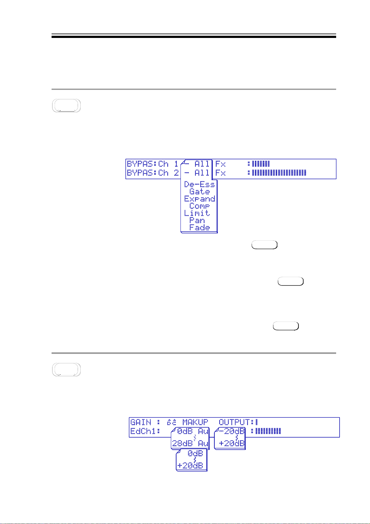
BYPASS
Primary function: Override all or one dynamics process(es). Because the M500 is really several
units in one, it would not be appropriate to have a single bypass switch which could only switch
all the Effects in or out of the signal path. For example, we may be using the two channels quite
independently in which case we need to be able to bypass them individually. Likewise, we may
wish to bypass individual Effects within a patch to aid setting up.
THE BYPASS DISPLAY
NORMAL MODE When the unit is configured for independent channel processing,
then only the channel selected with CHAN will be affected by
BYPASS.
STEREO BYPASS If the two channels are linked for stereo operation, then the
BYPASS key will automatically bypass both channels. For details
of the linking facilities, see the notes on the LINKS
SINGLE BYPASS To bypass a single Effect, hit the appropriate yellow Effect key
before BYPASS. The display will give a visual indication of the
bypass status.
CANCEL BYPASS To cancel BYPASS, hit any other key, except PATCH This special
condition of pressing PATCH retains the bypass mode to permit
the user to select another patch ready for loading.
OUTPUT
Primary function: Adjust and view output levels. Output functions as a master output level control
located at the end of the signal path. This functions independently for whichever channel is
selected unless the unit is configured for stereo operation in which case both channels will be
affected.
THE OUTPUT DISPLAY
Page 8
M500 OPERATORS MANUALCh 3 - 2
dc
MIDI VOLUME The output level may also be controlled via MIDI master volume controller
This is the facility to add make-up gain to the COMPRESSOR and
DE-ESSER to restore level lost during processing. This can be made
automatic by selecting AuAu or can be set manually to a specified amount.
If either the COMPRESSOR or DE-ESSER is set to its
will automatically be selected and the optimised gain setting will be
displayed.
information, if the MIDI option is set to
output gain display in dBs is only updated when the OUTPUT page is
constantly accessed, and any adjustment of the rotary controller will
revert the gain range between
volume" data value is scaled to operate between
formulae for setting output gain is:
OUTPUT GAIN (in dBs) = DATA VALUE - 90
MASTERVOL
-20db
-20db and
+20dB
+20dB. The MIDI "master
AUTO
AUTO mode, then AAuu
YES
YES. The actual
-90dB
-90dB and
+20dB
+20dB. The
METERS
Primary function: Simultaneously view input and output levels. A dedicated METERS screen
shows a bargraph meter display for the input and output levels for both channels simultaneously.
The input reading is the true input level, unaffected by the filters if selected. The bargraph is
constructed to have averaging characteristics with the addition of peak hold bars. To assist
reading these display meters, graduations are printed above and below the display window.
THE METERS DISPLAY
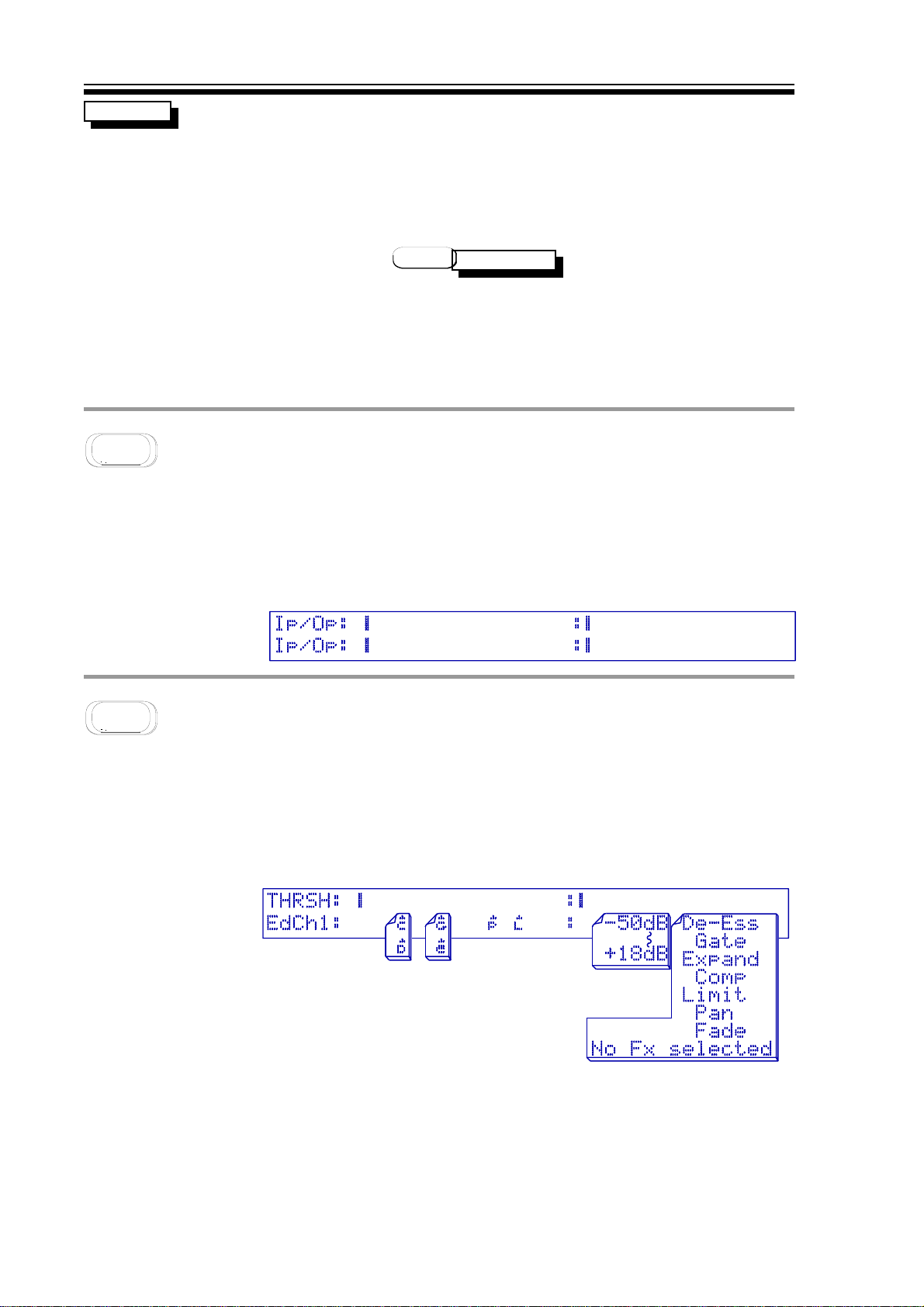
THRESH
Primary function: For visual adjustment of the threshold of dynamic processes. Though each
Effect's page display system gives access to that Effect's threshold setting, it is often useful to
be able to view and edit the threshold settings of all the assigned Effects from one page. On this
page, the top half of the display is dedicated to the input and output level meters while the
assigned thresholds are displayed on the line below.
THE THRESHold DISPLAY
Each Effect threshold is symbolised by its initial character with a small arrow head above it, listed
below. This character symbol moves along beneath the meter display as the value is changed to
give a visual representation of its setting. A more precise numeric value is also given in dBs. To
adjust a threshold value, it is necessary only to hit the appropriate Effect key and then use the
rotary controller.
Page 9
M500 OPERATORS MANUAL Ch 3 - 3
ˆˆC
C
ˆˆD
D
ˆˆE
E
ˆˆG
G
ˆˆL
L
ˆˆP
P
Character symbol representing the COMPRESSOR threshold.
Character symbol representing the DE-ESSER threshold.
Character symbol representing the EXPANDER threshold.
Character symbol representing the GATE threshold.
Character symbol representing the LIMIT threshold.
Character symbol representing the PAN audio trigger threshold.
The following points must be considered:
• Only Effects assigned to the current patch may be accessed.
• If two or more selected Effects have the same threshold setting, then the
one selected last will be visible with the other(s) hidden behind it.
• Hitting an Effects key twice in succession will exit from this page and
return to the Effects editing screen.
• If the M500 is in Stereo mode, then both channels will be adjusted
simultaneously; if the channels are independent, then CHAN can be
used to switch between them.
• Changing any threshold from
Auto
Auto to manual or vice versa is prohibited
when on this page.
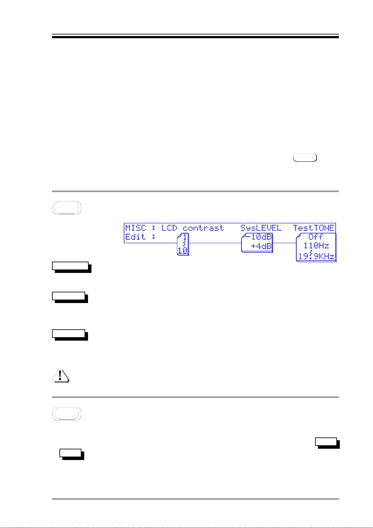
THE MISC DISPLAY
CONTRAST
SysLEVEL
Test TONE
MISC
Primary function: Setting the system operating level.
The LCD contrast can be set to suit the user viewing angle. Too pale a
display might result in the bargraph meters appearing sluggish. The range
is from 11 (pale) to 1010 (black).
System level must be set to match that of the connect equipment. An
incorrect setting will produce either a degraded signal to noise ratio, or,
overdriven / clipped audio. The two possible parameter settings are
+4dB
or
+4dB
The Test Tone oscillator can be set to generate a wide range of accurate
frequencies. Rotating the control knob gives a range of frequencies from
110
110HzHz to
19.9KHz
19.9KHz in third-octave steps. Though these are stable and
accurate in frequency, their amplitude and distortion specifications make
them unsuitable for tape machine calibration.
The EXPAND Effect LED should be off, (ie. EXPAND unassigned) for the
Test Tone oscillator to function correctly.
-10d
-10dBB
.
EDIT RECALL
Primary function: Comparison pre- and post-parameter adjustment. Whenever a patch is called
up for use, a copy of the original patch is held in memory allowing comparisons to be made using
the EDIT/RECALL key to toggle between the original and edited versions. The symbols
or are displayed in the lower left hand corner of the LCD window to identify whether Edit
Re..
or Recall is being auditioned. Obviously, some display windows such as METERS, MIDI and so
on have no usable Recall operation.
Ed..
Page 10
M500 OPERATORS MANUALCh 3 - 4
YES ACCEPT
The only function of this key is in response to screen prompts to confirm or store
changes.
ASSIGN
Primary function: Confirm and alter the order of dynamic processes. To set up a patch of one or
more Effects, the desired Effects have to be 'assigned' before they can be used. An assignment
is simply a selection of Effects that may be used together and also, if required, may be stored as
a user patch for later use.
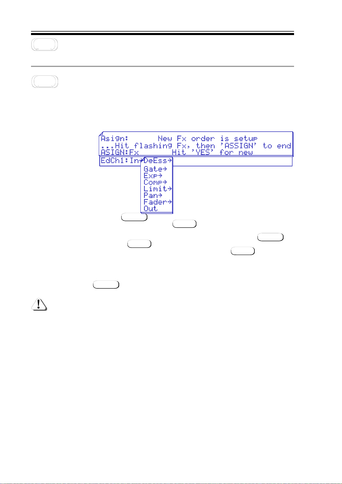
THE ASSIGN DISPLAYS
VIEW ORDER Pressing ASSIGN will display the current assigned order of Effects.
Pressing any key other than YES will not alter this order.
CHANGE ORDER A new combination of Effects can be assembled by pressing ASSIGN and
then hitting YES to confirm over-write of the current assigned order.
Any other key will be taken as a NO. After hitting YES all the yellow
LEDs above the Effects buttons will flash indicating that they are available
for use. The Effects buttons are then hit in the order in which you want to
patch the Effects, the first selected being the first Effect in the chain.
Once selected, the Effect's LED will remain lit rather than flashing. Press
ASSIGN to confirm your selection.
Selecting certain Effects will cause other LEDs to stop blinking indicating
that their inclusion further down the assignment chain is illogical. e.g. It
is illogical to follow a PANNER with anything other than a FADER, so if
PAN is selected first, then all the other LEDs apart from the FADER will go
out.
There are some other important points about the way that Effects can be assigned.
• Certain of the more complex Effects are only available in mono, but still
require that both channels of the unit are assigned (eg. see DE-ESS). This
is because the complex Effects require the circuitry of both audio
channels in order to function.
• Neither the COMPRESSOR and DE-ESSER, nor the EXPANDER and GATE
can be assigned simultaneously.
• If the GATE and COMPRESSOR are to be assigned together, the GATE has
to follow the COMPRESSOR, but to optimise the performance, the GATE
side-chain is fed from the input signal and not from the COMPRESSOR
output. This gives a better defined threshold and makes the unit easier to
set up.
Page 11
M500 OPERATORS MANUAL Ch 3 - 5
• When an incorrect selection is made, it is possible to re-start by hitting
ASSIGN followed by YES Once a satisfactory order has been
constructed, a prompt to hit ASSIGN again completes the procedure.
• If the M500 is not set in Stereo mode, then this procedure must be
repeated for the other channel where a different Effect assignment may
be set up if so desired. See also LINKS
MIDI
Primary function: Controls MIDI operation and functions. In these pages, the user can set up the
way in which the M500 responds to incoming MIDI data and also the way in which the M500
transmits MIDI information to either another M500 or a MIDI sequencer. MIDI can be used for
remote patch selection and may also be used to control the PAN Effect if MIDI control is
selected. Additionally, the very sophisticated GATE incorporated in the M500 can both generate
and respond to MIDI information. Other MIDI functions include the ability to dump memory
information via MIDI.
Because the MIDI side of the M500 is so flexible, this section contains several pages of
parameters, though for most applications, many of the settings can be left as they are.
Parameters that you may wish to change include the MIDI notes used to trigger the PAN and
GATE and the MIDI channels to which you wish the two audio channels of the unit to respond.
You may also wish to set the parameters for the FADE switch if you intend to use this facility
under MIDI control.
The top MIDI page functions as a basic MIDI input analyser. The main purpose of this page is to
verify that the correct MIDI information is being received while setting the unit up.
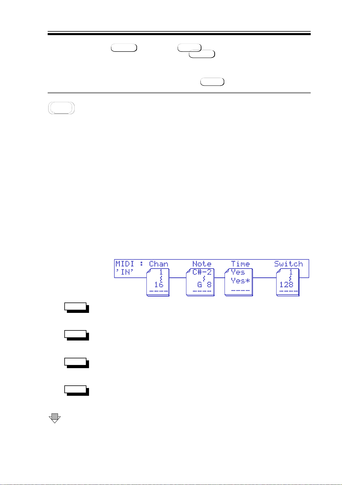
THE MIDI VIEW DISPLAY
VIEW Displays the incoming data MIDI channel(s). Information coming
Chan
from a sequencer will probably cause a blur as opposed to a static
number.
VIEW Displays incoming MIDI note on events. If a note is being played
Note
on and off very quickly it is possible for the note number display to
be invisible to the eye.
VIEW Displays the presence of MIDI clock events. Useful for setting the
Time
GATE or PAN timer trigger. An asterisk ** denotes time frames and
Yes
Yes indicates a MIDI Clock Start has occurred.
VIEW Incoming MIDI switch numbers are displayed. Its purpose is to
Switch
assist with FADE switching and REMOTE CONTROL VIA MIDI, see
3
DOWN The first parameter page has four parameters which are adjustable
separately for each audio channel. These four parameters are
stored when a User PATCH is saved.
Page 12
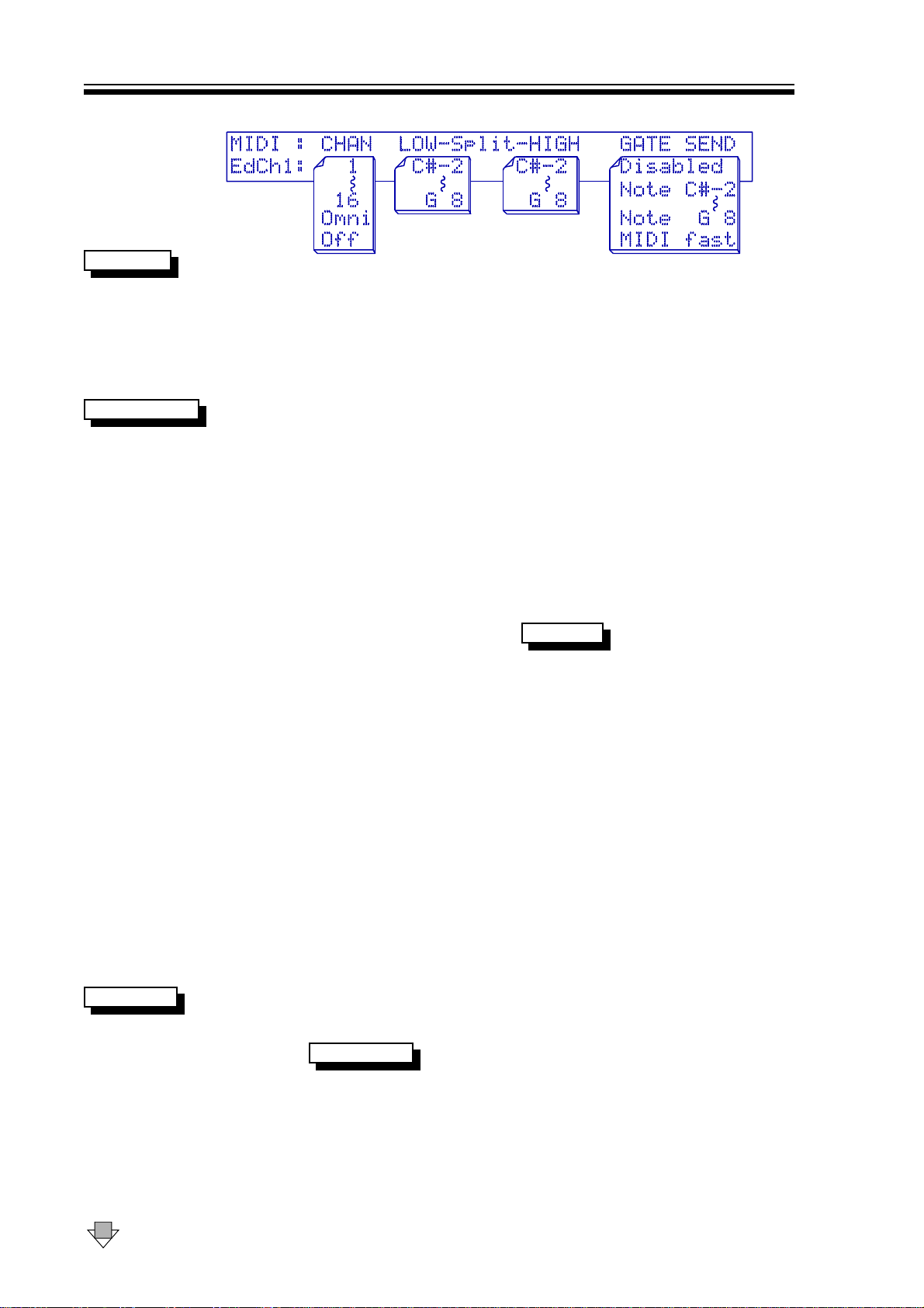
FIRST MIDI PARAMETER DISPLAY
M500 OPERATORS MANUALCh 3 - 6
MIDI CHAN
A receive and transmit MIDI channel can be set differently for both
audio channels, ranging from 11 to 1616. Other options can be
OFF
or
OFF. In
OMNI
OMNI mode, the M500 will respond to data received on
OMN
OMNII
any MIDI channel but will always transmit MIDI data on channel 1.
The OOFFFF option is offered more for security, as it prevents any
response to incoming MIDI and nothing will be output from events
occurring on the corresponding audio channel.
Low-SPLIT-Hig
These two note values are applicable to the PAN and GATE
functions of the M500. The parameter sets the lowest and highest
MIDI note which will be accepted by the M500.
MIDI PAN When used with PAN set to trigger from
MIDI
MIDI, the low note and
high note correspond to the extreme left and right stereo image
PAN positions. MIDI notes between these two extremes will then
control the PAN position proportionally. An example is given by
loading PRESET FACTORY PATCH number 124. See PATCH 13 and
3.
MIDI GATE When used with the GATE, the note range selected will fire the
GATE envelope when GATE is set to
TRIGGER
MIDI note
MIDI note. Any
notes outside the split range are ignored.
ONE NOTE ONLY If the GATE needs to be set so as only to respond to a single MIDI
note, then the low and high split points should be set to the same
note value. See PATCH 13 and 3.
DEAD ZONE SPLIT One interesting feature is that if the high note split point is set to
a lower note value than the low split point, a new situation is
created in which the notes bounded by the split values are inactive
while notes outside this zone are still active. This 'dead-zone' is not
applied to the PAN as it would be impractical.
ALL NOTES TRIG There are two ways to make the M500 respond to all MIDI note
values; one is the obvious solution of setting the split points to
-2
cover the whole MIDI note range CC
<
<
-2 to G8G8, but the same result
may be achieved by setting the high split point just one semitone
below the low split point which is often quicker.
GATE SEND
GATE SEND allows a MIDI note value to be selected which will be
transmitted whenever the GATE is triggered. The velocity
associated with the MIDI note is related to the GATE
PEAK LEVEL
parameter. The note on time will correspond to the
opening time of the GATE envelope. This may be set to any MIDI
note or
through, another possible setting called
Disabled
Disabled. If the MIDI notes are scrolled all the way
MIDI FAST
MIDI FAST appears. This
should only be used when two or more M500s are linked and
allows GATE trigger information to be transmitted from one unit to
the other approximately three times faster than is normally
possible over MIDI.
DOWN The second display page contains the MIDI triggering parameters.
Page 13
M500 OPERATORS MANUAL Ch 3 - 7
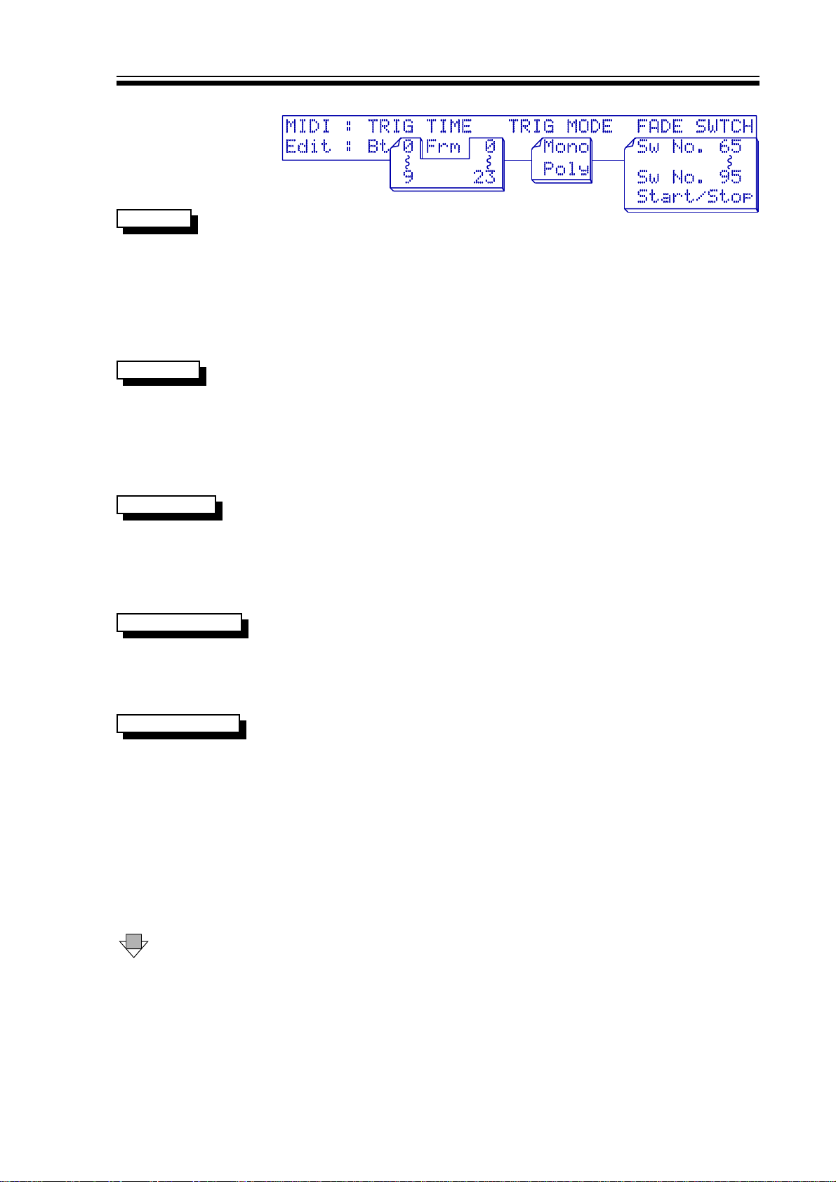
SECOND MIDI PARAMETER DISPLAY
TRIG TIME
TRIG MODE
FADE SWITCH
MIDI START/STOP
The TRIGger TIME relates to the way in which the unit responds to
incoming MIDI clock in either the triggered GATE or PAN modes.
The adjustment range goes up to a maximum of 99 beats and 2233
frames where frames represent individual MIDI Clock pulses. In a
song running 4/4 time, this is one frame less than 2 whole bars and
2 beats. For details on how this feature is used, see the sections
on the GATE and PAN Effects. A MIDI Start instruction restarts the
counter to zero.
TRIGger MODE has only two options which may be set to either
MONO
MONO or
when triggered from MIDI notes. In
will retrigger the Effect while in
POLY
POLY and again relates to the GATE and PAN affects
POLY
POLY mode, each new note-on
MONO
MONO mode, no new trigger will
be accepted until all previously received MIDI notes have been
turned off. Remember that only notes within the current high and
low split range will be recognised.
The FADE SWITCH parameter relates to the way in which the
autofade function responds to incoming MIDI information. The
M500 is capable of both fade-ins and fade-outs and these may be
triggered manually from the keypad, or from either a MIDI
Start/Stop command, or from MIDI switches, often called
controllers.
Providing that FADE SWITCH is set to
Stop/Start
Stop/Start and the FADER is
assigned and set to trigger from MIDI, then a MIDI Start
instruction will cause a fade-in at the selected fade-up speed and
a MIDI Stop instruction will trigger a fade-out at the selected fade
down speed.
SWITCH NUMBER
DOWN The third page covers MIDI PATCH CHANGES and MASTER
A valid FADE SWITCH (or controller number) will be within the
range 65 to 95 inclusive (decimal). Controller data will need to be
in the range 64 to 127 to be accepted, values below this being
ignored. If MIDI switches are used, these cause the FADER to
change states, in other words, if the FADER is open, the signal will
be faded out, but if the FADER is closed, a valid switch will cause
the signal will be faded in. An example of a legitimate MIDI
instruction to operate a FADE event would be:
Controller Status + Channel Number B0 hex
Switch (Controller) Number 50 hex 80 dec
Switch (Controller) Data 7F hex 127 dec
VOLUME.
Page 14
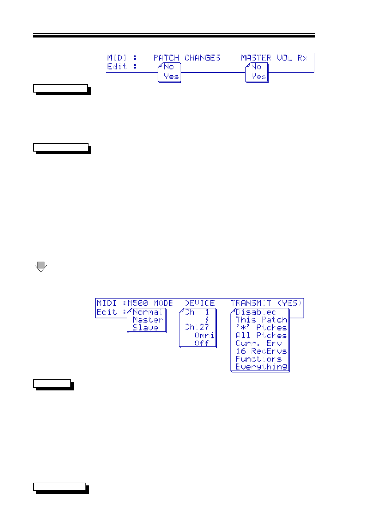
THIRD MIDI PARAMETER DISPLAY
M500 OPERATORS MANUALCh 3 - 8
PATCH CHANGES
MASTER VOLUME
DOWN The fourth (bottom) page covers M500 MODE, DEVICE and
When set to
YES
YES, allows the M500's 128 patches to be remotely
selected and loaded ready for use over MIDI using standard MIDI
program change messages. When the NONO option is selected, the
M500 will not respond to incoming program changes, but all other
relevant MIDI information will still be accepted. This parameter
setting is also repeated within the PATCH screens, which is
another obvious location to need to adjust this parameter.
MASTER VOLUME set to
YES
YES enables the output gain of the M500
to be controlled by MIDI controller 7, "master volume". The actual
output gain display in dBs is only updated when the OUTPUT page
is constantly accessed, and any adjustment of the rotary controller
will revert the gain between
-20db
-20db and
volume" data value is scaled to operate between
+20dB
+20dB. A data value of 110 (06E hex) or above, will set the output
+20dB
+20dB. The MIDI "master
-90dB
-90dB and
gain to +20dB and a value of 0 will set the gain to -90dB. The
formulae for setting output gain is:
OUTPUT GAIN (in dBs) = DATA VALUE - 90
An example of a valid MIDI instruction to alter the output gain
would be:
Controller Status + Channel Number B0 hex
Master volume (Controller) Number 07
Controller Data (eg set 0dB) 5A hex 90 dec
TRANSMIT.
THE FOURTH MIDI PARAMETER DISPLAY
M500 MODE
M500 MODE section enables more than one M500 to be used in
the same MIDI system; if only a single M500 is in use, this should
be left set to
In a multiple M500 setup keypad and rotary control on a master
unit can be echoed on other slave units. Within one MIDI
connection circuit, only one unit should be configured as
with all other units wishing to be communicated with being set to
SLA
SLAVEVE. It is important that all communicating M500's be set so
that matching audio channels have to identical MIDI channels for
both audio channels. For example, if the
audio channel set to MIDI channel 4, then so should all the
units. The right audio channels should be set to a different MIDI
channel.
NORMAL
NORMAL. The other options are
MASTER
MASTER unit has the left
MASTER
MASTER and
SLAVE
SLAVE.
MASTE
MASTERR
SLAV
SLAVEE
DEVICE NUMBER
DEVICE parameter selects the 'Exclusive data' channel number
Page 15

M500 OPERATORS MANUAL Ch 3 - 9
127
which may be in the range 11 to
127,
OMNI
OMNI or
OFF
OFF. Selecting
OFF
OFF
makes the unit ignore any Sysex data received and disables the
Transmit function though other MIDI data is handled as usual. In
order to dump data to either another M500 or to a MIDI sequencer,
the send and receive device numbers must be set the same, or the
receive device set to
ChOmni
ChOmni in which case the send channel is
irrelevant.
TRANSMIT
The TRANSMIT option is used to select exactly what data will be
transferred during a dump. When not in use, the parameter should
be set to
DISABLED
DISABLED to avoid unintentional operation. To initiate a
data dump, the desired data type should be selected and then
YES will start the data dump. The data to be transmitted may be:
1: The current Patch,
2: * Patches (41-50),
3: All 50 User Patches,
4: The current recorded Envelope ( selected on the
RECORDed envelope page, or the GATE user envelope
parameter)
5: All 16 recorded Envelope memories,
6: The M500 Panel Functions (eg MIDI parameters. etc)
7: or Everything.
In the latter mode, the entire memory of the M500 is transmitted.
This setting is useful for configuring a new M500 from scratch
making it a clone of the master unit. Additional information on 2 ,
2, 3
TRANSMIT PROBLEMS When large amounts of data are being sent or received a short
time delay is required between every second data block. The
ERROR
ERROR message will be displayed if this time delay is not
DAT
DATAA
included.
LINKS
Primary function: Joins both channels or Effect modules for stereo operation. This is an extremely
important area of the M500 and determines which Effects are to be linked between the two
channels.
There are three important and distinct areas covered by Linking listed on the following pages:
The four discrete Effects links.
The Stereo link.
The setup of the Inputs and Outputs of the M500.
The individual Effects Links should not be confused with stereo operation. Linked Effects will
always have the same parameters on both channels and any adjustments to the selected channel
will be emulated on the other channel - but the two channels' side-chains still operate
independently unless the master Stereo link is turned on.
This is a convenient method of setting up two channels, as it is only necessary to edit one
channel and all changes will be duplicated in the other. Links may then be turned off again if
further editing to one channel or the other is required.
Page 16
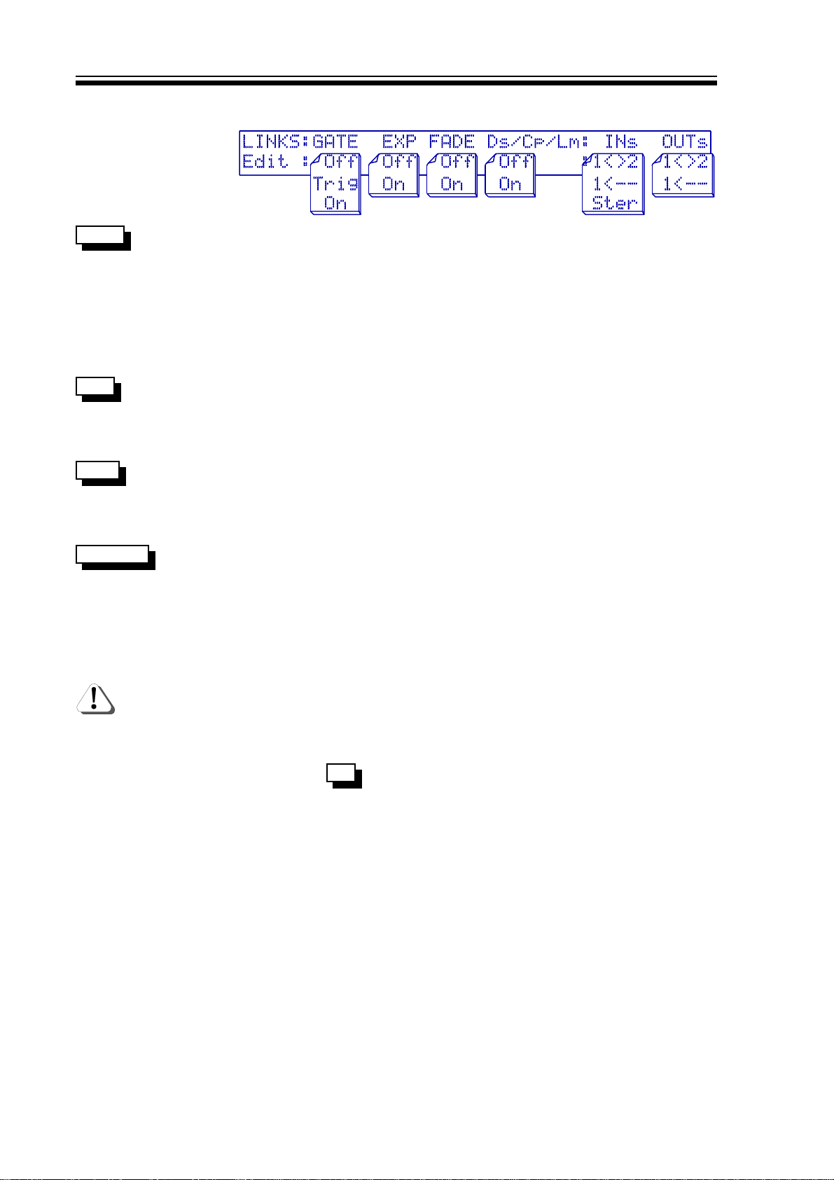
THE LINKS DISPLAY
M500 OPERATORS MANUALCh 3 - 10
GATE
EXP
FADE
Ds/Cp/Lm
GATE link has three possible options. OnOn will copy the current
channel's parameters to the other channel. Any further GATE
parameter adjustments will be duplicated on the other channel.
Off
Off reverts to normal single channel operation. GATE link also has
TRI
a
TRIGG option. This forces channel 2 to follow the triggering of
channel 1 and it should be noted that though the GATE gain
reduction metering on channel 2 is still valid, the GATE signal
meters are irrelevant.
EXPand link has only two options, OnOn or
Off
Off. OnOn will copy the
current channel's parameters to the other channel. Any further
EXPANDER parameter adjustments will be duplicated on the other
channel.
FADE link has only two options, OnOn or
Off
Off reverts to normal single channel operation.
Off
Off. OnOn will copy the current
channel's parameters to the other channel. Any further FADER
parameter adjustments will be duplicated on the other channel.
Off
Off reverts to normal single channel operation.
DE-ESS / COMPRESS / LIMIT link has only two options, OnOn or
On
On will copy the current channel's parameters to the other
Off
Off.
channel. Any further COMPRESSOR or LIMITER or DE-ESSER
parameter adjustments will be duplicated on the other channel.
Off
Off reverts to normal single channel operation.
NO PAN LINK PAN is a two-channel Effect, so no linking option is offered.
Although the DE-ESSER and LIMITER may be Linked, in most
cases, it is desirable to turn Links
Off
Off as these two processes
produce better results if the two channels are processed
independently.
M500 IN STEREO Select
Ster
Ster when the M500 is to be used for processing a
INs
stereo signal and it influences several important operational areas.
Because switching to stereo has several implications, it is worth
reading this section thoroughly.
STEREO LINKS Stereo is a master setting for the current patch assignment and
will automatically switch OnOn all of the Links for the individual
Effects assigned, and set both channels' parameters the same. If
it is required to set up a stereo Effect where both channels are not
the same, or where one or more Effects need to be used
independently rather than as a stereo pair, then the appropriate
Stereo Link or Links should be disabled after selecting
Ster
Stereo and
before further adjusting the parameters. There is no obligation to
leave the individual Effects linked after selecting
Ster
Stereo and any
Effects that are linked when Stereo is selected will function as true
stereo pairs.
Page 17

M500 OPERATORS MANUAL Ch 3 - 11
STEREO GLOBAL Other relevant parameters are also linked such as OUTPUT GAIN,
COMPRESSOR DC MAKEUP and the function of the BYPASS
button. This ensures that the user has not accidentally overlooked
any parameters that might otherwise cause the channels to
behave differently. However, the user must ensure that the
parameter is set to
1<>2
1<>2 to allow dual-channel output operation.
OUTs
STEREO SIDE-CHAIN When in stereo mode, the side-chain sensing of the different sections is
automatically switched to be appropriate for the treatment of a stereo
source. For example, the compression-based Effects use an average of
the left and right channel signals to prevent unwanted image shifts when
one channel has significantly different dynamics to the other.
Any non-symmetrical stereo patch is stored as a stereo patch pair
and occupies two patch memory locations. The M500
automatically registers any difference between the two channels'
parameters so no decision need be made on the part of the user.
If both channels are identical in all respects, then a stereo patch
will be saved in a single patch location (saving memory space).
Recalling one patch of a stereo pair will automatically load the
other.
It is also possible to set up the way in which the input and output connections are handled for a
particular sequence of Effects as explained below.
1<>2
INs
1<>2 Located in the LINK menu, INs is used to set up the input mode of
the M500. The setting of
1<>2
1<>2 configures two inputs for channels
that are to have independent Effect assignments. This can be
thought of as dual-mono operation.
1<--
INs
1<-- Selects channel one as the mono input for Effects requiring only
a mono input such as the DE-ESSER or the PANNER if a mono
source is to be PANned between the two outputs. It may also be
used when two chains of Effects are needed but where the side
chain signals derived in channel 1 are required to control channel
2 also.
INs
Ster
Ster
Ster
Stereo switches the M500 to a stereo input, stereo output unit
with all the implications discussed in the STEREO section.
OUTs
As with the inputs, the outputs may be set in different modes for
different applications. The M500 has two possible modes allowing
for dual channel operation or summed into mono where both
channels are summed at the output and routed to output 1.
OUTs
1<>2
1<>2 Setting OUTs to
1<>2
1<>2 is the normal setting and must be selected
either for dual-mono or conventional two channel operation.
OUTs
1<--
1<-- By selecting OUTs to
the output to form a mono signal available at the output of channel
1. This facility is necessary for some of the more advanced Effects
such as split-band compression and complex DE-ESSing.
1<--
1<--, the two channel signals are mixed at
Page 18

M500 OPERATORS MANUALCh 3 - 12
To avoid possible confusion as regards the LINK settings,
especially in the cases of the more advanced Effects, it is
recommended that the user experiment with a preset patch which
includes the desired linked Effect and make tiny adjustments,
rather than attempting 'Linked Effects' from scratch.
FILTER
Primary function: Side chain filter for GATE and DE-ESSER. If the FILTER is assigned to either the
DE-ESSER or the GATE, the top display page will show where the filter is 'patched' (ie. where it
is placed in the chain) and how it its functioning, otherwise the display will read:
more complex DE-ESSING functions, the display alters for each channel depending on whether
the pass-band or stop-band is being veiled/edited.
THE MANY POSSIBLE FILTER VIEW
DISPLAYS EXPLAINING FILTER
USAGE AND FUNCTION
Unused
Unused. For the
The method of display of filter pass band is a bargraph beneath a frequency scale showing the
upper and lower cutoff limits of the filter. More filter cut-off frequencies are present than are
shown on the upper scale due to the limitations of the LCD.
DOWN
THE FILTER DISPLAY
FILTER Low Frequency To adjust pass-band frequency, it is necessary only to hit LEFT
and then use the rotary controller.
FILTER High Frequency Hit RIGHT arrow and use the controller to adjust the upper
frequency setting.
FILTR
Notice the lefthand word
FILTR
FILTR in UPPER case. This page and the
page below are identical except that the signal monitored at the
output of the M500 is different. On this page, the monitor signal
is the filter output which functions in much the same way as the
'side-chain listen' facility used on traditional frequency-conscious
gates. eg DRAWMER DS201.
Page 19

M500 OPERATORS MANUAL Ch 3 - 13
DOWN Makes a change only in signal monitoring
Filtr
The lefthand word
Filtr
Filtr in lower case. Functions in exactly the same way
as above but the monitor signal is now the output of the GATE or
DE-ESSER to which the filter has been assigned, and not the actual signal
passing through the filter.
Assigning the filter to the DE-ESSER takes priority over the GATE as the
DE-ESSER is not able to function in any mode without use of the filter,
where as the GATE can.
PATCH
Primary function: Store and retrieve, preset and user patches. This function button accesses
three screens, the top of which is used to select the patch number you wish to load a program
from, or the patch number in which you want to save the program on which you have been
working. Keep in mind that unless stereo linked Effects are in use, loading and saving applies only
to the audio channel currently selected. Remember that patches 51 to 128 are presets and cannot
be changed, erased or overwritten. Patch titles are also shown on this screen.
THE PATCH DISPLAY FOR LOAD
LOAD PATCH Patches can be loaded by rotating the encoder knob until the desired
patch number is reached and then hit YES . The patch will be loaded
into the current channel.
USER PATCH A
User
User patch is in the number range 11 to 5050. This type of patch can
be modified, overwritten and erased.
USER * PATCH A
User *
User * patch is in the number range 4141 to 5050. This type of patch
can be modified, overwritten and erased. The ** asterisk denotes
that they can be dumped as a 'short' block of data via MIDI. It is
recommended that the most popular patches be stored in this 41
to 50 band.
PRESET PATCH A
Preset
Preset patch is in the number range 5151 to
128
128. These types of
patch can be modified, but never overwritten or erased.
DOWN To the Save patch screen where it is possible to name and save
patches being stored in User locations 1 to 50. This page will not
be shown if presets are in use.
The LEFT and RIGHT buttons are used to move through the ten possible
characters of the title and the rotary controller used to scroll through the alphabet. Upper and
lower case letters, numbers and some symbols may also be used. The user is not prevented from
giving two different patches the same name but this may give rise to confusion!
Page 20

M500 OPERATORS MANUALCh 3 - 14
THE PATCH DISPLAY FOR SAVE
SAVE PATCH(es) YES will save the current patch from the current channel. The
SAVE Patch option will automatically detect which LINK mode (eg.
Stereo) is in operation and will offer various suitable save
methods. If dissimilar stereo patches are being saved, the
following display will be seen.
SECONDARY PATCH
DISPLAY FOR A
STEREO SAVE
DOWN The last (bottom) screen encompasses MIDI CHANGES and
MEMORY PROTECTION.
MIDI CHANGES
When set to
YES
YES, enables the M500 to utilise MIDI patch changes
and also to transmit them. These MIDI commands will be on the
corresponding MIDI channel set on the MIDI screen). This
parameter adjustment is replicated on the MIDI pages.
LAST PATCH DISPLAY
MEMORY PROTECTION
This will prevent the user patches from being overwritten and
should be disabled if you wish to store a patch you have edited.
Attempting to store a patch with the protection turned on will
cause an immediate jump to this parameter to warn you that the
protection mode is set.
If PATCH CHANGES is set to
YES
YES on this screen or the MIDI page,
then a MIDI patch change command will be output whenever a
patch is down-loaded from the front panel.
RECORD
Primary function: Generate User Envelopes for the GATE Effect. This page is used exclusively with
the GATE Effect when it is required to make use of the GATE's ability to super-impose recorded
sound envelopes. This offers far more complexity than the standard 'Peak-Attack-Hold-Release'
envelope characteristics.
For trouble free use, the following points must be considered:
• GATE will need to be set to
TYPE
RECORDED
RECORDED.
• Only audio envelopes present on channel one will be accepted.
Page 21

M500 OPERATORS MANUAL Ch 3 - 15
• The white graduation above the display window can be used to
maximise the input envelope amplitude.
• When the envelope is later used with the GATE Effect, for it to
respond as a true noise gate envelope the following should apply:
The input level during record should reach 0dB at least once.
Any input level above 0dB will react similar to GATE PEAK.
The final input level of the envelope must be as close to -90dB as
possible for the GATE to fully close.
FIRST RECORD DISPLAY
RECORD To maximise the storage rate and resolution of a recorded
RATE
envelope it is necessary to approximate the duration of the sound
about to be recorded. This rate can be re-adjusted later at replay
time, but should be set to just longer than the sound envelope
being recorded. This time ranges from
RECORD The THRSH (threshold) is only applicable if the recording process
THRS
0.5
0.5 second to 2020 seconds.
is going to be triggered from an Audio source on channel 1. The
parameter ranges from
-40dB
-40dB to
+15dB
+15dB. For easy operation, this
level can be considered as a noise-gate threshold.
TRIGGER The envelope recording process can be set to start from one of
SOURC
three events. If Audio is selected then the audio threshold level
must be adjusted and recording will commence automatically
when channel one's input signal exceeds the set threshold. YES
can be used to start the process. Alternatively, any valid MIDI note
on the correct MIDI channel and within the Hi-Low split range of
audio channel one will start the record process.
READY TO RECORD The screen prompts with
YES to prime
YES to prime, and on hitting YES a
new screen is displayed which shows the input signal relative to
the threshold and also the memory available for envelope storage
as a dotted line which 'fills' in the form of a bargraph once
recording starts.
SECOND RECORD DISPLAY
Page 22

M500 OPERATORS MANUALCh 3 - 16
FINISHED RECORD DISPLAY
ENVELOPE NUMBER Once recording is complete, the envelope number is displayed and
may be changed, ranging from 11 to 1616. If a previously recorded
number is selected, this will be overwritten.
RECORD NAME The envelope may be given a title of up to ten characters. If a
previously recorded envelope is selected, this will be overwritten.
RE-START RECORD If the recording is unsuccessful or not the required envelope
shape, it is necessary to press RECORD again to return to the
initial page.
CANCEL RECORD Envelope recording can be aborted at any time by pressing any
key.
CHAN 1 / 2
This key selects the left or right audio channel to be edited or viewed. The left channel is denoted
by a red status LED and the right by a green LED. If a stereo linked patch is accessed, the
selected channel LED will remain lit and the other will flash.
Page 23

M500 OPERATORS MANUAL Ch 4 - 1
CHAPTER 4
BASIC EFFECT OPERATION
The Effects are accessed via the seven yellow keys on the bottom row of the keypad, and an
Effect may be selected for experiment by hitting ASSIGN then YES and then your choice
of Effect. Confirm your selection. Then hit the Effect key again to access the parameters on the
appropriate screen display. If you are new to the M500, it is certainly worthwhile setting some
time aside to explore the Effects in isolation before attempting to combine them.
Most of the Effects behave in a similar manner to their discrete, all-analogue counterparts, the
main difference being the additional parameters and features available plus the ability to store
Effects settings as patches for recall at some future time. In order to present the Effects in a
more understandable order, they will be introduced in a different order to that in which their
buttons appear on the front panel.
As stated earlier, the top page of each Effect is given over to metering while the next page gives
access to the most often used parameters. More advanced features are located on lower display
pages and these may be conveniently ignored if they are not required.
This section is intended as an introduction to the Effects and covers only their basic operation.
For details of the advanced parameters and facilities, refer to the advanced section. Having said
that, many of the advanced functions are self explanatory, so feel free to experiment without
further in depth reading. Very often, just knowing that a feature exists provides enough clues to
get it to work.
BASIC GATE
The GATE can perform all the functions of a stand-alone GATE such as the DRAWMER DS201.
However, the most common application of a GATE is to turn off the signal path when the input
signal falls below a threshold set by the user in order to remove noise during pauses. Full
envelope control is provided to enable gating to be performed with the minimum side-effects to
the wanted signal.
For basic operation, the GATE TYPE should be set to
is to be found on the last (bottom) GATE display page. If this parameter is set to
RECORDED
RECORDED, then different GATE parameter pages will be displayed.
DOWN one screen from the meter page gives direct access to all the parameters necessary
for conventional gating purposes. The Threshold level may be set by the user and this is normally
set as low as is possible without allowing noise and crosstalk to cause false triggering.
The Attack should initially be set to the shortest time possible, though if a click is audible when
the GATE opens, the attack time should be lengthened until the click no longer occurs. In
practice, the fastest attack times are only necessary for drums and percussive sounds.
The Hold time is designed to prevent the GATE from opening and closing rapidly if the decay
characteristic of the signal being processed is erratic and for most applications, a value of 50mS
or so will prevent chattering, even on low bass notes.
NORMAL
NORMAL and this parameter
The Release time determines how quickly the GATE closes once the input has fallen below the
threshold and should be set long enough so as not to truncate sounds having a naturally slow
decay.
Range sets the amount of attenuation which occurs when the GATE is closed. This control is
necessary because it is not always desirable to have the signal fully turned off; sometimes a
sufficient degree of noise reduction can be achieved by setting a Range of only 10dB or so and
in difficult circumstances, this might reduce any audible side-effects. Additionally, in situations
where fast GATE opening is required, the GATE will open more rapidly, the smaller the range
Page 24

M500 OPERATORS MANUALCh 4 - 2
setting in dBs.
In other applications such as separating dialogue from background noise, it is often more natural
to merely attenuate the background noise rather than attempt to remove it completely.
Side-chain filtering is available though the access to this is via a page further down the menu. The
filter is set up using the FILTER key on the front panel and it is used exactly like the filter on a
DS201 GATE. The Key Listen facility is also accessed by means of the FILTER key.
Features on later pages give access to the 'Peak' facility unique to the M500. This allows the GATE
to actually add a degree of level boost to the front of a transient sound giving it more impact and
one of the main applications is in processing drum and percussion sounds. The available
parameters are very simple and mainly self-explanatory:
The more advanced features include: Selection of Audio or MIDI GATE triggering, Predelay, SideChain filtering, use of Recorded Envelopes and GATE/DUCK selection.
The GATE cannot be selected for use at the same time as the EXPANDER, and if
a DE-ESSER is assigned, then the filters will have been commandeered by the
DE-ESSER and will not be available for use in the GATE's side-chain.
BASIC EXPAND
The EXPANDER may be set up in a similar way to a GATE in order to remove or attenuate low level
noise, but by selecting a mild expansion ratio, it can also be used to increase the dynamic range
of programme material. For noise removal work, the threshold should be set as low as possible
with a ratio of 1:2 or greater while for dynamic range expansion, the threshold may be set at or
close to 0dB with a suggested ratio of 1:1.5 or less.
There is only one display page relating to the EXPANDER all of which comes under the brief of
Basic Operation.
The parameters are exactly the same as for the basic GATE (Threshold, Attack, Hold, Release and
Range) with the addition of Ratio. This sets the relationship between the input signal and the
output signal for levels falling below the threshold. A 1:2 ratio, for example, means that for
signals falling below the threshold, a 1dB reduction in input level will result in a 2dB reduction in
output level.
The EXPANDER cannot be assigned at the same time as the GATE.
BASIC COMP
The COMPRESSOR may be set to NORMAL, in which case it functions as a conventional ratiotype COMPRESSOR, or it may be set to SOFT whereupon it functions as a soft-knee device. The
available parameters are the same as for the EXPANDER and there is the option of selecting
AUTO attack and release times as well as setting these manually. It must be understood, though,
that while an EXPANDER attenuates signals that fall below the threshold, a COMPRESSOR
attenuates only those signals exceeding the threshold.
COMPRESSORs are generally used to reduce the dynamic range of a signal in order to minimise
level fluctuations and it is invariably necessary to compress pop vocals to some degree. For
signals with varying characteristics such as vocals or complex mixes, the Auto settings often
produce the best result.
Creative Effects can be achieved by setting a deliberately long attack time when working with
percussive or plucked sounds as this allows more of the attack portion of the sound to pass
through un-attenuated giving a degree of punch.
Page 25

M500 OPERATORS MANUAL Ch 4 - 3
BASIC LIMIT
LIMITERs are used to impose more firm control over signal dynamics than a COMPRESSOR and
are often used to set an absolute maximum level that the signal being processed must not
exceed. Technically, the function of a LIMITER is identical to that of a COMPRESSOR but the ratio
is higher. This Effect has the same user-adjustable parameters as the COMPRESSOR. There is
a choice of manual or auto (programme dependent) release time.
The lowest ratio that can be selected is 2:1 whereas the maximum is 90:1 which, for all practical
purposes, sets an absolute preventing the input from exceeding the threshold by more than a
fraction of a dB. It is commonplace to assign a LIMITER following a COMPRESSOR, especially
where the COMPRESSOR is set to a low ratio or has a long attack time. In these circumstances,
the COMPRESSOR can still pass very high peak levels and it is useful to employ a LIMITER as a
second line of defence.
The LIMITER attack time is variable up to a maximum of 5mS allowing the user to decide what
duration of clipping or overload is tolerable. For most material, badly clipped signal peaks of less
than 2mS in duration are imperceptible. However, for applications where instant control is vital,
the LIMITER attack time may be set as low as 20µS.
BASIC PAN
The M500 can be used to PAN a mono signal between the two channels with a choice of eight
modulation waveshapes. For conventional PANning, either the Sine wave or Triangle wave will
give the most natural result, but other waveforms are included for special Effects.
Because of the sophistication and diversity of the PANNER, only its more basic options will be
described in any detail, though a full description of the features is available in the main manual.
The first page gives access to the most important parameters, these being RATE, RANGE, WAVE
and PHASE. RATE sets the speed of the PAN Effect while RANGE determines the stereo width
of the Effect. The maximum value of 60dB will give the widest possible PAN. Of course the M500
will need to feed a pair of mixer channels PANned hard left and right for this to be achieved.
WAVE gives a choice of eight control waveforms starting with Sine while Phase determines
whether the unit functions as a PANNER or a tremolo unit. If PHASE is set to in, then the level of
both channel changes together rather than alternating.
The advanced features of the PANNER give a choice of Audio, MIDI Note or MIDI Beat triggering
and it is possible to set the PAN start position to any point between the extreme left and right
PAN positions. There is also an envelope function which allows the PAN width to increase with
time after triggering. A similar facility is available to add 'decay' to the PAN width after triggering
if so desired.
Because the PANNER generates a stereo output, it requires both audio channels
of the M500 to be assigned to the PANNER. A single channel may be used to
create a tremolo effect.
Page 26

M500 OPERATORS MANUALCh 4 - 4
BASIC FADER
In the FADER mode, the M500 can be used to fade in or out either a stereo signal or two mono
signals. In the mono mode, the two channels can be given different fade in and out times though
the same trigger source is automatically selected for both channels.
There are three possible trigger modes which may be selected from the FADER menu: View, MIDI
and Timer. The fade up and down times may be set independently as may the attenuation range
which should be set to 90dB if a complete fade to silence is required. Remember that the times
are 'per 10dB' so, setting a 1 second fade time and a 90dB range will mean the fade takes 9
seconds to complete.
In View trigger mode, a fade is initiated by moving to the meter (top) screen of the FADE menu
and then hitting either the right or left arrow buttons. The left arrow initiates a fade down whereas
the right arrow initiates a fade up.
Though the FADER levels are shown on the gain meter, this has a range of only
40dB and so the fade may not immediately register on the meters until it comes
into range. This is especially true of long fade-ups from maximum attenuation.
If the fader is closed and it is required to open it, the FADE key should be hit twice in succession.
In MIDI trigger mode, the triggering event is as selected on the MIDI menu under the FADE
SWITCH option.
When TIMER is selected, the final screen is used to set the necessary parameters. In principle,
the FADER is programmed to start a set time after it is triggered by the arrival of an audio input
exceeding -10dB. This is useful when setting up a fadeout at the end of a song as the timer can
be triggered by the first beat of the song and the timer set so as to commence the fadeout at the
appropriate point towards the end of the song.
Once the song has ended and the audio input has fallen below -30dB for a period exceeding 5
seconds, the timer automatically resets.
The easiest way to set up the timer is to set the timer MINUTES parameter below 0 which arms
the system. Playing the desired program material will trigger the counter as soon as the level
exceeds -10dB and this will continue to count until the YES key is hit to signify that the FADE
should start. This allows the fade start point to be set during a dry run after which the mix can be
run as many times as is necessary and the fade will always start at the same point.
BASIC DE-ESS
Though the first Effect as regards front panel layout, the DE-ESSER has been left until last as it
helps to have un understanding of the other Effects before using it.
DE-ESSing is basically frequency conscious compression used to 'pull down' the gain of a vocal
track when loud, sibilant "S" sounds occur. This is done by placing a filter or equaliser in the
detector side-chain making the COMPRESSOR more sensitive to sounds in the area of the audio
spectrum where sibilance occurs which is normally between 3KHz and 8KHz depending on the
characteristics of the vocalist.
The DE-ESSER uses both the COMPRESSOR section and the FILTER which means
that the COMPRESSOR cannot be assigned to the same patch as the DE-ESSER
and also, the GATE is unable to use the filter.
Page 27

M500 OPERATORS MANUAL Ch 4 - 5
It is necessary to set up the filter via the FILTER key and menu so that only the most sibilant
sounds are passed. This is best done by monitoring the filter output while the offending signal
is present and then tuning the filter so that it captures as much as possible of the sibilant sound
and as little as possible of the rest of the material.
Back on the DE-ESS page, the parameters can be set up in a similar way to setting up the
COMPRESSOR. It is important to set the threshold value carefully while monitoring the processed
signal as over-processing can cause noticeable dips or dulling in the sound. As with the
COMPRESSOR, both NORMAL (ratio) and SOFT (soft-knee) modes are available, SOFT generally
being least obtrusive but NORMAL being more positive in difficult situations.
Most regular jobs can be tackled with the basic DE-ESSER but more complex DE-ESSing systems
are available amongst the advanced features in later menu pages. The other options are: Singleband De-ess, Two-band Compression and Two-band Complex Compression. These more complex
systems require both audio channels in order to function, though the basic Full-band de-esser
may be assigned as a dual-channel Effect.
For a more detailed discussion of the more advanced parameters, refer to the DE-ESS advanced
section of the manual.
Page 28

M500 OPERATORS MANUAL Ch 5 - 1
CHAPTER 5
ADVANCED EFFECT OPERATION
The Effect modules described fully in this chapter are listed as they appear on the M500 front
panel, working left-to-right. The format for each effect is similar describing each parameter's
function and capabilities. The descriptions end with a list of suitable factory patches, which can
be loaded and tried with the suggested material or programme.
ADVANCED DE-ESS
De-essing is essentially frequency conscious compression and is generally used to attenuate the
sibilant components of speech to an acceptable level. In operation, the side chain filters are used
to tune to the undesirable aspect of the sound, usually sibilants and this signal is then used to
control the 'Compressor' section so that more gain reduction is applied at this frequency.
Four different types of DE-ESSER are offered within the M500. Only the most basic, single-band
DE-ESSER can be used as a single channel Effect, other types of DE-ESSER require the electronic
circuitry of both audio channels, effectively making the M500 unit a mono device.
Changing from one type of DE-ESSER to another is prohibited when a DE-ESSER is already
assigned to either channel. This is because the other channel may already be using a simple DEESSER or COMPRESSOR, and the changes to the internal routeing of the M500 are very drastic.
Selecting the bottom screen page permits a DE-ESS TYPE change. There are four configurations
of the De-Esser.
DOWN
DOWN
DE-ESS TYPES
DISPLAY BOTTOM
PAGE
Full band De-Ess
Full band De-Ess
The standard, Full band De-Esser which uses a filtered side chain signal
to control the dynamics of the whole audio spectrum. This is the most
commonly used type of De-Esser and suffers the limitation that nonsibilant, low frequency sounds will also be attenuated if they occur at the
same time as sibilant ones. With this TYPE of DE-ESSER, the THRESHOLD
'sees' the audio signal after it has passed through the FILTER.
1<-- Single band De-Ess
1<-- Single band De-Ess
A more sophisticated De-Esser where the audio input is split into two
bands and only the dynamics of the upper band are controlled. This mode
prevents the unwanted attenuation of low frequency sounds. Because of
the increased complexity, this mode is available only on channel 1. The
filter setting determines both the side chain response and the band to be
ducked. The audio filter of channel 2 is 'Anti-phased' to split the audio
input into two frequency bands.
Page 29

1<-- Two band Comp
1<-- Two band Comp
Not just a De-Esser, but offering two programmable frequency dependant
compressors. Both filters are used to determine the side chain response
and the band being compressed. Again, this mode may only be used by
channel 1 input and the output will normally appear at channel 1 output.
It is however possible to unlink the two bands so that each appears at a
separate output if the need arises. See LINKS
If one filter is set for low frequencies and the other for highs, then the
middle frequencies will be lost!
1<-- Two band complex comp.
1<-- Two band complex comp.
Finally, the Two Band Complex Compressor is a mono in (
1<>2
(
1<>2) process designed specifically as a special Effect and is most
useful used in conjunction with the PANner where it can create a wide
range of spatial type sounds. Channel 1 output is the audio input filtered
through the Channel 1 filter while the Channel 2 output is the output of
Channel 2's filter added to the 'reject' band of channel 1. The result is a
signal with two peaks and a notch in the response which simulates
phasing.
This TYPE of DE-ESSER is basically a combination of Single band DE-ESS
and Two band Comp, where the audio input from channel 1 is split into
two internal channels with the filter of channel 1. Then, the signal passed
to channel 2 is re-filtered using the filter of channel 2.
M500 OPERATORS MANUALCh 5 - 2
1<--
1<--), stereo out
DE-ESS FREQUENCY BAND
The frequency characteristics of the De-Esser are modified by hitting
'FILTER' and then setting the upper and lower cut-off frequencies
accordingly. The actual placement of the filters in the side chain, can be
seen by viewing the uppermost FILTER screen page.
When
1<-- Single band De-Ess
1<-- Single band De-Ess is selected the FILTER of channel 2 takes
on an inverted display bargraph, this is normal, and should aid the
understanding of what effect the filter is having. This is the stop band,
audio is being filter out.
The DE-ESS menu consists of three screens, the top being the View or metering screen.
DE-ESS VIEW METERS
DOWN The first parameters screen.
DE-ESS PARAMETERS DISPLAY
THRESH
This sets the signal input level over which Gain Reduction will start to
occur. The manual threshold ranges from
-30dB
-30dB to
+15dB
+15dB (a setting of
+15dB will cause very little audible change).
For details of the
Auto
Auto setting see above.
Page 30

M500 OPERATORS MANUAL Ch 5 - 3
RATIO
ATACK
HOLD
RLESE
This determines how much Gain Reduction occurs when the input signal
goes above THRESHold. The parameter range covers from
with TYPE set to
Norm
Norm, or, from
Sft:0
Sft:0 to
Sft:9
Sft:9 with TYPE set to
1.1:1
1.1:1 to
20:1
20:1,
Soft
Soft Knee.
The amount of Gain reduction, or Compression, depends upon the
THRESHold, RATIO and TYPE settings and the input signal level. eg. An
input signal within the filter pass-band, of 0dB with a THRESHOLD setting
of -20dB with RATIO set to 2:1 will give 10dB of compression.
ATTACK is the rate at which the Gain Reduction increases once the input
signal exceeds THRESHold. Longer attack times allow more transients
through unprocessed. The manual range of this parameter is
no transients through) to
through). When is set to
ATACK
20ms
20ms (which allows most transients to pass
Auto
Auto the attack time is programme
50µs
50µs (letting
dependant which woks well on most material causing the compressor to
be 'Transparent'. eg. if a fast transient appears the attack rate will be fast,
slowly changing levels will have a very slow attack rate.
The time Gain Reduction holds each time the signal causes an increase in
Gain Reduction. Useful for low frequency sounds to prevent 'Rattle'. HOLD
time can be disabled,(
Off
Off), or set from
2mS
2mS through to
10S
10Seconds.
RELEASE is the rate at which the Gain Reduction falls back to [RANGE]
amount of Gain Reduction. Very short release times give maximum effect
but can cause severe 'Pumping' or 'Breathing'. This parameter ranges from
50ms
50ms through to
10S
10Seconds.
Auto
Auto release is a programme dependent
release time which works well on most material causing the compressor
to be 'Transparent'
TYPE
TYPE
Norm
Norm
Norm
Normal is a 'Linear' compressor with which gives the user greater control
of compression with fixed RATIO relationship applying to all signals above
the THRESHOLD.
Soft
Soft This being a
Knee mode however, the compression ratio increases as the signal level
increases and so there is no hard and fast threshold as such. In Soft-Knee,
the THRESHOLD parameter is used to adjust the amount of compression,
and RATIO alters the curve of the knee, making it softer or harder on a
scale of 0 to 9.
The audio outputs of the
selecting LINKS option to display
Because the DE-ESSER is effectually the COMPRESSOR with the FILTER
in the side-chain, changing any of the DE-ESSER parameters will also
cause the COMPRESSOR parameters to change and vice versa.
The De-Esser requires the link to be
THRESHold RATIO etc parameter settings for each channel. Also select
OUTPUT to be
DC MAKUP
components.
Soft
Soft-Knee type compressor which is very transparent. In Soft-
1<--
1<-- type Effect can be sent to both channels by
1<>2
OUTs
Ds/Cp/Lm
0dB
0dB to reduce the undesirable signal
1<>2
Off
Off to allow different
Page 31

DE-ESS EXAMPLES
M500 OPERATORS MANUALCh 5 - 4
To do simple vocal DE-ESSing, select the desired channel to be DE-ESSed,
load the patch number 8383 called
De S Vocal
De S Vocal. Hit THRESH and reduce the
sibilance to the required level by rotating the knob anti-clockwise. Adjust
the De-essing frequency hit FILTER and select the lowest (bottom)
screen page, adjust the filter to display the audio band that you wish to
compress.
For De-essing that does not attenuate the low frequencies that may be
present, load patch number
to Channel 1 only. Hit THRESH and select Channel 1, the
85 De S Music
85 De S Music into Channel 1. Apply a signal
ˆˆD
D
indicator
under the input meter shows the maximum audio level that will pass
through the Channel 1 FILTER. Select Channel 2, the indicator is at +15dB
showing that the Ch2 audio is not compressed.
De S M
The
De S M
compressor. Set Channel 1 OUTPUT to
Channel 1 THRESH indicator to
usic
usic patch 83 can also be very effective as a two band
Auto
DC MAKUP
-30dB
-30dB. Set Channel 1's FILTER by using
Auto and adjust the
the LEFT and RIGHT arrow keys to adjust the filtered band while
listening to some audio music source, adjust the DE-ESS
parameter to
50ms
50ms for drastic effect !
RLEASE
DE-ESS PATCHES
Patches numbered 81 through and including 89. Only patch number 83 can
process two audio channels, all others are
1<--
1<-- input and
1<--
1<-- output, (i.e.
Mono input and Mono output). See LINKS
ADVANCED GATE
Because the GATE incorporates several innovative features, the menu occupies five screens in
normal operation, the top one being as always the View Meters screen. The first screen page
down gives access to the more usual parameters of Threshold, Attack, Hold, Decay and Range.
This screen of parameters will be different if RECORDED envelope is selected, to confirm
this see the last (bottom) screen page.
GATE VIEW METERS
TYPE
DOWN
GATE PARAMETERS FOR NORMAL TYPE
THRESH
Sets a signal input level above which the GATE opens. The GATE
THRESHOLD and the input level meter reads the level after the Filter if the
GATE is set to
KeySOURCE
parameter ranges from
-50dB
-50dB to
IntFilter
IntFilter or
+18dB
+18dB
ExtFilter
ExtFilter. The THRESHOLD
Page 32

M500 OPERATORS MANUAL Ch 5 - 5
ATACK
ATTACK is the rate at which the GATE opens from the RANGE setting. Too
fast an attack coupled with too high a threshold will cause 'clicks' (square
edges) onto low-frequency programme material. The fastest attack setting
3µS
is
3µS, the slowest being
HOLD
HOLD is the time GATE remains open, after any Peak Envelope has
finished. The minimum HOLD time is
20S
20Seconds. HOLD also effects the note-on length if the MIDI GATE SEND
is enabled.
DECAY
DECAY is the rate at which gate closes once the HOLD time has elapsed.
The fastest decay rate is
RANGE
RANGE is the maximum amount of Gain Reduction applied when the gate
is closed. Normally this will be the maximum of
to nothing, ie.
0dB
0dB, MIDI notes will still be sent when the GATE fires, and
only the PEAK envelope will affect the audio signal. This latter suggestion
can produce dynamic improvements to percussion tracks, especially if
they have been previously recorded onto tape.
These parameters will be very different when GATE TYPE is set to
RECORDED
RECORDED.
GATE PARAMETERS FOR RECORDED TYPE
10S
10Seconds
8mS
8mS and the maximum is
2mS
2mS, the slowest being
-90dB
-90dB. If the RANGE is set
10S
10Seconds.
THRESH
RATE
DIR
NUM
Sets a signal input level above which the GATE opens. The GATE
THRESHold and the input level meter reads the level after the Filter if the
GATE is set to
parameter ranges from
KeySOURCE
-50dB
-50dB to
IntFilter
IntFilter or
+18dB
+18dB. Care must be taken when setting
ExtFilter
ExtFilter. The THRESHold
the THRESHold and RETRIGger parameters if the complete recorded
envelope is to be replayed. Every time THRESHold is exceeded the
envelope starts to play again unless prevented by some RETRIGger time
or mask.
When the RECORDED envelope is first selected this RATE parameter will
always be the rate that the envelope was recorded initially. However this
replay time can be adjusted to fit the sound being 'gated'. The recorded
envelope facility is best optimised when a wave shape was recorded
slowly and replayed at the correct speed, similar in method to the use of
Vari-speed on a tape recorder.
The DIRection of the envelope can be as it was recorded,
Rev
or
Rev (reversed) for creative effects.
Fwd
Fwd (forward),
This is the number of the RECORDED envelope, 1 1 to 1616. The titles will
scroll through accordingly. The envelopes shown in the section FACTORY
RECORDED GATE ENVELOPES will be available, if these have not been
over-written.
DOWN
Page 33

M500 OPERATORS MANUALCh 5 - 6
Screen 3 introduces a new parameter, Peak Level, which may be used to actually increase the
level of the processed sound for a short time immediately after the Gate has opened. This has its
own Level, Peak Time and Decay times which allow transients such as drums to be given extra
attack. Once the decay time has elapsed, the Gate completes its envelope conventionally.
This screen of parameters will not be available if
TYPE
is selected.
GATE PEAK PARAMETERS FOR NORMAL TYPE
PeakLEVEL
This level is the amount of gain that is added to the signal after the initial
ATTACK time has elapsed. Peak level also determines the note velocity of
PeakTIME
the MIDI A maximum of
This parameter is very similar to HOLD and controls the time of the
GATE SEND
PeakLEVEL. If this parameter is set to
heard. The maximum of
PeakDECA
This rate is the time taken for the PeakLEVEL to fall back to 0dB, at which
point the HOLD time takes over. The fastest decay rate is
slowest being
10S
10Seconds.
RECORDED
RECORDED envelope
+16dB
+16dB is available.
Off
Off then no Peak Envelope will be
10S
10Seconds will probably never be used.
2mS
2mS, the
DIAGRAM SHOWING THE RELATIONSHIP
OF ENVELOPE PARAMETERS
FOR THE GATE EFFECT
DOWN
Screen 4 is used to select the trigger source for the Gate. A Pre-delay is available so that the Gate
envelope can be delayed by up to 20 seconds after the Gate has been triggered. It is also possible
to set a re-trigger time to prevent the Gate from re-triggering too soon. Two different styles of retrigger mode are offered, A or B. The user can control the Re-trigger Level which is virtually a
second threshold, below which the audio triggering signal must fall before a re-triggering is
possible.
Page 34

M500 OPERATORS MANUAL Ch 5 - 7
GATE TRIGGER PARAMETERS FOR BOTH TYPES
TRIGGER
PreDELAY
TIME-ReTRIG
Selects the source information that will trigger the gate. There are four
possible options. The standard choice will be
Audio
Audio, but sophisticated
MIDI options are also offered:
MIDIbeat
MIDIbeat - where MIDI time information will fire the GATE. The time
information can be divided down using the MIDI
TRIG TIME
MIDInote
MIDInote - where one note, those within the split, or all MIDI notes
parameter.
(on the correct MIDI channel) will act as a valid trigger for
the GATE. See MIDI
MIDIfast
MIDIfast - which is a special case to be used when one M500 is
triggering one or more M500s via MIDI.
Normally
Off
Off , this parameter can be set between
that the GATE will wait before
opening after receiving any valid trigger.
2mS
2mS and
20S
20Seconds so
For example: Pre-delay is useful when the GATE is being triggered from
a kick drum that has pedal rattle before the drum sound, with a fast attack
and a few milliseconds of Pre-Delay the GATE will open fast but the rattle
will be missed. Another example might be where the GATE is being used
to clean up the start of a piece of recorded music but where there may be
a count-in or other undesired noise on tape which would cause premature
triggering of a conventional gate.
This is the time after the GATE closes that normally valid triggers will be
ignored. The parameter display varies depending on what trigger source
is selected. If GATE TRIGGER is set to
the Re-trigger time can vary from
Off
Off, or
Audio
Audio,
MIDIbeat
MIDIbeat or
20mS
20mS to
MIDIfast
MIDIfast then
20S
20Seconds. The retrigger time will often have parentheses around the display parameter at
low values, this is because the GATE HOLD time (on the first parameter
screen) is greater than the selected re-trigger time and hence has no
relevance.
If GATE TRIGGER is set to
display two options. These are
the MIDI key up and down action decaying quickly, or
MIDInote
MIDInote, then the TIME-ReTrig will only
Normal
Normal where the GATE envelope follows
Sustain
Sustain, where the
gate will close at the DECAY rate. These can also be selected by MIDI
'sustain footswitch' data ( Controller #64 on the correct MIDI channel).
An example of this facility is when the triggering event is closely followed
by sounds that may cause unwanted re-triggering such as the individual
beats within a drumfill or double beats where only single ones are wanted.
By setting the appropriate re-trigger time, the GATE could be made to
open on the first beat of the drum fill and then ignore everything else until,
say, two bars later.
A
A Where the Gate stays open for the duration of the sound, then retrigger
ReTrig
TIME prevents further triggering until the time has elapsed. For example:
ReTrig set to AA is useful when gating a snare drum every other beat to
ensure that the gate stays closed until the next snare hit after the gated
snare sound has finished.
Page 35

M500 OPERATORS MANUALCh 5 - 8
B
B Where the Gate envelope is forced to finish regardless of the envelope of
ReTrig
the triggering sound and will then trigger on the next sound after the retrigger time has elapsed. Type BB will cause repeating envelopes on a
continuous valid trigger, whereas type AA would remain open.
ReTRIG-LEVEL
The is a secondary threshold that the audio signal has to fall below to
permit the GATE to close, it is very effective in 'Latching on' to a sound
once triggered. The parameter has an
to either
-20dB
-20dB, or the difference between the current GATE THRESHOLD
Off
Off option, and ranges from
-1d
-1dBB
and -50dB, eg -5dB if the THRESHOLD is at -45dB.
DOWN
The last (bottom) screen is used to select the GATE function, Key source and the Gate Type. Gate
function may be used to configure the GATE as a conventional Gate or as a Ducker. In Duck mode,
signals in excess of the threshold cause the GATE to close rather than open. Key source permits
the re-routeing of the filter section. As mentioned in the DE-ESSER section the filter is only
available if the De-Esser, which has higher priority, is not assigned. TYPE allows the GATE to be
used normally or in conjunction with one of the 16 possible RECORDED envelopes.
GATE FUNCTION PARAMETERS FOR BOTH TYPES
FUNCTIO
Normally set to
Duck
set to
Duck the GATE closes the audio path when the gate is triggered. For
example,
Load factory PATCH number 62
Gate,
Gate, opens the audio path when the gate is triggered. If
Duck
Duck can be used for 'voice-overs' to control the level of music.
VoxOvrDuck
VoxOvrDuck, feed the voice over
microphone to the KEY INPUT jack socket and route the music through the
INPUT / OUTPUT XLR sockets.
KeySOURCE
TYPE
GATE PATCHES
When set to
IntFiltr
IntFiltr the XLR audio signal is routed through the FILTER section. Set to
ExtFiltr
ExtFiltr the KEY INPUT jack socket audio signal is fed through the FILTER
Direct
Direct routes the XLR audio signal to trigger the gate. Set to
section.
If the DE-ESS Effect is assigned on the same audio channel, (ie. its yellow
LED is lit), then the Filter will not be available to the GATE. Therefore the
only possible option is
Direct
Direct.
This parameter has only two options. They control many other GATE
functions and facilities. Only users conversant with the finer points of the
M500 should work with the Recorded envelopes.
Normal
Normal 2pages GATE: THRSH ATACK HOLD DECAY RANGE
GATE: PeakLEVEL PeakTIME PeakDECAY
Recorded
Recorded page GATE: THRSH RATE DIR NUM --Title---
Patches numbered 51 through and including 64 are standard GATE
configurations. Patch number 65 uses the Recorded envelope. Patches
114 through to and including 123 are GATE patches preset to be controlled
by MIDI.
Page 36

M500 OPERATORS MANUAL Ch 5 - 9
ADVANCED EXPAND
The Expander section may be used as a low level or downwards Expander in much the same way
as a noise Gate, or it may be used to increase the dynamic range of a signal by setting a higher
threshold but selecting a low expansion ratio and applying some Output gain. Aside from the
View screen, there is only one screen needed to set up the Expander parameters. The user
variable parameters are:- Threshold, Ratio, Attack, Hold, Release and Range. These operate in
much the same way as their Compressor counterparts, the difference being that only signals
below the threshold are subject to gain modification. Signals in excess of the threshold level pass
through unprocessed. Note that the M500 will override the Range setting if the selected value
is outside a maximum sensible value.
EXPAND VIEW METERS
DOWN
EXPAND PARAMETERS DISPLAY
THRESH
RATIO
ATACK
HOLD
RLESE
This parameter sets the signal input level under which Gain Reduction will
start to occur depending on the RATIO setting. As the threshold is lowered
50dB
!
towards
will also be reduced. The highest threshold of
50dB then the maximum amount of Range that can be applied
!
+6dB
+6dB will be useful for
'upward' expansion.
This determines how much Gain Reduction occurs when the input signal
falls below THRESHold. With the lowest Ratio setting of
1:1.1
1:1.1 it is
impossible to achieve an EXPAND Range greater than 6dB. The maximum
ratio offered is
1:20
1:20 at which point the EXPAND effect will behave similarly
to the GATE module.
This is the rate at which the Gain Reduction increases once the input
signal is below the THRESH. Long attack times remove transients.
ATTACK has some degree of automatic ranging. eg. if a fast transient
appears with a slow attack selected, then the actual attack rate will
become faster, although the panel value will not change. The parameter
ranges from
10µS
10µS to
20mS
20mS
This is the 'time' that Gain Reduction holds each time the signal causes a
new level to be output. Useful when applied to low frequency sounds to
prevent 'Rattle'. This can be adjusted from
percussive sounds), up to
10S
10Seconds
Off
Off (only really useful for
RELEASE is the rate at which the Gain Reduction falls back to the RANGE
amount of Gain Reduction. Short release times give the maximum of
effect but can cause severe 'Pumping'. The parameter can be set between
50mS
50mS and
10S
10Seconds. RELEASE has some degree of automatic ranging.
eg. If a fast transient appears with a slow release selected, then the actual
release rate will become faster, although the panel value will not change.
Page 37

M500 OPERATORS MANUALCh 5 - 10
RANGE
The range parameter can be set so that the EXPAND effect is operational
but not too severe. The maximum range of
40dB
40dB is only available with
higher RATIO and THRESHOLD settings.
EXPAND PATCHES Patches numbered 66 to 71. Combinations with other Effect modules
patches can be found at patch 101 and patch 103
ADVANCED COMPRESS
The Compressor is relatively simple to set up and uses only one parameter screen in addition to
the View screen. The variable parameters are; Threshold, Ratio, Attack, Hold and Release and
there is also the option to switch the Compressor type from Normal (linear) to Soft Knee.
AUTO COMPRESSOR
Auto
Auto THRESHOLD is available on the Compressor by turning the threshold
fully anti-clockwise. For this, it relies on the threshold of the LIMITer,
whether or not the Limiter is assigned. It functions by automatically
adjusting the Compressor threshold so that peaks are 6dB below the
Limiter threshold. The update of this floating threshold follows time
constants loaded with patch numbers 73 to 80.
Each patch having separate:
Attack - time to wait before re-adjustment.
Hold - time to remain at this level
Decay - how quickly to change to another level.
The 'amount' of auto threshold adjustment ranges between 0dB and the
Expander threshold, even if the Expander is not assigned. Any signal level
below the Expander threshold will cause the auto gain make up to 'freeze'
at its current level. This is done to prevent massive re-adjustment of gain
make-up and auto parameters when more than one track is processed and
the gap of silence between tracks would be classed as very low level
program.
The default is for the Compressor auto threshold to force the Expander
threshold down to the maximum range of -31dB. In most cases the
Expander threshold will not need further adjustment.
AUTO GAIN MAKE-UP
Gain make-up is also automatic in this mode, and is calculated to put back
any level drop caused by the compression, making the overall output level
remain more constant. This amount can be seen by observing the OUTPUT
page. (The display is not updated in real time and so may be changing far
more often than appears). Manual override of automatic gain make-up is
always possible, but not recommended.
AUTO ATTACK / RELEASE
The Attack and Release times also have Auto settings which vary the
attack and release times automatically depending on the nature of the
program material being processed. This is a useful option for signals that
vary dramatically in attack and release times, alternately slapped and
plucked bass guitar being one example.
HIDDEN PARAMETERS
The AUTO time constants are not offered for user editing. Different
response and time characteristics can be produced simply by using a
different preset factory patch as a starting point. See the Factory Patches
section, patches numbered 73 to 80, for more details.
Page 38

M500 OPERATORS MANUAL Ch 5 - 11
COMPRESS VIEW METERS
DOWN
COMPRESS PARAMETERS DISPLAY
THRESH
RATIO
ATACK
HOLD
This sets the signal input level over which Gain Reduction will start to
occur. The manual threshold ranges from
-30dB
-30dB to
+15dB
+15dB (a setting of
+15dB will cause very little audible change).
For details of the
Auto
Auto setting see above.
This determines how much Gain Reduction occurs when the input signal
goes above THRESHold. The parameter range covers from
with TYPE set to
Norm
Norm, or, from
Sft:0
Sft:0 to
Sft:9
Sft:9 with TYPE set to
1.1:1
1.1:1 to
20:1
20:1,
Soft
Soft Knee.
The amount of Gain reduction (Compression) depends upon the
THRESHold, RATIO and TYPE settings and the signal level. eg. A signal of
0dB with a THRESHold setting of -20dB with RATIO set to 2:1 will give
10dB of compression.
ATTACK is the rate at which the Gain Reduction increases once the input
signal exceeds THRESH. Longer attack times allow more transients
through unprocessed. The manual range of this parameter is
no transients through) to
through). When [ATACK] is set to
20ms
20ms (which allows most transients to pass
Auto
Auto the attack time is programme
50µs
50µs (letting
dependant which woks well on most material causing the compressor to
be 'Transparent'. e.g. if a fast transient appears the attack rate will be fast,
slowly changing levels will have a very slow attack rate.
HOLD is the time Gain Reduction holds each time the signal causes a
increase in Gain Reduction. Useful for low frequency sounds to prevent
'Rattle'. It can be disabled,(
Off
Off), or set from
2ms
2ms through to
10S
10Seconds.
RLESE
TYPE
Norm
Norm
RELEASE is the rate at which the Gain Reduction falls back to RANGE
amount of Gain Reduction. Very short release times give maximum effect
but can cause severe 'Pumping' or 'Breathing'. This parameter ranges from
50ms
50ms through to
10S
10Seconds.
Auto
Auto release is a programme dependent
release time which works well on most material causing the compressor
to be 'Transparent'
Norm
Normal is a 'Linear' compressor which gives the user greater control of
compression with fixed RATIO relationship applying to all signals above
the THRESHOLD.
Page 39

M500 OPERATORS MANUALCh 5 - 12
TYPE
Soft
Soft This being a
Soft
Soft-Knee type compressor which is very transparent. In SoftKnee mode however, the compression ratio increases as the signal level
increases and so there is no hard and fast threshold as such. In Soft-Knee,
the THRESHOLD parameter is used to adjust the amount of compression,
and RATIO alters the curve of the knee, making it softer or harder on a
scale of 0 to 9.
COMPRESS PATCHES
Patches numbered 73 through and including 80. These patches have
different time constants associated with the 'hidden' AUTO-Attack, AUTOHold, and AUTO-Release. These times are available for different
programme material, eg. patch 80 would be good on dynamic classical
music mixdown, patches 76 or 77 would be good on a dance, high-energy
type mixdown.
ADVANCED LIMIT
Again requiring only one parameter screen, the Limiter has variable Threshold, Ratio, Attack, Hold
and Release. The principle is similar to that of the Compressor except that the Ratio range is
greater. Limiting is useful in conjunction with a Compressor which may be set up with a long
attack time. In these circumstances, the Compressor may allow short transients through
unchecked, but a fast attack Limiter following the Compressor will prevent these transients from
exceeding the desired amplitude. The Threshold parameter will effect the operation of the
Compressor auto threshold feature, even if the Limiter is not assigned.
LIMIT VIEW METERS
DOWN
LIMIT PARAMETERS DISPLAY
THRESH
THRESHOLD is the level of input signal over which Gain Reduction will
start to occur. Often this parameter will be set to just below the maximum
recording level or maximum system level depending on M500
implementation. The parameter range has been logically restricted to
-10dB
-10dB through to
The LIMIT THRESHOLD parameter will also effect the operation of the
COMPRESSOR
assigned.
+18dB
+18dB
Auto
Auto THRESHOLD feature, even if the LIMITER is not
RATIO
The RATIO setting determines how much Gain Reduction occurs when the
input signal goes above THRESHold. The parameter range covers from 2:2:11
90:1
to
90:1
The amount of Gain reduction (Limiting) depends upon the THRESHold
and RATIO settings and the signal level. eg. A signal of +10dB with a
THRESHold setting of 0dB with RATIO set to 90:1 will give an output level
of 0dB.
Page 40

M500 OPERATORS MANUAL Ch 5 - 13
ATACK
This is the rate at which the Gain Reduction increases once the input
signal exceeds THRESHold. This parameter should be kept fairly short if
it is desired to prevent any peaks passing through unprocessed. The
manual range of this parameter is
20µs
20µs (letting no peaks through) to
5.0m
5.0mss
(which allows some peaks to pass through).
HOLD
Length of time that Gain Reduction holds for when signal causes an
increase. Useful for low frequency sounds to prevent 'Rattle'. Can be
RLESE
disabled,(
Off
Off) but more often set between
RELEASE is the rate at which the Gain Reduction falls back to the 0dB.
Long release times or
Auto
Auto are generally used to make the Limiter
'Transparent'. This parameter ranges from
Auto
Auto release is a programme dependant release time which works well on
2ms
2ms through to
100ms
100ms through to
10S
10Seconds.
10S
10Seconds.
most material.
LIMIT PATCHES Patches numbered 90 and 91. Other combination patches are 99, 100 102
and 103 although the LIMIT Effect can be assigned quickly to almost every
patch and still be very usable.
ADVANCED PAN
The panner incorporated in the M500 is extremely sophisticated yet is still very simple to set up
and use. It can be free-running or synchronised to various triggers. The Pan meter screen is
slightly different from other effect modules in that it displays both channel signal outputs and
both channel pan gain-reduction amounts, simultaneously.
PAN VIEW METERS
DOWN
PAN PRIMARY PARAMETERS DISPLAY
Both channels of the M500 need to be assigned for a PAN Effect. If only
one channel is assigned a 'Tremolo' type modulation will be heard.
RATE
Rate sets the frequency of the pan oscillator, whether free-running or
triggered. A fast rate will often be un-musical. Ranges from
60S
60Seconds.
50ms
50ms to
RANGE
The RANGE sets the depth of amplitude modulation, in other words, how
far left or right of centre the signal is panned. The parameter ranges from
0dB
0dB (no panning at all) to
60dB
60dB (very severe panning).
Page 41

M500 OPERATORS MANUALCh 5 - 14
--WAVE--
Displays the name of the currently selected factory preset PAN waves.
Eight waves are offered with 'Sine' being the PAN wave conventionally
used. The variety of waveforms include:
Sine
Sine
Tri Sine
Tri Sine
Steps
Steps
Wide Sqr
Wide Sqr
Out
PHASE
Out gives the standard PAN Effect which sweeps from one channel to the
other, ie. the amplitude of one channel increases as the other decreases.
PHASE set to InIn results in a tremolo type effect where the gains of both
channels are varied together. If PAN is only assigned to one channel this
parameter will have no perceivable function.
DOWN
The second parameter screen has four further parameters which only take
effect if the PAN TRIGGER SOURCE is set to a parameter other than
PAN TRIGGER PARAMETERS DISPLAY
Duo Sine
Duo Sine
Triangle
Triangle
Ramp
Ramp
Square.
Square.
Off
Off.
TIME-ReTRIG
ReTRIG-POS
THRSH-Trig
Trig-SOURCE
Trig-SOURCE
Off
Off
Audio
Audio
Once PAN is triggered this allows the pan to continue for the time set.
Normally to hear the full PAN sweep, this time would be equal-to, or just
greater than the sweep RATE set on the page above. It can be set to
or set between
2ms
2ms through to
20S
20Seconds.
Off
Off
This permits the setting of the PAN start position, of course for the effect
to be heard will need to be set to some value. The parameter
RANGE
ranges from 9<9< being fully Left to >9>9 fully Right with <><> being Dead
centre.
Sets the signal level THRESHOLD to trigger the PAN, but only valid when
TrigSOURCE is set to
Audio
Audio. This can be more easily done using the
facilities on THRESH A correct threshold setting would be just below
the peak signal input level. The parameter range has been restricted from
-20dB
-20dB through to
Permits PAN to free-run, hence
parameters and (on the page below) have no effect.
+18dB
+18dB
EnvATTACK/DECAY
TIME-ReTrig-POS THRSH-Trig
Enables the THREShold parameter. A correct threshold setting would be
just below the peak signal input level.
Trig-SOURCE
MIDIbeat
MIDIbeat
This option uses the MIDI setting to select the trigger
TRIG TIME
pulse frequency, usually a setting of several beats would be used. A very
fast time count eg.
0 Bts
0 Bts and
2 Frms
2 Frms would be inaudible under most
conditions.
Page 42

M500 OPERATORS MANUAL Ch 5 - 15
MIDInote
Trig-SOURCE
MIDInote
MIDInote
MIDInote triggering is not actually triggering of the pan envelope at all, but
literally MIDI notes set the PAN position with respect to the Low and High
key split points currently selected for audio channel 1, (see the MIDI
screen). An easy demonstration of this is Factory patch number 124
named
M Pan pos
M Pan pos where any MIDI note event on the correct MIDI channel
between key C1 (panned fully Left) and key C5 (panned fully right) will set
a pan position , ie. key C3 is dead centre. If the upper and lower splitpoints overlap, the pan still operates between the highest and lowest
notes set, (and not in Dead-Zone mode).
DOWN
A third parameter screen allows an envelope to be imposed on the modulating waveform so that
the PAN width can, for example, be made to start off very narrow, expand to full width over a predetermined time, and then narrow down again.
PAN ENVELOPE PARAMETERS DISPLAY
EnvATTACK
The Envelope ATTACK is the time - once triggered - for the PAN to 'swell'
from no perceivable width to the selected [RANGE] width / depth.
EnvDECAY
After the EnvATTACK time has completed, this takes effect to either
at the setting, or to decay at the selected rate. A DECAY setting
RANGE
Hol
Holdd
equal to the ATTACK setting gives a smooth 'in and out' swelling of PAN
depth.
PANNER PATCHES
Patches numbered 104 through to 113 show the ranges of effects
available with the PANner. Patches 123 ,124 and 125 are PAN patches
preset to be controlled by MIDI.
ADVANCED FADER
The FADER for each channel has a separate fade Up and Down time. It can be triggered to fade
up or down by the left and right arrow buttons when on the View meter screen, shown
symbolically as
reduction.
FADER VIEW METERS
< >
< > The meter screen has both channels' signal outputs shown and Fade gain
The Fade 'Timer' is triggered to start timing when the M500 receives an audio signal above -10dB.
The 'Fade-out' time can be set by selecting the timer 'Minutes' value to below 0. Then, once the
timer has been triggered by audio, the time will count until the 'YES' button is hit. The time is then
displayed ready to do a 'Fade-out'. This is useful in a studio mix-down environment where one 'dry
run' is needed to locate a suitable fade point after which the fade will automatically start at the
same point each time the tape is run. The fader automatically resets itself after 5 seconds of
signal below -30db once the 'Fade-out' is complete.
Page 43

DOWN
FADER PRIMARY PARAMETERS DISPLAY
M500 OPERATORS MANUALCh 5 - 16
Fade UP
This time is the time per 10dB of gain increase. So a setting of 10ms (the
minimum) will take 90ms to rise and
10S
10Seconds (the maximum) will take
90 seconds to rise from a floor of -90dB.
Fade DOWN
This time is the time per 10dB of gain decrease. So a setting of
10S
10Seconds
will take 90 seconds to fall to a floor of -90dB, although little change might
be perceived once the signal has fallen below 60dB or so.
RANGE
RANGE is the amount of Gain Reduction where fade stops. This is
analogous to the GATE RANGE behaviour. The parameter has a minimum
5dB
of
5dB and a maximum of
EXAMPLE With a Fade DOWN time set to 1s1s and RANGE set to
90dB
90dB
50dB
50dB total fade down
time will be 5 seconds, stopping at -50dB Gain Reduction.
Fade events can be caused by MIDI. FADE Outs can be by a presettable 'Timer' which can have
its 'Fade-out' time set between 1 second and 99 minutes. A MIDI fade event will normally be used
to fade-in when a MIDI clock start command is received and fade-out when a clock stop
instruction is received. (MIDI clock instructions are 'System real time' instructions therefore the
MIDI channel setting is immaterial). However, this fade via MIDI can be re-assigned on the MIDI
screen to occur when a specific MIDI controller switch number is received. If this is desired, then
the fader status will flip status (e.g. fade-up becomes fade-down) at the selected up and down
rates when the corresponding switch number is received. A further matching MIDI switch number
will flip the FADE state back. The range of switch numbers has been confined to the undefined
MIDI switch numbers, but all of these should be obtainable on most current sequencers and
mother keyboards.
TRIGGER
TRIGGER
TRIGGER
Selects which event will cause a Fade UP or DOWN.
View <>
View <> is manual
control using the LEFT and RIGHT arrow keys, this is always
available on the FADE view-meters screen when the FADER is assigned.
MIDI
MIDI The will trigger on receipt of MIDI data as determined by the MIDI screen
FADE SWITCH parameter. Remember, this can be MIDI Stop/Start or a
Switch number (often called 'Controller'). For an alternate FADE method
see MIDI MASTER VOLUME.
Timer
Timer FADER will trigger with reference to the parameters on the page below
(bottom page) OUT--Time--ELAPSED STATUS.
DOWN
Page 44

M500 OPERATORS MANUAL Ch 5 - 17
FADER TIMER PARAMETERS DISPLAY
OUT--Time
Time--ELAPSED
HIDDEN PARAMETERS
Either programmable by the user to a precise time, or previously set with
a 'dry-run' of the material to be FADED. It is the time when the FADE down
will commence, at the set FADE DOWN rate.
The OUT--Time can be set automatically by selecting the timer Minutes
value to below 00. Then, once the audio has exceeded the first hidden
threshold the timer will count until YES is hit.
The time is then remembered and displayed ready to do a FADE-out. This
is useful in a studio mix-down environment where one 'dry run' is needed
to locate a suitable fade point, after which the FADE will automatically
start at the same point each time the tape is run. The FADER automatically
resets itself after 5 seconds of signal below the 'hidden' threshold
(normally when the tape is re-wound). See FACTORY PRESET PATCHES
126,127 & 128.
Shows the current time that the track has been running and is not
adjustable. The counter will not start until signal has exceeded the 'hidden'
threshold.
The timer starts counting when the TRIGGER is set to 'Timer' and
the audio
source exceeds a hidden threshold. This is normally a -10dB signal level.
The timer automatically resets and a fade-up occurs when the signal drops
below a second threshold of -30dB for at least 5 seconds. These two
hidden parameters can be changed by loading the following FACTORY
PRESETS
126 - M Clk Fade
126 - M Clk Fade, with start to count threshold of -20dB
127 - M Pan/Fade
127 - M Pan/Fade, with start to count threshold of -30dB
128 - M Key=Fade
128 - M Key=Fade, with start to count threshold of -40dB
STATUS
Displays the current status of the auto FADE down timer, it is not
adjustable by the user.
Page 45

M500 OPERATORS MANUAL Ch 6 - 1
CHAPTER 6
PRESET 'Factory' PATCHES
PATCH TITLE TYPE DESCRIPTION
#
51 Gate Snare 1Chan Standard Gate using a suitable filter for snare drum.
52 Gate Kick 1Chan Gate with Peak using a suitable filter for kick drum.
53 Gate Tom 1Chan Longer Gate with some re-trigger, using filter for tom-
tom.
54 Gate Cymbl 1Chan Fast Attack Gate with long envelope and Peak using
suitable filter.
55 Gt Rev Cym 1Chan Use with crash cymbal (or noise) for reverse envelope
effect.
56 Gate Bass 1Chan Kick drum into External Key Jack. Bass guitar through
Gate.
57 Gate Peak 1Chan Gate with lots of Peak using suitable filter. (Adds punch).
58 Gate Flam 1Chan Double hit flam effect for drums, using suitable filter.
59 Gt Repeat 1Chan Repeating Gate for long sounds, using suitable filter.
60 GateEchoL Stereo Gate sweeps from Channel 1 to Channel 2 - not using Pan.
61 GateEchoR Stereo Other half of patch 61 above. (See Note 1)
62 VoxOvrDuck 2Chan Vocal signal at External Key Jack ducks stereo program
on both audio channels.
63 Gate Short 1Chan Gate with very short envelope 'burst'
64 Gate Once 1Chan Gates only once every 600mS (adjusted by re-trigger time)
65 Rec Gate 1Chan Use with a factory, or one of your recorded Gate
envelopes
66 Exp Speech 1Chan Expander for removing background noise from speech.
67 Exp Vocal 1Chan Expander for removing background noise from vocals.
68 Expand Up 1Chan Equivalent to "De-Compress", puts dynamic range back
where audio program has been over-compressed.
69 Exp Drums 1Chan Gate type Expander suitable for drums.
70 Exp Guitar 1Chan Expander for removing guitar Fx pedal noise from vocals.
71 Exp Long 1Chan Long Release gentle Expander.
72 Exp - Gate 1Chan Expander set as a 'Gate' (without a key filter).
73 CompAu 60s 1Chan Automatic Comp, long hold & decay, +6dB threshold.
Hidden Auto presets : 100ms attack / 60sec hold
/ 10sec decay
74 CompAu 10s 1Chan As above, but with short decay.
Hidden Auto presets : 50ms attack / 10sec hold /
10sec decay
75 CompAu 2s 1Chan As above, but with short hold also.
Hidden Auto presets : 25ms attack / 2sec hold /
5sec decay
76 CmpLimAu1s 1Chan Slow Attack, fast Release, puts punch into drums.
Hidden Auto presets : 5ms attack / 1sec hold /
1sec decay
Page 46

M500 OPERATORS MANUALCh 6 - 2
PATCH TITLE TYPE DESCRIPTION
#
77 Comp Soft 1Chan Soft knee Compressor with fast Release.
Hidden Auto presets : 10ms attack / no hold /
2sec decay; but not invoked (2)
78 CmpSloSoft 1Chan Soft knee Comp with long Attack and auto Release. (2)
Hidden Auto presets : 50ms attack / 10sec hold /
20sec decay; but not invoked
79 Auto level 2Chan Very long release Comp with auto gain make-up. (2)
Hidden Auto presets : 25ms attack / 10sec hold /
30sec decay; but not invoked
80 Comp Ster 2Chan Gentle stereo Compressor for use at mixdown. (2)
Hidden Auto presets : 100ms attack / 5sec hold /
5sec decay; but not invoked
81 Comp 2 Bnd Stereo 2 Band Compressor (Ch1 input only). For split band
operation select '1<>2' on LINKS page
82 Comp 2 Bnd Stereo Other half of above patch. (See note 1)
83 De S Vocal 1Chan Full band De-Essing. For stereo: switch 'Stereo' LINK to
'On'.
84 De S Music Stereo High-band De-Essing (Channel 1 only)
85 De S Music Stereo Other half of above patch. (See note 1)
86 De-Middle Stereo Removal of excess mid-band frequencies.
87 De-Middle Stereo Other half of above patch. (See note 1)
88 De - Pop Stereo Removal of excess low frequency content.
89 De - Pop Stereo Other half of above patch.
90 Limit Auto 1Chan +6dB Limiting with auto Release.
91 Limit Hold 1Chan As above, with medium Release and Hold.
92 Pan Sine 2Chan Gentle sine wave Pan from Channel 1 input only.
93 Pan Trig 1 2Chan Synchronised Duo-sine Pan.
94 Pan Trig 2 2Chan Synchronised Sine wave Pan.
95 Pan Zoom 2Chan Triggered Pan gets wider, then narrower.
96 Pan Echo 2Chan Very wide triggered Pan.
97 Fade 2:45 2Chan Automatic Fade at 2 minutes 45 seconds from first audio
signal above -10dB.
98 Fade Rec'd 2Chan Signal above -10dB starts time counter. Hit 'YES' to Fade
when required. This stores Fade Down start time.
Re-wind and replay the track. Fader operation will then be
automatic.
99 Comp Limit 1Chan 2:1 Compressor with Limit at +6dB
100 SftCompLim 1Chan Soft knee Compressor with +6dB Limiter.
101 Exp Comp 1Chan Expander and Compressor suitable for vocal.
102 CompLimGte 1Chan Gated Compressor Limiter for snare or kick drum.
103 ExpCmpLim 2Chan Stereo Expand Compress Limit for noisy track.
104 SterCmpPan 2Chan Gentle Pan with stereo Compressor.
105 PanDuoSine 2Chan Ch1 input, Stereo output, Duo Sine Pan.
106 PanTriSine 2Chan Ch1 input, Stereo output, Tri Sine Pan
Page 47

M500 OPERATORS MANUAL Ch 6 - 3
PATCH TITLE TYPE DESCRIPTION
#
107 Shimmer Stereo Triggered modulation on HF band (Chan 1 only)
108 Shimmer Stereo Linked patch pair 107 / 108
109 Piano Pan 2Chan Ch1 input, Stereo output, for electric piano type sounds.
110 Filter Pan Stereo Low frequencies to Ch1 and High frequencies to Ch2
111 Filter Pan Stereo Linked patch pair 110 / 111
112 FiltrPhaze Stereo Ch1 output Phasing effect.
113 FiltrPhaze Stereo Linked patch pair 112 / 113
114 M C3 Gate 2Chan MIDI Note C3 (only) will trigger Gate, with Peak.
115 M Slo Gate 2Chan MIDI Notes C3 to C4 will trigger standard long Gate.
116 M Rec Gate 2Chan MIDI Notes C3 to C4 will trigger User Envelope Gate.
117 M Clk Gate 2Chan Normal Gate with Peak will open every Beat.
118 M GateEcho 2Chan Fast, clock-generated echo from Gate, using Peak.
119 M Rhythm 1 2Chan Gate and Pan Effect, every 2 Beats.
120 M Rhythm 2 2Chan Gate every Beat, Slow gentle un-synchronised Pan.
121 M Rhythm 3 2Chan Pan across image every 4 Beats.
122 M Rhythm 4 2Chan Gate and Pan effect every 4 Beats.
123 M Pan/Gate 2Chan MIDI Notes from C3 to C5 open Gate and position Pan.
124 M Pan pos 2Chan MIDI Notes from C1 to C5 will position Pan Ch1 to Ch2.
125 M Pan env 2Chan Pan will start new sweep every 2 MIDI Beats.
126 M Clk Fade 2Chan Start will Fade up, Stop will Fade down. Hidden Fade
timer start threshold is -20dB
127 M Pan/Fade 2Chan Clock will Fade up/down, Pan every 4 Beats. Hidden Fade
timer start threshold is -30dB
128 MKey=Fade 2Chan MIDI Notes from C2 to C6 set fade level using PAN.
Hidden Fade timer start threshold is -40dB
PATCH TYPE Patches marked
1Chan
1Chan
1Chan are single channel patches. They can be copied to
both channels by the following method:
Hit YES to load the patch to the current audio channel,
Swop to the other channel using the CHAN key,
Hit YES again.
PATCH TYPE Patches marked
2Chan
2Chan
2Chan are pairs of patches 'joined together' so that
loading one of the patches to the current audio channel, will always load
the other patch to the other channel. It is possible to have a maximum of
25 User patches of type
2Chan
2Chan
Page 48

M500 OPERATORS MANUALCh 6 - 4
PATCH TYPE A Patch marked
Stereo
simultaneously. This saves memory storage space when compared to a
2Chan
2Chan type of patch. Space for 50 User patch of this type is available.
All the MIDI patches (numbers 114 to 128) have the MIDI receive
channel set to '1'. This might have to be changed to suit your MIDI
set-up. The MIDI patches that depend on clock timing information
are best demonstrated with a tempo of about 112 to 120 B.P.M.
The COMPRESSOR patches (numbers 73 to 80) have the
threshold COMPRESSOR preset times hidden in the patch, these
affect the
The FADER patches (numbers 126 to 128) have fade timer audio
trigger thresholds embedded in the patch. These are invoked by
setting fade trigger to timer.
Stereo
Stereo is a single patch that is loaded into both channels
Auto
Auto COMPRESSOR threshold parameter.
FACTORY RECORDED ENVELOPES for GATE
Num TITLE DESCRIPTION
1 Faster pf Decay steps getting louder and faster (pianissimo to forte)
2 Faster fp Decay steps getting softer and faster (forte to pianissimo)
Aut
Autoo
3 Slower pf Decay steps getting louder and slower (pianissimo to forte)
4 Slower fp Decay steps getting softer and slower (forte to pianissimo)
5 Growl Very fast, 'open & closing' GATE at start of decay envelope
6 Flutter Decay envelope with delayed fluttering Fx.
7 Noise Normal decay envelope with random noise spikes.
8 Piano Piano envelope.
9 Violin Slow attack & delayed tremolo.
10 Echo Initial loud decay then smaller much quieter decays.
11 Up-Down-Up Loud, quiet and then loud.
12 Backwards Reverse sounding envelope.
13 Rhythm 1 Repeating rhythmical envelope pattern.
14 Rhythm 2 As above, but a different pattern.
15 Rhythm 3 As above, but a different pattern.
16 Rhythm 4 As above, but a different pattern.
The envelopes are volatile and will be permanently overwritten if an
attempt is made to record and store an envelope.
The envelope should be 'replayed' using the GATE with the TYPE
parameter set to
the front, Forward or Reverse from the end. The play duration RATE
can be changed at any future replay.
Recorded
Recorded. The envelopes can be played starting at
The envelope will start playing every time the GATE is triggered, set
the TIME-ReTrig to the same value as the RATE if all of the envelope
is to be replayed.
Page 49

M500 OPERATORS MANUAL Ch 6 - 5
SIDE CHAIN INSERT JACK
The side chain insert jack, (called S/C jack), on the rear panel of the M500 has several positions
in the control circuit dependent on the Effect assignment.
EFFECT MODULE SIDE CHAIN JACK USE
None assigned S/C Jack has no use, although input signal is present at the 'send'
contact.
GATE (direct S/C Jack has input signal for GATE detection.
source) Breaking the jack will stop the GATE operating.
GATE (internal S/C Jack has input signal post filter for GATE detection.
filter) Breaking the jack stops the GATE operating.
GATE (external S/C Jack has key input signal post filter for GATE detection.
filter) Breaking the jack stops the GATE operating.
EXPAND S/C Jack has input signal for EXPANDER detection.
Breaking the jack will stop the EXPANDER operating.
COMPRESS S/C Jack has input signal for COMPRESS detection.
Breaking the jack will stop the COMPRESSOR operating.
LIMIT S/C Jack has input signal for LIMIT detection.
Breaking the jack will stop the LIMITER operating.
De-Ess S/C Jack has no use, although input signal is present at the 'send'
contact. Breaking the jack has no effect.
Pan S/C Jack is in signal path of the PAN audio trigger and the PAN output
display meters.
Fader S/C Jack is in signal path of the FADE timer trigger and FADE output
display meters. Either side chain will trigger the FADE timer.
For other combinations of Effects the S/C jack signal route description can be assumed to be
similar to the following examples:-
GATE & De-Ess S/C Jack is used for the GATE only. Of course if the side-chain-jack is
broken then no signal will be output. So it could be said that the S/C jack
does effect both the assigned modules.
EXPAND, All modules are routed through the side chain.
COMPRESS &
LIMIT
When LINK INs is set to On the De-Ess, Comp, EXPAND, LIMIT Fx signals passing
through the S/C jack are averaged. Hence, when a side chain insert is necessary
both S/C jack insert points must be used, otherwise only a maximum change of
6dB signal level will be noticed.
INTERNAL BATTERY
Inside the M500 is a Nickel-Cadmium battery. This is kept charged whenever power is applied to
the unit. It is expected to last a minimum of five years, but extreme power conditions can shorten
this period. Symptoms of the battery failing are varied but will manifest itself as incorrect meter
level displays, 'ERROR 4' messages and irregular threshold response, especially on the GATE
Effect. Battery failure can aslo corrupt the USER PATCH titles and RECORDED ENVELOPES
preventing them from loading.
The battery is NOT
Furthermore, any tampering with the battery will destroy the internal calibrations and User Patch
memories. If the battery is suspected of failing please return the M500 to your DRAWMER dealer
for service.
a user-serviceable component and no attempt should be made to change this.
Page 50

M500 OPERATORS MANUAL Ch 7 - 1
CHAPTER 7
M500 MIDI IMPLEMENTATION CHART
FUNCTION TRANSMITTED RECOGNISED REMARKS
Basic Channel 1 - 16 1 - 16, & Omni 'Off' option disables MIDI
Mode
Default Mode 3 Mode 3 Mode 2 & 4 are not applicable
Messages No No
Altered No No
Note Number 1 - 127 1 - 127
Velocity Note On Yes No GATE Peak Level relates to velocity
Velocity Note Off No No
Aftertouch Keys No No
Channel Pressure No No
Pitch Bender No No
Control Changes
#6 Yes Yes See MIDI MODE, rotary value
#7 No Yes When MIDI MASTER VOL is enabled
#64 No Yes GATE ReTrig Time, GATE envelope plays
sustained or normally
#65-95 No Yes FADE Effect if matching number
#70-94 No Yes MIDI MODE front panel number
#96,97 Yes Yes MIDI MODE data inc / dec
Program Change 0 - 127 0 - 127 See MIDI or PATCH CONTROL CHANGES Yes
System Exclusive Yes Yes See System Exclusive chart page
System Common
Song Pos No No
Song Num No No
Tune Req No No
System Real Time
Clock No Yes See MIDI Trig Time
Start No Yes See MIDI Trig Time and FADER Switch
Continue No Yes See MIDI Trig Time and FADER Switch
Stop No Yes See MIDI Trig Time and FADER Switch
Aux Messages
Local On/Off No No
All Notes Off No Yes Closes any open GATE or PAN Effect
Active Sense No No
Reset No No
Page 51

M500 OPERATORS MANUALCh 7 - 2
SYSTEM EXCLUSIVE DATA FORMAT
The format of MIDI Exclusive data dumps for M500 is as follows:-
MIDI DESCRIPTION DATA BYTE HEX EXPLANATION
SYSTEM EXCLUSIVE 11110000 0F0 Standard MIDI spec.
MANUFACTURERS ID 00110010 032 "Drawmer Electronics"
DEVICE NUMBER 0xxxxxxx 0 to 07F See MIDI device channel number
FORMAT NUMBER 0000xxxx 0 to 7 See EXCLUSIVE DUMP NUMBERS below
MSB DATA COUNT 0000000x 0 or 1 MSB of data size to follow.
0xxxxxxx 0 to 07F Sent as two bytes.
LSB DATA COUNT 0000000x 0 or 1 LSB of data size to follow.
0xxxxxxx 0 to 07F Sent as two bytes.
Data blocks are now sent in maximum packet sizes of 256 bytes
DATA #1 0000000x All DATA is in two byte format.
0xxxxxxx
DATA #2, #3, #4,.... 0000000x
etc up to DATA #256 0xxxxxxx
BLOCK CHECKSUM 0000000x The CHECKSUM byte is calculated by:-
0xxxxxxx Adding negated data values and ignoring
any mathematical overflow. Sent as two
bytes.
Additional data blocks are now sent until all data is sent. A short time delay between every second
block will be noticed during data transmission. This delay must be included when attempting to restore
large data dumps from a librarian MIDI package or sequencer. The message
displayed if this time delay is not included.
END OF EXCLUSIVE 11110111 0F7 Standard MIDI spec.
DATA ERROR
DATA ERROR will be
When a valid MIDI Exclusive Data dump is received, a message will be displayed on the LCD with the same
title as the MIDI transmit option. This message will remain until any key is hit.
EXCLUSIVE FORMAT NUMBERS
FORMAT TRANSMIT DATA SIZE DESCRIPTION
#NAME
1 This Patch 80 Hex, [128 Dec], Channel dependant dump of this patch
(0.5 block)
2 '*' Ptches 500 Hex, [1280 User Patches memories from 41 to 50
Dec], (5 blocks)
3 All Ptches 1900 Hex, [6400 All user Patches memories from 1 to 50
Dec], (19 blocks)
4 Curr. Env 80 Hex, [128 Dec], Selected recorded envelope on either GATE or
(0.5 block) Record page. See also format #8.
5 16 RecEnvs 860 Hex, [2224 All recorded envelopes, titles and record rates.
Dec], (8.7 blocks)
6 Functions 80 Hex, [128 Dec], Common screen parameters
(0.5 block)
7 Everything 2260 Hex, [8800 All M500 programmable data. Transmits
Dec], (28.7 blocks) Formats #1, #3, #5 and #6 in four separate
transmit data dumps.
8 0B Hex, [11 Dec], Not a separate Format number. Used to send
(0.1 block) the current selected envelope title and record
rate. It is appended to Format #4
Page 52

M500 OPERATORS MANUAL Ch 7 - 3
EXCLUSIVE FORMAT REQUEST
The procedure to remotely request a specific Format of MIDI Exclusive data dump for M500 is as follows:-
MIDI DESCRIPTION DATA BYTE HEX EXPLANATION
SYSTEM EXCLUSIVE 11110000 0F0 Standard MIDI spec.
MANUFACTURERS ID 00110010 032 "Drawmer Electronics"
DEVICE NUMBER 0xxxxxxx 0 to 07F See MIDI device channel number
FORMAT NUMBER 0100xxxx 0 to 7 + See EXCLUSIVE DUMP NUMBERS above
64
END OF EXCLUSIVE 11110111 0F7 Standard MIDI spec.
Upon receipt of this short MIDI message, the requested data will be sent via the MIDI output.
REMOTE CONTROL VIA MIDI
It is important to note that individual parameter adjustment from MIDI is only possible if the target M500 is
set to 'Slave' Mode. The procedure basically involves sending MIDI information to select the edit screen and
then further MIDI information to remotely adjust the parameter. The M500 screen can be selected by sending
MIDI Controller with the key number in the range 70 to 94 Decimal (046 to 05E Hex) and controller amount
of 127 Decimal (07F Hex ) which will be interpreted as a front panel key press. eg. If the MIDI message '0B0
047 07F' (hex) was received in the 'Slave' mode then this will select the OUTPUT page on the left channel of
the unit.
The parameter adjustment can be achieved by two slightly different methods which are Data increment ie.
Controller + MIDI channel then 96 Decimal (060 Hex), or Data decrement ie. Controller + MIDI channel then
97 Decimal (061 Hex). These will cause adjustment of one step (where parameter limitations permit).
Alternately MIDI Knob can be used ie. Controller + MIDI channel then 06 and the amount of adjustment
ranging 0 to 127 Decimal (07F Hex). An adjustment amount of 1 to 63 Decimal (03F Hex) will increment the
parameter by the same number of steps (where parameter limitations permit). Adjustment of 65 to 127
Decimal (041 to 07F Hex) will be interpreted as a negative value in the range of -63 Decimal (-1 to -03F Hex).
The decrement values are 1 to 03F Hex with the addition of having binary bit 6 set. A value of 0 or 64 decimal
are interpreted as no change.
The reason that direct memory modification using specific system exclusive messages is not permitted is
that most of the parameters directly affect other hidden variables and often involve multiple computation and
table building. The mathematical processes are performed whilst on the parameter screen, hence you are
forced to remotely select each screen before adjustment.
A useful tip when communicating remotely via MIDI is to always start with a PATCH LOAD instruction. The
MIDI PROGRAM CHANGE parameter should be enabled, or use the long hand method of duplicating the
keyboard presses of PATCH, then MIDI Knob value until correct patch is found, then YES key. Either method
ensures that the keyboard emulation always starts from the same parameter screen(s).
MIDI keyboard numbers (in Hexadecimal).
Page 53

M500 OPERATORS MANUAL Ch 8 - 1
CHAPTER 8
SAFETY CONSIDERATIONS
CAUTION - MAINS FUSE
TO REDUCE THE RISK OF FIRE REPLACE THE MAINS FUSE ONLY WITH THE SAME TYPE, WHICH MUST
BE A CLASS 3, 240 VOLT, SLO-BLO TYPE, RATED AT 80mA WHERE THE MAINS INPUT VOLTAGE SWITCH
IS SET TO 240 VOLTS AC. AND 160mA WHERE THE MAINS INPUT VOLTAGE IS 110 VOLTS AC. THE FUSE
BODY SIZE IS 20mm x 5mm.
For units with serial numbers 100 to 400. The fuse rating printed on the rear panel was incorrect. Fit a fuse
as rated above.
CAUTION - SERVICING
THIS UNIT CONTAINS NO USER SERVICEABLE PARTS. REFER ALL SERVICING TO QUALIFIED SERVICE
PERSONNEL. DO NOT PERFORM ANY SERVICING UNLESS YOU ARE QUALIFIED TO DO SO.
WARNING
TO REDUCE THE RISK OF FIRE OR ELECTRIC SHOCK DO NOT EXPOSE THIS EQUIPMENT TO RAIN OR
MOISTURE.
TECHNICAL SPECIFICATIONS
(Where applicable, measurements taken at +4dBu operating level)
KEY INPUT Balanced XLR at -10dBu or +4dBu signal levels.
INPUT IMPEDANCE 47K S
MAXIMUM INPUT LEVEL +17dB above reference.
OUTPUT IMPEDANCE 50 S (balanced)
MAXIMUM OUTPUT LEVEL +17dB above reference.
KEY INPUT ¼" jack at -10dBu or +4dBu signal levels.
SIDE CHAIN INPUT / OUTPUT ¼" stereo jack at -10dBu signal level only.
Ring Send; Tip Return.
BANDWIDTH 20Hz to 22KHz ±1dB
CROSSTALK -80dB @ 10KHz
NOISE AT UNITY GAIN with no effects assigned and 'OUTPUT' page selected.
Wideband 22Hz - 22KHz CCIR ARM IEC A Q-Pk CCIR
AV -84dB -92dB -92dB -95dB -81dB
RMS -82dB -91dB -91dB -94dB
DISTORTION 100Hz 1KHz 10KHz
Unity Gain, +4dBu input < 0.03% < 0.03% <0.03%
POWER REQUIREMENTS 115Volt or 230Volt at 50-60Hz, 25 Watts
FUSE RATING 80mA for 240Volt, 160mA for 120Volt
FUSE TYPE 20mm x 5mm, Class 3 Slo-Blo, 250Volt working
CASE SIZE 482mm (w) x 44mm (h) x 300mm (d)
WEIGHT (incl packaging) 5.0 Kgs
Page 54

M500 OPERATORS MANUAL Index - 1
INDEX
1<-- External Filter Ch 5 - 8
explained Ch 3 - 11 Internal Filter Ch 5 - 8
1<>2 Type (Recorded or Normal) Ch 5 - 8
explained Ch 3 - 11 Hidden Parameters
1Chan Advanced COMPRESSOR Ch 5 - 10
explained Ch 6 - 3 Hidden Parameters (FADE) Ch 5 - 17
2Chan HOLD
explained Ch 6 - 3 Advanced COMPRESSOR Ch 5 - 11,
Assign Ch 5 - 13
Change Order Of Ch 3 - 4 Advanced DE-ESS Ch 5 - 3
display Ch 3 - 4 Advanced EXPAND Ch 5 - 9
Illogical Ch 3 - 4 Advanced GATE Ch 5 - 5
View Order of Ch 3 - 4 Basic EXPAND Ch 4 - 2
ATTACK Basic Gate Ch 4 - 1
Advanced COMPRESSOR Ch 5 - 11, Peak LEVEL time, advanced GATE
Ch 5 - 13 Ch 5 - 6
Advanced DE-ESS Ch 5 - 3 Installation
Advanced EXPAND Ch 5 - 9 Inputs / Outputs Ch 1 - 2
Advanced GATE Ch 5 - 5 Key Input Ch 1 - 2
AUTO, Advanced COMPRESSOR mounting Ch 1 - 2
Ch 5 - 10 Side Chain Ch 1 - 2
Basic COMPRESS Ch 4 - 2 System Level Ch 1 - 2
Basic EXPAND Ch 4 - 2 Voltage Ch 1 - 2
Basic GATE Ch 4 - 1 LCD
Basic LIMIT Ch 4 - 3 contrast Ch 3 - 3
Peak LEVEL advanced GATE Ch 5 - 6 reading the Ch 1 - 2
Braces shaded menu Ch 1 - 2
{} on LCD Ch 2 - 1 shadowed menu Ch 1 - 2
BYPASS LINKS
Cancel Ch 3 - 1 DE-ESS/COMP/LIMIT Ch 3 - 10
Display Ch 3 - 1 display Ch 3 - 10
Normal Mode Ch 3 - 1 EXPand Ch 3 - 10
Single Effect Ch 3 - 1 FADE Ch 3 - 10
Stereo mode Ch 3 - 1 GATE Ch 3 - 10
DE-ESS individual Ch 3 - 9
Frequency band Ch 5 - 2 input Ch 3 - 11
Full band De-Esser Ch 5 - 1 output Ch 3 - 11
Single band De-Ess Ch 5 - 1 PAN Ch 3 - 10
Two band Comp Ch 5 - 2 STEREO Ch 3 - 10
Two band complex comp Ch 5 - 2 METERS
Types of Effect module Ch 5 - 1 Display Ch 3 - 2
EDIT mode Ch 3 - 3 MIDI
Effects all notes trigger Ch 3 - 6
terminology Ch 1 - 1 channel Ch 3 - 6
Envelope dead zone split Ch 3 - 6
DIRection Ch 5 - 5 device channel Ch 3 - 9
Name & Number Ch 3 - 16, Ch 5 - 5 FADER trigger Ch 3 - 7
Envelopes Gate Ch 3 - 6
Factory Presets Ch 6 - 4 GATE send Ch 3 - 6
FADE highest note Ch 3 - 6
Automatically timed Ch 5 - 16 lowest note Ch 3 - 6
from MIDI Ch 3 - 8, Ch 5 - 16 MASTER mode Ch 3 - 8
Manual Ch 5 - 16 master volume Ch 3 - 8
FILTER one note trigger Ch 3 - 6
Basic DE-ESS Ch 4 - 5 PAN set by Ch 3 - 6
Basic GATE Ch 4 - 2 program change Ch 3 - 8
display Ch 3 - 12 Remote Control Ch 7 - 3
High Ch 3 - 12 SLAVE mode Ch 3 - 8
Inverted display Ch 5 - 2 TRANSMIT data Ch 3 - 9
Low Ch 3 - 12 trigger mode Ch 3 - 7
priority Ch 3 - 13 trigger time Ch 3 - 7
GATE View Display Ch 3 - 5
diagram of envelope Ch 5 - 6 MISC
Direct Ch 5 - 8 display Ch 3 - 3
Duck Ch 5 - 8 Normal
Page 55

M500 OPERATORS MANUALIndex - 2
DE-ESS Ch 5 - 3 STEREO
TYPE, Advanced COMPRESSOR global parameters Ch 3 - 11
Ch 5 - 11 links Ch 3 - 10
O/L LEDS operation Ch 3 - 10
clipping Ch 2 - 1 patches Ch 3 - 11
OUTPUT Side Chain Ch 3 - 11
AUTO Gain Make-Up Ch 5 - 10 System
DC Makeup Ch 3 - 2 +4dB operation Ch 3 - 3
Display Ch 3 - 1 -10dB operation Ch 3 - 3
MIDI sets Gain Ch 3 - 2 Test Tone Ch 3 - 3
PAN THRESHold
Image, start position Ch 5 - 14 Advanced COMPRESSOR Ch 5 - 11,
Re-Trigger envelope Ch 5 - 15 Ch 5 - 12
PATCH Advanced DE-ESS Ch 5 - 2
changed by MIDI Ch 3 - 14 Advanced EXPAND Ch 5 - 9
Load Ch 3 - 13 Advanced GATE Ch 5 - 4
Memory protect Ch 3 - 14 AUTO, Advanced COMPRESS Ch 5 - 10
Preset type Ch 3 - 13 Basic COMPRESS Ch 4 - 2
Save Ch 3 - 14 Basic EXPAND Ch 4 - 2
User * type Ch 3 - 13 Basic GATE Ch 4 - 1
User type Ch 3 - 13 Characters Ch 3 - 2
PHASE Display Ch 3 - 2
Advanced PAN Ch 5 - 14 exit to Effect Ch 3 - 3
Basic PAN Ch 4 - 3 Re-Trigger, advanced GATE Ch 5 - 8
RANGE Re-Trigger, advanced PAN Ch 5 - 14
Advanced EXPAND Ch 5 - 10 Record Ch 3 - 15
Advanced FADER Ch 5 - 16 Time
Advanced GATE Ch 5 - 5 per 10dB change Ch 2 - 1
Advanced PAN Ch 5 - 13 Triangle Sign Ch 1 - 2
Basic EXPAND Ch 4 - 2 TRIGGER
Basic GATE Ch 4 - 1 Advanced GATE Ch 5 - 7
Basic PAN Ch 4 - 3 Advanced PAN Ch 5 - 14
RATE Basic FADER Ch 4 - 4
Advanced GATE (RECORDED) Ch 5 - 5 Re-Trigger TIME, Advanced PAN
Advanced PAN Ch 5 - 13 Ch 5 - 14
Basic PAN Ch 4 - 3 Record Ch 3 - 15
Record Ch 3 - 15 retrigger, advanced GATE Ch 5 - 7
RATIO Trigger type A / B ,advanced GATE
Advanced COMPRESSOR Ch 5 - 12 Ch 5 - 8
Advanced DE-ESS Ch 5 - 3 VCA
Advanced EXPAND Ch 5 - 9 description Ch 1 - 1
Basic COMPRESS Ch 4 - 2 Waves
Basic DE-ESS Ch 4 - 5 Advanced PAN Ch 5 - 14
Basic EXPAND Ch 4 - 2 Basic PAN Ch 4 - 3
Basic LIMITER Ch 4 - 3
RECALL Ch 3 - 3
RECORD
Envelopes Ch 3 - 14
GATE display Ch 5 - 5
RELEASE
(as DECAY) Advanced GATE Ch 5 - 5
Advanced COMPRESSOR Ch 5 - 11,
Ch 5 - 13
Advanced DE-ESS Ch 5 - 3
Advanced EXPAND Ch 5 - 9
AUTO, Advanced COMPRESSOR
Ch 5 - 10
Basic COMPRESS Ch 4 - 2
Basic EXPAND Ch 4 - 2
Basic GATE Ch 4 - 1
Basic LIMIT Ch 4 - 3
Peak LEVEL decay, advanced GATE
Ch 5 - 6
Soft-Knee
Advanced COMPRESSOR Ch 5 - 12
DE-ESS Ch 5 - 3
Ster
explained Ch 3 - 11
 Loading...