

Page 1
USER’S GUIDE
TM
™
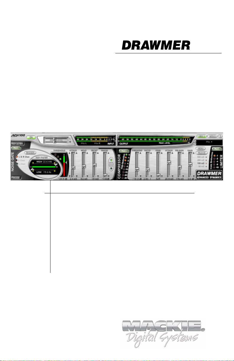
ADX 100
Frequency Conscious Gating, Compression,
Limiting, and Expansion
Plug-in for Mackie Digital Mixers
®
™
Page 2
Iconography
This icon identifies a description of how to
perform an action with the mouse.
This icon identifies a description of how to
perform an action from the console.
This icon will lead you to some further
explanations of features and practical tips.
This icon marks information which is very
important, so please make sure you have a read.
“Mackie” and the “Running Man” figure are trademarks or
registered trademarks of Mackie Designs Inc. All other brand
names mentioned are trademarks or registered trademarks of
their respective holders, and are hereby acknowledged.
Part No. 820-253-00 Rev. A 03/2001
© 2001 Mackie Designs Inc. All Rights Reserved.
2
Drawmer ADX-100
Page 3

Contents
Iconography----------------------------------------------------------------- 2
Introduction---------------------------------------------------------4
About Drawmer Advanced Dynamics ---------------------------------- 4
About the D8B UFX Card ------------------------------------------------- 4
About the Drawmer ADX-100 Plug-in -----------------------------------5
Let’s Get Started ---------------------------------------------------6
Requirements --------------------------------------------------------------- 6
Authorizing the Plug-in --------------------------------------------------- 6
Unlock Procedure ---------------------------------------------------------- 7
Configuring the Plug-in --------------------------------------------------- 8
Using the ADX-100 plug-in-------------------------------------- 10
Front Panel Overview ---------------------------------------------------- 10
Global Controls ------------------------------------------------------------ 11
Noise Gate-------------------------------------------------------------------13
Expander -------------------------------------------------------------------- 17
Compressor/Limiter ----------------------------------------------------- 19
Saving, Loading and Resetting a Preset ------------------------------ 22
Automation and Snapshot Control --------------------------- 25
Dynamic Real Time ------------------------------------------------------- 25
Dynamic Off-line --------------------------------------------------------- 25
FX Routing --------------------------------------------------------- 26
The Plug-in Configuration Window ----------------------------------- 26
Stereo Plug-in Routing--------------------------------------------------- 27
Inserting a Plug-in into a Channel ------------------------------------- 28
Using an Aux Send with a Plug-in -------------------------------------- 29
Send the Input Signal to the Aux Bus --------------------------------- 29
Pre-Fader and Post-Fader Auxiliary Sends --------------------------- 30
The FX Return Channel --------------------------------------------------- 31
Note: Any future revisions of this guide will be available for
viewing and downloading from our website: www.mackie.com.
User’s Guide
3
Page 4

Introduction
Thank you for purchasing the Drawmer ADX-100 plug-in. It is
one of the exciting new family of 24-bit plug-ins for the D8B,
specifically designed for the new Mackie Universal Effects (UFX)
card.
The ADX-100 plug-in utilizes 24-bit digital processing power to
create a multitude of classic Drawmer dynamic effects for the
D8B, the first mixing console in the world to incorporate
Drawmer dynamics.
About Drawmer Advanced Dynamics
The name Drawmer is synonymous with professional signal
processing in recording studio, broadcast, and live sound
reinforcement environments. The company, which is based in
Yorkshire, England was founded by Ivor Drawmer in 1981. With
twenty years of experience designing dynamics processors, Ivor
Drawmer's products are world renowned among mastering
engineers and anyone with an appetite for high-quality noise
gates and compressors.
About the D8B UFX Card
The UFX card provides robust processing power for computationheavy plug-ins. The UFX card is a 4-in/4-out architecture, which
means it can support four mono, two mono and one stereo, or
two stereo sends simultaneously. Up to four UFX cards can be
installed in the D8B, allowing up to sixteen simultaneous singlechannel effects, eight stereo plug-ins, or combinations thereof.
Note: It is recommended that you increase the D8B’s memory if you install
more than one UFX card. Memory upgrade instructions are supplied with each
card.
4
Drawmer ADX-100
Page 5
About the Drawmer ADX-100 Plug-in
The ADX-100 includes Drawmer’s industry-standard frequency
conscious gating, expander, and compressor/limiter. Use the
plug-in during tracking and it may very likely be the only effect
you will use regularly between the microphone and the recording
medium. This advanced dynamics processor will particularly
appeal to engineers recording highly dynamic instruments such
as a real drum kit. The ADX-100 is a stereo in/stereo out plugin. Gate triggering can utilize either mono or stereo outputs. The
ADX-100 can be easily inserted before the D8B’s master outs for
stereo program mastering.
The ADX-100 plug-in will make the D8B an even more powerful
modern music production tool.
User’s Guide
5
Page 6
Let’s Get Started
Requirements
• One or more Mackie UFX cards
• Mackie Real Time OS 3.0 Software
• Plug-in Software
We will assume you have successfully installed a Mackie UFX
card and Mackie Real Time OS 3.0 software upgrade. If you have
encountered problems with the installation of hardware or
software please see their associated user guides or contact
Mackie support (www.mackie.com).
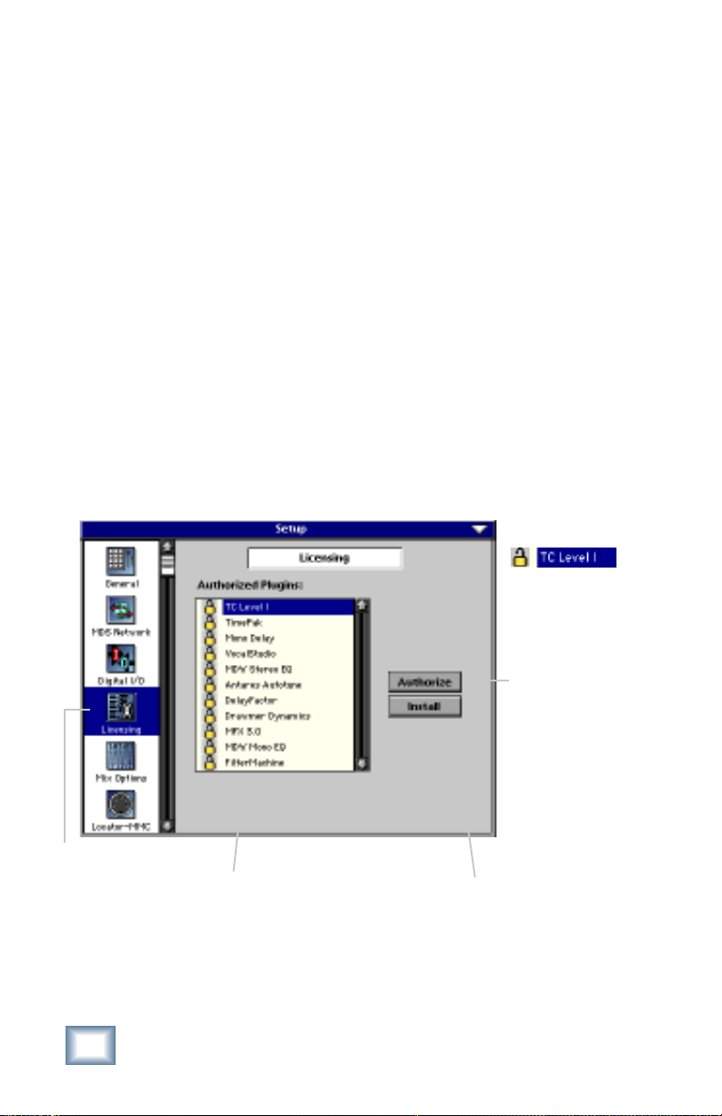
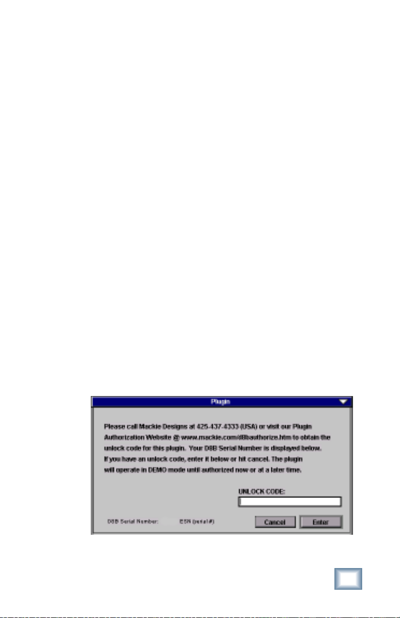
Authorizing the Plug-in
If you have D8B v 3.0 b206 or greater, the plug-in is already
installed on the D8B hard drive, however an authorized unlock
code must be entered to unlock the plug-in for normal operation.
An Unlocked
plug-in
LICENSING
6
1234-5167-89D1
D8B Electronic Serial Number (ESN)
Drawmer ADX-100
AUTHORIZE
D8B SETUP screen’s
LICENSING window
Page 7
Unlock Procedure
1. Locate your D8B’s Electronic Serial Number (ESN). This
is displayed at the bottom of the Licensing window
which is accessed from the Setup screen. The 12-digit
ESN is made from numbers 0–9 and letters A–F. It is
unique to the D8B processor, and is not the serial
number label on the rear of the control surface or CPU
chassis.
2. You will also need your plug-in’s serial number which is
printed on the floppy disk label.
3. To obtain the unlock code, have the ESN and plug-in
serial number ready. Then you have two options:
• Log on to the Mackie plug-in authorization web page:
(http://www.mackie.com/d8bauthorize.htm)
or
• Telephone Mackie Tech Support at 800-258-6883.
4. When you have obtained an unlock code, open the D8B
Setup window, and click Licensing.
5. With your plug-in highlighted in the Licensing window,
click Authorize, and enter your unlock code in the
UNLOCK CODE box. Click Enter, and enjoy your newly
expanded console.
User’s Guide
7
Page 8
Configuring the Plug-in
After booting the D8B, you must assign the plug-in to a UFX
card. See “FX Routing” on page 26 for more details.
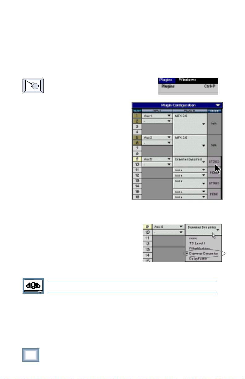
Assign the Plug-in to a UFX card
1. Click the Plugins menu and select
Plugins, (or Ctrl+P on the
keyboard).
2. In the Plugin
Configuration window,
locate the card slot
that contains the UFX
card you wish to assign
to.
3. In the MODE column,
click the Mono/Stereo
toggle button and set it
to STEREO.
4. In the PLUGIN column,
select Drawmer Dynamics from the drop-down menu.
Note: A plug-in can also be loaded from the Setup section on the console.
8
Drawmer ADX-100
Page 9
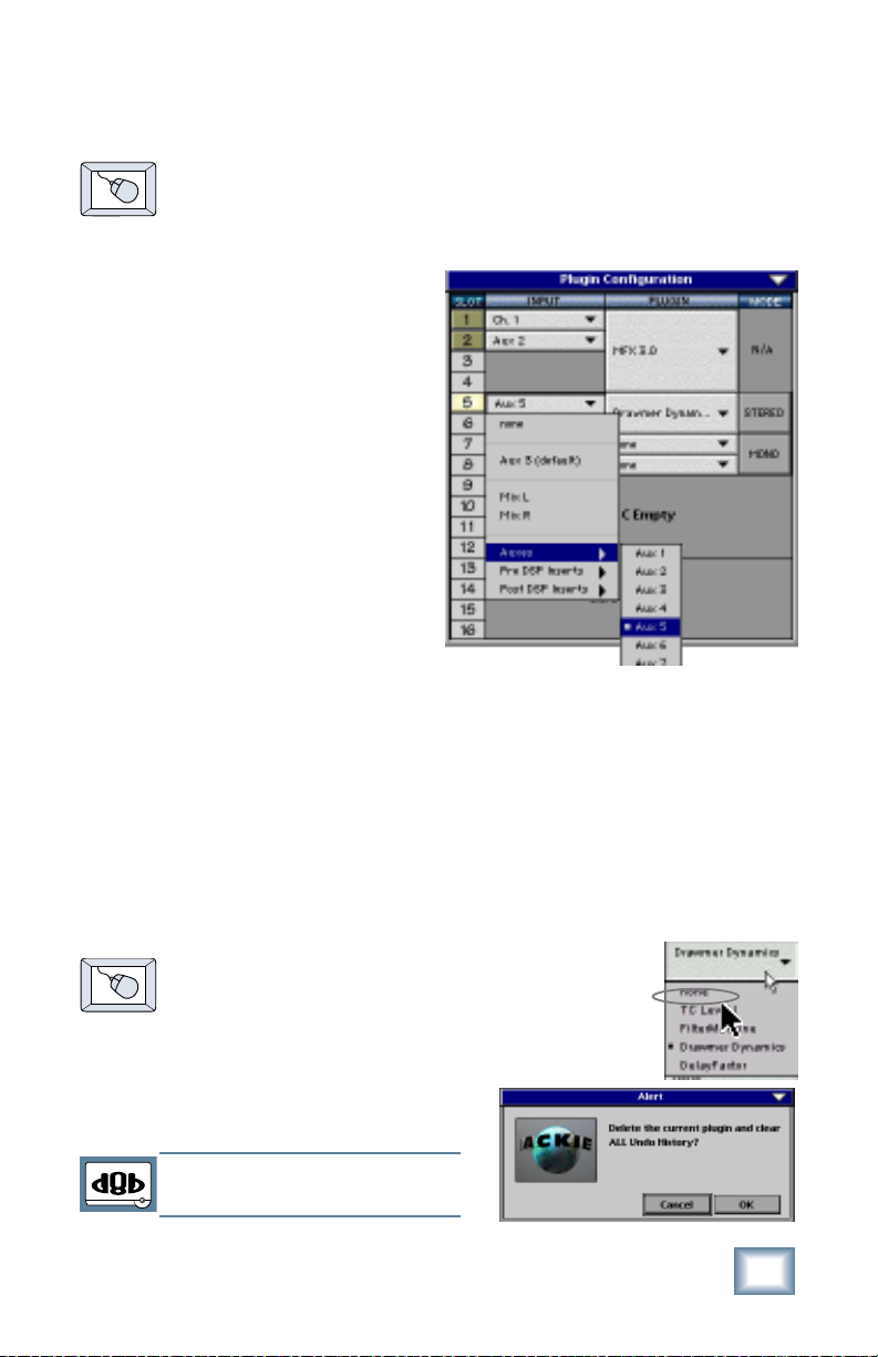
Assign an Input Source to the plug-in
• Click the plug-in’s INPUT menu button to select an input
source. In the example below, we have chosen the Aux 5
Bus as the input to the plug-in installed in slot 5.
When a plug-in is fed from
an aux bus, its output
appears on the FX Return
channels (faders in the
EFFECTS bank). The return
channel is determined by the
slot number and whether the
effect output is mono or
stereo. For example, a
reverb with a mono input
and stereo output that is
installed in Slot 5 has its
outputs on FX 5 and FX 6.
Note: The default state for
all FX channels is MUTE.
You won’t hear the effect
until you unmute its FX
return channel(s).
A plug-in can also receive its input from a channel pre- or postDSP insert or the main stereo left and right Bus insert. When a
plug-in is inserted “in line” in this manner, its output is routed
directly back into the channel. See “FX Routing” on page 26 for
more details, especially in regards to stereo routing.
Removing the Plug-in
1. Select none from the associated Plugin
drop-down assignment menu.
2. Click OK in the Alert dialog box.
Note: A plug-in can also be deleted
from the Setup section on the console.
User’s Guide
9
Page 10
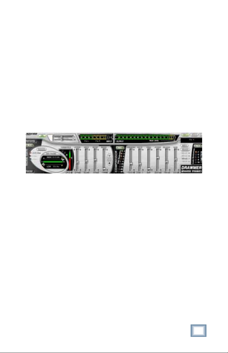
Using the ADX-100 plug-in
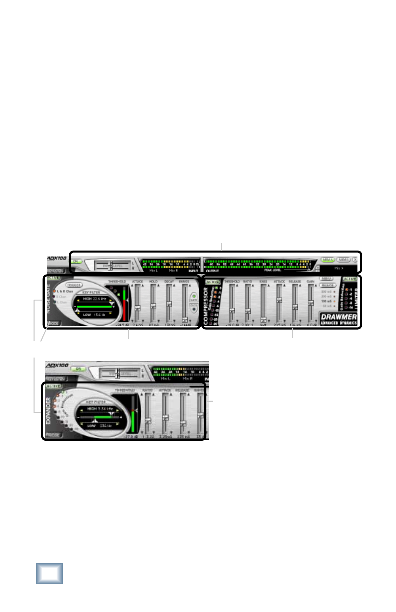
Front Panel Overview
The ADX-100 has four main sections:
Global Controls (see page 11)
Noise Gate (see page 13)
Expander (see page 17)
Compressor/Limiter (see page 19)
Global Controls
Toggle Display
10
Noise Gate
Drawmer ADX-100
Compressor/
Limiter
Expander
Page 11

Global Controls
These controls at the top of the GUI include:
• Input level sliders
• Input/output meters
• Left and right (stereo) input source drop-down menu
• Memory A and B select buttons
• Preset select/display
• Menu button
Input Level
Slider
Meter Displays
(In/Out)
Aux 6
Stereo Input Source
Drop-down Menu
Preset Selection
& Display
Effect On/Off
Button (upper
left of the GUI)
Memory A/B
Buttons
Menu
Button
Hide Plug-In
Window Button
Click in the display for
drop-down preset list.
Note: The Input Source can be set from either the plug-in GUI or the Patch
Configuration Window.
User’s Guide
11
Page 12

Input Level Sliders
The input level sliders range from –13.75 dB to +18 dB.
Input Select
Assign the ADX-100’s stereo inputs and outputs from any of the
DB8’s pre or post inserts, or auxiliary send buses.
Menu Button
The pull-down menu button enables familiar D8B functions such
as undo, redo, load, save, reset, cut, copy, and paste.
Input and Output Meters
Aux 6
The Input Meters show the signal level after the input level
controls, so the OL indicator always warns of an actual overload.
The OL indicator remains on for 1 second following an input
overload. The Output Meters show the ADX-100’s output levels.
The level is controlled by the setting of the gain slider in the
compressor section.
Minimize Button
The small ‘x’ button at the top right will hide the plug-in
window, while the plug-in still remains loaded and active.
Preset Selection and Display
Toggle the up/down arrows to select from your own saved user
presets. You can also click directly in the display for the preset
drop-down list.
On/Off Button
Globally enables or disables the ADX-100. Signals pass through
the disabled ADX-100 dry and at unity gain.
Memory A/B
Memory A and Memory B are two separate storage banks that
let you temporarily store variations of settings. This is handy for
quickly referencing and comparing sounds while you are
creating edits.
12
Drawmer ADX-100
Page 13
Active
Button
(fonts
are white
when enabled)
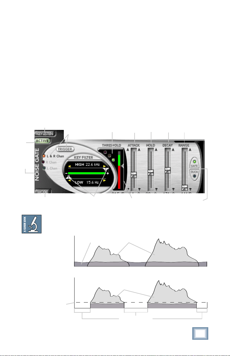
Noise Gate
The ADX-100 Noise Gate with variable threshold level is
extremely effective in reducing background hiss and noise
during portions of a program with no signal. The ADX-100 also
has unique High-Pass/Low-Pass key filters, comprehensive
envelope control, and ultra-fast attack time. The gate works by
muting the corresponding channel when no signal is present, or
when the signal level falls below the gate threshold detection
level. Normally the gate level will be set below the lowest
program level so that it will pass all program material.
Trigger Button
Key Listen
Button
(L&R Channel,
R Channel or L
Channel.
Gate/Duck
Indicators
Attack
Slider
Hold
Slider
Decay
Slider
Range
Slider
Mode Toggle
(Noise Gate/
Expander)
Input Signal
Output Signal
Gate
Threshold
Level
Level
Level
High/Low
Frequency Key
Filters
Noise Floor
Time
Time
Threshold
Slider &
Meter
Audio Signal
Audio Signal
Muted Signal
User’s Guide
Gate/Duck
Tog gl e
13
Page 14

Trigger Button
This toggles the trigger source
between left and right channels,
right channel only, and left
channel only.
Use Right or Left Channel
as external key source
input. An external audio
source may be used to
control the gate action making it possible to gate one sound
according to the dynamics of another independent signal.
Key Listen (Noise Gate/Expander)
When this switch is set to Key Listen, the effect of the key
filters on the program material is heard at the output. In normal
operation (Key Listen Off), the filters only affect the way the
Noise Gate responds to the incoming program material—they do
not have a direct effect on the output signal e.g. try getting a
long sustained ‘strings’ sound with a highhat signal...
Active Button
The Active button enables the Noise Gate. The Active button
(when off) routes the input signal past the noise gate module
without processing.
Key Filter (Noise Gate/Expander)
The Low-Frequency filter is variable from 15.6Hz to
22.6kHz and works by severely attenuating frequencies below
the cut-off frequency selected.
The High-Frequency filter is variable from 15.6Hz to 22.6kHz.
This filter attenuates the frequencies above the selected cut-off
value. When both filters are set, the range between the two
settings is allowed to pass as through a band-pass filter.
Note: Any side-chain filtering which implements high-frequency attenuation will
also cause a slight delay in the time the gate takes to trigger. Under most circumstances this will be quite imperceptible, but when transient sounds are being
processed with the high-frequency control set to a very low value, some degradation of the attack transient may become apparent. For this reason, always set the
high-frequency control to the highest possible value practicable when processing
percussive sounds.
14
Drawmer ADX-100
Page 15

Gate/Duck Indicators
These three LEDs indicate the action of the Gate and Duck
processors. When Gate is selected, the green LED is lit when the
Gate is open. When the signal falls 3 dB below the Threshold,
the green LED turns off and the yellow LED turns on. When the
signal level falls 40 dB below the Threshold, the yellow LED
turns off and the red LED turns on, indicating the signal is fully
gated.
When Duck is selected, the red and green LEDs work in reverse.
When the signal is above the Threshold, the red LED is on.
When the signal falls 3 dB below the Threshold, the red LED
turns off and the yellow LED turns on. When the signal level
falls 40 dB below the Threshold, the green LED turns on,
indicating the signal is unaffected by the Ducker.
Threshold
This sets the level below
which gating starts to take
place and may be set in the
range –63.5 dB to 0 dB. For
normal noise removal
applications, it is normal to
set the Threshold as low as
possible without spurious
triggering occurring, so that none of the desired signal is lost.
Attack
This control determines how quickly the gate opens, and is
variable from 20 µs to 1.1 seconds. The fastest Attack time
ensures that the gate does not clip the leading edge of extremely
fast transients. Tip: Sometimes when gating loud low-frequency
signals, a small pop is heard when the gate opens. This can be
remedied by setting the Attack to 0.5 or 0.6 ms.
Hold
This determines the amount of time the gate is held open after
the signal falls below the Threshold. It is variable from 5.0 ms to
4.74 seconds. This helps to prevent spurious re-triggering when
using fast attack times, but is also instrumental in creating the
classic gated reverb sound often applied to drums.
User’s Guide
15
Page 16

Decay
Determines the rate at which the gate closes, once the signal
has fallen below the Threshold and the Hold time has expired.
Variable from 5 ms to 5.032 seconds.
Range
This sets the amount of attenuation applied to the input signal
when the gate is closed, variable from 0 dB to –144 dB. This
enables the gate to be used to remove unwanted signals entirely,
or simply to attenuate unwanted signals which are too loud.
Tip: When first attempting a gating implementation, the most
typically used parameters are threshold and range, which offer
the most interplay.
Gate/Duck
Switches from normal Gating to Ducking. Probably the most
common form of Ducking is that used by radio announcers,
whereby the volume of the music being played is dropped,
enabling them to speak over it. Ducking a stereo track with a
mono voiceover will require two ADK-100 modules (one per
track), with both L/R triggered by the voiceover audio channel.
Mode Button
Switches between Noise Gate and Expander displays.
16
Drawmer ADX-100
Page 17

Expander
One of the problems in using compression is that maximum
system gain occurs during extremely quiet passages or during
pauses, resulting in an increase in background noise, the degree
of which depends on the amount of compression being used. The
accepted way of dealing with this problem is to include a
separate expander section in the compressor. This expander
section has its own threshold control so that a low-level gating
action may be applied to keep pauses clean. But the problem
with simple expanders is that, even when properly set up, they
may unwittingly process low-level sounds, as they have no
means of identifying them from noise. On a vocal track, for
example, this can lead to the starts or endings of words being
accidentally removed, especially if the singer has a wide
dynamic range. The ADX-100 Expander has separate attack and
release parameters to help negate this unwanted effect.
Active
Button
(font is
white
when enabled)
Gain Reduction Meter
Ratio
Slider
Attack
Slider
Release
Slider
Range
Slider
Mode Toggle (Noise
Gate/Expander)
Threshold Slider
& Meter
Active Button
The Active button enables the Expander. The Active button
(when off) routes the input signal to the output with no
processing.
Threshold
This control sets the level below which expansion starts to take
place and may be set in the range –63.5 dB to 0.0 dB.
User’s Guide
17
Page 18

Ratio
When expansion takes place, the Ratio determines the amount
of expansion to be used. The ratio slider sets the expansion ratio
from 1:1 to 1:123
Range
Sets the amount of attenuation applied to the input signal when
the expander is triggered, variable from 0 dB to –63 dB. This can
be used to prevent excessive expander activity and improve
transparency.
Attack
The Attack time sets the rate at which the expander will
respond to input signals that exceed the threshold level. This
may be set in the range 0.10 ms to 100 ms.
Release
Release time is variable and may be set from 20 ms to 997 ms.
Percussive material with little or no reverb is generally treated
using a faster release setting, whereas material with slow
decays or a significant amount of added reverberation will
usually respond better to a longer release setting.
Mode Button
Switches between Noise Gate and Expander displays.
18
Drawmer ADX-100
Page 19

Compressor/Limiter
Compressor
A compressor is
traditionally used to fit a
large signal into a small
space, especially in a
situation where the dynamic range of the original audio signal is
larger than the electronic reproduction equipment will accept
(broadcast engineers appreciate this very much). Compression
might also be thought of as being one of the most important
tools used in both recording and mixing.
Automatic gain makeup is active at all times. This adjusts the
compressor output level to compensate for the amount of gain
reduction. This reduces the need to readjust the compressor gain
after changing ratio, threshold, or knee settings.
Limiter
Limiting is basically extreme compression. The limiter is set to
affect only signals above a certain level. This is particularly
useful for limiting peaks that would otherwise send the signal
beyond the capacity of the equipment being used. Limiting has
become very popular when using a digital recorder because
peaking a digital signal sounds like a car wreck. When used in
this fashion, thresholds are set at around –2 db to prevent the
signal from clipping.
10
l
e
v
e
L
l
a
n
ig
S
t
u
p
t
u
O
Threshold
Level
1:1
No Compression
2:1
Compression
Limiting Threshold
0
Input Signal Level
10
Active Button
The compressor and limiter have their own Active buttons. The
compressor Active button (when off) routes the input signal
directly to the limiter, with no processing or gain.
User’s Guide
19
Page 20

Output Level
0 dB
-6 dB
-16 dB
-24 dB
-36 dB
-48 dB
-60 dB
-42 dB -34 dB -60 dB -26 dB -18 dB -14 dB -10 dB -4 dB 0 dB
1:1
2:1
4:1
8:1
20:1
:1
8
Threshold
This control sets the level
above which compression
starts to take place and
may be set in the range
Attack Time
Threshold
Level
–63.5 dB to 0.0 dB.
Ratio
Input Level
When compression takes
place, the Ratio
determines the amount of compression to be used. The ratio
slider sets the compression ratio from 1:1 to 20.3:1.
Knee
The Knee parameter is variable between Hard and Soft Knee
operation. In general, the Soft Knee mode provides the least
obtrusive gain control and is often the preferred setting when
treating finished mixes.
Attack
Attack Time Release Time
The Attack time sets the
rate at which the
compressor will respond
to input signals that
exceed the threshold
level. This may be set in
the range 0 to 100 ms.
Release
Sets the rate at which the
system gain returns to
normal after the input
signal level has fallen below the threshold. Release time is
variable and may be set from 33 ms to 3.66 s.
20
Drawmer ADX-100
Page 21
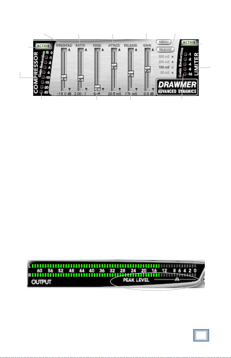
Threshold Slider
Active
Button
(font is
white
when enabled)
Ratio Slider
Attack Slider
Gain Slider
Limiter Release
Time Presets
Active
Button
(font is
white
when enabled)
Gain Reduction Meter
Knee Slider
Release Slider
Gain Reduction Meter
Gain
When compressing, the input signal is attenuated as a normal
consequence of the gain reduction action of the compressor
responding to the signal dynamics. As a result, gain is usually
added to the compressor output to bring the signal level back up to
program level. The ADX100 uses automatic gain makeup, which is
applied in response to Threshold, Ratio, and Knee settings. If input
signals are at –6 dB, then the output volume stays the same as the
ratio is increased. Input signals that fall below –6 dB will increase
in volume when the ratio is increased. It should only be necessary
to make fine adjustments to control gain activity. The Gain control
has a range from +15.7 dB to –16 dB.
Limiter Release
This button toggles between preset release times for the Limiter.
Release presets are 500, 200, 100 and 50 ms.
Peak Level
This small slider sets the level at which the Limiter will engage
corresponding with the output meter directly above. Peak Level is
adjustable from –0.0 dBFS to –15.88 dBFS.
Gain Reduction Meter
The compressor and limiter each have a Gain Reduction Meter,
which indicates the amount of attenuation applied by the
compressor and limiter. The higher the signal is above the
threshold, the greater the gain reduction.
User’s Guide
21
Page 22
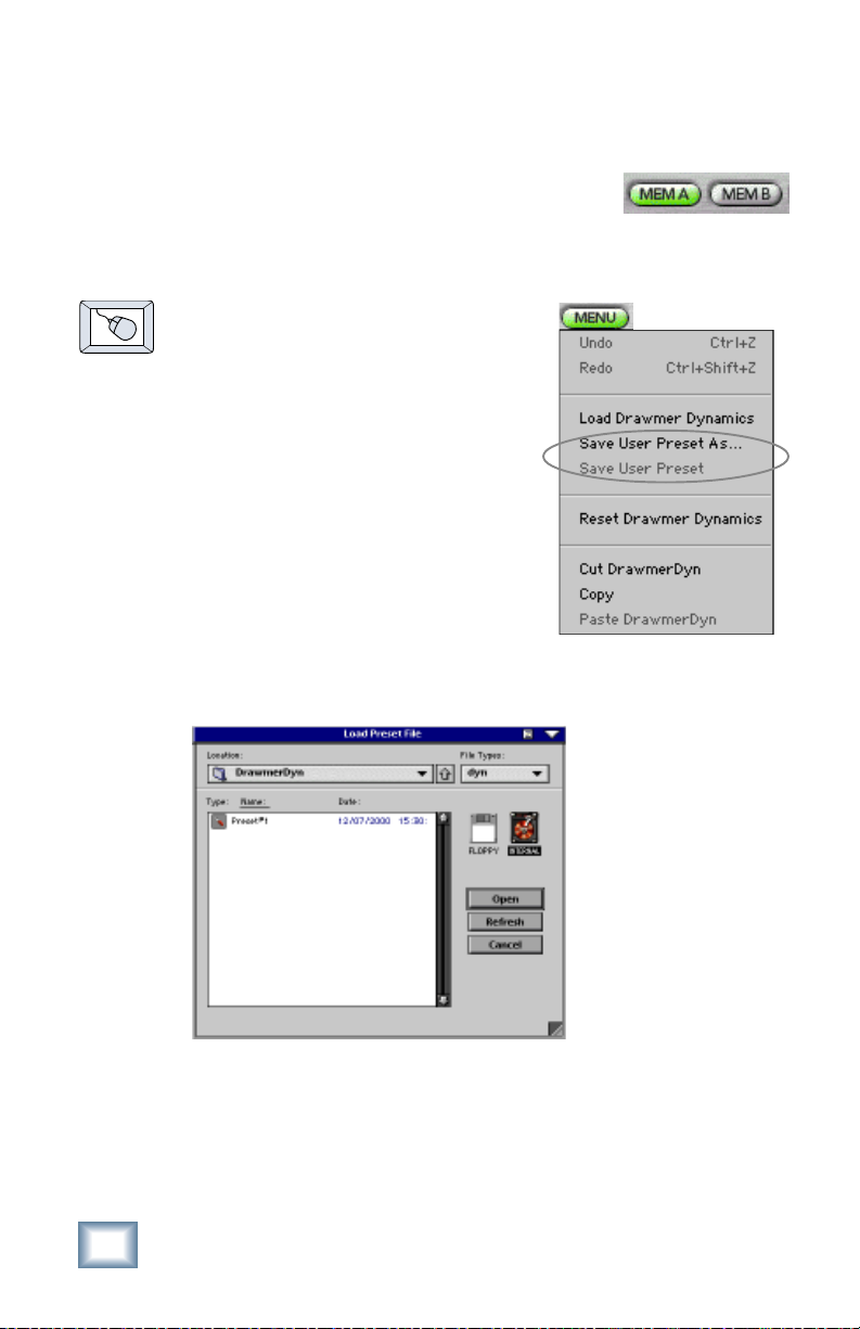
Saving, Loading and Resetting a Preset
ADX-100 settings can be saved and recalled
from the hard drive. You can save and load files
from either Memory A or Memory B.
To Save a Preset:
1. Click and hold on the MENU
button.
2. Select Save User Preset to
overwrite the file currently
opened.
3. Select Save User Preset As to
save to a new file name. The
Save Preset File As dialog box
appears.
4. A default name for the preset is
automatically displayed, such
as Preset#1. If you want to rename it, simply type in the
name you want, using up to 32 characters.
22
A new sub folder can
be easily created to
help organize custom
patches.
5. Select INTERNAL (default hard drive) or FLOPPY.
6. Click Save to complete the operation.
Drawmer ADX-100
Page 23

To Load a Preset:
1. Click MEM A or MEM B to choose the
memory location from which to load
the file.
2. Click and hold the MENU button.
3. Select Load Drawmer Dynamics
to open a file. The Load Preset
File dialog box appears.
4. Click INTERNAL if the file is on
the internal drive, or click FLOPPY if the file is on a
floppy disk.
5. Select the preset you want to load.
6. Click Open load the selected preset.
You can also load a
patch from the Preset
Display.
User’s Guide
23
Page 24

To Reset The Preset:
Reset will reload the previous patch.
1. Click and hold on the MENU
button.
2. Select Reset Drawmer
Dynamics.
To Cut Preset Settings:
1. Click and hold on the MENU
button.
2. Select Cut DrawmerDyn.
The current settings are temporarily
stored in the clipboard memory in case you
want to paste them to a new preset. The plug-in also reverts to
its default state (it is reset).
To Copy Preset Settings:
1. Click and hold on the MENU button.
2. Select Copy.
The current settings are temporarily stored in the clipboard
memory in case you want to paste them to a new patch.
To Paste Preset Settings:
1. Click and hold on the MENU button.
2. Select Paste DrawmerDyn.
The current settings are replaced with the setting in the
clipboard memory.
24
Drawmer ADX-100
Page 25

Automation and Snapshot Control
Dynamic Real Time
To write automation on a loaded plug-in:
1. Engage AUTO TOUCH.
2. Engage ALL, disengage
BYPASS, and send
timecode to the console –
the POSITION readout will change to show TC is being
received.
3. Move a parameter or recall a patch (user or factory
preset).
Subsequent edits to any recorded automation moves may be
performed in the Mix Editor. Enable the channel view by clicking
the Channel View button, then choose the plug-in you wish to
view from the page drop-down
menu. This will display a list
of available channel and plugin automation tracks on a
parameter basis.
Note: Parameters can be controlled from either the GUI plug-in graphic parameters (using a mouse to modify the parameters) or via the VFD V-Pots and
SELECT buttons (with the plug-in parameters called up on the VFD readout).
On The Console
Dynamic Off-line
To write a snapshot on a loaded plug-in:
♦
Use the Event Automation Track, available under the
Window Menu as ‘Event Track’, to load plug-in user
(previously stored) or factory preset patches, at a
specific time during automation playback.
General Note:
Plug-in settings are recalled as part of a console Snapshot, but may also be recalled as Presets (patches). If you are recalling snapshots and presets, be aware
that one may override the other.
User’s Guide
25
Page 26

FX Routing
The Plug-in Configuration Window
Card Slot Column
Plug-in
display toggle
Input Channel
Assignment Dropdown Menu Button
Card A
Card B
Card C
Card D (no
card installed)
Input Source Assignment Column
Plug-in Assignment Column
Close Window
Stereo/Mono
Mode Column
Stereo/Mono
Toggle Button
26
Drawmer ADX-100
Page 27

Stereo Plug-in Routing
If the plug-in has a stereo input as well as stereo output,
typically it will be fed from two Aux buses and returned to a pair
of FX return channels. In the diagram below, Aux 1 and Aux 2
feed the plug-in in stereo, and its output is returned to FX 1 and
FX 2. If the plug-in has a stereo input, it is permissible to send
the same aux bus to both inputs.
FX Channels 1&2
(channels 49&50)
Stereo Input
(Aux 1 & 2)
Note: When an FX Channel Assignment light
is lit, the assigned plug-in is open and visible
on the main mixer screen.
Stereo plug-in
User’s Guide
27
Page 28
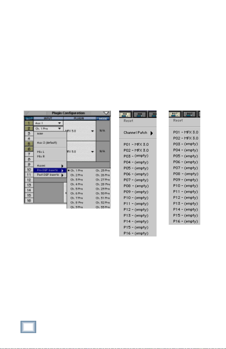
Inserting a Plug-in into a Channel
A pre- or post-DSP channel insert can also be used as the input
source for a plug-in. When a channel insert point is selected, the
plug-in output returns to the channel. The FX return path is
disconnected, although the plug-in output is still displayed on
the FX return channel meter.
A plug-in channel insert assignment can be made from the
Plugin Configuration window, or from a drop-down menu from
the mixer screen.
Plugin Configuration Window
Post-DSP Drop-down
Pre-DSP Drop-down
This assignment can also be made from the control surface and
VFD by holding in the desired channel’s SELECT button for two
seconds, then paging over to Plug Pre or Plug Post, selecting
the input source, then selecting the desired plug-in slot from the
follow-on menu.
28
Drawmer ADX-100
Page 29

Using an Aux Send with a Plug-in
♦
Click on the associated INPUT menu button and select
an aux input source. In the example below, we have
chosen the Aux 5 Bus.
Send the Input Signal to the Aux Bus
1. Send a signal to a D8B mixer input
channel (MIC/LINE or TAPE IN).
2. Assign the input channel V-Pot/GUI
Control Pot to an aux Send. We have
chosen AUX 5 according to the
example above.
3. Use the AUX 5 control to
adjust the input level to the
plug-in.
Remember to select an aux send before using the V-pot or GUI
Control Pot on the mixer input channel (MIC/LINE or TAPE IN).
User’s Guide
GUI Control
Pot Assigned
to AUX 5
29
Page 30

You will see the plug-in’s input meter become active as you raise
the mixer input channel’s Aux send.
Set the plug-in input/output signal levels as you would with any
effect, so the meter reaches its upper-most range every so often
(always trust your ears first). This can be accomplished from the
console or GUI.
Pre-Fader and Post-Fader Auxiliary Sends
Normally, effect sends are post-fader, so the signal sent to the
effect follows the program level in the mix. Occasionally you
may wish to feed an effect from a pre-fader source so that the
signal level from the aux control is independent of the channel
fader position. Aux sends are selectable pre- or post-fader
globally (all Aux 1’s for instance) from the Mix Options screen in
the Setup window, or individually on a channel-by-channel basis
either from the channel strip or the Fat Channel.
In the channel strip, Alt-click the Aux Send level
indicator to toggle between pre-and post-fader operation.
Post-fader is indicated by a red bar, pre-fader is indicated
by a yellow bar.
Channel Strip
30
In the Fat Channel,
clicking on the small
indicators below the
Aux knobs toggles
between pre- and postfader operation. Yellow
indicates pre-fader,
post-fader is indicated
by the background
color.
Fat Channel
Drawmer ADX-100
Page 31

The FX Return Channel
♦
Switch the D8B Bank Select to
EFFECTS (49–72) and bring up
faders one and two (channels 49 and
50). You will also see meter activity
associated with these channels.
FX Channels 1&2
(channels 49&50)
Stereo plug-in
The Plug button
toggles between
Windows menu
buttons and FX
buttons (lower
left on the D8B
mixer screen).
Plug-ins button opens the Patch
Configuration window (or
P
on the keyboard)
Here the Delay Factor plug-in is
selected for display.
Ctrl-
User’s Guide
31
Page 32

®
™
©2001 Mackie Designs Inc. and Drawmer Advanced Dynamics.
All Rights Reserved.
Part No. 820-253-00 Rev. A 04/2001
 Loading...