

Page 1
DRAWMER
CMC3
MONITOR CONTROLLER
CONTENTS
Warranty
Safety Consideration
Radio Frequencies Statement
. . . . . . . . . . . . . . . . . . . . . . . . . . . 3
. . . . . . . . . . . . . . . . . . 3
. . . . . . . . . . . . . 3
Chapter 1 - Introduction
Introduction
Installation
Power Connection
Security
Audio Connection
Typical Connection Guide
Chapter 2 - Control Description
Control Description
Mix Checking Tips
Chapter 3 - General Information
If a fault develops
Contacting Drawmer
Specification
Block Diagram
. . . . . . . . . . . . . . . . . . . . . . . . 4
. . . . . . . . . . . . . . . . . . . . . . . . . 6
. . . . . . . . . . . . . . . . . . . . . 7
. . . . . . . . . . . . . . . . . . . . . . . . . . . . 7
. . . . . . . . . . . . . . . . . . . . . 8
. . . . . . . . . . . . . . . . 9
. . . . . . . . . . . . . . . . . . . . . . . . . . . . 10
. . . . . . . . . . . . . . . . . . . . 16
. . . . . . . . . . . . . . . . . . . . 19
. . . . . . . . . . . . . . . . . 19
. . . . . . . . . . . . . . . . . . . . . . . 19
. . . . . . . . . . . . . . . . . . . . . . 20
Page 2

DRAWMER
This manual i s copyrighted © 2018 by Drawm er El ectronics Ltd. W ith al l rights reserved. Under copyrig ht
laws, no part of this publ icati on may be reproduced, transm itted, stored in a retrieval system or trans lated
into any language in any f orm by any means, mechanical, optical, electronic, recordi ng, or otherw ise,
without the w ritte n perm is sion of Drawmer Electr onics Ltd.
2
COPYRIGHT
Page 3
ONE YEAR LIMITED WARRANTY
Drawmer Electronics Ltd., warrants the Drawmer CMC3 Monitor
Controller to conform substantially to the specifications of this
manual for a period of one year from the ori ginal date of purchase
when used in accordance with the specifications detailed in this
manual. In the case of a valid warranty claim, your sole and exclusive
remedy and Drawmer’s entire liability under any theory of liability will
be to, at Drawm er’s discretion, repair or replace the product without
charge, or, if not possible, to refund the purchase price to you. This
warranty is not transferable. It applies only to the original purchaser
of the product.
For warranty servic e please call your local Drawmer dealer.
Alternatively call Drawmer Electronics Ltd. at +44 (0)1709 527574.
Then ship the defective product, with transportation and insurance
charges pre-paid, to Drawmer Electroni cs Ltd., Coleman Street,
Parkgate, Rotherham, S62 6EL UK. Write the RA number in large
letters i n a prominent position on the shipping box. Enclose your
name, address, telephone number, copy of the original sales invoice
and a detailed description of the problem. Drawm er will not accept
responsibility for l oss or damage during transit.
This warranty is voi d if the product has been damaged by misuse,
modification, unauthorised repair or installed with other equipment
that proved to be faulty.
THIS WARRANTY IS IN LIEU OF ALL W ARRANTIES, WHETHER
ORAL OR WRITTEN, EXPRESSED, IMPLIED OR STATUTORY.
DRA W ME R MAKES NO OTHER WA RRA NTY EITHER
EXPRESS OR IMPLIED, INCLUDING, W ITHOUT LIMITATION,
ANY IMPLIED WARRANTIES OF MERCHANTABILITY, FITNESS
FOR A PARTICULA R PURPOSE, OR NON-INFRINGEMENT.
PURCHASER’S SOLE AND EXCLUSIVE REMEDY UNDER THIS
WARR ANTY SHALL BE REPAIR OR REPLA CEMENT AS
SPECIFIED HEREIN.
IN NO EVENT WILL DRAWMER ELECTRONICS LTD. BE LIABLE
FOR AN Y DIRECT, INDIRECT, SP ECIAL, INCIDENTAL OR
CONS EQUENTIA L DAMA GE S RES ULTING FRO M ANY
DEFECT IN THE PRODUCT, INCLUD ING LOST PROFITS,
DAMAGE TO PROPERTY, AND, TO THE EXTENT PERMITTED
BY LAW, DAMAGE FOR PE RSO NAL INJURY, E VEN IF
DRAWME R HAS BEEN ADVISED OF THE POSSIBILITY OF
SUCH DAMAGES.
Some states and specific countries do not allow the exclusion of
implied warranties or limitations on how long an implied warranty may
last, so the above limitations may not apply to you. This warranty gives
you specific legal rights. You may have additional rights that vary from
state to state, and country to country.
CHAPTER 1
For the USA
FEDERAL COMMUNICATIONS COMMISS ION RADIO
FREQUENCY INTERFERENCE STATEMENT
Thi s equipment has been tested and found to comply with the limits
for a Class B digital device, pursuant to Part 15 of the FCC Rules.
These limits are designed to provide reasonable protection against
harmful interference in a residential installation. This equipment
generates, uses and can radiate radio frequency energy and, if not
installed and used in accordance with the instructions, may cause
harmful interference to radio communications. However, there is no
guarantee that interference w ill not oc cur in a particular installation.
If this equipment does cause interference to radio or television
reception, which can be determined by turning the equipment off an
on, then the user is encouraged to try to correct the interference by
one or more of the following measures:
Re-orient or relocate the receiving antenna.
Increase the separation between the equipment and the receiver.
Connect the equipment into an outlet on a circuit different from that
to which the receiver is connected.
Consult the dealer or an experienced radio/TV technician for help.
Unauthorised changes or modification to this system can void the
users’ authority to operate this equipment.
This equipment requires shielded interface cables in order to meet
FCC class B limit.
For Can ada
CLASS B NOTICE
This digital apparatus does not exceed the Class B limits for radio
noise emissions s et out in the Radio Interference Regulations of the
Canadian Department of Communications.
CLASSE B AVIS
Cet appareil numérique ne dépasse pas les limites de la classe B au
niveau des émis sions de bruits radioélec triques fixés dans le
Règlement des signaux parasites par le ministère Canadien des
Communications.
SAFETY CONSIDERATIONS
DO NOT OPEN. REFER ALL SERVICING TO QUALIFIED SERVICE PERSONNEL.
TO REDUCE RISK OF FIRE/ELECTR IC SHOCK DO NOT EXPOSE T HIS EQUIPMENT TO MOISTURE.
DO NOT ATTEMPT TO CHANGE OR TAMPER WIT H THE SUPPLIED MAINS CABLES.
THERE ARE NO USER REPLACEABLE FUSES W ITHIN EITHER THE C MC3 OR IT’S SUPPLIED
POW ER SUPPLY. IF FOR ANY REASON TH E CMC3 CEASES TO W ORK DO NO T ATTEMPT TO
MEND IT - CONTACT DRAWMER TO ARRANGE FOR A REPAIR/REPLACEMENT.
In the interests of product development, Drawmer reserve the right to modify
or improve specifications of this product at any time, without prior notice.
CAUTION - SERVICING
WARNING
WARNING
WARNING
CMC3 - Monitor Controller
3
Page 4
DRAWMER
CMC3
Monitor Controller
FULLY FEATURED MONITOR CONTROLLER FOR STUDIOS OF ALL SIZES.
PRECISE, COMPACT & AFFORDABLE.
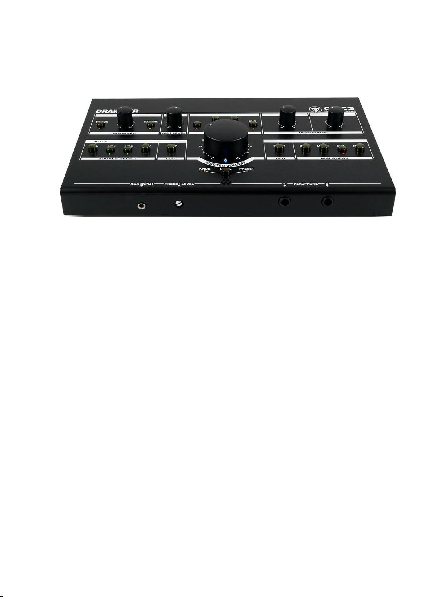
The CMC3 Compact Monitor Controller consolidates the feature sets of Drawmer's
3 most po pular monitor contro llers: W hilst retaining the famed accurate, and
transparent audio quality of the MC2.1, it has the precision and control of the MC3.1
and the low profile, compact design of the CMC2. It is equally at home in a serious
home studio as in a professional recording facility.
Accurate & Transparent
W ith the same Drawmer pedig ree as the MC2.1, the CMC3 circuit is just as
transparent and accurate. It has been designed to remove the limitations that a
passive circuit brings, such as the ability to increase the volume for quiet passages
and improved mix checking, without adding the artifacts that lesser quality active
circuits introduce. You hear exactly what you've recorded!
Precision
The CMC3 supports 3 sets of stereo monitors, plus a dedicated mono speaker/
sub-woofer output, each can be switched individually and simultaneously and in
any order, especially useful for A/B comparisons. You can listen to multiple speakers
with the same sub-woofer, or turn the sub-woofer off altogether.
The volume control utilizes a parallelled custom quad pot for excellent channel
matching and smooth feel, as does the secondary preset volume control on the
front. This provides repeatable calibrated output level for the monitors, so that at
the flick of a switch the engineer can hear the mix at the same predetermined
volume, time after time, without having to meticulously adjust controls.
4
Page 5

Multiple Connections
The CMC3 is very well connected with 4 stereo inputs in total: 1x SPDIF digital input
(24 bit/192kHz), using the same DAC chipset as our established MC3.1 monitor
controller, 2 stereo balanced jack inputs, plus a 3.5mm jack with variable level
control for your Smartphone/MP3 Player.
In addition, it has a 2 pro fessional quality headphone outputs with a separate
amplifier and level control, that provide the same audio quality and mix checking as
the CMC3 does through the speakers. Talkback is also included with internal or
external microphone, level control and audio routing to a dedicated mono output
jack & headphones.
Advanced Mix Checking
The comprehensive mix checking facilities of the CMC3 include dim, mono, phase
reverse, left and right cut as well as an easy access mute switch, allowing you to
check the quality of your recordings: tune into your mix to hear any unwanted artefacts,
test the effectiveness of the stereo mix, check for phase cancellation, listen to the
stereo difference. Features that many monitor controllers lack.
Main Features:
Ultra low noise and transparent circuit design.
•
Source switches can be active in any combination. 4 Inputs in Total - 1x
•
Digital SPDIF (192 kHz / 24 Bit) & 2 on balanced analogue 1/4" jacks & 1
3.5mm Front Panel Aux jack for your Smartphone/MP3.
3x Speakers Plus a Mono Sub can be switched individually & simultaneously
•
or give A/B comparisons.
Timed relay protection on all speaker outputs to prevent power up/down
•
bangs.
Volume can be set via the Variable Front Panel Knob or a Preset Control.
•
Each has parallelled custom quad pots for excellent channel matching and
smooth feel.
2x Headphone Amplifiers with Individual Level Controls with easy access to
•
the jacks on the front.
Front Panel 3.5mm AUX Input & Level Control for connecting MP3 player,
•
smartphone or tablet etc.
Built In Talkback with Level Control, Internal or External Microphone, and
•
Internal Routing to a Mono Output Jack & Headphones.
Comprehensive Mix Checking facilities Include Dim, Phase Reverse and
•
Mono, Left and Right Cut as well as an easy access Mute switch.
Kensington security slot (also called a K-Slot or Kensington lock).
•
Very low profile desktop enclosure with a footprint of just 18x16cm.
•
Stylish and Rugged Enclosure will withstand the knocks of the studio.
•
Designed and manufactured by Drawmer in the UK.
•
CMC3 - Monitor Controller
5
Page 6
DRAWMER
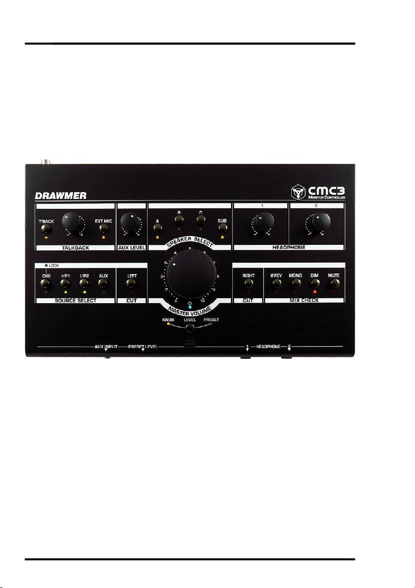
INSTALLATION
The CMC3 is a free standing, desktop unit. We have endeavoured to make the
CMC3 as small as possible without compromising on controls, connections and
above all sound quality. The unit has a footprint of just 27cm x 16cm with controls
on the top, headphone and mp3/phone input on the front and all other connections
on the rear panel.
6
Page 7

POWER CONNECTION
The CMC3 unit will be supplied with an external switching mode power supply that
is capable of 100-240Vac continuous (90-264Vac max) and so should work globally.
We strongly advise that the power supply that has been supplied with the CMC3 is
used, rather than one with the equivalent ratings. In addition, should the power
supply fail for any reason we str ongly advise that you contact Drawm er for a
replacement rather than repairing the unit yourselves. Failure to do either of these
could permanently damage the CMC3 and will also invalidate the warranty.
The power supply can be fitted with 4 interchangeable AC pins for the UK, European,
USA and Australian, though will be supplied with a type that is suitable for domestic
power supply outlets in your country, the others are available upon request. For your
own safety, it is important that you use the correct adapter. The power supply must
not be tampered with or modified.
Before connecting the CMC3 to the power supply ensure that all knobs are
turned off (i.e. fully anticlockwise). A switch next to the d.c. power inlet on the rear
of the unit switches the power on/off.
POWER SWITCH
POWER SUPPLY INLET
SECURITY
To help protect the CMC3 from theft the side has a Kensington Security Slot (also
called a K-Slot) which enables the fitting of hardware locking accessories that can
attach your CMC3 to an immovable object, making the CMC3 more of a challenge for
the potential thieves to steal.
CMC3 - Monitor Controller
7
Page 8

DRAWMER
AUDIO CONNECTIONS
• Interference:
If the unit is to be used where it
mayb e exp o sed to high levels of
disturbance such as found close to
a TV or radio transmitter, we advise
th at th e unit is o p e rate d in a
balanced con fig u ra tio n . T h e
screens of the signal cables should
be co n n ec ted to th e ch assis
connection on the XLR connector as
opposed to connecting to pin1. The
CMC3 co nfo r m s to th e EM C
standard s.
Cable Wiring for TalkBack Output (Mono) to Stereo Distribution
8
• Ground Loops:
If ground loop pro ble m s are
encountered, never disconnect the
mains eart h , but inste ad , tr y
disconnecting the signal screen on
one en d o f each o f t he c able s
connecting the outputs of the CMC3
to the patchbay. If such measures
are necessary, balanced operation
is recom mended.
Page 9

TYPICAL CONNECTION GUIDE
CMC3 - Monitor Controller
9
Page 10

DRAWMER
CHAPTER 2
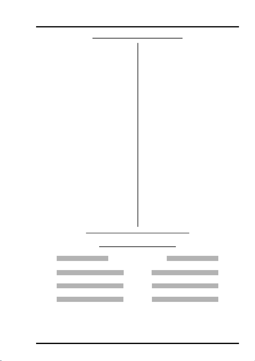
CONTROL DESCRIPTION
As well as a transparent and precise signal path the CMC3 Compact Monitor
Controller incorporates many impressive features which are invaluable to the sound
engineer when listening to and examining the quality of the audio.
1
SOURCE SELECT
Four switches select which of the analogue inputs - I/P1, I/P2 (9) and AUX (1b), and
digital input - DIGI (8), are heard at the Speaker Outputs (10) and Headphones (6b).
Each can be operated individually or simultaneously and in any combination. When
operated simultaneously the individual signals are summed into a single stereo
signal. Note that the CMC3 does not provide individual level trims for the I/P1, I/P2
and DIGI inputs and so any level matching should be applied before it reaches the
CMC3.
The digital DAC converts up to 192kHz/24 Bit and is via SPDIF (8) phono socket
located on the rear. A LOCK led above the switch shows when the signal is strong
and the CMC3 is locked in, if not lit the digital signal should be checked.
An AUX 3.5mm stereo jack input is located on the front panel (1b) to allow easy
access to connect a MP3 player, smartphone or similar audio device. A control
knob (1c) allows the adjustment of the AUX volume to match the system level.
10
Page 11

2
MASTER VOLUME
The Monitor Volume control (2) adjusts the signal level of both stereo channels for
all speaker outputs. The Volume knob affects the volume of the monitors A,B,C and
SUB only and does not have a bearing on any other output such as the headphones
or talkback jack.
A secondary preset volume control on the front edge (2a) provides a repeatable
calibrated output level for the monitors, so that at the press of the switch just below
the main volume knob the engineer can hear the mix at the same predetermined
volume, time after time, without having to meticulously adjust controls. Once the
system is calibrated the predetermined level could be set via a screwdriver to the
maximum listening level, 85dB in the case of TV, film and music, for example, or to
a standard listening level for radio, or even a preferred level for quiet passage. The
level chosen is at the discretion of the operator.
Both the volume knob and preset control circu it designs incorpo rate identical
parallelled custom quad po ten tiometers, for excellent channel matching and a
smooth feel, with a range from Off (-infinity) to +6dB of gain.
Because the circuitry is active it allows for the signal level to be increased, rather
than only attenuated, making subtle problems within the mix (such as noise at low
levels, or unwanted harmonics, for example) more obvious and easier to iron out,
especially during musical passages that would normally be quiet.
Before you can make full effective use of the Volume control it is necessary to
calibrate the entire monitoring system, this allows for accurate level control, as
well as left/right balance throughout the knob’s range. Note that the actual output
levels, including the maximum output level and the position of unity gain (0dB)
around the knob, will alter depending on the calibration of the monitors.
WARNING:
It is recommended that you turn the volume control down to a lower level before
turning the CMC3 off - this is to ensure that a sudden volume increase when
turning on does not damage your speakers or your hearing.
In addition, do not use excessive force at either end of the volume knob - it’s
size would mean that damaging the potentiometer is possible.
Note that on the underside of the CMC3 there are 2 rotary controls that allow the left
and right speaker level of all of the Speaker Outputs (10) to be trimmed. If the input
levels into the CMC3 are very high the operator will find that the optimum location of
the volume knob (i.e. 85dB output level) would be at around 9 o’clock or worse leaving them with only a few degrees of rotation in which to lower the volume. By
adjusting the trims underneath this can be improved to give the preferred listening
level to somewhere more useful, such as the 12 o’clock position. This is especially
useful for those studios who work at high gain levels, allowing them to come into
the CMC3 ‘hot’.
To alter the speaker level trims use a small screwdriver to turn - counter-clockwise
turns the speaker level down, and clockwise up.
CMC3 - Monitor Controller
11
Page 12

DRAWMER
SPEAKER SELECT
3
Four switches select which of the four speaker outputs A, B, C or SUB are heard
(10).
Each switch can be operated individually or simultaneously and in any combination
and is perfect for performing A/B comparisons between various monitor setups. As
the switches do not toggle between outputs when doing A/B comparisons both of
those switches should be pressed at the same time i.e. to compare speakers A
and C, with A active press both the A and C switches to swap the output to C active,
and then again to return to the previous setting - this method can be used between
all four outputs if required.
An additional benefit is derived when using a sub-bass. If the sub-bass is attached
to the SUB/MONO output on the rear of the MC3.1, outputs A and B could deliver the
higher frequencies and allow for A/B (or in this case A+Sub/B+Sub) comparisons
between the two monitor setups by pressing the A and B switches simultaneously
and leaving SUB always active. In addition, a full frequency range monitor could be
attached to C, so, with the C switch active SUB should be disengaged.
4
MIX CHECKING
The Mix Checking section allows the engineer to test various aspects of the mix
withou t having to alter the signal earlier in the chain and potentially effect the
recording, and is a very thorough and versatile checking tool. The switches are
especially useful when used in conjunction with each other.
Phase Reverse: Inverts the polarity of the signal on the Left Channel and is used
primarily to outline any phase problems that may be occurring in the mix/recording
such as phase cancellation, or an unbalanced stereo signal. As the switch is
toggled any phase issues will become more apparent and easier to identify.
Mono: With the switch active both Left and Right stereo signals are combined into
a single mono signal.
It is necessary when testing the audio to not only listen to the signal in stereo but
also in mono. It helps to outline problems in the mix, but also when testing for use
on non-standard applications such as for broadcast or mobile phone.
Dim: W ith the switch active the output level is attenuated by 20dB’s. It enables you
to lower the volume without adjusting any of the settings.
Mute: Cuts the level of both channels and is especially useful in an emergency. If
Left Cut and Right Cut are both active it is just the same as Mute being active.
Note that Mute does not affect the headphones (6a, 6b) in the same way as it does
the speakers (10). W ith the Mute switch active the headphones will still pass audio
in just the same way as if it was off, they are not affected. This allows for someone
to edit audio using headphones whilst a conversation is occurring in the control
room, for example.
5
CUT
Left Cut (5a): Mutes the Left channel signal allowing only the right signal to be
heard,
Right Cut (5b): Mutes the Right channel signal allowing only the left signal to be
heard,
12
Page 13

Note that the left and right Cut do have an influence on both the speaker outputs
and the headphones.
When activating Left or Right Cut whilst using headphones the signal is not 100%
panned one way or the other - i.e. the signal centre moves to the side but is not
completely removed from the opposite ear of the headphone - this is so that the
Left/Right Cut sounds a little more natural, after all, if listening through speakers
with only the left speaker active some of the signal well reach the right ear a few
milliseconds later.
6
HEADPHONE
The CMC3 has two dedicated headphone amplifiers with outputs, via 1/4” TRS
jacks, on the front face (6b) and level control (6a) on the front face - Note that the
level control is not affected by the main large monitor volume knob (2), and have no
bearing on volume of the rear panel outputs (10).
Warning:
It is advisable to unplug the headphones before switching the CMC3 on or off.
It is also recommended that you turn the headphone level down before inserting
the jack, and turn it up to your desired listening level - these measures will not
only prevent your ears from being damaged but also the headphone’s drivers.
Also, no te that these are h igh quality circuits and have been designed for
professional headphones, so care must be taken when using lower standard,
consumer quality headphones as damage could occur.
7
TALKBACK
The MC3.1 has a dedicated talkback function including inbuilt microphone, external
microphone port and gain level control.
External Mic Switch: When active disengages the inbuilt front panel microphone
and routes the operator’s voice through an external microphone (not supplied),
which is plugged into the rear panel (11).
Talkback A ctive Switch : W hen active eng ages either the inbu ilt or external
microphone and routes the operator’s voice through the headphones and also to
the talkback output on the rear of the unit (11). The switch is non-latching and so
must be held in to be active.
Talkback Level. The knob adjusts the gain level of the talkback microphone. It can
be adjusted to compensate for the distance that the operator is from the microphone,
how loud his voice is, or the volume of the underlying music played, as well as
several other factors.
TalkBack Microphone. An electret condenser microphone as been incorporated
into the CMC3 and is located below the Volume controls in the bottom centre of the
front panel.
Activating the Talkback automatically engages the Dim switch (i.e. attenuates the
volume by 20dB) for the headphones (6) and also the speaker outputs (10) making
it possible for the artist to clearly hear the instruction.
As well as the headphones the talkback signal is also routed to the direct talkback
output jack on the rear of the unit (11) to be routed at the engineers discretion.
CMC3 - Monitor Controller
13
Page 14

DRAWMER
8
DIGITAL INPUT
In addition to the three analogue inputs the CMC3 a dedicated DAC has been
incorporated into the CMC3, capable of converting incoming sample rates up to
192kHz at a word length of 24 Bit
The SPDIF is via 75 ohm cable with a phono socket, where the data conforms to the
Sony Phillips Digital InterFace format. Because this connector only provides an
unbalanced termination, the recomm ended maximum length for this cable is 3
metres, even with very high quality cable.
Activate the input via the input source section (1a).
9
ANALOGUE INPUTS
The CMC3 has three analogue inputs comprising I/P1 & I/P2 - both balanced ¼"
phone jacks, on the rear panel, and also AUX. - a 3.5mm stereo jack found on the
front panel (see (1b) & ‘Audio Connections’). Activate the inputs via the input
source section (1a).
10
SPEAKER OUTPUTS
Three stereo balanced speaker outputs- A, B and C, plus a dedicated mono speaker/
sub-woofer output - SUB/MONO - are found on the rear of the unit, all in the form of
balanced ¼" phone jacks.
Each output is activated by the Speaker Select switches on the front (3) - and can
be activated individually or simultaneously and in any configuration.
11
TALKBACK
External Microphone and Talkback Output connectors can be found on the rear
panel, in the form of ¼" jacks.
External Microphone: An external microphone can be connected to provide a more
convenient location for the talkback. It is amplified by the inbuilt preamp circuitry
with the volume level controlled via the Talkback Volume knob (7), however, phantom
power is not supplied so a dynamic microphone should be used. To operate set
the EXT MIC switch (7) to active - this will bypass the CMC3 onboard mic.
14
Page 15

Talkback Output: A dedicated ¼" mono talkback output jack can be found on the
rear panel, so that, as well as being routed through the headphones, a talkback
signal can be routed to other devices at the engineers discretion. This could usually
be patched into the live-room active monitor speakers for convenience when
recording acoustic ensembles where the performers may not wish or need to wear
headphones. It could also be used as an added channel on a mixing desk to be
patched into a multiple headphone amplifier along with the stereo mix, for example.
The jack also allows for routing into a separate channel of a DAW, or other recording
facility, to allow for information overdubs to be added to a recording.
To connect the mono talkback to a Dual Mono jack use the following cable wiring:
12
POWER
The CMC3 will be supplied with an external switching mode power supply that is
capable of 100-240Vac continuous (90-264Vac max) and should work globally, but
is supplied with a cable suitable for domestic power outlets in your country. W e
strongly advise that the power supply that has been supplied with the CMC3 is
used, rather than one with the equivalent ratings. The push button switch activates
the CMC3. Note that a timed relay protection circuit has been incorporated into
circuit to prevent bangs and other potentially harmful artifacts from occurring during
power up and power down.
CMC3 - Monitor Controller
15
Page 16

DRAWMER
Mix Checking Tips
Due to the versatility of the CMC3 some very useful techniques for checking your
mix can easily be achieved, that can help improve the balance within a mix, pinpoint
stereo width, phase and mono problems, and also aid when monogising.
The following are a few handy tips to help eradicate problems and bring about a
balance within the mix:
Not too loud...
Give your ears a break. Do not have the volume too loud - frequent monitoring at
anything above 90dB will only make your ears tired, meaning that you won’t really
hear the problems that may be occurring, and give you a false sense that the mix
sounds nice and loud. Also, constant listening at anything above 100dB will probably
have a long term detrimental effect on your hearing.
Shhhh...
Get into a habit of listening to your mix at very low levels quite often. Remember that
not everyone listening to your song has music blasting out. As well as giving your
ears a break, it will heighten problems in the mix - Do the key elements have a
good balance, or are some instruments more prominent than they should be? If
something is too quiet or loud adjust its volume or use E.Q. to fix it. If the mix
sounds good at low levels it’s likely that it will when loud.
Note that on the CMC3 it is better to lower the volume level using the DIM switch
and then turn the volume up, rather than only turning the volume down, as you
maintain greater con tro l over the volum e as well as better left/righ t chan n el
matching.
Increase the Volume of Quiet Passages.
Because the CMC3 circuitry is active it allows for the signal level to be increased,
rather than only attenuated, making subtle problems within the mix, such as noise
at low levels, or unwanted harmonics, more obvious and easier to iron out, especially
during passages that would normally be quiet.
Here, There and Everywhere......
List en to your mix on as many systems as possible. The two monitor outputs
allows for the addition of a non standard testing setup i.e. the system could be
forced to emulate low-quality domestic reproduction systems as well as car speakers
or a portable radio, by incorporating limited-bandwidth speakers to output B. In such
conditions you may find that an instrument drops out of the mix, or another is too
prominent, and adjustment to the mix need to be made. For best results calibrate
the speakers to match the output level of the rest of the system.
Phase Reverse...
Make use of the phase reverse switch. If the sound doesn't become less focused
when the polarity is flipped then there is something wrong somewhere. Not only
will the switch help confirm that the monitors are wired up in the correct polarity,
phase inversion on a p artic ular instru ment can at times improve t he way the
instrument interacts with the rest of the mix by removing the phase cancellation.
16
Page 17

Cut It Out...
Usin g the left and right cut switches will highlight the stereo balance of each
channel. In stereo the mix sounds ok, however, it may be that you want an instrument
to be panned so far left that it doesn’t occur at all in the right channel, by cutting the
left and only hearing the right channel you will hear whether the instrument bleeds
across, and panning adjustment can be made.
Monogising
Check your mix in mono - often! Just because a mix sounds good in stereo doesn't
mean it will sound good when the left and right channels are combined. Why should
you care if your mix sounds good in mono? Well, most live music venues and dance
club sound systems are mono - running the PA or sound system in mono is common
practice to ensure music sounds good everywhere in the room because it removes
the ‘sweet spot’ and the complex phase issues of stereo. In many cases the low
frequencies will be put through a crossover and summed to mono before being
sent to the sub, such as in a home theatre system, for example. Monogising is also
necessary when testing the audio for use on non-standard applications such as
for broadcast or mobile phone.
In addition, monogising will highlight phase problems. In some cases, when you
activate the Mono switch you may hear comb-filtering, which will colour the sound of
your mix and cause peaks and dips in its frequency response. When a stereo mix is
combined into mono any elements that are out of phase will drop in level or may
even disappear completely. This could be because left and right outputs are wired
out of phase but its more likely to be due to phase cancellation. What causes
phase cancellation?
Many stereo widening effects and techniques, such as chorus;
Simultaneous direct box and mic recording - If you've ever recorded a guitar
simultaneously through a direct box and a microphone, you may have noticed
the time alignment problems this causes. This type of situation can often be
fixed by careful mic placement, or realigning the waveform in a DAW;
Where more that one microphone is used to record a source - on a multi-miked
drumkit two mics may pick up the same signal and cancel each other out. One
handy tip is to adjust the panning of your drums whilst in mono - the phase
cancellation of the drums will improve, and sound even better when reverted
back to stereo.
Listening in mono also highlights problems with the stereo width and balance of
the mix and is more apparent when you use a lot of stereo-widening or widthenhancing techniques and tools. Switching mono in and out fairly quick ly may
make it apparent that the centre of the mix is shifting to the left or right, something
that may go unnoticed if only working in stereo.
True Mono
As a mono signal would normally originate from a single source it would be wrong
to simply activate the mono switch - as both left and right speakers are still active.
When you listen to a mono signal on two speakers, you hear a false or 'phantom'
image which is derived midway between the speakers, but because both speakers
are contributing to the sound, the level of the bass seems to be over-inflated. To
truly hear a monogised signal via one speaker (the way everyone else will hear it)
CMC3 - Monitor Controller
17
Page 18

DRAWMER
the mono switch should be active but also either Left Cut or Right Cut should also
be activated (depending on preference/location) to derive the signal from a single
location.
Listen to the ‘Stereo difference’ or side signal
A very useful facility of the CMC3 is the ability to listen to the ‘stereo difference’ or
side signal, very quickly and easily. The side signal is the difference between the
two channels, and describes those elements that contribute to the stereo width.
Hearing the stereo difference is so simple using the CMC3: with the stereo signal
playing, activate the Phase Reverse switch, and then sum the left and right channels
using the Mono switch (in other words Left-Right). It’s that simple.
Being able to audition the ‘side’ signal is particularly useful for judging the quality
and quantity of any ambience or reverberation in a stereo mix. It is also an invaluable
facility if the stereo recording has timing differences between channels (such as
caused by an azimuth error on a tape machine), or for aligning a pair of desk
channels for use with X-Y stereo mic pairs. In both cases, listening for a deep
cancellation null, as the two signals can cel each other out, is a very fast and
accurate way of matching levels in each channel, which is the basis of accurate
alig nment.
Active vs. Passive Circuits
There is a great debate as to which is best - a passive or active monitor control
circuit. The theory is that passive monitor controllers must be best, since they do
not add transformers or other components to the signal path, along with the
noise and distortion that they can bring, however they have severe disadvantages
over active circuits. The most significant is that the output impedance of the
connected source equipment and the input impedance of the power amp or
active speaker will affect the workings of the passive controller - each needs
buffering to remain reliable and consistent, otherwise level matching problems
will be inevitable. Since even the best cables have capacitance, it is extremely
important to keep cable lengths to an absolute minimum (i.e. less than a couple
of meters) to avoid signal degradation esp ec ially in high frequency signals.
Long cables will act like a simple low frequency filter.
Furthermore, it is incredibly difficult to get a mono signal from a passive circuit
without affecting the sound so any kind of reliable mix checking becomes near
imposs ible.
Active designs make it easier and more reliable to guarantee a high performance
level as the signal attenuation and switching is actively buffered, as well as
providing complete control over distortions, crosstalk, frequency response, and
transient fidelity. Moreover, cable lengths of tens of meters should not be an
issue. Furthermore, it makes it possible to introduce mix checking features that
would otherwise be missing. The disadvantage with active monitor controllers is
that the electronics have the potential to introduce noise and distortion. Designing
a clean monitor control system is far from simple, however, using only the very
best components and clever circuit design, with the Drawmer CMC3 we have
overcome all of these problems and managed to combine the best of both whilst retaining the transparency and responsiveness that a passive circuit would
bring with the advantages of an active one.
18
Page 19

CMC3 GENERAL INFORMATION
IF A FAULT DEVELOPS
For warranty ser vice please call Drawm er
Electronic s Ltd. or t heir nearest authoris ed
service facility, giving full details of the difficulty.
A list of all main dealers can be f ound on the
Drawm er webpa ge s . On rec eipt of thi s
information, service or shipping instruc tions
will be forwarded to you.
No equipment should be returned under the
warranty without prior consent f rom Drawmer
or their authorised representative.
For s er v ice claim s u nder t h e warra nty
agreement a service R etu rn s Authorisation
(RA) number will be issued.
W rite this RA number in large letters in a
pr omi n en t pos ition on th e s hipp ing box.
Enc l os e your name, add r ess, tel ep h on e
number, copy of the original sales invoice and
a detailed description of the problem.
Authorised returns should be prepaid and must
be insured.
All Drawmer p r odu c ts ar e p ac kag ed in
specially designed containers for protection.
If the un i t is to be ret urned, the orig inal
container must be used. If this container is not
avail abl e, then the equip m en t sh ou l d be
packaged in substantial shock-proof material,
capable of withstanding the handling for the
transit.
CONTACTING DRAWMER
We will be pleased to answer all application
questions to enhance your usage of Drawmer
equipment.
Please address correspondence to:
DRAWMER Electronics LTD
Coleman Street
Parkgate
Rotherham
South Yorkshire
S62 6EL
United Kingdom
Telephone: +44 (0) 1709 527574
Fax: +44 (0) 1709 526871
Contact via E-mail: tech@drawmer.com
Further information on all Drawmer products,
dealers, Authorised service departments
and other contact information can be found
on our websi te: www.d rawme r.com
CMC3 - Monitor Controller
CHAPTER 3
SPECIFICATION
Note: These specifications are provisional and
may alter slightly upon product release.
INPUT
Maximum Input Level 27dBu
OUTPUT
Maximum Output Level
before clipping 27dBu
DYNAMIC RANGE
@ unity gain >115dB
CROSSTALK
L/R @ 1kHz >76dB
THD & NOISE
unity gain 0dBu input
0.015%
FREQUENCY RESPONSE
20Hz-20kH z +/- 0.2dB
PHASE RESPONSE
20Hz-20kH z +/- 2degrees
POWER REQUIREMENTS
External Power Supply
Input: 100-240V ~ 50-60Hz, 0.48A MAX.
Output: 15V 1A
Voltage automatically selected by PSU
EMC Standards EN55022:2006+A1:2007 /
EN6100-3-2 / EN6100-3-3
Us e onl y t he exter n al PS U s up plied by
Drawmer or an accredited partner. Failure to
do so could permanently damage the CMC2
and will also invalidate the warranty.
CASE SIZE
Depth 164mm
Width 276mm
Height 45mm
WEIGHT 1.7kg
19
Page 20

DRAWMER
BLOCK DIAGRAM
20
Ref:1v0C 16-01-19
 Loading...