

Page 1
DRAWMER
STEREO 3 BAND SATURATION
AND WIDTH PROCESSOR
OPERATOR’S MANUAL
Warranty
Safety Consideration
Chapter 1 - Introduction
Introduction
Installation
Power Connection
Audio Connections
Chapter 2 - Control Description
Control Description
Quick Setup Procedure
Saturation & Width Tips
Chapter 3 - General Information
If a fault develops
Contacting Drawmer
Specification
Block Diagram
. . . . . . . . . . . . . . . . . . . . . . . . . . . . . . . . . . . . . . . . . . . . . . . . . . . . . . . . . . . 2
. . . . . . . . . . . . . . . . . . . . . . . . . . . . . . . . . . . . . . . . . . . . . . . . 2
. . . . . . . . . . . . . . . . . . . . . . . . . . . . . . . . . . . . . . . . . . . . . . . . . . . . . . . 3
. . . . . . . . . . . . . . . . . . . . . . . . . . . . . . . . . . . . . . . . . . . . . . . . . . . . . . . . 4
. . . . . . . . . . . . . . . . . . . . . . . . . . . . . . . . . . . . . . . . . . . . . . . . . 4
. . . . . . . . . . . . . . . . . . . . . . . . . . . . . . . . . . . . . . . . . . . . . . . . . 5
. . . . . . . . . . . . . . . . . . . . . . . . . . . . . . . . . . . . . . . . . . . . . . . . . 6
. . . . . . . . . . . . . . . . . . . . . . . . . . . . . . . . . . . . . . . . . . . . . . . . . . . 8
. . . . . . . . . . . . . . . . . . . . . . . . . . . . . . . . . . . . . . . . . . . . . . . . 9
. . . . . . . . . . . . . . . . . . . . . . . . . . . . . . . . . . . . . . . . . . . . . . . . . . . . . . 11
. . . . . . . . . . . . . . . . . . . . . . . . . . . . . . . . . . . . . . . . . . . . . . . 11
. . . . . . . . . . . . . . . . . . . . . . . . . . . . . . . . . . . . . . . . . . . . . . . . . . . . . 12
. . . . . . . . . . . . . . . . . . . . . . . . . . . . . . . . . . . . . . . . . . . . . . . . . . . 13
CONTENTS
Page 2
COPYRIGHT
This manual is copyrighted © 2019 by Drawmer Electronics Ltd. With all rights reserved. Under copyright
laws, no part of this publication may be reproduced, transmitted, stored in a retrieval system or translated
into any language in any form by any means, mechanical, optical, electronic, recording, or otherwise, without
the written permission of Drawmer Electronics Ltd.
ONE YEAR LIMITED WARRANTY
Drawmer Electronics Ltd., warrants the Drawmer 1976 Stereo
3 Band S aturation an d Wi dth P ro ce ssor to c onform
substantially to the specifications of this manual for a period
of one year from the original date of purchase when used in
accordance with the specifications detailed in this manual. In
the case of a valid warranty claim, your sole and exclusive
remedy and Drawmer’s entire liability under any theory of liability
will be to, at Drawmer’s discretion, repair or replace the product
without charge, or, if not possible, to refund the purchase price
to you. This warranty is not transferable. It applies only to the
original purchaser of the product.
For warranty service please call your local Drawmer dealer.
Alternatively call Drawmer Electronics Ltd. at +44 (0)1709
527574. Then ship the defective product, with transportation
and insurance charges pre-paid, to Drawmer Electronics Ltd.,
Coleman Street, Parkgate, Rotherham, S62 6EL UK. Write the
RA number in large letters in a prominent position on the
shipping box. Enclose your name, address, telephone number,
copy of the original sales invoice and a detailed description of
the problem. Drawmer will not accept responsibility for loss or
damage during transit.
SAFETY CONSIDERATIONS
REPLACE THE MAINS FUSE ONLY WITH
A FUSE THAT CONFORMS TO IEC127-2.
250 VOLT WORKING, TIME DELAY TYPE
RATED AT 230V=T160mA and 115V=T315mA.
DRAWMER
1976
Stereo 3 Band Saturation
and Width Processor
CAUTION - MAINS FUSE
TO REDUCE THE RISK OF FIRE
AND BODY SIZE OF 20mm x 5mm.
THE MAINS INPUT FUSE MUST BE
This warranty is void if the product has been damaged by
misuse, modification or unauthorised repair.
THIS WARRANTY IS IN LIEU OF ALL WARRANTIES,
WHETHER ORAL OR WRITTEN, EXPRESSED, IMPLIED OR
STATUTORY. DRAWMER MAKES NO OTHER WARRANTY
EITHER EXPRESS OR IMPLIED, INCLUDING, WITHOUT
LIM ITAT ION, ANY IMP LIED WARR ANTIE S OF
MERCHANTABILITY, FITNESS FOR A PARTICULAR PURPOSE,
OR NON-INFRINGEMENT. PURCHASER’S SOLE AND
EXCLUSIVE REMEDY UNDER THIS WARRANTY SHALL BE
REPAIR OR REPLACEMENT AS SPECIFIED HEREIN.
IN NO EVENT WILL DRAWMER ELECTRONICS LTD. BE
LIABLE FOR ANY DIRECT, INDIRECT, SPECIAL, INCIDENTAL
OR CONSEQUENTIAL DAMAGES RESULTING FROM ANY
DEFECT IN THE PRODUCT, INCLUDING LOST PROFITS,
DAMAGE TO PROPERTY, AND, TO THE EXTENT PERMITTED
BY LAW, DAMAGE FOR PERSONAL INJURY, EVEN IF
DRAWMER HAS BEEN ADVISED OF THE POSSIBILITY OF
SUCH DAMAGES.
Some states and specific countries do not allow the exclusion
of implied warranties or limitations on how long an implied
warranty may last, so the above limitations may not apply to
you. This warranty gives you specific legal rights. You may
have additional rights that vary from state to state, and country
to country.
CAUTION - MAINS CABLE
DO NOT ATTEMPT TO CHANGE
OR TAMPER WITH THE
SUPPLIED MAINS CABLE.
CAUTION - SERVICING
DO NOT PERFORM ANY SERVICING.
REFER ALL SERVICING TO QUALIFIED
SERVICE PERSONNEL.
WARNING
TO REDUCE THE RISK OF FIRE OR
ELECTRIC SHOCK DO NOT EXPOSE
THIS EQUIPMENT TO RAIN OR MOISTURE.
In the interests of product development, Drawmer reserve the right to modify or
improve specifications of this product at any time, without prior notice.
2
DRAWMER 1976 OPERATOR’S MANUAL
Page 3

CHAPTER 1
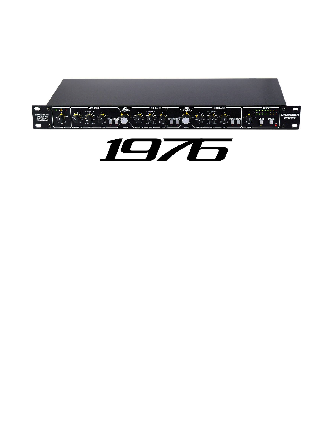
DRAWMER
1976 STEREO 3 BAND SATURATION AND WIDTH PROCESSOR
INTRODUCTION
The 1976 3 band stereo saturation and width processor has been designed to inject character, colour & life into your
recordings and live sound in a style endemic of the classic equipment of the 1970's. The completely analogue saturation
of the 1976 will provide the realism that plug-ins can only aspire to, replacing the harsh, sterile digital sound with
fullness, softness and warmth. Why emulate saturation when you can have the real thing?
Inspired by the highly acclaimed saturation and width features of our DC2476 Digital Mastering Processor the 3 bands
of independent saturation of the 1976 have been designed to add the pleasing imperfections that are so endemic in
classic gear. Saturation is ideal for adding fullness to your music, taking your music from a cold, bleak landscape to a
warm, bright vista. In addition, however, unlike conventional saturation products the 1976 also features 3 bands of stereo
width control to really bring out the depth and add real presence to your mix, and all with a single, yet comprehensive
set of controls that provide genuine stereo operation.
What is saturation? Saturation in music production is something that can really enrich the sound in your mix by
adding a subtle form of distortion that adds pleasant-sounding harmonics. It originates from the analog days when audio
recordings ran through various pieces of hardware, each one adding their own character to the music giving the audio a
pleasant quality that was much sought after. Today, in the digital age, these characteristics no longer occur naturally,
giving an overly clean, sterile quality to the audio, with saturation plug-ins used to emulate those not present. The 1976
allows you to add this character in a completely analogue, natural way. However, it's use is not only limited to digital
recordings, it'll add presence, warmth and life to any audio regardless of how it's recorded, whether its drum, vocals,
synths and more, in digital or analogue.
What about 3 Band Saturation? Because the 1976 as 3 bands of independent saturation it can pull off amazing feats
that single-band saturation could never accomplish. For example, it can bring out the bassline, adding presence and
grit without ruining the overall balance within the mix by adding distortion to the top end. Or enhance the vocals without
making the bottom sound muddy.
What about Width? Without stereo widening the mix won't jump out of the speaker and grab your listener, this is
where the 3 bands of the 1976 can be used to enhance the extra dimension to take the mix from a flat wall of sound to
a 3D immersive experience. It's likely your mix will have a stereo element already, however, the 1976 makes it super
easy to control these, widening and monogising where necessary to get the desired effect, and all just using the single
stereo controls of the low, mid and high bands. One major benefit of having independent width control for each of the
bands is to allow the high frequencies to be spread across a wider soundstage without affecting the low frequency end.
The key features are as follows:
Powerful 3 Band all Analogue Saturation for adding warmth to both your digital and analogue sounds.
Designed to Inject Character to your audio reminiscent of 1970's era gear and remove the sanitized
harshness that digital recordings suffer from.
3 band fully adjustable Stereo Width provides controllable depth and presence to you mix.
Fully Variable Crossover controls between the bands allows you to tune in to signals for different
amounts of independent saturation across the full frequency range.
Genuine stereo operation with one set of controls for both channels.
Can operate in Stereo and Mono.
The Mono switch helps highlight problems within the stereo mix.
Internal Low Hum Toroidal Linear Power Supply with Voltage Selector Switch.
Classic Drawmer Build Quality with Rugged Steel Chassis and Alluminium Front Panel.
Designed and manufactured by Drawmer in the UK.
DRAWMER 1976 OPERATOR’S MANUAL
3
Page 4
INSTALLATION
The 1976 is designed for standard 19" rack mounting and
occupies 1U of rack space. Avoid mounting the unit directly
above power amplifiers or power supplies that radiate
significant amounts of heat and always connect the mains
earth to the unit. Fibre or plastic washers may be used to
prevent the front panel becoming marked by the mounting
bolts. It is also advisable to leave space above the unit to
allow the heat to dissipate.
POWER CONNECTION
The 1976 unit will be supplied with a power cable suitable for domestic power outlets in your country. For your own safety,
it is important that you use this cable to connect to the mains supply earth. The cable must not be tampered with or
modified.
The power supply socket has an integral fuse drawer containing the power fuse of the same value, to suit the mains
voltage for which the unit has been supplied. Removal of the drawer is only possible with the power cord removed. The
fuse should never blow under normal operation. If the fuse is suspected of having blown, then a fault will have occurred
and this fault condition should be inspected by a qualified service engineer. When replacing the fuse, always comply with
the Safety Instructions.
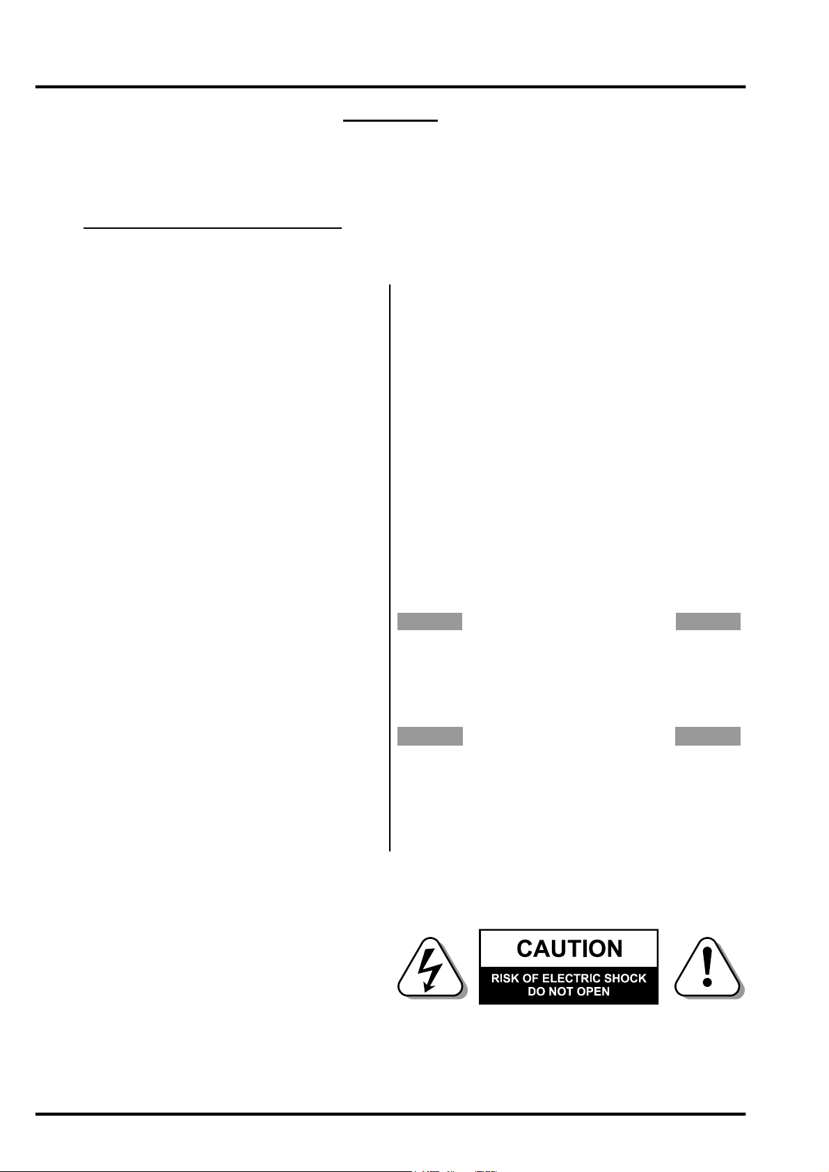
If the unit is to be used with a mains input operating voltage different to that for which the unit is supplied, the following
procedure must be carried out by a technically competent person, (see following diagrams)
1: Disconnect the unit from the mains.
2: Using a number 1 size pozidrive
screwdriver, remove the seven self
-tapping screws that retain the top cover. Tw
sc rews are f oun d al ong eac h
side; two along the top edge at the rear;
and the upper central screw on the front
facia panel.
3: Slide the voltage change-over switch
(S11) until the correct (or nearest) mains
input voltage is visible on the switch
actuator.
(see fig.2)
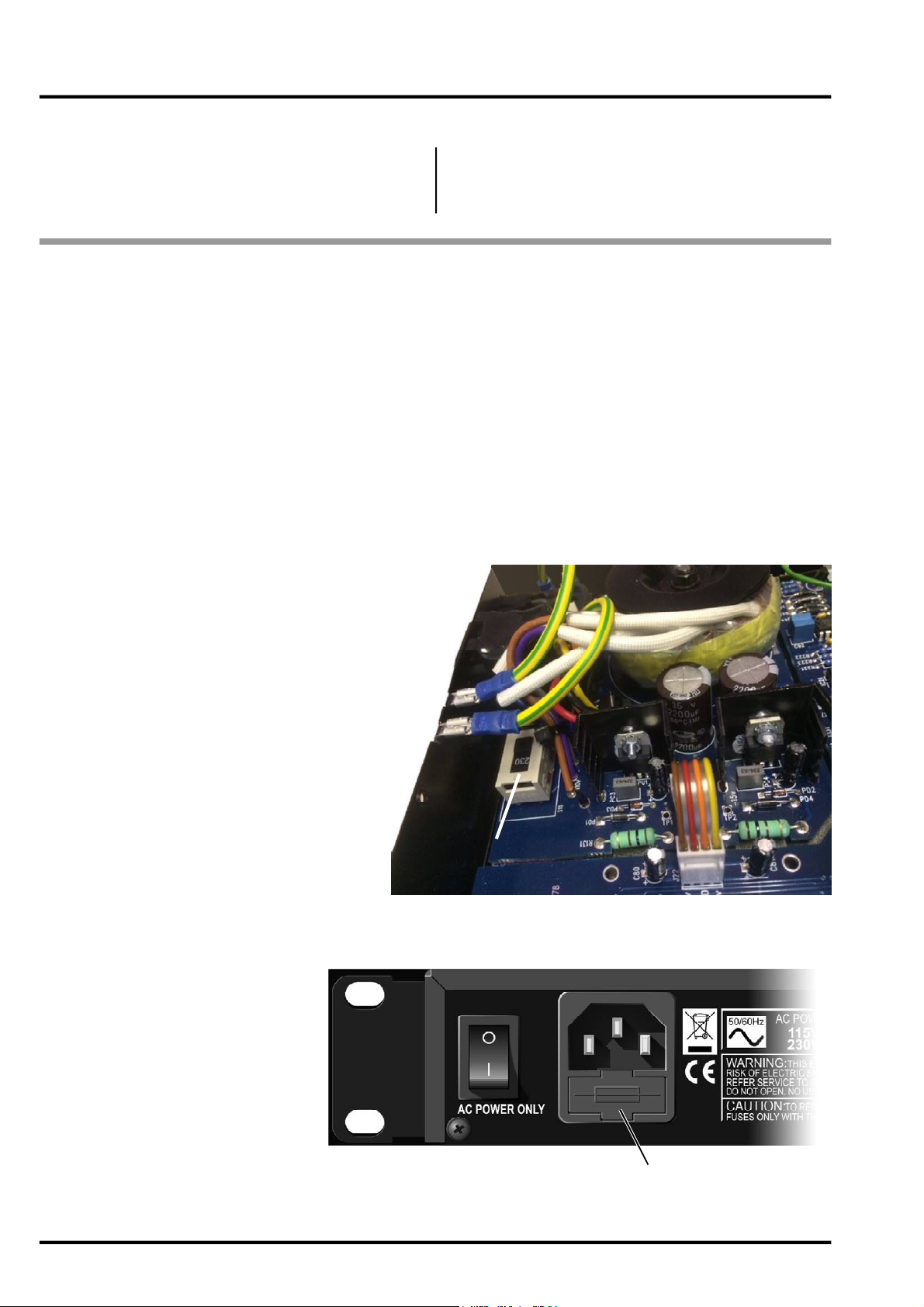
For co n ver sion to 115Vol t AC
(previously set to 230Volt AC).....
4a: Exchange the 160mA fuse below
the mains socket for a similar type rated
at 315mA
For co nversi o n to 230Vol t AC
(previously set to 115Volt AC).....
4b: Exchange the 315mA fuse below
the mains socket for a similar type rated
at 160mA
Voltage Selector
Switch located here
fig.2 The Voltage Selector Switch
In all cases:
5: Replace the top cover using the seven
screws.
6: Re-connect to mains power source.
4
Fuse
fig.3 The Location of the Fuse
DRAWMER 1976 OPERATOR’S MANUAL
Page 5

AUDIO CONNECTIONS
A typical setup for connecting the 1976 would be by the use of a Y-lead between the two input and output
xlr’s on the rear of the 1976 and insert point for the respective channel of the desk or interface for the digital
workstation - this would be repeated for both channels. The wiring of the Y-lead can be seen below.
The inputs and outputs are electronically balanced on conventionally wired XLRs (pin 1 screen, pin 2 hot,
pin 3 cold and XLR shell is connected to chassis). The operating level is nominally +4dBu. Balanced use is
recommended.
For connecting the 1976 to a mixing desk use the insert points as shown in the following diagram:
Alternatively, if you are using a digital workstation and have an audio interface that does not have insert
points, connect it to the analogue send (out) and return (in) of the relevant channels via four XLR to XLR/
jack cables. See your interface and software user manuals for the best procedure.
• Ground Loops:
If ground loop problems are encountered, never disconnect the mains earth, but instead, try disconnecting
the signal screen on one end of each of the cables connecting the outputs of the 1976 to the patchbay. If
such measures are necessary, balanced operation is recommended.
• Interference:
If the 1976 is to be used where it maybe exposed to high levels of disturbance such as found
close to a TV or radio transmitter, we advise that it is operated in a balanced configuration. The
screens of the signal cables should be connected to the chassis connection on the XLR connector
as opposed to connecting to pin1.
The 1976 conforms to the EMC standards.
DRAWMER 1976 OPERATOR’S MANUAL
5
Page 6

CHAPTER 2
CONTROL DESCRIPTION
The 1976 has been laid out to be as intuitive as possible. Essentially the layout of the 1976 comprises an input control
to the left of the unit, after this the stereo signal is split into identical low, mid and high bands of saturation and width,
each one processed separately at different frequencies without affecting the other, with the crossover frequency controls in betwee
. The audio is then summed back into a stereo signal again before output, located to the right of the unit (see
below diagram).
1 2 42
3 3 3
INPUT
1
(1a) INPUT LEVEL TRIM: OFF - +15dB
Typically, the Input Trim level control is used to match the output of the preceding
device to the input needs of the three saturation bands that the signal will pass
through.
(1b) METER:
The meter shows the effect of the input trim on the signal level to the saturation
bands.
The input control sets a balance between the incoming signal level and the amount (or drive) of saturation that
occurs. Set the input control so that the central yellow led is lit the majority of the time and the Red LED
only on the very highest signal peaks. This is the optimum balance between gain and saturation. If the input trim
is set too low (the green led) little saturation will occur. Alternatively, increasing the input trim control pushes more
level into the saturation circuitry and therefore more saturation occurs. However, set the input control too high (the
red led) and, as saturation is also a form of dynamic control, the overall gain level is attenuated as the audio
becomes more distorted.
2
X-OVER FREQUENCIES
The 6dB per octave crossover frequencies determine the
points within the frequency spectrum that one band stops
processing audio, and another band takes over.
(2a) LOW X-OVER FREQUENCY: 70Hz - 1.5kHz
Sets the frequency point at which the split between low
and mid bands occurs.
(2b) HIGH X-OVER FREQUENCY: 800Hz - 15kHz
Sets the frequency point at which the split between mid
and high bands occurs.
6
DRAWMER 1976 OPERATOR’S MANUAL
Page 7

LOW, MID & HIGH SATURATION & WIDTH
3
BANDS
The controls for the Low, Mid and High Bands are identical
and only differ in the frequency range that they operate
within, as set by the x-over frequencies (2).
(3a) SATURATE: 0 - 10
Sets the amount of drive that the saturation circuitry creates,
from none (0) through subtle and to extreme (10), adding
harmonic distortion within that band as it is rotated
clockwise, and warming the recording.
(3b) WIDTH: -5 (MONO) - +5 (WIDE)
In order to increase/decrease the stereo width and
spaciousness of each band the 1976 manipulates the left and right phases of the stereo signal so that one side is
in/out of phase with the other. Using the control the width of the stereo image of each band can be made narrower
(-5 mono) or wider (+5 wide) than the width that the incoming signal supplies. At the 0 position the width is not
affected (i.e. the Left and Right phase is unaltered) and is the same as that in the input.
You’ll notice that the nearer the mono end of the control the volume level of the band increases and when wider the
level decreases, and this must be taken into account when adjusting the Level control (3c) to maintain the band
balance within the recording.
(3c) LEVEL: OFF - +6
As the Saturation (3a) and Width (3b) controls have an affect on the volume of that particular band the Level control
is needed to offset these changes so that the overall level balance for low, mid and high within the recording is
maintained.
(3d) BYPASS: ON - OFF
In the OFF position all the controls of that particular band are in operation and saturation and width takes place. In
the ON position the signal for the low, mid, or high band is allowed to pass through to the summing stage without
being altered by the saturation stage (including width and gain).
(3e) MUTE: ON - OFF
In the ON position the signal for that particular band is effectively turned off (muted) and will not be heard at the
output.
Any combination of bypass and mute is available, for example, to hear only the signal of the low band mute the mid
and high bands etc. Using a combination of mute and bypass switches for the various bands allows the operator to
hear and monitor only the frequencies that are required and so ‘tune in’ to the low, mid and high frequency settings
using the x-over controls (2).
OUTPUT
4
The individual signals from the three bands are summed back
to a single stereo full band and pass through the output circuitry.
(4a) LEVEL TRIM: OFF - +12dB
The 1976 provides a single control to modify the stereo output
level after summing, without having to adjust the three band
gain controls (and thus altering the mix). Adjust so that the
output signal approaches the desired level only on signal peaks.
(4b) VU METER: -20 - +15dB
A 16 Led bar meter provides visual monitoring for the left and
right signals.
What is heard at the output is shown on this meter, so, with all
bands in operation the full band stereo signal is shown. However,
using a combination of the mute (3e) and bypass (3d) switches within the bands the meters can be made to show
any combination of signal.
(4c) MONO: ON - OFF
If you wish to record in mono treat the left and right channels as separate and use accordingly for both tracks. The
MONO switch in the output section is not used to monogise the signal for recording, as such, but has been
incorporated as a testing feature. Because the 1976 alters the phase between the left and right channels to control
the stereo width, activating the MONO switch (4c) will combine the stereo channels, the phase of the left and right
will cancel each other out leaving just the signal that lies in mono. This allows the engineer to hear what signal is
lost should it be played in mono and emphasize when you have ‘gone too far’ with the width controls (3b) of each
band. These can then be adjusted to preference.
(4d) BYPASS: ON - OFF
A fully balanced hard-wire unit bypass connects the input directly to the output. When active the VU Meter (4b) will
show the input levels.
(4e) POWER LED: Illuminted - OFF
The 1976 is on when the Led is illuminated, as controlled by the power switch on the reverse of the unit.
DRAWMER 1976 OPERATOR’S MANUAL
7
Page 8

QUICK SETUP PROCEDURE
Please note that the following procedure is only a guide. All audio is different, requiring numerous settings, however, this
should give a good staring point:
1) Set the front panel as shown in the diagram below: the Input vertical to 0dB, Set the controls to be the same
on all bands - Saturate fully counter-clockwise to 0, Width vertical at 0, and Level vertical at 0dB. Set the
Low X-Over to 70Hz and the High X-Over to 15kHz. Set the Output level vertical to 0dB. All switches
should be off.
2) Adjust on the Input knob so that the meter above reads the central, Yellow led for the majority of the signal. If
the green led is lit saturation will have a lesser effect on the signal and with red lit more saturation occurs but, in
addition, the level of each band is effected to a greater extent.
3) With the Low X-Over Frequency set fully counter-clockwise, and the High X-Over Frequency set fully clockwise,
listen to the audio and bring in the two knobs to the positions that you think the cross-over points should be set
- generally to separate the main bass and treble sounds from the mid-range. Using a combination of Mute and
Bypass switches for the various bands allows the operator to monitor only the frequencies that are required and so
tune the low, mid and high frequencies. (See ‘Useful Frequencies’ opposite)
4) Rotate the Saturate controls until the desired amount of saturation is hear for each band.
5) Because the saturation can have an affect on the gain, at this point it may be necessary to adjust the Level
control of each band to maintain a balance within your mix, emphasizing each band as you desire.
6) Whilst listening to the stereo mix adjust the Width control of each band until the desired stereo image is
achieved, rotating clockwise to widen the signal and anticlockwise to make it narrower.
7) Just like saturation Width can have an affect on the gain so at this point it may be necessary to adjust the Level
control of each band to maintain a balance within your mix.
8) Adjust the Output Level until the meter display reads the desired output level.
9) At this point the Output Bypass switch can be toggled to listen to the affect that the 1976 is having on the audio.
Adjust to suit.
10)As a final test of the audio, activated the Mono switch. This will outline what part of the signal is lost should it be
played in mono and emphasize when you have ‘gone too far’ with the width control. Adjust the width controls to
suit. Remember to deactivate the switch.
8
DRAWMER 1976 OPERATOR’S MANUAL
Page 9

Saturation and Width Tips
The following are a few handy tips to help get the most out of the 1976:
The Level Best
When setting up the 1976 it’s imperative that the input level has to be set up correctly as
it has a direct influence on the amount of saturation applied - the more you drive the input
the more saturation occurs. Set the input control so that the central yellow led is lit the
majority of the time and the red led only on the very highest signal peaks. Too low a level
(green led is lit on the meter) and little saturation will occur but the signal level will rise,
however, too high (the red led) and more saturation will take place but, as saturation is a
dynamic process, the signal will also be attenuated as the audio becomes distorted.
Use this - you can adjust the input level slightly rather than all three saturation controls to get the correct amount of
distortion desired. You will need to adjust the output level to compensate. Bare in mind that this should only be done
subtly once the three bands are close to correct in the first place.
Useful Frequencies
As the 1976 comprises a set of crossover filters that splits the audio signal into three frequency bands it is imperative that
these bands are set correctly. The following diagram provides a general idea of some useful frequencies that will aid in
setting the crossover frequencies:
Use your ears
There are no hard and fast rules of how to apply saturation. In theory saturation can be applied to any audio signal, after all, on
the whole it’s used to emulate old recording equipment where there was no option but to have analogue saturation in one form
or another. It really is a case of playing with the 1976 saturation controls until you like the sound and it enriches your mix. Be
careful not to over do it though because saturation is capable of completely ruining the audio.
As a rule apply the saturation until you can hear it then back it off to make it more subtle.
Where it sat
As mentioned, saturation can be used pretty much anywhere, however it can be applied to some sounds far more effectively
than others:
Percussion
Drums are one of the best sounds in which to use saturation. It can be used to 'glue' the whole drum bus together, injecting
some punch and excitement, giving them depth and life, and adding harmonics that are pleasing to the ear, whilst taming
rogue transients and high end harshness using natural compression.
DRAWMER 1976 OPERATOR’S MANUAL
9
Page 10

Basslines
If your bassline sounds a little flat and lifeless it will really benefit from a adding some saturation. This will bring out the grit,
dirty the sound and fatten it out. And we're not just talking about bass guitar here, use it on sine generated basslines to
make them sound more natural, and push them out into the mix.
Experiment here, and drive the saturation hard to see if the heavily distorted sound appeals.
Synths
Synths tend to sound too digital and clinical. Saturation will bring them to life, making them sound warmer, more natural,
and closer to the analogue sound that they emulate. It'll inject harmonics and grit, and make the synths stand out more in
the mix. With synths saturation should be used fairly subtly - add saturation until its noticeable and then back it off a little.
Vocals
Saturation is one of the secrets to great sounding vocals. Your vocal recordings may sound good but saturation will make
them sing (pun intended). It will make any vocal sound fuller, especially thin and dull voices, and will warm and tame harsh
sounding vocals by subtly softening sibilance. Don't go over the top though, keep the harmonic distortion gentle or it could
ruin the vocals all together.
Mix
For all of it's pros, digital recording has a major drawback, by it's very nature it sounds too, well, digital. It's too harsh, too
clean. Saturation can be the key here. It will add harmonic distortion to inject life and warmth into the mix, and help your
digital mixes sound more like those from the analogue recording era.
Just passing the audio through an analogue device will have some effect on warming the mix, though passing it through
the 1976 will take your mixes to the next level. Subtle saturation is the key here. Don't add too much distortion, it can quickly
ruin a mix if too harsh. Turn up the saturation controls until you can here it making a difference and then back it off a little.
Things Don’t Stack Up
Of course it’s perfectly correct to use saturation on multiple individual instruments and tracks throughout the mix but care
should be taken. The tracks sound fine by themselves but there is a risk of adding too much saturation to the mix if it’s stacked
and stacked on one track after another. Too much saturation will cause your mix to over distort, soften the transients and make
your mix sound mushy as well as attenuating the signal to some extent. W henever adding saturation to individual tracks
always test it as part of the entire mix also to limit this occurring.
Wide Open
As a general rule use the Mid and High frequencies to provide the space and depth to the mix and keep the Lows mono, using
the Width controls on the 1976 to taste.
It is essential that you check any widened stereo signal for mono compatibility, as the stereo image may drop significantly in
level, thin out, or even disappear alto gether when monogised into one, due to ph ase cancellation. It's good practice to
maintain some central image, especially in the mid tones. In addition, using pan controls it's easy to move the image around,
however, try to maintain the stereo image so that it sits right in front of you on the whole rather than off centre. It can be very
disconcerting for the listener.
Ensure that the low frequencies (i.e. anything below 100Hz) are mono, by setting the 1976 low frequency width control counterclockwise. This includes bass drums, bass guitar, percussion etc. This is essential if you're mixing for vinyl, as a stereo bass
will result in the needle skipping. Don't worry too much about how this will effect the stereo image as the ears are poor at
judging direction in low frequencies anyway - this is why Sub & LFE speakers can be placed almost anywhere.
You can use the Mono switch on the 1976 to see how the stereo signal has been affected.
Monogising
Check your mix in mono - often! Just because a mix sounds good in stereo doesn't mean it will sound good when the left and
right channels are combined. Why should you care if your mix sounds good in mono? W ell, most live music venues and dance
club sound systems are mono - running the PA or sound system in mono is common practice to ensure mu sic sounds good
everywhere in the room because it removes the ‘sweet spot’ and the complex phase issues of stereo. In many cases the low
frequencies will be put through a crossover and summed to mono before being sent to the sub, such as in a home theatre
system, for example. Monogising is also necessary when testing the audio for use on nonstandard applications such as for
broadcast or mobile phone.
Monogising will highlight phase problems. W hen a stereo mix is combined into mono any elements that are out of phase will
drop in level or may even disappear completely. This could be because the left and right outputs are wired out of phase but it’s
more likely to be due to phase cancellation caused by stereo widening effects and techniques, such as chorus.
Listening in mono also highlights problems with the stereo width and balance of the mix and is more apparent when you use
a lot of stereo-widening or width-enhancing techniques and tools. Switching mono in and out fairly q uickly may make it
apparent that the centre of the mix is shifting to the left or right, something that may go unnoticed if only working in stereo.
10
DRAWMER 1976 OPERATOR’S MANUAL
Page 11

GENERAL INFORMATION
CHAPTER 3
IF A FAULT DEVELOPS
For warranty service please call Drawmer Electronics Ltd. or
their nearest authorised service facility, giving full details of
the difficulty.
A list of all main dealers can b e f ou nd o n the Drawmer
web pages.
On receipt of this information, service or shipping instructions
will be forwarded to you.
No equipment should be returned under the warranty without
prior consent from Drawmer or their authorised representative.
For service claims under the warranty agreement a service
Returns Authorisation (RA) number will be issued.
Write this RA number in large letters in a prominent position
on the shipping box. Enclose your name, address, telephone
number, copy of the origin al sales invoice and a detailed
description of the problem.
Authorised returns should be prepaid and must be insured.
All Drawmer products are packaged in specially d esigned
containers for protection. If the unit is to be returned, the original
container must be used. If this container is not available, then
the equipment should be packaged in substantial shock-proof
material, capable of withstanding the handling for the transit.
CONTACTING DRAWMER
Draw mer Elec tronics L td ., will be p lease d to answer all
ap plication qu es ti ons to enh ance y our usage of thi s
equipmen t. Please ad dress co rrespondence to:
Drawmer (Technical Help line)
Coleman Street
Parkgate
Rotherham
S62 6EL
UK
Alternatively contact us by E-mail on :
tech@drawmer.com
Further information on all Drawmer dealers, Authorised service
departments and other contact information can be obtained
from our web pages on:
http://www.drawmer.com
1976 STEREO 3 BAND SATURATION AND WIDTH PROCESSOR
DATA SPECIFICATION
INPUT
Input Impedance 20k Ohms or greater
Maximum Input Level +18dBu
OUTPUT
Output Impedance <100 Ohms
Maximum Output Level +21dBu into 10k Ohms Load
FREQUENCY RESPONSE
20Hz to 20kHz +/-0.2dB
% DISTORTION (THD & NOISE) @ 1kHz
0dB (ref +4) 0.006%
POWER REQUIREMENTS
230Volt or 115V at 50-60hZ, 15VA
FUSE RATING
T160mA for 230Volt,
T315mA for 115Volt
Conforming to IEC 127-2
FUSE TYPE
20mm x 5mm, Class 3 Timed-Blo, 250Volt working
CASE SIZE
482mm (W) x 44mm (H) x 202mm (D)
WEIGHT 2.6 Kgs
DRAWMER 1976 OPERATOR’S MANUAL
11
Page 12

BLOCK DIAGRAM
12
1976 ver 01 B 30/05/19
DRAWMER 1976 OPERATOR’S MANUAL
Page 13

DRAWMER 1976 OPERATOR’S MANUAL
13
 Loading...